Cisco PEACOC Installation, Operation, and Maintenance Manual October 2023 Ordering Guide
Available Languages
Bias-Free Language
The documentation set for this product strives to use bias-free language. For the purposes of this documentation set, bias-free is defined as language that does not imply discrimination based on age, disability, gender, racial identity, ethnic identity, sexual orientation, socioeconomic status, and intersectionality. Exceptions may be present in the documentation due to language that is hardcoded in the user interfaces of the product software, language used based on RFP documentation, or language that is used by a referenced third-party product. Learn more about how Cisco is using Inclusive Language.
This document describes the Installation, Operation and Maintenance Manual procedures associated with the Cisco Patch Panel. The purpose of the document is to ensure the safe and correct installation of the Cisco Patch Panel shelf, as well as the safe and accurate management of the optical connection. Operations included this manual describe the procedures that should be followed when mounting the Cisco Patch Panel chassis onto the rack, when installing jumper cables for the first time, and also describe the procedures that should be followed when cleaning or replacing connectors.
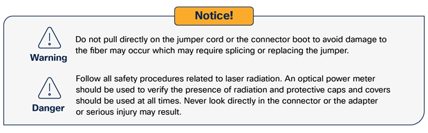
Throughout this document, important safety admonishments are used to alert the operator of possible hazards to persons or equipment. This safety information is conveyed through the use of Dangers, Warnings, and Cautions – it is important for these to be followed at all times. The various warnings are defined below and are highlighted throughout this document with use of the triangular alert icon (see below). The warnings shown below are listed in order of decreasing severity, either of personal injury or potential damage to equipment.
Danger: Danger is used to indicate a possible hazard which will cause severe personal injury, death, or substantial property damage if the hazard is ignored.
Warning: Warning is used to indicate a possible hazard which can cause severe personal injury, death, or substantial property damage if the hazard is ignored.
Caution: Caution is used to indicate a possible hazard which will or may cause minor personal injury, or property damage if the hazard is ignored.
Danger: Infrared radiation is invisible and can seriously damage the retina of the eye. Do not look into the ends of any optical fiber or connector. Do not look directly into the optical adapters when a connector is removed during cleaning or when they are being replaced. The use of an optical power meter should be used to verify active fibers. A protective cap or cover MUST be immediately placed over any live adapter or optical fiber connector to avoid the potential of dangerous amounts of radiation exposure. This practice will also help to prevent dirt particles from entering the optical pathway which may affect transmission performance.
Caution: When working with the Cisco Patch Panel shelf at a height that is above easy reach, an A-frame type of step ladder should be used to provide a safe and secure footing.
3.1. General principles for the Cisco Patch Panel Operation
The Cisco Fiber Patch Panel is an ultra-high density optical fiber patch panel used to safely and accurately manage small form factor optical fiber connectors in a high density configuration. The Cisco Patch Panel shelf is suitable for use in a central office, data center, CATV head end, CEV, customer premise, or other indoor environment, all while not requiring any special engineering, installation, or handling procedure.
The Cisco Patch Panel shelf is a 1RU high patch panel which is shipped with 144 pre-installed LC optical adapters on its front. To further reduce installation time for the customer, the Cisco Patch Panel shelf is ordered with 3x8 MPO connectors on the backplane of the patch panel. The Cisco Patch Panel optical fiber shelf is compatible with standard 19-inch frames or relay racks, and it will integrate with existing vertical and horizontal cable management trays. It is designed to be used with 1.2mm simplex LC jumper cables which occupy only ½ the space of a typical 1.6mm jumper and only 1/3 the space of a conventional 2.0mm jumper. This results in substantial savings in both weight and space in both horizontal and vertical cable trays.
Combined with the incredibly high port density, the Cisco Fiber Patch Panel is an excellent choice whenever aggressive subscriber growth is anticipated or for existing environments which have limited available space for continued growth.
The Cisco Patch Panel has been tested by Telcordia for NEBS Level 3 compliance with GR-449-CORE, Issue 3.
3.1.1.1. Mechanical
| Number of Connections |
144 |
| Accessibility |
Front and rear access on each cassette |
| Dimensions |
8.4”L x 19”W x 1.7”H (1RU) – Short Chassis |
| Width |
19” Rack Standard |
| Total Weight |
3.2 kgs (7.0 lbs) maximum |
| Cable Type |
Cisco Patch Panel cable (default): standard 1.2mm / 900um |
| Fiber Type |
G657B3 (Recommended) |
| Connector Type (Front) |
LC/UPC Duplex (default); other types available on request |
| Cable Sleeve |
200mm (Single or Dual) |
| Mounting Options |
Repositionable mounting brackets |
3.1.1.2. Environmental
| Parameter |
Specification |
Remarks |
| Operating Conditions |
-40C to +75C (-40oF to 167oF) |
Up to 85% humidity |
| Storage Conditions |
-40C to +75C (-40oF to 167oF) |
Up to 93% humidity |
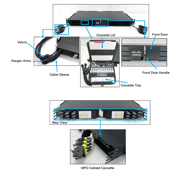
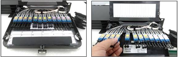
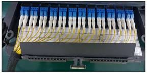
The following key parts of the Cisco fiber patch panel shelf are referenced throughout this document. Please refer back to the images below as needed to ensure that the proper procedures are strictly followed.
Warning: Failure to follow the procedures in this manual can result in damage to optical fiber cable or the optical connectors. This may further result in a loss of service for active subscribers.
4. Installation of the Cisco Patch Panel
For bonding and grounding, please follow approved company procedures.
Cisco Patch Panel should be installed in a grounded frame per approved company grounding procedures. Proper electrical bonding between the Cisco Patch Panel and the frame is achieved with the appropriate screws. Additional bonding can be achieved with the placement of a Star Washer between the frame and the Cisco Patch Panel mounting bracket when it is being screwed into the frame.
Parts of the Cisco Patch Panel
Please read and follow this manual as your operating guide. To ensure the integrity of the signal and safety of active fibers, please stop immediately and check the associated conditions if you encounter any strong resistance during operation of any of the moving parts. The Cisco Patch Panel shelf is ordered with either pre-terminated cables/pigtails or with no cables.
4.1.1. Unpack each container while carefully checking the contents for damage and verify with the packing slip. If damage is found or parts are missing, file a claim with the commercial carrier and notify Cisco Customer Service. Save the damaged cartons for inspection by the carrier.
4.1.2. Save all shipping containers for use if the equipment requires shipment at a future date.
First locate the equipment rack and mounting location designated for the Cisco Patch Panel chassis.

4.2. Installation of the Cisco Patch Panel Shelf without Pre-Installed Cables
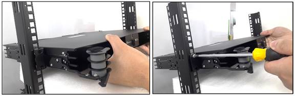
4.2.1 Hold either the empty or pre-loaded Cisco Patch Panel shelf in place and align the bracket holes with the holes on the equipment rack. Using compatible rack screws (not provided), mount the unit onto the rack, and then tighten the screws
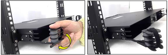
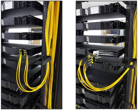
4.2.2. To straighten the cable hanger, move the head of the cable hanger by swinging it outwards the chassis until it locks into place.
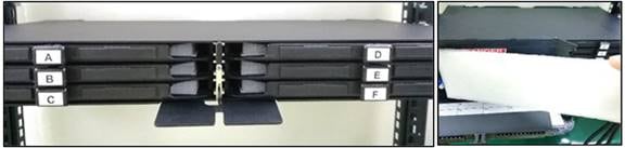
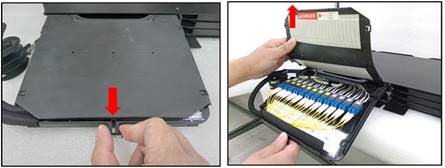
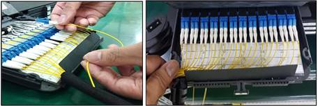
4.2.3. Open the front door of the chassis by turning the front door handle clockwise or counter clockwise to the open position, partially withdraw each cassette installed, open the front portion of each unit and remove and discard the protective foam.
4.2.4. Close each cassette lid, push each cassette back in and close the front door.
4.3. Rear entry of feeder/Input MPO cables
Once the Cisco Patch Panel shelf with no pre-terminated cables/pigtails is installed, the feeder/input cables will be installed at a later time. These cables will enter the Cisco Patch Panel shelf through the rear, and will terminate on the rear side of the LC adapters in the front.
4.3.1. Attaching MPO cables to chassis equipped with pre-terminated MPO cassettes
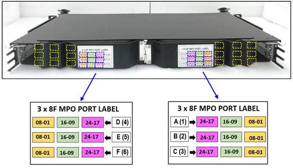
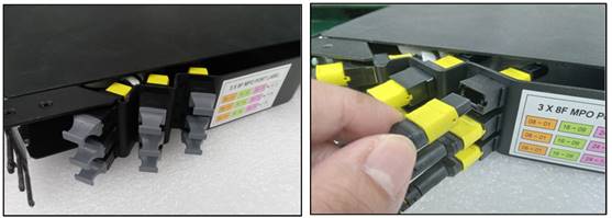
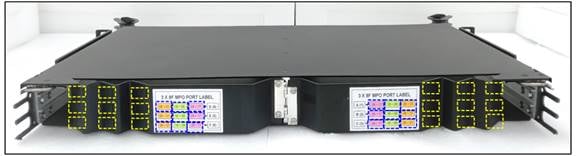
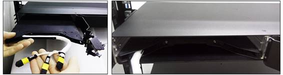
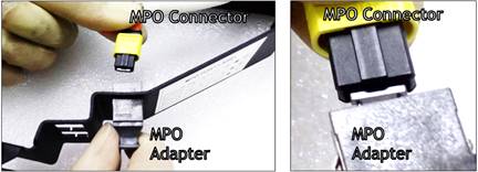
4.3.1.1 Plug in the MPO connectors on the cable into the MPO adapters on the chassis. Each cassette has three MPO slots on the rear door. (Reminder: Inspect, clean, Inspect, connect both sides of the connector (ICIC)). Since there are 8F MPOs, plug in all three MPOs in their corresponding locations as marked on the panel. MPO 1 will be for ports 1 to 8, MPO 2 will be for ports 9 to 16, and MPO 3 will be for ports 17 to 24. Refer to the colored MPO label guides attached on the rear doors.
4.3.1.2. For MPO jumper cable connections on the rear door, please provide at least ten inches (10”) cable slack as provision for rear door opening clearance.
4.3.1.3. Route and connect the MPO cable to its terminating end.
Installation complete
4.3.2. Installing an MPO cassette to an empty slot in the panel
4.3.2.1. Move to the rear of the chassis. Identify the MPO knockouts in the rear door.
4.3.2.2. Open the rear door and remove all 3 knockouts associated with each cassette to be installed in the chassis. The number of knockouts should match the number of MPOs to be installed.
4.3.2.3. Install MPO adapters in each knockout of chassis. Ensure the correct orientation of the adapter is maintained.
4.3.2.4. While the chassis back door is open, insert cassettes from the rear to the desired tray location. Insert the front cable sleeve (black) inside the chassis and position the cassette on the bottom layer of the chassis. Finally, push the cassette forward into position.
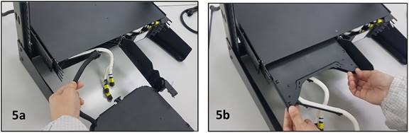
4.3.2.5. Get another cassette and insert the front cable sleeves (black) into the chassis (5a). position and push to insert the cassettes on the middle slot of the chassis (5b).
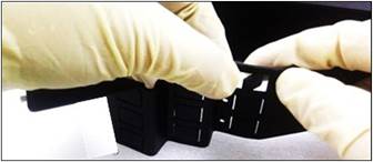
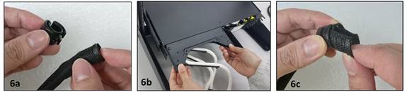
4.3.2.6. For the top slot cassette, remove the black plastic ring clip from the front cable sleeve (6a). Insert the black cable sleeve through the front of the chassis, then insert the cassette from the rear pushing the cable sleeve forward (6b). Reattach the black plastic ring clip to the sleeve (6c).
4.3.2.7. Repeat steps 4.3.2.4 through 4.3.2.6 for the cassettes on the other side of the chassis.
4.3.2.8. After the cassette is inserted into the Chassis, remove dust caps from both the MPO connector(s) and MPO adapter.
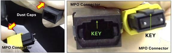
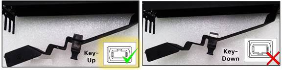
4.3.2.9. Insert MPO Connector(s) from the cassette into the MPO adapters on the back door. Push MPO connector in until a “click” sound is heard upon attachment. Ensure the right orientation of MPO Connector and MPO Adapter (e.g. KEY-UP)
4.3.2.10. Once all connectors are connected, close the back door.
Installation complete
5. Operation of the Cisco Patch Panel
Once the Cisco Patch Panel shelf has been installed all further connections/patching is done through the front of the chassis through various cassettes and connector types.
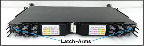
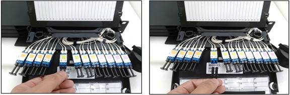
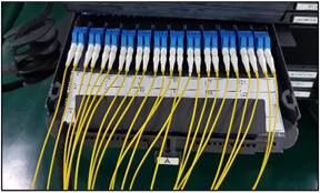
Viewing from the front of the Cisco Patch Panel, cassette trays are labeled A, B, and C from top to bottom on the left side. Trays on the right side are labeled D, E, and F from top to bottom. (See image below).
5.1. Accessing the adapters from the front and installing/patching jumpers on the front plane of the adapters.
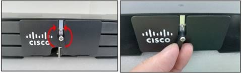
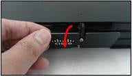
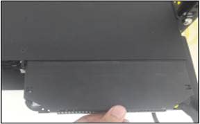
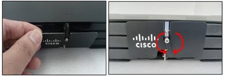
5.1.1. Rotate the door handle; it can be turned clockwise or counterclockwise; 180°.
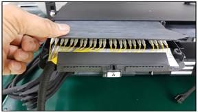
5.1.2. Drop the front door down. When the door is open, identify the cassette that you will work on.
5.1.3. Hold the cassette handle and pull the cassette until after the bottom hinge is out.
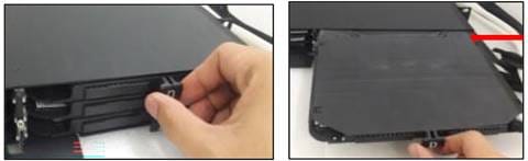
5.1.4. Press down on the front tab, then lift up the lid, loosen all the cassette snaps, and then the adapters will be exposed.
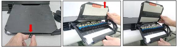
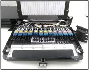
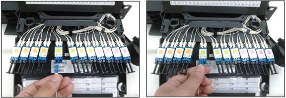
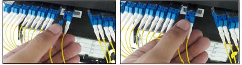
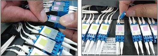
5.1.5. Identify the port based on the laser mark in the spreadable arms and the cable marker on each cable.
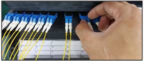
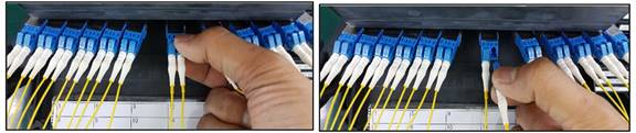
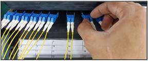
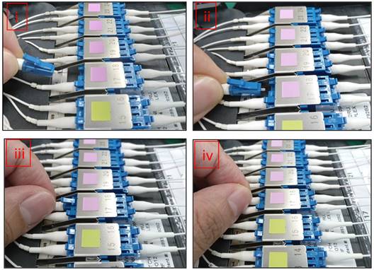
5.1.6. Isolate the port to be worked on by gently moving away all of the connectors to the left and right side of the desired connector. (spreadable function).
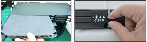
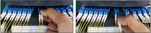
5.1.7. Remove the dust caps to insert the connectors to the LC/UPC simplex adapters. Carefully hold the cassette adapter holder then simply pull out the dust cap.
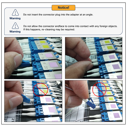
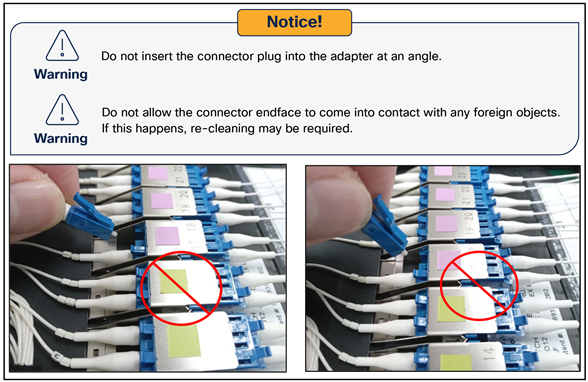
5.1.8. To insert the connector into the adapter, simply push horizontally on the housing of the connector until it is fully seated in the adapter. An audible click will be heard when it is properly inserted. (Reminder: Inspect, clean, Inspect, connect both sides of the connector (ICIC)).
5.1.9. Repeat steps 5.1.5 through 5.1.8 for any additional connectors that need to be inserted into the front side of the adapters.
5.2. Organizing and securing the cassette tray
Once all of the jumper cables are properly connected on the front plane of the tray, the cables must be properly organized and secured in the tray before the tray may be closed.
5.2.1. Organizing the Front Cables
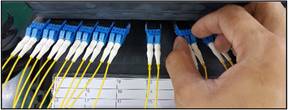
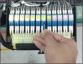
5.2.1.1. Realign the 24 front connectors after the insertion of cables by gently pushing in from both the left and right side.
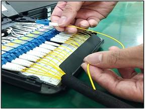
5.2.1.2. Gather all of the loose jumpers with your hands in line with the connectors. Gradually shift the collection point for the bundle and place beneath the cable protection flap towards the black cable sleeve.
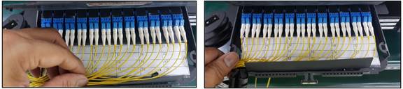
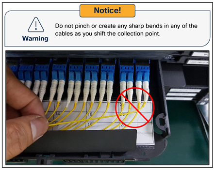
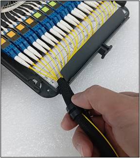
5.2.1.3. Guide the cable bundle towards the black plastic ring clip from the front cable sleeve. Be sure the bundle is beneath the cable protection sleeve so as not to pinch any of the cables when doing so. Insert the cables into the split sleeve.
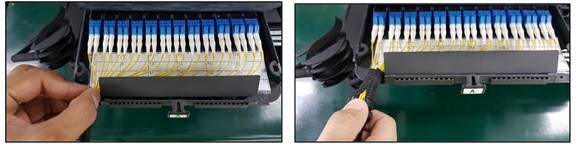
5.2.1.4. Pull the black plastic ring clip from the front cable sleeve to easily complete the cable insertion.
5.2.1.5. Make sure that the front cables are properly managed.
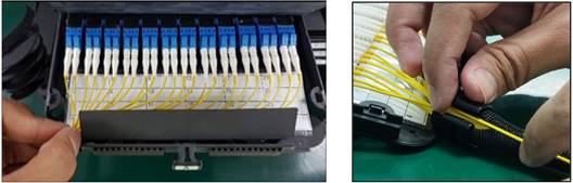
5.2.1.6. Close the lid and secure the snaps. Avoid pinching the cables.
5.2.1.7. Once the cassette lid is closed, gently push the cassette inside the chassis.
5.2.1.8. Close the front door and turn the front door handle; 180°.
5.2.1.9. Put back the cable sleeve to the cable hanger arm
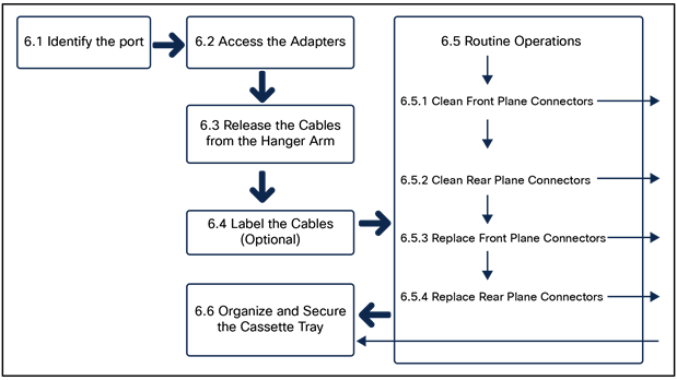
6. Maintenance of the Cisco Patch Panel
6.3 Releasing the cables from the hanger arm
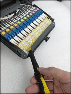
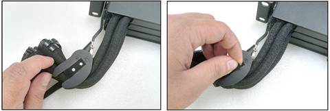
6.3.1. Unwrap the cable sleeves from the cable hanger arm.
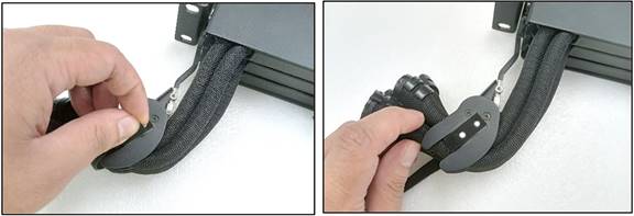
6.3.2. Slide out the cassette, press down on the front tab, and lift up the flap to expose the jumper cables.
6.3.3. Separate a jumper by gently pulling it out of the black cable sleeve. When needed, remove other cables or the rest of the bundle from the cable sleeve as well.

6.3.4. Allow the front cables to fall freely.
6.4 Labelling the cables (optional)
6.4.1. Put labelling on the front jumper cables.
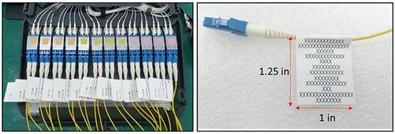
For labelling of front cables patched to the cassette, a flag label can be used. This label should be attached at the end of the boot. Kindly refer to the following suggestions for labelling sizes:
| Parameter |
Recommendation |
| Label Length (unfolded) |
2.5 inches |
| Label Length (folded) |
1.25 inches |
| Label Width |
1 inch |
| Font Type |
Arial Narrow |
| Font Size |
8 |
| Maximum No. of Rows |
12 |
| Characters per Row |
Approximately 12-17 Characters |
Please be advised that other labelling options such as the use of barrel labels may not be suitable for use in the Cisco Patch Panel.
6.5.1. Cleaning the front plane connector
6.5.1.1 Identify the tray and port using the procedure in Section 5.1.
6.5.1.2 Isolate the port to be worked on by gently moving away all of the connectors to the left and right side of the desired connector.
6.5.1.3. While gently depressing the connector latching tab, pull on the connector housing to un-mate the connector plug from the adapter.

6.5.1.4. Perform connector end face and/or adapter cleaning using your approved company procedures.
6.5.1.5. To reinsert the connector into the adapter, simply push horizontally on the connector housing until it is fully seated in the adapter. An audible click will be heard when it is properly inserted. (Reminder: Inspect, clean, Inspect, connect both sides of the connector (ICIC)).
6.5.2. Cleaning the rear plane connector
6.5.2.1. Identify the tray and port using the procedure in Section 5.1.
6.5.2.2. Isolate the port to be worked on by gently moving away all of the connectors to the left and right side of the desired connector.
6.5.2.3. Lift the flap which covers the rear plane of the connector shelf; using one hand to support the bottom of the adapter, gently depress the connector latching tab to unlock and remove the connector from the adapter.
6.5.2.4. Perform connector end face and/or adapter cleaning using your approved company procedures.
6.5.2.5. To insert the connector for the jumper cable into the adapter, (i) insert the boot end of the connector first by angling it under the other cables, (ii) align the connector with the adapter, and (iii) push horizontally in the connector housing until it is fully seated in the adapter. (iv) An audible click will be heard when it is properly seated. (Reminder: Inspect, clean, Inspect, connect both sides of the connector (ICIC)).
6.5.3. Replacing a front panel jumper
6.5.3.1. Identify the tray and port using the procedure in Section 5.1.
6.5.3.2. Isolate the port to be worked on by gently moving away all of the connectors to the left and right side of the desired connector.
6.5.3.3. While gently depressing the connector latching tab, pull on the connector housing to un-mate the connector plug from the adapter.
6.5.3.4. Install a protective cap on the connector plug and a dust cover on the adapter.
6.5.3.5. Carefully separate the jumper from the remaining bundle of cables. Remove the jumper by pulling it out of the black cable sleeve and trace it all the way back to the interface with the storage tray or trough on the side of the rack (if used). Follow your company procedures for removing cable from the remainder of the cable management system.
6.5.3.6. To insert the replacement jumper, push horizontally on the connector housing until it is fully seated in the adapter. An audible click will be heard when it is properly inserted.
6.5.3.7. Route the cable underneath the cable protection flap to join it with the bundle. Make sure to not pinch any of the cables when doing so. Guide the cable towards the black plastic ring clip from the front cable sleeve. Insert the cable into the split sleeve.
6.5.3.8. Pull the black plastic ring clip from the front cable sleeve to easily complete the cable insertion.