Comprehensive Guide to Configuring and Troubleshooting Frame Relay
Available Languages
Contents
Introduction
Frame Relay is an industry-standard, switched data link layer protocol that handles multiple virtual circuits using High-Level Data Link Control (HDLC) encapsulation between connected devices. In many cases, Frame Relay is more efficient than X.25, the protocol for which it is generally considered a replacement. The following figure illustrates a Frame Relay frame (ANSI T1.618).
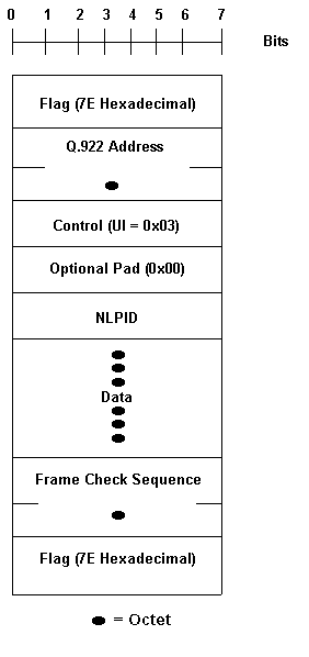
Note in the above figure, Q.922 addresses, as presently defined, are two octets and contain a 10-bit data-link connection identifier (DLCI). In some networks Q.922 addresses may optionally be increased to three or four octets.
The "flag" fields delimit the beginning and end of the frame. Following the leading "flag" field are two bytes of address information. Ten bits of these two bytes make up the actual circuit ID (called the DLCI, for data-link connection identifier).
The 10-bit DLCI value is the heart of the Frame Relay header. It identifies the logical connection that is multiplexed into the physical channel. In the basic (that is, not extended by the Local Management Interface [LMI]) mode of addressing, DLCIs have local significance; that is, the end devices at two different ends of a connection may use a different DLCI to refer to that same connection.
Before You Begin
Conventions
Refer to Cisco Technical Tips Conventions for more information on document conventions.
Prerequisites
For more information and definitions for the terms used in this document, please refer to the Frame Relay Glossary.
Components Used
This document is not restricted to specific software and hardware versions.
The information presented in this document was created from devices in a specific lab environment. All of the devices used in this document started with a cleared (default) configuration. If you are working in a live network, ensure that you understand the potential impact of any command before using it.
Background Theory
Frame Relay was originally conceived as a protocol for use over ISDN interfaces. Initial proposals to this effect were submitted to the International Telecommunication Union Telecommunication Standardization Sector (ITU-T) (formerly the Consultative Committee for International Telegraph and Telephone [CCITT]) in 1984. Work on Frame Relay was also undertaken in the ANSI-accredited T1S1 standards committee in the United States.
In 1990, Cisco Systems, StrataCom, Northern Telecom, and Digital Equipment Corporation formed a consortium to focus Frame Relay technology development and accelerate the introduction of inter operable Frame Relay products. They developed a specification conforming to the basic Frame Relay protocol being discussed in T1S1 and ITU-T, but extended it with features that provide additional capabilities for complex internetworking environments. These Frame Relay extensions are referred to collectively as the LMI. This is the "cisco" LMI in the router as opposed to the "ansi" or "q933a" LMI.
Frame Relay provides a packet-switching data communications capability that is used across the interface between user devices (such as routers, bridges, host machines) and network equipment (such as switching nodes). User devices are often referred to as data terminal equipment (DTE), while network equipment that interfaces to DTE is often referred to as data circuit-terminating equipment (DCE). The network providing the Frame Relay interface can be either a carrier-provided public network or a network of privately owned equipment serving a single enterprise.
Frame Relay differs significantly from X.25 in its functionality and format. In particular, Frame Relay is a more streamlined protocol, facilitating higher performance and greater efficiency.
As an interface between user and network equipment, Frame Relay provides a means for statistically multiplexing many logical data conversations (referred to as virtual circuits) over a single physical transmission link. This contrasts with systems that use only time-division-multiplexing (TDM) techniques for supporting multiple data streams. Frame Relay's statistical multiplexing provides more flexible and efficient use of available bandwidth. It can be used without TDM techniques or on top of channels provided by TDM systems.
Another important characteristic of Frame Relay is that it exploits the recent advances in wide-area network (WAN) transmission technology. Earlier WAN protocols, such as X.25, were developed when analog transmission systems and copper media were predominant. These links are much less reliable than the fiber media/digital transmission links available today. Over links such as these, link-layer protocols can forego time-consuming error correction algorithms, leaving these to be performed at higher protocol layers. Greater performance and efficiency is therefore possible without sacrificing data integrity. Frame Relay is designed with this approach in mind. It includes a cyclic redundancy check (CRC) algorithm for detecting corrupted bits (so the data can be discarded), but it does not include any protocol mechanisms for correcting bad data (for example, by retransmitting it at this level of protocol).
Another difference between Frame Relay and X.25 is the absence of explicit, per-virtual-circuit flow control in Frame Relay. Now that many upper-layer protocols are effectively executing their own flow control algorithms, the need for this functionality at the link layer has diminished. Frame Relay, therefore, does not include explicit flow control procedures that duplicate those in higher layers. Instead, very simple congestion notification mechanisms are provided to allow a network to inform a user device that the network resources are close to a congested state. This notification can alert higher-layer protocols that flow control may be needed.
Configuring Basic Frame Relay
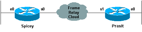
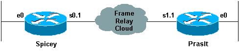
Once you have reliable connections to the local Frame Relay switch at both ends of the permanent virtual circuit (PVC), then it is time to start planning the Frame Relay configuration. In this first example, the Local Management Interface (LMI)-type defaults to "cisco" LMI on Spicey. An interface is by default a "multipoint" interface so, frame-relay inverse-arp is on (for point-to-point, there is no Inverse ARP). IP split horizon checking is disabled by default for Frame Relay encapsulation, so routing updates come in and out the same interface. The routers learn the data-link connection identifiers (DLCIs) they need to use from the Frame Relay switch via LMI updates. The routers then Inverse ARP for the remote IP address and create a mapping of local DLCIs and their associated remote IP addresses.
Network Diagram
Configurations
| Spicey |
|---|
Spicey#show running-config Building configuration... Current configuration : 1705 bytes ! version 12.1 service timestamps debug datetime msec service timestamps log datetime msec no service password-encryption ! hostname Spicey ! ! ! interface Ethernet0 ip address 124.124.124.1 255.255.255.0 ! interface Serial0 ip address 3.1.3.1 255.255.255.0 encapsulation frame-relay frame-relay interface-dlci 140 ! ! router rip network 3.0.0.0 network 124.0.0.0 ! line con 0 exec-timeout 0 0 transport input none line aux 0 line vty 0 4 login ! end |
| Prasit |
|---|
Prasit#show running-config Building configuration... Current configuration : 1499 bytes ! version 12.1 service timestamps debug datetime msec service timestamps log datetime msec no service password-encryption ! hostname Prasit ! ! ! interface Ethernet0 ip address 123.123.123.1 255.255.255.0 ! ! interface Serial1 ip address 3.1.3.2 255.255.255.0 encapsulation frame-relay frame-relay interface-dlci 150 ! ! router rip network 3.0.0.0 network 123.0.0.0 ! ! ! line con 0 exec-timeout 0 0 transport input none line aux 0 line vty 0 4 login ! end |
debug and show Commands
Before issuing debug commands, please see Important Information on Debug Commands.
-
show frame-relay map
-
show frame-relay pvc
-
show frame-relay lmi
-
ping <device name>
-
show ip route
Spicey
Spicey#show frame-relay map
Serial0 (up): ip 3.1.3.2 dlci 140(0x8C,0x20C0), dynamic,
              broadcast,, status defined, active

Spicey#show frame-relay pvc
PVC Statistics for interface Serial0 (Frame Relay DTE)
              Active     Inactive      Deleted       Static
  Local          1            0            0            0
  Switched       0            0            0            0
  Unused         0            0            0            0

DLCI = 140, DLCI USAGE = LOCAL, PVC STATUS = ACTIVE, INTERFACE = Serial0
  input pkts 83            output pkts 87           in bytes 8144
  out bytes 8408           dropped pkts 0           in FECN pkts0
  in BECN pkts 0           out FECN pkts 0          out BECN pkts0
  in DE pkts 0             out DE pkts 0
  out bcast pkts 41         out bcast bytes 3652
  pvc create time 01:31:50, last time pvc status changed 01:28:28
Spicey#show frame-relay lmi
LMI Statistics for interface Serial0 (Frame Relay DTE) LMI TYPE = CISCO
  Invalid Unnumbered info 0             Invalid Prot Disc 0
  Invalid dummy Call Ref 0              Invalid Msg Type 0
  Invalid Status Message 0              Invalid Lock Shift 0
  Invalid Information ID 0              Invalid Report IE Len 0
  Invalid Report Request 0              Invalid Keep IE Len 0
  Num Status Enq. Sent 550              Num Status msgs Rcvd 552
  Num Update Status Rcvd 0              Num Status Timeouts 0
Spicey#ping 123.123.123.1
Type escape sequence to abort.
Sending 5, 100-byte ICMP Echos to 123.123.123.1, timeout is 2 seconds:
!!!!!
Success rate is 100 percent (5/5), round-trip min/avg/max = 36/36/40 ms
Spicey#show ip route
Codes: C - connected, S - static, I - IGRP, R - RIP, M - mobile, B - BGP
       D - EIGRP, EX - EIGRP external, O - OSPF, IA - OSPF inter area
       N1 - OSPF NSSA external type 1, N2 - OSPF NSSA external type 2
       E1 - OSPF external type 1, E2 - OSPF external type 2, E - EGP
       i - IS-IS, L1 - IS-IS level-1, L2 - IS-IS level-2, ia - IS-IS
inter area
       * - candidate default, U - per-user static route, o - ODR
       P - periodic downloaded static route

Gateway of last resort is not set
     3.0.0.0/24 is subnetted, 1 subnets
C       3.1.3.0 is directly connected, Serial0
     124.0.0.0/24 is subnetted, 1 subnets
C       124.124.124.0 is directly connected, Ethernet0
R    123.0.0.0/8 [120/1] via 3.1.3.2, 00:00:08, Serial0
Prasit
Prasit#show frame-relay map
Serial1 (up): ip 3.1.3.1 dlci 150(0x96,0x2460), dynamic,
              broadcast,, status defined, active

Prasit#show frame-relay pvc
PVC Statistics for interface Serial1 (Frame Relay DTE)
              Active     Inactive      Deleted       Static
  Local          1            0            0            0
  Switched       0            0            0            0
  Unused         0            0            0            0
DLCI = 150, DLCI USAGE = LOCAL, PVC STATUS = ACTIVE, INTERFACE = Serial1
  input pkts 87            output pkts 83           in bytes 8408
  out bytes 8144           dropped pkts 0           in FECN pkts 0
  in BECN pkts 0           out FECN pkts 0          out BECN pkts 0
  in DE pkts 0             out DE pkts 0
  out bcast pkts 38         out bcast bytes 3464
  pvc create time 01:34:29, last time pvc status changed 01:28:05

Prasit#show frame-relay lmi
LMI Statistics for interface Serial1 (Frame Relay DTE) LMI TYPE = CISCO
  Invalid Unnumbered info 0             Invalid Prot Disc 0
  Invalid dummy Call Ref 0              Invalid Msg Type 0
  Invalid Status Message 0              Invalid Lock Shift 0
  Invalid Information ID 0              Invalid Report IE Len 0
  Invalid Report Request 0              Invalid Keep IE Len 0
  Num Status Enq. Sent 569              Num Status msgs Rcvd 570
  Num Update Status Rcvd 0              Num Status Timeouts 0

Prasit#ping 124.124.124.1
Type escape sequence to abort.
Sending 5, 100-byte ICMP Echos to 124.124.124.1, timeout is 2 seconds:
!!!!!
Success rate is 100 percent (5/5), round-trip min/avg/max = 36/36/36 ms
Prasit#show ip route
Codes: C - connected, S - static, I - IGRP, R - RIP, M - mobile, B - BGP
       D - EIGRP, EX - EIGRP external, O - OSPF, IA - OSPF inter area
       N1 - OSPF NSSA external type 1, N2 - OSPF NSSA external type 2
       E1 - OSPF external type 1, E2 - OSPF external type 2, E - EGP
       i - IS-IS, L1 - IS-IS level-1, L2 - IS-IS level-2, ia - IS-IS
inter area
       * - candidate default, U - per-user static route, o - ODR
       P - periodic downloaded static route
Gateway of last resort is not set
     3.0.0.0/24 is subnetted, 1 subnets
C       3.1.3.0 is directly connected, Serial1
R    124.0.0.0/8 [120/1] via 3.1.3.1, 00:00:19, Serial1
     123.0.0.0/24 is subnetted, 1 subnets
C       123.123.123.0 is directly connected, Ethernet0
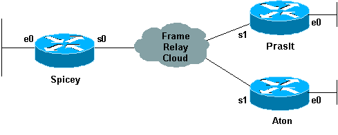
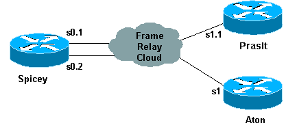
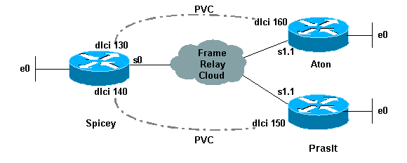
Configuring Hub and Spoke Frame Relay
In this example, the router learns which data-link connection identifiers (DLCIs) it uses from the Frame Relay switch and assigns them to the main interface. Then the router will Inverse ARP for the remote IP address.
Note: You will not be able to ping Prasit's serial IP address from Aton unless you explicitly add in Frame Relay maps on each end. If routing is configured correctly, traffic originating on the LANs should not have a problem. You will be able to ping if you use the Ethernet IP address as the source address in an extended ping.
When frame-relay inverse-arp is enabled, broadcast IP traffic will go out over the connection by default.
Network Diagram
Configurations
| Spicey |
|---|
spicey#show running-config Building configuration... ! version 12.1 service timestamps debug datetime msec service timestamps log datetime msec no service password-encryption ! hostname spicey ! ! ! ! interface Ethernet0 ip address 124.124.124.1 255.255.255.0 ! interface Serial0 ip address 3.1.3.1 255.255.255.0 encapsulation frame-relay frame-relay interface-dlci 130 frame-relay interface-dlci 140 ! ! router rip network 3.0.0.0 network 124.0.0.0 ! line con 0 exec-timeout 0 0 transport input none line aux 0 line vty 0 4 login ! end |
| Prasit |
|---|
prasit#show running-config Building configuration... Current configuration : 1499 bytes ! version 12.1 service timestamps debug datetime msec service timestamps log datetime msec no service password-encryption ! hostname prasit ! ! ! interface Ethernet0 ip address 123.123.123.1 255.255.255.0 ! interface Serial1 ip address 3.1.3.2 255.255.255.0 encapsulation frame-relay frame-relay interface-dlci 150 ! ! router rip network 3.0.0.0 network 123.0.0.0 ! ! line con 0 exec-timeout 0 0 transport input none line aux 0 line vty 0 4 login ! end |
| Aton |
|---|
aton#show running-config Building configuration... Current configuration: ! version 12.0 service timestamps debug uptime service timestamps log uptime no service password-encryption ! hostname aton ! ! interface Ethernet0 ip address 122.122.122.1 255.255.255.0 ! interface Serial1 ip address 3.1.3.3 255.255.255.0 encapsulation frame-relay frame-relay interface-dlci 160 ! router rip network 3.0.0.0 network 122.0.0.0 ! ! line con 0 exec-timeout 0 0 transport input none line aux 0 line vty 0 4 login ! end |
show Commands
-
show frame-relay map
-
show frame-relay pvc
-
ping <device name>
Spicey
spicey#show frame-relay map
Serial0 (up): ip 3.1.3.2 dlci 140(0x8C,0x20C0), dynamic,
              broadcast,, status defined, active
Serial0 (up): ip 3.1.3.3 dlci 130(0x82,0x2020), dynamic,
              broadcast,, status defined, active

spicey#show frame-relay pvc
PVC Statistics for interface Serial0 (Frame Relay DTE)
              Active     Inactive      Deleted       Static
  Local          2            0            0            0
  Switched       0            0            0            0
  Unused         0            0            0            0

DLCI = 130, DLCI USAGE = LOCAL, PVC STATUS = ACTIVE, INTERFACE = Serial0
  input pkts 32            output pkts 40           in bytes 3370
  out bytes 3928           dropped pkts 0           in FECN pkts 0
  in BECN pkts 0           out FECN pkts 0          out BECN pkts 0
  in DE pkts 0             out DE pkts 0
  out bcast pkts 30         out bcast bytes 2888
  pvc create time 00:15:46, last time pvc status changed 00:10:42

DLCI = 140, DLCI USAGE = LOCAL, PVC STATUS = ACTIVE, INTERFACE = Serial0

  input pkts 282           output pkts 291          in bytes 25070
  out bytes 27876          dropped pkts 0           in FECN pkts 0
  in BECN pkts 0           out FECN pkts 0          out BECN pkts 0
  in DE pkts 0             out DE pkts 0
  out bcast pkts 223        out bcast bytes 20884
  pvc create time 02:28:36, last time pvc status changed 02:25:14
spicey#
spicey#ping 3.1.3.2
Type escape sequence to abort.
Sending 5, 100-byte ICMP Echos to 3.1.3.2, timeout is 2 seconds:
!!!!!
Success rate is 100 percent (5/5), round-trip min/avg/max = 32/35/36 ms
spicey#ping 3.1.3.3
Type escape sequence to abort.
Sending 5, 100-byte ICMP Echos to 3.1.3.3, timeout is 2 seconds:
!!!!!
Success rate is 100 percent (5/5), round-trip min/avg/max = 32/35/36 ms
Prasit
prasit#show frame-relay map
Serial1 (up): ip 3.1.3.1 dlci 150(0x96,0x2460), dynamic,
              broadcast,, status defined, active

prasit#show frame-relay pvc

PVC Statistics for interface Serial1 (Frame Relay DTE)
              Active     Inactive      Deleted       Static
  Local          1            0            0            0
  Switched       0            0            0            0
  Unused         0            0            0            0

DLCI = 150, DLCI USAGE = LOCAL, PVC STATUS = ACTIVE, INTERFACE = Serial1
  input pkts 311           output pkts 233          in bytes 28562
  out bytes 22648          dropped pkts 0           in FECN pkts 0
  in BECN pkts 0           out FECN pkts 0          out BECN pkts 0
  in DE pkts 0             out DE pkts 0
  out bcast pkts 162        out bcast bytes 15748
  pvc create time 02:31:39, last time pvc status changed 02:25:14

prasit#ping 3.1.3.1
Type escape sequence to abort.
Sending 5, 100-byte ICMP Echos to 3.1.3.1, timeout is 2 seconds:
!!!!!
Success rate is 100 percent (5/5), round-trip min/avg/max = 36/36/36 ms
prasit#ping 3.1.3.3
Type escape sequence to abort.
Sending 5, 100-byte ICMP Echos to 3.1.3.3, timeout is 2 seconds:
.....
Success rate is 0 percent (0/5)
Aton
aton#show frame-relay map
Serial1 (up): ip 3.1.3.1 dlci 160(0xA0,0x2800), dynamic,
              broadcast,, status defined, active

aton#show frame-relay pvc

PVC Statistics for interface Serial1 (Frame Relay DTE)

              Active     Inactive      Deleted       Static
  Local          1            0            0            0
  Switched       0            0            0            0
  Unused         0            0            0            0

DLCI = 160, DLCI USAGE = LOCAL, PVC STATUS = ACTIVE, INTERFACE = Serial1

  input pkts 35            output pkts 32           in bytes 3758
  out bytes 3366           dropped pkts 0           in FECN pkts 0
  in BECN pkts 0           out FECN pkts 0          out BECN pkts 0
  in DE pkts 0             out DE pkts 0
  out bcast pkts 27         out bcast bytes 2846
  pvc create time 00:10:53, last time pvc status changed 00:10:53

aton#ping 3.1.3.1

Type escape sequence to abort.
Sending 5, 100-byte ICMP Echos to 3.1.3.1, timeout is 2 seconds:
!!!!!
Success rate is 100 percent (5/5), round-trip min/avg/max = 32/35/36 ms

aton#ping 3.1.3.2

Type escape sequence to abort.
Sending 5, 100-byte ICMP Echos to 3.1.3.2, timeout is 2 seconds:
.....
Success rate is 0 percent (0/5)
Connecting from Spoke to Spoke
You cannot ping from one spoke to another spoke in a hub and spoke configuration using multipoint interfaces because there is no mapping for the other spokes' IP addresses. Only the hub's address is learned via the Inverse Address Resolution Protocol (IARP). If you configure a static map using the frame-relay map command for the IP address of a remote spoke to use the local data link connection identifier (DLCI), you can ping the addresses of other spokes.
Configurations
| Prasit |
|---|
prasit#show running-config interface Ethernet0 ip address 123.123.123.1 255.255.255.0 ! interface Serial ip address 3.1.3.2 255.255.255.0 encapsulation frame-relay frame-relay map ip 3.1.3.3 150 frame-relay interface-dlci 150 |
show Commands
-
show frame-relay map
-
ping <device name>
-
show running-config
Prasit
prasit#show frame-relay map
 Serial1 (up): ip 3.1.3.1 dlci 150(0x96,0x2460), dynamic,
                    broadcast,, status defined, active
 Serial1 (up): ip 3.1.3.3 dlci 150(0x96,0x2460), static,
                    CISCO, status defined, active

 prasit#ping 3.1.3.3
 Type escape sequence to abort.
 Sending 5, 100-byte ICMP Echos to 3.1.3.3, timeout is 2 seconds:
 !!!!!
 Success rate is 100 percent (5/5), round-trip min/avg/max = 68/70/80 ms

 prasit#ping 122.122.122.1
 Type escape sequence to abort.
 Sending 5, 100-byte ICMP Echos to 122.122.122.1, timeout is 2 seconds:
 !!!!!
 Success rate is 100 percent (5/5), round-trip min/avg/max = 64/67/76 ms
Aton
aton#show running-config
 interface Ethernet0
 ip address 122.122.122.1 255.255.255.0
 !
 interface Serial1
   ip address 3.1.3.3 255.255.255.0
   no ip directed-broadcast
   encapsulation frame-relay
   frame-relay map ip 3.1.3.2 160
   frame-relay interface-dlci 160

 aton#show frame-relay map
 Serial1 (up): ip 3.1.3.1 dlci 160(0xA0,0x2800), dynamic,
                    broadcast,, status defined, active
 Serial1 (up): ip 3.1.3.2 dlci 160(0xA0,0x2800), static,
                    CISCO, status defined, active
 aton#ping 3.1.3.2

 Type escape sequence to abort
 Sending 5, 100-byte ICMP Echos to 3.1.3.2, timeout is 2 seconds:
 !!!!!
 Success rate is 100 percent (5/5), round-trip min/avg/max = 68/68/68 ms

aton#ping 123.123.123.1
Type escape sequence to abort.
Sending 5, 100-byte ICMP Echos to 123.123.123.1, timeout is 2 seconds:
!!!!!
Success rate is 100 percent (5/5), round-trip min/avg/max = 64/67/80 ms
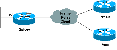
Configuring Frame Relay Subinterfaces
Frame Relay subinterfaces provide a mechanism for supporting partially meshed Frame Relay networks. Most protocols assume transitivity on a logical network; that is, if station A can talk to station B, and station B can talk to station C, then station A should be able to talk to station C directly. Transitivity is true on LANs, but not on Frame Relay networks unless A is directly connected to C.
Additionally, certain protocols, such as AppleTalk and transparent bridging, cannot be supported on partially meshed networks because they require "split horizon" in which a packet received on an interface cannot be transmitted out the same interface even if the packet is received and transmitted on different virtual circuits.
Configuring Frame Relay subinterfaces ensures that a single physical interface is treated as multiple virtual interfaces. This capability allows us to overcome split horizon rules. Packets received on one virtual interface can now be forwarded out another virtual interface, even if they are configured on the same physical interface.
Subinterfaces address the limitations of Frame Relay networks by providing a way to subdivide a partially meshed Frame Relay network into a number of smaller, fully meshed (or point-to-point) subnetworks. Each subnetwork is assigned its own network number and appears to the protocols as if it is reachable through a separate interface. (Note that point-to-point subinterfaces can be unnumbered for use with IP, reducing the addressing burden that might otherwise result).
Point-to-Point Subinterfaces
Network Diagram
Configurations
| Spicey |
|---|
Spicey#show running-config Building configuration... Current configuration : 1338 bytes ! version 12.1 service timestamps debug datetime msec service timestamps log datetime msec no service password-encryption ! hostname Spicey ! enable password ww ! ! ! ! interface Ethernet0 ip address 124.124.124.1 255.255.255.0 ! interface Serial0 no ip address encapsulation frame-relay ! interface Serial0.1 point-to-point ip address 3.1.3.1 255.255.255.0 frame-relay interface-dlci 140 ! ! router igrp 2 network 3.0.0.0 network 124.0.0.0 ! ! line con 0 exec-timeout 0 0 transport input none line aux 0 line vty 0 4 login ! end |
| Prasit |
|---|
Prasit#show running-config Building configuration... Current configuration : 1234 bytes ! version 12.1 service timestamps debug datetime msec service timestamps log datetime msec no service password-encryption ! hostname Prasit ! ! ! interface Ethernet0 ip address 123.123.123.1 255.255.255.0 ! interface Serial1 no ip address encapsulation frame-relay ! interface Serial1.1 point-to-point ip address 3.1.3.2 255.255.255.0 frame-relay interface-dlci 150 ! router igrp 2 network 3.0.0.0 network 123.0.0.0 ! line con 0 exec-timeout 0 0 transport input none line aux 0 line vty 0 4 login ! end |
show Commands
-
show frame-relay map
-
show frame-relay pvc
Spicey
Spicey#show frame-relay map
Serial0.1 (up): point-to-point dlci, dlci 140(0x8C,0x20C0), broadcast
             status defined, active

Spicey#show frame-relay pvc
PVC Statistics for interface Serial0 (Frame Relay DTE)

                 Active     Inactive      Deleted          Static
  Local          1               0            0               0
  Switched       0               0            0               0
  Unused         0               0            0               0

DLCI = 140, DLCI USAGE = LOCAL, PVC STATUS = ACTIVE, INTERFACE = Serial0.1

  input pkts 193              output pkts 175          in bytes 20450
  out bytes 16340             dropped pkts 0           in FECN pkts 0
  in BECN pkts 0              out FECN pkts 0          out BECN pkts 0
  in DE pkts 0                out DE pkts 0
  out bcast pkts 50         out    bcast bytes 3786
  pvc create time 01:11:27, last time pvc status changed 00:42:32

Spicey#ping 123.123.123.1
Type escape sequence to abort.
Sending 5, 100-byte ICMP Echos to 123.123.123.1, timeout is 2 seconds:
!!!!!
Success rate is 100 percent (5/5), round-trip min/avg/max = 36/36/36 ms
Prasit
Prasit#show frame-relay map
Serial1.1 (up): point-to-point dlci, dlci 150(0x96,0x2460), broadcast
             status defined, active

Prasit#show frame-relay pvc
PVC Statistics for interface Serial1 (Frame Relay DTE)

                Active     Inactive      Deleted          Static
 Local          1               0            0               0
 Switched       0               0            0               0
 Unused         0               0            0               0

DLCI = 150, DLCI USAGE = LOCAL, PVC STATUS = ACTIVE, INTERFACE =
Serial1.1

     input pkts 74               output pkts 89           in    bytes 7210
     out bytes 10963             dropped pkts 0           in    FECN pkts 0
     in BECN pkts 0              out FECN pkts 0          out BECN    pkts 0
     in DE pkts 0                out DE pkts 0
     out bcast pkts 24           out bcast bytes 4203
     pvc create time 00:12:25, last time pvc status changed 00:12:25

Prasit#ping 124.124.124.1
Type escape sequence to abort.
Sending 5, 100-byte ICMP Echos to 124.124.124.1, timeout is 2 seconds:
!!!!!
Success rate is 100 percent (5/5), round-trip min/avg/max = 36/36/36 ms
Hub and Spoke Subinterfaces
The following hub and spoke sample configuration shows two point-to-point subinterfaces and uses dynamic address resolution on one remote site. Each subinterface is provided with an individual protocol address and subnetmask, and the interface-dlci command associates the subinterface with a specified data-link connection identifier (DLCI). Addresses of remote destinations for each point-to-point subinterface are not resolved since they are point-to-point and traffic must be sent to the peer at the other end. The remote end (Aton) uses Inverse ARP for its mapping and the main hub responds accordingly with the IP address of the subinterface. This occurs because Frame Relay Inverse ARP is on by default for multipoint interfaces.
Network Diagram
Configurations
| Spicey |
|---|
Spicey#show running-config Building configuration... ! version 12.1 service timestamps debug datetime msec service timestamps log datetime msec no service password-encryption ! hostname Spicey ! ! ! ! interface Ethernet0 ip address 124.124.124.1 255.255.255.0 ! interface Serial0 no ip address encapsulation frame-relay ! interface Serial0.1 point-to-point ip address 4.0.1.1 255.255.255.0 frame-relay interface-dlci 140 ! interface Serial0.2 point-to-point ip address 3.1.3.1 255.255.255.0 frame-relay interface-dlci 130 ! router igrp 2 network 3.0.0.0 network 4.0.0.0 network 124.0.0.0 ! line con 0 exec-timeout 0 0 transport input none line aux 0 line vty 0 4 login ! end |
| Prasit |
|---|
Prasit#show running-config Building configuration... version 12.1 service timestamps debug datetime msec service timestamps log datetime msec no service password-encryption ! hostname Prasit ! interface Ethernet0 ip address 123.123.123.1 255.255.255.0 ! interface Serial1 no ip address encapsulation frame-relay ! interface Serial1.1 point-to-point ip address 4.0.1.2 255.255.255.0 frame-relay interface-dlci 150 ! router igrp 2 network 4.0.0.0 network 123.0.0.0 ! ! line con 0 exec-timeout 0 0 transport input none line aux 0 line vty 0 4 login ! end |
| Aton |
|---|
Aton#show running-config Building configuration... Current configuration: ! version 12.0 service timestamps debug uptime service timestamps log uptime ! hostname Aton ! ! ! interface Ethernet0 ip address 122.122.122.1 255.255.255.0 ! interface Serial1 ip address 3.1.3.3 255.255.255.0 encapsulation frame-relay frame-relay interface-dlci 160 ! router igrp 2 network 3.0.0.0 network 122.0.0.0 ! line con 0 exec-timeout 0 0 transport input none line aux 0 line vty 0 4 login ! end |
show Commands
-
show frame-relay map
-
show frame-relay pvc
Spicey
Spicey#show frame-relay map
Serial0.2 (up): point-to-point dlci, dlci 130(0x82,0x2020), broadcast
          status defined, active
Serial0.1 (up): point-to-point dlci, dlci 140(0x8C,0x20C0), broadcast
          status defined, active

Spicey#show frame-relay pvc
PVC Statistics for interface Serial0 (Frame Relay DTE)

              Active     Inactive      Deleted       Static
  Local          2            0            0            0
  Switched       0            0            0            0
  Unused         0            0            0            0

DLCI = 130, DLCI USAGE = LOCAL, PVC STATUS = ACTIVE, INTERFACE = Serial0.2

  input pkts 11            output pkts 22           in bytes 1080
  out bytes 5128           dropped pkts 0           in FECN pkts 0
  in BECN pkts 0           out FECN pkts 0          out BECN pkts 0
  in DE pkts 0             out DE pkts 0
  out bcast pkts 17         out bcast bytes 4608
  pvc create time 00:06:36, last time pvc status changed 00:06:36

DLCI = 140, DLCI USAGE = LOCAL, PVC STATUS = ACTIVE, INTERFACE = Serial0.1

  input pkts 33            output pkts 28           in bytes 3967
  out bytes 5445           dropped pkts 0           in FECN pkts 0
  in BECN pkts 0           out FECN pkts 0          out BECN pkts 0
  in DE pkts 0             out DE pkts 0
  out bcast pkts 17        out bcast bytes 4608
  pvc create time 00:06:38, last time pvc status changed 00:06:38

Spicey#ping 122.122.122.1
Type escape sequence to abort.
Sending 5, 100-byte ICMP Echos to 122.122.122.1, timeout is 2 seconds:
!!!!!
Success rate is 100 percent (5/5), round-trip min/avg/max = 32/35/36 ms

Spicey#ping 123.123.123.1
Type escape sequence to abort.
Sending 5, 100-byte ICMP Echos to 123.123.123.1, timeout is 2 seconds:
!!!!!
Success rate is 100 percent (5/5), round-trip min/avg/max = 36/36/36 ms
Prasit
Prasit#show frame-relay map
Serial1.1 (up): point-to-point dlci, dlci 150(0x96,0x2460), broadcast
          status defined, active

Prasit#show frame-relay pvc
PVC Statistics for interface Serial1 (Frame Relay DTE)

              Active     Inactive      Deleted       Static
  Local          1            0            0            0
  Switched       0            0            0            0
  Unused         0            0            0            0

DLCI = 150, DLCI USAGE = LOCAL, PVC STATUS = ACTIVE, INTERFACE =
Serial1.1

  input pkts 45            output pkts 48           in bytes 8632
  out bytes 6661           dropped pkts 0           in FECN pkts 0
  in BECN pkts 0           out FECN pkts 0          out BECN pkts 0
  in DE pkts 0             out DE pkts 0
  out bcast pkts 31         out bcast bytes 5573
  pvc create time 00:12:16, last time pvc status changed 00:06:23

Prasit#ping 124.124.124.1
Type escape sequence to abort.
Sending 5, 100-byte ICMP Echos to 124.124.124.1, timeout is 2 seconds:
!!!!!
Success rate is 100 percent (5/5), round-trip min/avg/max = 36/36/36 ms
Aton
Aton#show frame-relay map
Serial1 (up): ip 3.1.3.1 dlci 160(0xA0,0x2800), dynamic,
              broadcast,, status defined, active

Aton#show frame-relay pvc
PVC Statistics for interface Serial1 (Frame Relay DTE)

              Active     Inactive      Deleted       Static
  Local          1            0            0            0
  Switched       0            0            0            0
  Unused         0            0            0            0

DLCI = 160, DLCI USAGE = LOCAL, PVC STATUS = ACTIVE, INTERFACE = Serial1
  input pkts 699           output pkts 634          in bytes 81290
  out bytes 67008          dropped pkts 0           in FECN pkts 0
  in BECN pkts 0           out FECN pkts 0          out BECN pkts 0
  in DE pkts 0             out DE pkts 0
  out bcast pkts 528        out bcast bytes 56074
  pvc create time 05:46:14, last time pvc status changed 00:05:57

Aton#ping 124.124.124.1
Type escape sequence to abort.
Sending 5, 100-byte ICMP Echos to 124.124.124.1, timeout is 2 seconds:
!!!!!
Success rate is 100 percent (5/5), round-trip min/avg/max = 36/36/36 ms
Configuring Dynamic and Static Mapping for Multipoint Subinterfaces
Dynamic address mapping uses Frame Relay Inverse ARP to request the next hop protocol address for a specific connection, given a data-link connection identifier (DLCI). Responses to Inverse ARP requests are entered in an address-to-DLCI mapping table on the router or access server; the table is then used to supply the next hop protocol address or the DLCI for outgoing traffic.
Since the physical interface is now configured as multiple subinterfaces, you must provide information that distinguishes a subinterface from the physical interface and associates a specific subinterface with a specific DLCI.
Inverse ARP is enabled by default for all protocols it supports, but can be disabled for specific protocol-DLCI pairs. As a result, you can use dynamic mapping for some protocols and static mapping for other protocols on the same DLCI. You can explicitly disable Inverse ARP for a protocol-DLCI pair if you know the protocol is not supported on the other end of the connection. Because Inverse ARP is enabled by default for all protocols that it supports, no additional command is required to configure dynamic address mapping on a subinterface. A static map links a specified next hop protocol address to a specified DLCI. Static mapping removes the need for Inverse ARP requests; when you supply a static map, Inverse ARP is automatically disabled for the specified protocol on the specified DLCI. You must use static mapping if the router at the other end either does not support Inverse ARP at all or does not support Inverse ARP for a specific protocol that you want to use over Frame Relay.
Network Diagram
We've already seen how to configure a Cisco router to do Inverse ARP. The following example shows how to configure static maps in case you need them for multipoint interfaces or subinterfaces:
Configurations
| Aton |
|---|
Aton#show running-config Building configuration... Current configuration: ! version 12.0 service timestamps debug uptime service timestamps log uptime no service password-encryption ! hostname Aton ! ! interface Ethernet0 ip address 122.122.122.1 255.255.255.0 ! interface Serial1 no ip address encapsulation frame-relay ! interface Serial1.1 multipoint ip address 4.0.1.3 255.255.255.0 frame-relay map ip 4.0.1.1 160 broadcast ! router igrp 2 network 4.0.0.0 network 122.0.0.0 ! line con 0 exec-timeout 0 0 transport input none line aux 0 line vty 0 4 login ! end |
| Spicey |
|---|
Spicey#show running-config Building configuration...Current configuration : 1652 bytes! version 12.1 service timestamps debug datetime msec service timestamps log datetime msec no service password-encryption ! hostname Spicey ! ! interface Ethernet0 ip address 124.124.124.1 255.255.255.0 ! interface Serial0 ip address 4.0.1.1 255.255.255.0 encapsulation frame-relay frame-relay map ip 4.0.1.2 140 broadcast frame-relay map ip 4.0.1.3 130 broadcast ! router igrp 2 network 4.0.0.0 network 124.0.0.0 ! ! line con 0 exec-timeout 0 0 transport input none line aux 0 line vty 0 4 login ! end |
| Prasit |
|---|
Prasit#show running-config Building configuration... Current configuration : 1162 bytes ! version 12.1 service timestamps debug datetime msec service timestamps log datetime msec no service password-encryption ! hostname Prasit ! ! ! interface Ethernet0 ip address 123.123.123.1 255.255.255.0 ! interface Serial1 no ip address encapsulation frame-relay ! interface Serial1.1 multipoint ip address 4.0.1.2 255.255.255.0 frame-relay map ip 4.0.1.1 150 broadcast ! router igrp 2 network 4.0.0.0 network 123.0.0.0 ! line con 0 exec-timeout 0 0 transport input none line aux 0 line vty 0 4 login ! end |
debug and show Commands
-
show frame-relay map
-
show frame-relay pvc
Aton
Aton#show frame-relay map
Serial1.1 (up): ip 4.0.1.1 dlci 160(0xA0,0x2800), static, broadcast,
CISCO, status defined, active

Aton#show frame-relay pvc
PVC Statistics for interface Serial1 (Frame Relay DTE)
              Active     Inactive      Deleted       Static
  Local          1            0            0            0
  Switched       0            0            0            0
  Unused         0            0            0            0
DLCI = 160, DLCI USAGE = LOCAL, PVC STATUS = ACTIVE, INTERFACE =
Serial1.1

  input pkts 16            output pkts 9            in bytes 3342
  out bytes 450            dropped pkts 0           in FECN pkts 0
  in BECN pkts 0           out FECN pkts 0          out BECN pkts 0
  in DE pkts 0             out DE pkts 0
  out bcast pkts 9          out bcast bytes 450
  pvc create time 00:10:02, last time pvc status changed 00:10:02

Aton#ping 124.124.124.1

Type escape sequence to abort.
Sending 5, 100-byte ICMP Echos to 124.124.124.1, timeout is 2 seconds:
!!!!!
Success rate is 100 percent (5/5), round-trip min/avg/max = 32/35/36 ms
Spicey
Spicey#show frame-relay map
Serial0 (up): ip 4.0.1.2 dlci 140(0x8C,0x20C0), static, broadcast,
              CISCO, status defined, active
Serial0 (up): ip 4.0.1.3 dlci 130(0x82,0x2020), static, broadcast,
              CISCO, status defined, active

Spicey#show frame-relay pvc
PVC Statistics for interface Serial0 (Frame Relay DTE)

              Active     Inactive      Deleted       Static
  Local          2            0            0            0
  Switched       0            0            0            0
  Unused         0            0            0            0

DLCI = 130, DLCI USAGE = LOCAL, PVC STATUS = ACTIVE, INTERFACE = Serial0

  input pkts 9              output pkts 48           in bytes 434
  out bytes 11045           dropped pkts 0           in FECN pkts 0
  in BECN pkts 0            out FECN pkts 0          out BECN pkts 0
  in DE pkts 0              out DE pkts 0
  out bcast pkts 48         out bcast bytes 11045
  pvc create time 00:36:25, last time pvc status changed 00:36:15

DLCI = 140, DLCI USAGE = LOCAL, PVC STATUS = ACTIVE, INTERFACE = Serial0

  input pkts 17             output pkts 26           in bytes 1390
  out bytes 4195            dropped pkts 0           in FECN pkts 0
  in BECN pkts 0            out FECN pkts 0          out BECN pkts 0
  in DE pkts 0              out DE pkts 0
  out bcast pkts 16         out bcast bytes 3155
pvc create time 00:08:39, last time pvc status changed 00:08:39

Spicey#ping 122.122.122.1
Type escape sequence to abort.
Sending 5, 100-byte ICMP Echos to 122.122.122.1, timeout is 2 seconds:
!!!!!
Success rate is 100 percent (5/5), round-trip min/avg/max = 36/36/40 ms

Spicey#ping 123.123.123.1
Type escape sequence to abort.
Sending 5, 100-byte ICMP Echos to 123.123.123.1, timeout is 2 seconds:
!!!!!
Success rate is 100 percent (5/5), round-trip min/avg/max = 32/35/36
Prasit
Prasit#show frame-relay map
Serial1.1 (up): ip 4.0.1.1 dlci 150(0x96,0x2460), static,
              broadcast,
              CISCO, status defined, active

Prasit#show frame-relay pvc
PVC Statistics for interface Serial1 (Frame Relay DTE)
              Active     Inactive      Deleted       Static
  Local          1            0            0            0
  Switched       0            0            0            0
  Unused         0            0            0            0
DLCI = 150, DLCI USAGE = LOCAL, PVC STATUS = ACTIVE, INTERFACE = Serial1.1
  input pkts 28            output pkts 19           in bytes 4753
  out bytes 1490           dropped pkts 0           in FECN pkts 0
  in BECN pkts 0           out FECN pkts 0          out BECN pkts 0
  in DE pkts 0             out DE pkts 0
  out bcast pkts 9         out bcast bytes 450
pvc create time 00:11:00, last time pvc status changed 00:11:00

Prasit#ping 124.124.124.1
Type escape sequence to abort.
Sending 5, 100-byte ICMP Echos to 124.124.124.1, timeout is 2 seconds:
!!!!!
Success rate is 100 percent (5/5), round-trip min/avg/max = 36/36/36 ms
For more information on these commands, please see Frame Relay Commands.
Configuring IP Unnumbered Frame Relay
If you do not have the IP address space to use many subinterfaces, you can use IP unnumbered on each subinterface. If this is the case, you need to use static routes or dynamic routing so that your traffic is routed as usual, and you must use point-to-point subinterfaces.
Network Diagram
The example below illustrates this:
Configurations
| Spicey |
|---|
Spicey#show running-config Building configuration... Current configuration : 1674 bytes ! version 12.1 service timestamps debug datetime msec service timestamps log datetime msec no service password-encryption ! hostname Spicey ! ! ! interface Ethernet0 ip address 124.124.124.1 255.255.255.0 ! interface Serial0 no ip address encapsulation frame-relay ! interface Serial0.1 point-to-point ip unnumbered Ethernet0 frame-relay interface-dlci 140 ! router igrp 2 network 124.0.0.0 ! line con 0 exec-timeout 0 0 transport input none line aux 0 line vty 0 4 login ! end |
| Prasit |
|---|
Prasit#show running-config Building configuration... Current configuration : 1188 bytes ! version 12.1 service timestamps debug datetime msec service timestamps log datetime msec no service password-encryption ! hostname Prasit ! ! interface Ethernet0 ip address 123.123.123.1 255.255.255.0 ! interface Serial1 no ip address encapsulation frame-relay ! interface Serial1.1 point-to-point ip unnumbered Ethernet0 frame-relay interface-dlci 150 ! router igrp 2 network 123.0.0.0 ! line con 0 exec-timeout 0 0 transport input none line aux 0 line vty 0 4 login ! end |
show Commands
-
show frame-relay map
-
show frame-relay pvc
Spicey
Spicey#show frame-relay map
Serial0.1 (up): point-to-point dlci, dlci 140(0x8C,0x20C0), broadcast
          status defined, active

Spicey#show frame-relay pvc

PVC Statistics for interface Serial0 (Frame Relay DTE)

              Active     Inactive      Deleted       Static
  Local          1            0            0            0
  Switched       0            0            0            0
  Unused         0            0            0            0

DLCI = 140, DLCI USAGE = LOCAL, PVC STATUS = ACTIVE, INTERFACE =
Serial0.1

  input pkts 23            output pkts 24           in bytes 3391
  out bytes 4952           dropped pkts 0           in FECN pkts 0
  in BECN pkts 0           out FECN pkts 0          out BECN pkts 0
  in DE pkts 0             out DE pkts 0
  out bcast pkts 14         out bcast bytes 3912
  pvc create time 00:04:47, last time pvc status changed 00:04:47

Spicey#show ip route
Codes: C - connected, S - static, I - IGRP, R - RIP, M - mobile, B - BGP
       D - EIGRP, EX - EIGRP external, O - OSPF, IA - OSPF inter area
       N1 - OSPF NSSA external type 1, N2 - OSPF NSSA external type 2
       E1 - OSPF external type 1, E2 - OSPF external type 2, E - EGP
       i - IS-IS, L1 - IS-IS level-1, L2 - IS-IS level-2, ia - IS-IS
inter area
       * - candidate default, U - per-user static route, o - ODR
       P - periodic downloaded static route

Gateway of last resort is not set
     124.0.0.0/24 is subnetted, 1 subnets
C       124.124.124.0 is directly connected, Ethernet0
     123.0.0.0/8 is variably subnetted, 2 subnets, 2 masks
I       123.0.0.0/8 [100/8576] via 123.123.123.1, 00:01:11, Serial0.1
I       123.123.123.0/32 [100/8576] via 123.123.123.1, 00:01:11,
Serial0.1

Spicey#ping 123.123.123.1

Type escape sequence to abort.
Sending 5, 100-byte ICMP Echos to 123.123.123.1, timeout is 2 seconds:
!!!!!
Success rate is 100 percent (5/5), round-trip min/avg/max = 36/36/36 ms
Prasit
Prasit#show frame-relay map
Serial1.1 (up): point-to-point dlci, dlci 150(0x96,0x2460), broadcast
          status defined, active

Prasit#show frame-relay pvc

PVC Statistics for interface Serial1 (Frame Relay DTE)
              Active     Inactive      Deleted       Static
  Local          1            0            0            0
  Switched       0            0            0            0
  Unused         0            0            0            0
DLCI = 150, DLCI USAGE = LOCAL, PVC STATUS = ACTIVE, INTERFACE =
Serial1.1

  input pkts 24            output pkts 52           in bytes 4952
  out bytes 10892          dropped pkts 0           in FECN pkts 0
  in BECN pkts 0           out FECN pkts 0          out BECN pkts 0
  in DE pkts 0             out DE pkts 0
  out bcast pkts 41         out bcast bytes 9788
  pvc create time 00:10:54, last time pvc status changed 00:03:51

Prasit#show ip route
Codes: C - connected, S - static, I - IGRP, R - RIP, M - mobile, B - BGP
       D - EIGRP, EX - EIGRP external, O - OSPF, IA - OSPF inter area
       N1 - OSPF NSSA external type 1, N2 - OSPF NSSA external type 2
       E1 - OSPF external type 1, E2 - OSPF external type 2, E - EGP
       i - IS-IS, L1 - IS-IS level-1, L2 - IS-IS level-2, ia - IS-IS
inter area
       * - candidate default, U - per-user static route, o - ODR
       P - periodic downloaded static route

Gateway of last resort is not set
     124.0.0.0/8 is variably subnetted, 2 subnets, 2 masks
I       124.0.0.0/8 [100/8576] via 124.124.124.1, 00:00:18, Serial1.1
I       124.124.124.0/32 [100/8576] via 124.124.124.1, 00:00:18,
Serial1.1
     123.0.0.0/24 is subnetted, 1 subnets
C       123.123.123.0 is directly connected, Ethernet0

Prasit#ping 124.124.124.1
Type escape sequence to abort.
Sending 5, 100-byte ICMP Echos to 124.124.124.1, timeout is 2 seconds:
!!!!!
Success rate is 100 percent (5/5), round-trip min/avg/max = 36/120/436 ms
Configuring Frame Relay Backup
Frame Relay Backup over ISDN
You may want to back up Frame Relay circuits using ISDN. There are several ways to do this. The first, and probably the best, is to use floating static routes that route traffic to a Basic Rate Interface (BRI) IP address and use an appropriate routing metric. You can also use a backup interface on the main interface or on a per-data-link connection identifier (DLCI) basis. It may not help much to back up the main interface because you could lose permanent virtual circuits (PVCs) without the main interface going down. Remember, the protocol is being exchanged with the local Frame Relay switch, not the remote router.
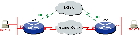
Configurations
| Router 1 |
|---|
ROUTER1# ! hostname ROUTER1 ! username ROUTER2 password same isdn switch-type basic-dms100 ! interface Ethernet 0 ip address 172.16.15.1 255.255.255.248 ! interface serial 0 ip address 172.16.24.129 255.255.255.128 encapsulation FRAME-RELAY ! interface BRI0 description Backup ISDN for frame-relay ip address 172.16.12.1 255.255.255.128 encapsulation PPP dialer idle-timeout 240 dialer wait-for-carrier-time 60 dialer map IP 172.16.12.2 name ROUTER2 broadcast 7086639706 ppp authentication chap dialer-group 1 isdn spid1 0127280320 2728032 isdn spid2 0127295120 2729512 ! router igrp 1 network 172.16.0.0 ! ip route 172.16.15.16 255.255.255.248 172.16.12.2 150 !--- Floating static route. ! access-list 101 deny igrp 0.0.0.0 255.255.255.255 0.0.0.0 255.255.255.255 access-list 101 permit ip 0.0.0.0 255.255.255.255 0.0.0.0 255.255.255.255 dialer-list 1 LIST 101 ! |
| Router 2 |
|---|
ROUTER2# ! hostname ROUTER2 ! username ROUTER1 password same isdn switch-type basic-dms100 ! interface Ethernet 0 ip address 172.16.15.17 255.255.255.248 ! interface Serial 0 ip address 172.16.24.130 255.255.255.128 encapsulation FRAME-RELAY ! interface BRI0 description ISDN backup interface for frame-relay ip address 172.16.12.2 255.255.255.128 encapsulation PPP dialer idle-timeout 240 dialer map IP 172.16.12.1 name ROUTER1 broadcast ppp authentication chap pulse-time 1 dialer-group 1 isdn spid1 0191933333 4445555 isdn spid2 0191933334 4445556 ! router igrp 1 network 172.16.0.0 ! ip route 172.16.15.0 255.255.255.248 172.16.12.1 150 !--- Floating static route. ! access-list 101 deny igrp 0.0.0.0 255.255.255.255 0.0.0.0 255.255.255.255 access-list 101 permit ip 0.0.0.0 255.255.255.255 162.27.9.0 0.0.0.255 dialer-list 1 LIST 101 ! |
show Commands
To verify if the ISDN is working, use the following debug commands. Before issuing debug commands, please see Important Information on Debug Commands.
-
debug isdn q931
-
debug ppp neg
-
debug ppp auth
Try to make an ISDN call from the calling side to the central side without the backup commands. If this is successful, add the backup commands to the calling side.
Note: To test the backup, do not use the shutdown command on the serial interface but emulate a real serial line problem by pulling out the cable from the serial line.
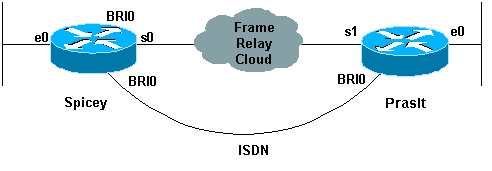
Configuration Per DCLI Backup
Now let's assume that Spicey is the central side and that Prasit is the side making connections to the central side (Spicey). Take care that you only add the backup commands to the side that is calling the central side.
Note: Backup load is not supported on subinterfaces. As we do not track traffic levels on subinterfaces, no load is calculated.
Network Diagram
Configurations
| Spicey |
|---|
Spicey#show running-config Building configuration... Current configuration : 1438 bytes ! version 12.1 service timestamps debug datetime msec service timestamps log datetime msec no service password-encryption ! hostname Spicey ! ! username Prasit password 0 cisco ! ! isdn switch-type basic-net3 ! ! ! interface Ethernet0 ip address 124.124.124.1 255.255.255.0 ! interface Serial0 no ip address encapsulation frame-relay ! interface Serial0.1 point-to-point ip address 4.0.1.1 255.255.255.0 frame-relay interface-dlci 140 ! interface BRI0 ip address 3.1.6.1 255.255.255.0 encapsulation ppp dialer map ip 3.1.6.2 name Prasit broadcast dialer-group 1 isdn switch-type basic-net3 no peer default ip address no cdp enable ppp authentication chap ! router igrp 2 network 3.0.0.0 network 4.0.0.0 network 124.0.0.0 ! ip classless ip route 123.123.123.0 255.255.255.0 3.1.6.2 250 ! access-list 101 deny igrp any any access-list 101 permit ip any any dialer-list 1 protocol ip list 101 ! line con 0 exec-timeout 0 0 transport input none line aux 0 line vty 0 4 login ! end |
| Prasit |
|---|
Prasit#show running-config Building configuration... Current configuration : 1245 bytes ! version 12.1 service timestamps debug datetime msec service timestamps log datetime msec no service password-encryption ! hostname Prasit ! username Spicey password 0 cisco ! ! isdn switch-type basic-net3 ! ! ! interface Ethernet0 ip address 123.123.123.1 255.255.255.0 ! interface Serial1 no ip address encapsulation frame-relay ! interface Serial1.1 point-to-point backup delay 5 10 backup interface BRI0 ip address 4.0.1.2 255.255.255.0 frame-relay interface-dlci 150 ! interface BRI0 ip address 3.1.6.2 255.255.255.0 encapsulation ppp dialer map ip 3.1.6.1 name Spicey broadcast 6106 dialer-group 1 isdn switch-type basic-net3 ppp authentication chap ! router igrp 2 network 3.0.0.0 network 4.0.0.0 network 123.0.0.0 ! ip route 124.124.124.0 255.255.255.0 3.1.6.1 250 ! access-list 101 deny igrp any any access-list 101 permit ip any any dialer-list 1 protocol ip list 101 ! line con 0 exec-timeout 0 0 transport input none line aux 0 line vty 0 4 login ! end |
show Commands
-
show frame-relay map
-
show ip route
-
show isdn history
-
show isdn status
-
show interface bri 0
-
show isdn active
Spicey
Spicey#show frame-relay map
   Serial0.2 (up): point-to-point dlci, dlci 130(0x82,0x2020), broadcast
             status defined, active
   Serial0.1 (up): point-to-point dlci, dlci 140(0x8C,0x20C0), broadcast
             status defined, active

   Spicey#show ip route
   Codes: C - connected, S - static, I - IGRP, R - RIP, M - mobile, B - BGP
          D - EIGRP, EX - EIGRP external, O - OSPF, IA - OSPF inter area
          N1 - OSPF NSSA external type 1, N2 - OSPF NSSA external type 2
          E1 - OSPF external type 1, E2 - OSPF external type 2, E - EGP
          i - IS-IS, L1 - IS-IS level-1, L2 - IS-IS level-2, ia - IS-IS
   inter area
          * - candidate default, U - per-user static route, o - ODR
          P - periodic downloaded static route

   Gateway of last resort is not set

        3.0.0.0/24 is subnetted, 2 subnets C
        3.1.3.0 is directly connected, Serial0.2 C
        3.1.6.0 is directly connected, BRI0
        4.0.0.0/24 is subnetted, 1 subnets C
        4.0.1.0 is directly connected, Serial0.1
        124.0.0.0/24 is subnetted, 1 subnets C
        124.124.124.0 is directly connected, Ethernet0
        123.0.0.0/8 is variably subnetted, 2 subnets, 2 masks I
        123.0.0.0/8 [100/8576] via 4.0.1.2, 00:00:00, Serial0.1 S
        123.123.123.0/24 [250/0] via 3.1.6.2 I
        122.0.0.0/8 [100/8576] via 3.1.3.3, 00:00:37, Serial0.2

   Spicey#
   *Mar  1 00:59:12.527: %LINK-3-UPDOWN: Interface BRI0:1, changed state to up
   *Mar  1 00:59:13.983: %LINEPROTO-5-UPDOWN: Line protocol on Interface
   BRI0:1, changed state to up
   *Mar  1 00:59:18.547: %ISDN-6-CONNECT: Interface BRI0:1 is now connected to 6105 Prasit

   Spicey#show isdn history
   --------------------------------------------------------------------------------
                                      ISDN CALL HISTORY
   --------------------------------------------------------------------------------
   Call History contains all active calls, and a maximum of 100 inactive calls.
   Inactive call data will be retained for a maximum of 15 minutes.
   --------------------------------------------------------------------------------
   Call    Calling      Called          Remote  Seconds Seconds Seconds
   Charges
   Type    Number       Number          Name    Used    Left    Idle  Units/Currency
   --------------------------------------------------------------------------------
   In         6105           6106       Prasit          31      90     29
   --------------------------------------------------------------------------------

   Spicey#
   *Mar  1 01:01:14.547: %ISDN-6-DISCONNECT: Interface BRI0:1  disconnected
   from 6105 Prasit, call lasted 122 seconds
   *Mar  1 01:01:14.663: %LINK-3-UPDOWN: Interface BRI0:1, changed state to down
   *Mar  1 01:01:15.663: %LINEPROTO-5-UPDOWN: Line protocol on Interface
   BRI0:1, changed state to down
Prasit
Prasit#show frame-relay map
   Serial1.1 (up): point-to-point dlci, dlci 150(0x96,0x2460), broadcast
             status defined, active

   Prasit#ping 124.124.124.1

   Type escape sequence to abort.
   Sending 5, 100-byte ICMP Echos to 124.124.124.1, timeout is 2 seconds:
   !!!!!
   Success rate is 100 percent (5/5), round-trip min/avg/max = 36/36/40 ms

   Prasit#show ip route
   Codes: C - connected, S - static, I - IGRP, R - RIP, M - mobile, B - BGP
          D - EIGRP, EX - EIGRP external, O - OSPF, IA - OSPF inter area
          N1 - OSPF NSSA external type 1, N2 - OSPF NSSA external type 2
          E1 - OSPF external type 1, E2 - OSPF external type 2, E - EGP
          i - IS-IS, L1 - IS-IS level-1, L2 - IS-IS level-2, ia - IS-IS
   inter area
          * - candidate default, U - per-user static route, o - ODR
          P - periodic downloaded static route

   Gateway of last resort is not set

   I    3.0.0.0/8 [100/10476] via 4.0.1.1, 00:00:55, Serial1.1
        4.0.0.0/24 is subnetted, 1 subnets
   C    4.0.1.0 is directly connected, Serial1.1
        124.0.0.0/8 is variably subnetted, 2 subnets, 2 masks
   S    124.124.124.0/24 [250/0] via 3.1.6.1
   I    124.0.0.0/8 [100/8576] via 4.0.1.1, 00:00:55, Serial1.1
        123.0.0.0/24 is subnetted, 1 subnets
   C    123.123.123.0 is directly connected, Ethernet0
   I    122.0.0.0/8 [100/10576] via 4.0.1.1, 00:00:55, Serial1.1
The serial line goes down.
Prasit#
   *Mar  1 01:23:50.531: %LINK-3-UPDOWN: Interface Serial1, changed state to down
   *Mar  1 01:23:51.531: %LINEPROTO-5-UPDOWN: Line protocol on Interface
   Serial1, changed state to down
   *Mar  1 01:23:53.775: %LINK-3-UPDOWN: Interface BRI0:1, changed state to down
   *Mar  1 01:23:53.791: %LINK-3-UPDOWN: Interface BRI0:2, changed state to down
   *Mar  1 01:23:53.827: %LINK-3-UPDOWN: Interface BRI0, changed state to up
   *Mar  1 01:23:57.931: %ISDN-6-LAYER2UP: Layer 2 for Interface BR0, TEI 64 changed to up

   Prasit#show ip route
   Codes: C - connected, S - static, I - IGRP, R - RIP, M - mobile, B - BGP
          D - EIGRP, EX - EIGRP external, O - OSPF,IA - OSPF inter area
          N1 - OSPF NSSA external type 1, N2 - OSPF NSSA external type 2
          E1 - OSPF external type 1, E2 - OSPF external type 2, E - EGP
          i - IS-IS, L1 - IS-IS level-1, L2 - IS-IS level-2, ia - IS-IS
   inter area
          * - candidate default, U - per-user static route, o - ODR
          P - periodic downloaded static route

   Gateway of last resort is not set

        3.0.0.0/24 is subnetted, 1 subnets
   C    3.1.6.0 is directly connected, BRI0
        124.0.0.0/24 is subnetted, 1 subnets
   S    124.124.124.0 [250/0] via 3.1.6.1
        123.0.0.0/24 is subnetted, 1 subnets
   C    123.123.123.0 is directly connected, Ethernet0

   Prasit#show isdn status
   Global ISDN Switchtype = basic-net3
   ISDN BRI0 interface
           dsl 0, interface ISDN Switchtype = basic-net3
       Layer 1 Status:
           ACTIVE
       Layer 2 Status:
           TEI = 64, Ces = 1, SAPI = 0, State = MULTIPLE_FRAME_ESTABLISHED
       Layer 3 Status:
           0 Active Layer 3 Call(s)
       Active dsl 0 CCBs = 0
       The Free Channel Mask:  0x80000003
       Total Allocated ISDN CCBs = 0

   Prasit#ping 124.124.124.1

   Type escape sequence to abort.
   Sending 5, 100-byte ICMP Echos to 124.124.124.1, timeout is 2 seconds:
   !
   *Mar  1 01:25:47.383: %LINK-3-UPDOWN: Interface BRI0:1, changed state to up!!!
   Success rate is 80 percent (4/5), round-trip min/avg/max = 36/36/36 ms
   Prasit#
   *Mar  1 01:25:48.475: %LINEPROTO-5-UPDOWN: Line protocol on Interface
   BRI0:1, changed state to up

   Prasit#
   *Mar  1 01:25:53.407: %ISDN-6-CONNECT: Interface BRI0:1 is now connected
   to 6106 Spicey

   Prasit#show isdn status
   Global ISDN Switchtype = basic-net3
   ISDN BRI0 interface
           dsl 0, interface ISDN Switchtype = basic-net3
       Layer 1 Status:
           ACTIVE
       Layer 2 Status:
           TEI = 64, Ces = 1, SAPI = 0, State = MULTIPLE_FRAME_ESTABLISHED
       Layer 3 Status:
           1 Active Layer 3 Call(s)
           CCB:callid=8003, sapi=0, ces=1, B-chan=1, calltype=DATA
       Active dsl 0 CCBs = 1
       The Free Channel Mask: 0x80000002
       Total Allocated ISDN CCBs = 1

   Prasit#show isdn active
   --------------------------------------------------------------------------------
                                      ISDN ACTIVE CALLS
   --------------------------------------------------------------------------------
   Call    Calling      Called          Remote  Seconds Seconds Seconds Charges
   Type    Number       Number          Name    Used    Left    Idle    Units/Currency
   --------------------------------------------------------------------------------
   Out                   6106         Spicey      21     100      19       0
   --------------------------------------------------------------------------------

   Prasit#
   *Mar  1 01:27:49.027: %ISDN-6-DISCONNECT: Interface BRI0:1  disconnected
   from 6106 Spicey, call lasted 121 seconds
   *Mar  1 01:27:49.131: %LINK-3-UPDOWN: Interface BRI0:1, changed state to down
   *Mar  1 01:27:50.131: %LINEPROTO-5-UPDOWN: Line protocol on Interface
   BRI0:1, changed state to down
   *Mar  1 01:28:09.215: %LINK-3-UPDOWN: Interface Serial1, changed state to up
   *Mar  1 01:28:10.215: %LINEPROTO-5-UPDOWN: Line protocol on Interface
   Serial1, changed state to up
   *Mar  1 01:28:30.043: %ISDN-6-LAYER2DOWN: Layer 2 for Interface BRI0,
   TEI 64 changed to down
   *Mar  1 01:28:30.047: %ISDN-6-LAYER2DOWN: Layer 2 for Interface BR0, TEI
   64 changed to down
   *Mar  1 01:28:30.371: %LINK-5-CHANGED: Interface BRI0, changed state to standby mode
   *Mar  1 01:28:30.387: %LINK-3-UPDOWN: Interface BRI0:1, changed state to down
   *Mar  1 01:28:30.403: %LINK-3-UPDOWN: Interface BRI0:2, changed state to down
   Prasit#
The serial connection is back again..
Prasit#show isdn status
   Global ISDN Switchtype = basic-net3
   ISDN BRI0 interface
           dsl 0, interface    ISDN Switchtype = basic-net3
       Layer 1 Status:
           DEACTIVATED
       Layer 2 Status:
           Layer 2 NOT Activated
       Layer 3 Status:
           0 Active Layer    3 Call(s)
       Active dsl 0 CCBs = 0
       The Free Channel Mask:  0x80000003
       Total Allocated ISDN CCBs = 0

   Prasit#show interface bri 0
   BRI0 is standby mode, line protocol is down
     Hardware is BRI
     Internet address is 3.1.6.2/24
     MTU 1500 bytes, BW 64 Kbit, DLY 20000 usec,
        reliability 255/255, txload 1/255, rxload 1/255
     Encapsulation PPP, loopback not set
     Last input 00:01:00, output 00:01:00, output hang never
     Last clearing of "show interface" counters 01:28:16
     Input queue: 0/75/0/0 (size/max/drops/flushes); Total output drops: 0
     Queueing strategy: weighted fair
     Output queue: 0/1000/64/0 (size/max total/threshold/drops)
        Conversations  0/1/16 (active/max active/max total)
        Reserved Conversations 0/0 (allocated/max allocated)
     5 minute input rate 0 bits/sec, 0 packets/sec
     5 minute output rate 0 bits/sec, 0 packets/sec
        128 packets input, 601 bytes, 0 no buffer
        Received 0 broadcasts, 0 runts, 0 giants, 0 throttles
        0 input errors, 0 CRC, 0 frame, 0 overrun, 0 ignored, 0 abort
        132 packets output, 687 bytes, 0 underruns
        0 output errors, 0 collisions, 10 interface resets
        0 output buffer failures, 0 output buffers swapped out
        14 carrier transitions

   Prasit#ping 124.124.124.1

   Type escape sequence to abort.
   Sending 5, 100-byte ICMP Echos to 124.124.124.1, timeout is 2 seconds:
   !!!!!
   Success rate is 100 percent (5/5), round-trip min/avg/max = 36/36/36 ms
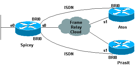
Hub and Spoke with Dialer Profiles
Here is an example of a hub and spoke per DLCI backup configuration. The spoke routers are calling the hub router. As you can see, we allow only one B channel per side by using the max-link option on the dialer pool on the hub side.
Note: Backup load is not supported on subinterfaces. As we do not track traffic levels on subinterfaces, no load is calculated.
Network Diagram
Configurations
| Aton |
|---|
Aton#show running-config Building configuration... Current configuration: ! version 12.0 service timestamps debug uptime service timestamps log uptime no service password-encryption ! hostname Aton ! ! username Spicey password 0 cisco ! isdn switch-type basic-net3 ! ! ! interface Ethernet0 ip address 122.122.122.1 255.255.255.0 ! ! interface Serial1 no ip address encapsulation frame-relay ! interface Serial1.1 point-to-point ip address 3.1.3.3 255.255.255.0 backup delay 5 10 backup interface BRI0 frame-relay interface-dlci 160 ! interface BRI0 ip address 155.155.155.3 255.255.255.0 encapsulation ppp no ip route-cache no ip mroute-cache dialer map ip 155.155.155.2 name Spicey broadcast 6106 dialer-group 1 isdn switch-type basic-net3 ppp authentication chap ! router igrp 2 network 3.0.0.0 network 122.0.0.0 network 155.155.0.0 ! ip route 124.124.124.0 255.255.255.0 155.155.155.2 250 ! access-list 101 deny igrp any any access-list 101 permit ip any any dialer-list 1 protocol ip list 101 ! line con 0 exec-timeout 0 0 transport input none line aux 0 line vty 0 4 login ! end |
| Spicey |
|---|
Spicey#show running-config Building configuration... Current configuration : 1887 bytes ! version 12.1 service timestamps debug datetime msec service timestamps log datetime msec no service password-encryption ! hostname Spicey ! username Prasit password 0 cisco username Aton password 0 cisco ! isdn switch-type basic-net3 ! ! ! interface Ethernet0 ip address 124.124.124.1 255.255.255.0 ! interface Serial0 no ip address encapsulation frame-relay ! interface Serial0.1 point-to-point ip address 4.0.1.1 255.255.255.0 frame-relay interface-dlci 140 ! interface Serial0.2 point-to-point ip address 3.1.3.1 255.255.255.0 frame-relay interface-dlci 130 ! interface BRI0 no ip address encapsulation ppp no ip route-cache no ip mroute-cache dialer pool-member 2 max-link 1 dialer pool-member 1 max-link 1 isdn switch-type basic-net3 no peer default ip address no cdp enable ppp authentication chap ! interface Dialer1 ip address 160.160.160.1 255.255.255.0 encapsulation ppp no ip route-cache no ip mroute-cache dialer pool 1 dialer remote-name Prasit dialer-group 1 ppp authentication chap ! interface Dialer2 ip address 155.155.155.2 255.255.255.0 encapsulation ppp no ip route-cache no ip mroute-cache dialer pool 2 dialer remote-name Aton dialer-group 1 ppp authentication chap ! router igrp 2 network 3.0.0.0 network 4.0.0.0 network 124.0.0.0 network 155.155.0.0 network 160.160.0.0 ! access-list 101 deny igrp any any access-list 101 permit ip any any dialer-list 1 protocol ip list 101 ! line con 0 exec-timeout 0 0 transport input none line aux 0 line vty 0 4 login ! end |
| Prasit |
|---|
Prasit#show running-config Building configuration... Current configuration : 1267 bytes ! version 12.1 service timestamps debug datetime msec service timestamps log datetime msec no service password-encryption ! hostname Prasit ! username Spicey password 0 cisco ! isdn switch-type basic-net3 ! ! ! interface Ethernet0 ip address 123.123.123.1 255.255.255.0 ! interface Serial1 no ip address encapsulation frame-relay ! interface Serial1.1 point-to-point backup delay 5 10 backup interface BRI0 ip address 4.0.1.2 255.255.255.0 frame-relay interface-dlci 150 ! interface BRI0 ip address 160.160.160.2 255.255.255.0 encapsulation ppp dialer map ip 160.160.160.1 name Spicey broadcast 6106 dialer-group 1 isdn switch-type basic-net3 ppp authentication chap ! router igrp 2 network 4.0.0.0 network 123.0.0.0 network 160.160.0.0 ! ip route 124.124.124.0 255.255.255.0 160.160.160.1 250 ! access-list 101 deny igrp any any access-list 101 permit ip any any dialer-list 1 protocol ip list 101 ! line con 0 exec-timeout 0 0 transport input none line aux 0 line vty 0 4 login ! end |
show Commands
-
show frame-relay map
-
show ip route
-
show frame map
-
show frame-relay pvc
Aton
Aton#show frame-relay map
   Serial1.1 (up): point-to-point dlci, dlci 160(0xA0,0x2800), broadcast
             status defined, active

   Aton#ping 124.124.124.1
   Type escape sequence to abort.
   Sending 5, 100-byte ICMP Echos to 124.124.124.1, timeout is 2 seconds:
   !!!!!
   Success rate is 100 percent (5/5), round-trip min/avg/max = 36/36/36 ms

   Aton#show ip route
   Codes: C - connected, S - static, I - IGRP, R - RIP, M - mobile, B - BGP
          D - EIGRP, EX - EIGRP external, O - OSPF,    IA - OSPF inter area
          N1 - OSPF NSSA external type 1, N2 - OSPF    NSSA external type 2
          E1 - OSPF external type 1, E2 - OSPF external type 2, E - EGP
          i - IS-IS, L1 - IS-IS level-1, L2 - IS-IS level-2, * - candidate default
          U - per-user static route, o - ODR, P - periodic downloaded static route
          T - traffic engineered route

   Gateway of last resort is not set

   I    155.155.0.0/16 [100/182571] via 3.1.3.1, Serial1.1
        3.0.0.0/24 is subnetted, 1 subnets
   C    3.1.3.0 is directly connected, Serial1.1
   I    4.0.0.0/8 [100/10476] via 3.1.3.1, Serial1.1
   I    160.160.0.0/16 [100/182571] via 3.1.3.1, Serial1.1
        124.0.0.0/8 is variably subnetted, 2 subnets, 2 masks
   S    124.124.124.0/24 [250/0] via 155.155.155.2
   I    124.0.0.0/8 [100/8576] via 3.1.3.1, Serial1.1
   I    123.0.0.0/8 [100/10576] via 3.1.3.1, Serial1.1
        122.0.0.0/24 is subnetted, 1 subnets
   C    122.122.122.0 is directly connected, Ethernet0
   Aton#
Serial 1 is going down.
Aton#
   01:16:33: %LINK-3-UPDOWN: Interface Serial1, changed state to down
   01:16:34: %LINEPROTO-5-UPDOWN: Line protocol on Interface Serial1,
   changed state to down
   01:16:37: %LINK-3-UPDOWN: Interface BRI0:1, changed state to down
   01:16:37: %LINK-3-UPDOWN: Interface BRI0:2, changed state to down
   01:16:37: %LINK-3-UPDOWN: Interface BRI0, changed state to up
   01:16:41: %ISDN-6-LAYER2UP: Layer 2 for Interface BR0, TEI 64 changed to up

   Aton#show ip route
   Codes: C - connected, S - static, I - IGRP, R - RIP, M - mobile, B - BGP
          D - EIGRP, EX - EIGRP external, O - OSPF, IA - OSPF inter area
          N1 - OSPF NSSA external type 1, N2 - OSPF NSSA external type 2
          E1 - OSPF external type 1, E2 - OSPF external    type 2, E - EGP
          i - IS-IS, L1 - IS-IS level-1, L2 - IS-IS level-2, * - candidate default
          U - per-user static route, o - ODR, P - periodic downloaded static route
          T - traffic engineered route

   Gateway of last resort is not set
        155.155.0.0/24 is subnetted, 1 subnets
   C    155.155.155.0 is directly connected, BRI0
        124.0.0.0/24 is subnetted, 1 subnets
   S    124.124.124.0 [250/0] via 155.155.155.2
        122.0.0.0/24 is subnetted, 1 subnets
   C    122.122.122.0 is directly connected, Ethernet0

   Aton#ping 124.124.124.1
   Type escape sequence to abort.
   Sending 5, 100-byte ICMP Echos to 124.124.124.1, timeout is 2 seconds:

   01:21:33: %LINK-3-UPDOWN: Interface BRI0:1, changed state to up.!!!!
   Success rate is 80 percent (4/5), round-trip min/avg/max = 36/36/36 ms
   Aton#
   01:21:34: %LINEPROTO-5-UPDOWN: Line protocol on Interface BRI0:1,
   changed state to up
   01:21:39: %ISDN-6-CONNECT: Interface BRI0:1 is now connected to 6106
   Spicey

   Aton#ping 124.124.124.1

   Type escape sequence to abort.
   Sending 5, 100-byte ICMP Echos to 124.124.124.1, timeout is 2 seconds:
   !!!!!
   Success rate is 100 percent (5/5), round-trip min/avg/max = 32/123/296 ms
   Aton#
Serial 1 becomes active again
Aton#
   01:24:02: %ISDN-6-DISCONNECT: Interface BRI0:1  disconnected from 6106
   Spicey, call lasted 149 seconds
   01:24:02: %LINK-3-UPDOWN: Interface BRI0:1, changed state to down
   01:24:03: %LINEPROTO-5-UPDOWN: Line protocol on Interface BRI0:1,
   changed state to down

   Aton#show frame map
   Serial1.1 (down): point-to-point dlci, dlci 160(0xA0,0x2800), broadcast
             status deleted
   Aton#
   01:26:35: %LINK-3-UPDOWN: Interface Serial1, changed state to up
   01:26:36: %LINEPROTO-5-UPDOWN: Line protocol on Interface Serial1,
   changed state to up
   01:26:56: %ISDN-6-LAYER2DOWN: Layer 2 for Interface BRI0, TEI 64 changed
   to down
   01:26:56: %ISDN-6-LAYER2DOWN: Layer 2 for Interface BR0, TEI 64 changed
   to down
   01:26:56: %LINK-5-CHANGED: Interface BRI0, changed state to standby mode
   01:26:56: %LINK-3-UPDOWN: Interface BRI0:1, changed state to down
   01:26:56: %LINK-3-UPDOWN: Interface BRI0:2, changed state to down

   Aton#show frame map
   Serial1.1 (up): point-to-point dlci, dlci 160(0xA0,0x2800), broadcast
             status defined, active
   Aton#ping 124.124.124.1

   Type escape sequence to abort.
   Sending 5, 100-byte ICMP Echos to 124.124.124.1, timeout is 2 seconds:
   !!!!!
   Success rate is 100 percent (5/5), round-trip min/avg/max = 36/36/36 ms

   Aton#ping 124.124.124.1

   Aton#show frame-relay pvc
   PVC Statistics for interface Serial1 (Frame Relay DTE)
                    Active     Inactive      Deleted          Static
     Local          1               0            0               0
     Switched       0               0            0               0
     Unused         0               0            0               0

   DLCI = 160, DLCI USAGE = LOCAL, PVC STATUS = ACTIVE, INTERFACE =
   Serial1.1
     input pkts 60               output pkts 69           in    bytes 9694
     out bytes 10811             dropped pkts 0           in    FECN pkts 0
     in BECN pkts 0              out FECN pkts 0          out BECN pkts 0
     in DE pkts 0                out DE pkts 0
     out bcast pkts 44         out    bcast bytes 7565
     pvc create time 01:28:35, last time pvc status changed 00:02:19
Spicey
Spicey#show frame-relay map
   Serial0.1 (up): point-to-point dlci, dlci 140(0x8C,0x20C0), broadcast
             status defined, active
   Serial0.2 (up): point-to-point dlci, dlci 130(0x82,0x2020), broadcast
             status defined, active

   Spicey#ping 122.122.122.1
   Type escape sequence to abort.
   Sending 5, 100-byte ICMP Echos to 122.122.122.1, timeout is 2 seconds:
   !!!!!
   Success rate is 100 percent (5/5), round-trip min/avg/max = 32/35/36 ms

   Spicey#ping 123.123.123.1
   Type escape sequence to abort.
   Sending 5, 100-byte ICMP Echos to 123.123.123.1, timeout is 2 seconds:
   !!!!!
   Success rate is 100 percent (5/5), round-trip min/avg/max = 36/36/36 ms

   Spicey#show ip route
   Codes: C - connected, S - static, I - IGRP, R - RIP, M - mobile, B - BGP
          D - EIGRP, EX - EIGRP external, O - OSPF,    IA - OSPF inter area
          N1 - OSPF NSSA external type 1, N2 - OSPF    NSSA external type 2
          E1 - OSPF external type 1, E2 - OSPF external    type 2, E - EGP
          i - IS-IS, L1 - IS-IS level-1, L2 - IS-IS    level-2, ia - IS-IS
   inter area
          * - candidate default, U - per-user static    route, o - ODR
          P - periodic downloaded static route
   Gateway of last resort is not set
        155.155.0.0/24 is subnetted, 1 subnets
   C    155.155.155.0 is directly connected, Dialer2
        3.0.0.0/24 is subnetted, 1 subnets
   C    3.1.3.0 is directly connected, Serial0.2
        4.0.0.0/24 is subnetted, 1 subnets
   C    4.0.1.0 is directly connected, Serial0.1
        160.160.0.0/24 is subnetted, 1 subnets
   C    160.160.160.0 is directly connected, Dialer1
        124.0.0.0/24 is subnetted, 1 subnets
   C    124.124.124.0 is directly connected, Ethernet0
   I    123.0.0.0/8 [100/8576] via 4.0.1.2, 00:00:55, Serial0.1
   I    122.0.0.0/8 [100/8576] via 3.1.3.3, 00:00:35, Serial0.2
Both serial lines from the calling sides are going down.
Spicey#

   *Mar  1 01:21:30.171: %LINK-3-UPDOWN: Interface BRI0:1, changed state toup
   *Mar  1 01:21:30.627: %DIALER-6-BIND: Interface BR0:1 bound to profile Di2
   *Mar  1 01:21:31.647: %LINEPROTO-5-UPDOWN: Line protocol on Interface
   BRI0:1, changed state to up
   *Mar  1 01:21:36.191: %ISDN-6-CONNECT: Interface BRI0:1 is now connected
   to 6104 Aton
   *Mar  1 01:21:40.923: %LINK-3-UPDOWN: Interface BRI0:2, changed state to up
   *Mar  1 01:21:41.359: %DIALER-6-BIND: Interface BR0:2 bound to profile Di1
   *Mar  1 01:21:42.383: %LINEPROTO-5-UPDOWN: Line protocol on Interface
   BRI0:2, changed state to up
   *Mar  1 01:21:46.943: %ISDN-6-CONNECT: Interface BRI0:2 is now connected
   to 6105 Prasit
   *Mar  1 01:23:59.819: %DIALER-6-UNBIND: Interface BR0:1 unbound from
   profile Di2
   *Mar  1 01:23:59.831: %ISDN-6-DISCONNECT: Interface BRI0:1  disconnected
   from 6104 Aton, call lasted 149 seconds
   *Mar  1 01:23:59.927: %LINK-3-UPDOWN: Interface BRI0:1, changed state to down
   *Mar  1 01:24:00.923: %LINEPROTO-5-UPDOWN: Line protocol on Interface
   BRI0:1, changed state to down
   *Mar  1 01:24:03.015: %DIALER-6-UNBIND: Interface BR0:2 unbound from
   profile Di1
   *Mar  1 01:24:03.023: %ISDN-6-DISCONNECT: Interface BRI0:2  disconnected
   from 6105 Prasit, call lasted 142 seconds
   *Mar  1 01:24:03.107: %LINK-3-UPDOWN: Interface BRI0:2, changed state to down
   *Mar  1 01:24:04.107: %LINEPROTO-5-UPDOWN: Line protocol on Interface
   BRI0:2, changed state to down

   Spicey#show frame map
   Serial0.1 (down): point-to-point dlci, dlci 140(0x8C,0x20C0), broadcast
             status defined, inactive
   Serial0.2 (down): point-to-point dlci, dlci 130(0x82,0x2020), broadcast
             status defined, inactive
   Spicey#
Both serial lines are available again.
Spicey#show frame pvc
   PVC Statistics for interface Serial0 (Frame Relay DTE)
                    Active     Inactive      Deleted          Static
     Local          2               0            0               0
     Switched       0               0            0               0
     Unused         0               0            0               0

   DLCI = 130, DLCI USAGE = LOCAL, PVC STATUS = ACTIVE, INTERFACE =
   Serial0.2

     input pkts 54               output pkts 61           in    bytes 7014
     out bytes 9975              dropped pkts 3           in    FECN pkts 0
     in BECN pkts 0              out FECN pkts 0          out BECN    pkts 0
     in DE pkts 0                out DE pkts 0
     out bcast pkts 40         out    bcast bytes 7803
     pvc create time 01:28:14, last time pvc status changed 00:02:38

   DLCI = 140, DLCI USAGE = LOCAL, PVC STATUS = ACTIVE, INTERFACE =
   Serial0.1

     input pkts 56               output pkts 60           in    bytes 7604
     out bytes 10114             dropped pkts 2           in    FECN pkts 0
     in BECN pkts 0              out FECN pkts 0          out BECN    pkts 0
     in DE pkts 0                out DE pkts 0
     out bcast pkts 39           out    bcast bytes 7928
     pvc create time 01:28:15, last time pvc status changed 00:02:29
Prasit
Prasit#show frame-relay map
   Serial1.1 (up): point-to-point dlci, dlci 150(0x96,0x2460), broadcast
             status defined, active

   Prasit#ping 124.124.124.1
   Type escape sequence to abort.
   Sending 5, 100-byte ICMP Echos to 124.124.124.1, timeout is 2 seconds:
   !!!!!
   Success rate is 100 percent (5/5), round-trip min/avg/max = 36/36/40 ms

   Prasit#show ip route
   Codes: C - connected, S - static, I - IGRP, R - RIP, M - mobile, B - BGP
          D - EIGRP, EX - EIGRP external, O - OSPF,    IA - OSPF inter area
          N1 - OSPF NSSA external type 1, N2 - OSPF    NSSA external type 2
          E1 - OSPF external type 1, E2 - OSPF external    type 2, E - EGP
          i - IS-IS, L1 - IS-IS level-1, L2 - IS-IS    level-2, ia - IS-IS
   inter area
          * - candidate default, U - per-user static    route, o - ODR
          P - periodic downloaded static route

   Gateway of last resort is not set

   I    155.155.0.0/16 [100/182571] via 4.0.1.1, 00:00:41, Serial1.1
   I    3.0.0.0/8 [100/10476] via 4.0.1.1, 00:00:41, Serial1.1
        4.0.0.0/24 is subnetted, 1 subnets
   C    4.0.1.0 is directly connected, Serial1.1
   I    160.160.0.0/16 [100/182571] via 4.0.1.1, 00:00:41, Serial1.1
        124.0.0.0/8 is variably subnetted, 2 subnets, 2 masks
   S    124.124.124.0/24 [250/0] via 160.160.160.1
   I    124.0.0.0/8 [100/8576] via 4.0.1.1, 00:00:41, Serial1.1
        123.0.0.0/24 is subnetted, 1 subnets
   C    123.123.123.0 is directly connected, Ethernet0
   I    122.0.0.0/8 [100/10576] via 4.0.1.1, 00:00:42, Serial1.1
   Prasit#
Serial 1 goes down.
Prasit#
   *Mar  1 01:16:08.287: %LINK-3-UPDOWN: Interface Serial1, changed state to down
   *Mar  1 01:16:09.287: %LINEPROTO-5-UPDOWN: Line protocol on Interface
   Serial1, changed state to down
   *Mar  1 01:16:11.803: %LINK-3-UPDOWN: Interface BRI0:1, changed state to down
   *Mar  1 01:16:11.819: %LINK-3-UPDOWN: Interface BRI0:2, changed state to down
   *Mar  1 01:16:11.855: %LINK-3-UPDOWN: Interface BRI0, changed state to up
   *Mar  1 01:16:15.967: %ISDN-6-LAYER2UP: Layer 2 for Interface BR0, TEI
   64 changed to up

   Prasit#show ip route
   Codes: C - connected, S - static, I - IGRP, R - RIP, M - mobile, B - BGP
          D - EIGRP, EX - EIGRP external, O - OSPF,    IA - OSPF inter area
          N1 - OSPF NSSA external type 1, N2 - OSPF    NSSA external type 2
          E1 - OSPF external type 1, E2 - OSPF external    type 2, E - EGP
          i - IS-IS, L1 - IS-IS level-1, L2 - IS-IS    level-2, ia - IS-IS
   inter area
          * - candidate default, U - per-user static    route, o - ODR
          P - periodic downloaded static route

   Gateway of last resort is not set

        160.160.0.0/24 is subnetted, 1 subnets
   C    160.160.160.0 is directly connected, BRI0
        124.0.0.0/24 is subnetted, 1 subnets
   S    124.124.124.0 [250/0] via 160.160.160.1
        123.0.0.0/24 is subnetted, 1 subnets
   C    123.123.123.0 is directly connected, Ethernet0

   Prasit#ping 124.124.124.1

   Type escape sequence to abort.
   Sending 5, 100-byte ICMP Echos to 124.124.124.1, timeout is 2 seconds:

   *Mar  1 01:21:38.967: %LINK-3-UPDOWN: Interface BRI0:1, changed state to
   up.!!!!
   Success rate is 80 percent (4/5), round-trip min/avg/max = 36/36/36 ms
   Prasit#
   *Mar  1 01:21:40.063: %LINEPROTO-5-UPDOWN: Line protocol on Interface
   BRI0:1, changed state to up
   *Mar  1 01:21:44.991: %ISDN-6-CONNECT: Interface BRI0:1 is now connected
   to 6106 Spicey

   Prasit#ping 124.124.124.1

   Type escape sequence to abort.
   Sending 5, 100-byte ICMP Echos to 124.124.124.1, timeout is 2 seconds:
   !!!!!
   Success rate is 100 percent (5/5), round-trip min/avg/max = 36/36/36 ms
   Prasit#
Serial 1 becomes active again.
Prasit#

   *Mar  1 01:26:40.579: %LINK-3-UPDOWN: Interface Serial1, changed state to up
   *Mar  1 01:26:41.579: %LINEPROTO-5-UPDOWN: Line protocol on Interface
   Serial1, changed state to up
   *Mar  1 01:27:01.051: %ISDN-6-LAYER2DOWN: Layer 2 for Interface BRI0,
   TEI 64 changed to down
   *Mar  1 01:27:01.055: %ISDN-6-LAYER2DOWN: Layer 2 for Interface BR0, TEI
   64 changed to down
   *Mar  1 01:27:01.363: %LINK-5-CHANGED: Interface BRI0, changed state to standby mode
   *Mar  1 01:27:01.379: %LINK-3-UPDOWN: Interface BRI0:1, changed state to down
   *Mar  1 01:27:01.395: %LINK-3-UPDOWN: Interface BRI0:2, changed state to down

   Prasit#show frame map
   Serial1.1 (up): point-to-point dlci, dlci 150(0x96,0x2460), broadcast
             status defined, active

   Prasit#ping 124.124.124.1
   Type escape sequence to abort.
   Sending 5, 100-byte ICMP Echos to 124.124.124.1, timeout is 2 seconds:
   !!!!!
   Success rate is 100 percent (5/5), round-trip min/avg/max = 36/116/432 ms

   Prasit#show frame-relay pvc
   PVC Statistics for interface Serial1 (Frame Relay DTE)

                    Active     Inactive      Deleted          Static
     Local          1               0            0               0
     Switched       0               0            0               0
     Unused         0               0            0               0

   DLCI = 150, DLCI USAGE = LOCAL, PVC STATUS = ACTIVE, INTERFACE =
   Serial1.1

     input pkts 58               output pkts 66           in    bytes 9727
     out bytes 10022             dropped pkts 0           in    FECN pkts 0
     in BECN pkts 0              out FECN pkts 0          out BECN    pkts 0
     in DE pkts 0                out DE pkts 0
     out bcast pkts 46         out    bcast bytes 7942
     pvc create time 01:27:37, last time pvc status changed 00:01:59
Configuring Frame Relay Switching
Frame Relay switching is a means of switching packets based on the data-link connection identifier (DLCI). We can look on this as the Frame Relay equivalent of a Media Access Control (MAC) address. You perform switching by configuring your Cisco router or access server into a Frame Relay network. There are two parts to a Frame Relay network:
-
Frame Relay data terminal equipment (DTE) - the router or access server.
-
Frame Relay data circuit-terminating equipment (DCE) switch.
Note: In Cisco IOS Software release 12.1(2)T and later, the frame route command has been replaced by the connect command.
Let's look at a sample configuration. In the configuration below, we are using the router America as a Frame Relay switch. We are using Spicey as a hub router and Prasit and Aton as spoke routers. We have connected them as follows:
-
Prasit serial 1 (s1) DTE is connected to America serial 1/4 (s1/4) DCE.
-
Spicey serial 0 (s0) DTE is connected to America serial 1/5 (s1/5) DCE.
-
Aton serial 1 (s1) DTE is connected to America serial 3/4 (s3/4) DCE.
Network Diagram
This document is based on the following configuration:
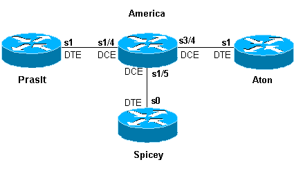
Configurations
| Spicey |
|---|
Spicey#show running-config Building configuration... ! version 12.1 service timestamps debug datetime msec service timestamps log datetime msec no service password-encryption ! hostname Spicey ! ! ! interface Ethernet0 ip address 124.124.124.1 255.255.255.0 ! interface Serial0 ip address 3.1.3.1 255.255.255.0 encapsulation frame-relay frame-relay interface-dlci 130 frame-relay interface-dlci 140 ! ! router rip network 3.0.0.0 network 124.0.0.0 ! line con 0 ! exec-timeout 0 0 transport input none line aux 0 line vty 0 4 login ! end |
| Prasit |
|---|
Prasit#show running-config Building configuration... Current configuration : 1499 bytes ! version 12.1 service timestamps debug datetime msec service timestamps log datetime msec no service password-encryption ! hostname Prasit ! ! ! interface Ethernet0 ip address 123.123.123.1 255.255.255.0 ! interface Serial1 ip address 3.1.3.2 255.255.255.0 encapsulation frame-relay frame-relay interface-dlci 150 ! ! router rip network 3.0.0.0 network 123.0.0.0 ! ! line con 0 exec-timeout 0 0 transport input none line aux 0 line vty 0 4 login ! end |
| Aton |
|---|
Aton#show running-config Building configuration... Current configuration: ! version 12.0 service timestamps debug uptime service timestamps log uptime no service password-encryption ! hostname Aton ! ! ! interface Ethernet0 ip address 122.122.122.1 255.255.255.0 ! interface Serial1 ip address 3.1.3.3 255.255.255.0 encapsulation frame-relay frame-relay interface-dlci 160 ! router rip network 3.0.0.0 network 122.0.0.0 ! ! line con 0 exec-timeout 0 0 transport input none line aux 0 line vty 0 4 login ! end |
| America |
|---|
america#show running-config Building configuration... Current configuration: ! ! service timestamps debug datetime msec service timestamps log datetime msec no service password-encryption ! hostname america ! frame-relay switching ! ! interface Serial1/4 description *** static DCE connection to s1 Prasit no ip address encapsulation frame-relay clockrate 2000000 frame-relay intf-type dce frame-relay route 150 interface Serial1/5 140 ! interface Serial1/5 description *** static DCE connection to s0 spicy no ip address encapsulation frame-relay bandwidth 1000000 tx-queue-limit 100 frame-relay intf-type dce frame-relay route 130 interface Serial3/4 160 frame-relay route 140 interface Serial1/4 150 transmitter-delay 10 ! interface Serial3/4 description *** static DCE connection to s1 Aton encapsulation frame-relay no ip mroute-cache clockrate 2000000 frame-relay intf-type dce frame-relay route 160 interface Serial1/5 130 ! |
show Commands
Use the following show commands to test that your network is operating properly:
-
show frame-relay map
-
show frame-relay pvc
The output shown below is a result of entering these commands on the devices we are using in this sample configuration.
Spicey
Spicey#show frame-relay map
Serial0 (up): ip 3.1.3.2 dlci 140(0x8C,0x20C0), dynamic,
              broadcast,, status defined, active
Serial0 (up): ip 3.1.3.3 dlci 130(0x82,0x2020), dynamic,
              broadcast,, status defined, active

Spicey#show frame-relay pvc

PVC Statistics for interface Serial0 (Frame Relay DTE)
                   Active     Inactive      Deleted            Static
 Local          2                 0            0                 0
 Switched       0                 0            0                 0
 Unused         0                 0            0                 0

 DLCI = 130, DLCI USAGE = LOCAL, PVC STATUS = ACTIVE, INTERFACE = Serial0

  input pkts 32                 output pkts 40                in bytes 3370
  out bytes 3928                dropped pkts 0                in FECN pkts 0
  in BECN pkts 0                out FECN pkts 0               out BECN pkts 0
  in DE pkts 0                  out DE pkts 0
  out bcast pkts 30             out bcast bytes 2888
  pvc create time 00:15:46, last time pvc status changed 00:10:42

DLCI = 140, DLCI USAGE = LOCAL, PVC STATUS = ACTIVE, INTERFACE = Serial0

   input pkts 282                output pkts 291          in bytes 25070
   out bytes 27876               dropped pkts 0           in FECN pkts 0
   in BECN pkts 0                out FECN pkts 0          out BECN pkts 0
   in DE pkts 0                  out DE pkts 0
   out bcast pkts 223            out bcast bytes 20884
   pvc create time 02:28:36, last time pvc status changed 02:25:14
Prasit
Prasit#show frame-relay map
Serial1 (up): ip 3.1.3.1 dlci 150(0x96,0x2460), dynamic,
                   broadcast,, status defined, active

Prasit#show frame-relay pvc

PVC Statistics for interface Serial1 (Frame Relay DTE)
                   Active     Inactive      Deleted            Static
  Local          1                 0            0                 0
  Switched       0                 0            0                 0
  Unused         0                 0            0
DLCI = 150, DLCI USAGE = LOCAL, PVC STATUS = ACTIVE, INTERFACE = Serial1
  input pkts 311                output pkts 233          in bytes 28562
  out bytes 22648               dropped pkts 0           in FECN pkts 0
  in BECN pkts 0                out FECN pkts 0          out BECN pkts 0
  in DE pkts 0                  out DE pkts 0
  out bcast pkts 162            out bcast bytes 15748
  pvc create time 02:31:39, last time pvc status changed 02:25:14
Aton
Aton#show frame-relay map
Serial1 (up): ip 3.1.3.1 dlci 160(0xA0,0x2800), dynamic, broadcast, status defined, active

Aton#show frame-relay pvc
PVC Statistics for interface Serial1 (Frame Relay DTE)
               Active     Inactive      Deleted            Static
Local          1                 0            0                 0
Switched       0                 0            0                 0
Unused         0                 0            0                 0

DLCI = 160, DLCI USAGE = LOCAL, PVC STATUS = ACTIVE, INTERFACE = Serial
 input pkts 35                 output pkts 32                in bytes 3758
 out bytes 3366                dropped pkts 0                in FECN pkt 0
 in BECN pkts 0                out FECN pkts 0               out BECN pkts 0
 in DE pkts 0                  out DE pkts 0
 out bcast pkts 27 out bcast bytes 2846
 pvc create time 00:10:53, last time pvc status changed 00:10:53
Configuring Frame Relay DLCI Prioritization
Data-link connection identifier (DLCI) prioritization is the process whereby different traffic types are placed upon separate DLCIs so that a Frame Relay network can provide a different committed information rate for each traffic type. It can be used in conjunction with either custom queuing or priority queuing to provide bandwidth management control over the access link to the Frame Relay network. In addition, some Frame Relay service providers and Frame Relay switches (such as the Stratacom Internetwork Packet Exchange [IPX], IGX and BPX or AXIS switches) actually provide prioritization within the Frame Relay cloud based on this priority setting.
Implementation Considerations
When implementing DLCI prioritization, please note the following points:
-
If a secondary DLCI goes down, you lose traffic destined for that queue only.
-
If you lose the primary DLCI, the subinterface goes down and you lose all traffic.
Network Diagram
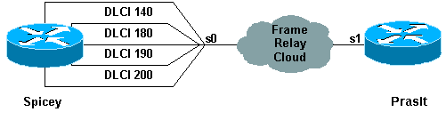
In order to use this setup, you need to have four DLCIs for the side that will use the DLCI prioritization. In this example, we have configured Spicey for priority queueing as follows:
-
Ping is in the high-priority queue.
-
Telnet is in the medium-priority queue.
-
File Transfer Protocol (FTP) is in the normal-priority queue.
-
All other IP traffic is in the low-priority queue.
Note: Make sure you configure the DLCIs to correspond with the priority list, or the system will not use the correct queue.
Configurations
| Spicey |
|---|
Spicey#show running-config Building configuration... Current configuration : 1955 bytes ! version 12.1 service timestamps debug datetime msec service timestamps log datetime msec ! hostname Spicey ! ! interface Ethernet0 ip address 124.124.124.1 255.255.255.0 ! interface Serial0 no ip address encapsulation frame-relay priority-group 1 ! interface Serial0.1 point-to-point ip address 4.0.1.1 255.255.255.0 frame-relay priority-dlci-group 1 140 180 190 200 frame-relay interface-dlci 140 ! router igrp 2 network 4.0.0.0 network 124.0.0.0 ! access-list 102 permit icmp any any priority-list 1 protocol ip high list 102 priority-list 1 protocol ip medium tcp telnet priority-list 1 protocol ip normal tcp ftp priority-list 1 protocol ip low ! line con 0 exec-timeout 0 0 transport input none line aux 0 line vty 0 4 login ! end |
| Prasit |
|---|
Prasit#show running-config Building configuration... ! version 12.1 service timestamps debug datetime msec service timestamps log datetime msec ! hostname Prasit ! ! ! interface Ethernet0 ip address 123.123.123.1 255.255.255.0 ! interface Serial1 ip address 4.0.1.2 255.255.255.0 encapsulation frame-relay ! router igrp 2 network 4.0.0.0 network 123.0.0.0 ! line con 0 exec-timeout 0 0 transport input none line aux 0 line vty 0 4 login ! end |
debug and show Commands
Use the following show and debug commands to test that your network is operating properly. Before issuing debug commands, please see Important Information on Debug Commands.
-
show frame-relay pvc
-
show frame-relay map
-
show queueing priority
-
debug priority
The output shown below is a result of entering these commands on the devices we are using in this sample configuration.
Spicey
Spicey#show frame-relay pvc
PVC Statistics for interface Serial0 (Frame Relay DTE)

              Active     Inactive      Deleted       Static
  Local          4            0            0            0
  Switched       0            0            0            0
  Unused         0            0            0            0

DLCI = 140, DLCI USAGE = LOCAL, PVC STATUS = ACTIVE, INTERFACE = Serial0.1

  input pkts 106           output pkts 15           in bytes 6801
  out bytes 1560           dropped pkts 0           in FECN pkts 0
  in BECN pkts 0           out FECN pkts 0          out BECN pkts 0
  in DE pkts 0             out DE pkts 0
  out bcast pkts 0         out bcast bytes 0
  pvc create time 00:29:22, last time pvc status changed 00:20:37
  Priority DLCI Group 1, DLCI 140 (HIGH), DLCI 180 (MEDIUM)
  DLCI 190 (NORMAL), DLCI 200 (LOW)

DLCI = 180, DLCI USAGE = LOCAL, PVC STATUS = ACTIVE, INTERFACE = Serial0.1

  input pkts 0             output pkts 51           in bytes 0
  out bytes 2434           dropped pkts 0           in FECN pkts 0
  in BECN pkts 0           out FECN pkts 0          out BECN pkts 0
  in DE pkts 0             out DE pkts 0
  out bcast pkts 0         out bcast bytes 0
  pvc create time 00:29:23, last time pvc status changed 00:14:48

DLCI = 190, DLCI USAGE = LOCAL, PVC STATUS = ACTIVE, INTERFACE = Serial0.1

  input pkts 0             output pkts 13           in bytes 0
  out bytes 3653           dropped pkts 0           in FECN pkts 0
  in BECN pkts 0           out FECN pkts 0          out BECN pkts 0
  in DE pkts 0             out DE pkts 0
  out bcast pkts 13        out bcast bytes 3653
  pvc create time 00:29:23, last time pvc status changed 00:14:28

DLCI = 200, DLCI USAGE = LOCAL, PVC STATUS = ACTIVE, INTERFACE = Serial0.1

  input pkts 0             output pkts 42           in bytes 0
  out bytes 2554           dropped pkts 0           in FECN pkts 0
  in BECN pkts 0           out FECN pkts 0          out BECN pkts 0
  in DE pkts 0             out DE pkts 0
  out bcast pkts 10        out bcast bytes 500
  pvc create time 00:29:24, last time pvc status changed 00:14:09

Spicey#show frame-relay map
Serial0.1 (up): point-to-point dlci, dlci 140(0x8C,0x20C0), broadcast
  status defined, active
  Priority DLCI Group 1, DLCI 140 (HIGH), DLCI 180 (MEDIUM)
  DLCI 190 (NORMAL), DLCI 200 (LOW)

Spicey#show queueing priority
Current priority queue configuration:

List   Queue  Args
1      high   protocol ip          list 102
1      medium protocol ip          tcp port telnet
1      normal protocol ip          tcp port ftp
1      low    protocol ip
To verify the priority queue, use the debug priority command.
Spicey#debug priority
Priority output queueing debugging is on

Spicey#ping 123.123.123.1

Type escape sequence to abort.
Sending 5, 100-byte ICMP Echos to 123.123.123.1, timeout is 2 seconds:
!!!!!
Success rate is 100 percent (5/5), round-trip min/avg/max = 44/45/48 ms
Spicey#
*Mar  1 00:32:30.391: PQ: Serial0: ip (s=4.0.1.1, d=123.123.123.1) ->high
*Mar  1 00:32:30.395: PQ: Serial0: ip (s=4.0.1.1, d=123.123.123.1) ->high
*Mar  1 00:32:30.399: PQ: Serial0 output (Pk size/Q 104/0)
*Mar  1 00:32:30.439: PQ: Serial0: ip (s=4.0.1.1, d=123.123.123.1) ->high
*Mar  1 00:32:30.443: PQ: Serial0: ip (s=4.0.1.1, d=123.123.123.1) ->high
*Mar  1 00:32:30.447: PQ: Serial0 output (Pk size/Q 104/0)
*Mar  1 00:32:30.487: PQ: Serial0: ip (s=4.0.1.1, d=123.123.123.1) ->high
*Mar  1 00:32:30.491: PQ: Serial0: ip (s=4.0.1.1, d=123.123.123.1) ->high
*Mar  1 00:32:30.495: PQ: Serial0 output (Pk size/Q 104/0)
*Mar  1 00:32:30.535: PQ: Serial0: ip (s=4.0.1.1, d=123.123.123.1) ->high
*Mar  1 00:32:30.539: PQ: Serial0: ip (s=4.0.1.1, d=123.123.123.1) ->high
*Mar  1 00:32:30.543: PQ: Serial0 output (Pk size/Q 104/0)
*Mar  1 00:32:30.583: PQ: Serial0: ip (s=4.0.1.1, d=123.123.123.1) ->high
*Mar  1 00:32:30.587: PQ: Serial0: ip (s=4.0.1.1, d=123.123.123.1) ->high
*Mar  1 00:32:30.587: PQ: Serial0 output (Pk size/Q 104/0)Spicey#

Spicey#telnet 123.123.123.1
Trying 123.123.123.1 ... Open

User Access Verification

Password:
*Mar  1 00:32:59.447: PQ: Serial0: ip (tcp 23) -> medium
*Mar  1 00:32:59.451: PQ: Serial0: ip (tcp 23) -> medium
*Mar  1 00:32:59.451: PQ: Serial0 output (Pk size/Q 48/1)
*Mar  1 00:32:59.475: PQ: Serial0: ip (tcp 23) -> medium
*Mar  1 00:32:59.479: PQ: Serial0: ip (tcp 23) -> medium
*Mar  1 00:32:59.483: PQ: Serial0 output (Pk size/Q 44/1)
*Mar  1 00:32:59.487: PQ: Serial0: ip (tcp 23) -> medium
*Mar  1 00:32:59.487: PQ: Serial0: ip (tcp 23) -> medium
*Mar  1 00:32:59.491: PQ: Serial0 output (Pk size/Q 53/1)
*Mar  1 00:32:59.495: PQ: Serial0: ip (tcp 23) -> medium
*Mar  1 00:32:59.499: PQ: Serial0: ip (tcp 23) -> medium
*Mar  1 00:32:59.499: PQ: Serial0 output (Pk size/Q 44/1)
*Mar  1 00:32:59.511: PQ: Serial0: ip (tcp 23) -> medium
*Mar  1 00:32:59.511: PQ: Serial0: ip (tcp 23) -> medium
*Mar  1 00:32:59.515: PQ: Serial0 output (Pk size/Q 47/1)
*Mar  1 00:32:59.519: PQ: Serial0: ip (tcp 23) -> medium
*Mar  1 00:32:59.519: PQ: Serial0: ip (tcp 23) -> medium
*Mar  1 00:32:59.523: PQ: Serial0 output (Pk size/Q 47/1)
*Mar  1 00:32:59.527: PQ: Serial0: ip (tcp 23) -> medium
*Mar  1 00:32:59.527: PQ: Serial0: ip (tcp 23) -> medium
*Mar  1 00:32:59.531: PQ: Serial0 output (Pk size/Q 53/1)
*Mar  1 00:32:59.539: PQ: Serial0: ip (tcp 23) -> medium
*Mar  1 00:32:59.543: PQ: Serial0: ip (tcp 23) -> medium
*Mar  1 00:32:59.547: PQ: Serial0 output (Pk size/Q 47/1)
*Mar  1 00:32:59.751: PQ: Serial0: ip (tcp 23) -> medium
*Mar  1 00:32:59.755: PQ: Serial0: ip (tcp 23) -> medium
*Mar  1 00:32:59.755: PQ: Serial0 output (Pk size/Q 44/1)
Password:
Other IP traffic goes through the low queue.
Spicey#
*Mar  1 00:53:57.079: PQ: Serial0 output (Pk size/Q 13/0)
*Mar  1 00:53:58.851: PQ: Serial0: ip -> low
*Mar  1 00:53:58.907: PQ: Serial0: ip -> low
*Mar  1 00:53:58.907: PQ: Serial0 output (Pk size/Q 36/3)
*Mar  1 00:53:59.459: PQ: Serial0: ip -> low
*Mar  1 00:53:59.463: PQ: Serial0: ip -> low
*Mar  1 00:53:59.463: PQ: Serial0 output (Pk size/Q 50/3)
Spicey#
Prasit
Prasit#show frame-relay pvc

PVC Statistics for interface Serial1 (Frame Relay DTE)

              Active     Inactive      Deleted       Static
  Local          1            0            0            0
  Switched       0            0            0            0
  Unused         0            0            0            0

DLCI = 150, DLCI USAGE = LOCAL, PVC STATUS = ACTIVE, INTERFACE = Serial1

  input pkts 134           output pkts 119          in bytes 12029
  out bytes 7801           dropped pkts 0           in FECN pkts 0
  in BECN pkts 0           out FECN pkts 0          out BECN pkts 0
  in DE pkts 0             out DE pkts 0
  out bcast pkts 18         out bcast bytes 1260
  pvc create time 00:21:15, last time pvc status changed 00:21:15

Prasit#show frame-relay map
Serial1 (up): ip 4.0.1.1 dlci 150(0x96,0x2460), dynamic,
              broadcast, status defined, active

Prasit#ping 124.124.124.1

Type escape sequence to abort.
Sending 5, 100-byte ICMP Echos to 124.124.124.1, timeout is 2 seconds:
!!!!!
Success rate is 100 percent (5/5), round-trip min/avg/max = 44/45/48
Here is the debug output shown on Spicey when you use the command above to ping to Spicey from Prasit.
Spicey#
*Mar  1 00:33:26.755: PQ: Serial0 output (Pk size/Q 13/0)
*Mar  1 00:33:28.535: PQ: Serial0: ip (s=124.124.124.1, d=4.0.1.2) ->high
*Mar  1 00:33:28.539: PQ: Serial0: ip (s=124.124.124.1, d=4.0.1.2) ->high
*Mar  1 00:33:28.543: PQ: Serial0 output (Pk size/Q 104/0)
*Mar  1 00:33:28.583: PQ: Serial0: ip (s=124.124.124.1, d=4.0.1.2) ->high
*Mar  1 00:33:28.587: PQ: Serial0: ip (s=124.124.124.1, d=4.0.1.2) ->high
*Mar  1 00:33:28.587: PQ: Serial0 output (Pk size/Q 104/0)
*Mar  1 00:33:28.631: PQ: Serial0: ip (s=124.124.124.1, d=4.0.1.2) ->high
*Mar  1 00:33:28.635: PQ: Serial0: ip (s=124.124.124.1, d=4.0.1.2) ->high
*Mar  1 00:33:28.635: PQ: Serial0 output (Pk size/Q 104/0)
*Mar  1 00:33:28.679: PQ: Serial0: ip (s=124.124.124.1, d=4.0.1.2) ->high
*Mar  1 00:33:28.683: PQ: Serial0: ip (s=124.124.124.1, d=4.0.1.2) ->high
*Mar  1 00:33:28.683: PQ: Serial0 output (Pk size/Q 104/0)
*Mar  1 00:33:28.723: PQ: Serial0: ip (s=124.124.124.1, d=4.0.1.2) ->high
*Mar  1 00:33:28.727: PQ: Serial0: ip (s=124.124.124.1, d=4.0.1.2) ->high
*Mar  1 00:33:28.731: PQ: Serial0 output (Pk size/Q 104/0)

Prasit#telnet 124.124.124.1
Trying 124.124.124.1 ... Open


User Access Verification
Password:
Spicey>exit

[Connection to 124.124.124.1 closed by foreign host]
Prasit#
Here is the debug output shown on Spicey when you use the command above to telnet to Spicey from Prasit.
Spicey#
*Mar  1 00:33:54.499: PQ: Serial0: ip (tcp 23) -> medium
*Mar  1 00:33:54.499: PQ: Serial0: ip (tcp 23) -> medium
*Mar  1 00:33:54.503: PQ: Serial0 output (Pk size/Q 48/1)
*Mar  1 00:33:54.527: PQ: Serial0: ip (tcp 23) -> medium
*Mar  1 00:33:54.531: PQ: Serial0: ip (tcp 23) -> medium
*Mar  1 00:33:54.531: PQ: Serial0 output (Pk size/Q 56/1)
*Mar  1 00:33:54.547: PQ: Serial0: ip (tcp 23) -> medium
*Mar  1 00:33:54.551: PQ: Serial0: ip (tcp 23) -> medium
*Mar  1 00:33:54.555: PQ: Serial0 output (Pk size/Q 86/1)
*Mar  1 00:33:54.559: PQ: Serial0: ip (tcp 23) -> medium
*Mar  1 00:33:54.563: PQ: Serial0: ip (tcp 23) -> medium
*Mar  1 00:33:54.563: PQ: Serial0 output (Pk size/Q 47/1)
*Mar  1 00:33:54.571: PQ: Serial0: ip (tcp 23) -> medium
*Mar  1 00:33:54.575: PQ: Serial0: ip (tcp 23) -> medium
*Mar  1 00:33:54.575: PQ: Serial0 output (Pk size/Q 47/1)
*Mar  1 00:33:54.779: PQ: Serial0: ip (tcp 23) -> medium
*Mar  1 00:33:54.783: PQ: Serial0: ip (tcp 23) -> medium
*Mar  1 00:33:54.783: PQ: Serial0 output (Pk size/Q 44/1)
*Mar  1 00:33:56.755: PQ: Serial0 output (Pk size/Q 13/0)
*Mar  1 00:33:57.143: PQ: Serial0: ip (tcp 23) -> medium
*Mar  1 00:33:57.143: PQ: Serial0: ip (tcp 23) -> medium
*Mar  1 00:33:57.147: PQ: Serial0 output (Pk size/Q 44/1)
*Mar  1 00:33:57.447: PQ: Serial0: ip (tcp 23) -> medium
*Mar  1 00:33:57.447: PQ: Serial0: ip (tcp 23) -> medium
*Mar  1 00:33:57.451: PQ: Serial0 output (Pk size/Q 44/1)
*Mar  1 00:33:57.899: PQ: Serial0: ip (tcp 23) -> medium
*Mar  1 00:33:57.899: PQ: Serial0: ip (tcp 23) -> medium
*Mar  1 00:33:57.903: PQ: Serial0 output (Pk size/Q 53/1)
*Mar  1 00:33:59.491: PQ: Serial0: ip (tcp 23) -> medium
*Mar  1 00:33:59.495: PQ: Serial0: ip (tcp 23) -> medium
*Mar  1 00:33:59.495: PQ: Serial0 output (Pk size/Q 45/1)
*Mar  1 00:33:59.711: PQ: Serial0: ip (tcp 23) -> medium
*Mar  1 00:33:59.715: PQ: Serial0: ip (tcp 23) -> medium
*Mar  1 00:33:59.715: PQ: Serial0 output (Pk size/Q 45/1)
*Mar  1 00:33:59.951: PQ: Serial0: ip (tcp 23) -> medium
*Mar  1 00:33:59.951: PQ: Serial0: ip (tcp 23) -> medium
*Mar  1 00:33:59.955: PQ: Serial0 output (Pk size/Q 45/1)
*Mar  1 00:34:00.123: PQ: Serial0: ip (tcp 23) -> medium
*Mar  1 00:34:00.123: PQ: Serial0: ip (tcp 23) -> medium
*Mar  1 00:34:00.127: PQ: Serial0 output (Pk size/Q 45/1)
*Mar  1 00:34:00.327: PQ: Serial0: ip (tcp 23) -> medium
*Mar  1 00:34:00.327: PQ: Serial0: ip (tcp 23) -> medium
*Mar  1 00:34:00.331: PQ: Serial0 output (Pk size/Q 46/1)
*Mar  1 00:34:00.495: PQ: Serial0: ip (tcp 23) -> medium
*Mar  1 00:34:00.499: PQ: Serial0: ip (tcp 23) -> medium
*Mar  1 00:34:00.499: PQ: Serial0 output (Pk size/Q 44/1)
*Mar  1 00:34:00.543: PQ: Serial0: ip (tcp 23) -> medium
*Mar  1 00:34:00.543: PQ: Serial0: ip (tcp 23) -> medium
*Mar  1 00:34:00.547: PQ: Serial0 output (Pk size/Q 44/1)
Frame Relay Broadcast Queue
Broadcast queue is a major feature that is used in medium to large IP or IPX networks where routing and service access point (SAP) broadcasts must flow across the Frame Relay network. The broadcast queue is managed independently of the normal interface queue, has its own buffers, and has a configurable size and service rate. This broadcast queue is not used for bridging spanning-tree updates (BPDUs) because of timing sensitivities. These packets will flow through the normal queues. The interface command to enable broadcast queue follows:
frame-relay broadcast-queue size byte-rate packet-rate
A broadcast queue is given a maximum transmission rate (throughput) limit measured in bytes per second and packets per second. The queue is serviced to ensure that only this maximum is provided. The broadcast queue has priority when transmitting at a rate below the configured maximum, and hence has a guaranteed minimum bandwidth allocation. The two transmission rate limits are intended to avoid flooding the interface with broadcasts. The actual limit in any second is the first rate limit that is reached. Given the transmission rate restriction, additional buffering is required to store broadcast packets. The broadcast queue is configurable to store large numbers of broadcast packets. The queue size should be set to avoid loss of broadcast routing update packets. The exact size depends on the protocol being used and the number of packets required for each update. To be safe, the queue size should be set so that one complete routing update from each protocol and for each data-link connection identifier (DLCI) can be stored. As a general rule, start with 20 packets per DLCI. The byte rate should be less than both of the following:
-
N/4 times the minimum remote access rate (measured in bytes per second), where N is the number of DLCIs to which the broadcast must be replicated
-
1/4 the local access rate (measured in bytes per second)
The packet rate is not critical if the byte rate is set conservatively. In general, the packet rate should be set assuming 250-byte packets. The defaults for the serial interfaces are 64 queue size, 256,000 bytes per second (2,048,000 bps), and 36 pps. The defaults for the High Speed Serial Interfaces (HSSI) are 256 queue size, 1,024,000 bytes per second (8,192,000 bps), and 144 pps.
Traffic Shaping
Traffic shaping uses a rate control mechanism called a token bucket filter. This token bucket filter is set as follows:
excess burst plus committed burst (Bc + Be) = maximum speed for the virtual circuit (VC)
Traffic above the maximum speed is buffered in a traffic shaping queue which is equal to the size of the weighted fair queue (WFQ). The Token Bucket filter does not filter traffic, but controls the rate at which traffic is sent on the outbound interface. For more information on token bucket filters, please see the Policing and Shaping Overview.
This document provides an overview of generic traffic shaping and Frame Relay traffic shaping.
Traffic Shaping Parameters
We can use the following traffic shaping parameters:
-
CIR = committed information rate (= mean time)
-
EIR = excess information rate
-
TB = token bucket (= Bc + Be)
-
Bc = committed burst size (= sustained burst size)
-
Be = excess burst size
-
DE = discard eligibility
-
Tc = measurement interval
-
AR = access rate corresponding to the rate of the physical interface (so if you use a T1, the AR is approximately 1.5 Mbps).
Let's look at some of these parameters in more detail:
Access Rate (AR)
The maximum number of bits per second that an end station can transmit into the network is bounded by the access rate of the user-network interface. The line speed of the user network connection limits the access rate. You can establish this in your subscription to the service provider.
Committed Burst Size (Bc)
The maximum committed amount of data you can offer to the network is defined as Bc. Bc is a measure for the volume of data for which the network guarantees message delivery under normal conditions. It is measured during the committed rate Tc.
Excess Burst Size (Be)
The number of non-committed bits (outside of CIR) that are still accepted by the Frame Relay switch but are marked as eligible to be discarded (DE).
The token bucket is a 'virtual' buffer. It contains a number of tokens, enabling you to send a limited amount of data per time interval. The token bucket is filled with Bc bits per Tc. The maximum size of the bucket is Bc + Be. If the Be is very big and, if at T0 the bucket is filled with Bc + Be tokens, you can send Bc + Be bits at the access rate. This is not limited by Tc but by the time it takes to send the Be. This is a function of the access rate.
Committed Information Rate (CIR)
The CIR is the allowed amount of data which the network is committed to transfer under normal conditions. The rate is averaged over a increment of time Tc. The CIR is also referred to as the minimum acceptable throughput. Bc and Be are expressed in bits, Tc in seconds, and the access rate and CIR in bits per second.
Bc, Be, Tc and CIR are defined per data-link connection identifier (DLCI). Due to this, the token bucket filter controls the rate per DLCI. The access rate is valid per user-network interface. For Bc, Be and CIR incoming and outgoing values can be distinguished. If the connection is symmetrical, the values in both directions are the same. For permanent virtual circuits, we define incoming and outgoing Bc, Be and CIR at subscription time.
-
Peak = DLCI's maximum speed. The bandwidth for that particular DLCI.
-
Tc = Bc / CIR
-
Peak = CIR + Be/Tc = CIR (1 + Be/Bc)
If the Tc is one second then:
-
Peak = CIR + Be = Bc + Be
-
EIR = Be
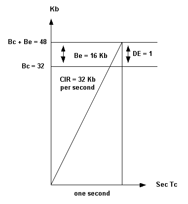
In the example we are using here, the router sends traffic between 48 Kbps and 32 Kbps depending on congestion in the network. Networks may mark frames above Bc with DE but have plenty of spare capacity to transport the frame. The reverse is also possible: they can have limited capacity, yet discard excessive frames immediately. Networks may mark frames above Bc + Be with DE, and possibly transport it, or just drop the frames as suggested by the International Telecommunication Union Telecommunication Standardization Sector specification ITU-T I.370. Traffic shaping throttles the traffic based on backward-explicit congestion notification (BECN) tagged packets from the switch network. If you receive 50 percent BECN, the router decreases the traffic by one eighth of the current transmitted bandwidth for that particular DLCI.
Example
The transmitted speed is 42 Kb. The router decreases the speed to 42 minus 42 divided by 8 (42 - 42/8), making 36.75 Kb. If the congestion decreases after the change, the router reduces the traffic further, dropping to one eighth of current transmitted bandwidth. The traffic is reduced until it reaches the configured CIR value. However, the speed can drop under the CIR when we can still see BECNs. You can specify a bottom limit, such as CIR/2. The network is no longer congested when all frames received from the network no longer have a BECN bit for a given time interval. 200 ms is the default value for this interval.
Generic Traffic Shaping
The Generic traffic shaping feature is a media and encapsulation-independent traffic shaping tool that helps reduce the flow of outbound traffic when there is congestion within the cloud, on the link, or at the receiving endpoint router. We can set it on interfaces or subinterfaces within a router.
Generic traffic shaping is useful in the following situations:
-
When you have a network topology that consists of a high-speed (T1 line speed) connection at the central site and low speed (less than 56 kbps) connections at the branch or telecommuter sites. Because of the speed mismatch, a bottleneck often exists for traffic on the branch or telecommuter sites when the central site sends data at a faster rate that the remote sites can receive. This results in a bottleneck in the last switch before the remote-point router.
-
If you are a service provider that offers sub-rate services, this feature enables you to use the router to partition your T1 or T3 links, for example, into smaller channels. You can configure each subinterface with a token filter bucket that matches the service ordered by a customer.
On your Frame Relay connection, you may want the router to throttle traffic instead of sending it into the network. Throttling the traffic would limit packet loss in the service provider's cloud. The BECN-based throttling capability provided with this feature allows you to have the router dynamically throttle traffic based on receiving BECN tagged packets from the network. This throttling holds packets in the router's buffers to reduce the data flow from the router into the Frame Relay network. The router throttles traffic on a subinterface basis, and the rate is also increased when fewer BECN-tagged packets are received.
Commands for Generic Traffic Shaping
To define rate control, use this command:
traffic-shape rate bit-rate [burst-size [excess-burst-size]] [group access-list]
To throttle BECNs on a Frame Relay interface use this command:
traffic-shape adaptive [bit-rate]
To configure a Frame Relay subinterface to estimate the available bandwidth when it receives BECNs, use the traffic-shape adaptive command.
Note: You must enable traffic shaping on the interface with the traffic-shape rate command before you can use the traffic-shape adaptive command.
The bit rate specified for the traffic-shape rate command is the upper limit, and the bit rate specified for the traffic-shape adaptive command is the lower limit (usually the CIR value) at which traffic is shaped when the interface receives BECNs. The rate actually used is normally between these two rates. You should configure the traffic-shape adaptive command at both ends of the link, as it also configures the device at the flow end to reflect forward explicit congestion notification (FECN) signals as BECNs. This enables the router at the high-speed end to detect and adapt to congestion even when traffic is flowing primarily in one direction.
Example
The following example configures traffic shaping on interface 0.1 with an upper limit (usually Bc + Be) of 128 kbps and a lower limit of 64 kbps. This allows the link to run from 64 to 128 kbps, depending on the congestion level. If the central side has a upper limit of 256 kbps, you should use the lowest upper limit value.
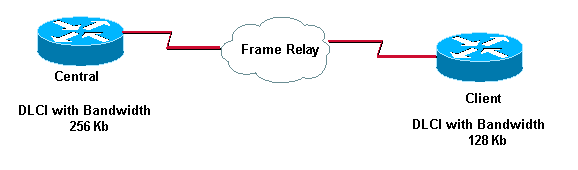
Here's what we have configured on these routers:
Central#
 interface serial 0
  encapsulation-frame-relay
 interface serial 0.1
  traffic-shape rate 128000
  traffic-shape adaptive 64000


Client#
 interface serial 0
  encapsulation-frame-relay
 interface serial 0.1
  traffic-shape rate 128000
  traffic-shape adaptive 64000
Frame Relay Traffic Shaping
With generic traffic shaping you can only specify one peak rate (upper limit) per physical interface and one CIR (lower limit) value per subinterface. With Frame Relay traffic shaping, you start a token bucket filter per Virtual Circuit.
The traffic shaping over Frame Relay feature provides the following capabilities:
-
Rate enforcement on a per-VC basis: You can configure a peak rate to limit outbound traffic to either the CIR or some other defined value such as the excess information rate (EIR).
-
Generalized BECN support on a per-VC basis: The router can monitor BECNs and throttle traffic based on BECN-marked packet feedback from the Frame Relay network.
-
Priority queuing (PQ), custom queuing (CQ) or WFQ support at the VC level. This allows for finer granularity in the prioritisation and queuing of traffic, giving you more control over the traffic flow on an individual VC. The traffic shaping over Frame Relay feature applies to Frame Relay permanent virtual circuits (PVCs) and switched virtual circuits (SVCs).
Example
Interface Serial 0
 no ip address
 encapsulation frame-relay
 frame-relay traffic-shaping
!
interface Serial0.100
 ip address 1.1.1.1 255.255.255.252
 frame-relay interface-dlci 100
 frame-relay class fast
!
interface Serial0.200
 ip address 1.1.1.5 255.255.255.252
 frame-relay interface-dlci 200
 frame-relay class slow
!
map-class frame-relay slow
 frame-relay traffic-rate 64000 128000
!
map-class
 frame-relay fast
 frame-relay traffic-rate 16000 64000
!
In this example the router adds two token-buckets.
-
One runs between 64000 (CIR) and 128000(Bc + Be).
-
The other runs between 16000 (CIR) and 64000 (Bc + Be).
If incoming traffic from Ethernet is larger than the token bucket filter, the traffic is buffered up in the frame-relay traffic queue.
To view a flow chart showing packet flow when you implement Frame Relay traffic shaping, please see Frame Relay Traffic Shaping Flowchart. To view a flow chart specifically using a token bucket filter, please see Frame Relay Traffic Shaping - Token Bucket Flowchart.
Commonly Used Frame Relay Commands
This section describes two Cisco IOS® commands that are especially useful when configuring Frame Relay.
show frame-relay pvc
This command shows the status of the permanent virtual circuit (PVC), packets in and out, dropped packets if there is congestion on the line via forward explicit congestion notification (FECN) and backward explicit congestion notification (BECN), and so on. For a detailed description of the fields used with the show frame-relay pvc command, click here.
If you have the output of a show frame-relay pvc command from your Cisco device, you can use Output Interpreter (registered customers only) to display potential issues and fixes.
Sample output is shown below:
RouterA#show frame-relay pvc
PVC Statistics for interface Serial0 (Frame Relay DTE)
DLCI = 666, DLCI USAGE = UNUSED, PVC STATUS = DELETED, INTERFACE = Serial0
  input pkts 0             output pkts 0            in bytes 0
  out bytes 0              dropped pkts 0           in FECN pkts 0
  in BECN pkts 0           out FECN pkts 0          out BECN pkts 0
  in DE pkts 0             out DE pkts 0
  pvc create time 0:03:18  last time pvc status changed 0:02:27
  Num Pkts Switched 0
DLCI = 980, DLCI USAGE = LOCAL, PVC STATUS = ACTIVE, INTERFACE = Serial0
  input pkts 19            output pkts 87           in bytes 2787
  out bytes 21005          dropped pkts 0           in FECN pkts 0
  in BECN pkts 0           out FECN pkts 0          out BECN pkts 0
  in DE pkts 0             out DE pkts 0
  pvc create time 1:17:47  last time pvc status changed 0:58:27
The DLCI USAGE field contains one of the following entries:
-
SWITCHED - the router or access server is used as a switch.
-
LOCAL - the router or access server is used as data terminal equipment (DTE).
-
UNUSED - the data-link connection identifier (DLCI) is not referenced by user-entered configuration commands on the router.
The PVC can have four possible states. These are shown by the PVC STATUS field as follows:
-
ACTIVE - PVC is up and functioning normally.
-
INACTIVE - PVC is not up end-to-end. This may be because either there is no mapping (or incorrect mapping) for the local DLCI in the frame-relay cloud or the remote end of the PVC is Deleted.
-
DELETED - Either the Local Management Interface (LMI) is not exchanged between the router and the local switch, or the switch does not have DLCI configured on the local switch.
-
STATIC - no keepalive configured on the frame-relay interface of the router.
show frame-relay map
Use this command to determine if frame-relay inverse-arp resolved a remote IP address to a local DLCI. This command is not enabled for point-to-point subinterfaces. It is useful for multipoint interfaces and subinterfaces only. Sample output is shown below:
RouterA#show frame-relay map
Serial0 (up): ip 157.147.3.65 dlci 980(0x3D4,0xF440), dynamic,
         broadcast,, status defined, active
For a detailed description of the fields used with the show frame-relay map command, please see Documentation on frame relay Commands.
If you have the output of a show frame-relay map command from your Cisco device, you can use Output Interpreter (registered customers only) to display potential issues and fixes.
Frame Relay and Bridging
Configuration messages called bridge protocol data units (BPDUs) are used in the spanning-tree protocols supported in Cisco bridges and routers. These flow at regular intervals between bridges and constitute a significant amount of traffic because of their frequent occurrence. There are two types of spanning-tree protocols in transparent bridging. First introduced by the Digital Equipment Corporation (DEC), the algorithm was subsequently revised by the IEEE 802 committee and published in the IEEE 802.1d specification. The DEC Spanning-Tree Protocol issues BPDUs at one-second intervals, while the IEEE issues BPDUs at two-second intervals. Each packet is 41 bytes, which includes a 35-byte configuration BPDU message, a 2-byte Frame Relay header, 2-byte Ethertype, and a 2-byte FCS.
Frame Relay and Memory
Memory consumption for Frame Relay resources occurs in four areas:
-
Each data-link connection identifier (DLCI): 216 bytes
-
Each map statement: 96 bytes (or dynamically built map)
-
Each IDB (hardware interface + encap Frame Relay): 5040 + 8346 = 13,386 bytes
-
Each IDB (software subinterface): 2260 bytes
For example, a Cisco 2501 using two Frame Relay interfaces, each with four subinterfaces, with a total of eight DLCIs, and associated maps needs the following:
-
2-interface hardware IDB x 13,386 = 26,772
-
8-subinterface IDB x 2260 = 18,080 subinterfaces
-
8 DLCIs x 216 = 1728 DLCIs
-
8 map statements x 96 = 768 map statements or dynamics
The total is equal to 47,348 bytes of RAM used.
Note: The values used here are valid for Cisco IOS Release 11.1, 12.0 and 12.1 software.
Troubleshooting Frame Relay
This section contains portions of possible show interface command output you may encounter while troubleshooting. Explanations of the output are provided as well.
"Serial0 is down, line protocol is down"
This output means you have a problem with the cable, channel service unit/data service unit (CSU/DSU), or the serial line. You need to troubleshoot the problem with a loopback test. To do a loopback test, follow the steps below:
-
Set the serial line encapsulation to HDLC and keepalive to 10 seconds. To do so, issue the commands encapsulation hdlc and keepalive 10 under the serial interface.
-
Place the CSU/DSU or modem in local loop mode. If the line protocol comes up when the CSU, DSU or modem is in local loopback mode (indicated by a "line protocol is up (looped)" message), it suggests that the problem is occurring beyond the local CSU/DSU. If the status line does not change states, there is possibly a problem in the router, connecting cable, CSU/DSU or modem. In most cases, the problem is with the CSU/DSU or modem.
-
Ping your own IP address with the CSU/DSU or modem looped. There should not be any misses. An extended ping of 0x0000 is helpful in resolving line problems since a T1 or E1 derives clock from data and requires a transition every 8 bits. B8ZS ensures that. A heavy zero data pattern helps to determine if the transitions are appropriately forced on the trunk. A heavy ones pattern is used to appropriately simulate a high zero load in case there is a pair of data inverters in the path. The alternating pattern (0x5555) represents a "typical" data pattern. If your pings fail or if you get cyclic redundancy check (CRC) errors, a bit error rate tester (BERT) with an appropriate analyzer from the telco is needed.
-
When you are finished testing, make sure you return the encapsulation to Frame Relay.
"Serial0 is up, line protocol is down"
This line in the output means that the router is getting a carrier signal from the CSU/DSU or modem. Check to make sure the Frame Relay provider has activated their port and that your Local Management Interface (LMI) settings match. Generally, the Frame Relay switch ignores the data terminal equipment (DTE) unless it sees the correct LMI (use Cisco's default to "cisco" LMI). Check to make sure the Cisco router is transmitting data. You will most likely need to check the line integrity using loop tests at various locations beginning with the local CSU and working your way out until you get to the provider's Frame Relay switch. See the previous section for how to perform a loopback test.
"Serial0 is up, line protocol is up"
If you did not turn keepalives off, this line of output means that the router is talking with the Frame Relay provider's switch. You should be seeing a successful exchange of two-way traffic on the serial interface with no CRC errors. Keepalives are necessary in Frame Relay because they are the mechanism that the router uses to "learn" which data-link connection identifiers (DLCIs) the provider has provisioned. To watch the exchange, you can safely use debug frame-relay lmi in almost all situations. The debug frame-relay lmi command generates very few messages and can provide answers to questions such as:
-
Is the Cisco Router talking to the local Frame Relay switch?
-
Is the router getting full LMI status messages for the subscribed permanent virtual circuits (PVCs) from the Frame Relay provider?
-
Are the DLCIs correct?
Here's some sample debug frame-relay lmi output from a successful connection:
*Mar  1 01:17:58.763: Serial0(out): StEnq, myseq 92, yourseen 64, DTE up
*Mar  1 01:17:58.763:  datagramstart = 0x20007C, datagramsize = 14
*Mar  1 01:17:58.763:  FR encap = 0x0001030800 75 95 01 01 01 03 02 5C 40
*Mar  1 01:17:58.767:
*Mar  1 01:17:58.815: Serial0(in): Status, myseq 92
*Mar  1 01:17:58.815: RT IE 1, length 1, type 1
*Mar  1 01:17:58.815: KA IE 3, length 2, yourseq 65, myseq 92
*Mar  1 01:18:08.763: Serial0(out): StEnq, myseq 93, yourseen 65, DTE up
*Mar  1 01:18:08.763:  datagramstart = 0x20007C, datagramsize = 14
*Mar  1 01:18:08.763:  FR encap = 0x0001030800 75 95 01 01 01 03 02 5D 41
*Mar  1 01:18:08.767:
*Mar  1 01:18:08.815: Serial0(in): Status, myseq 93
*Mar  1 01:18:08.815: RT IE 1, length 1, type 1
*Mar  1 01:18:08.815: KA IE 3, length 2, yourseq 66, myseq 93
*Mar  1 01:18:18.763: Serial0(out): StEnq, myseq 94, yourseen 66, DTE up
*Mar  1 01:18:18.763:  datagramstart = 0x20007C, datagramsize = 14
*Mar  1 01:18:18.763:  FR encap = 0x0001030800 75 95 01 01 00 03 02 5E 42
*Mar  1 01:18:18.767:
*Mar  1 01:18:18.815: Serial0(in): Status, myseq 94
*Mar  1 01:18:18.815: RT IE 1, length 1, type 0
*Mar  1 01:18:18.819: KA IE 3, length 2, yourseq 67, myseq 94
*Mar  1 01:18:18.819: PVC IE 0x7 , length 0x3 , dlci 980, status 0x2
Notice the status of "DLCI 980" in the output above. The possible values of the status field are explained below:
-
0x0-Added/inactive means that the switch has this DLCI programmed but for some reason (such as the other end of this PVC is down), it is not usable.
-
0x2-Added/active means the Frame Relay switch has the DLCI and everything is operational. You can start sending it traffic with this DLCI in the header.
-
0x3-0x3 is a combination of an active status (0x2) and the RNR (or r-bit) that is set (0x1). This means that the switch - or a particular queue on the switch - for this PVC is backed up, and you stop transmitting in case frames are spilled.
-
0x4-Deleted means that the Frame Relay switch doesn't have this DLCI programmed for the router. But it was programmed at some point in the past. This could also be caused by the DLCIs being reversed on the router, or by the PVC being deleted by the telco in the Frame Relay cloud. Configuring a DLCI (that the switch doesn't have) will show up as a 0x4.
-
0x8-New/inactive
-
0x0a-New/active
Frame Relay Characteristics
This section explains several Frame Relay characteristics of which you should be aware.
IP Split Horizon Checking
IP split horizon checking is disabled by default for Frame Relay encapsulation so routing updates will come in and out the same interface. The routers learn the data-link connection identifiers (DLCIs) they need to use from the Frame Relay switch via Local Management Interface (LMI) updates. The routers then use Inverse ARP for the remote IP address and create a mapping of local DLCIs and their associated remote IP addresses. Additionally, certain protocols such as AppleTalk, transparent bridging, and IPX cannot be supported on partially meshed networks because they require "split horizon," in which a packet received on an interface cannot be transmitted out the same interface, even if the packet is received and transmitted on different virtual circuits. Configuring Frame Relay subinterfaces ensures that a single physical interface is treated as multiple virtual interfaces. This capability allows us to overcome split horizon rules. Packets received on one virtual interface can now be forwarded out another virtual interface, even if they are configured on the same physical interface.
Ping Your Own IP Address on a Multipoint Frame Relay
You are not able to ping your own IP address on a multipoint Frame Relay interface. This is because Frame Relay multipoint (sub)interfaces are non-broadcast, (unlike Ethernet and point-to-point interfaces High-Level Data Link Control [HDLC]), and Frame Relay point-to-point sub-interfaces.
Furthermore, you are not able to ping from one spoke to another spoke in a hub and spoke configuration. This is because there is no mapping for your own IP address (and none were learned via Inverse ARP). But if you configure a static map (using the frame-relay map command) for your own IP address (or one for the remote spoke) to use the local DLCI, you can then ping your devices.
aton#ping  3.1.3.3
   Type escape sequence to abort.
   Sending 5, 100-byte ICMP Echos to 3.1.3.3, timeout is 2 seconds:
   .....
   Success rate is 0 percent (0/5)

   aton#configure terminal
   Enter configuration commands, one per line.  End with CNTL/Z.
   aton(config)#interface serial 1
   aton(config-if)#frame-relay map ip 3.1.3.3 160
   aton(config-if)#

   aton#show frame-relay map
   Serial1 (up): ip 3.1.3.1 dlci 160(0xA0,0x2800), dynamic,
                    broadcast,, status defined, active
   Serial1 (up): ip 3.1.3.2 dlci 160(0xA0,0x2800), static,
                    CISCO, status defined, active
   Serial1 (up): ip 3.1.3.3 dlci 160(0xA0,0x2800), static,
                    CISCO, status defined, active
   aton#ping 3.1.3.3

   Type escape sequence to abort.
   Sending 5, 100-byte ICMP Echos to 3.1.3.3, timeout is 2 seconds:
   !!!!!
   Success rate is 100 percent (5/5), round-trip min/avg/max = 64/68/76 ms
   aton#
   aton#show running-config
   !
   interface Serial1
   ip address 3.1.3.3 255.255.255.0
   no ip directed-broadcast
   encapsulation frame-relay
   frame-relay map ip 3.1.3.2 160
   frame-relay map ip 3.1.3.3 160
   frame-relay interface-dlci 160
   !
The Keyword broadcast
The broadcast keyword provides two functions: it forwards broadcasts when multicasting is not enabled, and it simplifies the configuration of Open Shortest Path First (OSPF) for non-broadcast networks that use Frame Relay.
The broadcast keyword might also be required for some routing protocols -- for example, AppleTalk -- that depend on regular routing table updates, especially when the router at the remote end is waiting for a routing update packet to arrive before adding the route.
By requiring selection of a designated router, OSPF treats a non-broadcast, multi-access network such as Frame Relay in much the same way as it treats a broadcast network. In previous releases, this required manual assignment in the OSPF configuration using the neighbor interface router command. When the frame-relay map command is included in the configuration with the broadcast keyword, and the ip ospf network command (with the broadcast keyword) is configured, there is no need to configure any neighbors manually. OSPF now automatically runs over the Frame Relay network as a broadcast network. (See the ip ospf network interface command for more detail.)
Note: The OSPF broadcast mechanism assumes that IP class D addresses are never used for regular traffic over Frame Relay.
Example
The following example maps the destination IP address 172.16.123.1 to DLCI 100:
interface serial 0
 frame-relay map IP 172.16.123.1 100 broadcast
OSPF uses DLCI 100 to broadcast updates.
Reconfiguring a Subinterface
Once you create a specific type of subinterface, you cannot change it without a reload. For example, you cannot create a multipoint subinterface serial0.2, then change it to point-to-point. To change it, you need to either reload the router or create another subinterface. This is the way the Frame Relay code works in Cisco IOS® software.
DLCI Limitations
DLCI Address Space
Approximately 1000 DLCIs can be configured on a single physical link, given a 10-bit address. Because certain DLCIs are reserved (vendor-implementation-dependent), the maximum is about 1000. The range for a Cisco LMI is 16-1007. The stated range for ANSI/ITU is 16-992. These are the DLCIs carrying user-data.
However, when configuring Frame Relay VCs on subinterfaces, you need to consider a practical limit known as the IDB limit. The total number of interfaces and subinterfaces per system is limited by the number of interface descriptor blocks (IDBs) that your version of Cisco IOS supports. An IDB is a portion of memory that holds information about the interface such as counters, status of the interface, and so on. IOS maintains an IDB for each interface present on a platform and maintains an IDB for each subinterface. Higher speed interfaces require more memory than lower speed interfaces. Each platform contains different amounts of maximum IDBs and these limits may change with each Cisco IOS release.
For more information, see Maximum Number of Interfaces and Subinterfaces for Cisco IOS Software Platforms: IDB Limits.
LMI Status Update
The LMI protocol requires that all permanent virtual circuit (PVC) status reports fit into a single packet and generally limits the number of DLCIs to less than 800, depending on the maximum transmission unit (MTU) size.
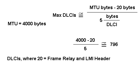
The default MTU on serial interfaces is 1500 bytes, yielding a maximum of 296 DLCIs per interface. You can increase the MTU to support a larger full status update message from the Frame Relay switch. If the full status update message is larger than the interface MTU, the packet is dropped, and the interface giant counter is incremented. When changing the MTU, ensure the same value is configured at the remote router and intervening network devices.
Please note that these numbers vary slightly, depending on the LMI type. The maximum DLCIs per router (not interface) platform guideline, based on extrapolation from empirical data established on a Cisco 7000 router platform, are listed below:
-
Cisco 2500: 1 X T1/E1 link @ 60 DLCIs per interface = 60 total
-
Cisco 4000: 1 X T1/E1 link @ 120 DLCIs per interface = 120 total
-
Cisco 4500: 3 X T1/E1 links @ 120 DLCIs per interface = 360 total
-
Cisco 4700: 4 X T1/E1 links @ 120 DLCIs per interface = 480 total
-
Cisco 7000: 4 X T1/E1/T3/E3 links @ 120 DLCIs per interface = 480 total
-
Cisco 7200: 5 X T1/E1/T3/E3 links @ 120 DLCIs per interface = 600 total
-
Cisco 7500: 6 X T1/E1/T3/E3 links @ 120 DLCIs per interface = 720 total
Note: These numbers are guidelines only, and assume that all traffic is fast-switched.
Other Considerations
A practical DLCI limit also depends on whether the VCs are running a dynamic or static routing protocol. Dynamic routing protocols, and other protocols like IPX SAP that exchange database tables, send hellos and forwarding information messages which must be seen and processed by the CPU. As a general rule, using static routes will allow you to configure a larger number of VCs on a single Frame Relay interface.
IP/IPX/AT Address
If you are using subinterfaces, don't put an IP, IPX or AT address on the main interface. Assign DLCIs to their subinterfaces before you enable the main interface to ensure that frame-relay inverse-arp works properly. In case it does malfunction, follow the steps below:
-
Turn off Inverse Address Resolution Protocol (ARP) for that DLCI by using the no frame-relay inverse-arp ip 16 and the clear frame-relay-inarp commands.
-
Fix your configuration.
-
Turn the frame-relay inverse-arp command on again.
RIP and IGRP
Routing Information Protocol (RIP) updates flow every 30 seconds. Each RIP packet can contain up to 25 route entries, for a total of 536 bytes; 36 bytes of this total are header information, and each route entry is 20 bytes. Therefore, if you advertise 1000 routes over a Frame Relay link configured for 50 DLCIs, the result is 1 MB of routing update data every 30 seconds, or 285 kbps of bandwidth consumed. On a T1 link, this bandwidth represents 18.7 percent of the bandwidth, with each update duration being 5.6 seconds. This amount of overhead is considerable, and it is borderline acceptable, but the committed information rate (CIR) would have to be in the region of the access speed. Obviously, anything less than a T1 would incur too much overhead. For example:
-
1000/25 = 40 packets X 36 = 1440 header bytes
-
1000 X 20 bytes = 20,000 bytes of route entries
-
Total 21,440 bytes X 50 DLCIs = 1072 MB of RIP updates every 30 seconds
-
1,072,000 bytes / 30 sec X 8 bits = 285 kbps
Interior Gateway Routing Protocol (IGRP) updates flow every 90 seconds (this interval is configurable). Each IGRP packet can contain 104 route entries, for a total of 1492 bytes, 38 of which are header information, and each route entry is 14 bytes. If you advertise 1000 routes over a Frame Relay link configured with 50 DLCIs, the request is approximately 720 KB of routing update data every 90 seconds, or 64 kbps of bandwidth consumed. On a T1 link, this bandwidth would represent 4.2 percent of the bandwidth, with each update duration being 3.7 seconds. This overhead is an acceptable amount:
-
1000/104 = 9 packets X 38 = 342 header bytes
-
1000 X 14 = 14,000 bytes of route entries
-
Total = 14,342 bytes X 50 DLCIs = 717 KB of IGRP updates every 90 seconds
-
717,000 bytes / 90 X 8 bits = 63.7 kbps
Routing Table Maintenance Protocol (RTMP) routing updates occur every 10 seconds (this interval is configurable). Each RTMP packet can contain up to 94 extended route entries, for a total of 564 bytes, 23 bytes of header information, and each route entry is 6 bytes. If you advertise 1000 AppleTalk networks over a Frame Relay link configured for 50 DLCIs, the result is approximately 313 KB of RTMP updates every 10 seconds, or 250 kbps of bandwidth consumed. To remain within an acceptable level of overhead 15 percent or less), a T1 rate is required. For example:
-
1000/94 = 11 packets X 23 bytes = 253 header bytes
-
1000 X 6 = 6000 bytes of route entries
-
Total = 6253 X 50 DLCIs = 313 KB of RTMP updates every 10 seconds
-
313,000 / 10 sec X 8 bits = 250 kbps
IPX RIP packet updates occur every 60 seconds (this interval is configurable). Each IPX RIP packet can contain up to 50 route entries for a total of 536 bytes, 38 bytes of header information, and each route entry is 8 bytes. If you advertise 1000 IPX routes over a Frame Relay link configured for 50 DLCIs, the result is 536 KB of IPX updates every 60 seconds, or 58.4 kbps of bandwidth consumed. To remain within an acceptable level of overhead (15 percent or less), a rate of 512 kbps is required. For example:
-
1000/50 = 20 packets X 38 bytes = 760 bytes of header
-
1000 X 8 = 8000 bytes of route entries
-
Total = 8760 X 50 DLCIs = 438,000 bytes of IPX updates every 60 seconds
-
438,000 / 60 sec X 8 bits = 58.4 kbps
IPX service access point (SAP) packet updates occur every 60 seconds (this interval is configurable). Each IPX SAP packet can contain up to seven advertisement entries for a total of 536 bytes, 38 bytes of header information, and each advertisement entry is 64 bytes. If you broadcast 1000 IPX advertisements over a Frame Relay link configured for 50 DLCIs, you would end up with 536 KB of IPX updates every 60 seconds, or 58.4 kbps of bandwidth consumed. To remain within an acceptable level of overhead (15 percent or less), a rate of greater than 2 Mbps is required. Obviously, SAP filtering is required in this scenario. Compared to all other protocols mentioned in this section, IPX SAP updates require the most bandwidth:
-
1000/7 = 143 packets X 38 bytes = 5434 bytes of header
-
1000 X 64 = 64,000 bytes of route entries
-
Total = 69,434 X 50 DLCIs = 3,471,700 bytes of IPX service advertisements every 60 seconds
-
3,471,700 / 60 sec X 8 bits = 462 kbps
Keepalive
In some cases, the keepalive on the Cisco device needs to be set slightly shorter (about 8 seconds) than the keepalive on the switch. You'll see the need for this if the interface keeps coming up and down.
Serial Interfaces
Serial interfaces, which are by default multipoint, are non-broadcast media, while point-to-point subinterfaces are broadcast. If you are using static routes, you can point to either the next hop or the serial subinterface. For multipoint, you need to point to the next hop. This concept is very important when doing OSPF over Frame Relay. The router needs to know that this is a broadcast interface for OSPF to work.
OSPF and Multipoint
OSPF and multipoint can be very troublesome. OSPF needs a Designated Router (DR). If you start losing PVCs, some routers may lose connectivity and try to become a DR even though other routers still see the old DR. This causes the OSPF process to malfunction.
Overhead associated with OSPF is not as obvious and predictable as that with traditional distance vector routing protocols. The unpredictability comes from whether or not the OSPF network links are stable. If all adjacencies to a Frame Relay router are stable, only neighbor hello packets (keepalives) will flow, which is comparatively much less overhead than that incurred with a distance vector protocol (such as RIP and IGRP). If, however, routes (adjacencies) are unstable, link-state flooding will occur, and bandwidth can quickly be consumed. OSPF also is very processor-intensive when running the Dijkstra algorithm, which is used for computing routes.
In earlier releases of Cisco IOS software, special care had to be taken when configuring OSPF over multiaccess nonbroadcast medias such as Frame Relay, X.25, and ATM. The OSPF protocol considers these media like any other broadcast media such as Ethernet. Nonbroadcast multiaccess (NBMA) clouds are typically built in a hub and spoke topology. PVCs or switched virtual circuits (SVCs) are laid out in a partial mesh and the physical topology does not provide the multiaccess that OSPF believes is there. For the case of point-to-point serial interfaces, OSPF always forms an adjacency between the neighbors. OSPF adjacencies exchange database information. In order to minimize the amount of information exchanged on a particular segment, OSPF elects one router to be a DR, and one router to be a backup designated router (BDR) on each multiaccess segment. The BDR is elected as a backup mechanism in case the DR goes down.
The idea behind this setup is that routers have a central point of contact for information exchange. The selection of the DR became an issue because the DR and BDR needed to have full physical connectivity with all routers that exist on the cloud. Also, because of the lack of broadcast capabilities, the DR and BDR needed to have a static list of all other routers attached to the cloud. This setup is achieved using the neighbor command:
neighbor ip-address [priority number] [poll-interval seconds]
In later releases of Cisco IOS software, different methods can be used to avoid the complications of configuring static neighbors and having specific routers becoming DRs or BDRs on the nonbroadcast cloud. Which method to use is influenced by whether the network is new or an existing design that needs modification.
A subinterface is a logical way of defining an interface. The same physical interface can be split into multiple logical interfaces, with each subinterface being defined as point-to-point. This scenario was originally created in order to better handle issues caused by split horizon over NBMA and vector based routing protocols.
A point-to-point subinterface has the properties of any physical point-to-point interface. As far as OSPF is concerned, an adjacency is always formed over a point-to-point subinterface with no DR or BDR election. OSPF considers the cloud a set of point-to-point links rather than one multiaccess network. The only drawback for the point-to-point is that each segment belongs to a different subnet. This scenario might not be acceptable because some administrators have already assigned one IP subnet for the whole cloud. Another workaround is to use IP unnumbered interfaces on the cloud. This scenario also might be a problem for some administrators who manage the WAN based on IP addresses of the serial lines.
Sources
-
International Telegraph and Telephone Consultative Committee, "ISDN Data Link Layer Specification for Frame Mode Bearer Services", CCITT Recommendation Q.922, 19 April 1991.
-
American National Standard For Telecommunications - Integrated Services Digital Network - Core Aspects of Frame Protocol for Use with Frame Relay Bearer Service, ANSI T1.618-1991, 18 June 1991.
-
Information technology - Telecommunications and Information Exchange between systems - Protocol Identification in the Network Layer, ISO/IEC TR 9577: 1990 (E) 1990-10-15.
-
International Standard, Information Processing Systems - Local Area Networks - Logical Link Control, ISO 8802-2: 1989 (E), IEEE Std 802.2-1989, 1989-12-31.
-
Internetworking Technology Overview, October 1994, Cisco Systems
-
Finlayson, R., Mann, R., Mogul, J., and M. Theimer, "Reverse Address Resolution Protocol", STD 38, RFC 903, Stanford University, June 1984.
-
Postel, J. and Reynolds, J., "Standard for the Transmission of IP Datagrams over IEEE 802 Networks", RFC 1042, USC/Information Sciences Institute, February 1988.
-
Frame Relay Forum (FRF) 1.1-User-Network Interface (UNI)
-
FRF 2.1-Frame Relay Network-to-Network Interface (NNI)
-
FRF 3.1-Multiprotocol encapsulation
-
FRF 4-SVCs
-
FRF 6-Frame Relay service customer network management (MIB)
-
Gang of four LMI
-
Q.922 Annex A
-
ANSI T1.617 Annex D
-
ANSI T1.618, T1.606
-
ITU-T Q.933, Q.922
-
Configuration Notes for the Enhanced Implementation of Enhanced IGRP
Related Information
- More Information on Frame Relay Commands
- More Information on Configuring Frame Relay
- More Information on Dial-Backup Commands
- More Information on ISDN Debug Commands
- More Information on PPP Debug Commands
- More Information on ISDN Switch Types, Codes and Values
- Technical Support & Documentation - Cisco Systems
 Feedback
Contact Cisco
- Open a Support Case

- (Requires a Cisco Service Contract)