Configuring Basic MPLS Using IS-IS
Available Languages
Contents
Introduction
This sample configuration shows how to set up a Multiprotocol Label Switching (MPLS) network for further tasks such as Virtual Private Network (VPN) or traffic engineering (see more Sample Configurations on the MPLS Support Page).
Prerequisites
Requirements
Before attempting this configuration, please ensure that you meet the following prerequisites:
-
In order to implement MPLS, you need a Cisco 2600 router or later.
-
Choose the required Cisco IOS with MPLS using the Software Advisor (registered customers only) .
-
Check for the additional RAM and Flash memory required to run MPLS in the routers. WAN interface cards (WICs), WIC-1T and WIC-2T, can be used.
Components Used
The information in this document is based on the software and hardware versions below.
-
Cisco 3640, Cisco 3660, Cisco 4500, and Cisco 2610 Routers
-
Cisco IOS® Software Release 12.2(6h) is running on all the routers
The information presented in this document was created from devices in a specific lab environment. All of the devices used in this document started with a cleared (default) configuration. If you are working in a live network, ensure that you understand the potential impact of any command before using it.
Background Theory
An MPLS network is commonly a backbone network comprised of MPLS-enabled routers called Label Switch Routers (LSR). Generally, the network consists of a core LSR with an edge LSR responsible for applying labels to packets.
The set-up mechanism of an MPLS network is the following.
-
Routing tables of the different LSRs are computed using an Interior Gateway Protocol (IGP). A link-state protocol such as Open Shortest Path First (OSPF) or Intermediate System-to-Intermediate System (IS-IS) is required if you're going to deploy MPLS Traffic Engineering.
-
A label distribution protocol (LDP) advertises the bindings between routes and labels. These bindings are checked against the routing table. If the route (prefix/mask and next hop) learned via the LDP matches the route learned via IGP in the routing table, an entry is created in the label forwarding information bases (LFIB) on the LSR.
The LSR uses the following forwarding mechanism.
-
Once an edge LSR receives an unlabeled packet, the Cisco express forwarding table is checked and a label is imposed on the packet if needed. This LSR is called the ingress LSR.
-
Upon the arrival of a labelled packet at the incoming interface of a core LSR, the LFIB provides the outgoing interface and the new label that will be associated with the outgoing packet.
-
The router before the last LSR (the penultimate hop) pops the label and transmits the packet without the label. The last hop is called the egress LSR.
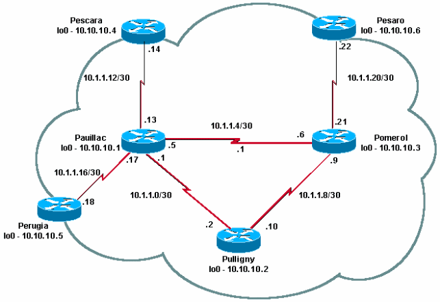
The following diagram illustrates this network setup.
Conventions
For more information on document conventions, see the Cisco Technical Tips Conventions.
Configure
In this section, you are presented with the information to configure the features described in this document.
Note: To find additional information on the commands used in this document, use the Command Lookup Tool (registered customers only) .
Network Diagram
This document uses this network setup:
Configurations
This document uses these configurations:
Quick Configuration Guide
Complete these steps to configure MPLS:
-
Set up your network as usual (MPLS needs a standard IP connection in order to establish forwarding bases).
-
Ensure that the routing protocol (OSPF or IS-IS) is working correctly. These commands are shown in italics in the configurations in this section.
-
Use the ip cef command (for better performances, use the ip cef distributed command when available) in the general configuration mode (shown in bold in the configurations in this section) to enable.
-
Use the mpls ip command (or the tag-switching ip command on older Cisco IOS software releases) in the general configuration mode and in each interface (shown in bold in the configurations in this section) to enable.
Note: The LSRs must have (up) Loopback interfaces with an address mask of 32 bits.
| Pomerol |
|---|
Current configuration: ! version 12.2 ! hostname Pomerol ! ip cef !--- Enables Cisco Express Forwarding globally. ! interface Loopback0 ip address 10.10.10.3 255.255.255.255 ip router isis !--- Assigns an IP address to interface loopback0 !--- and enables IS-IS for IP on the interface. ! interface Serial0/0 encapsulation frame-relay ! interface Serial0/0.1 point-to-point ip address 10.1.1.6 255.255.255.252 ip router isis tag-switching ip !--- Enables dynamic Label Switching of !--- IPv4 packets on an interface. frame-relay interface-dlci 301 ! interface Serial0/0.2 point-to-point ip address 10.1.1.9 255.255.255.252 ip router isis tag-switching ip frame-relay interface-dlci 303 ! interface Serial0/0.3 point-to-point ip address 10.1.1.21 255.255.255.252 ip router isis tag-switching ip frame-relay interface-dlci 306 ! router isis net 49.0001.0000.0000.0003.00 is-type level-1 ! ip classless ! end |
| Pulligny |
|---|
Current configuration: ! version 12.1 ! hostname Pulligny ! ip cef ! interface Loopback0 ip address 10.10.10.2 255.255.255.255 ! interface Serial0/1 no ip address encapsulation frame-relay ! interface Serial0/0.1 point-to-point ip address 10.1.1.2 255.255.255.252 ip router isis tag-switching ip frame-relay interface-dlci 201 ! interface Serial0/0.2 point-to-point ip address 10.1.1.10 255.255.255.252 ip router isis tag-switching ip frame-relay interface-dlci 203 ! router isis redistribute static ip passive-interface Loopback0 net 49.0001.0000.0000.0002.00 is-type level-1 !--- Enables the IS-IS process on the router, !--- makes loopback interface passive !--- (does not send IS-IS packets on interface), !--- and assigns area and system ID to router. ! ip classless ! end |
| Pauillac |
|---|
Current configuration : 2366 bytes ! version 12.1 ! hostname pauillac ! ip cef ! interface Loopback0 ip address 10.10.10.1 255.255.255.255 ip router isis ! interface Serial0/0 no ip address encapsulation frame-relay ! interface Serial0/0.1 point-to-point ip address 10.1.1.1 255.255.255.252 ip router isis tag-switching ip frame-relay interface-dlci 102 ! interface Serial0/0.2 point-to-point ip address 10.1.1.5 255.255.255.252 ip access-group 150 out ip router isis tag-switching ip frame-relay interface-dlci 103 ! interface Serial0/0.3 point-to-point bandwidth 512 ip address 10.1.1.13 255.255.255.252 ip router isis tag-switching ip frame-relay interface-dlci 104 ! interface Serial0/0.4 point-to-point ip address 10.1.1.17 255.255.255.252 ip router isis tag-switching ip frame-relay interface-dlci 105 ! ! router isis net 49.0001.0000.0000.0001.00 is-type level-1 ! ip classless ! end |
Verify
This section provides information you can use to confirm your configuration is working properly.
Certain show commands are supported by the Output Interpreter Tool (registered customers only) , which allows you to view an analysis of show command output.
-
show tag-switching tdp neighbor
-
show tag-switching tdp bindings
-
show tag-switching forwarding-table
-
show tag-switching forwarding-table a.b.c.d detail
-
traceroute a.b.c.d
An exhaustive list of commands is included in the MPLS Command Reference. Other sample show commands are described in Configuring Basic MPLS Using OSPF.
Sample Output
This output focuses on the LDP. The LDP currently implemented in IOS is TDP (Tag Distribution Protocol), which contains some Cisco-proprietary extensions, but it be used with LDP, the IETF official protocol for label distribution. TDP will be replaced by LDP in the future.
You can use the show tag-switching tdp * command in order to verify the state of TDP. You can see neighbors with the show tag-switching tdp neighbor command.
Pulligny# show tag-switching tdp discovery
Local TDP Identifier:
	10.10.10.2:0
TDP Discovery Sources:
  Interfaces:
 Serial0/0.1: xmit/recv
   TDP Id: 10.10.10.1:0
 Serial0/0.2: xmit/recv
   TDP Id: 10.10.10.3:0

!--- Ensure you are able to ping this IP address !--- If not, check whether a route exists in the routing table
Pulligny# show tag-switching tdp neighbor
Peer TDP Ident: 10.10.10.1:0; Local TDP Ident 10.10.10.2:0
        TCP connection: 10.10.10.1.711 - 10.10.10.2.11001
        State: Oper; PIEs sent/rcvd: 27907/27925; ; Downstream
        Up time: 2w2d
        TDP discovery sources:
          Serial0/0.1
        Addresses bound to peer TDP Ident:
          10.1.1.1        10.1.1.13       10.1.1.17       10.10.10.1
          10.1.1.5        10.200.28.89
Peer TDP Ident: 10.10.10.3:0; Local TDP Ident 10.10.10.2:0
        TCP connection: 10.10.10.3.11001 - 10.10.10.2.711
        State: Oper; PIEs sent/rcvd: 22893/22874; ; Downstream
        Up time: 1w6d
        TDP discovery sources:
          Serial0/0.2
        Addresses bound to peer TDP Ident:
          10.200.28.91    10.1.1.6        10.1.1.9        10.1.1.21
          10.10.10.3
You can use the show tag-switching tdp bindings command in order to view the established bindings between labels and routes.
Pulligny# show tag-switching tdp bindings
(...)
  tib entry: 10.10.10.4/32, rev 22
        local binding:  tag: 21
        remote binding: tsr: 10.10.10.1:0, tag: 22
        remote binding: tsr: 10.10.10.3:0, tag: 25
  tib entry: 10.10.10.6/32, rev 51
        local binding:  tag: 23
        remote binding: tsr: 10.10.10.3:0, tag: 18
        remote binding: tsr: 10.10.10.1:0, tag: 20
(...)
You can use the show tag-switching forwarding-table command in order to see which bindings are used to build the LFIB.
Pulligny# show tag-switching forwarding-table
Local  Outgoing    Prefix            Bytes tag  Outgoing   Next Hop
tag    tag or VC   or Tunnel Id      switched   interface
16     Pop tag     10.1.1.4/30       0          Se0/0.2    point2point
       Pop tag     10.1.1.4/30       0          Se0/0.1    point2point
17     Pop tag     10.1.1.20/30      0          Se0/0.2    point2point
18     Pop tag     10.10.10.3/32     0          Se0/0.2    point2point
19     Pop tag     10.10.10.1/32     0          Se0/0.1    point2point
20     Pop tag     10.1.1.12/30      0          Se0/0.1    point2point
21     Pop tag     10.1.1.16/30      0          Se0/0.1    point2point
22     20          10.10.10.5/32     0          Se0/0.1    point2point
23     22          10.10.10.6/32     0          Se0/0.2    point2point
24     22          10.10.10.4/32     0          Se0/0.1    point2point
You can use the show tag-switching forwarding-table 10.10.10.4 detail command to view the details of a given destination.
Pulligny# show tag-switching forwarding-table 10.10.10.4 detail
Local  Outgoing    Prefix            Bytes tag  Outgoing   Next Hop
tag    tag or VC   or Tunnel Id      switched   interface
21     22          10.10.10.4/32     12103      Se0/0.1    point2point
        MAC/Encaps=4/8, MTU=1500, Tag Stack{22}
        30918847 00016000
    Per-packet load-sharing
You can also use the traceroute command, if the network does IP TTL propagation, to view the hops. Refer to Multiprotocol Label Switching on Cisco Routers for more information on the mpls ip ttl propagate command.
Pesaro# traceroute 10.10.10.4

Type escape sequence to abort.
Tracing the route to 10.10.10.4

  1 10.1.1.21 [MPLS: Label 25 Exp 0] 296 msec 256 msec 244 msec
  2 10.1.1.5 [MPLS: Label 22 Exp 0] 212 msec 392 msec 352 msec
  3 10.1.1.14 436 msec *  268 msec
Note: Exp 0 appears in the output if the experimental field is used for Quality of Service (QoS).
Troubleshoot
There is currently no specific troubleshooting information available for this configuration.
Related Information
Revision History
| Revision | Publish Date | Comments |
|---|---|---|
1.0 |
16-Nov-2007
|
Initial Release |
 Feedback