The "%TUN-5-RECURDOWN" Error Message and Flapping EIGRP/OSPF/BGP Neighbors Over a GRE Tunnel
Available Languages
Contents
Introduction
The %TUN-5-RECURDOWN: Tunnel0 temporarily disabled due to recursive routing error message means that the generic routing encapsulation (GRE) tunnel router has discovered a recursive routing problem. This condition is usually due to one of these causes:
-
A misconfiguration that causes the router to try to route to the tunnel destination address using the tunnel interface itself (recursive routing)
-
A temporary instability caused by route flapping elsewhere in the network
Tunnel interface status depends on the IP reachability to the tunnel destination. When the router detects a recursive routing failure for the tunnel destination, it shuts the tunnel interface down for a few minutes so that the situation causing the problem can resolve itself as routing protocols converge. If the problem is caused by misconfiguration, the link can oscillate indefinitely.
Another symptom of this problem is continuously flapping Enhanced Interior Gateway Routing Protocol (EIGRP), Open Shortest Path First (OSPF), or Border Gateway Protocol (BGP) neighbors, when the neighbors are over a GRE tunnel.
This document shows an example of troubleshooting an oscillating tunnel interface that is running EIGRP.
Prerequisites
Requirements
There are no specific requirements for this document.
Components Used
This document is not restricted to specific software or hardware versions.
The information in this document was created from the devices in a specific lab environment. All of the devices used in this document started with a cleared (default) configuration. If your network is live, make sure that you understand the potential impact of any command.
Conventions
Refer to Cisco Technical Tips Conventions for more information on document conventions.
Network Diagram
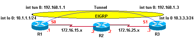
Router 1 (R1) and Router 3 (R3) are connected to Router 2 (R2). The network connectivity is such that R1 can reach R3’s loopback interface through R2 and vice versa. EIGRP is running over the tunnel interface on R1 and R3. R2 is not part of the EIGRP domain.
Configurations
| R1 |
|---|
hostname R1 ! interface Loopback0 ip address 10.1.1.1 255.255.255.0 ! interface Tunnel0 ip address 192.168.1.1 255.255.255.0 tunnel source Loopback0 tunnel destination 10.3.3.3 ! interface Serial0 ip address 172.16.15.1 255.255.255.0 encapsulation ppp ! router eigrp 1 network 10.1.1.0 0.0.0.255 network 192.168.1.0 no auto-summary ! ip route 0.0.0.0 0.0.0.0 172.16.15.2 |
| R3 |
|---|
hostname R3 ! interface Loopback0 ip address 10.3.3.3 255.255.255.0 ! interface Tunnel0 ip address 192.168.1.3 255.255.255.0 tunnel source Loopback0 tunnel destination 10.1.1.1 ! interface Serial1 ip address 172.16.25.3 255.255.255.0 ! router eigrp 1 network 10.3.3.0 0.0.0.255 network 192.168.1.0 no auto-summary ! ip route 0.0.0.0 0.0.0.0 172.16.25.2 |
Observation
Observe these error messages on R1 and R3. The state of the tunnel interface is continuously oscillating between up and down.
01:11:39: %LINEPROTO-5-UPDOWN:
          Line protocol on Interface Tunnel0, changed state to up
01:11:48: %TUN-5-RECURDOWN:
          Tunnel0 temporarily disabled due to recursive routing
01:11:49: %LINEPROTO-5-UPDOWN:
          Line protocol on Interface Tunnel0, changed state to down
01:12:49: %LINEPROTO-5-UPDOWN:
          Line protocol on Interface Tunnel0, changed state to up
01:12:58: %TUN-5-RECURDOWN:
          Tunnel0 temporarily disabled due to recursive routing
01:12:59: %LINEPROTO-5-UPDOWN:
          Line protocol on Interface Tunnel0, changed state to down
Note: Each time-stamped line of example previous output appears on one line in actual output.
Troubleshooting
This is the route to tunnel destination 10.3.3.3 on R1 before the tunnel interface goes up:
R1# show ip route
Codes: C - connected, S - static, I - IGRP, R - RIP, M - mobile, B - BGP
       D - EIGRP, EX - EIGRP external, O - OSPF, IA - OSPF inter area
       N1 - OSPF NSSA external type 1, N2 - OSPF NSSA external type 2
       E1 - OSPF external type 1, E2 - OSPF external type 2, E - EGP
       i - IS-IS, L1 - IS-IS level-1, L2 - IS-IS level-2, ia - IS-IS inter area
       * - candidate default, U - per-user static route, o - ODR
       P - periodic downloaded static route

Gateway of last resort is 172.16.15.2 to network 0.0.0.0

     172.16.0.0/16 is variably subnetted, 2 subnets, 2 masks
C       172.16.15.2/32 is directly connected, Serial0
C       172.16.15.0/24 is directly connected, Serial0
     10.0.0.0/24 is subnetted, 1 subnets
C       10.1.1.0 is directly connected, Loopback0
S*   0.0.0.0/0 [1/0] via 172.16.15.2
The tunnel destination 10.3.3.3 takes the default route out through 172.16.15.2 (Serial 0).
Now, observe the routing table after the tunnel interface goes up, shown here:
R1# show ip route
Codes: C - connected, S - static, I - IGRP, R - RIP, M - mobile, B - BGP
       D - EIGRP, EX - EIGRP external, O - OSPF, IA - OSPF inter area
       N1 - OSPF NSSA external type 1, N2 - OSPF NSSA external type 2
       E1 - OSPF external type 1, E2 - OSPF external type 2, E - EGP
       i - IS-IS, L1 - IS-IS level-1, L2 - IS-IS level-2, ia - IS-IS inter area
       * - candidate default, U - per-user static route, o - ODR
       P - periodic downloaded static route

Gateway of last resort is 172.16.15.2 to network 0.0.0.0

     172.16.0.0/16 is variably subnetted, 3 subnets, 2 masks
D       172.16.25.0/24 [90/297756416] via 192.168.1.3, 00:00:00, Tunnel0
C       172.16.15.2/32 is directly connected, Serial0
C       172.16.15.0/24 is directly connected, Serial0
     10.0.0.0/24 is subnetted, 2 subnets
D       10.3.3.0 [90/297372416] via 192.168.1.3, 00:00:00, Tunnel0
C       10.1.1.0 is directly connected, Loopback0
C    192.168.1.0/24 is directly connected, Tunnel0
S*   0.0.0.0/0 [1/0] via 172.16.15.2
The route to tunnel destination 10.3.3.3 is learned through EIGRP, and its next hop is interface Tunnel 0.
In this situation, the best path to the tunnel destination is through the tunnel interface; however, this occurs:
-
The packet is queued in the output queue of the tunnel interface.
-
The tunnel interface adds a GRE header to the packet and queues the packet to the transport protocol destined to the destination address of the tunnel interface.
-
IP looks up the route to the destination address and learns that it is through the tunnel interface, which returns the packet to Step 1 above; hence, there is a recursive routing loop.
Solution
Configure static routes for the tunnel destination on both R1 and R3.
R1(config)# ip route 10.3.3.3 255.255.255.255  serial 0
R3(config)# ip route 10.1.1.1 255.255.255.255 serial 1
Now, observe the IP route on R1, shown below.
R1# show ip route
Codes: C - connected, S - static, I - IGRP, R - RIP, M - mobile, B - BGP
       D - EIGRP, EX - EIGRP external, O - OSPF, IA - OSPF inter area
       N1 - OSPF NSSA external type 1, N2 - OSPF NSSA external type 2
       E1 - OSPF external type 1, E2 - OSPF external type 2, E - EGP
       i - IS-IS, L1 - IS-IS level-1, L2 - IS-IS level-2, ia - IS-IS inter area
       * - candidate default, U - per-user static route, o - ODR
       P - periodic downloaded static route

Gateway of last resort is 172.16.15.2 to network 0.0.0.0

     172.16.0.0/16 is variably subnetted, 3 subnets, 2 masks
D       172.16.25.0/24 [90/297756416] via 192.168.1.3, 00:01:08, Tunnel0
C       172.16.15.2/32 is directly connected, Serial0
C       172.16.15.0/24 is directly connected, Serial0
     10.0.0.0/8 is variably subnetted, 3 subnets, 2 masks
S       10.3.3.3/32 is directly connected, Serial0
D       10.3.3.0/24 [90/297372416] via 192.168.1.3, 00:01:08, Tunnel0
C       10.1.1.0/24 is directly connected, Loopback0
C    192.168.1.0/24 is directly connected, Tunnel0
S*   0.0.0.0/0 [1/0] via 172.16.15.2
A more specific static route (10.3.3.3/32) is preferable to the less specific EIGRP learned route (10.3.3.0/24) for the tunnel destination. This more specific static route avoids the recursive routing loop, the flapping tunnel interface, and, consequently, the flapping of EIGRP neighbors.
R1# show interfaces tunnel 0
Tunnel0 is up, line protocol is up
  Hardware is Tunnel
  Internet address is 192.168.1.1/24
  MTU 1514 bytes, BW 9 Kbit, DLY 500000 usec,
     reliability 255/255, txload 1/255, rxload 1/255
  Encapsulation TUNNEL, loopback not set
  Keepalive set (10 sec)
  Tunnel source 10.1.1.1 (Loopback0), destination 10.3.3.3
%Warning: Feature not supported in hardware. Tunnel packets will be software switched
The message is seen when the same loopback or physical address is used as the source for two different tunnels. Due to this, every packet goes to the processor, instead of being hardware switched.
This issue can be solved if you use secondary addresses on a loopback interface or if you use multiple loopback interfaces for the tunnel source addresses.
OSPF hello packet is sent by a router over GRE tunnel but it does not arrives on the other end of the tunnel.
In an OSPF enabled network, the router R1 sends the OSPF hello packet over the GRE tunnel but it is not received by the router R3. Use the debug ip ospf hello command in order to debug the hello events.
R1#debug ip ospf hello
May 31 13:58:29.675 EDT: OSPF: Send hello to 224.0.0.5 area 0.0.0.12 on Tunnel0 from 192.168.1.1
May 31 13:58:39.675 EDT: OSPF: Send hello to 224.0.0.5 area 0.0.0.12 on Tunnel0 from 192.168.1.1
May 31 13:58:49.675 EDT: OSPF: Send hello to 224.0.0.5 area 0.0.0.12 on Tunnel0 from 192.168.1.1


R3#debug ip ospf hello
May 31 15:02:07 ADT: OSPF: Send hello to 224.0.0.5 area 0.0.0.12 on Tunnel0 from 192.168.1.3
May 31 15:02:09 ADT: OSPF: Rcv hello from 172.16.15.1 area 0.0.0.12 from Tunnel0 192.168.1.1
May 31 15:02:09 ADT: OSPF: Send immediate hello to nbr 172.16.15.3, src address 192.168.1.3, on Tunnel0
May 31 15:02:09 ADT: OSPF: Send hello to 224.0.0.5 area 0.0.0.12 on Tunnel0 from 192.168.1.3

!--- The previous output shows that the hello packets !--- re sent by R1 but not received by R3.
Solution
Configure the tunnel key command on the interface tunnel 10 on both the routers. This command enables multicast on GRE.
Related Information
Revision History
| Revision | Publish Date | Comments |
|---|---|---|
1.0 |
11-Sep-2018
|
Initial Release |
 Feedback