Voice Design and Implementation Guide
Available Languages
Contents
Introduction
This document details the design and implementation principles for Voice technologies.
Prerequisites
Requirements
There are no specific requirements for this document.
Components Used
This document is not restricted to specific software and hardware versions.
Conventions
For more information on document conventions, refer to the Cisco Technical Tips Conventions.
Design a Dial Plan for Voice-Capable Router Networks
Although most people are not acquainted with dial plans by name, they have become accustomed to using them. The North American telephone network is designed around a 10-digit dial plan that consists of area codes and 7-digit telephone numbers. For telephone numbers located within an area code, a 7-digit dial plan is used for the public switched telephone network (PSTN). Features within a telephone switching machine (such as Centrex) allow for the use of a custom 5-digit dial plan for specific customers who subscribe to that service. Private branch exchanges (PBXs) also allow for variable length dial plans that contain three to eleven digits. Dial plans contain specific dialing patterns for a user who wants to reach a particular telephone number. Access codes, area codes, specialized codes, and combinations of the numbers of digits dialed are all a part of any particular dial plan.
Dial plans require knowledge of the customer's network topology, current telephone number dialing patterns, proposed router/gateway locations, and traffic routing requirements. If the dial plans are for a private internal voice network that is not accessed by the outside voice network, the telephone numbers can be any number of digits.
The dial plan design process begins with the collection of specific information about the equipment to be installed and the network to which it is to be connected. Complete a Site Preparation Checklist for each unit in the network. This information, coupled with a network diagram, is the basis for the number plan design and corresponding configurations.
Dial plans are associated with the telephone networks to which they are connected. They are usually based on numbering plans and the traffic in terms of the number of voice calls the network is expected to carry.
For more information about Cisco IOS® dial peers, refer to these documents:
-
Voice - Understanding Dial Peers and Call Legs on Cisco IOS Platforms
-
Understanding Inbound and Outbound Dial Peers on Cisco IOS Platforms
-
Understanding How Inbound and Outbound Dial Peers are Matched on Cisco IOS Platforms
North American Numbering Plan
The North American Numbering Plan (NANP) consists of a 10-digit dial plan. This is divided into two basic parts. The first three digits refer to the Numbering Plan Area (NPA), commonly referred to as the "area code." The remaining seven digits are also divided into two parts. The first three numbers represent the central office (CO) code. The remaining four digits represent a station number.
The NPA, or area codes, are provided in this format:
-
N 0/1/2/3
-
N is a value of two through nine.
-
The second digit is a value of zero through eight.
-
The third digit is a value of zero through nine.
-
The second digit, when set to a value of zero through eight, is used to immediately distinguish between 10- and 7-digit numbers. When the second and third digits are both "one", this indicates a special action.
-
211 = Reserved.
-
311 = Reserved.
-
411 = Directory assistance.
-
511 = Reserved.
-
611 = Repair service.
-
711 = Reserved.
-
811 = Business office.
-
911 = Emergency.
Additionally, the NPA codes also support Service Access Codes (SAC). These codes support 700, 800, and 900 services.
Central Office Codes
The CO codes are assigned within an NPA by the serving Bell Operating Company (BOC). These CO codes are reserved for special use:
-
555 = Toll directory assistance
-
844 = Time Service
-
936 = Weather Service
-
950 = Access to inter-exchange carriers (IXCs) under Feature Group "B" access
-
958 = Plant test
-
959 = Plant test
-
976 = Information Delivery Service
Some "NN0" (last digit "0") codes are also reserved.
Access Codes
Normally a "1" is transmitted as the first digit to indicate a long distance toll call. However, some special 2-digit prefix codes are also used:
-
00 = Inter-exchange Operator assistance
-
01 = Used for International Direct Distance Dialing (IDDD).
-
10 = Used as part of the 10XXX sequence. "XXX" specifies the equal access IXC.
-
11 = Access code for custom calling services. This is the same function that is achieved by the dual tone multifrequency (DTMF) "*" key.
The 10XXX sequence signifies a carrier access code (CAC). The "XXX" is a 3-digit number assigned to the carrier through BellCore, such as:
-
031 = ALC/Allnet
-
222 = MCI
-
223 = Cable and wireless
-
234 = ACC Long Distance
-
288 = AT&T
-
333 = Sprint
-
432 = Litel (LCI International)
-
464 555 = WilTel
-
488 = Metromedia Communication
New 1010XXX and 1020XXX access codes are added. Check your local telephone directory for an up-to-date list.
CCITT International Numbering Plan
In the early 1960s, the Consultative Committee for International Telegraph and Telephone (CCITT) developed a numbering plan that divided the world into nine zones:
-
1 = North America
-
2 = Africa
-
3 = Europe
-
4 = Europe.
-
5 = Central and South America
-
6 = South Pacific
-
7 = USSR
-
8 = Far East
-
9 = Middle East and Southeast Asia
Additionally, each country is assigned a country code (CC) . This is either one, two, or three digits long. It begins with a zone digit.
The method recommended by the International Telecommunication Union Telecommunication Standardization Sector (ITU-T) (formerly the CCITT) is set forth in Recommendation E.123. International format numbers use the plus sign (+), followed by the country code, then the Subscriber Trunk Dialing (STD) code, if any (without common STD/area code prefix digits or long distance access digits), then the local number. These numbers (given as examples only) describe some of the formats used:
| City | Domestic Number | International Format |
|---|---|---|
| Toronto, Canada | (416) 872-2372 | + 1 416 872 2372 |
| Paris, France | 01 33 33 33 33 | + 33 1 33 33 33 33 |
| Birmingham, UK | (0121) 123 4567 | + 44 121 123 4567 |
| Colon, Panama | 441-2345 | + 507 441 2345 |
| Tokyo, Japan | (03) 4567 8901 | + 81 3 4567 8901 |
| Hong Kong | 2345 6789 | + 852 2345 6789 |
In most cases, the initial 0 of an STD code does not form part of the international format number. Some countries use a common prefix of 9 (such as Colombia, and formerly Finland). Some countries' STD codes are used as they are, where prefix digits are not part of the area code (as is the case in North America, Mexico, and several other countries).
As indicated in the example table, country code "1" is used for the United States, Canada, and many Caribbean nations under the NANP. This fact is not as well publicized by American and Canadian telephone companies as it is in other countries. "1" is dialed first in domestic long distance calls. It is a coincidence that this is identical to country code 1.
The digits that follow the + sign represent the number as it is dialed on an international call (that is, the telephone company's overseas dialing code followed by the international number after the + sign).
Access Codes - International Dialing
The access codes for international dialing depend on the country from which an international call is placed. The most common international prefix is 00 (followed by the international format number). An ITU-T recommendation specifies 00 as the preferred code. In particular, the European Union (EU) nations are adopting 00 as the standard international access code.
Country Codes
| Country Code | Country, Geographical Area | Service Note |
|---|---|---|
| 0 | Reserved | a |
| 1 | Anguilla | b |
| 1 | Antigua and Barbuda | b |
| 1 | Bahamas (Commonwealth of the) | b |
| 1 | Barbados | b |
| 1 | Bermuda | b |
| 1 | British Virgin Islands | b |
| 1 | Canada | b |
| 1 | Cayman Islands | b |
| 1 | Dominican Republic | b |
| 1 | Grenada | b |
| 1 | Jamaica | b |
| 1 | Montserrat | b |
| 1 | Puerto Rico | b |
| 1 | Saint Kitts and Nevis | b |
| 1 | Saint Lucia | b |
| 1 | Saint Vincent and the Grenadines | b |
| 1 | Trinidad and Tobago | b |
| 1 | Turks and Caicos Islands | b |
| 1 | United States of America | b |
| 1 | United States Virgin Islands | b |
| 20 | Egypt (Arab Republic of) | |
| 21 | Algeria (People's Democratic Republic of) | b |
| 21 | Libya (Socialist People's Libyan Arab Jamahiriya) | b |
| 21 | Morocco (Kingdom of) | b |
| 21 | Tunisia | b |
| 220 | Gambia (Republic of the) | |
| 221 | Senegal (Republic of) | |
| 222 | Mauritania (Islamic Republic of) | |
| 223 | Mali (Republic of) | |
| 224 | Guinea (Republic of) | |
| 225 | Cote d'Ivoire (Republic of) | |
| 226 | Burkina Faso | |
| 227 | Niger (Republic of the) | |
| 228 | Togolese Republic | |
| 229 | Benin (Republic of) | |
| 230 | Mauritius (Republic of) | |
| 231 | Liberia (Republic of) | |
| 232 | Sierra Leone | |
| 233 | Ghana | |
| 234 | Nigeria (Federal Republic of) | |
| 235 | Chad (Republic of) | |
| 236 | Central African Republic | |
| 237 | Cameroon (Republic of) | |
| 238 | Cape Verde (Republic of) | |
| 239 | Sao Tome and Principe (Democratic Republic of) | |
| 240 | Equatorial Guinea (Republic of) | |
| 241 | Gabonese Republic | |
| 242 | Congo (Republic of the) | |
| 243 | Zaire (Republic of) | |
| 244 | Angola (Republic of) | |
| 245 | Guinea-Bissau (Republic of) | |
| 246 | Diego Garcia | |
| 247 | Ascension | |
| 248 | Seychelles (Republic of) | |
| 249 | Sudan (Republic of the) | |
| 250 | Rwandese Republic | |
| 251 | Ethiopia | |
| 252 | Somali Democratic Republic | |
| 253 | Djibouti (Republic of) | |
| 254 | Kenya (Republic of) | |
| 255 | Tanzania (United Republic of) | |
| 256 | Uganda (Republic of) | |
| 257 | Burundi (Republic of) | |
| 258 | Mozambique (Republic of) | |
| 259 | Zanzibar (Tanzania) | |
| 260 | Zambia (Republic of) | |
| 261 | Madagascar (Republic of) | |
| 262 | Reunion (French Department of) | |
| 263 | Zimbabwe (Republic of) | |
| 264 | Namibia (Republic of) | |
| 265 | Malawi | |
| 266 | Lesotho (Kingdom of) | |
| 267 | Botswana (Republic of) | |
| 268 | Swaziland (Kingdom of) | |
| 269 | Comoros (Islamic Federal Republic of the) | c |
| 269 | Mayotte (Collectivite territoriale de la Republique francaise) | c |
| 270 | South Africa (Republic of) | c |
| 280-289 | Spare codes | |
| 290 | Saint Helena | d |
| 291 | Eritrea | |
| 292-296 | Spare Codes | |
| 299 | Greenland (Denmark) | |
| 30 | Greece | |
| 31 | Netherlands (Kingdom of the) | |
| 32 | Belgium | |
| 33 | France | |
| 33 | Monaco (Principality of) | b |
| 34 | Spain | b |
| 350 | Gibraltar | |
| 351 | Portugal | |
| 352 | Luxembourg | |
| 353 | Ireland | |
| 354 | Iceland | |
| 355 | Albania (Republic of) | |
| 356 | Malta | |
| 357 | Cyprus (Republic of) | |
| 358 | Finland | |
| 359 | Bulgaria (Republic of) | |
| 36 | Hungary (Republic of) | |
| 370 | Lithuania (Republic of) | |
| 371 | Latvia (Republic of) | |
| 372 | Estonia (Republic of) | |
| 373 | Moldova (Republic of) | |
| 374 | Armenia (Republic of) | |
| 375 | Belarus (Republic of) | |
| 376 | Andorra (Principality of) | |
| 377 | Monaco (Principality of) | e |
| 378 | San Marino (Republic of) | f |
| 379 | Vatican City State | |
| 380 | Ukraine | |
| 381 | Yugoslavia (Federal Republic of) | |
| 382-384 | Spare codes | |
| 385 | Croatia (Republic of) | |
| 386 | Slovenia (Republic of) | |
| 387 | Bosnia and Herzegovina (Republic of) | |
| 388 | Spare code | |
| 389 | The Former Yugoslav Republic of Macedonia | |
| 39 | Italy | |
| 40 | Romania | |
| 41 | Liechtenstein (Principality of) | |
| 41 | Switzerland (Confederation of) | b |
| 42 | Czech Republic | b |
| 42 | Slovak Republic | b |
| 43 | Austria | b |
| 44 | United Kingdom of Great Britain and Northern Ireland | |
| 45 | Denmark | |
| 46 | Sweden | |
| 47 | Norway | |
| 48 | Poland (Republic of) | |
| 49 | Germany (Federal Republic of) | |
| 500 | Falkland Islands (Malvinas) | |
| 501 | Belize | |
| 502 | Guatemala (Republic of) | |
| 503 | El Salvador (Republic of) | |
| 504 | Honduras (Republic of) | |
| 505 | Nicaragua | |
| 506 | Costa Rica | |
| 507 | Panama (Republic of) | |
| 508 | Saint Pierre and Miquelon (Collectivite territoriale de la Republique francaise) | |
| 509 | Haiti (Republic of) | |
| 51 | Peru | |
| 52 | Mexico | |
| 53 | Cuba | |
| 54 | Argentine Republic | |
| 55 | Brazil (Federative Republic of) | |
| 56 | Chile | |
| 57 | Colombia (Republic of) | |
| 58 | Venezuela (Republic of) | |
| 590 | Guadeloupe (French Department of) | |
| 591 | Bolivia (Republic of) | |
| 592 | Guyana | |
| 593 | Ecuador | |
| 594 | Guiana (French Department of) | |
| 595 | Paraguay (Republic of) | |
| 596 | Martinique (French Department of) | |
| 597 | Suriname (Republic of) | |
| 598 | Uruguay (Eastern Republic of) | |
| 599 | Netherlands Antilles | |
| 60 | Malaysia | |
| 61 | Australia | i |
| 62 | Indonesia (Republic of) | |
| 63 | Philippines (Republic of the) | |
| 64 | New Zealand | |
| 65 | Singapore (Republic of) | |
| 66 | Thailand | |
| 670 | Northern Mariana Islands (Commonwealth of the) | |
| 671 | Guam | |
| 672 | Australian External Territories | j |
| 673 | Brunei Darussalam | |
| 674 | Nauru (Republic of) | |
| 675 | Papua New Guinea | |
| 676 | Tonga (Kingdom of) | |
| 677 | Solomon Islands | |
| 678 | Vanuatu (Republic of) | |
| 679 | Fiji (Republic of) | |
| 680 | Palau (Republic of) | |
| 681 | Wallis and Futuna (French Overseas Territory) | |
| 682 | Cook Islands | |
| 683 | Niue | |
| 684 | American Samoa | |
| 685 | Western Samoa (Independent State of) | |
| 686 | Kiribati (Republic of) | |
| 687 | New Caledonia (French Overseas Territory) | |
| 688 | Tuvalu | |
| 689 | French Polynesia (French Overseas Territory) | |
| 690 | Tokelau | |
| 691 | Micronesia (Federated States of) | |
| 692 | Marshall Islands (Republic of the) | |
| 693-699 | Spare Codes | |
| 7 | Kazakhstan (Republic of) | b |
| 7 | Kyrgyz Republic | b |
| 7 | Russian Federation | b |
| 7 | Tajikistan (Republic of) | b |
| 7 | Turkmenistan | b |
| 7 | Uzbekistan (Republic of) | b |
| 800 | Reserved - allocated for UIFS under consideration | |
| 801-809 | Spare Codes | d |
| 81 | Japan | |
| 82 | Korea (Republic of) | |
| 830 - 839 | Spare Codes | d |
| 84 | Viet Nam (Socialist Republic of) | |
| 850 | Democratic People's Republic of Korea | |
| 851 | Spare code | |
| 852 | Hongkong | |
| 853 | Macau | |
| 854 | Spare code | |
| 855 | Cambodia (Kingdom of) | |
| 856 | Lao People's Democratic Republic | |
| 857 - 859 | Spare codes | |
| 86 | China (People's Republic of ) | g |
| 870 | Reserved - Inmarsat SNAC Trial | |
| 871 | Inmarsat (Atlantic Ocean-East) | |
| 872 | Inmarsat (Pacific Ocean) | |
| 873 | Inmarsat (Indian Ocean) | |
| 874 | Inmarsat (Atlantic Ocean-West) | |
| 875 - 879 | Reserved - Maritime Mobile Service Applications | |
| 880 | Bangladesh (People's Republic of) | |
| 881 - 890 | Spare codes | d |
| 890 - 899 | Spare codes | d |
| 90 | Turkey | |
| 91 | India (Republic of) | |
| 92 | Pakistan (Islamic Republic of) | |
| 93 | Afghanistan (Islamic State of) | |
| 94 | Sri Lanka (Democratic Socialist Republic of) | |
| 95 | Myanmar (Union of) | |
| 960 | Maldives (Republic of) | |
| 961 | Lebanon | |
| 962 | Jordan (Hashemite Kingdom of) | |
| 963 | Syrian Arab Republic | |
| 964 | Iraq (Republic of) | |
| 965 | Kuwait (State of) | |
| 966 | Saudi Arabia (Kingdom of) | |
| 967 | Yemen (Republic of) | |
| 968 | Oman (Sultanate of) | |
| 969 | Reserved - reservation currently under investigation | |
| 970 | Spare code | |
| 971 | United Arab Emirates | h |
| 972 | Israel (State of) | |
| 973 | Bahrain (State of) | |
| 974 | Qatar (State of) | |
| 975 | Bhutan (Kingdom of) | |
| 976 | Mongolia | |
| 977 | Nepal | |
| 978 - 979 | Spare codes | |
| 98 | Iran (Islamic Republic of) | |
| 990 - 993 | Spare codes | |
| 994 | Azerbaijani Republic | |
| 995 | Georgia (Republic of) | |
| 996 - 999 | Spare codes |
Service Notes:
-
a - Assignment was not feasible until after December 31, 1996.
-
b - Integrated numbering plan.
-
c - Code shared between Mayotte Island and Comoros (Islamic Federal Republic of).
-
d - Is allocated only after all 3-digit codes from groups of ten are exhausted.
-
e - Prior to December 17, 1994, portions of Andorra were each served by country codes 33 and 34.
-
f - Reserved or assigned to Monaco for future use (also see code 33).
-
g - Ref.: Notification No. 1157 of 10.XII.1980, the code 866 is allocated to the province of Taiwan.
-
h - U.A.E.: Abu Dhabi, Ajman, Dubai, Fujeirah, Ras Al Khaimah, Sharjah, Umm Al Qaiwain
-
i - Including Cocos-Keeling Islands - Indian Ocean of the Australian External Territories
-
j - Includes the Australian Antarctic Territory Bases, Christmas Island, and Norfolk Island
Traffic Engineering
Traffic Engineering, as it applies to traditional voice networks, determines the number of trunks necessary to carry a required amount of voice calls during a period of time. For designers of a voice over X network, the goal is to properly size the number of trunks and provision the appropriate amount of bandwidth necessary to carry the amount of trunks determined.
There are two different types of connections to be aware of. They are lines and trunks. Lines allow telephone sets to be connected to telephone switches, like PBXs and CO switches. Trunks connect switches together. An example of a trunk is a tie line interconnecting PBXs (ignore the use of "line" in the tie line statement. It is actually a trunk).
Companies use switches to act as concentrators because the number of telephone sets required are usually greater than the number of simultaneous calls that need to be made. For example, a company has 600 telephone sets connected to a PBX. However, it has only fifteen trunks that connect the PBX to the CO switch.
Traffic Engineering a voice over X network is a five step process.
The steps are:
-
Collect the existing voice traffic data.
-
Categorize the traffic by groups.
-
Determine the number of physical trunks required to meet the traffic.
-
Determine the proper mix of trunks.
-
Convert the number of erlangs of traffic to packets or cells per second.
-
Collect the existing voice traffic.
From the carrier, gather this information:
-
Peg counts for calls offered, calls abandoned, and all trunks busy.
-
Grade of Service (GoS) rating for trunk groups.
-
Total traffic carried per trunk group.
-
Phone bills to see the carrier's rates.
The terms used here are covered in more detail in the next few sections of this document. For best results, get two weeks' worth of traffic.
The internal telecommunications department provides call detail records (CDR) for PBXs. This information records calls that are offered. However, it does not provide information on calls that are blocked because all trunks are busy.
-
-
Categorize the traffic by groups.
In most large businesses, it is more cost effective to apply traffic engineering to groups of trunks that serve a common purpose. For example, separate inbound customer service calls into a separate trunk group distinctly different from general outgoing calls.
Start by separating the traffic into inbound and outbound directions. As an example, group outbound traffic into distances called local, local long distance, intra-state, inter-state, and so on. It is important to break the traffic by distance because most tariffs are distance sensitive. For example, wide-area telephone service (WATS) is a type of service option in the United States that uses distance bands for billing purposes. Band one covers adjacent states. It has a lower cost than, for example, a band five service that encompasses the entire continental United States.
Determine the purpose of the calls. For example, what were the calls for? Were they used for fax, modem, call center, 800 for customer service, 800 for voice mail, telecommuters, and so on.
-
Determine the number of physical trunks required to meet the traffic needs.
If you know the amount of traffic generated and the GoS required, calculate the number of trunks required to meet your needs. Use this equation to calculate traffic flow:
A = C x T
A is the traffic flow. C is the number of calls that originate during a period of one hour. T is the average holding time of a call.
C is the number of calls originated, not carried. The information received from the carrier or from the company's internal CDRs are in terms of carried traffic and not offered traffic, as is usually provided by PBXs.
The holding time of a call (T) must account for the average time a trunk is occupied. It must factor in variables other than the length of a conversation. This includes the time required for dialing and ringing (call establishment), time to terminate the call, and a method of amortizing busy signals and non-completed calls. Adding ten percent to sixteen percent to the length of an average call helps account for these miscellaneous segments of time.
Hold times based on call billing records might need to be adjusted based on the increment of billing. Billing records based on one minute increments overstate calls by 30 seconds on average. For example, a bill that shows 404 calls totaling 1834 minutes of traffic needs to be adjusted like this:
-
404 calls x 0.5 minutes (overstated call length) = 202 excess call minutes
-
True adjusted traffic: 1834 - 202 = 1632 actual call minutes
In order to provide a "decent level of service," base traffic engineering on a GoS during the peak or busy hour. GoS is a unit of measurement of the chance that a call is blocked. For example, a GoS of P(.01) means that one call is blocked in 100 call attempts. A GoS of P(.001) results in one blocked call per 1000 attempts. Look at call attempts during the day's busiest hour. The most accurate method to find the busiest hour is to take the ten busiest days in a year, sum the traffic on an hourly basis, find the busiest hour, then derive the average amount of time.
In North America the 10 busiest days of the year are used to find the busiest hour. Standards such as Q.80 and Q.87 use other methods to calculate the busy hour. Use a number that is sufficiently large in order to provide a GoS for busy conditions and not the average hour traffic.
The traffic volume in telephone engineering is measured in units called erlangs. An erlang is the amount of traffic one trunk handles in one hour. It is a non-dimensional unit that has many functions. The easiest way to explain erlangs is through the use of an example.
Assume that you have eighteen trunks that carry nine erlangs of traffic with an average duration of all calls of three minutes. What is the average number of busy trunks, the number of call originations in one hour, and the time it takes to complete all calls?
-
What is the average number of busy trunks?
With nine erlangs of traffic, nine trunks are busy since an erlang is the amount of traffic one trunk handles in one hour.
-
What is the number of call originations in one hour?
Given that there are nine erlangs of traffic in one hour and an average of three minutes per call, convert one hour to minutes, multiply the number of erlangs, and divide the total by the average call duration. This yields 180 calls.
-
Nine in one hour multiplied by 60 minutes/hour divided by three minutes/call = 180 calls.
Erlangs are dimensionless. However, they are referenced to hours.
-
-
What is the time it takes to complete all calls?
With 180 calls that last three minutes per call, the total time is 540 minutes, or nine hours.
Other equivalent measurements that you can potentially encounter include:
-
1 erlang =
60 call minutes =
3600 call seconds =
36 centum call seconds (CCS)
A simple way to calculate the busy hour is to collect one business month's worth of traffic. Determine the amount of traffic that occurs in a day based on twenty-two business days in a month. Multiply that number by fifteen percent to seventeen percent. As a rule, the busy hour traffic represents fifteen percent to seventeen percent of the total traffic that occurs in one day.
Once you have determined the amount of traffic in erlangs that occurs during the busy hour, the next step is to determine the number of trunks required to meet a particular GoS. The number of trunks required differs based on the traffic probability assumptions.
There are four basic assumptions:
-
How many sources of traffic are there?
-
What are the arrival characteristics of the traffic?
-
How are lost calls (calls that are not serviced) handled?
-
How does the switch handle trunk allocation?
-
Potential Sources
The first assumption is the number of potential sources. Sometimes, there is a major difference between planning for an infinite versus a small number of sources. For this example, ignore the method of how this is calculated. The table here compares the amount of traffic the system needs to carry in erlangs to the amount of potential sources offering traffic. It assumes that the number of trunks holds constant at ten for a GoS of .01.
Only 4.13 erlangs are carried if there are an infinite number of sources. The reason for this phenomenon is that as the number of sources increases, the probability of a wider distribution in the arrival times and holding times of calls increases. As the number of sources decreases, the ability to carry traffic increases. At the extreme end, the system supports ten erlangs. There are only ten sources. So, if sizing a PBX or key system in a remote branch office, you can get by with fewer trunks and still offer the same GoS.
Poisson Distribution with 10 trunks and a P of 0.01 *
| Number of Sources | Traffic Capacity (erlangs) |
|---|---|
| Infinite | 4.13 |
| 100 | 4.26 |
| 75 | 4.35 |
| 50 | 4.51 |
| 25 | 4.84 |
| 20 | 5.08 |
| 15 | 5.64 |
| 13 | 6.03 |
| 11 | 6.95 |
| 10 | 10 |
Note: The equations traditionally used in telephone engineering are based on the Poisson arrival pattern. This is an approximate exponential distribution. This exponential distribution indicates that a small number of calls are very short in length, a large number of calls are only one to two minutes in length. As the calls lengthen they decrease exponentially in number with a very small number of calls over ten minutes. Although this curve does not exactly duplicate an exponential curve, it is found to be quite close in actual practice.
Traffic Arrival Characteristics
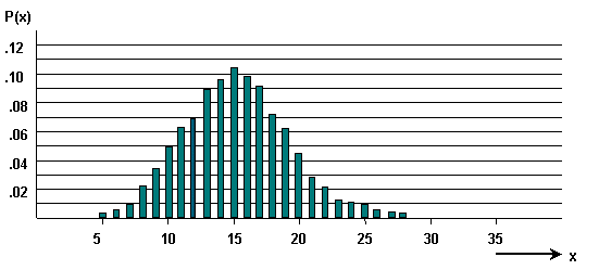
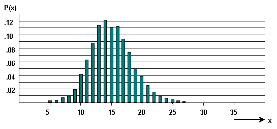
The second assumption deals with the traffic arrival characteristics. Usually, these assumptions are based on a Poisson traffic distribution where call arrivals follow a classic bell-shaped curve. Poisson distribution is commonly used for infinite traffic sources. In the three graphs here, the vertical axis shows the probability distribution and the horizontal axis shows the calls.
Random Traffic
Bunched calls result in traffic that has a smooth-shaped pattern. This pattern occurs more frequently with finite sources.
Smooth Traffic
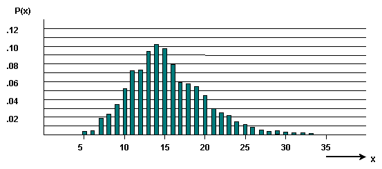
Peaked or rough traffic is represented by a skewed shape. This phenomenon occurs when traffic rolls from one trunk group to another.
Rough or Peaked Traffic
Handle Lost Calls
How to handle lost calls is the third assumption. The figure here depicts the three options available when the station you call does not answer:
-
Lost Calls Cleared (LCC).
-
Lost Calls Held (LCH).
-
Lost Calls Delayed (LCD).
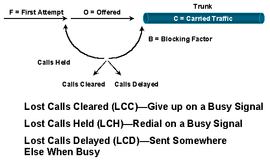
The LCC option assumes that once a call is placed and the server (network) is busy or not available, the call disappears from the system. In essence, you stop and do something different.
The LCH option assumes that a call is in the system for the duration of the hold time, regardless of whether or not the call is placed. In essence, you continue to redial for as long as the hold time before you stop.
Recalling, or redialing, is an important traffic consideration. Assume that 200 calls are attempted. Forty receive busy signals and attempt to redial. That results in 240 call attempts, a 20% increase. The trunk group now provides an even poorer GoS than initially thought.
The LCD option means that once a call is placed, it remains in a queue until a server is ready to handle it. Then it uses the server for the full holding time. This assumption is most commonly used for automatic call distribution (ACD) systems.
The assumption that the lost calls clear the system tends to understate the number of trunks required. On the other hand, LCH overstates the number.
How the Switch Handles Trunk Allocation
The fourth and final assumption centers around the switching equipment itself. In the circuit switch environment, many of the larger switches block switches. That is, not every input has a path to every output. Complex grading structures are created to help determine the pathways a circuit takes through the switch, and the impact on the GoS. In this example, assume that the equipment involved is fully non-blocking.
The purpose of the third step is to calculate the number of physical trunks required. You have determined the amount of offered traffic during the busy hour. You have talked to the customer. Therefore, you know the GoS the customer requests . ` Calculate the number of trunks required by using formulas or tables.
Traffic theory consists of many queuing methods and associated formulas. Tables that deal with the most commonly encountered model is presented here. The most commonly used model and table is Erlang B. It is based on infinite sources, LCC, and Poisson distribution that is appropriate for either exponential or constant holding times. Erlang B understates the number of trunks because of the LCC assumption. However, it is the most commonly used algorithm.
The example here determines the number of trunks in a trunk group that carry this traffic (a trunk group is defined as a hunt group of parallel trunks):
-
352 hours of offered call traffic in a month.
-
22 business days/month.
-
10% call processing overhead
-
15% of the traffic occurs in the busy hour.
-
Grade of service p=.01
Busy hour = 352 divided by 22 x 15% x 1.10 (call processing overhead) = 2.64 Erlangs
The traffic assumptions are:
-
Infinite sources.
-
Random or Poisson traffic distribution and lost calls are cleared.
Based on these assumptions, the appropriate algorithm to use is Erlang B. Use this table to determine the appropriate number of trunks (N) for a P of .01.
| N | P | |||||
|---|---|---|---|---|---|---|
| .003 | .005 | .01 | .02 | .03 | .05 | |
| 1 | .003 | .005 | .011 | .021 | .031 | .053 |
| 2 | .081 | .106 | .153 | .224 | .282 | .382 |
| 3 | .289 | .349 | .456 | .603 | .716 | .9 |
| 4 | .602 | .702 | .87 | 1.093 | 1.259 | 1.525 |
| 5 | .995 | 1.132 | 1.361 | 1.658 | 1.876 | 2.219 |
| 6 | 1.447 | 1.622 | 1.909 | 2.276 | 2.543 | 2.961 |
| 7 | 1.947 | 2.158 | 2.501 | 2.936 | 3.25 | 3.738 |
| 8 | 2.484 | 2.73 | 3.128 | 3.627 | 3.987 | 4.543 |
| 9 | 3.053 | 3.333 | 3.783 | 4.345 | 4.748 | 5.371 |
| 10 | 3.648 | 3.961 | 4.462 | 5.084 | 5.53 | 6.216 |
| 11 | 4.267 | 4.611 | 5.16 | 5.842 | 6.328 | 7.077 |
| 12 | 4.904 | 5.279 | 5.876 | 6.615 | 7.141 | 7.95 |
| 13 | 5.559 | 5.964 | 6.608 | 7.402 | 7.967 | 8.835 |
| 14 | 6.229 | 6.664 | 7.352 | 8.201 | 8.804 | 9.73 |
| 15 | 6.913 | 7.376 | 8.108 | 9.01 | 9.65 | 10.63 |
Note: Table is extracted from T. Frankel's "ABC of the Telephone"
Since a grade of service of P .01 is required, use only the column designated as P .01. The calculations indicate a busy hour traffic amount of 2.64 erlangs. This lies between 2.501 and 3.128 in the P .01 column. This corresponds to a number of trunks (N) of seven and eight. Since you are unable to use a fractional trunk, use the next larger value ( eight trunks) to carry the traffic.
There are several variations of Erlang B tables available to determine the number of trunks required to service a specific amount of traffic. The table here shows the relationship between GoS and the number of trunks (T) required to support a rate of traffic in erlangs.
| Traffic Rate In Erlangs | Number of Trunks (T) | |||||||||
|---|---|---|---|---|---|---|---|---|---|---|
| T=1 | T=2 | T=3 | T=4 | T=5 | T=6 | T=7 | T=8 | T=9 | T=10 | |
| 0.10 | .09091 | .00452 | .00015 | .00000 | .00000 | .00000 | .00000 | .00000 | .00000 | .00000 |
| 0.20 | .16667 | .01639 | .00109 | .00005 | .00000 | .00000 | .00000 | .00000 | .00000 | .00000 |
| 0.30 | .23077 | .03346 | .00333 | .00025 | .00002 | .00000 | .00000 | .00000 | .00000 | .00000 |
| 0.40 | .28571 | .05405 | .00716 | .00072 | .00006 | .00000 | .00000 | .00000 | .00000 | .00000 |
| 0.50 | .33333 | .07692 | .01266 | .00158 | .00016 | .00001 | .00000 | .00000 | .00000 | .00000 |
| 0.60 | .37500 | .10112 | .01982 | .00296 | .00036 | .00004 | .00000 | .00000 | .00000 | .00000 |
| 0.70 | .41176 | .12596 | .02855 | .000497 | .00070 | .00008 | .00001 | .00000 | .00000 | .00000 |
| 0.80 | .44444 | .15094 | .03869 | .00768 | .00123 | .00016 | .00002 | .00000 | .00000 | .00000 |
| 0.90 | .47368 | .17570 | .05007 | .01114 | .00200 | .00030 | .00004 | .00000 | .00000 | .00000 |
| 1.00 | .50000 | .20000 | .06250 | .01538 | .00307 | .00051 | .00007 | .00001 | .00000 | .00000 |
| 1.10 | .52381 | .22366 | .07579 | .02042 | .00447 | .00082 | .00013 | .00002 | .00000 | .00000 |
| 1.20 | .54545 | .24658 | .08978 | .02623 | .00625 | .00125 | .00021 | .00003 | .00000 | .00000 |
| 1.30 | .56522 | .26868 | .10429 | .03278 | .00845 | .00183 | .00034 | .00006 | .00001 | .00000 |
| 1.40 | .58333 | .28949 | .11918 | .40040 | .01109 | .00258 | .00052 | .00009 | .00001 | .00000 |
| 1.50 | .60000 | .31034 | .13433 | .04796 | .01418 | .00353 | .00076 | .00014 | .00002 | .00000 |
| 1.60 | .61538 | .32990 | .14962 | .05647 | .01775 | .00471 | .00108 | .00022 | .00004 | .00001 |
| 1.70 | .62963 | .34861 | .16496 | .06551 | .02179 | .00614 | .00149 | .00032 | .00006 | .00001 |
| 1.80 | .644286 | .36652 | .18027 | .07503 | .02630 | .00783 | .00201 | .00045 | .00009 | .00002 |
| 1.90 | .65517 | .38363 | .19547 | .08496 | .03128 | .00981 | .00265 | .00063 | .00013 | .00003 |
| 2.00 | .66667 | .40000 | .21053 | .09524 | .03670 | .01208 | .00344 | .00086 | .00019 | .00004 |
| 2.20 | .68750 | .43060 | .23999 | .11660 | .04880 | .01758 | .00549 | .00151 | .00037 | .00008 |
| 2.40 | .70588 | .45860 | .26841 | .13871 | .06242 | .02436 | .00828 | .00248 | .00066 | .00016 |
| 2.60 | .72222 | .48424 | .29561 | .16118 | .07733 | .03242 | .01190 | .00385 | .00111 | .00029 |
| 2.80 | .73684 | .50777 | .32154 | .18372 | .09329 | .04172 | .01641 | .00571 | .00177 | .00050 |
| 3.00 | .75000 | .52941 | .34615 | .20611 | .11005 | .05216 | .02186 | .00813 | .00270 | .00081 |
| 3.20 | .76190 | .54936 | .36948 | .22814 | .12741 | .06363 | .02826 | .01118 | .00396 | .00127 |
| 3.40 | .77273 | .56778 | .39154 | .24970 | .14515 | .07600 | .03560 | .01490 | .00560 | .00190 |
| 3.60 | .78261 | .58484 | .41239 | .27069 | .16311 | .08914 | .04383 | .01934 | .00768 | .00276 |
| 3.80 | .79167 | .60067 | .43209 | .29102 | .18112 | .10290 | .05291 | .02451 | .01024 | .00388 |
| 4.00 | .80000 | .61538 | .45070 | .31068 | .19907 | .11716 | .06275 | .03042 | .01334 | .00531 |
| Traffic Rate In Erlangs | Number of Trunks (T) | |||||||||
|---|---|---|---|---|---|---|---|---|---|---|
| T=11 | T=12 | T=13 | T=14 | T=15 | T=16 | T=17 | T=18 | T=19 | T=20 | |
| 4.00 | .00193 | .00064 | .00020 | .00006 | .00002 | .00000 | .00000 | .00000 | .00000 | .00000 |
| 4.50 | .00427 | .00160 | .00055 | .00018 | .00005 | .00002 | .00000 | .00000 | .00000 | .00000 |
| 5.00 | .00829 | .00344 | .00132 | .00047 | .00016 | .00005 | .00001 | .00000 | .00000 | .00000 |
| 5.25 | .01107 | .00482 | .00194 | .00073 | .00025 | .00008 | .00003 | .00001 | .00000 | .00000 |
| 5.50 | .01442 | .00657 | .00277 | .00109 | .00040 | .00014 | .00004 | .00001 | .00000 | .00000 |
| 5.75 | .01839 | .00873 | .00385 | .00158 | .00060 | .00022 | .00007 | .00002 | .00001 | .00000 |
| 6.00 | .02299 | .01136 | .00522 | .00223 | .00089 | .00033 | .00012 | .00004 | .00001 | .00000 |
| 6.25 | .02823 | .01449 | .00692 | .00308 | .00128 | .00050 | .00018 | .00006 | .00002 | .00001 |
| 6.50 | .03412 | .01814 | .00899 | .00416 | .00180 | .00073 | .00028 | .00010 | .00003 | .00001 |
| 6.75 | .04062 | .02234 | .01147 | .00550 | .00247 | .00104 | .00041 | .00015 | .00005 | .00002 |
| 7.00 | .04772 | .02708 | .01437 | .00713 | .00332 | .00145 | .00060 | .00023 | .00009 | .00003 |
| 7.25 | .05538 | .02827 | .01173 | .00910 | .00438 | .00198 | .00084 | .00034 | .00013 | .00005 |
| 7.50 | .06356 | .03821 | .02157 | .01142 | .00568 | .00265 | .00117 | .00049 | .00019 | .00007 |
| 7.75 | .07221 | .04456 | .02588 | .01412 | .00724 | .00350 | .00159 | .00068 | .00028 | .00011 |
| 8.00 | .08129 | .05141 | .03066 | .01722 | .00910 | .00453 | .00213 | .00094 | .00040 | .00016 |
| 8.25 | .09074 | .05872 | .03593 | .02073 | .01127 | .00578 | .00280 | .00128 | .00056 | .00023 |
| 8.50 | .10051 | .06646 | .04165 | .02466 | .01378 | .00727 | .00362 | .00171 | .00076 | .00032 |
| 8.75 | .11055 | .07460 | .04781 | .02901 | .01664 | .00902 | .00462 | .00224 | .00103 | .00045 |
| 9.00 | .12082 | .08309 | .05439 | .03379 | .01987 | .01105 | .00582 | .00290 | .00137 | .00062 |
| 9.25 | .13126 | .09188 | .06137 | .03897 | .02347 | .01338 | .00723 | .00370 | .00180 | .00083 |
| 9.50 | .14184 | .10095 | .06870 | .04454 | .02744 | .01603 | .00888 | .00466 | .00233 | .00110 |
| 9.75 | .15151 | .11025 | .07637 | .05050 | .03178 | .01900 | .01708 | .00581 | .00297 | .00145 |
| 10.00 | .16323 | .11974 | .08434 | .05682 | .03650 | .02230 | .01295 | .00714 | .00375 | .00187 |
| 10.25 | .17398 | .12938 | .09257 | .06347 | .04157 | .02594 | .01540 | .00869 | .00467 | .00239 |
| 10.50 | .18472 | .13914 | .10103 | .07044 | .04699 | .02991 | .01814 | .01047 | .00575 | .00301 |
| 10.75 | .19543 | .14899 | .10969 | .07768 | .05274 | .03422 | .02118 | .01249 | .00702 | .00376 |
| 11.00 | .20608 | .15889 | .11851 | .08519 | .05880 | .03885 | .02452 | .01477 | .00848 | .00464 |
| 11.25 | .21666 | .16883 | .12748 | .09292 | .06515 | .04380 | .02817 | .01730 | .01014 | .00567 |
| 11.75 | .22714 | .17877 | .13655 | .10085 | .07177 | .04905 | .03212 | .02011 | .01202 | .00687 |
| Traffic Rate In Erlangs | Number of Trunks (T) | |||||||||
|---|---|---|---|---|---|---|---|---|---|---|
| T=21 | T=22 | T=23 | T=24 | T=25 | T=26 | T=27 | T=28 | T=29 | T=30 | |
| 11.50 | .00375 | .00195 | .00098 | .00047 | .00022 | .00010 | .00004 | .00002 | .00001 | .00000 |
| 12.00 | .00557 | .00303 | .00158 | .00079 | .00038 | .00017 | .00008 | .00003 | .00001 | .00001 |
| 12.50 | .00798 | .00452 | .00245 | .00127 | .00064 | .00034 | .00014 | .00006 | .00003 | .00001 |
| 13.00 | .01109 | .00651 | .00367 | .00198 | .00103 | .00051 | .00025 | .00011 | .00005 | .00001 |
| 13.50 | .01495 | .00909 | .00531 | .00298 | .00160 | .00083 | .00042 | .00020 | .00009 | .00004 |
| 14.00 | .01963 | .01234 | .00745 | .00433 | .00242 | .00130 | .00067 | .00034 | .00016 | .00008 |
| 14.50 | .02516 | .01631 | .01018 | .00611 | .00353 | .00197 | .00105 | .00055 | .00027 | .00013 |
| 15.00 | .03154 | .02105 | .01354 | .00839 | .00501 | .00288 | .00160 | .00086 | .00044 | .00022 |
| 15.50 | .03876 | .02658 | .01760 | .01124 | .00692 | .00411 | .00235 | .00130 | .00069 | .00036 |
| 16.00 | .04678 | .03290 | .02238 | .01470 | .00932 | .00570 | .00337 | .00192 | .00106 | .00056 |
| 16.50 | .05555 | .03999 | .02789 | .01881 | .01226 | .00772 | .00470 | .00276 | .00157 | .00086 |
| 17.00 | .06499 | .04782 | .03414 | .02361 | .01580 | .01023 | .00640 | .00387 | .00226 | .00128 |
| 17.50 | .07503 | .05632 | .04109 | .02909 | .01996 | .01326 | .00852 | .00530 | .00319 | .00185 |
| 18.00 | .08560 | .06545 | .04873 | .03526 | .02476 | .01685 | .01111 | .00709 | .00438 | .00262 |
| 18.50 | .09660 | .07513 | .05699 | .04208 | .03020 | .02103 | .01421 | .00930 | .00590 | .00362 |
| 19.00 | .10796 | .08528 | .04952 | .03627 | .02582 | .01785 | .01785 | .01197 | .00788 | .00490 |
| 19.50 | .11959 | .09584 | .07515 | .05755 | .04296 | .03121 | .02205 | .01512 | .01007 | .00650 |
| 20.00 | .13144 | .10673 | .08493 | .06610 | .05022 | .03720 | .02681 | .01879 | .01279 | .00846 |
Note: This table is obtained from "Systems Analysis for Data Transmission," James Martin, Prentice-Hall, Inc. 1972, ISBN: 0-13-881300-0; Table 11. Probability of a Transaction Being Lost, P(n).
In most situations, a single circuit between units is enough for the expected number of voice calls. However, in some routes there is a concentration of calls that requires additional circuits to be added to provide a better GoS. A GoS in telephone engineering usually ranges from 0.01 to 0.001. This represents the probability of the number of calls that are blocked. In other words, .01 is one call in 100, and .001 is one call in 1000 that is lost due to blocking. The usual way to describe the GoS or blocking characteristics of a system is to state the probability that a call is lost when there is a given traffic load. P(01) is considered a good GoS, whereas P(001) is considered a non-blocking GoS.
4. Determine the proper mix of trunks.
The proper mix of trunks is more of an economic decision than a technical decision. Cost per minute is the most commonly used measurement in order to determine the price breakpoint of adding trunks. Ensure that all cost components are considered, such as accounting for additional transmission, equipment, administration, and maintenance costs.
There are two rules to follow when you optimize the network for cost:
-
Use average usage figures instead of the busy hour which overstates the number of call minutes.
-
Use the least costly circuit until the incremental cost becomes more expensive than the next best route.
Based on the previous example, providing a GoS of .01 requires 8 trunks if there are 2.64 erlangs of offered traffic. Derive an average usage figure:
-
352 hours divided by 22 days in a month divided by 8 hours in a day x 1.10 (call processing overhead) = 2.2 erlangs during the average hour.
Assume that the carrier (XYZ) offers these rates:
-
Direct distance dialing (DDD) = $25 per hour.
-
Savings Plan A = $60 fixed charge plus $18 per hour.
-
Tie trunk = $500 flat rate.
First, graph the costs. All the numbers are converted to hourly figures to make it easier to work with the erlang calculations.
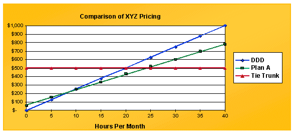
The Tie Trunk, represented by the red line, is a straight line at $500. DDD is a linear line that starts at 0. To optimize costs, the goal is to stay below the curve. The cross-over points between the different plans occur at 8.57 hours between DDD and Plan A, and 24.4 hours between Plan A and Tie Trunks.
The next step is to calculate the carried traffic on a per trunk basis. Most switches allocate voice traffic on a first-in-first-out (FIFO) basis. This means that the first trunk in a trunk group carries substantially more traffic than the last trunk in the same trunk group. Calculate the average allocation of traffic per trunk. It is difficult to do so without a program that calculates these figures on an iterative basis. This table shows the traffic distribution based on 2.2 erlangs using such a program:
Traffic on Each Trunk Based on 2.2 Erlangs
| Trunks | Offered Hours | Carried per Trunk | Cumulative Carried | GoS |
|---|---|---|---|---|
| 1 | 2.2 | 0.688 | 0.688 | 0.688 |
| 2 | 1.513 | 0.565 | 1.253 | 0.431 |
| 3 | 0.947 | 0.419 | 1.672 | 0.24 |
| 4 | 0.528 | 0.271 | 1.943 | 0.117 |
| 5 | 0.257 | 0.149 | 2.093 | 0.049 |
| 6 | 0.107 | 0.069 | 2.161 | 0.018 |
| 7 | 0.039 | 0.027 | 2.188 | 0.005 |
| 8 | 0.012 | 0.009 | 2.197 | 0.002 |
| 9 | 0.003 | 0.003 | 2.199 | 0 |
The first trunk is offered 2.2 hours and carries .688 erlangs. The theoretical maximum for this trunk is one erlang. The eighth trunk only carries .009 erlangs. An obvious implication when you design a data network to carry voice is that the specific trunk moved on to the data network can have a considerable amount of traffic carried, or next to nothing carried.
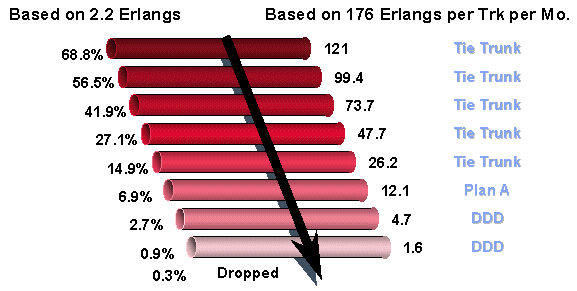
Using these figures and combining them with the break even prices calculated earlier, you can determine the appropriate mix of trunks. A trunk can carry 176 erlangs of traffic per month, based on 8 hours per day and 22 days per month. The first trunk carries .688 erlangs or is 68.8% effective. On a monthly basis, that equals 121 erlangs. The cross-over points are 24.4 and 8.57 hours. In this figure, tie trunks are still used at 26.2 erlangs. However, the next lower trunk uses Plan A because it drops below 24.4 hours. The same method applies to the DDD calculations.
Regarding voice over data networks, it is important to derive a cost per hour for the data infrastructure. Then, calculate the voice over X trunk as another tariffed option.
5. Equate erlangs of carried traffic to packets or cells per second.
The fifth and last step in traffic engineering is to equate erlangs of carried traffic to packets or cells per second. One way to do this is to convert one erlang to the appropriate data measurement, then apply modifiers. These equations are theoretical numbers based on pulse code modulation (PCM) voice and fully loaded packets.
-
1 PCM voice channel requires 64 kBps
-
1 erlang is 60 minutes of voice
Therefore, 1 erlang = 64 kBps x 3600 seconds x 1 byte/8 bits = 28.8 MB of traffic in one hour.
ATM using AAL1
-
1 Erlang = 655 KB cells/hour assuming a 44 byte payload
-
= 182 cells/sec
ATM using AAL5
-
1 Erlang = 600 KB cells/hour assuming a 47 byte payload
-
= 167 cells/second
Frame Relay
-
1 Erlang = 960 KB frames (30 byte payload) or 267 fps
IP
-
1 Erlang = 1.44 M packets (20 byte packets) or 400 pps
Apply modifiers to these figures based on the actual conditions. Types of modifiers to apply include packet overhead, voice compression, voice activity detection (VAD), and signaling overhead.
Packet overhead can be used as a percent modifier.
ATM
-
AAL1 has nine bytes for every 44 bytes of payload or has a 1.2 multiplier.
-
AAL5 has six bytes for every 47 bytes of payload or has a 1.127 multiplier.
Frame Relay
-
Four to six bytes of overhead, payload variable to 4096 bytes.
-
Using 30 bytes of payload and four bytes of overhead, it has a 1.13 multiplier.
IP
-
20 bytes for IP.
-
Eight bytes for User Datagram Protocol (UDP).
-
Twelve to 72 bytes for Real-Time Transport Protocol (RTP).
Without using Compressed Real-Time Protocol (CRTP), the amount of overhead is unrealistic. The actual multiplier is three. CRTP can reduce the overhead further, generally in the range of four to six bytes. Assuming five bytes, the multiplier changes to 1.25. Assume that you run 8 KB of compressed voice. You are unable to get below 10 KB if you factor in overhead. Consider Layer 2 overhead as well.
Voice compression and voice activity detection are also treated as multipliers. For example, conjugate structure algebraic code excited linear prediction (CS-ACELP) ( 8 KB voice) is considered a .125 multiplier. VAD can be considered a .6 or .7 multiplier.
Factor in signaling overhead. In particular, VoIP needs to figure in the Real Time Control Protocol (RTCP) and the H.225 and H.245 connections.
The final step is to apply traffic distribution to the trunks to see how it equates to bandwidth. This diagram shows the traffic distribution based on busy hour and average hour calculations. For the busy hour calculations, the program that shows the distribution of traffic per trunk based on 2.64 erlangs is used.
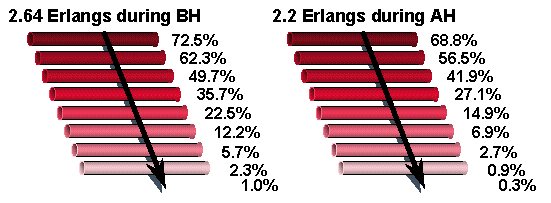
BH = Busy Hour
AH = Average Hour
Using the average hour figures as an example, there are .688 erlangs on the first trunk. This equates to 64 kBps x .688 = 44 kBps. 8 KB voice compression equates to 5.5 kBps. IP overhead factored in brings the number up to 6.875 kBps. With voice trunks, the initial trunks carry high traffic only in larger trunk groups.
When you work with voice and data managers, the best approach to take when you calculate voice bandwidth requirements is to work through the math. Eight trunks are needed at all times for peak traffic intensity. Using PCM voice results in 512 KB for eight trunks. The busy hour uses 2.64 erlangs, or 169 kBps of traffic. On average, you use 2.2 erlangs or 141 kBps of traffic.
2.2 erlangs of traffic carried over IP using voice compression requires this bandwidth:
-
141 kBps x .125 (8 KB voice) x 1.25 (overhead using CRTP) = 22 kBps
Other modifiers that need to be accounted for include:
-
Layer 2 overhead
-
Call setup and tear down signaling overhead
-
Voice activity detection (if used)
Gain/Loss Plan
In today's customer private networks, attention must be given to transmission parameters, such as end-to-end loss and propagation delay. Individually, these characteristics hinder the efficient transfer of information through a network. Together, they manifest themselves as an even more detrimental obstruction referred to as "echo."
Loss is introduced into transmission paths between end offices (EO) primarily to control echo and near-singing (Listener Echo). The amount of loss needed to achieve a given talker-echo GoS increases with delay. However, the loss also attenuates the primary speech signal. Too much loss makes it difficult to hear the speaker. The degree of difficulty depends upon the amount of noise in the circuit. The joint effect of loss, noise, and talker-echo is assessed through the loss-noise-echo GoS measure. The development of a loss plan takes into account the joint customer perception effect of the three parameters (loss, noise, and talker echo). A loss plan needs to provide a value of connection loss that is close to the optimum value for all connection lengths. At the same time, the plan must be easy enough to implement and administer. The information here helps you to design and implement the Cisco MC3810 into a customer private network.
Private Branch Exchanges
A PBX is an assembly of equipment that allows an individual within a community of users to originate and answer calls to and from the public network ( through central office, wide-area telephone service (WATS), and FX trunks), special service trunks, and other users (PBX lines) within the community. Upon dial initiation, the PBX connects the user to an idle line or to an idle trunk in an appropriate trunk group. It returns the appropriate call status signal, such as a dial tone or audible ring. A busy indication is returned if the line or trunk group is busy. An attendant position can be provided to answer incoming calls and for user assistance. There are both Analog and Digital PBXs. An Analog PBX (APBX) is a dial PBX that uses analog switching to make call connections. A Digital PBX (DPBX) is a dial PBX that uses digital switching to make call connections. PBXs function in one of three ways: Satellite, Main, and Tandem.
A Satellite PBX is homed on a Main PBX through which it receives calls from the public network and can connect to other PBXs in a private network.
A Main PBX functions as the interface to the Public Switched Telephone Network (PSTN). It supports a specific geographic area. It can support a subtending Satellite PBX as well as function as a Tandem PBX.
A Tandem PBX functions as a through-point. Calls from one Main PBX are routed through another PBX to a third PBX. Therefore, the word Tandem.
PBX Interfaces
PBX interfaces are broken into four major categories:
-
Tie Trunk Interfaces
-
Public Network Interfaces
-
Satellite PBX Interfaces
-
Line Interfaces
This document focuses on the Tie Trunk and Satellite PBX Interfaces. There are four major interfaces in these two categories:
-
S/DTT - Digital trunk interface to digital Satellite PBX tie trunk.
-
S/ATT - Analog trunk interface to analog Satellite PBX tie trunk.
-
D/TT - Digital trunk interface to non-ISDN digital or combination tie trunk.
-
A/TT - Analog trunk interface to tie trunk.
PBX Interface Levels
__________

                       |         |

                       |         | ------>    0 dB  D/TT, S/DTT

                       |         | <------    0 dB

                -------|         |

                |                | ------>   -2 dB  A/TT , S/ATT,  S/DTT (with CB)

                |________________| <------   -2 dB
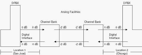
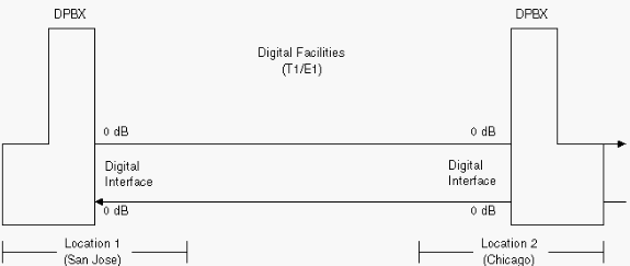
The interfaces and levels expected by DPBXs are listed first in order to help design and implement the Cisco MC3810s with the correct transmit and receive levels. DPBXs with pure digital tie trunks (no analog-to-digital conversions) always receive and transmit at 0 dB (D/TT), as illustrated in the previous figure.
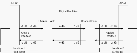
For DPBXs with hybrid tie trunks (analog-to-digital conversion), the transmit and receive levels are also 0 dB if the Channel Bank (CB) interface connects to the DPBX digitally at both ends and an Analog Tie Trunk is used (see the next figure). If the CB connects to the DPBX through an analog interface, the levels are -2.0 dB for both transmit and receive (see this figure).
DPBXs with Hybrid Tie Trunks
Channel Bank Connects to the DPBX Through an Analog Interface

If there is only one CB and it connects to a DPBX through an analog interface, the levels are -2.0 dB transmit and -4.0 receive (see this figure).
One CB Connected to a DPBX Through an Analog Interface
Design and Install the Cisco MC3810
When you implement Cisco MC3810s into a customer network, you must first understand the existing network loss plan to ensure that an end-to-end call still has the same overall loss or levels when the Cisco MC3810s are installed. This process is called baselining or benchmarking. One way to benchmark is to draw all of the network components before you install the Cisco MC3810. Then document the expected levels at key access and egress points in the network, based on Electronic Industries Association and Telecommunications Industry Association (EIA/TIA) standards. Measure the levels at these same access and egress points in the network to ensure that they are properly documented (see this figure). Once the levels are measured and documented, install the Cisco MC3810. Once installed, adjust the levels of the Cisco MC3810 to match the levels previously measured and documented (see this figure).
Network Components Before you Install the Cisco MC3810
Network Components After you Install the Cisco MC3810
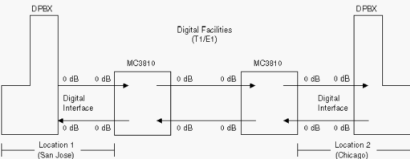
For the majority of Cisco MC3810 implementations, DPBXs are part of the overall customer network. For example, the network topology can look like this:
DPBX (Location 1) connects to a Cisco MC3810 (Location 1). This connects to a facility/trunk (digital or analog) to a distant end (Location 2). The facility/trunk is connected to another Cisco MC3810. This is connected to another DPBX (Location 2). In this scenario, the levels (transmit and receive) that are expected at the DPBX are determined by the facility/trunk type or interface (as illustrated in the previous figure).
The next step is to start the design:
-
Diagram the existing network with all of the transmission equipment and facility connections included.
-
Using the information listed above and in the EIA/TIA Standards (EIA/TIA 464-B and EIA/TIA Telecommunications Systems Bulletin No. 32 - Digital PBX Loss Plan Application Guide), list the expected levels (for both egress and access interfaces) for each piece of transmission equipment.
-
Measure the actual levels to ensure that the expected levels and the actual levels are the same. If they are not, go back and review the EIA/TIA documents for the type of configuration and interface. Make level adjustments as necessary. If they are the same, document the levels and move on to the next piece of equipment. Once you have documented all of the measured levels in the network and they are consistent with the expected levels, you are ready to install the Cisco MC3810.
Install the Cisco MC3810 and adjust the levels to match the levels measured and documented prior to installation. This ensures that the overall levels are still consistent with those of the benchmark levels. Make a call through test to ensure the Cisco MC3810 operates efficiently. If not, go back and recheck the levels to ensure they are set correctly.
The Cisco MC3810 can also be used to interface to the PSTN. It is designed to have - 3 dB on Foreign Exchange Station (FXS) ports, and 0 dB for Foreign Exchange Office (FXO) and recEive and transMit (E&M) ports. For analog, these values are true for both directions. For digital, the value is 0 dB. The Cisco MC3810 has a dynamic command to show the actual gain (show voice call x/y) to allow a technician to hold a digit key and watch the actual gain for various DTMF tones.
Internal built-in interface offsets for the Cisco MC3810 are listed here:
-
FXO input gain offset = 0.7 dBm FXO output attenuation offset = - 0.3 dBm
-
FXS input gain offset = -5 dBm FXS output attenuation offset = 2.2 dBm
-
E&M 4w input gain offset = -1.1 dBm E&M 4w output attenuation offset = - 0.4dBm
The Voice Quality Testbed (VQT) system is a tool to make objective audio measurements on a variety of audio transmission devices and networks. Some examples include:
-
The measurement of end-to-end audio delay in a packet switched network.
-
The measurement of the frequency response of a plain old telephone service (POTS) channel.
-
The measurement of the effectiveness and speed of a telephone network echo canceller.
-
The measurement of the acoustic impulse response of a speaker phone terminal.
Clocking Plan
Hierarchical Synchronization
The hierarchical synchronization method consists of four stratum levels of clocks. It is selected to synchronize the North American networks. It is consistent with the current industry standards.
In the hierarchical synchronization method, frequency references are transmitted between nodes. The highest level clock in the synchronization hierarchy is a Primary Reference Source (PRS). All interconnecting digital synchronization networks need to be controlled by a PRS. A PRS is equipment that maintains a long-term frequency accuracy of 1x10-11 or better with optional verification to Coordinated Universal Time (UTC) and meets current industry standards. This equipment can be a stratum 1 clock (Cesium standard) or can be equipment directly controlled by standard UTC-derived frequency and time services, such as LORAN-C or Global Positioning Satellite System (GPS) radio receivers. The LORAN-C and GPS signals themselves are controlled by Cesium standards that are not a part of the PRS since they are physically removed from it. Because primary reference sources are stratum 1 devices or are traceable to stratum 1 devices, every digital synchronization network controlled by a PRS has stratum 1 traceability.
Stratum 2 nodes form the second level of the synchronization hierarchy. Stratum 2 clocks provide synchronization to:
-
Other stratum 2 devices.
-
Stratum 3 devices, such as Digital Crossconnect Systems (DCSs) or digital end offices.
-
Stratum 4 devices, such as channel banks or DPBXs.
Similarly, stratum 3 clocks provide synchronization to other stratum 3 devices and/or to stratum 4 devices.
One attractive feature of hierarchical synchronization is that existing digital transmission facilities between digital switching nodes can be used for synchronization. For example, the basic 1.544 MB/s line rate (8000-frame-per-second frame rate) of a T1 Carrier System can be used for this purpose without diminishing the traffic carrying capacity of that carrier system. Hence, separate transmission facilities do not need to be dedicated for synchronization. However, synchronization interfaces between public and private networks need to be coordinated because of certain digital transmission facility characteristics, such as facility trouble history, pointer adjustments, and the number of switching points.
Reliable operation is crucial to all parts of a telecommunications network. For this reason, the synchronization network includes primary and secondary (backup) synchronization facilities to each Stratum 2 node, many Stratum 3 nodes, and Stratum 4 nodes, where applicable. In addition, each Stratum 2 and 3 node is equipped with an internal clock that bridges short disruptions of the synchronization references. This internal clock is normally locked to the synchronization references. When the synchronization reference is removed, the clock frequency is maintained at a rate determined by its stability.
Source of PRS-Traceable References
Private digital networks, when interconnected with PRS-traceable local exchange carrier/ International Electrotechnical Commission (LEC/IEC) networks, need to be synchronized from a reference signal traceable to a PRS. Two methods can be employed to achieve PRS traceability:
-
Provide a PRS clock, in which case the network operates plesiochronously with the LEC/IEC networks.
-
Accept PRS-traceable timing from the LEC/IEC networks.
Synchronization Interface Considerations
There are fundamentally two architectures that can be used to pass timing across the interface between LEC/IEC and the private network. The first is for the network to accept a PRS-traceable reference from an LEC/IEC at one location and to then provide timing references to all other equipment over interconnecting facilities. The second is for the network to accept a PRS-traceable reference at each interface with an LEC/IEC.
In the first method, the private network has control of the synchronization of all equipment. However, from a technical and maintenance viewpoint, there are limitations. Any loss of the distribution network causes all of the associated equipment to slip against the LEC/IEC networks. This problem causes troubles that are difficult to detect.
In the second method, PRS-traceable references are provided to the private network at each interface with an LEC/IEC. In this arrangement, the loss of a PRS-traceable reference causes a minimum of troubles. Additionally, the slips against the LEC/IEC occur at the same interface as the source of the trouble. This makes trouble location and subsequent repairs easier.
Signaling
Signaling is defined by CCITT Recommendation Q.9 as "the exchange of information (other than speech) specifically concerned with the establishment, release, and control of calls, and network management in automatic telecommunications operations."
In the broadest sense, there are two signaling realms:
-
Subscriber signaling
-
Trunk signaling (interswitch and/or interoffice)
Signaling is also traditionally classified into four basic functions:
-
Supervision
-
Address
-
Call Progress
-
Network Management
Supervision signaling is used to:
-
Initiate a call request on line or trunks (called line signaling on trunks)
-
Hold or release an established connection
-
Initiate or terminate charging
-
Recall an operator on an established connection
Address signaling conveys such information as the calling or called subscriber's telephone number and an area code, an access code, or a Private Automatic Branch Exchange (PABX) tie trunk access code. An address signal contains information that indicates the destination of a call initiated by a customer, network facility, and so forth.
Call progress signals are usually audible tones or recorded announcements that convey call-progress or call-failure information to subscribers or operators. These call-progress signals are fully described .
Network management signals are used to control the bulk assignment of circuits or to modify the operating characteristics of switching systems in a network in response to overload conditions.
There are about 25 recognized interregister signaling systems worldwide, in addition to some subscriber signaling techniques. CCITT Signaling System Number 7 (SSN7) is fast becoming the international/national standard interregister signaling system.
Most installations will probably involve E&M signaling. However, for reference, single frequency (SF) signaling on Tip and Ring loops, Tip and Ring reverse battery loops, loop start, and ground start are also included.
Types I and II are the most popular E&M signaling in the Americas. Type V is used in the United States. It is also very popular in Europe. SSDC5A differs in that on- and off-hook states are reversed to allow for fail-safe operation. If the line breaks, the interface defaults to off-hook (busy). Of all the types, only II and V are symmetrical ( can be back-to-back using a cross-over cable). SSDC5 is most often found in England.
Other signaling techniques often used are delay, immediate, and wink start. Wink start is an in-band technique where the originating device waits for an indication from the called switch before it sends the dialed digits. Wink start normally is not used on trunks that are controlled with message-oriented signaling schemes such as ISDN or Signaling System 7 (SS7).
Summary of Signaling System Applications and Interfaces
| Signaling System Application/Interface | Characteristics | |
|---|---|---|
| Station Loop | ||
| Loop Signaling | ||
| Basic Station | DC signaling. Origination at station. Ringing from Central Office. | |
| Coin Station | DC signaling. Loop-start or ground-start origination at station. Ground and simplex paths are used in addition to the line for coin collection and return. | |
| Interoffice Trunk | ||
| Loop Reverse Battery | One-way call origination. Directly applicable to metallic facilities. Both current and polarity are sensed. Used on carrier facilities with appropriate facility signaling system. | |
| E&M Lead | Two way call origination. Requires facility signaling system for all applications. | |
| Facility | Signaling System | |
| Metallic | DX | |
| Analog | SF | |
| Digital | Bits in information | |
| Special Service | ||
| Loop Type | Standard station loop and trunk arrangement as above. Ground-start format similar to coin service for PBX-CO trunks. | |
| E & M Lead | E&M for PBX dial tie trunks. E&M for carrier system channels in special service circuits. | |
North American Practices
The typical North American touchtone set provides a 12-tone set. Some custom sets provide 16-tone signals of which the extra digits are identified by the A-D push buttons.
DTMF Pairs
| Low Frequency Group (Hz) | High Frequency Group (Hz) | |||
|---|---|---|---|---|
| 1209 | 1336 | 1477 | 1633 | |
| 697 | 1 | 2 | 3 | A |
| 770 | 4 | 5 | 6 | B |
| 852 | 7 | 8 | 9 | C |
| 941 | * | 0 | # | D |
Audible Tones Commonly Used in North America
| Tone | Frequencies (Hz) | Cadence |
|---|---|---|
| Dial | 350 + 440 | Continuous |
| Busy (station) | 480 + 620 | 0.5 sec on, 0.5 sec off |
| Busy (network) | 480 + 620 | 0.2 sec on, 0.3 sec off |
| Ring return | 440 + 480 | 2 sec on, 4 sec off |
| Off-hook alert | Multifreq howl | 1 sec on, 1 sec off |
| Recording warning | 1400 | 0.5 sec on, 15 sec off |
| Call waiting | 440 | 0.3 sec on, 9.7 sec off |
Call Progress Tones Used in North America
| Name | Frequencies (Hz) | Pattern | Levels |
|---|---|---|---|
| Low tone | 480 + 620 600 x 120 600 x 133 600 x 140 600 x 160 | Various | -24 dBm0 61 to 71 dBmC 61 to 71 dBmC 61 to 71 dBmC 61 to 71 dBmC |
| High tone | 480 400 500 | Various | -17 dBmC 61 to 71 dBmC 61 to 71 dBmC |
| Dial tone | 350 + 440 | Steady | -13 dBm0 |
| Audible ring tone | 440 + 480 440 + 40 500 + 40 | 2 sec on, 4 sec off 2 sec on, 4 sec off 2 sec on, 4 sec off | -19 dBmC 61 to 71 dBmC 61 to 71 dBmC |
| Line Busy Tone | 480 + 620 600 x 120 600 x 133 600 x 140 600 x 160 | 0.5 sec on, 0.5 sec off | |
| Reorder | 480 + 620 600 x 120 600 x 133 600 x 140 600 x 160 | 0.3 sec on, 0.2 sec off | |
| 6A alerting tone | 440 | 2 sec on, followed by 0.5 sec on, every 10 sec | |
| Recorder warning tone | 1400 | 0.5 sec burst every 15 sec | |
| Reverting tone | 480 + 620 600 x 120 600 x 133 600 x 140 600 x 160 | 0.5 sec on, 0.5 sec off | -24 dBmC |
| Deposit coin tone | 480 + 620 600 x 120 600 x 133 600 x 140 600 x 160 | Steady | |
| Receiver off-hook (analog) | 1400 + 2060 + 2450 + 2600 | 0.1 sec on, 0.1 sec off | +5 vu |
| Receiver off-hook | 1400 + 2060 + 2450 + 2600 | 0.1 sec on, 0.1 sec off | +3.9 to -6.0 dBm |
| Howler | 480 | Incremented in level Every 1 sec for 10 sec | Up to 40 vu |
| No such number (crybaby) | 200 to 400 | Freq. modulated at 1 hz interrupted every 6 sec for 0.5 sec | |
| Vacant code | 480 + 620 600 x 120 600 x 133 600 x 140 600 x 160 | 0.5 sec on, 0.5 sec off, 0.5 sec on, 1.5 sec off? | |
| Busy verification Tone (Centrex) | 440 | Initial 1.5 sec followed 0.3 sec every 7.5 to 10 sec | -13 dBm0 |
| Busy verification Tone (TSPS) | 440 | Initial 2 sec followed 0.5 sec every 10 sec | -13 dBm0 |
| Call waiting tone | 440 | Two bursts of 300 ms separated by 10 sec | -13 dBm0 |
| Confirmation tone | 350 + 440 | 3 bursts of 300 ms separated by 10 sec | -13 dBm0 |
| Indication of camp-on | 440 | 1 sec every attendant releases from loop | -13 dBm0 |
| Recall dial tone | 350 + 440 | 3 bursts, 0.1 sec on, sec off then steady | -13 dBm0 |
| Data set answer back tone | 2025 | Steady | -13 dBm |
| Calling card prompt tone | 941 + 1477 followed by 440 + 350 | 60 ms | -10 dBm0 |
| Class of Service | 480 400 500 | 0.5 to 1 sec once | |
| Order tones | |||
| Single | 480 400 500 | 0.5 sec | |
| Double | 480 400 500 | 2 short bursts | |
| Triple | 480 400 500 | 3 short bursts | |
| Quad | 480 400 500 | 4 short bursts | |
| Number checking tone | 135 | Steady | |
| Coin denomination | |||
| 3 5 cents | 1050-1100 (bell) | One tap | |
| slot 10 cents | 1050-1100 (bell) | Two taps | |
| stations 25 cents | 800 (gong) | One tap | |
| Coin collect tone | 480 + 620 600 x 120 600 x 133 600 x 140 600 x 160 | Steady | |
| Coin return tone | 480 400 500 | 0.5 to 1 sec once | |
| Coin return test tone | 480 400 500 | 0.5 to 1 sec once | |
| Group busy tone | 480 + 620 600 x 120 600 x 133 600 x 140 600 x 160 | Steady | |
| Vacant position | 480 + 620 600 x 120 600 x 133 600 x 140 600 x 160 | Steady | |
| Dial off normal | 480 + 620 600 x 120 600 x 133 600 x 140 600 x 160 | Steady | |
| Permanent signal | 480 400 500 | Steady | |
| Warning tone | 480 400 500 | Steady | |
| Service observing | 135 | Steady | |
| Proceed to send Tone (IDDD) | 480 | Steady | -22 dBm0 |
| Centralized intercept | 1850 | 500 ms | -17 dBm0 |
| ONI order tone | 700 + 1100 | 95 to 250 ms | -25 dBm0 |
Note: Three dots in the pattern mean that the pattern is repeated indefinitely.
Single Frequency In-Band Signaling
SF in-band signaling is widely used in North America. Its most common application is for supervision, such as idle-busy, also called line signaling. It can also be used for dial pulse signaling on trunks. The dynamics of SF signaling requires an understanding of the signal durations and configurations of the E&M circuits, as well as the lead interface arrangements. These tables show the characteristics of SF signaling, E&M lead configurations, and interface arrangements.
Typical Single Frequency Signaling Characteristics
| General | |
| Signaling frequency (tone) | 2600 Hz |
| Idle state transmission | Cut |
| Idle/break | Tone |
| Busy/make | No Tone |
| Receiver | |
| Detector bandwidth | +/- 50 Hz @ -7 dBm for E type +/- 30 Hz @ -7 dBm |
| Pulsing rate | 7.5 to 122 pps |
| E/M unit | |
| Minimum time for on-hook | 33 ms |
| Minimum no tone for off-hook | 55 ms |
| Input percent break (tone) | 38-85 (10 pps) |
| E lead - open | Idle |
| - ground | Busy |
| Originating (loop reverse battery) unit | |
| Minimum tone for idle | 40 ms |
| Minimum no tone for off-hook | 43 ms |
| Minimum output for on-hook | 69 ms |
| Voltage on R lead (-48 V on ring and ground on tip) | On-hook |
| Voltage on T lead (-48 V on tip and ground on ring) | Off-hook |
| Terminating (loop reverse battery) unit | |
| Minimum tone for on-hook | 90 ms |
| Minimum no tone for off-hook | 60 ms |
| Minimum output (tone-on) | 56 ms |
| Loop open | On-hook |
| Loop closed | Off-hook |
| Transmitter | |
| Low level tone | -36 dBm |
| High level tone | -24 dBm |
| High level tone duration | 400 ms |
| Precut | 8 ms |
| Holdover cut | 125 ms |
| Crosscut | 625 ms |
| On hook cut | 625 ms |
| E/M unit | |
| Voltage on M lead | Off-hook (no tone) |
| Open/ground on M lead | On-hook (tone) |
| Minimum ground on M lead | 21 ms |
| Minimum voltage on M lead | 21 ms |
| Minimum output tone | 21 ms |
| Minimum no tone | 21 ms |
| Originating (loop reverse battery) unit | |
| Loop current to no tone | 19 ms |
| No loop current to tone | 19 ms |
| Minimum input for tone out | 20 ms |
| Minimum input for no tone out | 14 ms |
| Minimum tone out | 51 ms |
| Minimum no tone out | 26 ms |
| Loop open | On-hook |
| Loop closed | Off-hook |
| Terminating (loop) unit | |
| Reverse battery to no tone | 19 ms |
| Normal battery to tone | 19 ms |
| Minimum battery for tone out | 25 ms |
| Minimum reverse battery for no tone | 14 ms |
| Minimum tone out | 51 ms |
| Minimum no tone out | 26 ms |
| Battery on R lead (-48 v) | On-hook |
| Battery on TY lead (-48 on tip | Off-hook |
Single Frequency Signals Used in E&M Lead Signaling
| Calling End | Called End | ||||||
|---|---|---|---|---|---|---|---|
| Signal | M-Lead | E-Lead | 2600 Hz | 2600 Hz | E-Lead | M-Lead | Signal |
| Idle | Ground | Open | On | On | Open | Ground | Idle |
| Connect | Battery | Open | Off | On | Ground | Ground | Connect |
| Stop dialing | Battery | Ground | Off | Off | Ground | Battery | Stop dialing |
| Start dialing | Battery | Open | Off | On | Ground | Ground | Start Dialing |
| Dial pulsing | Ground | Open | On | On | Open | Ground | Dial pulsing |
| Battery | Off | Ground | |||||
| Off -hook | Battery | Ground | Off | Off | Ground | Battery | Off-hook (answer) |
| Ring forward | Ground | Ground | On | Off | Open | Battery | Ring forward |
| Battery | Off | Ground | |||||
| Ringback | Battery | Open | Off | On | Ground | Ground | Ringback |
| Ground | Off | Battery | |||||
| Flashing | Battery | Open | Off | On | Ground | Ground | Flashing |
| Ground | Off | Battery | |||||
| On-hook | Battery | Open | Off | On | Ground | Ground | On-hook |
| Disconnect | Ground | Open | On | On | Open | Ground | Disconnect |
Single Frequency Signals Used in Reverse Battery Tip and Ring Loop Signaling
| Calling End | Called End | ||||||
|---|---|---|---|---|---|---|---|
| Signal | T/R - SF | SF - T/R | 2600 Hz | 2600 Hz | T/R - SF | SF - T/R | Signal |
| Idle | Open | Batt-gnd | On | On | Open | Batt-gnd | Idle |
| Connect | Closure | Batt-gnd | Off | On | Closure | Batt-gnd | Connect |
| Stop dialing | Closure | Rev batt-gnd | Off | Off | Closure | Rev batt-gnd | Stop dialing |
| Start dialing | Closure | Batt-gnd | Off | On | Closure | Batt-gnd | Start dialing |
| Dial pulsing | Open | Batt-gnd | On | On | Open | Batt-gnd | Dial pulsing |
| Closure | Off | Closure | |||||
| Off-hook | Closure | Rev batt-gnd | Off | Off | Closure | Rev batt-gnd | Off-hook (answer) |
| Ring forward | Open | Rev batt-gnd | On | Off | Open | Rev batt-gnd | Ring forward |
| Closure | Off | Closure | |||||
| Ringback | Closure | Batt-gnd | Off | On | Closure | Batt-gnd | Ringback |
| Rev batt-gnd | Off | Rev batt-gnd | |||||
| Flashing | Closure | Batt-gnd | Off | On | Closure | Batt-gnd | Flashing |
| Rev batt-gnd | Off | Rev batt-gnd | |||||
| On-hook | Closure | Batt-gnd | Off | On | Closure | Batt-gnd | On-hook |
| Disconnect | Open | Batt-gnd | On | On | Open | Batt-gnd | Disconnect |
Single Frequency Signals Used for Ringing and Loop-Start Signaling Using Tip and Ring Leads - Call Originating at Central Office End
| Signal | T/R - SF | SF - T/R | 2600 Hz | 2600 Hz | T/R - SF | SF - T/R | Signal |
|---|---|---|---|---|---|---|---|
| Idle | Gnd-batt | Open | Off | On | Gnd-batt | Open | Idle |
| Seizure | Gnd-batt | Open | Off | On | Gnd-batt | Open | Idle |
| Ringing | Gnd-batt and 20 Hz | Open | On-off | On | Gnd-batt and 20 Hz | Open | Ringing |
| Off-hook (ring-trip and talk) | Gnd-batt | Closure | Off | Off | Gnd-batt | Closure | Off-hook (ring-trip and answer) |
| On-hook | Gnd-batt | Closure | Off | Off | Gnd-batt | Closure | Off-hook |
| On-hook (hang-up) | Gnd-batt | Open | Off | On | Gnd-batt | Open | On-hook (hang-up) |
Note: 20 Hz ringing (2 sec on, 4 sec off)
Single Frequency Signals Used for Ringing and Loop-Start Signaling Using Tip and Ring Leads - Call Originating at Station End
| Signal | T/R - SF | SF - T/R | 2600 Hz | 2600 Hz | T/R - SF | SF - T/R | Signal |
|---|---|---|---|---|---|---|---|
| Idle | Open | Gnd-batt | On | Off | Open | Gnd-batt | Idle |
| Off-hook (seizure) | Closure | Gnd-batt | Off | Off | Closure | Gnd-batt | Idle |
| Start dial | Closure | Dial tone and gnd-batt | Off | Off | Closure | Dial tone and gnd-batt | Start dial |
| Dial pulsing | Open-closure | Gnd-batt | On-off | Off | Open-closure | Gnd-batt | Dial pulsing |
| Waiting answer | Closure | Audible ring and gnd-batt | Off | Off | Closure | Audible ring and gnd-batt | Waiting answer |
| On-hook (talk) | Closure | Gnd-batt | Off | Off | Closure | Gnd-batt | Off-hook (answered) |
| On-hook (hang up) | Open | Gnd-batt Closure | On | Off | Open | Gnd-batt | On-hook (disconnected) Off-hook |
Single Frequency Signals Used for Ringing and Ground-Start Signaling Using Tip and Ring Leads - Call Originating at Central Office End
| Signal | T/R - SF | SF - T/R | 2600 Hz | 2600 Hz | T/R - SF | SF - T/R | Signal |
|---|---|---|---|---|---|---|---|
| Idle | Open-batt | Batt-batt | On | On | Open-batt | Idle | |
| Seizure | Gnd-batt | Open | On | On | Gnd-batt | Make-busy | |
| Ringing | Gnd-batt and 20 Hz | Open | On and 20 Hz | On | Gnd-batt and 20 Hz | Open | Ringing |
| Off-hook (ring-trip and talk) | Gnd-batt | Closure | Off | Off | Gnd-batt | Closure | Off-hook (ring-trip and answer) |
| On-hook | Gnd-batt | Closure | On | Off | Open-batt | Closure | On-hook |
| On-hook (hang-up) | Gnd-batt | Open | Off | On | Gnd-batt | Open | On-hook (hang-up) |
Note: 20 Hz ringing (2 sec on, 4 sec off)
Single Frequency Signals Used for Ringing and Ground-Start Signaling Using Tip and Ring Leads - Call Originating at Station End
| Signal | T/R - SF | SF - T/R | 2600 Hz | 2600 Hz | T/R - SF | SF - T/R | Signal |
|---|---|---|---|---|---|---|---|
| Idle | Open-batt | On | On | Batt-batt | Open-batt | Idle | |
| Off-hook (seizure) | Ground | Open-batt | Off | On | Batt-batt | Open-batt | Seizure |
| Start dial | Closure | Dial tone and gnd-batt | Off | Off | Closure | Dial tone and gnd-batt | Start dial |
| Dial pulsing | Open-closure | Gnd-batt | On-off | Off | Open-closure | Gnd-batt | Dial pulsing |
| Waiting answer | Closure | Audible ring and gnd-batt | Off | Off | Closure | Audible ring and gnd-batt | Waiting answer |
| Off-hook (talk) | Closure | Gnd-batt | Off | Off | Closure | Gnd-batt | Off-hook (answered) |
| On-hook | Closure | Open-batt | On | On | Batt-batt | Open-batt | On-hook (disconnected) |
| On-hook (disconnected) | Closure | On | Off | Open-batt | Open-batt | On-hook |
Site Preparation Guide
Download these checklists and forms (Adobe Acrobat PDF files) to plan for the installation of a Cisco MC3810 at a new site:
-
Cisco MC3810 Multiservice Concentrator Site Preparation Checklist
-
Cisco MC3810 Multiservice Concentrator Site Preparation Summary
Hunting Groups and Preference Configuration
The Cisco MC3810 supports the concept of hunting groups. This is the configuration of a group of dial peers on the same PBX with the same destination pattern. With a hunting group, if a call attempt is made to a dial peer on a specific digital signal level 0 (DS-0) timeslot and that timeslot is busy, the Cisco MC3810 hunts for another timeslot on that channel until an available timeslot is found. In this case, each dial peer is configured using the same destination pattern of 3000. It forms a dial pool to that destination pattern. To provide specific dial peers in the pool with a preference over other dial peers, configure the preference order for each dial peer using the preference command. The preference value is between zero and ten. Zero means the highest priority. This is an example of the dial peer configuration with all dial peers having the same destination pattern, but with different preference orders:
dial-peer voice 1 pots

destination pattern 3000

port 1/1

preference 0


dial-peer voice 2 pots

destination pattern 3000

port 1/2

preference 1


dial-peer voice 3 pots

destination pattern 3000

port 1/3

preference 3
You can also set the preference order on the network side for voice-network dial peers. However, you cannot mix the preference orders for POTS dial peers (local telephone devices) and voice-network peers (devices across the WAN backbone). The system only resolves the preference among dial peers of the same type. It does not resolve preferences between the two separate preference order lists. If POTS and voice-network peers are mixed in the same hunt group, the POTS dial peers must have priority over the voice-network peers. To disable further dial peer hunting if a call fails, the huntstop configuration command is used. To reenable it, the nohuntstop command is used.
Tools
-
Ameritec Model 401 - Multi-Purpose Telecom Tester
-
Fractional T1 Bit Error Rate Test (BERT)
-
CSU emulator/controller
-
SLC-96 monitor
-
Physical layer tester
-
Wideband Transmission Impairment Measurement Set (TIMS)
-
Voltmeter
-
DTMF/MF digit decoder
-
-
Dracon TS19 Portable Test Telephone (butt set)
-
IDS Model 93 Analog Test Set
-
Transmit
-
250-4000 Hz Sweep
-
3 Tone Gain Slope Test
-
Controllable Levels +6dBm - -26 dBm in 1 dB Steps
-
5 Fixed Frequencies (404, 1004, 2804, 3804, 2713 Hz)
-
5 Fixed Amplitudes (-13, -7, 0, +3, +6 dBm)
-
5 User Stored Frequencies/Amplitudes
-
-
Receiver
-
Measurement Signal Amplitudes of +1.2 dBm - -70 dBm with 0.1 dBm resolution
-
Frequency and Level Measurement Displayed in dBm, dBrn, and Vrms
-
Filters include 3 kHz Flat, C-Msg, and 1010 Hz Notch
-
-
Selectable Impedances of 600, 900 or High-Z Ohms
-
Acceptance Plan
The acceptance plan needs to contain elements that demonstrate the dial/numbering plan and all voice quality issues such as the gain/loss plan, traffic engineering or loading, and signaling and interconnection with all equipment.
-
Verify that the voice connection works by doing these :
-
Pick up the handset of a telephone connected to the configuration. Verify that there is a dial tone.
-
Make a call from the local telephone to a configured dial peer. Verify that the call attempt is successful.
-
-
Check the validity of the dial peer and voice port configuration by performing these tasks:
-
If you have relatively few dial peers configured, use the show dial-peer voice summary command to verify that the data configured is correct.
-
To show the status of the voice ports, use the show voice port command.
-
To show the call status for all voice ports, use the show voice call command.
-
To show the current status of all domain specific part (DSP) voice channels, use the show voice dsp command.
-
Troubleshooting Tips
If you have trouble connecting a call, try to resolve the problem by performing these tasks:
-
If you suspect the problem is in the Frame Relay configuration, make sure that frame-relay traffic-shaping is turned on.
-
If you send voice over Frame Relay traffic over serial port 2 with a T1 controller, make sure the channel group command is configured.
-
If you suspect the problem is associated with the dial peer configuration, use the show dial-peer voice command on the local and remote concentrators to verify that the data is configured correctly on both.
Document and record the results of all tests.
 Feedback