E&M Cable Pinouts to Connect Cisco 1750/2600/3600 E&M VIC to Nortel PBX Option 11 E&M Trunk
Available Languages
Contents
Introduction
These are the E&M Cable Pinouts used to connect a Cisco 1700/2600/3600/3700 E&M Voice Interface Card (VIC) to a Nortel PBX Option 11 E&M Trunk.
Prerequisites
Requirements
There are no specific requirements for this document.
Components Used
This document is not restricted to specific software and hardware versions.
Conventions
For more information on document conventions, refer to the Cisco Technical Tips Conventions.
Pinout Configuration
The Nortel PBX 25 pair wire Amphenol Cable must be punched down with the standard Nortel PBX E&M punch down scheme as seen in this list in order for the E&M Cable Pinouts to work.
Wires: 5 pairs to a group:
-
White-blue, white-orange, white-green, white-brown, white-slate(grey)
-
Red-b, R-O, R-G, R-B, R-S
-
Black-b, B-O, B-G, B-B, B-S
-
Yellow-b, Y-O, Y-G, Y-B, Y-S
-
Violet-b, V-O, V-G, V-B, V-S
Nortel Option 11 PBX
Type 1; 2-wires; router to PBX -----NorTel-----
Router  Pins	 			PBX
							1 -- 7
M   			2 -- 6   		M
       3 --
R1   		4 -- 4   		TA
T1   		5 -- 5   		TB
							6 --
E   			7 -- 3   	 E
							8 --
Type 1; 4-wires; router to PBX -----NorTel-----
Router  Pins					PBX
							1 --
M   			2 -- 6   		M
R   			3 -- 4   		TA
R1   		4 -- 1   		RA
T1   		5 -- 2   		RB
T   			6 -- 5   		TB
E   			7 -- 3   		E
							8 --
Type 2; 4-wires; router to PBX -----NorTel-----
Router  Pins					PBX
SB   		1 -- 7   		SB
M   			2 -- 8   		M
R   			3 -- 4   		TA
R1   		4 -- 1   		RA
T1   		5 -- 2   		RB
T   			6 -- 5   		TB
E   			7 -- 3   		E
SG   		8 -- 6   		SG
VIC-2E&M Pinout
The E&M voice interface card uses an RJ48S connector. The pinout depends on the PBX type and connection. This figure shows the wiring pattern for this connector, and the lists typical configurations.
RJ48S Wiring
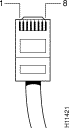
Note: Pins that are not used should not be connected.
E&M Pinouts
| Two-Wire Operation, Type | Four-Wire Operation, Type | |||||||||
| Pin | Signal | Description | 1 | 2 | 3 | 5 | 1 | 2 | 3 | 5 |
| 1 | SB | -48V signaling battery | – | SB | SB | – | – | SB | SB | – |
| 2 | M-lead | Signaling input | M | M | M | M | M | M | M | M |
| 3 | R | Ring, audio input | – | – | – | – | R | R | R | R |
| 4 | R or R1 | Ring, audio input/output or output | R | R | R | R | R1 | R1 | R1 | R1 |
| 5 | T or T1 | Tip, audio input/output or output | T | T | T | T | T1 | T1 | T1 | T1 |
| 6 | T | Tip, audio input | – | – | – | – | T | T | T | T |
| 7 | E-lead | Signaling output | E | E | E | E | E | E | E | E |
| 8 | SG | Signaling ground return | – | SG | SG | – | – | SG | SG | – |
Note: The Nortel Option11C PBX E&M Type I signaling matches the Cisco 3640 (or any other Cisco IOS gateway) Type V signaling. For more information about the Nortel PBX and Cisco Gateway Configuration, refer to Cisco 3640 Series Gateway-PBX Interoperability: Nortel Meridian 1 Option 11C PBX with Analog E&M Signaling.
Related Information
- Analog E&M Signaling Overview
- Understanding and Troubleshooting Analog E&M Interface Types and Wiring Arrangements
- Understanding and Troubleshooting Analog E&M Start Dial Supervision Signaling
- Cisco 3640 Series Gateway-PBX Interoperability: Nortel Meridian 1 Option 11C PBX with Analog E&M Signaling
- Understanding Voice Network Modules
- Understanding E&M Voice Interface Cards
- Voice Technology Support
- Voice and IP Communications Product Support
- Troubleshooting Cisco IP Telephony

- Technical Support - Cisco Systems
 Feedback