Specifications for Ethernet 100BaseTX and 10BaseT Cables
Available Languages
Contents
Introduction
This document provides guidelines and specifications for Ethernet 100BaseTX and 10BaseT cables.
Prerequisites
Requirements
There are no specific requirements for this document.
Components Used
The information in this document is based on the software and hardware versions:
-
Ethernet 100BaseTX and 10BaseT cables
The information in this document was created from the devices in a specific lab environment. All of the devices used in this document started with a cleared (default) configuration. If your network is live, make sure that you understand the potential impact of any command.
Conventions
Refer to Cisco Technical Tips Conventions for more information on document conventions.
Which Cable Do I Need?
The table below helps you determine which type of cable you need for your setup.
| Hub | Switch | Router | Workstation | |
|---|---|---|---|---|
| Hub | Crossover | Crossover | Straight | Straight |
| Switch | Crossover | Crossover | Straight | Straight |
| Router | Straight | Straight | Crossover | Crossover |
| Workstation | Straight | Straight | Crossover | Crossover |
Ethernet Cabling Guidelines
The table below lists the Ethernet cabling guidelines for 10BaseT and 100BaseTX cables.
| Specifications | 10BaseT | 100BaseTX |
|---|---|---|
| Maximum number of segments per network | 5 |
|
| Maximum hop count1 | 4 |
|
| Maximum number of nodes per segment | 1024 | 1024 |
| Cable type required | UTP, category 3, 4, or 5 | UTP category 5 or Shielded twisted pair (STP) |
1Hop count = Routing metric used to measure the distance between a source and a destination.
Ethernet Version 2 and IEEE 802.3 Physical Characteristics
The table below lists the Ethernet version 2 and IEEE 802.3 physical characteristics of the different Ethernet cables.
| Ethernet | IEEE 802.3 | |||
|---|---|---|---|---|
| 10Base5 | 10Base2 | 10BaseT | ||
| Data rate (Mbps) | 10 | 10 | 10 | 10 |
| Signaling method | Baseband | Baseband | Baseband | Baseband |
| Maximum segment length (m) | 500 | 500 | 185 | 100 (Unshielded twisted pair - UTP) |
| Media | 50-ohm coax (thick) | 50-ohm coax (thick) | 50-ohm coax (thin) | Unshielded twisted pair (UTP) |
| Topology | Bus | Bus | Bus | Star |
Fast Ethernet Connector Pinouts RJ-45
100BaseTX RJ-45 Connector
The Fast Ethernet RJ-45 port actively terminates wire pair 4 and 5 and wire pair 7 and 8. Common-mode termination reduces electromagnetic interference (EMI) and susceptibility to common-mode sources.
The table below shows the pin and corresponding signal for the RJ-45 connector pinouts.
| RJ-45 Connector Pinout | |
|---|---|
| Pin | Signal |
| 1 | TX+ |
| 2 | TX- |
| 3 | RX+ |
| 6 | RX- |
Specifications and Connection Limits for 100-Mbps Transmission
The table below lists cable specifications and connection limits for 100-Mbps transmission.
| Parameter | RJ-45 | MII | SC-type |
|---|---|---|---|
| Cable specification | Category 52, UTP3, 22 to 24 AWG4 | Category 3, r, or 5, 150-ohm UTP or STP, or multimode optical fiber | 62.5/125 multimode optical fiber |
| Maximum cable length | - | 0.5 m (1.64 ft.) (MII-to-MII cable5) | - |
| Maximum segment length | 100m (328 ft.) for 100BaseTX | 1 m (3.28 ft.)6 or 400 m (1312 ft.) for 100BaseFX | 100 m (328 ft.) |
| Maximum network length | 200 m (656 ft.)6 (with one repeater) | - | 200 m (656 ft.)6 (with one repeater) |
2 EIA/TIA-568 or EIA-TIA-568 TSB-36 compliant.
3 Cisco Systems does not supply Category 5 UTP RJ-45 or 150-ohm STP MII cables. Both are available commercially.
4 AWG = American Wire Gauge. This gauge is specified by the EIA/TIA-568 standard.
5 This is the cable between the MII port on the port adapter and the appropriate transceiver.
6 This length is specifically between any two stations on a repeated segment.
IEEE 802.3u Physical Characteristics
The table below lists the IEEE 802.3u physical characteristics for the Ethernet 100BaseT cable.
| Parameter | 100BaseT |
|---|---|
| Data rate (Mbps) | 100 |
| Signaling method | Baseband |
| Maximum segment length (in meters) | 100 m between DTE7 and repeaters |
| Media | RJ-45: Category 5 UTP MII: Category 3, 4, or 5, 150-ohm UTP or STP, with appropriate transceiver |
| Topology | Star/Hub |
7 DTE = data terminal equipment.
Ethernet 10BaseT: RJ-45
This section discusses the cable specifications for the 10-Mbps 10BaseT cable, and describes the different 10BaseT port pinouts.
Cable Specifications for 10-Mbps 10BaseT
The table below lists for cable specifications for the 10-Mbps 10BaseT cable.
| Parameter | RJ-45 |
|---|---|
| Cable specificataion | Category 3 or Category 5 UTP with 22 to 24 AWG |
| Maximum segment length | 100 m (328 ft.) for 10BaseT |
| Maximum network length | 2,800 m (9,186 ft.) (with four repeaters) |
10BaseT Port Pinouts
The table below lists the 10BaseT port pinouts.
| 8 pin8 | Description |
|---|---|
| 1 | TX+ |
| 2 | TX- |
| 3 | RX+ |
| 6 | RX- |
8Pins 4, 5, 7, and 8 are not used.
Straight-Through 10BaseT Cable (RJ-45 to RJ-45)
The table below lists the port pinouts for the straight-through 10BaseT cable.
| RJ-45 Pin | Signal | Direction | RJ-45 Pin |
|---|---|---|---|
| 1 | TX+ | ---> | 1 |
| 2 | TX- | ---> | 2 |
| 3 | RX+ | <--- | 3 |
| 4 | - | - | 4 |
| 5 | - | - | 5 |
| 6 | RX- | <--- | 6 |
| 7 | - | - | 7 |
| 8 | - | - | 8 |
Examine the sequence of colored wires to determine the type of RJ-45 cable, as follows:
-
Straight-through - the colored wires are in the same sequence at both ends of the cable.
-
Crossover - the first (far left) colored wire at one end of the cable is the third colored wire at the other end of the cable.
-
Rolled - the colored wires at one end of the cable are in the reverse sequence of the colored wires at the other end of the cable.
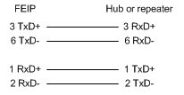
RJ-45 Straight-Through (Ethernet) Cable Pinouts
The table below lists the cable pinouts for the Ethernet RJ-45 straight-through cable.
| Signal | Pin | Pin | Signal |
|---|---|---|---|
| TX+ | 1 | 1 | TX+ |
| TX- | 2 | 2 | TX- |
| RX+ | 3 | 3 | RX+ |
| - | 4 | 4 | - |
| - | 5 | 5 | - |
| RX- | 6 | 6 | RX- |
| - | 7 | 7 | - |
| - | 8 | 8 | - |
RJ-45 Crossover (Ethernet) Cable Pinouts
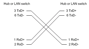
The table below lists the pinouts for the Ethernet RJ-45 crossover cable.
| Signal | Pin | Pin | Signal |
|---|---|---|---|
| TX+ | 1 | 3 | RX+ |
| TX- | 2 | 6 | RX- |
| RX+ | 3 | 1 | TX+ |
| - | 4 | 4 | - |
| - | 5 | 5 | - |
| RX- | 6 | 2 | TX- |
| - | 7 | 7 | - |
| - | 8 | 8 | - |
RJ-45 Rolled (Console) Cable Pinouts
The table below shows the pinouts for the RJ-45 rolled console cable.
| Signal | Pin | Pin | Signal |
|---|---|---|---|
| RTS | 1 | 8 | CTS |
| DTR | 2 | 7 | DSR |
| TxD | 3 | 6 | RxD |
| GND | 4 | 5 | GND |
| GND | 5 | 4 | GND |
| RxD | 6 | 3 | TxD |
| DSR | 7 | 2 | DTR |
| CTS | 8 | 1 | RTS |
Related Information
Revision History
| Revision | Publish Date | Comments |
|---|---|---|
1.0 |
01-Aug-2006
|
Initial Release |
 Feedback
Contact Cisco
- Open a Support Case

- (Requires a Cisco Service Contract)