Cisco Aironet 2.4-GHz/5-GHz 8-dBi Directional Antenna (AIR-ANT2588P3M-N)
Available Languages
Table of Contents
Cisco Aironet 2.4-GHz/5-GHz 8-dBi Directional Antenna (AIR-ANT2588P3M-N)
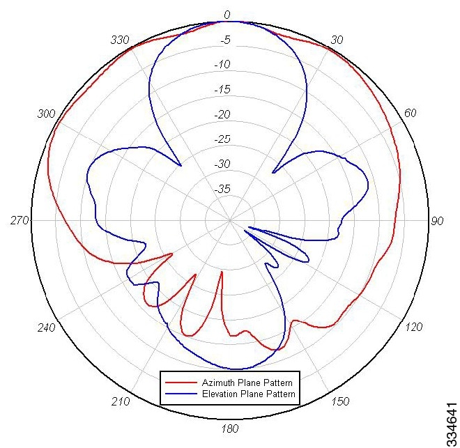
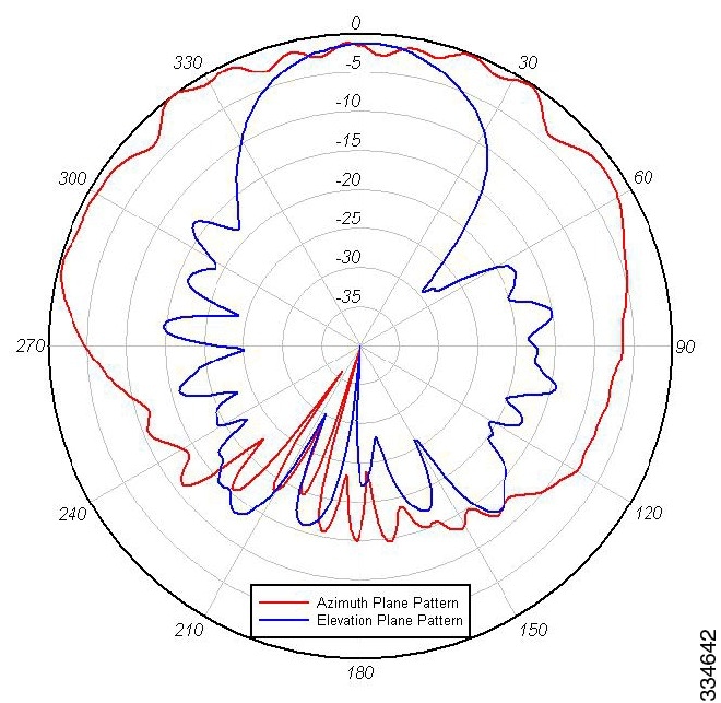
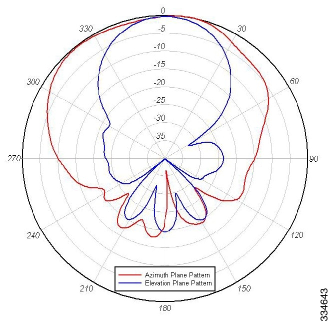
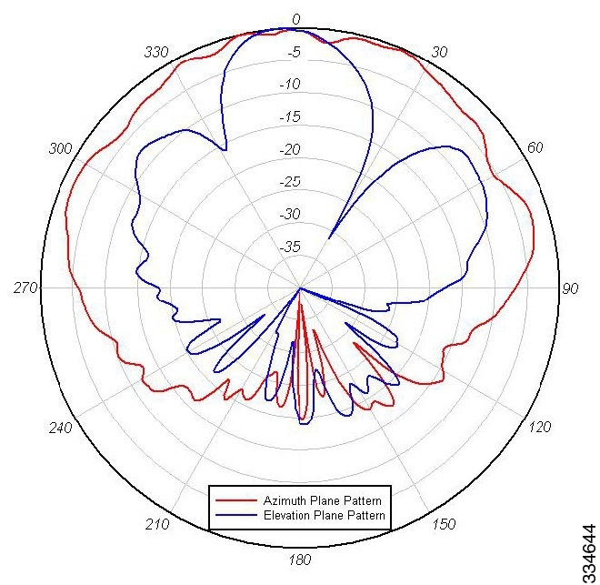
Azimuth and Elevation Radiation Patterns
Mounting on a Vertical Surface
Communications, Services, and Additional Information
Cisco Aironet 2.4-GHz/5-GHz 8-dBi Directional Antenna (AIR-ANT2588P3M-N)
This describes the Cisco Aironet AIR-ANT2588P3M-N 2.4/5-GHz 8-dBi 3-port directional antenna with N-connectors, and provides specifications and mounting instructions. The antenna operates in both the 2.4 GHz and 5 GHz frequency bands and is designed for outdoor use.
■
Azimuth and Elevation Radiation Patterns
System Requirements
This antenna is designed for outdoor use with any Cisco Aironet access point that requires three (3) dual-band antennas.
Safety Precautions
Translated versions of the following safety warnings are provided in the Safety Warnings for Cisco Aironet Antennas, which is available at http://www.cisco.com.
Warning: Installation of this antenna near power lines is dangerous. For your safety, follow the installation directions.
Warning: This warning symbol means danger. You are in a situation that could cause bodily injury. Before you work on any equipment, be aware of the hazards involved with electrical circuitry and be familiar with standard practices for preventing accidents.
Warning: In order to comply with international radio frequency (RF) exposure limits, dish antennas should be located at a minimum of 8.7 inches (22 cm) or more from the bodies of all persons. Other antennas should be located a minimum of 7.9 inches (20 cm) or more from the bodies of all persons.
Warning: Do not work on the system or connect or disconnect cables during periods of lightning activity.
Warning: This equipment must be grounded. Never defeat the ground conductor or operate the equipment in the absence of a suitably installed ground conductor. Contact the appropriate electrical inspection authority or an electrician if you are uncertain that suitable grounding is available.
Warning: Do not locate the antenna near overhead power lines or other electric light or power circuits, or where it can come into contact with such circuits. When installing the antenna, take extreme care not to come into contact with such circuits, as they may cause serious injury or death. For proper installation and grounding of the antenna, please refer to national and local codes (e.g. U.S.:NFPA 70, National Electrical Code, Article 810, in Canada: Canadian Electrical Code, Section 54).
Each year hundreds of people are killed or injured when attempting to install an antenna. In many of these cases, the victim was aware of the danger of electrocution but did not take adequate steps to avoid the hazard.
For your safety, and to help you achieve a good installation, please read and follow these safety precautions. They may save your life!
1.
2.
3.
4.
5.
b.
c.
6.
7.
8.
Installation Guidelines
Because the antennas transmit and receive radio signals, they are susceptible to RF obstructions and common sources of interference that can reduce throughput and range of the device to which they are connected. Follow these guidelines to ensure the best possible performance:
■
■
■
–
–
–
–
–
■
Site Selection
Before attempting to install your antenna, determine where you can best place the antenna for safety and performance.
To determine a safe distance from wires, power lines, and trees:
1.
2.
Caution: If you are unable to maintain this safe distance, stop and get professional help.
Generally, the higher an antenna is above the ground, the better it performs. Good practice is to install your antenna about 5 to 10 ft (1.5 to 3 m) above the roof line and away from all power lines and obstructions. If possible, find a mounting place directly above your wireless device so that the lead-in cable can be as short as possible.
Installing the Antenna
You can install the antenna on a pole from 1.63" to 2.3" pipe O.D. The mounting options allow the antenna to be vertically or horizontally polarized.
Tools and Equipment Required
■
The following tools and equipment are not provided:
■
Mounting on a Pole
To mount your antenna on a pole:
1.
2.
Figure 1 Attaching Antenna Mount Bracket
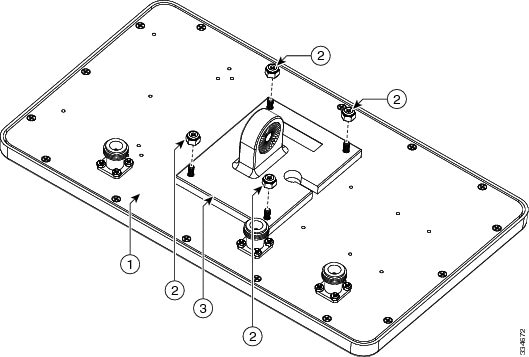
3.
Figure 2 Attach elevation adjustable bracket
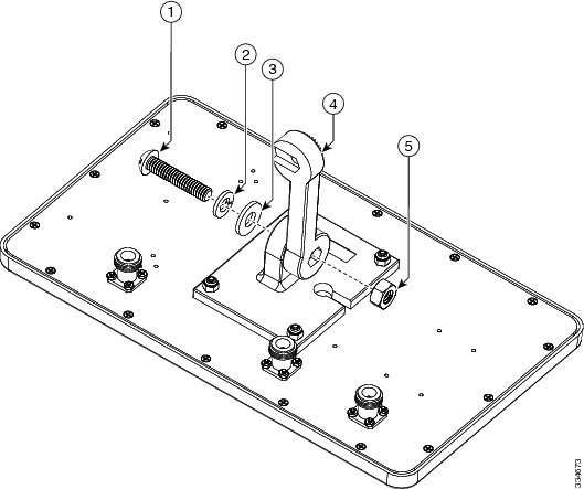
4.
Figure 3 Attaching Azimuth Adjustable Bracket
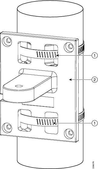
5.
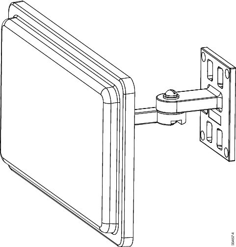
Figure 4 Attaching Antenna Assembly
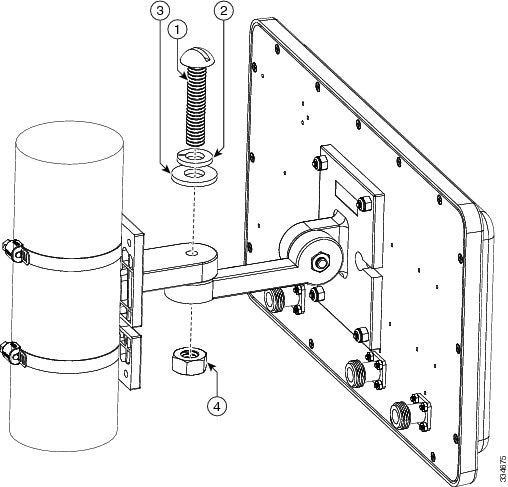
6.
Note: Cisco recommends grounding the antenna. See Grounding the Antenna.
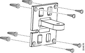
Mounting on a Vertical Surface
The antenna can be wall mounted. Hardware is not included for wall-mount installation.
To mount your antenna on a vertical surface:
1.
2.
3.
4.
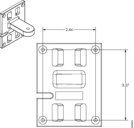
Distance Between Bracket Mounting Holes shows, in inches, the distance between the bracket mounting holes.
Figure 6 Distance Between Bracket Mounting Holes
5.
6.
Note: Cisco recommends grounding the antenna. See Grounding the Antenna.
Antenna Cable Information
The antenna is to be used with the Cisco 1552E access point. The port-to-port designations are as follows: port A of the antenna must be connected to port 4 of the access point, port B of the antenna must be connected to port 6 of the access point, and port C of the antenna must be connected to port 5 of the access point.
Note: Coaxial cable loses efficiency as the frequency increases, resulting in signal loss. The cable should be kept as short as possible, because cable length also determines the amount of signal loss (the longer the run, the greater the loss).
Cisco offers low-loss 5 ft. and 10 ft. coaxial cables, parts AIR-CAB005LL-N and AIR-CAB010LL-N, respectively, for connection from the antenna to the access point. These cables have one straight male type-N connector and one right angle male type-N connector. To use all of the ports on the AIR-ANT2588P3M-N three cables will be needed.
After the cable is attached to the antenna, make sure that the connections are sealed (if outdoors) to prevent moisture and other weathering elements from affecting performance. Cisco recommends using a coax seal (such as CoaxSeal) for outdoor connections. Silicone sealant or electrical tape are not recommended for sealing outdoor connections.
Grounding the Antenna
Follow these steps to ground the antenna in accordance with national electrical code instructions.
1.
2.
3.
4.
Caution: There may be wires in the wall. Ensure that your drilling location is clear of obstruction or other hazards.
5.
6.
Communications, Services, and Additional Information
■
■
■
■
■
■
Cisco Bug Search Tool
Cisco Bug Search Tool (BST) is a web-based tool that acts as a gateway to the Cisco bug tracking system that maintains a comprehensive list of defects and vulnerabilities in Cisco products and software. BST provides you with detailed defect information about your products and software.
THE SPECIFICATIONS AND INFORMATION REGARDING THE PRODUCTS IN THIS MANUAL ARE SUBJECT TO CHANGE WITHOUT NOTICE. ALL STATEMENTS, INFORMATION, AND RECOMMENDATIONS IN THIS MANUAL ARE BELIEVED TO BE ACCURATE BUT ARE PRESENTED WITHOUT WARRANTY OF ANY KIND, EXPRESS OR IMPLIED. USERS MUST TAKE FULL RESPONSIBILITY FOR THEIR APPLICATION OF ANY PRODUCTS.
THE SOFTWARE LICENSE AND LIMITED WARRANTY FOR THE ACCOMPANYING PRODUCT ARE INCORPORATED HEREIN BY THIS REFERENCE. IF YOU ARE UNABLE TO LOCATE THE SOFTWARE LICENSE OR LIMITED WARRANTY, CONTACT YOUR CISCO REPRESENTATIVE FOR A COPY.
The following information is for FCC compliance of Class A devices: This equipment has been tested and found to comply with the limits for a Class A digital device, pursuant to part 15 of the FCC rules. These limits are designed to provide reasonable protection against harmful interference when the equipment is operated in a commercial environment. This equipment generates, uses, and can radiate radio-frequency energy and, if not installed and used in accordance with the instruction manual, may cause harmful interference to radio communications. Operation of this equipment in a residential area is likely to cause harmful interference, in which case users will be required to correct the interference at their own expense.
The following information is for FCC compliance of Class B devices: This equipment has been tested and found to comply with the limits for a Class B digital device, pursuant to part 15 of the FCC rules. These limits are designed to provide reasonable protection against harmful interference in a residential installation. This equipment generates, uses and can radiate radio frequency energy and, if not installed and used in accordance with the instructions, may cause harmful interference to radio communications. However, there is no guarantee that interference will not occur in a particular installation. If the equipment causes interference to radio or television reception, which can be determined by turning the equipment off and on, users are encouraged to try to correct the interference by using one or more of the following measures:
■
■
■
■
Modifications to this product not authorized by Cisco could void the FCC approval and negate your authority to operate the product.
The Cisco implementation of TCP header compression is an adaptation of a program developed by the University of California, Berkeley (UCB) as part of UCB’s public domain version of the UNIX operating system. All rights reserved. Copyright © 1981, Regents of the University of California.
NOTWITHSTANDING ANY OTHER WARRANTY HEREIN, ALL DOCUMENT FILES AND SOFTWARE OF THESE SUPPLIERS ARE PROVIDED “AS IS” WITH ALL FAULTS. CISCO AND THE ABOVE-NAMED SUPPLIERS DISCLAIM ALL WARRANTIES, EXPRESSED OR IMPLIED, INCLUDING, WITHOUT LIMITATION, THOSE OF MERCHANTABILITY, FITNESS FOR A PARTICULAR PURPOSE AND NONINFRINGEMENT OR ARISING FROM A COURSE OF DEALING, USAGE, OR TRADE PRACTICE.
IN NO EVENT SHALL CISCO OR ITS SUPPLIERS BE LIABLE FOR ANY INDIRECT, SPECIAL, CONSEQUENTIAL, OR INCIDENTAL DAMAGES, INCLUDING, WITHOUT LIMITATION, LOST PROFITS OR LOSS OR DAMAGE TO DATA ARISING OUT OF THE USE OR INABILITY TO USE THIS MANUAL, EVEN IF CISCO OR ITS SUPPLIERS HAVE BEEN ADVISED OF THE POSSIBILITY OF SUCH DAMAGES.
Any Internet Protocol (IP) addresses and phone numbers used in this document are not intended to be actual addresses and phone numbers. Any examples, command display output, network topology diagrams, and other figures included in the document are shown for illustrative purposes only. Any use of actual IP addresses or phone numbers in illustrative content is unintentional and coincidental.
All printed copies and duplicate soft copies of this document are considered uncontrolled. See the current online version for the latest version.
Cisco has more than 200 offices worldwide. Addresses, phone numbers, and fax numbers are listed on the Cisco website at www.cisco.com/go/offices.
 Feedback
Contact Cisco
- Open a Support Case

- (Requires a Cisco Service Contract)