Switch Installation (8- and 12-Port Switches)
This chapter describes how to start your switch installation, including how to interpret the power-on self-test (POST) that ensures proper operation. It also describes how to install the switch.

Note ![]() This chapter describes the installation information specific to the Catalyst 3560-8PC and Catalyst 3560-12PC-S switches. For installing the other Catalyst 3560 switches, see Chapter 2 "Switch Installation (24- and 48-Port Switches)."
This chapter describes the installation information specific to the Catalyst 3560-8PC and Catalyst 3560-12PC-S switches. For installing the other Catalyst 3560 switches, see Chapter 2 "Switch Installation (24- and 48-Port Switches)."
Read the topics and perform the procedures in this order:
For information about connecting to the switch, see the "Connecting the Switch to Compatible Devices" section
Preparing for Installation
Warnings
These warnings are translated into several languages in the Regulatory Compliance and Safety Information for the Catalyst 3560 Switch.
 |
Warning |
|
Warning |
|
Warning |
|
Warning PWR-RPS2300 / PWR675-AC-RPS-N1 Statement 370 |
|
Warning |
|
Warning |
|
Warning |
|
Warning |
|
Warning |
|
Warning |
|
Warning |
|
Warning |
|
Warning |
|
Warning |
|
Warning |
|
Warning |
|
Warning |
|
Warning |
|
Warning |
|
Warning |
|
Warning |
|
Warning |
Statement 371—Power Cable and AC Adapter


Note ![]() The grounding architecture of this product is DC-isolated (DC-I).
The grounding architecture of this product is DC-isolated (DC-I).
Installation Guidelines
When you determine where to place the switch, be sure to observe these requirements:
•![]() The operating environment is within the ranges listed in "Technical Specifications."
The operating environment is within the ranges listed in "Technical Specifications."
•![]() Airflow around the switch and through the vents is unrestricted. Allow at least 3 inches (7.6 cm) of clearance on all sides and ventilation openings, particularly if you stack the switches or place them side by side.
Airflow around the switch and through the vents is unrestricted. Allow at least 3 inches (7.6 cm) of clearance on all sides and ventilation openings, particularly if you stack the switches or place them side by side.
•![]() You have allowed at least 1.75 inches (4 cm) of clearance above each switch in the rack.
You have allowed at least 1.75 inches (4 cm) of clearance above each switch in the rack.
•![]() Clearance to front and rear panels is such that
Clearance to front and rear panels is such that
–![]() You can easily read the front-panel indicators.
You can easily read the front-panel indicators.
–![]() Access to ports is sufficient for unrestricted cabling.
Access to ports is sufficient for unrestricted cabling.
–![]() The rear-panel power connector is within reach of an AC power receptacle.
The rear-panel power connector is within reach of an AC power receptacle.
•![]() Temperature around the unit does not exceed 113°F (45°C).
Temperature around the unit does not exceed 113°F (45°C).
If the switch is installed in a closed environment or in a multirack assembly, the temperature around it might be greater than normal room temperature.
•![]() The heat sinks and the bottom of the switch might be hot to the touch if the switch is operating at its maximum temperature 113°F (45°C) and is in an environment that exceeds normal room temperature (such as in a closet, in a cabinet, or in a closed or multirack assembly).
The heat sinks and the bottom of the switch might be hot to the touch if the switch is operating at its maximum temperature 113°F (45°C) and is in an environment that exceeds normal room temperature (such as in a closet, in a cabinet, or in a closed or multirack assembly).
•![]() No other items are placed on the top of the switch.
No other items are placed on the top of the switch.
•![]() The switch is not wall-mounted with its front panel facing up or sideways. According to safety regulations, wall-mount the switch with its front panel facing down to prevent airflow restriction and to provide easier access to the cables.
The switch is not wall-mounted with its front panel facing up or sideways. According to safety regulations, wall-mount the switch with its front panel facing down to prevent airflow restriction and to provide easier access to the cables.
•![]() Cabling is away from sources of electrical noise, such as radios, power lines, and fluorescent lighting fixtures. Make sure the cabling is safely away from other devices that might damage the cables.
Cabling is away from sources of electrical noise, such as radios, power lines, and fluorescent lighting fixtures. Make sure the cabling is safely away from other devices that might damage the cables.
•![]() For copper Ethernet ports, including 10/100 ports, 10/100/1000 ports, and 1000BASE-T SFP module ports, cable lengths from the switch to connected devices can be up to 328 feet (100 meters).
For copper Ethernet ports, including 10/100 ports, 10/100/1000 ports, and 1000BASE-T SFP module ports, cable lengths from the switch to connected devices can be up to 328 feet (100 meters).
•![]() The cables meet the specifications in Table B-1, which lists the cable specifications for 1000BASE-X and 100BASE-X SFP modules for the Catalyst 3560 switch. Catalyst 3560 switch SFP ports use both GLC-GE-100XX and GLC-FE-100XX SFP modules.
The cables meet the specifications in Table B-1, which lists the cable specifications for 1000BASE-X and 100BASE-X SFP modules for the Catalyst 3560 switch. Catalyst 3560 switch SFP ports use both GLC-GE-100XX and GLC-FE-100XX SFP modules.
When you use shorter lengths of single-mode fiber cable, you might need to insert an inline optical attenuator in the link to avoid overloading the receiver.
When the fiber-optic cable span is less than 15.43 miles (25 km), you should insert a 5-decibel (dB) or 10-dB inline optical attenuator between the fiber-optic cable plant and the receiving port on the 1000BASE-ZX SFP module at each end of the link.
•![]() Cisco Ethernet Switches are equipped with cooling mechanisms, such as fans and blowers. However, these fans and blowers can draw dust and other particles, causing contaminant buildup inside the chassis, which can result in a system malfunction.
Cisco Ethernet Switches are equipped with cooling mechanisms, such as fans and blowers. However, these fans and blowers can draw dust and other particles, causing contaminant buildup inside the chassis, which can result in a system malfunction.
You must install this equipment in an environment as free as possible from dust and foreign conductive material (such as metal flakes from construction activities).
These standards provide guidelines for acceptable working environments and acceptable levels of suspended particulate matter:
–![]() Network Equipment Building Systems (NEBS) GR-63-CORE
Network Equipment Building Systems (NEBS) GR-63-CORE
–![]() National Electrical Manufacturers Association (NEMA) Type 1
National Electrical Manufacturers Association (NEMA) Type 1
–![]() International Electrotechnical Commission (IEC) IP-20
International Electrotechnical Commission (IEC) IP-20
This applies to all Cisco Ethernet switches except for this compact model:
–![]() Catalyst 3560-8PC switch—8 10/100 PoE ports and 1 dual-purpose port (one 10/100/1000BASE-T copper port and one SFP module slot)
Catalyst 3560-8PC switch—8 10/100 PoE ports and 1 dual-purpose port (one 10/100/1000BASE-T copper port and one SFP module slot)
Equipment That You Supply
You need this equipment to install the switch:
•![]() Number-2 Phillips screwdriver
Number-2 Phillips screwdriver
•![]() Drill with a #27 drill bit (0.144-inch [3.7 mm])
Drill with a #27 drill bit (0.144-inch [3.7 mm])
You can order an optional cable guard to secure cables to the front of the switch and to prevent accidental removal. To order a cable guard (CBLGRD-C3560-12PC or CBLGRD-C3560-8PC), contact your Cisco representative.
The switch has security slots in the left and right side panels. You can install an optional cable lock, such as the type that is used to secure a laptop, to secure either or both sides of the switch. Cable locks are available from most computer accessory suppliers.
Installing the switch in a 19-inch rack requires an optional bracket kit that is not included but which you can order, RCKMNT-19-CMPCT=.
If you want to connect a terminal to the switch console port, you need to provide an RJ-45-to-DB-25 female DTE adapter. You can order a kit (part number ACS-DSBUASYN=) with that adapter from Cisco.
Box Contents
The switch getting started guide on Cisco.com describes the box contents. If any item is missing or damaged, contact your Cisco representative or reseller for support.
Tools and Equipment
You need to supply a number-2 Phillips screwdriver to rack-mount the switch.
Verifying Switch Operation
Before you install the switch, power it on and verify that it passes POST. See the getting started guide for the steps required to connect a PC to the switch and to run Express Setup. To power on the switch, connect one end of the AC power cord to the AC power connector on the switch, and connect the other end of the power cord to an AC power outlet.
When the switch powers on, it automatically begins the POST, a series of tests that verifies that the switch functions properly. When the switch begins POST, the system LED slowly blinks green. When POST completes, the system LED blinks amber. If POST fails, the system LED remains amber. If POST completes successfully, the system LED rapidly blinks green.
Call Cisco technical support representative if your switch fails POST.
Powering Off the Switch
After a successful POST, disconnect the power cord from the switch. Install the switch in a rack, on a wall, on a table, or on a shelf as described in the "Installing the Switch" section.
Installing the Switch
•![]() Wall-Mounting (with Mounting Screws)
Wall-Mounting (with Mounting Screws)
•![]() Wall-Mounting (with Rack-Mount Brackets)
Wall-Mounting (with Rack-Mount Brackets)
Before installing the switch, review the "Installation Guidelines" section.
Desk or Shelf Mounting
•![]() Desk or Shelf Mounting (Unsecured)
Desk or Shelf Mounting (Unsecured)
•![]() Desk or Shelf Mounting (Secured)
Desk or Shelf Mounting (Secured)
•![]() Under the Desk or Shelf Mounting
Under the Desk or Shelf Mounting
Desk or Shelf Mounting (Unsecured)
Step 1 ![]() Locate the adhesive strip with the rubber feet in the accessory kit.
Locate the adhesive strip with the rubber feet in the accessory kit.
Step 2 ![]() Remove the four rubber feet from the adhesive strip, and attach them to the recessed areas on the bottom of the unit. They prevent the switch from sliding on the desk or shelf.
Remove the four rubber feet from the adhesive strip, and attach them to the recessed areas on the bottom of the unit. They prevent the switch from sliding on the desk or shelf.
Note ![]() We strongly recommend that you attach the rubber feet. Doing so improves airflow and reduces overheating.
We strongly recommend that you attach the rubber feet. Doing so improves airflow and reduces overheating.
Step 3 ![]() Place the switch on the desk or shelf.
Place the switch on the desk or shelf.
Desk or Shelf Mounting (Secured)
Step 1 ![]() Locate the screw template. The template is used to align the mounting screw holes and is also a guide for making sure that the screws have proper clearance.
Locate the screw template. The template is used to align the mounting screw holes and is also a guide for making sure that the screws have proper clearance.
Step 2 ![]() Position the screw template on top of the desk or shelf so that the two side-by-side slots face the front of the desk or shelf, as shown in Figure 3-1. This ensures that the power cord faces the rear of the desk or shelf after the switch is installed.
Position the screw template on top of the desk or shelf so that the two side-by-side slots face the front of the desk or shelf, as shown in Figure 3-1. This ensures that the power cord faces the rear of the desk or shelf after the switch is installed.
Note ![]() Wait before you attach the screw template to the desk or shelf.
Wait before you attach the screw template to the desk or shelf.
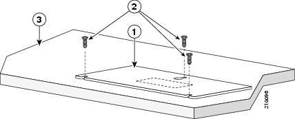
Figure 3-1 Installing the Mounting Screws on a Desk or Shelf
|
|
Screw template |
|
Desk or shelf |
|
|
Screws |
||
Step 3 ![]() Peel the adhesive strip off the bottom of the screw template, and attach it to the top of the desk or shelf.
Peel the adhesive strip off the bottom of the screw template, and attach it to the top of the desk or shelf.
Step 4 ![]() Use a 0.144-inch (3.7 mm) or a #27 drill bit to drill a 1/2-inch (12.7 mm) hole in the three screw template slots.
Use a 0.144-inch (3.7 mm) or a #27 drill bit to drill a 1/2-inch (12.7 mm) hole in the three screw template slots.
Step 5 ![]() Insert three screws in the slots on the screw template, and tighten until they touch the top of the screw template.
Insert three screws in the slots on the screw template, and tighten until they touch the top of the screw template.
Step 6 ![]() Remove the screw template from the desk or shelf.
Remove the screw template from the desk or shelf.
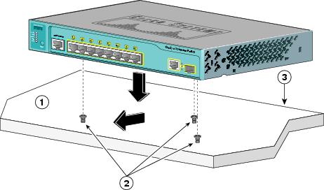
Step 7 ![]() Place the switch on the mounting screws, and slide it forward until it locks in place, as shown in Figure 3-2.
Place the switch on the mounting screws, and slide it forward until it locks in place, as shown in Figure 3-2.
Figure 3-2 Mounting the Switch on a Desk or Shelf With Mounting Screws
|
|
Slides on this way |
|
Desk or shelf |
|
|
Screws |
|
Wall |
Under the Desk or Shelf Mounting
Step 1 ![]() Locate the screw template. The template helps to align the mounting screw holes and is a guide to make sure the screws are installed under the desk or shelf with proper clearance.
Locate the screw template. The template helps to align the mounting screw holes and is a guide to make sure the screws are installed under the desk or shelf with proper clearance.
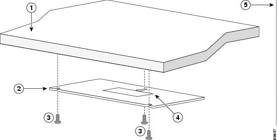
Step 2 ![]() Position the screw template underneath the desk or shelf so that the two side-by-side slots face the front of the desk or shelf, as shown in Figure 3-3. This ensures that the power cord faces the rear of the desk or shelf after the switch is installed. Wait before you attach the screw template to the desk or shelf.
Position the screw template underneath the desk or shelf so that the two side-by-side slots face the front of the desk or shelf, as shown in Figure 3-3. This ensures that the power cord faces the rear of the desk or shelf after the switch is installed. Wait before you attach the screw template to the desk or shelf.
Figure 3-3 Installing the Mounting Screws Under a Desk or Shelf
|
|
Desk or shelf |
|
Adhesive |
|
|
Screw template |
|
Wall |
|
|
Screws |
Step 3 ![]() Peel the adhesive strip off the bottom of the screw template, and attach it to the underside of the desk or shelf.
Peel the adhesive strip off the bottom of the screw template, and attach it to the underside of the desk or shelf.
Step 4 ![]() Use a 0.144-inch (3.7 mm) or a #27 drill bit to drill a 1/2 inch (12.7 mm) hole in the three screw template slots.
Use a 0.144-inch (3.7 mm) or a #27 drill bit to drill a 1/2 inch (12.7 mm) hole in the three screw template slots.
Step 5 ![]() Insert three screws in the slots on the screw template, and tighten until they touch the top of the screw template.
Insert three screws in the slots on the screw template, and tighten until they touch the top of the screw template.
Step 6 ![]() Remove the screw template from underneath the desk or shelf.
Remove the screw template from underneath the desk or shelf.
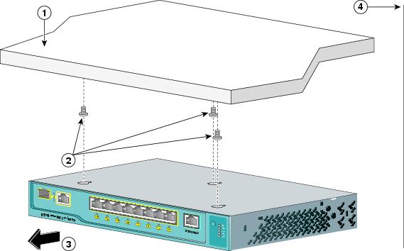
Step 7 ![]() Place the switch onto the mounting screws and slide the switch forward until it locks in place, as shown in Figure 3-4.
Place the switch onto the mounting screws and slide the switch forward until it locks in place, as shown in Figure 3-4.
Figure 3-4 Mounting the Switch Under a Desk or Shelf
|
|
Desk or shelf |
|
Slides on this way |
|
|
Screws |
|
Wall |
After the switch is mounted on or under the desk or shelf:
1. ![]() (Optional) Secure the AC power cord. See "Securing the AC Power Cord" section.
(Optional) Secure the AC power cord. See "Securing the AC Power Cord" section.
2. ![]() Power on the switch. See the "Verifying Switch Operation" section.
Power on the switch. See the "Verifying Switch Operation" section.
3. ![]() Connect to a 10/100 or 10/100/1000 port, and run Express Setup. See the Catalyst 3560 Switch Getting Started Guide for instructions. To use the CLI setup program, see "Configuring the Switch with the CLI-Based Setup Program."
Connect to a 10/100 or 10/100/1000 port, and run Express Setup. See the Catalyst 3560 Switch Getting Started Guide for instructions. To use the CLI setup program, see "Configuring the Switch with the CLI-Based Setup Program."
4. ![]() Connect to the front-panel ports.
Connect to the front-panel ports.
Wall-Mounting (with Mounting Screws)
Mount the switch with the front panel facing down (as shown in Figure 3-5 and Figure 3-6.)
|
Warning |
Step 1 ![]() Locate the screw template. The template is used to align the mounting screw holes.
Locate the screw template. The template is used to align the mounting screw holes.
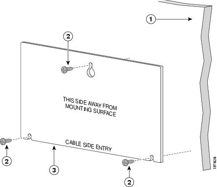
Step 2 ![]() Position the screw template so that the two side-by-side slots face toward the floor, as shown in Figure 3-5.
Position the screw template so that the two side-by-side slots face toward the floor, as shown in Figure 3-5.
For the best support of the switch and cables, make sure the switch is attached securely to a wall stud or to a firmly attached plywood mounting backboard.
Note ![]() Wait before you attach the screw template to the wall.
Wait before you attach the screw template to the wall.
Figure 3-5 Installing the Mounting Screws on a Wall
|
|
Wall |
|
Screw template |
|
|
Screws |
Step 3 ![]() Peel the adhesive strip off the bottom of the screw template.
Peel the adhesive strip off the bottom of the screw template.
Step 4 ![]() Attach the screw template to the wall.
Attach the screw template to the wall.
Step 5 ![]() Use a 0.144-inch (3.7 mm) or a #27 drill bit to drill a 1/2 inch (12.7 mm) hole in the three screw template slots.
Use a 0.144-inch (3.7 mm) or a #27 drill bit to drill a 1/2 inch (12.7 mm) hole in the three screw template slots.
Step 6 ![]() Insert three screws in the slots on the screw template, and tighten until they touch the top of the screw template.
Insert three screws in the slots on the screw template, and tighten until they touch the top of the screw template.
Step 7 ![]() Remove the screw template from the wall.
Remove the screw template from the wall.
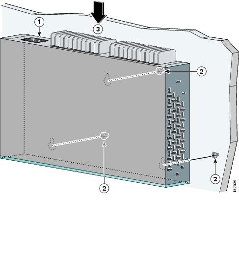
Step 8 ![]() Place the switch onto the mounting screws and slide it down until it locks in place, as shown in Figure 3-6.
Place the switch onto the mounting screws and slide it down until it locks in place, as shown in Figure 3-6.
Figure 3-6 Installing the Switch On a Wall
|
|
Switch |
|
Slides down |
|
|
Screw |
After the switch is mounted on the wall:
1. ![]() (Optional) Secure the AC power cord. See "Securing the AC Power Cord" section.
(Optional) Secure the AC power cord. See "Securing the AC Power Cord" section.
2. ![]() Power on the switch. See the "Verifying Switch Operation" section.
Power on the switch. See the "Verifying Switch Operation" section.
3. ![]() Connect to a 10/100 or 10/100/1000 port, and run Express Setup. See the Catalyst 3560 Switch Getting Started Guide for instructions. To use the CLI setup program, see "Configuring the Switch with the CLI-Based Setup Program."
Connect to a 10/100 or 10/100/1000 port, and run Express Setup. See the Catalyst 3560 Switch Getting Started Guide for instructions. To use the CLI setup program, see "Configuring the Switch with the CLI-Based Setup Program."
4. ![]() Connect to the front-panel ports.
Connect to the front-panel ports.
Magnet Mounting
|
Warning |
Step 1 ![]() Place one side of the magnet against the bottom of the switch, as shown in Figure 3-7.
Place one side of the magnet against the bottom of the switch, as shown in Figure 3-7.
Figure 3-7 Mounting the Switch with a Magnet
|
|
Metal mounting surface |
|
Switch front panel |
|
|
Mounting magnet |
Step 2 ![]() Mount the magnet and switch on a vertical metal surface.
Mount the magnet and switch on a vertical metal surface.
After the switch is attached to the mounting magnet:
1. ![]() (Optional) Secure the AC power cord. See "Securing the AC Power Cord" section.
(Optional) Secure the AC power cord. See "Securing the AC Power Cord" section.
2. ![]() Power on the switch. See the "Verifying Switch Operation" section.
Power on the switch. See the "Verifying Switch Operation" section.
3. ![]() Connect to a 10/100 or 10/100/1000 port, and run Express Setup. See the Catalyst 3560 Switch Getting Started Guide for instructions. To use the CLI setup program, see "Configuring the Switch with the CLI-Based Setup Program."
Connect to a 10/100 or 10/100/1000 port, and run Express Setup. See the Catalyst 3560 Switch Getting Started Guide for instructions. To use the CLI setup program, see "Configuring the Switch with the CLI-Based Setup Program."
4. ![]() Connect to the front-panel ports.
Connect to the front-panel ports.
Rack-Mounting
Installing the Catalyst 3560-8PC switch or the Catalyst 3560 12-PC-S switch in a 19-inch rack requires a bracket kit that is not included with the switch (RCKMNT-19-CMPCT=).
•![]() Attaching Brackets to the Switch
Attaching Brackets to the Switch
•![]() Mounting the Switch in a 19-Inch Rack
Mounting the Switch in a 19-Inch Rack
|
To prevent bodily injury when mounting or servicing this unit in a rack, you must take special precautions to ensure that the system remains stable. The following guidelines are provided to ensure your safety: • • •
|
Attaching Brackets to the Switch
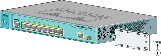
Figure 3-8 shows how to attach a 19-inch bracket to one side of the switch. Follow the same steps to attach the second bracket to the opposite side.
Figure 3-8 Attaching the 19-inch Brackets for Rack-Mounting
|
|
Phillips flat-head screws |
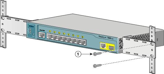
Mounting the Switch in a 19-Inch Rack
After the brackets are attached to the switch, insert the switch into the 19-inch rack, and align the bracket in the rack. Use either the 10-32 pan-head screws or the 12-24 pan-slotted screws to secure the switch in the rack, as shown in Figure 3-9.
Note ![]() We strongly recommend that you allow at least 1.75 inches (4 cm) of clearance above each switch in the rack.
We strongly recommend that you allow at least 1.75 inches (4 cm) of clearance above each switch in the rack.
Figure 3-9 Mounting the Switch in a 19-Inch Rack
|
|
Phillips machine screws |
After the switch is mounted in the rack:
1. ![]() (Optional) Secure the AC power cord. See "Securing the AC Power Cord" section.
(Optional) Secure the AC power cord. See "Securing the AC Power Cord" section.
2. ![]() Power on the switch. See the "Verifying Switch Operation" section.
Power on the switch. See the "Verifying Switch Operation" section.
3. ![]() Connect to a 10/100 or 10/100/1000 port, and run Express Setup. See the Catalyst 3560 Switch Getting Started Guide for instructions. To use the CLI setup program, see "Configuring the Switch with the CLI-Based Setup Program."
Connect to a 10/100 or 10/100/1000 port, and run Express Setup. See the Catalyst 3560 Switch Getting Started Guide for instructions. To use the CLI setup program, see "Configuring the Switch with the CLI-Based Setup Program."
4. ![]() Connect to the front-panel ports.
Connect to the front-panel ports.
Wall-Mounting (with Rack-Mount Brackets)
Installing the Catalyst 3560-8PC switch or the Catalyst 3560 12-PC-S switch in a 19-inch rack requires a bracket kit that is not included with the switch (RCKMNT-19-CMPCT=).
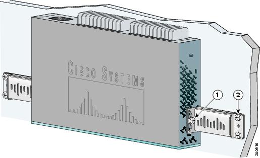
Step 1 ![]() Attach a 19-inch bracket to one side of the switch. Follow the same steps to attach the second bracket to the opposite side, as shown in Figure 3-10.
Attach a 19-inch bracket to one side of the switch. Follow the same steps to attach the second bracket to the opposite side, as shown in Figure 3-10.
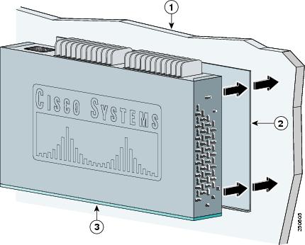
Step 2 ![]() Mount the switch with the front panel facing down, as shown in Figure 3-10.
Mount the switch with the front panel facing down, as shown in Figure 3-10.
For the best support of the switch and cables, make sure the switch is attached securely to wall studs or to a firmly attached plywood mounting backboard.
Do not wall-mount the switch with its front panel facing up or sideways. According to safety regulations, wall-mount the switch with its front panel facing down to prevent airflow restriction and to provide easier access to the cables.
Figure 3-10 Mounting the Switch on a Wall
|
|
Phillips flat-head screws |
|
User-supplied screws |
After the switch is mounted on the wall:
1. ![]() (Optional) Secure the AC power cord. See "Securing the AC Power Cord" section.
(Optional) Secure the AC power cord. See "Securing the AC Power Cord" section.
2. ![]() Power on the switch. See the "Verifying Switch Operation" section.
Power on the switch. See the "Verifying Switch Operation" section.
3. ![]() Connect to a 10/100 or 10/100/1000 port, and run Express Setup. See the Catalyst 3560 Switch Getting Started Guide for instructions. To use the CLI setup program, see "Configuring the Switch with the CLI-Based Setup Program."
Connect to a 10/100 or 10/100/1000 port, and run Express Setup. See the Catalyst 3560 Switch Getting Started Guide for instructions. To use the CLI setup program, see "Configuring the Switch with the CLI-Based Setup Program."
4. ![]() Connect to the front-panel ports.
Connect to the front-panel ports.
Securing the AC Power Cord
The AC power-cord retainer is an optional part (PWR-CLIP-CMP).
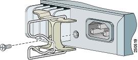
Step 1 ![]() Insert the power-cord retainer wire into the slot on the plastic holder.
Insert the power-cord retainer wire into the slot on the plastic holder.
Step 2 ![]() Attach the plastic holder onto the switch rear panel with the supplied screw (see Figure 3-11).
Attach the plastic holder onto the switch rear panel with the supplied screw (see Figure 3-11).
Figure 3-11 Insert the Power-Cord Retainer
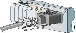
Step 3 ![]() Rotate the wire to the right side of the AC power cord connector, and insert the AC power cord (see Figure 3-12).
Rotate the wire to the right side of the AC power cord connector, and insert the AC power cord (see Figure 3-12).
Figure 3-12 Insert the AC Power Cord
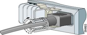
Step 4 ![]() Place the power cord bushing on the power cord with the opening at the top. The retainer wire only fits into one slot on the bushing. Move the retainer wire into the bushing slot (see Figure 3-13).
Place the power cord bushing on the power cord with the opening at the top. The retainer wire only fits into one slot on the bushing. Move the retainer wire into the bushing slot (see Figure 3-13).
Figure 3-13 Attach the Power-Cord Bushing
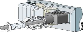
Step 5 ![]() Slide the bushing so that it rests against the power-cord connector, and then rotate the bushing clockwise until the bushing is securely fastened and its opening is on the right side of the power cord (see Figure 3-14).
Slide the bushing so that it rests against the power-cord connector, and then rotate the bushing clockwise until the bushing is securely fastened and its opening is on the right side of the power cord (see Figure 3-14).
Figure 3-14 Rotate the Bushing Clockwise
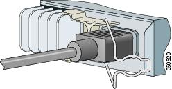
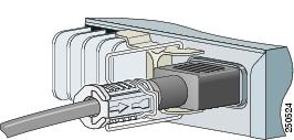
Step 6 ![]() Insert the securing clip in the opening of the bushing (see Figure 3-15).
Insert the securing clip in the opening of the bushing (see Figure 3-15).
Figure 3-15 Insert the Securing Clip
After the power cord is correctly secured, it looks like this:
Where to Go Next
If the default configuration is satisfactory, the switch does not need further configuration. You can use any of these management options to change the default configuration:
•![]() Start the device manager, which is in the switch memory, to manage individual switches. The device manager is a web interface that offers quick configuration and monitoring. You can access the device manager from anywhere in your network through a web browser. For more information, see the device manager online help.
Start the device manager, which is in the switch memory, to manage individual switches. The device manager is a web interface that offers quick configuration and monitoring. You can access the device manager from anywhere in your network through a web browser. For more information, see the device manager online help.
•![]() Start the Network Assistant application, which is described in the Getting Started with Cisco Network Assistant guide. Through this GUI, you can configure and monitor a switch cluster or an individual switch.
Start the Network Assistant application, which is described in the Getting Started with Cisco Network Assistant guide. Through this GUI, you can configure and monitor a switch cluster or an individual switch.
•![]() Use the CLI from the console to configure the switch as a member of a cluster or as an individual switch. See the Catalyst 3560 Switch Software Configuration Guide and the Catalyst 3560 Switch Command Reference on Cisco.com for information on using the CLI with a Catalyst 3560 switch.
Use the CLI from the console to configure the switch as a member of a cluster or as an individual switch. See the Catalyst 3560 Switch Software Configuration Guide and the Catalyst 3560 Switch Command Reference on Cisco.com for information on using the CLI with a Catalyst 3560 switch.
•![]() Start an SNMP application such as the CiscoView application.
Start an SNMP application such as the CiscoView application.
 Feedback