Connecting to DC Power
This appendix describes how to make DC power connections to the Catalyst 3560V2-24TS-SD switch. See "Switch Installation (24- and 48-Port Switches)" and "Switch Installation (8- and 12-Port Switches)" for instructions on installing the switch.
Connecting to DC Power
To connect the Catalyst 3560V2-24TS-SD switch to a DC-input power source, follow the steps in these sections:
•![]() Wiring the DC-Input Power Source
Wiring the DC-Input Power Source

Note ![]() We recommend that you use 18 AWG copper wiring for Network Equipment Building Systems (NEBS) installation. This guideline follows the standard guidelines for DC power wiring in the Central Office.
We recommend that you use 18 AWG copper wiring for Network Equipment Building Systems (NEBS) installation. This guideline follows the standard guidelines for DC power wiring in the Central Office.
Note ![]() When an RPS is connected to the Catalyst 3560V2-24TS-SD switch, the switch is not NEBS compliant.
When an RPS is connected to the Catalyst 3560V2-24TS-SD switch, the switch is not NEBS compliant.
Note ![]() The grounding architecture of this product is DC-isolated (DC-I).
The grounding architecture of this product is DC-isolated (DC-I).

Preparing for Installation
Locate the ground lug and the two number-10-32 screws on the switch rear panel and the DC terminal block plug in the DC-switch accessory kit.
Obtain these necessary tools and equipment:
•![]() Ratcheting torque screwdriver with a Phillips head that exerts up to 15 pound-force inches (lbf-in.) or 240 ounce-force inches (ozf-in.) of pressure
Ratcheting torque screwdriver with a Phillips head that exerts up to 15 pound-force inches (lbf-in.) or 240 ounce-force inches (ozf-in.) of pressure
•![]() Panduit crimping tool with optional controlled cycle mechanism (model CT-700, CT-720, CT-920, CT-920CH, CT-930, or CT-940CH)
Panduit crimping tool with optional controlled cycle mechanism (model CT-700, CT-720, CT-920, CT-920CH, CT-930, or CT-940CH)
•![]() 6-gauge copper ground wire (insulated or noninsulated)
6-gauge copper ground wire (insulated or noninsulated)
•![]() Four leads of 18-gauge copper wire
Four leads of 18-gauge copper wire
•![]() Wire-stripping tools for stripping 6- and 18-gauge wires
Wire-stripping tools for stripping 6- and 18-gauge wires
Grounding the Switch
To ground the switch to earth ground, follow these steps. Make sure to follow any grounding requirements at your site.
Step 1 ![]() Locate and remove the ground lug and the two number-10-32 ground-lug screws from the rear panel of the switch. (See Figure C-3 for location.) Use a standard Phillips screwdriver or a ratcheting torque screwdriver with a Phillips head. Set the screws and the ground lug aside.
Locate and remove the ground lug and the two number-10-32 ground-lug screws from the rear panel of the switch. (See Figure C-3 for location.) Use a standard Phillips screwdriver or a ratcheting torque screwdriver with a Phillips head. Set the screws and the ground lug aside.
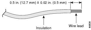
Step 2 ![]() If your ground wire is insulated, use a wire stripping tool to strip the 6-gauge ground wire to 0.5 inch (12.7 mm) ± 0.02 inch (0.5 mm), as shown in Figure C-1.
If your ground wire is insulated, use a wire stripping tool to strip the 6-gauge ground wire to 0.5 inch (12.7 mm) ± 0.02 inch (0.5 mm), as shown in Figure C-1.
Figure C-1 Stripping the Ground Wire
Step 3 ![]() Slide the open end of the ground lug over the exposed area of the 6-gauge wire.
Slide the open end of the ground lug over the exposed area of the 6-gauge wire.
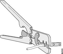
Step 4 ![]() Using a Panduit crimping tool, crimp the ground lug to the 6-gauge wire, as shown in Figure C-2.
Using a Panduit crimping tool, crimp the ground lug to the 6-gauge wire, as shown in Figure C-2.
Figure C-2 Crimping the Ground Lug
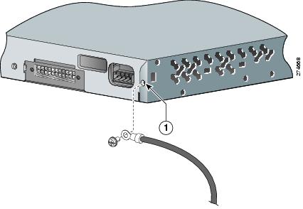
Step 5 ![]() Use the two number-10-32 screws to attach the ground lug and wire assembly to the switch rear panel ground connector, as shown in Figure C-3. If you are using an RPS, connect the ground lug as shown in Figure C-4.
Use the two number-10-32 screws to attach the ground lug and wire assembly to the switch rear panel ground connector, as shown in Figure C-3. If you are using an RPS, connect the ground lug as shown in Figure C-4.
Step 6 ![]() Using a ratcheting torque screwdriver, torque each ground-lug screw to 15 lbf-in. (240 ozf-in.)
Using a ratcheting torque screwdriver, torque each ground-lug screw to 15 lbf-in. (240 ozf-in.)
Figure C-3 Attaching the Ground Lug Assembly Over the RPS Connector
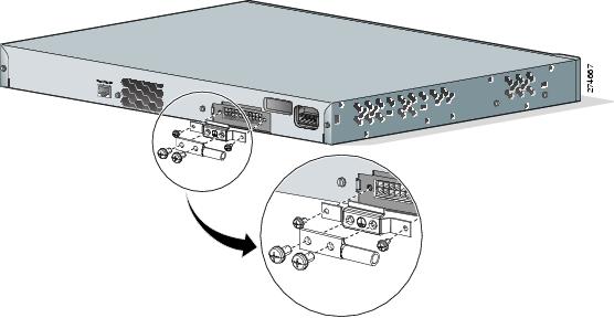
Figure C-4 Attaching the Ground Lug to the Ground Lug Hole
|
|
Ground hole location |
Wiring the DC-Input Power Source
 |
Warning |
|
Warning |
Note ![]() This installation must comply with all applicable codes.
This installation must comply with all applicable codes.
To wire the switch to a DC-input power source, follow these steps:
Step 1 ![]() Apply tape to the circuit-breaker switch handle, and move the circuit-breaker handle to the off position.
Apply tape to the circuit-breaker switch handle, and move the circuit-breaker handle to the off position.
Step 2 ![]() Locate and remove the terminal block plug (see Figure C-5).
Locate and remove the terminal block plug (see Figure C-5).
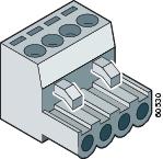
Figure C-5 Terminal Block Plug
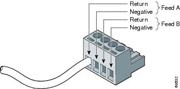
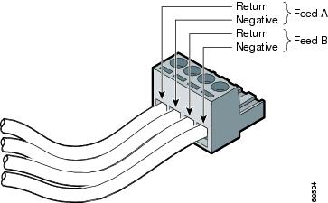
Step 3 ![]() Identify the positive and negative feed positions for the terminal block connection. The wiring sequence is positive to positive and negative to negative for both the A and the B feed wires. The switch rear panel identifies the positive and negative positions for both the A and B feed wires.
Identify the positive and negative feed positions for the terminal block connection. The wiring sequence is positive to positive and negative to negative for both the A and the B feed wires. The switch rear panel identifies the positive and negative positions for both the A and B feed wires.
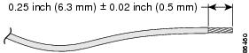
Step 4 ![]() Using a 18-gauge wire-stripping tool, strip each of the four wires coming from the DC-input power source to 0.27 inch (6.6 mm) ± 0.02 inch (0.5 mm), as shown in Figure C-6. Do not strip more than 0.29 inch (7.4 mm) of insulation from the wire. Stripping more than the recommended amount of wire can leave exposed wire from the terminal block plug after installation.
Using a 18-gauge wire-stripping tool, strip each of the four wires coming from the DC-input power source to 0.27 inch (6.6 mm) ± 0.02 inch (0.5 mm), as shown in Figure C-6. Do not strip more than 0.29 inch (7.4 mm) of insulation from the wire. Stripping more than the recommended amount of wire can leave exposed wire from the terminal block plug after installation.
Figure C-6 Stripping the DC-Input Power Source Wire
Step 5 ![]() Insert the exposed wire of one of the four DC-input power source wires into the terminal block plug, as shown in Figure C-7. Make sure that you cannot see any wire lead. Only wire with insulation should extend from the terminal block.
Insert the exposed wire of one of the four DC-input power source wires into the terminal block plug, as shown in Figure C-7. Make sure that you cannot see any wire lead. Only wire with insulation should extend from the terminal block.
Figure C-7 Inserting Wires in the Terminal Block Plug
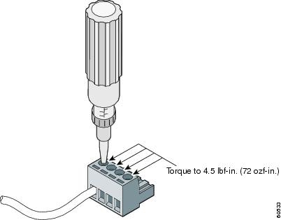
Step 6 ![]() Use a ratcheting torque screwdriver to torque the terminal block captive screw (above the installed wire lead) to 4.5 lbf-in. (72 ozf-in.), as shown in Figure C-8.
Use a ratcheting torque screwdriver to torque the terminal block captive screw (above the installed wire lead) to 4.5 lbf-in. (72 ozf-in.), as shown in Figure C-8.
Figure C-8 Torquing the Terminal-Block Captive Screws
Step 7 ![]() Repeat Steps 4 and 5 for the remaining three DC-input power source wires. Figure C-9 shows the completed wiring of a terminal block plug.
Repeat Steps 4 and 5 for the remaining three DC-input power source wires. Figure C-9 shows the completed wiring of a terminal block plug.
Figure C-9 Completed Wiring of Terminal Block Plug
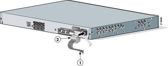
Step 8 ![]() Insert the terminal block plug in the terminal block header on the switch rear panel, as shown in Figure C-10.
Insert the terminal block plug in the terminal block header on the switch rear panel, as shown in Figure C-10.
Figure C-10 Inserting the Terminal Block in the Block Header
|
|
Tie wrap |
|
Terminal block |
Step 9 ![]() Remove the tape from the circuit-breaker switch handle, and move the circuit-breaker handle to the on position.
Remove the tape from the circuit-breaker switch handle, and move the circuit-breaker handle to the on position.
 Feedback