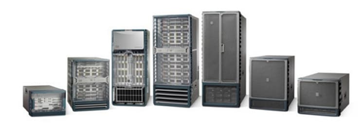
Cisco Nexus 7000 Series Switches
| Overview | Product Overview |
|---|---|
| Product Type | Data Center Switches |
| Status |
End of Sale
EOL Details
|
| Series Release Date | 25-JAN-2008 |
| End-of-Sale Date | 12-OCT-2023 |
| End-of-Support Date | 31-OCT-2028 |
| Diagram | Visio Stencil (30 MB .zip file) |
|
This product is supported by Cisco, but is no longer being sold.
|
|
- US/Canada 800-553-2447
- Worldwide Support Phone Numbers
- All Tools
 Feedback
 Feedback
-
- Nexus 7000 4-Slot Switch
Status: End of Sale | End-of-Support Date: 28-Feb-2027
- Nexus 7000 9-Slot Switch
Status: End of Sale | End-of-Support Date: 28-Feb-2027
- Nexus 7000 10-Slot Switch
Status: End of Sale | End-of-Support Date: 28-Feb-2027
- Nexus 7000 18-Slot Switch
Status: End of Sale | End-of-Support Date: 28-Feb-2027
- Nexus 7700 2-Slot Switch
Status: End of Sale | End-of-Support Date: 31-Oct-2028
- Nexus 7700 6-Slot Switch
Status: End of Sale | End-of-Support Date: 31-Oct-2028
- Nexus 7700 10-Slot Switch
Status: End of Sale | End-of-Support Date: 31-Oct-2028
- Nexus 7700 18-Slot Switch
Status: End of Sale | End-of-Support Date: 31-Oct-2028
-
Top Search Results
Key Information
Customers Also Viewed
Saved Content
-
You can now save documents for easier access and future use. Saved documents for this product will be listed here, or visit the My Saved Content page to view and manage all saved content from across Cisco.com.
Log in to see your Saved Content.
Document Categories
-
Data Sheets and Product Information
- Cisco Nexus 7700 Fabric-3 Modules Data Sheet
- Cisco Nexus 7000 Series Switches Data Sheet
- Cisco Nexus 7700 F4-Series 30-Port 100-Gigabit Ethernet Module Data Sheet
- Cisco Nexus 7700 Switches Data Sheet
- Cisco Nexus 7700 M3-Series 24- Port 40 Gigabit Ethernet Module Data Sheet
- Cisco Nexus 7700 F3-Series 48-Port Fiber 1 and 10 Gigabit Ethernet Module Data Sheet
- Cisco Nexus 7700 M3-Series 100 Gigabit Ethernet Module Data Sheet
- Cisco Nexus 7000 F3-Series 12-Port 40 Gigabit Ethernet Module Data Sheet
- Cisco Nexus 7700 F3-Series 12-Port 100 Gigabit Ethernet Module Data Sheet
- Cisco Nexus 7000 F3-Series 6-Port 100 Gigabit Ethernet Module Data Sheet
- Cisco Nexus 7000 F2-Series Enhanced 48-Port Fiber 1 and 10 Gigabit Ethernet Module Data Sheet
- Cisco Nexus 7700 Supervisor 3E Module Data Sheet
- Cisco Nexus 7000 M3-Series 48-Port 1 and 10 Gigabit Ethernet Module Data Sheet
- Cisco Nexus 7000 M3-Series 24-Port 40 Gigabit Ethernet Module Data Sheet
- Cisco Nexus 7700 M3-Series 48-Port 1 and 10 Gigabit Ethernet Module Data Sheet
Data Sheets
- End-of-Sale and End-of-Life Announcement for the Cisco NX-OS Release 8.4 for Nexus 7000 and 7700 Series
- End-of-Sale and End-of-Life Announcement for the Cisco Nexus 7700 switches
- End-of-Sale and End-of-Life Announcement for the Cisco Nexus 7000 M2-Series 2-Port 100 Gigabit Ethernet Module with XL Option
- End-of-Sale and End-of-Life Announcement for the Cisco Nexus N7K-M348XP-25L, N7K-M324FQ-25L Switches
- End-of-Sale and End-of-Life Announcement for the Cisco Nexus N7K-SUP2, N7K-SUP2E Modules
- End-of-Sale and End-of-Life Announcement for the Cisco Nexus N7K-F248XT-25E Modules
- End-of-Sale and End-of-Life Announcement for the Cisco Nexus N7K-C7010 Switches
- End-of-Sale and End-of-Life Announcement for the Cisco Nexus N7K-F348XP-25, N7K-F312FQ-25, N7K-F306CK-25 Switches
- End-of-Sale and End-of-Life Announcement for the Cisco Nexus N7K-C7018-FAB-2, N7K-C7010-FAB-2, N7K-C7010-FAB-2 Switches
- End-of-Sale and End-of-Life Announcement for the Cisco Nexus N7K-C7004 Switches
- End-of-Sale and End-of-Life Announcement for the Cisco Nexus N7K-C7009 Switches
- End-of-Sale and End-of-Life Announcement for the Cisco Nexus 7000 M2-Series 24-Port 10 Gigabit Ethernet Module with XL Option
- End-of-Sale and End-of-Life Announcement for the Cisco Nexus 7000 M2-Series 6-Port 40 Gigabit Ethernet Module with XL Option
- End-of-Sale and End-of-Life Announcement for the Cisco Nexus N7K-C7018 Switches
- End-of-Sale and End-of-Life Announcement for the Cisco NX-OS Release 7.3 for Nexus 7000 Series
End-of-Life and End-of-Sale Notices
-
Security Notices
-
Applicable to Multiple Models
- Field Notice: FN - 72115 - Nexus Product Line: QuoVadis Root CA 2 Decommission Might Affect Smart Licensing and Smart Call Home Functionality - Software Upgrade Recommended
- Field Notice: FN - 72015 - Specific Releases of Data Center Network Manager Release 7.X Affected by Adobe Flash End-of-Life - Software Upgrade Recommended
- Field Notice: FN - 63751 - Nexus 7000 - Products Affected Might Fail to Boot Up After a Software Upgrade or Power Cycle - Replace on Failure
- Field Notice: FN - 63975 - Nexus 7000 Supervisor 2 and 2E Embedded Flash Write Error - Software Upgrade Recommended
- Field Notice: FN - 64154 - Nexus 7700 Supervisor 2E Embedded Flash Write Error - Software Upgrade Recommended
- Field Notice: FN - 64068 - N7000: M2 and F2 Line Card Reset Due to EOBC Heartbeat Failure - Software Upgrade Recommended
- Field Notice: FN - 63495 - NX-OS 5.2(1) - Nexus 7000 M1-Series Modules May Reset or Link State Across Multiple Ports May Flap After Configuring a New VLAN with SPAN - Workaround Provided
- Field Notice: FN - 63280 - Nexus 7000 May Encounter an Unexpected Supervisor Switchover or Reload Due to High Availability Policy for Diagnostic Service - Software Upgrade Recommended
Field Notices
- Cisco Secure Boot Hardware Tampering Vulnerability
- SNMP Version 3 Authentication Vulnerabilities
Security Advisories, Responses and Notices
-
-
Release and Compatibility
- Cisco Nexus 7000 Series NX-OS Release Notes, Release 8.4
- Recommended Cisco NX-OS Releases for Cisco Nexus 7000 Series Switches
- Cisco Nexus 7000 Series FPGA/EPLD Upgrade Release Notes, Release 8.x
- Cisco Nexus 7000 Series FPGA/EPLD Upgrade Release Notes, Release 8.x
- Cisco Nexus 7000 Series NX-OS Release Notes, Release 8.x
- Cisco Nexus 7000 Series NX-OS Release Notes, Release 7.3
- Cisco Nexus 7000 Series NX-OS Release Notes, Release 8.3
- Cisco Nexus 7000 Series NX-OS Release Notes, Release 6.2
- Cisco Nexus 7000 Series NX-OS Release Notes, Release 7.2
- Cisco Nexus 7000 Series FPGA/EPLD Upgrade Release Notes, Release 6.2
- Cisco Programmable Fabric with VXLAN BGP EVPN Release Notes
- Cisco Nexus 7000 Series FPGA/EPLD Upgrade Release Notes, Release 7.2
- Cisco Nexus 7000 Series NX-OS Release Notes, Release 5.2
- Cisco Nexus 7000 Series NX-OS Release Notes, Release 6.1
- Release Notes
Release Notes
-
Reference
- Cisco Nexus 7000 Series NX-OS System Management Command Reference (PDF - 5 MB)
- Cisco Nexus 7000 Series Security Command Reference
- Cisco Nexus 7000 Series Multicast Routing Command Reference
- Cisco Nexus 7000 Series Unicast Routing Command Reference
- Cisco Nexus 7000 Series NX-OS Interfaces Command Reference
- Cisco Nexus 7000 Series NX-OS High Availability Command Reference
- Cisco Nexus 7000 Series—XML Support for Show Commands
- Cisco Nexus 7000 Series NX-OS Fundamentals Command Reference
- Cisco Nexus 7000 Series NX-OS Layer 2 Switching Command Reference
- Cisco Nexus 7000 Series NX-OS System Management Command Reference
- Cisco Nexus 7000 Series NX-OS FCoE Command Reference
- Cisco Nexus 7000 Series Switches Command Reference: The Catena Solution
- Cisco Nexus 7000 Series Virtual Device Context Command Reference
- Cisco Nexus 7000 Series NX-OS FabricPath Command Reference
- Cisco Nexus 7000 Series NX-OS SAN Switching Command Reference
Command References
-
Cisco NX-OS Releases
- Cisco Nexus 7000 Series Documentation Map, Release 7.x
- Cisco Nexus 7000 Series Documentation Roadmap for NX-OS, Release 6.2
- Cisco Nexus 7000 Series Documentation Roadmap for NX-OS, Release 6.1
- Cisco Nexus 7000 Series Documentation Roadmap for NX-OS, Release 6.0
- Cisco Nexus 7000 Series Documentation Roadmap for NX-OS, Release 5.2
- Cisco Nexus 7000 Series Documentation Roadmap for NX-OS, Release 5.1
- Cisco Nexus 7000 Series Documentation Roadmap for NX-OS, Release 5.0
- Cisco Nexus 7000 Series Documentation Roadmap for NX-OS, Release 4.2
- Cisco Nexus 7000 Series OTV Documentation Roadmap
- Cisco Nexus 7000 Series Documentation Map, Release 7.x
Documentation Roadmaps
-
Cisco NX-OS Releases
- License and Copyright Information for Cisco NX-OS Software, Release 8.4(3) (PDF - 5 MB)
- License and Copyright Information for Cisco NX-OS Software, Release 8.4(2) (PDF - 5 MB)
- License and Copyright Information for Cisco NX-OS Software, Release 8.4(1) (PDF - 4 MB)
- License and Copyright Information for Cisco NX-OS Software, Release 8.3(1) (PDF - 2 MB)
- License and Copyright Information for Cisco NX-OS Software, Release 8.2(1) (PDF - 2 MB)
- License and Copyright Information for Cisco NX-OS Software, Release 8.1(1) (PDF - 2 MB)
- License and Copyright Information for Cisco NX-OS Software, Release 8.0(1) (PDF - 2 MB)
- License and Copyright Information for Cisco NX-OS Software, Release 7.3(0)DX(1) (PDF - 2 MB)
- License and Copyright Information for Open Agent Container 1.0.0 (PDF - 3 MB)
- License and Copyright Information for Cisco NX-OS Software, Release 7.3(0)D1(1) (PDF - 2 MB)
- License and Copyright Information for Cisco Nexus NX-OS Software, Release 7.2(0)D1(1) (PDF - 2 MB)
Licensing Information
- Cisco Nexus 7000 Series and 9000 Series NX-OS MIB Quick Reference
- Cisco Nexus 7000 I/O Module Comparison Matrix (PDF - 684 KB)
Technical References
-
Design
- Configure the Cisco Fabric Border Provider Edge (BorderPE) for VXLAN EVPN Fabric White Paper
- OTV Best Practices Configuration Guide (PDF - 1 MB)
- Cisco Intelligent Traffic Director Deployment Guide with Cisco Firepower (PDF - 954 KB)
- Cisco Intelligent Traffic Director (ITD) Deployment Guide with Cisco ASA (PDF - 4 MB)
- Deploying ITD: Server Traffic distribution Using Direct Server Return (PDF - 2 MB)
Design Guides
-
Install and Upgrade
- Cisco Nexus 7000 Series NX-OS Software Upgrade and Downgrade Guide, Release 8.x
- Cisco Nexus 7000 Series FPGA/EPLD Upgrade Release Notes, Release 8.x
- Cisco Nexus 7000 Series Hardware Installation and Reference Guide
- Cisco Nexus 7000 Series NX-OS Software Upgrade and Downgrade Guide, Release 7.x
- Design and Configuration Guide: Best Practices for Virtual Port Channels (vPC) on Cisco Nexus Series Switches (PDF - 8 MB)
- Replacing Fabric 2 Modules with Fabric 3 Modules Technical Note
- Replacing Supervisor 2E Modules with Supervisor 3E Modules Technical Note
- Cisco Nexus 7000 Series FPGA/EPLD Upgrade Release Notes, Release 6.2
- Cisco Nexus 7718 Switch Site Preparation and Hardware Installation Guide
- Cisco Nexus 7000 Series Site Preparation Guide
- Virtual Port Channel Software Upgrade Technical Note
- Cisco Nexus 7702 Hardware Installation Guide
- Cisco Nexus 7710 Switch Site Preparation and Hardware Installation Guide
- Cisco Nexus 7706 Hardware Installation Guide
- Replacing Memory on a Cisco Nexus 7000 Series I/O Module
Install and Upgrade Guides
-
Applicable to Multiple Models
Install and Upgrade TechNotes
-
Configuration
- Create Topologies for Routing over Virtual Port Channel
- Configure Multicast Filtering on Nexus 7K/N9K
- Cisco Nexus RISE and Netscaler Integration Example
- Nexus 7000 Configuration and Verification of LISP IGP Assist Extended Subnet Mode
- SNMP Trap to Monitor EIGRP Adjacency Change in Nexus 7000
- Nexus 7000: Configuring OTV VLAN Mapping using VLAN Translation on a Trunk Port
- Nexus 7000: OTV VLAN Mapping on Overlay interface
- Configuring VXLAN Flood and Learn on Nexus 7K
- NTP on Nexus 7000 Series Switch Configuration Example
- Microsoft Network Load Balancing on Nexus 7000 Configuration Example
- Configure a Layer 2 vPC Data Center Interconnect on a Nexus 7000 Series Switch
- Nexus 7000 and 7700 Series Switches Optimized ACL Logging Configuration Example
- Nexus 7000 STP Priority Change in Peer Switch Setup Impact Assessment and Configuration Example
- Nexus 5500 to Nexus 7000 Multi-Hop FCoE Configuration Example
- Cisco Nexus 7000 Series NX-OS Configuration Examples, Release 5.x
Configuration Examples and TechNotes
- Cisco Nexus 7000 Series NX-OS Multicast Routing Configuration Guide 8.x
- Cisco Nexus 7000 Series NX-OS Multicast Routing Configuration Guide 7.x
- Cisco Remote Integrated Services Engine with Cisco Prime NAM and Cisco Nexus 7000 Series Switches Configuration Guide 8.x
- Cisco Remote Integrated Service Engine for Citrix NetScaler Appliances and Cisco Nexus 7000 Series Switches Configuration Guide 8.x
- Cisco Nexus 7000 Series Virtual Device Context Configuration Guide 7.x
- Cisco Nexus 7000 Series NX-OS VXLAN Configuration Guide 7.x
- Cisco Nexus 7000 Series NX-OS Intelligent Traffic Director Configuration Guide 6.x
- Cisco Nexus 7000 Series Virtual Device Context Configuration Guide 6.x
- Cisco Nexus 7000 Series NX-OS Quality of Service Configuration Guide 8.x
- Cisco Nexus 7000 Series NX-OS Audio Video Bridging Configuration Guide 8.x
- Cisco Nexus 7000 Series NX-OS IP SLAs Configuration Guide 8.x
- Cisco Nexus 7000 Series NX-OS Fundamentals Configuration Guide 8.x
- Cisco Nexus 7000 Series NX-OS Quality of Service Configuration Guide 7.x
- Cisco Nexus 7000 Series NX-OS Audio Video Bridging Configuration Guide 7.x
- Cisco Nexus 7000 Series NX-OS IP SLAs Configuration Guide 7.x
Configuration Guides
-
Cisco NX-OS Release 8.x
-
Cisco NX-OS Release 7.x
Programming Guides
-
Maintain and Operate
- Overview of NX-OS 6.2 Minor Release End of Software Maintenance (EoSWM) and Last Day of Support (LDoS) Dates for Nexus 7000 & 7700 Series Switches
- Nexus 7000: M3_Multicast_Forwarding (PDF - 281 KB)
- Nexus 7000: M3_Unicast_Forwarding (PDF - 141 KB)
- Nexus 7000: PBR_Programming_on_M3 (PDF - 96 KB)
- Nexus 7000: SVI_Interface_in_OTV_VDC (PDF - 67 KB)
- Nexus 7000: Troubleshooting_Input_Discards_on_M3_Series_Linecards (PDF - 191 KB)
- vPC Migration from M1/F1 to F2 Modules
Maintain and Operate TechNotes
-
Troubleshooting
- Cisco Nexus 7000 Series NX-OS System Messages Reference (PDF - 6 MB)
- Cisco MDS 9000 Family and Nexus 7000 Series NX-OS System Messages Reference
- Cisco NX-OS Routing Messages Reference
Error and System Messages
- Nexus 7000 FAQ
Support FAQ
- Use Troubleshoot Guide for Ethanalyzer on Nexus 7000
- Understand Virtual Port Channel (vPC) Enhancements
- Troubleshoot Nexus Cheat Sheet for Beginners
- Verify Latency when You Ping 'From' or 'To' Nexus Switch
- Troubleshoot Control Plane for FabricPath Environments
- Use ELAM on Nexus 7000 F3 Module
- Troubleshoot Nexus 7000 with Message Transaction Services
- Troubleshoot Nexus: L2FM-4-L2FM_MAC_MOVE Syslog
- Troubleshoot Uni-Directional Link Detection Errors on Nexus Switches
- Understand Cyclic Redundancy Check Errors on Nexus Switches
- TCAM Resource Issue Workarounds Explained
- Nexus 7000: Understand "hardware ip glean throttle" Feature
- Troubleshoot Nexus 7000 Raid issues due to missing partition
- FabricPath: Map Out the Multi-destination Tree for a FTag
- Use Wireshark to Troubleshoot OTV Solutions
Troubleshooting TechNotes
-
Literature
-
Education
-
Financial
-
Government
-
Service Provider
-
Technology
Case Studies
- Gain Network Programmability and Automation with Open Cisco NX-OS (PDF - 598 KB)
Solution Overviews
- Cisco Audio Video Bridging Design and Deployment for Enterprise Networks White Paper
- Deploying Route Maps on Cisco Nexus Switches
- Deliver the Next-Generation Intelligent Data Center with Cisco Nexus 7000 Series Switches, Citrix NetScaler Application Delivery Controller, and RISE Technology (PDF - 546 KB)
- Data Center I/O Consolidation (PDF - 126 KB)
- Cisco FabricPath Best Practices (PDF - 2 MB)
White Papers
-
-
Log in to see available downloads.
-
