-
Cisco MDS 9000 Family SAN Volume Controller Configuration Guide
-
New and Changed Information
-
Full Book PDF
-
Preface
-
SVC Product Overview
-
Getting Started
-
Creating and Managing Clusters
-
Managing Back-end Storage
-
Managing Virtual Disks
-
Configuring Hosts
-
Configuring Copy Services
-
Upgrading CSM Software
-
Configuring SPAN on SVC Interfaces
-
Configuring a Dual Fabric SAN Environment
-
 Feedback
Table Of Contents
Preparing the Cisco MDS Switch
Setting Up the Cisco MDS Switch
Setting Up a New Cisco MDS Switch
Updating an Existing Cisco MDS Switch
Separating Hosts and Storage Devices
Verifying Interface Connectivity
Multiple Initiators and Targets
Getting Started
The chapter explains the tasks required to set up and configure each building block of your system to run SVC for Switches. You will be performing these tasks using one or more Cisco MDS 9000 Family switches for setup and configuration. You may wish to have your Cisco and IBM documentation handy for reference to more detailed procedures.
This chapter includes the following sections:
•
Preparing the Cisco MDS Switch
•
•
•
•
•
Preparing the Cisco MDS Switch
To prepare for both hardware and software setup, be sure you have the following in place before getting started:
•
Note
•
Setting Up the Cisco MDS Switch
This section explains the process to set up a new, or update an existing MDS 9000 Family switch in preparation for the SVC.
Before setting up your hardware, ensure you have correctly installed the Cisco MDS chassis and its components as specified in "Chapter 2: Installing the Cisco MDS 9000 Family Switch" in the Cisco MDS [9216 Switch or the Cisco MDS 9500] Series Hardware Installation Guides.
Caution
Warning
Setting Up a New Cisco MDS Switch
To set up a new Cisco MDS 9000 Family switch, follow these steps.
Step 1
Step 2
Step 3
Step 4
a.
b.
c.
After reviewing the default configuration, you can change it or perform other configuration or management tasks. The initial setup can only be performed at the Command-Line Interface (CLI). However, you can continue to configure other software features, or access the switch after initial configuration by using either the CLI, or the Fabric Manager GUIs.
Tip
Note
Step 5
Step 6
Updating an Existing Cisco MDS Switch
Note
Caution
To update a existing Cisco MDS switch, follow these steps.
Step 1
Note
Step 2
switch# install module 2 node 1 image svc-system
ftp://171.71.188.111/m9000-ek9-csm-svc-mz.1.3.1.bin
For ftp://171.71.188.111, please enter user name:userFor ftp://user@171.71.188.111, please enter password:SVC reimage going on. Please waitm9000-ek9-csm-svc-mz.1.3.1.bin 100% |*****************************| 45408 KB 00:53svc 2/1 software reimage succeededswitch# install module 2 node 2 image svc-system ftp://171.71.188.111/m9000-ek9-csm-svc-mz.1.3.1.binFor ftp://171.71.188.111, please enter user name:userFor ftp://user@171.71.188.111, please enter password:SVC reimage going on. Please waitm9000-ek9-csm-svc-mz.1.3.1.bin 100% |*****************************| 45408 KB 00:55svc 2/2 software reimage succeededAll prior information on the node is lost with each install.
Step 3
switch# show moduleMod Ports Module-Type Model Status--- ----- ------------------------------- ------------------ ------------2 0 Caching Services Module DS-X9560-SMC ok <---------- CSM4 8 IP Storage Services Module DS-X9308-SMIP ok5 0 Supervisor/Fabric-1 DS-X9530-SF1-K9 active *6 0 Supervisor/Fabric-1 DS-X9530-SF1-K9 ha-standbyMod Sw Hw World-Wide-Name(s) (WWN)--- ----------- ------ --------------------------------------------------2 1.3(1) 0.3 --4 1.3(1) 0.206 20:c1:00:05:30:00:a7:9e to 20:c8:00:05:30:00:a7:9e5 1.3(1) 0.0 --6 1.3(1) 0.0 --Mod Application Image Description Application Image Version-------- ----------------------------- -------------------------2 svc-node1 1.3(1) <-------Node one on the CSM2 svc-node2 1.3(1) <-------Node two on the CSMMod MAC-Address(es) Serial-Num--- -------------------------------------- ----------2 00-05-30-00-93-e2 to 00-05-30-00-93-e6 JAB06xxxx104 00-05-30-00-9d-de to 00-05-30-00-9d-ea JAB064605aa5 00-05-30-00-52-f2 to 00-05-30-00-52-f66 00-05-30-00-53-3e to 00-05-30-00-53-42* this terminal session
Tip
SVC Role Authorization
By default, two roles exist in all Cisco MDS switches:
•
•
The two default roles cannot be changed or deleted.
Understanding SVC Terminology
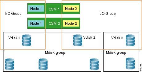
This section defines frequently-used SVC terms that are necessary to proceed with the configuration process (see Figure 2-1).
Figure 2-1 Graphical Representation of SVC Terms
Node
An instance of SVC that is running in the CSM. A CSM consists of two completely independent nodes. Each node is represented by an interface.
I/O group
SVC nodes are always used in pairs. A pair of SVC nodes is called an I/O group. The nodes in a given I/O group must reside in two separate CSMs. An I/O group acts as a storage controller in the fabric.
Cluster
A cluster can contain multiple I/O groups. All nodes in the cluster must run the same SVC image version. The IP address for a cluster must be assigned in the same subnet as the management interface.
MDisk
A representation of back end storage. Each cluster is configured so all the nodes in a cluster see the same set of MDisks.
VDisk
A virtual representation of a LUN that is exposed by the cluster to the hosts in a SAN. Each VDisk is independently associated with a single I/O group.
MDisk Group
A set of MDisks form a MDisk group. Storage for a VDisk originates from MDisks in a single MDisk group.
Host
One of more initiator Fibre Channel ports (pWWNs) form a host. A host is mapped to one or more VDisks. Hosts cannot directly access a MDisk.
Separating Hosts and Storage Devices
In order for SVC to virtualize the back-end storage to hosts, you must ensure that the hosts do not directly access the storage. You can separate hosts or disks using the concept of VSANs. The VSAN feature is specific to Cisco MDS 9000 Family switches. Alternatively, you can also use zones to separate hosts or disks.
Refer to the Cisco MDS 9000 Family Configuration Guide for further information on VSANs or zones.
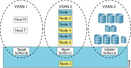
Each SVC interface is assigned a nWWN. A SVC interface consists of three N-ports:
•
•
•
Each N-port within an SVC interface is assigned a port World Wide Name (pWWN). The pWWNs and node World Wide Names (nWWNs) are preserved across switch reboots (see Figure 2-2).
Figure 2-2 Logical Representation of an SVC Interface
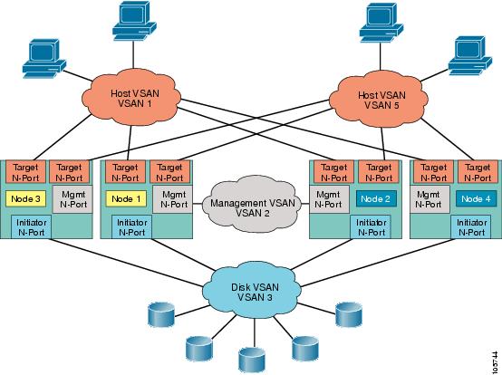
In Figure 2-3, provides a logical view of four SVC nodes in a SAN. These nodes are configured so the hosts do not have direct access to the disks.
By default, all N-ports reside in VSAN 1. You must explicitly remove them when necessary.
Figure 2-3 Logical Representation of a SAN
To configure a SVC interface and N-port VSANs in a Cisco MDS switch, follow these steps:
Verifying Interface Connectivity
This section lists the show commands that help verify the SVC interface state and the N-port association with the SVC interface.
Example 2-1 Displays Information for A Specified SVC Interface
switch# show interface svc 2/1svc2/1 is upNode WWN is 2e:ab:00:05:30:00:1a:e0Fabric WWN is 20:01:00:05:30:00:1a:deTarget N-port WWN is 2e:a5:00:05:30:00:1a:e0, vsan is 1, FCID is 0xe80003Initiator N-port WWN is 21:2e:00:05:30:00:00:21, vsan is 3, FCID is 0xea0004Mgmt N-port WWN is 2f:af:00:05:30:00:1a:e0, vsan is 2, FCID is 0xe800005 minutes input rate 2392 bits/sec, 299 bytes/sec, 0 frames/sec5 minutes output rate 2240 bits/sec, 280 bytes/sec, 0 frames/sec272 frames input, 89764 bytes0 discards, 0 errors232 frames output, 84176 bytes0 discards, 0 errorsExample 2-2 Displays N-port Connections for a Specified SVC Interface
switch# show svc session svc 2/1svc2/1:Target N-port WWN is 2e:a5:00:05:30:00:1a:e0, vsan is 1, FCID is 0xe80003pWWN 21:01:00:e0:8b:31:20:31, nWWN 20:01:00:e0:8b:31:20:31, FCID 0xe80200pWWN 21:00:00:e0:8b:11:29:31, nWWN 20:00:00:e0:8b:11:29:31, FCID 0xe80300Initiator N-port WWN is 21:2e:00:05:30:00:00:21, vsan is 3, FCID is 0xea0004pWWN 50:05:07:63:00:c8:9c:f9, nWWN 50:05:07:63:00:c0:9c:f9, FCID 0xea0000pWWN 50:05:07:63:00:c8:9c:fa, nWWN 50:05:07:63:00:c0:9c:fa, FCID 0xea0001Mgmt N-port WWN is 2f:af:00:05:30:00:1a:e0, vsan is 2, FCID is 0xe80000pWWN 2f:b9:00:05:30:00:1a:e0, nWWN 2f:b7:00:05:30:00:1a:e0, FCID 0xe80002pWWN 2f:ba:00:05:30:00:1a:e0, nWWN 2e:b3:00:05:30:00:1a:e0, FCID 0xe80003pWWN 2f:b8:00:05:30:00:1a:e0, nWWN 2e:ac:00:05:30:00:1a:e0, FCID 0xe80001Example 2-3 Displays the FCNS Database
switch# show fcns databaseVSAN 1:--------------------------------------------------------------------------FCID TYPE PWWN (VENDOR) FC4-TYPE:FEATURE--------------------------------------------------------------------------0xe80000 N 2e:a8:00:05:30:00:1a:e0 (Cisco) scsi-fcp:target svc0xe80003 N 2e:a5:00:05:30:00:1a:e0 (Cisco) scsi-fcp:target svc0xe80200 N 21:01:00:e0:8b:31:20:31 (QLogic) scsi-fcp:init0xe80300 N 21:00:00:e0:8b:11:29:31 (QLogic) scsi-fcp:initTotal number of entries = 4VSAN 2:--------------------------------------------------------------------------FCID TYPE PWWN (VENDOR) FC4-TYPE:FEATURE--------------------------------------------------------------------------0xe80000 N 2f:af:00:05:30:00:1a:e0 (Cisco) scsi-fcp:both svc0xe80001 N 2f:b8:00:05:30:00:1a:e0 (Cisco) scsi-fcp:both svcTotal number of entries = 2VSAN 3:--------------------------------------------------------------------------FCID TYPE PWWN (VENDOR) FC4-TYPE:FEATURE--------------------------------------------------------------------------0xea0000 N 50:05:07:63:00:c8:9c:f9 (IBM) scsi-fcp:target fc..0xea0001 N 50:05:07:63:00:c8:9c:fa (IBM) scsi-fcp:target fc..0xea0002 N 21:2e:00:05:30:00:00:23 (Cisco) scsi-fcp:init svcTotal number of entries = 3Assigning VSAN Numbers
When configuring SVC interfaces and N-port VSANs, the VSAN number can be any number from 1 to 4096. Only 64 VSANs for all initiator/mgmt/target (in total) are allowed—you can have initiator in VSANs 1-30, target in VSANs 31-60, and mgmt in VSANs 61-64). If the target, inititator, and mgmt overlap in any VSAN, each overlap is also included in the total VSAN count. A mgmt N-port can only exist in 4 of these 64 VSANs.
Multiple Initiators and Targets
You can create multiple N-ports for any SVC interface in different VSANs (see Figure 2-1).
Figure 2-4 Graphical Representation of SVC Terms