-
Cisco MDS 9000 Family SAN Volume Controller Configuration Guide
-
New and Changed Information
-
Full Book PDF
-
Preface
-
SVC Product Overview
-
Getting Started
-
Creating and Managing Clusters
-
Managing Back-end Storage
-
Managing Virtual Disks
-
Configuring Hosts
-
Configuring Copy Services
-
Upgrading CSM Software
-
Configuring SPAN on SVC Interfaces
-
Configuring a Dual Fabric SAN Environment
-
 Feedback
Table Of Contents
Creating and Managing Clusters
Deleting a node from a Cluster
Creating and Managing Clusters
This section explains the steps required to create clusters. To configure other SVC features or to access the switch after initial configuration you can use one of the following CLI or Graphical User Interface (GUI) options:
•
Cisco MDS 9000 Family CLI—to use the Cisco MDS CLI, follow the procedure specified in this guide.
Note
•
•
This chapter includes the following sections:
•
•
About CSM Nodes
A node provides virtualization, caching, migration and copy services to the SAN. Nodes are deployed in pairs with each pair of nodes forming an I/O group. The nodes belonging to the same I/O group MUST have different power domains. This entails that nodes of the same I/O group should come from two different CSMs. When a node fails within an I/O group then the other node in the I/O group will take over the responsibilities of the failed node. Data loss during a node failure is prevented by mirroring the IO read/write cache info across both the nodes in the I/O group.
About Clusters
Nodes are grouped into clusters of up to 2 pairs of nodes. These nodes are managed as a set (cluster), and present a single point of control for the user for configuration and service activity. For I/O purposes, so as to avoid a single point of loss of availability nodes will be grouped into pairs (I/O groups), with a single pair being responsible for serving I/O on a given VDisk. I/O traffic for a particular VDisk is, at any one time, handled exclusively by the nodes in a single I/O group. Thus, although a cluster may have many nodes within it, the nodes handle i/o in independent pairs. This means that the i/o capability of a cluster scales well, since additional throughput can simply be obtained by adding additional I/O Groups.
There are some circumstances when all the nodes in the cluster do act together rather than in pairs. At any one time, a single node in the cluster is used to manage configuration activity. The node at which the cluster got created will start off as the configuration node. This configuration node manages a cache of the configuration information that describes the cluster configuration and provides a focal point for configuration commands. Similarly, at any one time, a single node acts as the managing node for overall management of the cluster. If the configuration node or managing node fails, another node in the cluster will take over their responsibilities. The nodes also act together to implement the data migration function described in "Configuring Copy Services."
There are several advantages to managing a set of nodes as a cluster.
•
•
•
Physical Topology
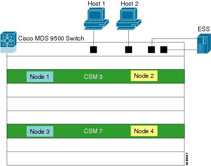
In Figure 3-1, CSMs reside in slots 3 and 7 in a Cisco MDS 9500 Series switch. CSM 3 has two nodes identified as interface svc 3/1 and interface svc 3/2. CSM 7 has two nodes identified as interface svc 7/1 and interface svc 7/2. These four interfaces are configured to form a 4-node cluster.
•
•
These two I/O groups form a SVC cluster. So SVC interfaces 3/1, 3/2, 7/1, and 7/2 belong to one cluster
Figure 3-1 also shows two hosts and a back-end storage device. This physical topology serves as an example in the following sections to understand SVC configurations.
Figure 3-1 Sample SVC Configuration Using Cisco MDS Switches
Selecting Nodes for a Cluster
To configure a 4-node sample configuration, follow these steps.
Step 1
switch1# svc-configStep 2
switch1(svc)# show nodes local-------------------------------------------------------------------------------Node cluster config cluster node swnode status status version-------------------------------------------------------------------------------svc3/1 No unconfigured free 1.3(1)svc3/2 No unconfigured free 1.3(1)svc7/1 No unconfigured free 1.3(1)svc7/2 No unconfigured free 1.3(1)
Isolating Management Traffic
Management traffic is isolated for CSM nodes that are part of the same cluster using a traffic domain separator (for example VSANs or zones).
To create a separate traffic domain using VSANs, follow these steps.
Step 1
switch1(svc)# exitswitch1# config tswitch1(config)#Step 2
switch1(config)# vsan databaseswitch1(config-vsan-db)# vsan 2switch1(config-vsan-db)# exitswitch1(config)#Step 3
switch1(config)# interface svc3/1switch1(config-if)# mgmt vsan 2switch1(config-if)# no mgmt vsan 1 <--- You have to explicitly remove from vsan 1switch1(config-if)# no shutswitch1(config-if)# exitswitch1(config)# interface svc3/2switch1(config-if)# mgmt vsan 2switch1(config-if)# no mgmt vsan 1 <--- You have to explicitly remove from vsan 1switch1(config-if)# no shutswitch1(config-if)# exitswitch1(config)# interface svc7/1switch1(config-if)# mgmt vsan 2switch1(config-if)# no mgmt vsan 1 <--- You have to explicitly remove from vsan 1switch1(config-if)# no shutswitch1(config-if)# exitswitch1(config)# interface svc7/2switch1(config-if)# mgmt vsan 2switch1(config-if)# no mgmt vsan 1 <--- You have to explicitly remove from vsan 1switch1(config-if)# no shutswitch1(config-if)# exitswitch1(config)#Step 4
switch1# show fcns database vsan 2VSAN 2:--------------------------------------------------------------------------FCID TYPE PWWN (VENDOR) FC4-TYPE:FEATURE--------------------------------------------------------------------------0x770000 N 22:32:00:05:30:00:11:69 (Cisco) scsi-fcp:both svc0x770001 N 22:33:00:05:30:00:11:69 (Cisco) scsi-fcp:both svc0x770002 N 22:34:00:05:30:00:11:69 (Cisco) scsi-fcp:both svc0x770003 N 22:35:00:05:30:00:11:69 (Cisco) scsi-fcp:both svcTotal number of entries = 4Step 5
switch1(config)# zone default-zone permit vsan 2switch1(config)#
Creating a Cluster
Create a cluster called SampleCluster using one node for the cluster creating This example uses interface svc3/1 to begin the cluster creation process. It also uses the 10.1.1.100 IP address that is in the same subnet as switch 1's management's IP network.
Note
To create a cluster, follow these steps.
Step 1
switch1# svc-configswitch1(svc)# cluster add SampleCluster ip 10.1.1.100 node svc3/1Cluster creation going on. Please wait....---> This process takes a few seconds.Step 2
switch1(svc)# show nodes local-------------------------------------------------------------------------------Node cluster config cluster node swnode status status version-------------------------------------------------------------------------------svc3/1 SampleCluster Yes active active 1.3(1)svc3/2 No unconfigured free 1.3(1)svc7/1 No unconfigured free 1.3(1)svc7/2 No unconfigured free 1.3(1)Step 3
switch1(svc)# show cluster SampleCluster nodesNode node1 is online(3)Node WWN is 22:26:00:05:30:00:11:69Serial number is JAB072006AQUnique id is 01:00:07:20:30:36:41:51Node is in config modeNode is part of iogroup id 1 name io_grp0The configured node is the only node in this cluster.
Adding Nodes to Clusters
Once the initial node is used to create a cluster, you can add other required nodes to the same cluster. You can determine which nodes are available by issuing the show cluster cluster-name nodes candidate command.
To add other nodes to a cluster, follow these steps.
Step 1
a.
switch1(svc)# show cluster SampleCluster nodes candidate-----------------------------------------------------------------------------NODE NWWN-----------------------------------------------------------------------------switch1.7.2 21:28:00:05:30:00:11:69switch1.7.1 21:26:00:05:30:00:11:69switch1.3.2 21:2a:00:05:30:00:11:69This example has 3 other SVC nodes in the SAN that are candidate nodes for this cluster. The node name is an encoding of the <switch-name>.<slot-number>.<node-ID>. For example: switch1.7.2 is in the switch named switch1 at slot 7 node 2.
Caution
b.
switch1(svc)# cluster config SampleClusterswitch1(svc-cluster)# node nwwn 21:28:00:05:30:00:11:69 iogroup 1switch1(svc-cluster)# node nwwn 21:26:00:05:30:00:11:69 iogroup 2switch1(svc-cluster)# node nwwn 21:2a:00:05:30:00:11:69 iogroup 2switch(svc-cluster)# exit
Verifying Nodes in a Cluster
After the cluster is created with the required nodes, you can verify the status of each node in the cluster, status of each node, and the associated I/O group to ensure the configuration is functioning as desired.
The node state transitions from adding to pending to online during the cluster creation process.
To verify the nodes in a cluster, follow these steps.
Step 1
switch1(svc)# show cluster SampleCluster nodesNode node1 is online(3)Node WWN is 22:26:00:05:30:00:11:69Serial number is JAB072006AQUnique id is 01:00:07:20:30:36:41:51Node is in config modeNode is part of iogroup id 1 name io_grp0Node node2 is online(3)Node WWN is 21:28:00:05:30:00:11:69Serial number is JAB076607H8Unique id is 01:00:07:66:30:37:48:38Node is in non config modeNode is part of iogroup id 1 name io_grp0Node node3 is pending(2)Node WWN is 21:26:00:05:30:00:11:69Serial number is JAB071007H8Unique id is 01:00:07:10:30:37:48:38Node is in non config modeNode is part of iogroup id 2 name io_grp1Node node4 is adding(6)Node WWN is 00:00:00:00:00:00:00:00Serial number is JAB076606AQUnique id is 01:00:07:66:30:36:41:51Node is in non config modeNode is part of iogroup id 2 name io_grp1Step 2
switch1(svc)# show cluster SampleCluster iogroupID Name Node count VLUN count--- --------------- ---------- ---------1 io_grp0 2 02 io_grp1 2 03 io_grp2 0 04 io_grp3 0 05 recovery_io_grp 0 0
Note
Step 3
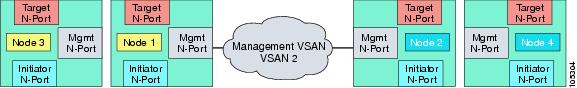
switch(svc)# show nodes localConfig Cluster Node SwNode Cluster node status status version-------- ---------------- ------ ------- ------ -----------svc3/1 SampleCluster Yes Active Active 1.3(1)svc3/2 SampleCluster No Active Active 1.3(1)svc7/1 SampleCluster No Active Active 1.3(1)svc7/2 SampleCluster No active Active 1.3(1)The 4-node cluster is now created with the nodes communicating with each other in VSAN 2. All nodes in the switch are active and are part of cluster named SampleCluster. The SVC config node is svc3/1 (see Figure 3-2).
Figure 3-2 Creating a 4-Node Cluster
Deleting a node from a Cluster
A node has to be removed from a cluster using the no node command in the cluster config mode.
To delete a node that is online, follow these steps.
Step 1
switch1# svc-configswitch1(svc)# cluster config SampleClusterStep 2
switch1(svc-cluster)# no node nwwn 21:28:00:05:30:00:11:69 iogroup 1To delete a node that is in an offline state, follow these steps.
Step 1
switch1# svc-configswitch1(svc)# cluster config SampleClusterStep 2
switch1(svc-cluster)# no node name node3When you delete a node in a cluster, the node is removed from the cluster state. In addition, the local state of the deleted node is also updated to indicate that it is no longer a part of any cluster.
If the node is offline, the local state of the deleted node should be explicitly updated using the node svc x/y delete command.
Deleting a Cluster
The MDS CLI does not use an explicit command to delete a cluster. The cluster is automatically deleted when the last node in the cluster is deleted.