-
Cisco MDS 9000 Family SAN Volume Controller Configuration Guide
-
New and Changed Information
-
Full Book PDF
-
Preface
-
SVC Product Overview
-
Getting Started
-
Creating and Managing Clusters
-
Managing Back-end Storage
-
Managing Virtual Disks
-
Configuring Hosts
-
Configuring Copy Services
-
Upgrading CSM Software
-
Configuring SPAN on SVC Interfaces
-
Configuring a Dual Fabric SAN Environment
-
 Feedback
Table Of Contents
Configuring a Dual Fabric SAN Environment
Configuring a Dual Fabric SAN Environment
Dual fabric SAN environments are an important configuration requirement. You can use CSM modules in combination with the Inter-VSAN Routing (IVR) feature to operate across two isolated fabrics.
This chapter includes the following sections:
Overview
Redundant isolated fabrics (fabrics without an ISL connecting them) are used to ensure that disruptions in one fabric do not affect the other. Hosts and disk subsystems in such an environment can be configured to ensure that at least one port remains attached to each fabric.
Basic SVC Requirements
SVC has the following requirements:
•
All SVC nodes must be able to communicate with each other in the management VSAN.
•
In a redundant, dual fabric configuration, the Cisco MDS Inter-VSAN Routing (IVR) feature must be used in order to satisfy these basic SVC requirements. IVR provides the same benefit of keeping the two fabrics separate while providing the connectivity required to implement SVC. Refer to Cisco MDS 9000 Family Configuration Guide for more information on IVR.
Dual Fabric Prerequisites
To configure a dual fabric SAN environment using IVR and SVC, verify the following requirements:
•
•
•
•
•
•
•
•
•
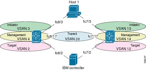
Sample Configuration
Figure 10-1 displays a dual fabric SAN environment example used in this configuration. The procedure to configure this sample scenario is provided after the illustration.
Figure 10-1 Traffic Isolation and Connectivity Using SVC and IVR
To configure a dual fabric SAN environment in the first fabric, follow these steps:
Step 1
switch1# show wwn switchSwitch WWN is 20:00:00:05:30:00:41:deswitch2# show wwn switchSwitch WWN is 20:00:00:05:30:00:07:1eStep 2
switch1# configure terminalswitch1(config)# vsan databaseswitch1(config-vsan-db)# vsan 2switch1(config-vsan-db)# vsan 2 interface fc8/2 <-- target portswitch1(config-vsan-db)# vsan 3switch1(config-vsan-db)# vsan 3 interface fc8/3 <-- initiator portswitch1(config-vsan-db)# vsan 4switch1(config-vsan-db)# vsan 20switch1(config-vsan-db)# exitswitch1(config)#Step 3
Sw1(config)# fcdomain domain 2 static vsan 2Sw1(config)# fcdomain domain 3 static vsan 3Sw1(config)# fcdomain domain 4 static vsan 4Sw1(config)# fcdomain domain 20 static vsan 20Step 4
switch1(config)# int svc 1/1 - 2switch1(config-if)# no initiator vsan 1switch1(config-if)# initiator vsan 2switch1(config-if)# no target vsan 1switch1(config-if)# target vsan 3switch1(config-if)# no mgmt vsan 1switch1(config-if)# mgmt vsan 4switch1(config-if)# exitStep 5
switch1(config)# no zone default-zone permit vsan 20Step 6
switch1(config)# zone name z_2 vsan 2switch1(config-zone)# member pwwn 20:06:00:a0:b8:0f:6c:34 <-- targetswitch1(config-zone)# member pwwn 27:8d:00:05:30:00:33:2a <-- svc initiatorswitch1(config-zone)# member pwwn 27:89:00:05:30:00:33:2a <-- svc initiatorswitch1(config-zone)# exitswitch1(config)# zoneset name zs_2 vsan 2switch1(config-zoneset)# member z_2switch1(config-zoneset)# exitswitch1(config)# zoneset activate name zs_2 vsan 2Zone set activation is now initiated. Check zone status.Step 7
switch1(config)# zone name z_3 vsan 3switch1(config-zone)# member pwwn 21:01:00:e0:8b:29:f0:04 <-- initiatorswitch1(config-zone)# member pwwn 27:8e:00:05:30:00:33:2a <-- svc targetswitch1(config-zone)# member pwwn 27:8a:00:05:30:00:33:2a <-- svc targetswitch1(config-zone)# exitswitch1(config)# zoneset name zs_3 vsan 3switch1(config-zoneset)# member z_3switch1(config-zoneset)# exitswitch1(config)# zoneset activate name zs_3 vsan 3Zone set activation is now initiated. Check zone status.Step 8
switch1(config)# zone name z_4 vsan 4switch1(config-zone)# member pwwn 27:90:00:05:30:00:33:2a <-- svc mgmtswitch1(config-zone)# member pwwn 27:8f:00:05:30:00:33:2a <-- svc mgmtswitch1(config-zone)# exitswitch1(config)# zoneset name zs_4 vsan 4switch1(config-zoneset)# member z_4switch1(config-zoneset)# exitswitch1(config)# zoneset activate name zs_4 vsan 4Zone set activation is now initiated. Check zone status.Step 9
switch1(config)# ivr enableswitch1(config)# ivr vsan-topology databaseswitch1(config-ivr-topology-db)# autonomous-fabric-id 1 switch-wwn 20:00:00:05:30:00:41:de vsan-ranges 2,4,20switch1(config-ivr-topology-db)# autonomous-fabric-id 1 switch-wwn 20:00:00:05:30:00:07:1e vsan-ranges 12,14,20switch1(config-ivr-topology-db)# exitswitch1(config)# ivr vsan-topology activateStep 10
switch1(config)# ivr zone name ivr_2_12switch1(config-ivr-zone)# member pwwn 27:8d:00:05:30:00:33:2a vsan 2switch1(config-ivr-zone)# member pwwn 27:89:00:05:30:00:33:2a vsan 2switch1(config-ivr-zone)# member pwwn 20:07:00:a0:b8:0f:6c:34 vsan 12switch1(config-ivr-zone)# exitStep 11
switch1(config)# ivr zone name ivr_12_2switch1(config-ivr-zone)# member pwwn 23:30:00:05:30:00:8d:e2 vsan 12switch1(config-ivr-zone)# member pwwn 23:31:00:05:30:00:8d:e2 vsan 12switch1(config-ivr-zone)# member pwwn 20:06:00:a0:b8:0f:6c:34 vsan 2switch1(config-ivr-zone)# exitStep 12
switch1(config)# ivr zone name ivr_4_14switch1(config-ivr-zone)# member pwwn 27:90:00:05:30:00:33:2a vsan 4switch1(config-ivr-zone)# member pwwn 27:8f:00:05:30:00:33:2a vsan 4switch1(config-ivr-zone)# member pwwn 23:34:00:05:30:00:8d:e2 vsan 14switch1(config-ivr-zone)# member pwwn 23:35:00:05:30:00:8d:e2 vsan 14switch1(config-ivr-zone)# exitStep 13
switch1(config)# ivr zoneset name ivr_zsswitch1(config-ivr-zoneset)# member ivr_2_12switch1(config-ivr-zoneset)# member ivr_12_2switch1(config-ivr-zoneset)# member ivr_4_14switch1(config-ivr-zoneset)# exitswitch1(config)# ivr zoneset activate name ivr_zsZone set activation is now initiated. Check inter-VSAN zoneset status.If any VSANs are configured to permit the default-zone, then you must use the force option to activate the IVR zone set
switch1(config)# ivr zoneset activate name ivr_zs forceZone set activation is now initiated. Check inter-VSAM zoneset status.Step 14
switch1(config)# interface fc8/2, fc8/3switch1(config-if)# no shutdownswitch1(config-if)# exitswitch1(config)# interface fc8/17switch1(config-if)# switchport trunk mode onswitch1(config-if)# switchport mode Eswitch1(config-if)# no shutdownswitch1(config-if)# switchport trunk allowed vsan 20switch1(config-if)# exitYou have now configured the first fabric for the dual fabric SAN environment displayed in Figure 10-1.
To configure a dual fabric SAN environments in the second fabric, follow these steps:
Step 1
Step 2
switch2# configure terminalswitch2(config)# vsan databaseswitch2(config-vsan-db)# vsan 12switch2(config-vsan-db)# vsan 12 interface fc7/2 <-- target portswitch2(config-vsan-db)# vsan 13switch2(config-vsan-db)# vsan 13 interface fc7/3 <-- initiator portswitch2(config-vsan-db)# vsan 14switch2(config-vsan-db)# vsan 20switch2(config-vsan-db)# exitStep 3
switch2(config)# fcdomain domain 12 static vsan 12switch2(config)# fcdomain domain 13 static vsan 13switch2(config)# fcdomain domain 14 static vsan 14switch2(config)# fcdomain domain 40 static vsan 20Step 4
switch2(config)# int svc 2/1 - 2switch2(config-if)# no initiator vsan 1switch2(config-if)# initiator vsan 12switch2(config-if)# no target vsan 1switch2(config-if)# target vsan 13switch2(config-if)# no mgmt vsan 1switch2(config-if)# mgmt vsan 14switch2(config-if)# exitStep 5
switch1(config)# no zone default-zone permit vsan 20Step 6
switch2(config)# zone name z_12 vsan 12switch2(config-zone)# member pwwn 20:07:00:a0:b8:0f:6c:34 <-- targetswitch2(config-zone)# member pwwn 23:30:00:05:30:00:8d:e2 <-- svc initiatorswitch2(config-zone)# member pwwn 23:31:00:05:30:00:8d:e2 <-- svc initiatorswitch2(config-zone)# exitswitch2(config)# zoneset name zs_12 vsan 12switch2(config-zoneset)# member z_12switch2(config-zoneset)# exitswitch2(config)# zoneset activate name zs_12 vsan 12Zone set activation is now initiated. Check zone status.Step 7
switch2(config)# zone name z_13 vsan 13switch2(config-zone)# member pwwn 21:00:00:e0:8b:09:f0:04 <-- initiatorswitch2(config-zone)# member pwwn 23:32:00:05:30:00:8d:e2 <-- svc targetswitch2(config-zone)# member pwwn 23:33:00:05:30:00:8d:e2 <-- svc targetswitch2(config-zone)# zoneset name zs_13 vsan 13switch2(config-zoneset)# member z_13switch2(config-zoneset)# zoneset activate name zs_13 vsan 13Zone set activation is now initiated. Check zone status.Step 8
switch2(config)# zone name z_14 vsan 14switch2(config-zone)# member pwwn 23:34:00:05:30:00:8d:e2 <-- svc mgmtswitch2(config-zone)# member pwwn 23:35:00:05:30:00:8d:e2 <-- svc mgmtswitch2(config-zone)# zoneset name zs_14 vsan 14switch2(config-zoneset)# member z_14switch2(config-zoneset)# zoneset activate name zs_14 vsan 14Zone set activation is now initiated. Check zone status.Step 9
switch2(config)# ivr vsan-topology databaseswitch2(config-ivr-topology-db)# autonomous-fabric-id 1 switch-wwn 20:00:00:05:30:00:41:de vsan-ranges 2,4,20switch2(config-ivr-topology-db)# autonomous-fabric-id 1 switch-wwn 20:00:00:05:30:00:07:1e vsan-ranges 12,14,20switch2(config-ivr-topology-db)# exitswitch2(config)# ivr vsan-topology activateStep 10
switch2(config)# ivr zone name ivr_2_12switch2(config-ivr-zone)# member pwwn 27:8d:00:05:30:00:33:2a vsan 2switch2(config-ivr-zone)# member pwwn 27:89:00:05:30:00:33:2a vsan 2switch2(config-ivr-zone)# member pwwn 20:07:00:a0:b8:0f:6c:34 vsan 12switch2(config-ivr-zone)# exitStep 11
switch2(config)# ivr zone name ivr_12_2switch2(config-ivr-zone)# member pwwn 23:30:00:05:30:00:8d:e2 vsan 12switch2(config-ivr-zone)# member pwwn 23:31:00:05:30:00:8d:e2 vsan 12switch2(config-ivr-zone)# member pwwn 20:06:00:a0:b8:0f:6c:34 vsan 2switch2(config-ivr-zone)# exitStep 12
switch2(config)# ivr zone name ivr_4_14switch2(config-ivr-zone)# member pwwn 27:90:00:05:30:00:33:2a vsan 4switch2(config-ivr-zone)# member pwwn 27:8f:00:05:30:00:33:2a vsan 4switch2(config-ivr-zone)# member pwwn 23:34:00:05:30:00:8d:e2 vsan 14switch2(config-ivr-zone)# member pwwn 23:35:00:05:30:00:8d:e2 vsan 14switch2(config-ivr-zone)# exitStep 13
switch2(config)# ivr zoneset name ivr_zsswitch2(config-ivr-zoneset)# member ivr_2_12switch2(config-ivr-zoneset)# member ivr_12_2switch2(config-ivr-zoneset)# member ivr_4_14switch2(config-ivr-zoneset)# exitswitch2(config)# ivr zoneset activate name ivr_zsZone set activation is now initiated. Check inter-VSAN zoneset status.If any VSANs are configured to permit the default-zone, then you must use the force option to activate the IVR zone set
switch1(config)# ivr zoneset activate name ivr_zs forceZone set activation is now initiated. Check inter-VSAN zoneset status.Step 14
switch2(config)# interface fc7/2, fc7/3switch2(config-if)# no shutdownswitch2(config-if)# exitswitch2(config)# interface fc7/17switch1(config-if)# switchport trunk mode onswitch1(config-if)# switchport mode Eswitch2(config-if)# no shutdownswitch2(config-if)# switchport trunk allowed vsan 20switch2(config-if)# exitYou have now configured the second fabric for the dual fabric SAN environment displayed in Figure 10-1.