Cisco MDS 9216 Switch Hardware Installation Guide
Technical Specifications

Table Of Contents

Technical Specifications

Switch Specifications

Module Specifications

Weight of Modules

Power Specifications

Specifications for the Cisco MDS 9216 Switch Power Supplies

Component Power Requirements and Heat Dissipation Specifications

CCisco MDS 9216 Sample Power and Heat Dissipation Calculation

Supported Power Cords and Plugs

Power Cords

Jumper Power Cord


Technical Specifications


This appendix includes the following information for the Cisco MDS 9216 Switch:

Switch Specifications

Module Specifications

Weight of Modules

Supported Power Cords and Plugs


Note Specifications for cables and connectors are provided in "Cable and Port Specifications."


Switch Specifications

Table C-1 lists the environmental specifications for the Cisco MDS 9216 Switch.

Table C-1 Environmental Specifications for the Cisco MDS 9216 Switch  

Description
Specification

Temperature, ambient operating

32 to 104°F (0 to 40°C)

Temperature, ambient nonoperating and storage

-40 to 158°F (-40 to 70°C)

Humidity (RH), ambient (noncondensing) operating

10 to 90%

Humidity (RH), ambient (noncondensing) nonoperating and storage

5 to 95%

Altitude, operating

-197 to 6500 ft (-60 to 2000 m)

Noise levels

70 dB


Table C-2 lists the physical specifications for the Cisco MDS 9216 Switch.

Table C-2 Physical Specifications for the Cisco MDS 9216 Switch 

Description
Specification

Dimensions (HxWxD)

5.25 x 17.5 x 22.75 in. (13.3 x 44.5 x 57.8 cm)
Chassis requires 3 RU1 .
Chassis depth including cable guide is 27.75 in. (70.3 cm).

Weight

Chassis only: 31 lb (14.1 kg).
Chassis configured with one supervisor module, fan module, and two power supplies: 45 lb (20.4 kg)

Power supply

845-W AC input for each power supply

Airflow

300 lfm2 through system fan module, or 80 cfm3 per supervisor, switching, or services module. Total of 160 cfm if slot 2 is filled.
Spacing requirements:

If installed in a cabinet, a minimum of 2.5 in. (6.4 cm) is required between the chassis air vents and the cabinet walls.

If installed in an open rack (no side panels), the horizontal distance required between the chassis and any devices that exhaust air towards the chassis is a minimum of 6 in. (15.2 cm), and the distance required between the chassis air vents and any walls is a minimum of 2.5 in. (6.4 cm).

1 RU = rack unit; 1 RU = 1.75 inches (4.45 cm)

1 2. lfm = linear feet per minute

1 3. cfm = cubic feet per minute


Module Specifications

Table C-3 lists the specifications for the Cisco MDS 9216 Switch supervisor module (which is fixed in the chassis) and the switching and services modules.

Table C-3 Cisco MDS 9216 Switch Module Specifications 

Description
Specification
Environmental Requirements

Temperature, ambient operating

32 to 104°F (0 to 40°C)

Temperature, ambient nonoperating and storage

-40 to 167°F (-40 to 75°C)

Humidity (RH), ambient (noncondensing) operating

10 to 90%

Altitude operating

-197 to 6500 ft (-60 to 2000 m)

Physical Characteristics

Dimensions

1.75 x15.5 x16.5 in. (4.4 x 39.4 x 41.9 cm)

Note These are the maximum dimensions of faceplate and board, and include connectors on board.

Weight

8 to 11.5 lb (1.4 to 5.2 kg)


Table C-4 lists the specifications for the batteries on the Cisco MDS 9000 Family Caching Services Module.

Table C-4 Caching Services Module Battery Specifications 

Attribute
Value

Nominal voltage

9.6 V

Rated capacity

Typical discharge capacity at 0.2C rate: 2100 mAh

Minimum discharge capacity at 0.2C rate: 2000 mAh

Minimum discharge capacity at 5C rate: 1800 mAh
(1V/cell discharge cut-off)

Discharge

The battery is capable of continuous discharge from +5 to +60°C at 5C-rate

Charge

From 0 to 15°C at C/10 rate and from +15 to +40°C at C/2-rate

Storage temperature

0 to +35°C

Relative humidity range

From 5 to 90%


Weight of Modules

Table C-5 lists the weight for each module in the Cisco MDS 9000 Family.

Table C-5 Weight of Modules in the Cisco MDS 9000 Family

Module
Weight

16-port FC switching module

9 lb (4.1 kg)

32-port FC switching module

9 lb (4.1 kg)

ASM

11 lb (5 kg)

SSM

11 lb (5 kg)

CSM

11.5 lb (5.2 kg)

IPS-4

9 lb (4.1 kg)

IPS-8

10 lb (4.5 kg)

MPS-14/2

10 lb (4.5 kg)

Supervisor for MDS 9500 Series

9 lb (4.1 kg)

Supervisor for MDS 9200 Series

9 lb (4.1 kg)


Power Specifications

This section includes the following information:

Specifications for the Cisco MDS 9216 Switch Power Supplies

Component Power Requirements and Heat Dissipation Specifications

Specifications for the Cisco MDS 9216 Switch Power Supplies

Table C-6 lists the specifications for the Cisco MDS 9216 Switch power supply, which is 845 W and accepts AC input.

Table C-6 Specifications for the Cisco MDS 9216 Switch Power Supply 

Type

Autoranging input with power factor corrector

Voltage

100 to 240 VAC (±10%)

Current rating

12 A at 100 to 120 VAC
5 A at 200 to 240 VAC

Frequency

50/60 Hz (nominal) (±3 Hz for full range)

Output capacity

845 W

Output voltage

+3.3 V at 10 A
+50 V at 16.2 A


Note For plug current ratings, see Figure C-1.


Component Power Requirements and Heat Dissipation Specifications

Consider heat dissipation when sizing the air-conditioning requirements for an installation. The power and heat associated with a Cisco MDS 9216 Switch varies based upon the following considerations:

Switching module type and number of switching modules installed

Average switching traffic levels

Table C-7 lists the power requirements and heat dissipation for the components of the Cisco MDS 9216 Switch.


Note Unless noted otherwise, the data in Table C-7 is based on worst-case conditions. Typical numbers are approximately 30 percent below the numbers listed here.


Table C-7 Power Requirements and Heat Dissipation for the 845-W Power Supply      

Module Type /
Product Number
Power Required (watts)
Heat Dissipation (BTU/hr)
Input Current
90 VAC (amps)
120 VAC (amps)
180 VAC (amps)
240 VAC (amps)

Cisco MDS 9216 chassis with fan module DS-C9216-K9

38

164

0.53

0.40

0.27

0.20

Fixed Cisco MDS 9216 supervisor module (16-port FC module, 1Gbps/2Gbps)

220

940

3.05

2.29

1.53

1.15

16-port FC module,
1Gbps/2Gbps
DS-X9016

220

940

3.05

2.29

1.53

1.15

32-port FC module, 1Gbps/2Gbps
DS-X9032

200

855

2.78

2.08

1.39

1.04

MPS-14/2 DS-X9302-14K9

227

970

3.15

2.37

1.57

1.19

4-port IPS module
DS-X9304- SMIP

185

789

2.57

1.93

1.28

0.96

8-port IPS module
DS-X9308- SMIP

220

940

3.05

2.29

1.53

1.15

32-port ASM,
DS-X9032-SMV

295

1260

4.10

3.07

2.05

1.54

32-port SSM,
DS-X9032-SSM

295

1260

4.10

3.07

2.05

1.54

CSM
DS-X9560-SMC

210

907

2.95

2.22

1.48

1.11


CCisco MDS 9216 Sample Power and Heat Dissipation Calculation

Table C-8 provides a sample calculation of power and heat dissipation for the following hardware configuration at maximum wattage:

Cisco MDS 9216 chassis, including two 845-W AC power supplies

Fixed supervisor module, with 16 Fibre Channel ports

One 32-port Fibre Channel switching module

Table C-8 Sample Calculation for Power and Heat Dissipation for Cisco MDS 9216 Switch

Module Type /
Product Number
Qty
Power Required (watts)
Heat Dissipation (BTU/hr)
Input Current
90 VAC (amps)
120 VAC (amps)
180 VAC (amps)
240 VAC (amps)

Cisco MDS 9216 chassis with fan module
DS-C9216-K9

1

38

164

0.53

0.40

0.27

0.20

Fixed supervisor module (16-port FC module, 1Gbps/2Gbps)

1

220

940

3.05

2.29

1.53

1.15

32-port FC module,
1Gbps/2Gbps
DS-X9032

1

200

855

2.78

2.08

1.39

1.04

Total


458

1959

6.36

4.77

3.19

2.39


Supported Power Cords and Plugs

A separate power cord is provided for each power supply. Standard power cords or jumper power cords are available for connection to a power distribution unit having IEC 60320 C13 outlet receptacles. The jumper power cords, for use in cabinets, are available as an option instead of the standard power cords.

Power Cords

The standard power cords have an IEC C15 connector on the end that plugs into the switch. The optional jumper power cords have an IEC C15 connector on the end that plugs into the switch, and an IEC C14 connector on the end that plugs into an IEC C13 outlet receptacle. Only the standard power cords or jumper power cords provided with the switch are supported.

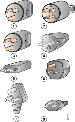
Figure C-1 shows the supported power supply plugs for the Cisco MDS 9216 Switch.

Figure C-1 845-W Power Supply Plugs

1

Argentina,
IRAM 2073 plug (10 A)

5

Italy
1/3G plug, CEI 23-16 (10 A)

2

North America
NEMA 5-15P plug (15 A)

6

United Kingdom
BS89/13, BS 1363/A
(13A; replaceable fuse)

3

Australia, New Zealand
SAA/3 plug, AS/NZS 3112-1993 (10 A)

7

South Africa
EL 208, SABS 164-1 (10 A)

4

Europe
VIIG Plug, CEE (7) VII (16 A)

8

Switzerland
12G SEV 1011 (10 A)


Jumper Power Cord

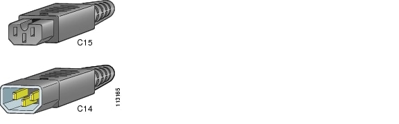
Figure C-2 shows the 250 VAC 13 A C14 and C15 connectors on the optional jumper power cord for the Cisco MDS 9216 Switch. The C15 connector connects into the C16 inlet on the Cisco MDS 9216 Switch power supply, while the C14 connector connects into the C13 receptacle of a power distribution unit for a cabinet. The power cord product ID is CAB-C15-CBN.

Figure C-2 End of C14 and C15 Connectors on Jumper Power Cord for Cisco MDS 9216 Switch