Feedback
Table Of Contents
Connecting the Console Port to a Computer Using the DB-25 Adapter
Connecting the Console Port to a Computer Using the DB-9 Adapter
Connecting the COM1 Port to a Modem
SFP Transceiver Specifications
Cisco Fibre Channel SFP Transceivers
General Specifications for Cisco Fibre Channel SFP Transceivers
Environmental and Electrical Specifications for Cisco Fibre Channel SFP Transceivers
Cisco Gigabit Ethernet/Fibre Channel Transceivers
General Specifications for Cisco Gigabit Ethernet/Fibre Channel SFP Transceivers
General Specifications for Cisco CWDM SFP Transceivers
Environmental and Electrical Specifications for Cisco CWDM SFP Transceivers
Optical Specifications for Cisco CWDM SFP Transceivers
Cisco Gigabit Ethernet Transceivers
General Specifications for Cisco Gigabit Ethernet SFP Transceiver
Environmental and Electrical Specifications for Cisco Gigabit Ethernet SFP Transceiver
Cable and Port Specifications
This appendix includes the following information:
•
SFP Transceiver Specifications
Cables and Adapters Provided
The Cisco MDS 9216 Switch accessory kit includes the following items:
•
•
•
•
•
•
Note
Note
Console Port
The console port is an asynchronous RS-232 serial port with an RJ-45 connector. You can use the RJ-45 to RJ-45 rollover cable and the RJ-45 to DB-25 female DTE adapter or the RJ-45 to DB-9 female DTE adapter to connect the console port to a computer running terminal emulation software.
Console Port Pinouts
Table D-1 lists the pinouts for the console port on the Cisco MDS 9216 Switch.
Table D-1 Console Port Pinouts
11
RTS
2
DTR
3
TxD
4
GND
5
GND
6
RxD
7
DSR
8
CTS
1 Pin 1 is connected internally to pin 8.
Connecting the Console Port to a Computer Using the DB-25 Adapter
You can use the RJ-45 to RJ-45 rollover cable and RJ-45 to DB-25 female DTE adapter (labeled "Terminal") to connect the console port to a computer running terminal emulation software. Table D-2 lists the pinouts for the console port, the RJ-45 to RJ-45 rollover cable, and the RJ-45 to DB-25 female DTE adapter.
Connecting the Console Port to a Computer Using the DB-9 Adapter
You can use the RJ-45 to RJ-45 rollover cable and RJ-45 to DB-9 female DTE adapter (labeled "Terminal") to connect the console port to a computer running terminal emulation software. Table D-3 lists the pinouts for the console port, the RJ-45 to RJ-45 rollover cable, and the RJ-45 to DB-9 female DTE adapter.
COM1 Port
The COM1 port is a serial port with a DB-9 connector, and can be connected to a modem using the adapters provided in the accessory kit.
Note
COM1 Port Pinouts
Table D-4 lists the pinouts for the COM1 port on the Cisco MDS 9216 Switch.
Connecting the COM1 Port to a Modem
You can use the green RJ-45 to DB-9 female DTE adapter (labeled "FOR DS-C9216-K9 ONLY") to connect to the COM1 port, and the RJ-45 to DB-25 male DCE adapter (labeled "Modem") to connect to the modem, then connect the adapters with the RJ-45 to RJ-45 rollover cable.
Note
Table D-5 lists the pinouts for the COM1 port, the RJ-45 to DB-9 adapter, RJ-45 to RJ-45 rollover cable, and the RJ-45 to DB-25 male DCE adapter.
MGMT 10/100 Ethernet Port
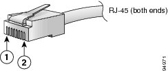
The MGMT 10/100 Ethernet port is an Ethernet port with an RJ-45 connector. You can use a modular, RJ-45, straight-through UTP cable to connect the management port to an external hub, switch, or router (see Figure D-1).
Figure D-1 RJ-45 Interface Cable Connector
Table D-6 lists the connector pinouts and signal names for a 10/100BASE-T management port (MDI) cable.
Note
Table D-6 10/100BASE-T Management Port Cable Pinouts (MDI)
1
TD+
2
TD-
3
RD+
6
RD-
4
Not used
5
Not used
7
Not used
8
Not used
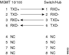
Figure D-2 shows a schematic of the 10/100BASE-T cable required to connect the management port to a switch or hub (not provided with switch).
Figure D-2 Twisted-Pair 10/100BASE-T Cable Schematic
SFP Transceiver Specifications
The Cisco MDS 9216 Switch is compatible with SFP transceivers and cables that have LC connectors. Each transceiver must match the transceiver on the other end of the cable in terms of wavelength, and the cable must not exceed the stipulated cable length for reliable communications.
Cisco SFP transceivers provide the uplink interfaces, laser transmit (TX), and laser receive (RX), and support 850- to 1610-nm nominal wavelengths, depending upon the transceiver.
Use only Cisco SFP transceivers on the Cisco MDS 9216 Switch. Each Cisco SFP transceiver is encoded with model information that enables the switch to verify that the SFP transceiver meets the requirements for the switch. Refer to the Cisco MDS 9000 Family Release Notes for Cisco MDS SAN-OS for your software release to get the list of supported SFP transceivers.
This section provides the following information:
•
•
•
For information about safety, regulatory, and standards compliance, refer to the Regulatory Compliance and Safety Information for the Cisco MDS 9000 Family.
Cisco Fibre Channel SFP Transceivers
Table D-7 lists the Fibre Channel SFP transceivers available through Cisco.
General Specifications for Cisco Fibre Channel SFP Transceivers
Table D-8 lists general specifications for Cisco Fibre Channel SFP transceivers.
Note
.
Table D-8 General Specifications for Cisco Fibre Channel SFP Transceivers
Connector type
LC
LC
Wavelength
850 nm
1310 nm
Fiber type
MMF
SMF
Core size
50 microns
62.5 microns
9/125 microns
Cable distance1
300 m
150 m
10 km
Transmit power
-10 to -1.5 dBm
-9.5 to -3 dBm
1 Approximate; actual distance may vary depending on fiber quality and other factors.
Environmental and Electrical Specifications for Cisco Fibre Channel SFP Transceivers
Table D-9 provides the maximum environmental and electrical ratings for Cisco Fibre Channel SFP transceivers.
Notes:
1.
2.
Cisco Gigabit Ethernet/Fibre Channel Transceivers
Table D-10 lists the combination Gigabit Ethernet/Fibre Channel SFP transceivers available through Cisco.
General Specifications for Cisco Gigabit Ethernet/Fibre Channel SFP Transceivers
Table D-11 lists general specifications for Cisco combination Gigabit Ethernet/Fibre Channel SFP transceivers.
Note
Table D-11 General Specifications for Cisco Gigabit Ethernet/Fibre Channel SFP Transceivers
Connector type
LC
LC
Wavelength
850 nm
1310 nm
Fiber type
MMF
SMF
Core size
50 microns
62.5 microns
9/125 microns
Cable distance1
300 m
150 m
10 km
Transmit power
-1.5 to -9.5 dBm
-3 to -9.5 dBm
1 Approximate; actual distance may vary depending on fiber quality and other factors.
Environmental and Electrical Specifications for Cisco Gigabit Ethernet/Fibre Channel SFP Transceivers
Table D-12 provides the maximum environmental and electrical ratings for Cisco Gigabit Ethernet/Fibre Channel SFP transceivers.
1 Absolute maximum ratings are those values beyond which damage to the device may occur if these limits are exceeded for other than a short period of time.
2 Functional performance is not intended between absolute maximum ratings and the recommended operating conditions. Device reliability is not implied, and damage to the device may occur over an extended period of time.
Cisco CWDM SFP Transceivers
Table D-13 lists the CWDM SFP transceivers available through Cisco.
General Specifications for Cisco CWDM SFP Transceivers
Table D-14 lists general specifications for Cisco CWDM SFP transceivers.
Table D-14 General Specifications for Cisco CWDM SFP Transceivers
Connector type
LC
Wavelength
1470, 1490, 1510, 1530, 1550, 1570, 1590, 1610 nm
Fiber type
SMF
Core size
9/125 microns
Cable distance1
100 km
Transmit power
0 to 5 dBm
Receive sensitivity
-28 to -7 dBm
1 Approximate; actual distance may vary depending on fiber quality and other factors.
Environmental and Electrical Specifications for Cisco CWDM SFP Transceivers
Table D-15 provides the environmental specifications for CWDM SFP transceivers.
Table D-16 provides the electrical specifications for CWDM SFP transceivers.
Optical Specifications for Cisco CWDM SFP Transceivers
Table D-17 provides the optical specifications for CWDM SFP transceivers. CWDM SFP transceivers have an optical link budget of 28 decibels (db).
Note
Note
Cisco Gigabit Ethernet Transceivers
Cisco offers a 1-Gbps Gigabit Ethernet SFP transceiver used on the Cisco MDS 9000 IPS modules.
General Specifications for Cisco Gigabit Ethernet SFP Transceiver
Table D-18 lists general specifications for Cisco Gigabit Ethernet SFP transceiver.
Table D-18 General Specifications for Cisco Gigabit Ethernet SFP Transceivers
Connector type
RJ-45
Fiber type
Copper
Cable distance1
Cu GE is 100 m (328.08 ft)
1 Cat5cable
Environmental and Electrical Specifications for Cisco Gigabit Ethernet SFP Transceiver
Table D-19 provides the maximum environmental and electrical ratings for Cisco Gigabit Ethernet SFP transceiver.
Table D-19 Environmental and Electrical Ratings
Storage temperature
TS
-40
85
°C
1
Case temperature
TC
0
70
°C
1, 2
Relative humidity
RH
95
%
1
Module supply voltage
VCCT,R
3.135V
3.465V
V
1
1 We recommend you do not operate outside the recommended operating conditions. Device reliability may be affected and damage to the device may occur over an extended period of time
2 Absolute maximum ratings are those values beyond which damage to the device may occur if these limits are exceeded for other than a short period of time.