Feedback
Table Of Contents
Cisco MDS 9216 Integrated Supervisor Module
LEDs on the Cisco MDS 9216 Switch Integrated Supervisor Module
16-Port 1-Gbps/2-Gbps Fibre Channel Switching Module
32-Port 1-Gbps/2-Gbps Fibre Channel Switching Module
14/2-Port Multiprotocol Services Module
LEDs on the 14/2-Port Multiprotocol Services Module
LEDs on IP Storage Services Modules
32-Port Fibre Channel Advanced Services Module
LEDs on the Fibre Channel Advanced Services Modules
32-Port Fibre Channel Storage Services Module
LEDs on the Storage Services Modules
LEDs on the Caching Services Module
Fibre Channel SFP Transceivers
Combination Fibre Channel/Gigabit Ethernet SFP Transceivers
CWDM Combination Fibre Channel/Gigabit Ethernet SFP Transceivers
Gigabit Ethernet SFP Transceivers
Product Overview
The Cisco MDS 9216 multilayer fabric switch supports storage area network (SAN) applications. It provides scalability, multi-transport capability, security, and manageability to enterprise SANs. The Cisco MDS 9216 Switch shares a consistent architecture with the Cisco MDS 9500 Series of multilayer directors, making it an intelligent and flexible fabric switch series.
The Cisco MDS 9216 Switch provides the following features:
•
An interface module providing local and remote management interfaces for the supervisor module.
•
•
•
•
•
•
The Cisco MDS 9216 Switch includes a nonremovable supervisor module with an integrated 16-port Fibre Channel switching module. The integrated supervisor module provides switching and local and remote management.
For information about how to configure the Cisco MDS 9216 Switch, refer to http://www.cisco.com/univercd/cc/td/doc/product/sn5000/mds9000/index.htm for the current Cisco MDS 9000 Family configuration guides.
The following hot-swappable, field-replaceable modules are supported by the Cisco MDS 9216 Switch:
•
•
•
•
•
•
•
•
This chapter includes the following information:
•
Chassis
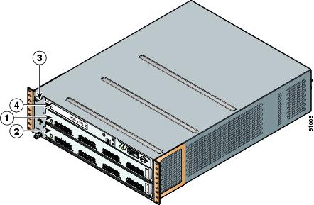
The Cisco MDS 9216 Switch has a two-slot chassis . The Cisco MDS 9216 Switch (see Figure 1-1) has a nonremovable supervisor module (in slot 1) with an integrated 16-port Fibre Channel switching module. See the "Cisco MDS 9216 Integrated Supervisor Module" section.
Figure 1-1 Cisco MDS 9216 Chassis.
Supervisor module with integrated 16-port Fibre Channel switching module
Fan module
Switching module or services module (such as the IPS module)
Interface module
The Cisco MDS 9216 Switch supports the following additional modules:
•
•
•
•
Cisco MDS 9216 Integrated Supervisor Module
The nonremovable Cisco MDS 9216 integrated supervisor module provides the control and management functions for the Cisco MDS 9216 Switch, and it includes an integrated 16-port switching module. The Cisco MDS 9216 integrated supervisor module provides multiple communication and control paths to avoid a single point of failure.
Note
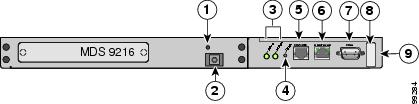
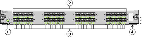
Figure 1-2 shows a Cisco MDS 9216 supervisor module.
Figure 1-2 Cisco MDS 9216 Supervisor Module with Integrated 16-Port Switching Module
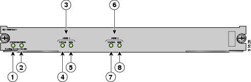
Status LED
Link LEDs (under ports, on left) and Speed LEDs (under ports, on right)
1-Gbps/2-Gbps Fibre Channel ports
Asset tag
The Cisco MDS 9216 integrated supervisor module has a Pentium III class processor, 1 GB of DRAM, and an internal CompactFlash card that provides 256 MB of storage for software images.
LEDs on the Cisco MDS 9216 Switch Integrated Supervisor Module
Table 1-1 describes the LEDs for the Cisco MDS 9216 Switch integrated supervisor module.
Interface Module
The nonremovable interface module is located above slot 1 (see Figure 1-3). It provides the following local and remote management interfaces:
•
–
–
–
•
•
Figure 1-3 Interface Module for the Cisco MDS 9216 Switch
The clock module is also part of the interface module.
Note
LEDs on the Interface Module
Table 1-2 describes the LEDs for the Cisco MDS 9216 Switch interface module.
Switching Modules
The Cisco MDS 9216 Switch supports the following hot-swappable Fibre Channel switching modules:
•
•
The Cisco MDS 9216 Switch supports one hot-swappable switching or services module in addition to the integrated module that is part of the supervisor module.
The Fibre Channel switching modules provide system-wide power management and autonegotiation, which allows ports to negotiate for speed at the other end of the link. Each module has temperature sensors and an EEPROM that stores serial number and model number information.
The Fibre Channel port interfaces support hot-swappable Fibre Channel SFP transceivers, that can be short wavelength (SWL) or long wavelength (LWL). The port interfaces also support coarse wavelength-division multiplexing (CWDM) SFP transceivers, which can be used for extended long wavelength (ELWL) transmission or for CWDM. See "Supported SFP Transceivers" section.
Note
16-Port 1-Gbps/2-Gbps Fibre Channel Switching Module
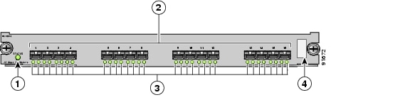
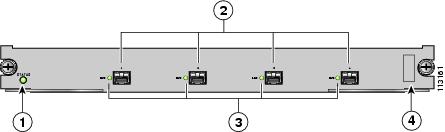
The 16-port 1-Gbps/2-Gbps switching module is best used for applications requiring high bandwidth; for example, Inter-Switch Link (ISL) connections between switches and high-performance host or storage controllers. The 16-port switching module supports a sustained data rate of up to 2 Gbps in each direction, on all ports simultaneously. Figure 1-4 shows a 16-port 1-Gbps/2-Gbps switching module.
The autosensing 1-Gbps/2-Gbps ports of the 16-port Fibre Channel switching module deliver up to 64 Gbps of continuous, aggregate bandwidth when attached to high performance servers and storage subsystems.
Figure 1-4 Cisco MDS 9000 Family 16-Port 1-Gbps/2-Gbps Switching Module
Status LED
Link LED (to left of port) and
Speed LED (to right of port)1-Gbps/2-Gbps Fibre Channel ports
Asset tag
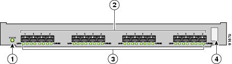
32-Port 1-Gbps/2-Gbps Fibre Channel Switching Module
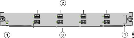
The 32-port 1-Gbps/2-Gbps Fibre Channel switching module can be used to allocate bandwidth optimally, and it delivers the industry's highest linecard port density. The module is organized into eight four-port groups. Only the first port in each four-port group can be an ISL. If the first port is an ISL, the other three ports in the group are disabled. The four ports within a port group share a single internal channel resulting in a subscription ratio of approximately 3.2:1. The 32-port 1-Gbps/2-Gbps switching module provides more ports at a lower price per port. Figure 1-5 shows a 32-port switching module.
Tip
Figure 1-5 Cisco MDS 9000 Family 32-Port 1-Gbps/2-Gbps Switching Module
Status LED
Link LED (to left of port) and
Speed LED (to right of port)1-Gbps/2-Gbps Fibre Channel port group
Asset tag
Switching Module Features
Each switching module draws its power from the 42 V supplied on the backplane with local DC/DC power converters and regulators.
The control processor on the switching module provides power-on, offline, and online diagnostics. The control processor can be used to configure devices on the switching module and to gather statistical data from each port.
The control processor can determine which slot it is plugged into, and it can monitor its DC/DC power source and temperature. The control processor signals the supervisor module and displays an alarm on its front panel when a problem is detected.
The front panel on the switching module provides basic status information, such as power-on, self-test running, self-test passed, alarm, and ready.
The binary image for the switching module is downloaded from the supervisor module. Prior to the image download, the control processor on the switching module runs from code stored on its local CompactFlash card.
Note
The integrated supervisor module can force a reset on the switching module and controls whether power is applied to the switching module.
If a single component or a set of components on the switching module fails, this does not disable other switching modules if that is the only failure in the system.
Each switching module has a hardware watchdog timer to detect most component failures. The watchdog timer resets the card if it is not serviced periodically.
LEDs on the Switching Modules
Table 1-3 describes the LEDs for the 16-port and 32-port switching modules.
Table 1-3 LEDs for the Cisco MDS 9000 Family Fibre Channel Switching Modules
Status
Green
All diagnostics pass. The module is operational (normal initialization sequence).
Orange
The module is booting or running diagnostics (normal initialization sequence).
or
The inlet air temperature of the system exceeded the maximum system operating temperature limit (a minor environmental warning). To ensure maximum product life, you should immediately correct the environmental temperature and restore the system to normal operation.
Red
The diagnostic test failed. The module is not operational because a fault occurred during the initialization sequence.
or
The inlet air temperature of the system exceeded the safe operating temperature limits of the card (a major environmental warning). The card shut down to prevent permanent damage.
Speed
On
2-Gbps mode.
Off
1-Gbps mode.
Link
Solid green
Link is up.
Steady flashing green
Link is up (beacon used to identify port).1
Intermittent flashing green
Link is up (traffic on port).
Solid yellow
Link is disabled by software.
Flashing yellow
A fault condition exists.
Off
No link.
1 The flashing green light turns on automatically when an external loopback is detected that causes the interfaces to be isolated. The flashing green light overrides the beacon mode configuration. The state of the LED is restored to reflect the beacon mode configuration after the external loopback is removed.
The Fibre Channel switching modules provide auto-configuring Fibre Channel ports that support Fibre Channel speeds of 1.0625 Gbps and 2.125 Gbps. For more information about supported port types, refer to http://www.cisco.com/univercd/cc/td/doc/product/sn5000/mds9000/index.htm for the latest Cisco MDS 9000 Family configuration guides.
Services Modules
The Cisco MDS 9216 Switch supports the following hot-swappable sevices modules:
•
•
•
The Cisco MDS 9216 Switch supports one hot-swappable switching or services module in addition to the integrated module that is part of the supervisor module. Each module has temperature sensors and an EEPROM that stores serial number and model number information.
Note
14/2-Port Multiprotocol Services Module
The 14/2-port Multiprotocol Services (MPS-14/2) module provides 14 1-Gbps/2-Gbps Fibre Channel auto-sensing ports and two 1-Gigabit Ethernet ports for iSCSI and FCIP over Gigabit Ethernet. The MPS-14/2 module supports the intelligent features available on other modules, including VSANs, security, and traffic management.
The 14 1-Gbps/2-Gbps auto-sensing FC ports (labeled 1 through 14) are best used for applications requiring high bandwidth; for example, Inter-Switch Link (ISL) connections between switches and high-performance host or storage controllers. Each FC port supports a sustained data rate of up to 2 Gbps in each direction.
The Cisco MDS 9216 Switch supports one MPS-14/2 module. The two Gigabit Ethernet ports(labeled 1 and 2) provide 1-Gbps throughput for IP services, including iSCSI and FCIP over Gigabit Ethernet. The MPS-14/2 also supports hardware-based encryption and compression for these Gigabit Ethernet ports. This hardware-based encryption handles the computationally intensive IPsec feature for IP services.
The MPS-14/2 modules support FCIP compression to maximize the effective WAN bandwidth of SAN extension solutions. It achieves up to a 30 to 1 compression ratio, with typical ratios of 2 to 1 over a wide variety of data sources. With the addition of hardware-based compression, the MPS-14/2 module is able to provide optimal levels of compressed throughput for implementations across low to high-bandwidth links.
The Gigabit Ethernet ports on the MPS-14/2 module support iSCSI protocol, FCIP protocol, or both protocols simultaneously. For information about configuring the ports, refer to the Cisco MDS 9000 Family Configuration Guide.
The Fibre Channel port interfaces support hot-swappable Fibre Channel SFP transceivers, which can be short wavelength (SWL) for connectivity up to 500 meters, or long wavelength (LWL) for connectivity up to 10 km. All interfaces are autosensing 1-Gbps or 2-Gbps compatible. The port interfaces also support coarse wavelength-division multiplexing (CWDM) SFP transceivers, which can be used for extended long wavelength (ELWL) transmission or for coarse wavelength-division multiplexing (CWDM). See "Supported SFP Transceivers" section.
Note
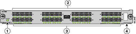
Figure 1-6 shows an MPS-14/2 module.
Figure 1-6 MPS-14/2 Module
Status LED
Gigabit Ethernet ports
1-Gbps/2-Gbps Fibre Channel ports
Link LEDs
Link LEDs (under ports, on left) and Speed LEDs (under ports, on right)
Asset tag
LEDs on the 14/2-Port Multiprotocol Services Module
Table 1-4 describes the LEDs for the MPS-14/2 modules.
IP Storage Services Modules
The 4-port and 8-port IP Storage services (IPS-4 and IPS-8) modules provide four or eight 1-Gigabit Ethernet ports for iSCSI as well as FCIP over Gigabit Ethernet, and they support the intelligent features available on other modules, including VSANs, security, and traffic management.
The IPS module ports can be configured to support iSCSI protocol, FCIP protocol, or both protocols simultaneously. For information about configuring the ports, refer to the Cisco MDS 9000 Family Configuration Guide.
The Fibre Channel port interfaces support hot-swappable Fibre Channel SFP transceivers, which can be short wavelength (SWL) for connectivity up to 500 meters, or long wavelength (LWL) for connectivity up to 10 km. The port interfaces also support coarse wavelength-division multiplexing (CWDM) SFP transceivers, which can be used for extended long wavelength (ELWL) transmission or for coarse wavelength-division multiplexing (CWDM). See "Supported SFP Transceivers" section.
Figure 1-7 shows a 4-port IPS module.
Figure 1-7 Cisco MDS 9000 Family 4-Port IP Storage Services Module
Figure 1-8 shows an 8-port IPS module.
Figure 1-8 Cisco MDS 9000 Family 8-Port IP Storage Services Module
LEDs on IP Storage Services Modules
Table 1-5 describes the LEDs for the IPS module.
32-Port Fibre Channel Advanced Services Module
The Cisco MDS 9000 Family 32-port Fibre Channel Advanced Services Module (ASM) enables pooling of heterogeneous storage for increased storage utilization, simplified storage management, and reduced total cost of storage ownership. The Advanced Services Module incorporates all the capabilities of the Cisco MDS 9000 DS-X9032 Fibre Channel switching module and also provides scalable, in-band storage virtualization services. The module makes it possible to allocate bandwidth optimally and delivers the industry's highest line-card port density.
The Fibre Channel port interfaces support hot-swappable Fibre Channel SFP transceivers, which can be short wavelength (SWL) for connectivity up to 500 meters, or long wavelength (LWL) for connectivity up to 10 km. All interfaces are autosensing 1-Gbps or 2-Gbps compatible. The port interfaces also support coarse wavelength-division multiplexing (CWDM) SFP transceivers, which can be used for extended long wavelength (ELWL) transmission or for coarse wavelength-division multiplexing (CWDM). See "Supported SFP Transceivers" section.
Figure 1-9 shows the Fibre Channel Advanced Services Module.
Figure 1-9 Fibre Channel Advanced Services Module
Each module draws power from the 42 V supplied on the backplane with local DC/DC power converters and regulators.
The control processor on the module provides power-on, offline, and online diagnostics. The control processor can be used to configure devices on the switching module and to gather statistical data from each port.
The control processor monitors the DC/DC power source and temperature. The control processor signals the supervisor module and displays an alarm on its front panel when a problem is detected.
The front panel on the services module provides basic status information, such as power-on, self-test running, self-test passed, alarm, and ready.
The binary image for the services module is downloaded from the supervisor module. Prior to the image download, the control processor on the switching module runs from code stored on its local CompactFlash card.The image for an ASM-SFN can be specified using the ASM-SFN boot variable. For details on how to specify the SSI boot variable, refer to the Cisco MDS 9000 Family Configuration Guide.
Note
The supervisor module can force a reset on the services module and controls whether power is applied to the switching module.
If a single component or a set of components on the switching module fails, this failure does not disable another switching module if that is the only failure in the system.
Each ASM has a hardware watchdog timer to detect most component failures. The watchdog timer resets the card if is not serviced periodically.
LEDs on the Fibre Channel Advanced Services Modules
Table 1-6 describes the LEDs for the ASM.
32-Port Fibre Channel Storage Services Module
The 32-port Fibre Channel Storage Services Module (SSM) for the Cisco MDS 9000 Family supports up to 32 Fibre Channel ports, provides distributed intelligent storage services, and supports future storage services.
Note
The Fibre Channel ports support hot-swappable Fibre Channel SFP transceivers, which can be short wavelength (SWL) for connectivity up to 500 m, or long wavelength (LWL) for connectivity up to 10 km. All interfaces are autosensing 1-Gbps/2-Gbps compatible. The ports also support coarse wavelength-division multiplexing (CWDM) SFP transceivers, which can be used for extended long wavelength (EWL) transmission or for CWDM. For more information about SFP transceivers, see the "Supported SFP Transceivers" section.
Figure 1-10 shows the SSM.
Figure 1-10
Cisco MDS 9000 Family Storage Services Module
Each module draws power from the 42 V supplied on the backplane with local DC/DC power converters and regulators.
The control processor on the module provides power-on, offline, and online diagnostics. The control processor can be used to configure devices on the switching module and to gather statistical data from each port.
The control processor monitors the DC/DC power source and temperature. The control processor signals the supervisor module and displays an alarm on its front panel when it detects a problem.
The front panel on the services module provides basic status information, such as power-on, self-test running, self-test passed, alarm, and ready.
The binary image for the services module is downloaded from the supervisor module. Prior to the image download, the control processor on the services module runs from code stored on its local CompactFlash card. The image for an SSM can be specified using the SSI boot variable. For details on how to specify the SSI boot variable, refer to the Cisco MDS 9000 Family Configuration Guide.
Note
The supervisor module can force a reset on the services module and controls whether or not power is applied to the switching module.
If a single component or a set of components on the switching module fails, this failure will not disable another switching module if that is the only failure in the system.
For the detection of most component failures, each switching module has a hardware watchdog timer that resets the card if is not serviced periodically.
LEDs on the Storage Services Modules
Table 1-7 describes the LEDs for the Storage Services Module.
Caching Services Module
The Caching Services Module (CSM) provides virtualization services that allow the Cisco MDS 9000 Family switches to reallocate physical resources as virtual resources for increased efficiency. The CSM receives and sends data through the switch backplane. It has two disk drives, two internal batteries for backup in case of power failure, and no external ports.
CSMs must be implemented in pairs in the fabric to provide redundancy and backup. Only two or more CSMs in a fabric are supported. However, the CSMs do not have to be installed in the same switch.
The CSM may shut down due to the software, an external power failure occurred, or the module separated from the backplane while it still had power. The CSM automatically backs up the data in memory to the disk drives and then shuts down. The CSM batteries provide adequate power to back up data without external power.
Figure 1-11 shows the faceplate of the CSM.
Figure 1-11 CSM
Status LED
Disk 1 Status LED
Battery LED
Node 2 LEDs
Node 1 LEDs
Node 2 Status LED
Node 1 Status LED
Disk 2 Status LED
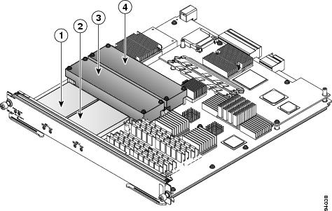
Figure 1-12 shows the location of the disk drives and batteries on the CSM.
Caution
Figure 1-12 CSM, Internal View
See the "Removing and Installing Switching and Services Modules" section for information about removing and installing the CSM and maintaining the CSM batteries.
LEDs on the Caching Services Module
Table 1-8 describes the LEDs for the CSM.
Power Supplies
The Cisco MDS 9216 Switch supports dual hot-swappable 845-W AC power supplies, each of which can supply sufficient power to the entire chassis should one power supply fail. The power supplies monitor their output voltage and provide status to the supervisor module. To prevent the unexpected shutdown of an optional module, power management software only allows a module to power up if adequate power is available.
The Cisco MDS 9216 Switch power supplies can be configured to be redundant or combined. By default, they are configured as redundant, so that if one fails, the remaining power supply can still power the entire system. For information on how to configure the power supplies, refer to the Cisco MDS 9000 Family Configuration Guide.
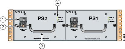
The power supplies, which are accessed from the rear of the chassis, are illustrated in Figure 1-13.
Figure 1-13 Cisco MDS 9216 Switch with 845-W Dual Power Supplies
Table 1-9 describes the LEDs for the Cisco MDS 9216 Switch power supplies.
Fan Modules
The Cisco MDS 9216 Switch supports a hot-swappable fan module with four fans. The fan module provides 80 cfm (cubic feet per minute) of cooling per slot, allowing 400 W of power dissipation per slot. Sensors on the supervisor module monitor the internal air temperature. If the air temperature exceeds a preset lower-level threshold, the environmental monitor displays warning messages. If the air temperatures exceeds a preset higher-level threshold, the switch is shut down.
If one or more fans within the fan module fail, the Fan Status LED turns red. Individual fans cannot be replaced, you must replace the entire fan module.If the higher-level temperature threshold is not exceeded, the switch continues to run for five minutes after the fan module is removed. This means you can swap out a fan module without having to bring the system down. To replace a fan module, see the "Removing and Installing the Fan Module" section. The fan module has one Status LED, that indicates the following conditions:
•
•
•
Caution
Supported SFP Transceivers
The following types of SFP transceivers are available from Cisco and are supported on the Cisco MDS 9216 Switch:
•
•
•
•
SFP transceivers are field-replaceable. You can use any combination of SFP transceivers that are supported by the switch. The only restrictions are that SWL transceivers must be paired with SWL transceivers, LWL transceivers with LWL transceivers, and the cable must not exceed the stipulated cable length for reliable communications.
Refer to http://www.cisco.com/univercd/cc/td/doc/product/sn5000/mds9000/index.htm for the Cisco MDS 9000 Family Release Notes for Cisco MDS SAN-OS Release for your software release to get the list of supported SFP transceivers. For more information about a specific Cisco SFP transceiver, see the "SFP Transceiver Specifications" section.
SFP transceivers can be ordered separately or with the Cisco MDS 9216 Switch.
Note
Fibre Channel SFP Transceivers
The Cisco Fibre Channel SFP transceivers are available in short wavelength (SWL) or long wavelength (LWL) versions. Both of these versions are 1-Gbps and 2-Gbps capable.
The Cisco Fibre Channel SFP transceivers have LC connectors and comply with
1-Gbps and 2-Gbps Fibre Channel standards as defined in FC-PI 10.0 2.Transmission ranges for 2 Gbps are as follows:
•
•
•
For detailed transceiver specifications, see "SFP Transceiver Specifications" section.
Combination Fibre Channel/Gigabit Ethernet SFP Transceivers
The Cisco combination Fibre Channel/Gigabit Ethernet SFP transceivers are available in short wavelength (SWL) or long wavelength (LWL) versions. Both of these versions are 1-Gbps and 2-Gbps capable.
The Cisco combination SFP transceivers have LC connectors and comply with 1-Gbps and 2-Gbps Fibre Channel as defined in FC-PI 10.0 2 and Gigabit Ethernet as defined in IEEE 802.3z.
Transmission ranges are as follows:
•
•
•
See the "SFP Transceiver Specifications" section.
CWDM Combination Fibre Channel/Gigabit Ethernet SFP Transceivers
All Fibre Channel and Gigabit Ethernet ports in the Cisco MDS 9216 Switch support CWDM SFP transceivers.
The Cisco CWDM SFP transceivers have LC connectors and support both Gigabit Ethernet and Fibre Channel (1-Gbps and 2-Gbps). They match the wavelength plan of Cisco CWDM GBICs and Cisco CWDM optical add/drop multiplexers (OADMs).
CWDM SFP transceivers can be used in two ways:
•
•
There are eight different "colors" of CWDM SFP transceivers, one for each fixed wavelength. The fiber optic cables from the CWDM SFP transceivers must be connected to an OADM. The OADM combines the wavelengths of the different outgoing signals into one composite send signal. The OADM also separates the received transmissions into the different wavelengths and sends them to the corresponding CWDM SFP transceiver.
See the "SFP Transceiver Specifications" section.
Gigabit Ethernet SFP Transceivers
The 4-port and 8-port IP Storage services (IPS-4 and IPS-8) modules provide four or eight 1-Gigabit Ethernet ports that support Gigabit Ethernet SFP transceivers. The Gigabit Ethernet SFP transceivers have RJ-45 connectors and support Gigabit Ethernet (1-Gbps).
For detailed transceiver specifications, see the "SFP Transceiver Specifications" section.