Feedback
Table Of Contents
Cisco MDS 9100 Series Multilayer Fabric Switches
Cisco MDS Fibre Channel Bladeswitch for IBM BladeCenter
Ports on the Cisco MDS 9134 Switch
Ports on the Cisco MDS 9124 Switch
Ports on the Cisco MDS 9140 Switch and the Cisco MDS 9120 Switch
Fibre Channel SFP Transceivers
Combination Fibre Channel/Gigabit Ethernet SFP Transceivers
CWDM Combination Fibre Channel/Gigabit Ethernet SFP Transceivers
Product Overview
The Cisco MDS 9100 Series Multilayer Fabric Switches provide an intelligent, cost-effective, and small-profile switching platform for small- and medium-sized storage environments. The Cisco MDS 9100 Series also provides full-feature capability with the Cisco MDS 9500 Series multilayer directors for a transparent, end-to-end service delivery in large data-center core-edge deployments.
The Cisco MDS 9100 Series includes four fixed configuration fabric switches:
•
The Cisco MDS 9134 Multilayer Fabric Switch is a 32-port 1-, 2-, and 4-Gbps autosensing Fibre Channel and 2-port 10-Gbps switch.
•
•
•
The Cisco MDS 9100 Series is packaged in compact 1-RU enclosures with redundant hot-swappable power supplies. The Cisco MDS 9140 Switch and the Cisco MDS 9120 Switch also include two hot-swappable fan modules. Management access is provided through 10/100 Ethernet and serial console interfaces.
The Cisco MDS 9100 Series provides the following features:
•
•
•
•
•
•
•
The Cisco MDS 9134 Multilayer Fabric Switch and the Cisco MDS 9124 Multilayer Fabric Switch also provide the following features:
•
•
•
•
For a list of features supported on the Cisco MDS 9134 Switch and the Cisco MDS 9124 Switch and for information on how to configure the Cisco MDS 9100 Series, see the Cisco MDS 9000 Family Fabric Manager Configuration Guide and the Cisco MDS 9000 Family CLI Configuration Guide.
This chapter describes hardware information about the Cisco MDS 9100 Series and its components, and it includes the following sections:
•
•
Cisco MDS 9100 Series Multilayer Fabric Switches
This section describes the four Cisco MDS 9100 Series configurations:
Cisco MDS 9134 Switch
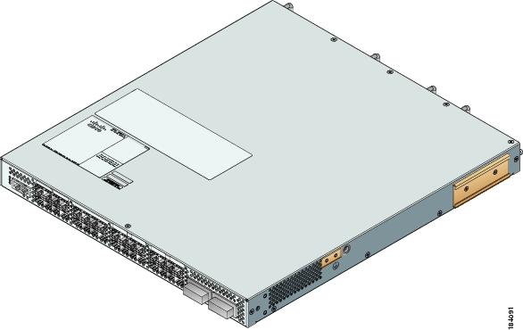
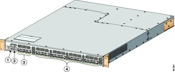
The Cisco MDS 9134 Multilayer Fabric Switch has a total of 32 1-, 2-, and 4-Gbps autosensing Fibre Channel ports, and 2 10-Gbps ports. The Cisco MDS 9134 Switch (see Figure 1-1) features On-Demand Port activation licensing. By default, the first 24 ports are licensed. An additional license is required for the remaining 8 ports. The 2 10-Gbps ports are not licensed by default. They require a separate license.
Two Cisco MDS 9134 Switches can be stacked by using copper CX4 X2 transceivers. By means of the stacked switch configuration, two Cisco MDS 9134 Switches enable 48 ports and/or 64 ports. For information on stacked switch installation, see Installing Cisco MDS 9134 48-Port and 64-Port Stackable Bundles, page 2-21.
Cisco MDS 9134 Multilayer Fabric Switch supports N port identifier virtualization (NPIV). NPIV can assign multiple FC IDs to a single N port. This feature allows multiple applications on the N port to use different identifiers and allows access control, zoning, and port security at the application level. For a list of features supported on the Cisco MDS 9124 Switch, see the Cisco MDS 9000 Family Fabric Manager Configuration Guide and the Cisco MDS 9000 Family CLI Configuration Guide.
Figure 1-1 Cisco MDS 9134 Switch
Cisco MDS 9124 Switch
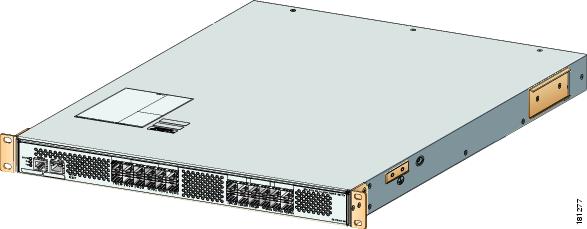
The Cisco MDS 9124 Multilayer Fabric Switch has a total of 24 1-, 2-, and 4-Gbps autosensing Fibre Channel ports. The Cisco MDS 9124 Switch features On-Demand Port Licensing. You can activate licensing in 8-port increments with each on-demand port activation license for up to a total of 24 ports. By default, the first 8 ports are licensed. Two additional licenses are required to license all 24 ports. See Figure 1-2.
Figure 1-2 Cisco MDS 9124 Switch
Cisco MDS 9124 Multilayer Fabric Switch supports N port identifier virtualization (NPIV). NPIV can assign multiple FC IDs to a single N port. This feature allows multiple applications on the N port to use different identifiers and allows access control, zoning, and port security at the application level
For a list of features supported on the Cisco MDS 9124 Switch, see the Cisco MDS 9000 Family Fabric Manager Configuration Guide and the Cisco MDS 9000 Family CLI Configuration Guide.
Cisco MDS 9140 Switch
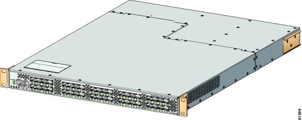
The Cisco MDS 9140 Switch has a total of 40 1/2-Gbps autosensing, optionally configurable ports. The first eight ports on the left-hand side are the bandwidth-optimized ports. They are delineated by a white border. The remaining eight groups of four ports each are the host optimized port groups. See Figure 1-3.
Figure 1-3 Cisco MDS 9140 Switch
Cisco MDS 9120 Switch
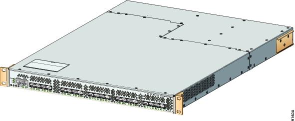
The Cisco MDS 9120 Switch has a total of 20 1/2-Gbps autosensing, optionally configurable ports. The first group of four ports on the left-hand side are the bandwidth-optimized ports. They are delineated by a white border. The remaining four groups of four ports each are the host optimized port groups. See Figure 1-4.
Figure 1-4 Cisco MDS 9120 Switch
Cisco MDS Fibre Channel Bladeswitch for IBM BladeCenter
The Cisco MDS Fibre Channel Bladeswitch for IBM BladeCenter is designed for IBM BladeCenter environments. The Cisco MDS Fibre Channel Bladeswitch is based on the Cisco MDS 9000 Family SAN switching technology, which integrates the Cisco MDS 9000 Family of switches and directors into a blade-switch architecture. The advanced architecture of the Cisco MDS Fibre Channel Bladeswitch for IBM BladeCenter, along with 4-GB technology, provides outstanding performance between Bladeswitches and the rest of the Fibre Channel infrastructure.
The Cisco MDS Fibre Channel Bladeswitch for IBM BladeCenter provides 4-GB Fibre Channel performance to blade-server switching. It also provides network intelligence features such as virtual SANs (VSANs), quality of service (QoS), and N-port interface virtualization (NPIV). It also offers nondisruptive software upgrades and on-demand port activation and is the most complete embedded Fibre Channel switching available for the IBM BladeCenter, BladeCenter-T, and BladeCenter-H platforms.
The Cisco MDS Fibre Channel Bladeswitch for IBM BladeCenter provides up to 20 nonblocking 1-, 2-, and 4-GB Fibre Channel ports that are available in two configurations: 7 internal ports and 3 external ports, or 14 internal ports and 6 external ports. Each port provides line-rate performance up to 4-GB without any performance loss for integrated features such as VSANs, QoS, or Network Address Translation (NAT). The Cisco MDS Fibre Channel Bladeswitch for IBM BladeCenter supports up to 16 VSANs per blade switch.
Each external port on the Cisco MDS FC Bladeswitch for IBM BladeCenter also provides line-rate performance up to 4-GB for Inter-Switch Links (ISLs) or additional device connectivity such as storage or host bus adapters (HBAs).
The Cisco SAN-OS software provides role-based access control (RBAC) for management access of the Cisco Fibre Channel Bladeswitch for IBM BladeCenter command-line interface (CLI) and Simple Network Management Protocol (SNMP). For more information, see the Cisco 9000 Family Command Reference.
Power Supplies
The Cisco MDS 9100 Series supports dual AC power supplies. Each power supply provides sufficient power to maintain switch operation in the event of a single power supply failure. Power supplies are hot swappable and can be individually replaced without disruption to the system. (See the "Power Specifications" section on page B-2.)
Caution
The power supply has two LEDs, AC ok and DC ok. Power supply status is also indicated on a front panel LED.
Procedures for replacing and installing the power supplies are available in the "Removing and Installing Components" section on page 2-26.
The Cisco MDS 9124 Switch includes a front panel reset button that resets the switch without cycling the power.
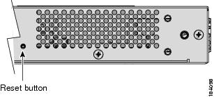
The Cisco MDS 9134 Switch includes a reset button on the left side of the switch as shown in Figure 1-5.
Figure 1-5 Reset Button on the Side of the Cisco MDS 9134 Switch
Fan Modules
The Cisco MDS 9140 Switch, the Cisco MDS 9134 Switch, and the Cisco MDS 9120 Switch support two hot-swappable fan modules that allow the switches to continue to run if a fan module is removed, provided that the preset temperature thresholds have not been exceeded. You can swap out a fan module without having to bring the system down. Each fan module on the Cisco MDS 9134 Switch has two fans. The Cisco MDS 9124 Switch includes three fixed fans and an additional fan in each removable power supply. For normal operation, the Cisco MDS 9124 Switch requires four fans.
Caution
Except for the Cisco MDS 9134 Switch, the fan modules each have one Status LED. The Cisco MDS 9134 Switch fan modules do not have a Status LED. Fan module status is also indicated on a front panel LED.
Procedures for replacing and installing the fan modules are available in the "Removing and Installing Components" section on page 2-26.
Cisco MDS 9100 Series Ports
The Cisco MDS 9100 Series provides host, target, and Inter-Switch Link (ISL) connectivity.
Ports on the Cisco MDS 9134 Switch
The Cisco MDS 9134 Switch provides up to 32 autosensing and autonegotiating Fibre Channel ports capable of speeds of 1, 2, and 4 Gbps. The first 24 ports are licensed by default. On-Demand Port Activation Licensing allows expansion to 32 ports, with additional ports available as an 8-port group. The Cisco MDS 9134 Switch also offers two 10-Gbps ports. Table 1-1 shows the mapping of ports to port groups.
All 32 4-Gbps ports and 2 10-Gbps ports can operate at line rate concurrently. In addition, the 10-Gbps ports can be activated independently at 24- or 32-port configurations.
A 64-port switch can be formed by stacking two Cisco MDS 9134 Switches together using a copper CX4 X2 transceiver.
The Cisco MDS 9134 Switch includes hot-swappable SFP interfaces. All SFP interfaces are 1, 2, and 4 Gbps, with autosensing capabilities. Individual ports can be configured with either short- or long-wavelength SFP optics for connectivity up to 860 meters and 10 kilometers, respectively. The two 10-Gbps ports support X2 form factor optics, either copper or optical.
For more information about on-demand port licensing, see the Cisco MDS 9000 Family CLI Configuration Guide and the Cisco MDS 9000 Family Fabric Manager Configuration Guide.
Figure 1-6 shows the Cisco MDS 9134 ports.
Figure 1-6 Cisco MDS 9134 Ports
Console port
8 on-demand ports
10/100 Ethernet management port
2 10-Gbps ports
24 default licensed ports
Ports on the Cisco MDS 9124 Switch
The Cisco MDS 9124 Switch has 24 1-, 2-, and 4-Gbps autosensing and autonegotiating Fibre Channel ports with on-demand port activation licensing.
The on-demand ports are licensed in groups of eight. By default, an on-demand license for the first eight ports (ports 1 through 8) is included with the switch. You can transfer that license to other ports on the switch or obtain extra licenses to make more ports on the switch available. You can activate additional ports in 8-port increments with each on-demand port license. To purchase additional on-demand port licenses, contact your customer service representative and refer to Part Number M9124PL8-4G=.
For more information about on-demand port licensing, see the Cisco MDS 9000 Family CLI Configuration Guide and the Cisco MDS 9000 Family Fabric Manager Configuration Guide. See Figure 1-7.
Figure 1-7 Cisco MDS 9124 Ports
Ports on the Cisco MDS 9140 Switch and the Cisco MDS 9120 Switch
On the Cisco MDS 9140 Switch and the Cisco MDS 9120 Switch, bandwidth optimized ports are on the left side of the front panel, surrounded by a white border. These ports are best used for applications requiring very high bandwidth: for example, ISL connections between switches and high-performance host or target controllers. These ports support a sustained data rate of up to 2 Gbps in each direction, on all ports simultaneously.
Host optimized ports are best for all but the most bandwidth intensive connections and are typically used to connect host devices (servers) to the SAN. These ports are organized into four port groups.
The four ports within a port group share access to a single internal channel resulting in a subscription ratio of approximately 3.2:1.
Tip
Only the first port in each four-port group can be an Inter-Switch Link (ISL). If the first port is an ISL, the other three ports in the group are disabled. See Figure 1-8.
Figure 1-8 Cisco MDS 9140 and Cisco MDS 9120 Switch Ports
Console port
Bandwidth optimized switching ports
10/100 Ethernet management port
Host optimized switching port groups
Switch LEDs
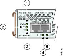
The front panel of the Cisco MDS 9100 Series includes the LEDs shown in Figure 1-9, Figure 1-10, and Figure 1-11. You can use the LEDs on this panel to quickly identify system status.
Figure 1-9 Cisco MDS 9134 Switch LEDs
Switch status LED
10/100 Ethernet management port link LED
Power supply LED
10/100 Ethernet management port activity LED
Fan module status LED
Figure 1-10 Cisco MDS 9124 Switch LEDs
Figure 1-11 Cisco MDS 9140 Switch and Cisco MDS 9120 Switch LEDs
Switch status LED
10/100 Ethernet management port activity LED
Power supply LED
Top port link LED
Fan module status LED
Bottom port link LED
10/100 Ethernet management port link LED
Table 1-2 describes the front panel LEDs for the Cisco MDS 9100 Series.
Table 1-2 Switching Module LEDs
Switch status
Green
All diagnostics pass. The module is operational (normal initialization sequence).
Orange
The module is booting or running diagnostics (normal initialization sequence).
Switch temperature is high. (A minor threshold was exceeded during environmental monitoring.)
Red
The diagnostic test failed. The module is not operational because a fault occurred during the initialization sequence.
Switch overheated. (A major threshold was exceeded during environmental monitoring.)
Power supply status
Green
Both power supplies are working.
Orange
One power supply has failed or has been removed.
Red or all LEDs off
Both power supplies have failed.
Fan module status
Green
Both fan modules are working properly.
Orange
One of the fan modules has failed.
Red
Both fan modules have failed.
Management port link
Intermittent flashing green
Traffic is on the management port.
Management port activity
Green
Management port is active.
Red
Management port is not active.
Port speed
On
2-Gbps mode.
Off
1-Gbps mode.
Port link
Solid green
Link is up.
Steady flashing green
Link is up (beacon used to identify port).1
Intermittent flashing green
Link is up (traffic on port).
Solid orange
Link is disabled by software.
Flashing orange
A fault condition exists.
1 The flashing green light turns on automatically when an external loopback is detected that causes the interfaces to be isolated. The flashing green light overrides the beacon mode configuration. The state of the LED is restored to reflect the beacon mode configuration after the external loopback is removed.
Supported SFP Transceivers
The following types of SFP transceivers are available from Cisco Systems and are supported on the Cisco MDS 9100 Series:
•
•
•
Note
SFP transceivers are field-replaceable. You can use any combination of SFP transceivers that are supported by the switch. The only restrictions are that SWL transceivers must be paired with SWL transceivers, and LWL transceivers with LWL transceivers, and the cable must not exceed the stipulated cable length for reliable communications.
For the list of supported SFP transceivers, see the Cisco MDS 9000 Family Release Notes. For more information about a specific Cisco SFP transceiver, see the "SFP Transceiver Specifications" section on page B-4. SFP transceivers can be ordered separately or with the Cisco MDS 9100 Series.
Note
Fibre Channel SFP Transceivers
Cisco Fibre Channel SFP transceivers are available in SWL or LWL versions. Both versions are 1-Gbps/2-Gbps capable. The Cisco MDS 9124 Switch supports 4-Gbps Fibre Channel SFP transceivers.
Cisco Fibre Channel SFP transceivers have LC connectors and comply with 1-, 2-, and 4 Gbps Fibre Channel standards as defined in FC-PI 10.0 2.
Transmission ranges for 2 Gbps are as follows:
•
•
•
Transmission ranges for 4 Gbps are as follows:
•
•
•
For transceiver specifications, see Appendix C, "Cable and Port Specifications."
Combination Fibre Channel/Gigabit Ethernet SFP Transceivers
The combination Fibre Channel/Gigabit Ethernet SFP transceivers from Cisco Systems are available in SWL or LWL versions for the Cisco MDS 9140 Switch and the Cisco MDS 9120 Switch. Both versions are 1-Gbps and 2-Gbps capable.
The combination SFP transceivers from Cisco Systems have LC connectors and comply with 1-Gbps and 2-Gbps Fibre Channel as defined in FC-PI 10.0 2 and Gigabit Ethernet as defined in IEEE 802.3z.
Transmission ranges are as follows:
•
•
•
For transceiver specifications, see Appendix C, "Cable and Port Specifications."
CWDM Combination Fibre Channel/Gigabit Ethernet SFP Transceivers
All Fibre Channel and Gigabit Ethernet ports in the Cisco MDS 9100 Series support CWDM SFP transceivers.
The Cisco CWDM SFP transceivers have LC connectors and support both Gigabit Ethernet and Fibre Channel (1-Gbps / 2-Gbps). They match the wavelength plan of Cisco CWDM GBICs and Cisco CWDM optical add/drop multiplexers (OADMs).
CWDM SFP transceivers can be used in two ways:
•
•
There are eight different "colors" of CWDM SFP transceivers, one for each fixed wavelength. The fiber optic cables from the CWDM SFP transceivers must be connected to an OADM, which combines the wavelengths of the different outgoing signals into one composite send signal, and separates the received transmissions into the different wavelengths and sends them to the corresponding CWDM SFP transceiver.
For detailed transceiver specifications, see Appendix C, "Cable and Port Specifications."