Feedback
Table Of Contents
Installing the Cisco MDS 9100 Series
Unpacking and Inspecting the Switch
Installing the Switch in a Cabinet or Rack
Installing the Switch in a Cabinet with Insufficient Front Clearance
Installing Front Rack-Mount Brackets for Cabinets with 26 Inches or Greater of Rail Spacings
Installing Front Rack-Mount Brackets for Cabinets with Less Than 26 Inches of Rail Spacings
Installing Cisco MDS 9100 Series Switch Rear-Facing into Cabinet
Installing a Cisco MDS 9134 Switch or a Cisco MDS 9124 Switch Rear-Facing into Cabinet
Installing Cisco MDS 9134 48-Port and 64-Port Stackable Bundles
Removing and Installing Components
Removing and Installing Power Supplies
Removing and Installing Fan Modules
Installing the Cisco MDS 9100 Series
This chapter describes how to install the Cisco MDS 9100 Series and its components, and it includes the following information:
•
Installing the Switch in a Cabinet or Rack
•
•
•
Note
Warning
This warning symbol means danger. You are in a situation that could cause bodily injury. Before you work on any equipment, be aware of the hazards involved with electrical circuitry and be familiar with standard practices for preventing accidents. Use the statement number provided at the end of each warning to locate its translation in the translated safety warnings that accompanied this device. Statement 1071
SAVE THESE INSTRUCTIONS
Warning
Warning
Note
Preinstallation
This section includes the following information:
•
Installation Options
The Cisco MDS 9100 Series can be installed using the following methods:
•
–
–
•
–
–
•
–
For instructions on installing the switch using the rack-mount kit shipped with the switch, see the"Installing the Switch in a Cabinet or Rack" section.
For instructions on installing the switch using the optional, separately purchased telco and EIA Shelf Bracket Kit, see the "Cisco MDS 9000 Family Telco and EIA Shelf Bracket" section on page A-3.
Note
Installation Guidelines
Follow these guidelines when installing the Cisco MDS 9100 Series:
•
•
•
•
Note
Note
•
•
Caution
•
For North America, the 300-W power supplies require a 20-A circuit.
If you are using a 200- or 240-VAC power source in North America, the circuit must be protected by a two-pole circuit breaker.
Caution
•
•
–
–
–
–
–
Required Equipment
Gather the following tools before beginning the installation:
•
•
•
•
•
The following additional items (not found in the accessory kit) are required to ground the chassis:
•
•
•
Unpacking and Inspecting the Switch
Caution
Tip
Note
Note
To inspect the shipment, follow these steps:
Step 1
•
•
•
•
•
•
Step 2
•
•
•
•
Installing the Switch in a Cabinet or Rack
This section describes how to use the rack-mount kit provided with the switch to install the Cisco MDS 9100 Series into a cabinet or rack that meets the requirements described in Appendix A, "Cabinet and Rack Installation."
Caution
The rack-mount kit provided with the switch contains the items listed in Table 2-1.
Front-Facing Installation
To install the switch in a cabinet or rack using the rack-mount kit provided with the switch, follow these steps:
Step 1
a.
b.
Step 2
Note
a.
b.
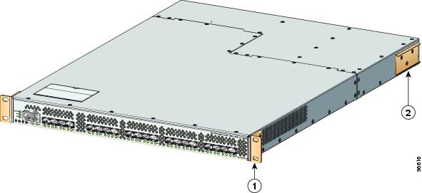
Figure 2-1 Front Rack-Mount Brackets and C Brackets Installed on the Cisco MDS 9100 Series
Step 3
Note
Step 4
a.
b.
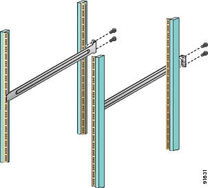
Figure 2-2 Installing the Slider Rails
Figure 2-3 Installing the Notched Slider Rails
Step 5
a.
b.
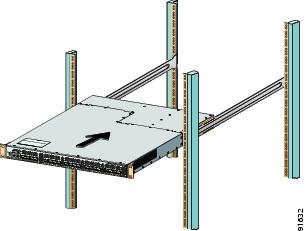
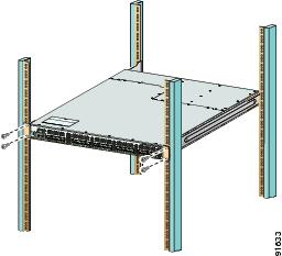
Figure 2-4 Sliding the Cisco MDS 9100 Series onto the Slider Rails
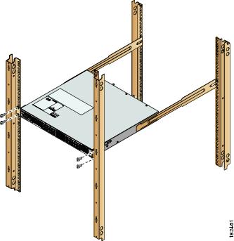
Figure 2-5 Sliding the Cisco MDS 9134 Switch or the Cisco MDS 9124 Switch onto the Notched Slider Rails
Step 6
a.
b.
If you are installing the optional cable guides, place the cable guides in front of the front rack-mount brackets, and then pass the screws through the cable guides, front rack-mount brackets, and mounting rail. You can install one or both cable guides; if installing a single cable guide, it can be installed on either side.
Figure 2-6 Attaching the Switch to the Rack
Figure 2-7 Attaching the Cisco MDS 9134 Switch or the Cisco MDS 9124 Switch to the Rack (Notched Rails)
Installing the Switch in a Cabinet with Insufficient Front Clearance
This section describes how to use the rack-mount kit provided with the switch to install the Cisco MDS 9100 Series switch into a cabinet with insufficient front-facing clearance. The Cisco MDS 9100 Series switch is installed rear-facing to provide adequate clearance for the fibre-optic cables. This cabinet meets the requirements described in Appendix A, "Cabinet and Rack Requirements," except the cabinet has less than three-inch clearance between the inside of the front door or bezel panel and the front cabinet mounting rails. This rear-facing installation is necessary to ensure that the minimum bend radius for the fiber-optic cables is maintained. In these cabinets, the Cisco MDS 9100 Series switch is mounted backwards, with the fiber optic cables facing toward the rear of the cabinet and the power supplies facing the front of the cabinet.
Caution
The rack-mount kit provided with the switch contains the items listed in Table 2-1.
Installing Front Rack-Mount Brackets for Cabinets with 26 Inches or Greater of Rail Spacings
The front rack-mount brackets for the Cisco MDS 9100 Series switch must be installed onto the switch prior to installing the switch into the cabinet. Follow these steps for cabinets with front-mounting rail to rear-mounting rail spacings greater or equal to 26 inches.
Step 1
a.
b.
Step 2
Note
a.
b.
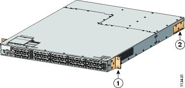
Figure 2-8 Front Rack-Mount Brackets and C Brackets Installed on the Cisco MDS 9100 Series
Installing Front Rack-Mount Brackets for Cabinets with Less Than 26 Inches of Rail Spacings
The front rack-mount brackets for the Cisco MDS 9100 Series switches must be installed onto the switch prior to installing the switch into the cabinet. For cabinets with less than 26-inch rail-to-rail spacing, the front rack-mount bracket must be installed 180 degrees from normal.
To install brackets for cabinets with front-mounting rail to rear-mounting rail spacings less than 26 inches that need to be mounted backwards to maintain adequate fiber-optic clearances, follow these steps:
Step 1
a.
b.
Note
Step 2
Note
a.
b.
Figure 2-9 Front Rack-Mount Brackets (Rotated) and C Brackets Installed on the Cisco MDS 9100 Series
Installing Cisco MDS 9100 Series Switch Rear-Facing into Cabinet
To install a Cisco MDS 9120 or 9140 Switch rear-facing into a cabinet using the rack-mount kit provided with the switch (for cabinets with insufficient front-facing clearance), follow the steps in this section. If you are installing a Cisco MDS 9134 Switch or a Cisco MDS 9124 Switch rear-facing into a cabinet using the rack-mount kit provided, see "Installing a Cisco MDS 9134 Switch or a Cisco MDS 9124 Switch Rear-Facing into Cabinet" section.
Step 1
a.
b.
c.
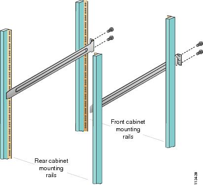
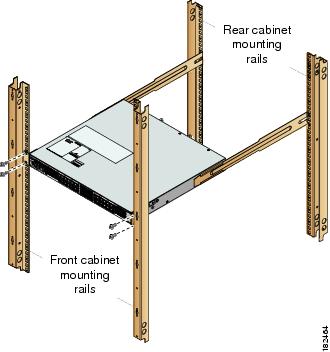
Figure 2-10 Installing the Slider Rails to the Front Rack-Mounting Rails
Step 2
a.
Note
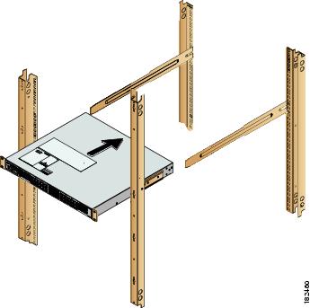
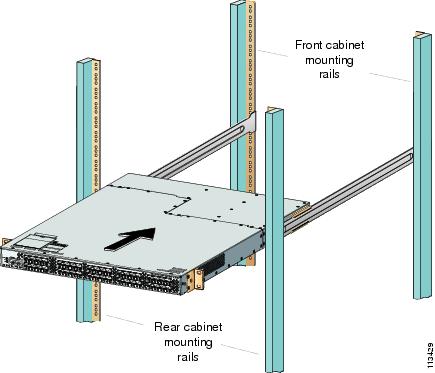
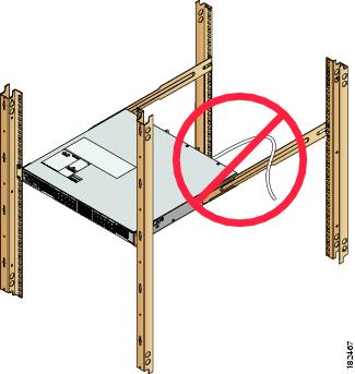
Figure 2-11 Sliding the Cisco MDS 9100 Series Switch (Rear-Facing) onto the Slider Rails
b.
Step 3
a.
Note
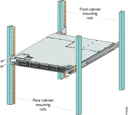
Figure 2-12 Attaching the Cisco MDS 9100 Series Switch (Rear-Facing) to the Cabinet
a.
b.
If you are installing the optional cable guides, place the cable guides in front of the front rack-mount brackets, and then pass the screws through the cable guides, front rack-mount brackets, and rear mounting rail. You can install one or both cable guides; if installing a single cable guide, it can be installed on either side.
Installing a Cisco MDS 9134 Switch or a Cisco MDS 9124 Switch Rear-Facing into Cabinet
To install a Cisco MDS 9134 Switch or a Cisco MDS 9124 Switch rear-facing into a cabinet using the rack-mount kit provided with the switch (for cabinets with insufficient front-facing clearance), follow these steps:
Step 1
Note
a.
b.
c.
d.
Figure 2-13 Installing the Notched Slider Rails to the Front Rack-Mounting Rails
Step 2
a.
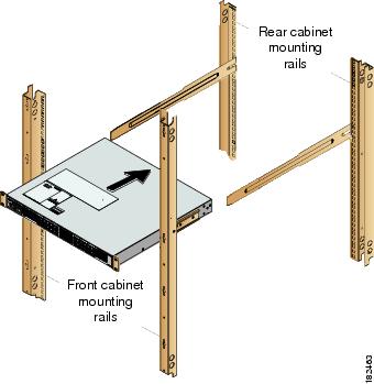
Figure 2-14 Sliding the Cisco MDS 9134 Switch or the Cisco MDS 9124 Switch (Rear-Facing) on the Notched Slider Rails
b.
Step 3
Note
Figure 2-15 Correct Position of Power Cord Routed Through Notched Slider Rail
Figure 2-16 Incorrect Position of Power Cord Routed Over the Notched Slider Rail
Step 4
a.
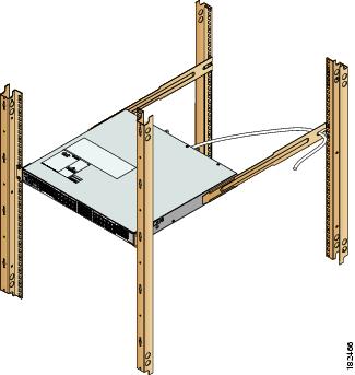
Figure 2-17 Attaching the Cisco MDS 9134 Switch or the Cisco MDS 9124 Switch (Rear-Facing) to the Cabinet
b.
Tip
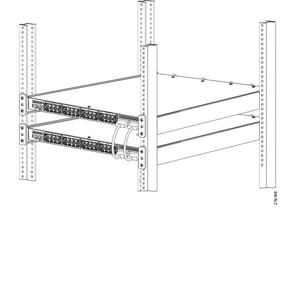
Installing Cisco MDS 9134 48-Port and 64-Port Stackable Bundles
To install two Cisco MDS 9134 Switches to stack and expand up to 48 ports and/or 64 ports, follow these steps:
Step 1
Step 2
Step 3
Step 4
Figure 2-18 Installing the MDS 9134 48-port and 64-port Stackable Bundles
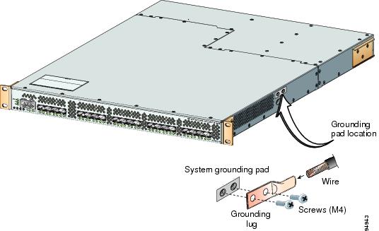
Grounding the Switch
A grounding pad with two threaded M4 holes is provided on the chassis for attaching a grounding lug. Figure 2-19 shows the system ground location on the Cisco MDS 9100 Series.
Figure 2-19 Location of Switch Ground on the Cisco MDS 9100 Series
Warning
Caution
Note
Caution
Note
Note
To attach the grounding lug and cable to the chassis, follow these steps:
Step 1
Step 2
Step 3
Step 4
Step 5
Step 6
Step 7
Starting Up the Switch
This section provides instructions for powering up the switch and verifying component installation.
Caution
Note
To power up the switch and verify hardware operation, follow these steps:
Step 1
Step 2
Note
Step 3
Step 4
Step 5
Step 6
Caution
Step 7
•
•
•
•
Note
If any LEDs other than the Fibre Channel port LEDs are orange or red after the initial boot processes are complete, see the Cisco MDS 9000 Family Troubleshooting Guide.
Step 8
Note
Step 9
Step 10
Note
Removing and Installing Components
The Cisco MDS 9140 Switch and the Cisco MDS 9120 Switch is shipped with two field-replaceable power supplies. Each power supply includes a fixed fan. The Cisco MDS 9140 Switch and the Cisco MDS 9120 Switch also have two field-replaceable fan modules. The Cisco MDS 9134 Switch has two hot-swappable power supplies and two hot-swappable fan modules. The Cisco MDS 9124 Switch is shipped with one field-replaceable power supply and three fixed fans.
This section provides the following information:
•
•
Warning
Caution
Note
With two power supplies installed, if one power supply fails, the system can continue to function normally on a single healthy power supply. However, the failed power supply should be replaced as soon as possible to provide redundancy.
The fan modules are required to ensure proper cooling of the switches. SeeFigure 2-20, Figure 2-21, and Figure 2-22.
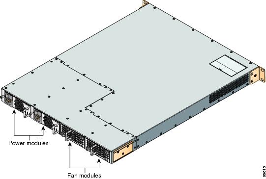
Figure 2-20 Rear View of the Cisco MDS9134 Switch
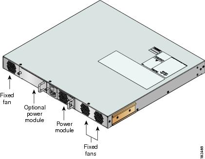
Figure 2-21 Rear View of the Cisco MDS 9124 Switch
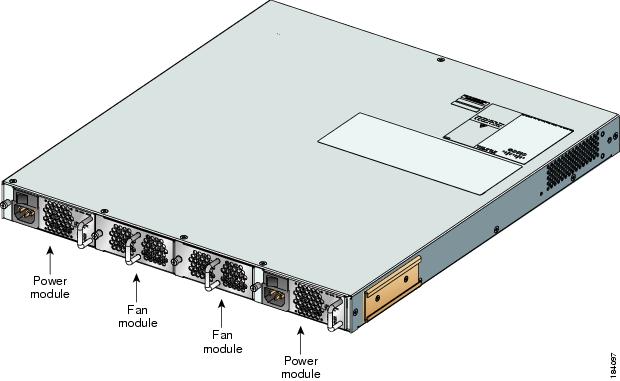
For the Cisco MDS 9140 Switch and the Cisco MDS 9120 Switch, the fans should not be removed for prolonged periods of time during operation. If one fan module fails, a single healthy fan module can temporarily provide sufficient cooling to maintain switch operation under normal conditions, but the failed fan module should be replaced as soon as possible. See Figure 2-22.
Figure 2-22 Rear View of the Cisco MDS 9140 Switch and the Cisco MDS 9120 Switch
Removing and Installing Power Supplies
This section provides instructions for removing and installing the power supplies for the Cisco MDS 9100 Series.
Caution
Removing Power Supplies
To remove a power supply, follow these steps:
Step 1
Step 2
Step 3
Step 4
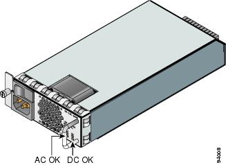
Figure 2-23 Cisco MDS 9100 Series Power Supply
Installing Power Supplies
To install the dual 300-W AC-input power supplies, follow these steps:
Step 1
Step 2
Step 3
Step 4
Step 5
Step 6
Step 7
Note
Step 8
Step 9
If the LED is not green, see the Cisco MDS 9000 Family Troubleshooting Guide.
Removing and Installing Fan Modules
This section provides instructions for removing and installing the fan modules for the Cisco MDS 9140 Switch and the Cisco MDS 9120 Switch. The Cisco MDS 9124 Switch does not have field-replaceable fan modules.
Removing a Fan Module on the Cisco MDS 9140 Switch, the Cisco MDS 9120 Switch, and the Cisco MDS 9134 Switch
The fan module is designed to be removed and replaced while the system is operating without presenting an electrical hazard or damaging the system.
Caution
Warning
To remove the existing fan module, follow these steps:
Step 1
Step 2
Step 3
Step 4
Installing a Fan Module
To install a new fan module, follow these steps:
Step 1
Step 2
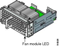
Figure 2-24 Cisco MDS 9100 Series Fan Module
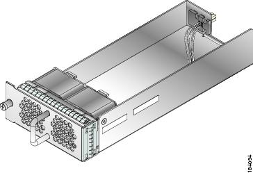
Figure 2-25 shows the Cisco MDS 9134 fan module.
Figure 2-25 Cisco MDS 9134 Fan Module
Verifying the Fan Module
To verify that the new fan module is installed correctly, follow these steps:
Step 1
Step 2
Step 3
Note
Note