Lean Retail Resilient Point-of-Service Application Deployment Guide
Available Languages
Table Of Contents
Lean Retail Resilient Point-of-Service Application Deployment Guide
Payment Card Industry Data Security Standards
Integrated Network Services Layer
Application Networking Services
Store Reference Design Characteristics
Virtualization at the Operating System (OS)
Lean Retail Resilient Point-of-Service Application Deployment Guide
February 4, 2009
Overview
Cisco and Tomax partnered to deliver a Lean Retail Architecture that is agile and resilient. Tomax, a leading retail application suite provider that includes a resilient point-of-sale (PoS), is coupled with Cisco's Lean Retail Architecture to provide a secure foundation that scales to future business requirements while maintaining efficient and flexible operational costs.
Lean Retail is focused on reducing operating and capital expenses by moving applications from the store to the data center. This philosophy increases business agility and reduces cost.
The concept of business agility includes the following:
•
Moving applications from the store to the data center making patches, upgrades, and maintenance faster and less costly
•
•
•
The most important application in any retailer's environment is the PoS application. Historically, retailers did not consider using a thin or lean (centralized data center deployment versus remote branch deployment) retail PoS application due to the perceived risk of WAN failure. Cisco addresses this issue by providing a robust network infrastructure coupled with advanced technologies that are focused on reliability, resilience, and high availability. Lean Retail is a component of the Connected Retail suite of Cisco's business solutions for retailers. Connected Retail provides a set of reference architectures that demonstrate a flexible retail environment that can scale from the needs of today to the business requirements of tomorrow. Connected Retail ranges from simple store deployments that only use data to complex, large enterprise deployments that integrates data, voice, video, security, and other advanced technologies. For more information about the Connected Retail solutions, refer to the following URL: http://www.cisco.com/go/retail
Architectural Goals
An enterprise retail network is a platform constructed to support an extensive range of business functions and applications. The traditional perception of the network relegates its role to one of data transport, providing a reliable fabric for the enterprise. In addition to transport, the ubiquitous nature of the enterprise network fabric allows the introduction of intelligent network services to support business applications. This evolution of the network as an enterprise service platform is natural and supports the Tomax application suite through high availability, security, optimization, scalability, and manageability. The Cisco Lean Retail Data Center Architecture is a holistic approach that allows the network and the applications it supports to work together. This solution increases the performance, availability, scalability, and manageability of enterprise applications in the data center, while simultaneously providing a secure environment. In addition, this solution reduces the complexity and implementation time of enterprise applications in the data center using virtualization technologies and network design best practices.
The specific objectives of the solution are:
•
•
•
•
The remainder of this document focuses on each of these objectives and details the specific deployments of the Tomax PoS application using the services of the Cisco Lean Retail Data Center infrastructure and Connected Retail store designs.
Design Considerations
This solution has some design considerations to achieve the goals of a reliable resilient PoS architecture.
Virtualization
Virtualization is a broad term covering may areas and aspects of various technologies. There are many different ways to virtualize resources and these choices tie directly back into return on investment calculations and architectural road-map designs. Selecting technologies and products that align together are crucial in the development of a scalable architecture. The technology areas of server, network and storage were focused on specifically for the Lean Retail suite of solutions.
Virtualization technologies help businesses treat resources as a set of shared services that can be combined and recombined to improve efficiency and scale quickly. Lean Retail is a migration from traditional static resources such as individual servers, to virtual servers that can be dynamically allocated based on the real time needs of the enterprise. This flexibility allows a retailer to efficiently use the resources available reducing overall cost by getting greater efficiencies from under-utilized resources. This solves the problem of under-scoping initial rollouts of new applications as well as handling peak computing periods.
Storage Virtualization
The SAN can provide a scalable and robust platform for virtualizing storage. In collaboration with partners, Cisco offers network-hosted storage virtualization, which creates an abstraction layer between hosts and storage devices so that IT can achieve much higher levels of storage utilization, on-demand provisioning, and improved data availability and security.
Network Virtualization
Network virtualization is expanding to deploy truly isolated network and service instances that support virtualized hosting environments regardless of the physical platform. By converging multiple virtual networks and hosted network services, Cisco provides network virtualization solutions that allow IT to dynamically create isolated, secure application environments.
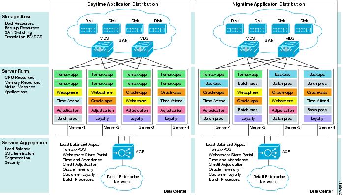
Service Orchestration
Service orchestration is the ability to flexibly use all resources within the domain of the enterprise. A given pool of resources can be dynamically transitioned throughout the business day to meet the current needs with the virtualization of application servers and use of load balancing as shown in Figure 1.
The growth of virtualization in general, and the proliferation of virtual machines in particular, are overcoming many operational challenges such as the following:
•
•
•
Figure 1 Virtualization Brings Business Agility
Payment Card Industry Data Security Standards
Retailers need to be considerate and compliant of the Payment Card Industry (PCI) Data Security Standard. Any segment of the enterprise network that passes or stores Payment Card information is within scope of a retailers PCI audit and needs to be properly secured.
The Lean Retail Resilient Point-of-Service with Tomax solution used security devices (ASAs) implemented in the WAN aggregation layer. These devices were used to terminate encryption tunnels and filter traffic for security and compliance concerns. They must be configured to inspect Cisco Wide Area Application Services (WAAS) traffic due to the optimization and manipulation performed by the WAAS protocol.
At the store level, routers running the firewall feature set need to be configured using zone-based firewall methods, as opposed to classic IOS firewall, due to the lack of inspect capabilities for WAAS traffic. Zone-based firewalls possess the capability to inspect WAAS traffic. The use of zone-based firewalls was not included in this solution validation.

Note
For more information regarding zone-based firewalling, refer to the Zone-Based Policy Firewall Design and Application Guide at the following URL: http://www.cisco.com/en/US/products/sw/secursw/ps1018/products_tech_note09186a00808bc994.shtml
Connected Retail Solution
Connected Retail is Cisco's industry vision that allows retailers to use the strength of the network to connect their brand to today's consumers who are increasingly digital and mobile. Connected Retail's value is demonstrated through the following four portfolios:
•
•
•
•
For more information about the Connected Retail solution portfolios, refer to the following URL: http://www.cisco.com/go/retail|http://www.cisco.com/go/retail
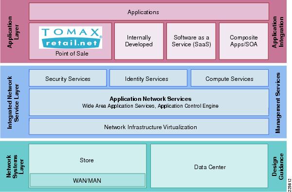
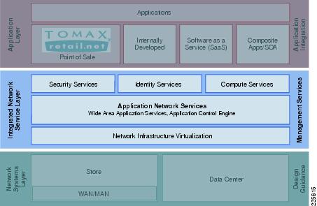
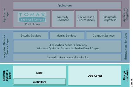
Cisco's Lean Retail Architecture is a solution portfolio comprised of application acceleration, WAN, and data center optimization solutions that allows retailers to "do more with less". The Lean Retail Resilient Point-of-Service with Tomax solution was developed and tested using Cisco's Connected Retail framework. This model depicts the relationships between applications such as the Tomax PoS application and the network infrastructure.
The solution framework is divided into three functional layers:
•
•
•
Figure 2 represents the solution framework.
Figure 2 Connected Retail Framework
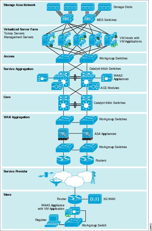
The implementation of the Connected Retail framework results in an architectural design that was used for validation and solution testing. Figure 3 represents the Lean Retail Architecture implemented for the Lean Retail Resilient Point-of-Service with Tomax solution.
Figure 3 Lean Retail Network Architecture
Each of these functional layers of the Connected Retail framework are covered in more detail in the following subsections.
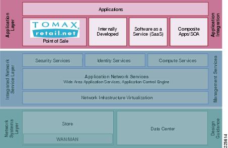
Application Layer
Figure 4 highlights the application layer of the solution architecture. Business and collaboration applications connect users and business processes to the infrastructure. The application layer of the framework includes the business and collaboration applications from Cisco and Tomax.
Figure 4 Application Layer of Connected Retail Framework
Tomax Suite
The Tomax Retail.net product suite is the only comprehensive solution available to retailers that support the features shown in Figure 5.
Figure 5 Tomax Retail.net Product Suite
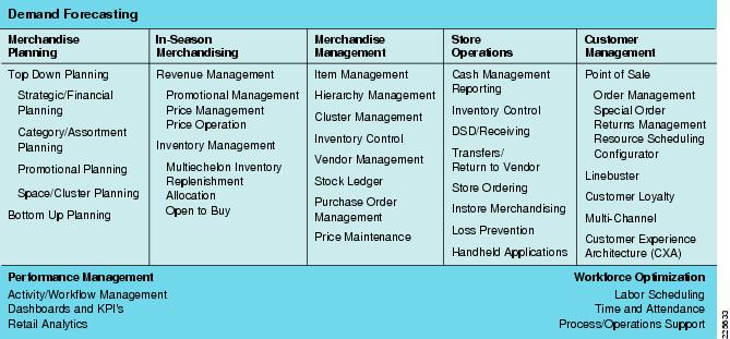
Based on open standards incorporating workflow and open source infrastructure, Retail.net enables rapid deployment and superior time-to-benefit. Customers can gain complete, real-time visibility into operations enterprise-wide with Retail.net modules and achieve on business objectives with phased implementation strategies congruent with their priorities and critical requirements.
Services Oriented Architecture
•
•
•
Customers can get to critical, unique requirements in a more modular fashion—much more quickly and inexpensively.
•
•
•
•
Tomax PoS
The Retail.net Point-of-Sale solution falls under the Retail.net Customer Management groups of solutions that includes the following:
•
•
•
•
•
•
•
•
•
•
Business continuity and managing the customer experience are the most critical aspects of the final point of customer-touch at the register. Retail.net customer management offers retailers with thin client, configurable PoS solutions with unique failover and resilient features. Tomax also provides retailers with powerful tools to optimize the customer experience, including loyalty programs, electronic marketing, linebusting, and workflow-oriented architecture for businesses that prioritize the selling process of retail. Best of all, all activities occurring at the point-of-sale, including transactions, are delivered to the enterprise in real-time, driving critical activities across the demand-driven retail continuum.
Data Synchronization Service
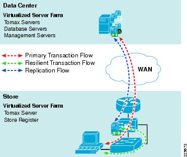
The Tomax PoS application includes data replication capabilities enabling multiple resilient servers and databases to be used by the client terminal. The store resilient servers perform Database-level replication independent of the application context. It is based on light-weight triggering through a highly configurable parallel operation, complete with near-real time intervals and optimized compressed messages. Figure 6 illustrates both the normal primary transaction flow and the resilient transaction flow through data synchronization.
Figure 6 Data Synchronization Service Transaction Flow
Tomax Performance Management
The Retail.net Performance Management solution includes activity/workflow management, dashboards and KPI's, and retail analytics.
Retail.net Performance Management solutions work in combination with Retail.net Workforce Optimization to connect the dots between marketing and merchandising through store operations and workforce management. It is all about giving people access to timely, relevant, and actionable information delivered through portals on PCs and handhelds, connecting people and processes across multiple and disparate data and systems and driving execution through alignment of tasks and activities across the enterprise in concert with strategic objectives. This also includes breakthrough adhoc reporting tools that allow retailers to "google" their data in real-time without the expense and complexity of traditional data warehouse approaches.
Integrated Network Services Layer
Within the Connected Retail framework, the Integrated Network Services layer (see Figure 7) is where filtering, caching, and protocol optimization interact with applications or application middleware services to optimize the performance from the network to the end user. Process control is simplified by using common infrastructure services such as collaboration, security, and identity. These are key advantages that aid in operational reporting and security policy enforcements. Fewer services that are shared across more intelligent devices increases the operational efficiency of the whole system.
Figure 7 Integrated Network Services Layer
The Integrated Network Services layer consists of the following:
•
•
•
•
•
Note
Compute Services
Figure 8 shows the compute services within the Integrated Network Services layer of this solution.
Figure 8 Compute Services
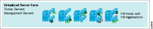
Server virtualization allows flexibility in using resources in serverfarms and is a key component in Cisco's Lean Retail Architecture solutions. The following are three popular approaches to server virtualization currently used across enterprises:
•
•
•
Descriptions of each are available in Glossary. At its core, server virtualization is the method of abstracting and partitioning the underlying hardware to enable multiple guest OS and applications to share a single physical resource while maintaining process isolation. This includes the number of physical servers, processors, and operating systems. It is a software application that divides one physical server into multiple isolated virtual environments. These virtual environments are referred to as partitions, guests, instances, containers, or emulations.
In the Lean Retail Architecture, the virtual machine model is used. Each application server is installed on its own individual guest operating system and each of these servers reside on the SAN as a group of files accessible by any of the physical servers in the data center. The virtualization software used is VMWare's ESX server 3i with VirtualCenter. One key feature of VirtualCenter that enables true autonomic business agility is the capability to schedule when virtual machines startup or shutdown, allowing resources to be fully used through out the day or week, as the needs of the business dictate.
Application Networking Services
Figure 9 shows the Application Networking Services within the Integrated Network Services layer of this solution.
Figure 9 Application Networking Services
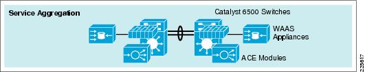
This section provides the main Cisco products and technologies used in the Lean Retail Architecture to enhance Tomax. The following products are addressed:
•
•
Application Control Engine (ACE)
The Cisco ACE Module is used in this Lean Retail environment to provide load balancing for the Tomax application. This technology is used to test the first and second failure scenarios of the resilient objectives (Tomax service engine failure and application server failure, respectively). ACE ensures that Tomax is available by load balancing connections from the stores amongst the available Tomax servers in the data center. It uses advanced health checks for application availability, hardware state, and hardware availability. The Cisco ACE for Cisco Catalyst 6500 Series Switches is a member of the Cisco family of Data Center 3.0 solutions. The Cisco ACE module represents state of the art in next-generation application switches that helps:
•
•
•
•
The Cisco ACE Module achieves these goals through a broad set of intelligent Layer-4 load balancing and Layer-7 content switching technologies integrated with leading acceleration and security capabilities. A key design element of the module is its ability to use virtualized architecture and role-based administration, which enable IT to provision and deliver a broad range of multiple applications from a single module, bringing increased scalability to the data center.
To maximize application availability, the module uses best-in-class application-switching algorithms and highly available system software and hardware. It provides industry-leading scalability and throughput for managing application traffic, up to 16Gbps in a single module and 64Gbps with four modules in a single Catalyst 6500 switch chassis. This is upgradeable through software licenses or new module additions, thus providing IT with long-term investment protection and scalability.
The Cisco ACE Module greatly improves server efficiency through both highly flexible application traffic management and offloading CPU-intensive tasks such as SSL encryption/decryption processing and TCP session management.
Cisco ACE provides a highly available and scalable data center solution for the Tomax application environment. Currently, the ACE is available as an appliance or integrated service module in the Catalyst 6500 platform. The testing of the Tomax application in this solution was restricted to the ACE service module in the Catalyst 6500. ACE features and benefits include the following:
•
•
•
•
•
•
ACE Virtualization
Virtualization is a prevalent trend in the enterprise today. From virtual application containers to virtual machines, the ability to optimize the use of physical resources and provide logical isolation is gaining momentum. The advancement of virtualization technologies includes the enterprise network and the intelligent services it offers.
The Cisco ACE supports device partitioning where a single physical device can provide multiple logical devices. This virtualization functionality allows system administrators to assign a single virtual ACE device to a business unit or applications, such as Tomax, to achieve application performance goals or service-level agreements (SLAs). The flexibility of virtualization allows the system administrator to deploy network-based services according to the individual business requirements of the customer and technical requirements of the application. Service isolation is achieved without purchasing another dedicated appliance that consumes more space and power in the data center.
Configuration of Admin Context allows for resource assignment of other virtual contexts:
resource-class Goldlimit-resource all minimum 0.00 maximum unlimitedlimit-resource conc-connections minimum 10.00 maximum unlimitedlimit-resource sticky minimum 10.00 maximum unlimitedcontext TOMAXdescription TOMAX POSallocate-interface vlan 46allocate-interface vlan 146member GoldConfiguration of the Tomax Context creates a virtualized resource that can be configured and managed independently of other contexts. Within the context all of the load balancing, options and features are configured.
Note
Session Persistence
Session persistence is the ability to forward client requests to the same server for the duration of a session. HTTP session persistence can be achieved through the following:
•
•
Cisco ACE supports each of the above methods, but given the presence of proxy services in the enterprise, Cisco recommends using the cookie sticky method to guarantee load distribution across the serverfarm for web-based traffic. The Tomax application is not web-based, therefore, IP sticky was configured for the load balancing methodology.
In addition, Cisco ACE supports the replication of sticky information between devices and their respective virtual contexts. This provides a highly available solution that maintains the integrity of each session.
Allowed Server Connections and Rate Limiting
Retail data centers typically perform due diligence on all deployed server and network devices, determining the performance capabilities to create a more deterministic, robust, and scalable application environment. The ACE allows the system administrator to establish the maximum number of active connections values on a per-server basis and/or globally to the serverfarm. Additionally, ACE can be configured to rate-limit these connections on a per-VIP and/or real server basis. This features provides feedback to load-balancing decision; it takes real servers exceeding rate limits out of load-balancing and puts them back into load-balancing when the rate is below the limits. This functionality protects the end device, whether it is an application server or network application optimization device such as the WAE.
Health Monitoring
The ACE device is capable of tracking the state of a server and determining its eligibility for processing connections in the server farm. The ACE uses a simple pass/fail verdict but has many recovery and failures configurations, including probe intervals, timeouts, and expected results. Each of these features contributes to an intelligent load-balancing decision by the ACE context.
The following are the predefined probe types currently available on the ACE module:
•
•
•
•
•
•
•
•
•
•
•
•
•
•
•
•
•
Note
Note that the potential probe possibilities available through scripting make the ACE even more flexible and powerful application-aware device. In terms of scalability, the ACE module can support 1000 open probe sockets simultaneously.
Once the context is created, several steps are completed to define a group of servers, create probes to monitor the servers, create a virtual address to receive connections, and control connections and load balancing of the virtual address. The following configurations outline how these capabilities were implemented for solution testing.
Three probes are used to monitor the health and availability of each Tomax server: ping, application TCP port, and server load. The following shows how each of these probes are configured and assigned to the serverfarm:
probe icmp PINGinterval 2probe tcp TOMAXPOSport 8990probe snmp TOMAXsnmpinterval 30community publicoid .1.3.6.1.4.1.2021.10.1.5.1threshold 95rserver host TOMAXAppip address 192.168.46.112inservicerserver host TOMAXDbip address 192.168.46.111inserviceserverfarm host TOMAXprobe PINGprobe TOMAXPOSprobe TOMAXsnmprserver TOMAXAppinservicerserver TOMAXDbinserviceNext, a virtual address for the POS service is assigned (192.168.46.110) that allows load balancing across the servers in the serverfarm. By default, the round-robin method of balancing connection load is used unless another method is specified.
sticky ip-netmask 255.255.255.255 address source src-ip-sticky-tomaxtimeout 10serverfarm TOMAXclass-map match-all VIP-HTTP-11-TOMAX2 match virtual-address 192.168.46.110 anypolicy-map type loadbalance first-match VIP-POLICY-11-TOMAXclass class-defaultsticky-serverfarm src-ip-sticky-tomaxpolicy-map multi-match LB-VIP-TOMAXclass VIP-HTTP-11-TOMAXloadbalance vip inserviceloadbalance policy VIP-POLICY-11-TOMAXloadbalance vip icmp-replyWith an inline bridged mode of implementation, each VLAN interface is assigned to a bridge group and the service policy is applied on the inbound VLAN interface. The BVI interface is used to source the probe monitoring communications.
interface vlan 46bridge-group 1access-group input ANYONEservice-policy input LB-VIP-TOMAXno shutdowninterface vlan 146bridge-group 1access-group input ANYONEno shutdowninterface bvi 1ip address 192.168.46.10 255.255.255.0no shutdownACE supports virtual contexts for load balancing different applications. Each virtual context is essentially an individual load balancer that is capable of making distinct load-balancing decisions that are appropriate for that application. ACE uses a load-balancing predictor to make its load balancing decisions. Two types of predictors were tested in the Tomax Lean Retail Resilient Point-of-Service solution ( round robin and least loaded) and are used for different cases.
Round robin load balancing is when the ACE distributes new connections amongst a server pool in a serial fashion. Every new connection gets sent to the next server, regardless of the processing state of that server. Least loaded load balancing uses more advanced probes that help influence the load balancing decisions. It can get real time performance statistics of the servers in the server farm to weight which servers get the next connection.
The recommended predictor of load balancing for Tomax in a typical, large scale retail environment is round robin for the following reasons:
•
•
•
A more advanced predictor of load balancing is least loaded. It can be useful in less standardized deployments, but it introduces complexity to the load balancing environment for design, support, and operations:
•
•
•
•
Wide Area Application Services (WAAS)
Cisco WAAS has the following two major responsibilities with the Lean Retail Resilient Point-of-Service environment:
•
•
Cisco WAAS provides performance optimizations for store traffic. WAAS is targeted at improving the performance of TCP-based applications across the WAN, while reducing the amount of repetitive data that traverses the WAN. A Wide Area Application Engine (WAE) running WAAS is required on both sides of a WAN link to perform optimization.
To appreciate how WAAS provides WAN and application optimization benefits to the enterprise, consider the basic types of centralized application messages that are transmitted between stores. For simplicity, the following two basic types are identified:
•
•
WAAS uses the technologies described in the following subsections to provide features that include application acceleration, file caching, print service, and DHCP to benefit both types of applications. For more information, refer to the following URL:
http://www.cisco.com/en/US/partner/prod/collateral/contnetw/ps5680/ps6474/product_data_sheet0900aecd80329e39.html|http://www.cisco.com/en/US/partner/prod/collateral/contnetw/ps5680/ps6474/product_data_sheet0900aecd80329e39.html
Advanced Compression Using DRE and Lempel-Ziv Compression
Data Redundancy Elimination (DRE) is an advanced form of network compression that allows Cisco WAAS to maintain an application-independent history of previously-seen data from TCP byte streams. Lempel-Ziv (LZ) compression uses a standard compression algorithm for lossless storage. The combination of using DRE and LZ reduces the number of redundant packets that traverse the WAN, thereby conserving WAN bandwidth, improving application transaction performance, and significantly reducing the time for repeated bulk transfers of the same application.
Transport File Optimizations
Cisco WAAS TCP Flow Optimizations (TFO) uses a robust TCP proxy to safely optimize TCP at the WAE device by applying TCP-compliant optimizations to shield the clients and servers from poor TCP behavior because of WAN conditions. Cisco WAAS TFO improves throughput and reliability for clients and servers in WAN environments through increases in the TCP window sizing and scaling enhancements as well as implementing congestion management and recovery techniques to ensure that the maximum throughput is restored if there is packet loss.
Common Internet File System Caching Services
Common Internet File System (CIFS), used by Microsoft applications, is inherently a highly chatty transactional application protocol where it is not uncommon to find several hundred transaction messages traversing the WAN just to open a remote file. WAAS provides a CIFS Application Optimizer (AO) that inspects and is able to predict what follow-up CIFS messages are expected. The CIFS AO employs read-ahead, asynchronous write, and local caching, significantly reducing the number of CIFS messages traversing the WAN, as well as offloading the remote CIFS server.
Note
Security Features to Meet Compliance Requirements
Several configurations were enabled to support the PCI data security standard:
•
•
•
•
•
•
Deployment Considerations
Specific WAAS implementation methods are covered in the Network Systems Layer, for the store.
This document addresses the integration of network services with the Tomax application. Server load-balancing and security are fundamental services that may be leveraged by data center applications. In addition, this document details the integration of network-based application optimization services in the data center and store. However, these are not the only integrated network services available for the enterprise. The following network services are also accessible as service modules or appliances:
•
•
•
•
•
The Integrated Network Services layer provides services that are distributed across the infrastructure or Network Systems layer.
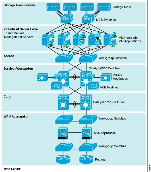
Network Systems Layer
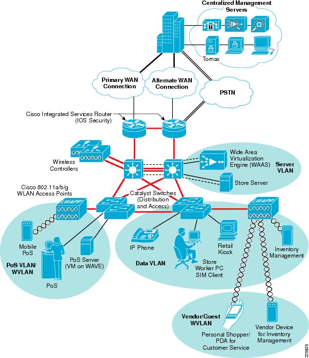
The Network Systems layer (see Figure 10) is where the infrastructure resides. Places in the Network (PIN) reference architectures were used as a contextual backdrop to test the interoperability of the features and functionality of integration between Tomax's application and the Cisco Lean Retail solution. These PIN architectures (data center and branch represented as store) serve as the foundation of the Network Systems layer. They exhibit best practices for retail networks and provide the robust foundation for higher-level services and applications. Each of these architectures contain additional products and features beyond what is necessary for the Lean Retail Resilient Point-of-Sale solution (e.g., wireless products, kiosks, and application acceleration), but are depicted because they are common in most enterprise networks.
Figure 10 Network Systems Layer
For more information about Connected Retail, refer to the following URL: http://www.cisco.com/web/strategy/retail/irn.html
Data Center
The data center is the core of network infrastructure and services. It is the hub that aggregates stores. Data center virtualization is the basis for the transformation of the data center into a service-oriented infrastructure and a key enabler for automation and lights-out operations. By virtualizing data center infrastructure and decoupling applications and data from the physical resources they run on, IT can deliver and maintain data center services more efficiently, resiliently, and dynamically. The network plays a central role in enabling data center virtualization across server, storage and network domains.
Cisco Data Center virtualization provides a foundation for enterprise organizations to achieve the following:
•
•
•
The data center network design is based on a proven layered approach, which has been tested and improved over the past several years in some of the largest data center implementations in the world. The layered approach is the basic foundation of the data center design that seeks to improve scalability, performance, flexibility, resiliency, and maintenance. Figure 11 shows the basic layered design.
Figure 11 Data Center Architecture
The layers of the data center design are the core, aggregation, and access layers. These layers are briefly described as follows:
•
•
•
•
Note
Storage Networking
Figure 12 Storage Area Network
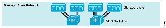
Data center infrastructures must evolve rapidly to improve resiliency, increase business responsiveness, and keep up with the growing demands of new applications while reducing overall power consumption. Storage costs are growing faster than server costs, increasing the need for efficient and cost-effective storage. In highly competitive environments that comply with government regulations for data recovery, 24-hour access to critical information is imperative. By consolidating storage resources into a sharable, manageable, storage network design; better utilization of all available resources can be achieved allowing growth, performance and agility beyond what is available or usable in any single server chassis.
Storage networking provides the following features:
•
•
•
•
Storage networking is central to the Cisco Data Center architecture, providing a networking platform that helps retailers achieve lower total cost of ownership, enhanced resiliency, and greater agility.
Multilayer Director Switches
The Cisco MDS 9000 family provides the leading, high-density, high-bandwidth storage networking hardware, along with integrated fabric applications to support dynamic data center requirements. With the addition of the third-generation modules, the Cisco MDS 9000 family of storage networking products now supports 1-, 2-, 4-, 8-, and 10Gbps Fibre Channel along with Fibre Channel over Ethernet (FCoE). One major benefit of the Cisco MDS 9000 family architecture is investment protection: the capability of first-, second-. and third-generation modules to all coexist in both existing customer chassis and new switch configurations.
With the proliferation of data in today's business environment, organizations are consolidating data center operations into fewer, larger, more manageable SANs. Scalability is crucial because companies must effectively manage and consolidate data center resources while continuously responding to changing business requirements. With the Cisco MDS 9000 family architecture, customers do not need to upgrade their entire current network to support demanding business needs. The Cisco MDS 9000 family provides industry-leading investment protection by delivering full compatibility with existing and new Cisco MDS 9000 family modular switching products.
Note
For an overview of SAN design, refer to the following URL: http://www.cisco.com/en/US/prod/collateral/modules/ps5991/prod_white_paper0900aecd8044c807_ps5990_Products_White_Paper.html
This Lean Retail solution uses a pair of Cisco MDS 9506 directors each with 48-port 4Gbps Fibre Channel blades connecting to a 16TB SAN with redundant 4Gbps controllers. The MDSs are paired and configured with a new VSAN (vsan-2) segmenting these resources from others in the storage network. Virtual SANs are ideal for efficient, secure SAN consolidation, VSANs allow more efficient SAN utilization by creating hardware-based isolated environments within a single SAN fabric or switch. Each VSAN can be zoned as a typical SAN and maintains its own fabric services for added scalability and resilience. VSANs allow the cost of SAN infrastructure to be shared among more users, while ensuring absolute segregation of traffic and retaining independent control of configuration on a VSAN-by-VSAN basis.
Switch interfaces are assigned to the desired VSAN within the configuration:
vsan databasevsan 2 name "RetailESX" loadbalancing src-dst-idfcdomain fcid databasevsan 2 wwn 20:4c:00:0d:ec:2d:94:c0 fcid 0x570100 area dynamicvsan 2 wwn 10:00:00:00:c9:77:dc:c3 fcid 0x570001 dynamicvsan databasevsan 2 interface fc2/1vsan 2 interface fc2/2vsan 2 interface fc2/3vsan 2 interface fc2/4zone default-zone permit vsan 2zoneset distribute full vsan 2Store
The Lean Retail Resilient Point-of-Service solution demonstrates that stores services are resilient based on design. The confidence to centralize applications within the data center is achieved with the knowledge that there are several layers of redundancy built into the solution. Beyond the redundant services that Cisco ACE and storage networking offers within the data center, the stores address several points of failure—WAN and application.
•
•
Several different store architectures (Figure 13) were used in the solution testing; each primarily differed by the implementation of Cisco WAAS: inline and redirection.
Figure 13 Store
Note
WAVE Appliance with Windows on WAAS
The new WAVE appliance's are able to dedicate resources and host virtualized systems know as virtual blades. Resources for each virtual blade are assigned as desired either in the GUI Central Manager or through the CLI. For the Tomax resilient servers in the stores, the following configuration was used:
virtual-blade enablevirtual-blade 1description TOMAX_Server_minimemory 512disk 20boot cd-image disk /local1/vbs/en_win_srv_2003_r2_enterprise_with_sp2_cd2_X13-6 8584.isoboot from diskinterface 1 bridge GigabitEthernet 1/0 mac-address 00:16:3E:F4:89:77device cpu qemu64device nic rtl8139device disk IDEautostartexitOnce the virtual blade was assigned, it was started using the start command: WAVE-MINI-1#virtual-blade 1 start 30, the specification of a 30-second delay allows for the opening of a VNC console to the virtual blade session allowing access to the console for operating system installation and use. Windows 2003 Server Release 2 (2003/R2) was installed from ISO images that were copied to the /local1/vbs/ folder on the WAVE appliance.
Note
To change cd-rom images on the virtual blade, issue the following command: virtual-blade 1 cd disk /local1/vbs/xxx_image_name.iso from the WAVE command line or through the WAAS Central Manager GUI.
It is not necessary for the WAVE appliance to have an IP address on each interface, even if that interface is bridged to the virtual blade. The following configuration shows how the GigabitEthernet interface was configured:
interface GigabitEthernet 1/0description smini-1_fe0-8exit
Note
Note
WAAS Inline and Redirection
Deployment Considerations
There are many form factors of Wide Area Virtualization Engines (WAVE). The WAVEs are the appliances that house both the WAAS and the virtual blade hosting the Windows server. The Windows virtual server on the WAVE houses the redundant Tomax application server that resides in the stores. The WAVE model determines the physical ports and number of virtual blade (servers) available. This is important because of network addressing and segmentation.
Segmentation and addressing are important in this solution because this directly affects the implementation of a retailer's point-of-sale (PoS). Compliance regulations, such as PCI, dictate that you should not mix PoS traffic with management traffic or other non-PoS applications. When selecting smaller appliances (e.g., WAVE-274), there is a single Ethernet interface that does not allow trunking for virtual blade and management connectivity. If other applications are deployed on the blades, they would be in the same network (because there is only one Ethernet interface) and this is not recommended from an PCI perspective. Security and compliance best practices are to minimize the scope of the PoS traffic through distinct segmentation and network addressing.
Inline and redirection are two of the most common interception methods used today and each has ramifications that will influence the deployment.
Inline Interception
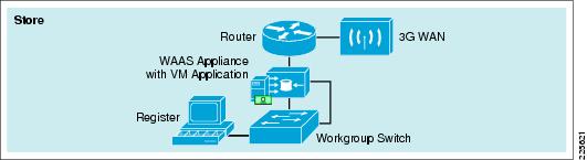
Inline Interception places the WAVE appliance between the store router and the switching infrastructure (see Figure 14).
•
–
–
•
–
–
–
Given that the WAVE device "fails-to-wire", there is little additional concern from an inline appliance failure scenario.
With an inline deployment, the WAVE/WAAS appliance in installed using the inline interfaces between the store switch and the store router. The testing of the Resilient Point-of-Sale solution used the WAVE-274 for a typical mini or small store footprint. For more store characteristics, refer to Appendix.
Figure 14 Store with Inline Deployment

For the mini store the inline interface was used for the management of the WAVE appliance. This allows for the Gigabit Ethernet interface to be solely used for virtual blade traffic and be segmented from all other traffic. The primary interface for management is specified as follows:
primary-interface InlineGroup 1/1!interface InlineGroup 1/1ip address 10.10.95.150 255.255.255.0inline vlan allexitRedirection Interception
Redirection Interception allows the WAVE appliance to be implemented anywhere on the store LAN. Web Cache Communication Protocol (WCCP) is a protocol that specifies interactions between one or more routers and one or more accelerators (WAVEs). The protocol establishes and maintains the transparent redirection of selected types of traffic flowing through a group of routers. The selected traffic is redirected to a group of accelerators with the aim of optimizing resource usage and lowering response times.
•
–
–
–
–
•
–
–
For redundant highly available store architectures that are developed with network resiliency in mind, the most effective way to deploy WAAS on the WAVE appliance is to use WCCP to redirect the WAN traffic.
For testing of the WCCP redirection method of interception, the resilient PoS solution used a WAVE-574 within a large store format (see Figure 15). For more information on store characteristics and architecture, refer to Store Reference Design Characteristics.
Figure 15 Store with Redirection and Redundancy Deployment
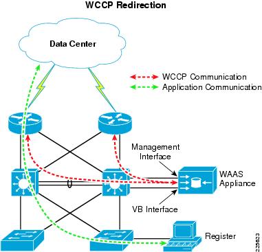
For deployments using WCCP redirection, the router must be configured to accept WCCP queries and specify the appropriate interfaces from which the redirection is to occur. The following configuration shows how one of the routers in Figure 15 permits the WAAS appliance to use WCCP:
! ====WCCP Global Command====ip wccp 61ip wccp 62!! ====WCCP on the WAN interface====interface Serial0/0/0:0.1 point-to-pointdescription RLRG-1 CONNECTION TO RWAN-1ip address 10.10.62.17 255.255.255.252ip wccp 62 redirect inframe-relay interface-dlci 103class fr_qos!! ====WCCP on the VLAN interface====interface GigabitEthernet0/0.12description DATAencapsulation dot1Q 12ip address 10.10.49.2 255.255.255.0ip helper-address 192.168.42.130ip wccp 61 redirect inip pim sparse-dense-modestandby 12 ip 10.10.49.1standby 12 priority 101standby 12 preemptservice-policy input BRANCH-LAN-EDGE-INOn the WAVE appliance, the following configuration directs how WAAS uses WCCP to connect to multiple routers and and redirect appropriate traffic that is to be optimized:
wccp router-list 1 10.10.61.1 10.10.61.2wccp tcp-promiscuous router-list-num 1wccp version 23G Wireless
Whether used for primary access or as a backup link to a traditional wireline connection, 3G WWAN connectivity offers a compelling alternative to the various wireline WAN services. The primary benefits of 3G WWAN include the following:
•
•
•
•
Despite these benefits, the current generation of 3G wireless technologies has limited bandwidth, the main drawback in using 3G for primary access to the WAN. The theoretical downlink speed for the latest commercially available 3G protocols is in the range 3 to 4 Mbps. The uplink speed allows up to 2 Mbps. In practice, 3G links achieve 50 to 60 percent of their theoretical limits. Cisco WAAS accelerates data transfer rates on WAN links that have limited bandwidth, high latency, and high error rates such as 3G and satellite links. By combining Cisco WAAS and the 3G HWIC, the data rate on a 3G link can be increased to 200 to 400 percent of its typical rate.
Cisco 3G WWAN HWIC
The Cisco 3G WWAN HWIC is a high-performance 3G interface card available for Cisco 1841, 1861, 2800 Series, and 3800 Series Integrated Services Routers (ISRs). Suitable for both backup and primary WAN access, the Cisco 3G WWAN HWICs support the latest CDMA and GSM/UMTS standards (EVDO Rev A and HSDPA) and are backward compatible with the widely deployed 2G and 2.5G networks (1xRTT and GPRS and EDGE). The Cisco 3G WWAN HWIC is tightly integrated with the services provided on the award-winning Cisco ISRs, which deliver secure data, voice, video, and mobility services. The Tomax PoS application was not tested over the cellular 3G network.
Main Features and Benefits
•
•
•
•
•
•
•
Note
Configuring 3G WWAN HWIC
Deployment of Cisco Accelerated 3G requires configuration of the Cisco 3G WWAN HWIC. This can be accomplished through the following CLI commands:
! Define the command to be sent by the dialer to DCEchat-script A3GPROVIDER "" "atdt#777" TIMEOUT 30 "CONNECT"!! In line configuration mode Specify default 3G link chat scriptline 0/0/0script dialer A3GPROVIDER!! 3G interface configurationinterface Cellular0/0/0ip address negotiatedencapsulation pppdialer in-banddialer idle-timeout 0dialer string A3GPROVIDERdialer-group 1async mode interactive!! Define access list that permits all trafficaccess-list 1 permit any!! Create dialer list for dialer group 1 that permits access to all trafficdialer-list 1 protocol ip list 1Configuring Cisco 3G WWAN HWIC for Backup with Object Tracking
There are several ways to configure the cellular interface for backup. The following examples show the use of floating static routes with object tracking. Refer to the Cisco 3G WWAN HWIC documentation for additional ways of configuring the Cisco 3G WWAN HWIC for backup.
!Enable tracking on the primary WAN interfacetrack 1 interface FastEthernet0/0 ip routing!!Create a static default route for the primary WAN interface with object trackingip route 0.0.0.0 0.0.0.0 FastEthernet0/0 track 1!!Create a second floating static default route for the backup WAN interface with a metric higher than the primary interface's default routeip route 0.0.0.0 0.0.0.0 Cellular0/0/0 200
Note
For more information about the Cisco 3G GSM/UMTS HWIC, refer to the following URL: http://www.cisco.com/en/US/docs/routers/access/1800/1861/software/feature/guide/3ghwic.html.
Resilient Point-of-Sale
Results and Lessons Learned
Testing was performed in the store and data center locations as discussed in the following subsections.
Store Tests
Before commencement of failure and performance tests, baseline testing was performed to ensure proper functionality from each location including all services within the data center. Several tests were executed to validate the capabilities of the network architecture ensuring business agility and reliability. Table 1 lists the tests performed and their results.
Table 3 in the appendix lists the complete WAAS test result data and the testing descriptions.
WAAS Performance Management Testing Results
•
•
•
•
•
•
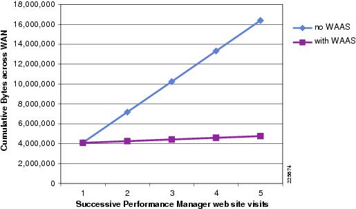
The initial browsing of the Performance Management web-portal generated the same amount of traffic across the WAN for both the WAAS Off and WAAS On tests. Figure 16 shows the WAN load savings when using WAAS as compared to just the browsers built-in caching capability.
Figure 16 Testing Results Comparison
Data Center Tests
The functionality of ACE server load balancing was validated by testing the effectiveness of the server monitoring probes. Each of the configured probes was tested as as specified in Table 2.
Each ACE test completed successfully. Failover times were as expected based on the configured probe monitoring intervals and dead-timer settings. For faster detection of a failed server each of these probes can be configured with more aggressive timings, but care should be taken as probing also creates load which can be counter to the desired goal. The recommended polling interval is between 10 and 15 seconds for thick client applications such as Tomax.
Summary
The Cisco Lean Retail Resilient Point-of-Service with Tomax solution demonstrates several benefits when deploying the Tomax application within the Cisco Lean Retail environment.
Tomax testing was performed from a retail clerk's and retail manager's perspective that included login, transaction, and logout.
Specific solution objectives were as follows:
•
•
•
•
Performance improvement and business agility was found in several areas:
•
•
•
The functional interoperability testing of Tomax's Point-of-Sale application within Cisco's store architectures was successful. This solution's validation enables retailers to confidently progress to a pilot testing stage for technology deployment, and avoids additional costly testing.
Appendix
Product List
Table 3 lists the products installed for the Lean Retail Resilient Point-of-Service with Tomax solution.
Solution Software
Table 4 lists the software installed for the Lean Retail Resilient Point-of-Service with Tomax solution, including the versions tested during validation.
Detailed Testing Information
Store WAAS Tests
The following tests were performed to to show the value of WAAS for Web based applications such as the Tomax Performance Management portal. Table 5 contains the detailed test results data gathered.
WAAS Off
Test 1—Clear browser Cache
Step 1
Step 2
Step 3
Test 2—Load Browser Cache
Step 1
Step 2
Step 3
Step 4
WAAS On
Test 3—Clear Browser Cache and Clear WAAS Cache
Step 1
Step 2
Step 3
Test 4—Load Browser and WAAS Caches
Step 1
Step 2
Step 3
Step 4
Store Reference Design Characteristics
Mini Store
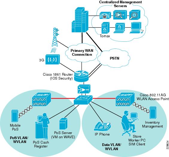
The mini store reference architecture (see Figure 17) is a powerful platform for running an enterprise retail business that requires simplicity and a compact form factor. This combination appeals to many different retail formats that can include the following:
•
•
•
•
•
This network architecture is widely used and consolidates many services into fewer infrastructure components. The small store also supports a variety of retail business application models because an integrated Ethernet switch supports high-speed LAN services.
Figure 17 Mini Store Design
Primary Requirements
Primary requirements are as follows:
•
•
•
•
Advantages
Advantages are as follows:
•
•
•
•
Limitations
Limitations are as follows:
•
•
Large Store
The large retail store reference architecture (see Figure 18) adapts the Cisco campus network architecture recommendations to a large retail store environment. Network traffic can be segmented (logically and physically) to meet business requirements. The distribution layer of the large store architecture improves LAN performance while offering enhanced physical media connections. A larger number of endpoints can be added to the network to meet business requirements. This type of architecture is widely used by large-format retailers globally. Dual routers and distribution layer media flexibility improves network serviceability because the network is highly available and scales to support the large retail store requirements. Routine maintenance and upgrades can be scheduled and performed more frequently, or during normal business hours, through this parallel path design.
Figure 18 Large Store Design
Primary Design Requirements
Primary design requirements are as follows:
•
•
•
•
•
Advantages
•
•
•
•
Limitations
The limitation of this architecture is the higher associated cost because of network resilience based on highly available design.
Glossary
Virtual Machine
Virtual machines are based on the host/guest paradigm. Each guest runs on a virtual imitation of the hardware layer. This approach allows the guest operating system to run without modifications. It also allows the administrator to create guests that use different operating systems. The guest has no knowledge of the host's operating system because it is not aware that it's not running on real hardware. It does, however, require real computing resources from the host - so it uses a hypervisor to coordinate instructions to the CPU. The hypervisor is called a virtual machine monitor (VMM). It validates all the guest-issued CPU instructions and manages any executed code that requires addition privileges. VMware and Microsoft Virtual Server both use the virtual machine model.
Paravirtual Machine
The paravirtual machine (PVM) model is also based on the host/guest paradigm - and it uses a virtual machine monitor too. In the paravirtual machine model, however, The VMM actually modifies the guest operating system's code. This modification is called porting. Porting supports the VMM so it can utilize privileged systems calls sparingly. Like virtual machines, paravirtual machines are capable of running multiple operating systems. Xen and UML both use the paravirtual machine model.
Virtualization at the Operating System (OS)
Virtualization at the OS level works a little differently. It isn't based on the host/guest paradigm. In the OS level model, the host runs a single OS kernel as its core and exports operating system functionality to each of the guests. Guests must use the same operating system as the host, although different distributions of the same system are allowed. This distributed architecture eliminates system calls between layers, which reduces CPU usage overhead. It also requires that each partition remain strictly isolated from its neighbors so that a failure or security breach in one partition isn't able to affect any of the other partitions. In this model, common binaries and libraries on the same physical machine can be shared, allowing an OS level virtual server to host thousands of guests at the same time. Virtuozzo and Solaris Zones both use OS-level virtualization.
Cisco IOS Zone-Based Firewall
Zone-Based Policy Firewall (also known as Zone-Policy Firewall, or ZFW) changes the firewall configuration from the older interface-based model to a more flexible, more easily understood zone-based model. Interfaces are assigned to zones, and inspection policy is applied to traffic moving between the zones. A default deny-all policy prohibits traffic between zones until an explicit policy is applied to allow desirable traffic. Inter-zone policies offer considerable flexibility and granularity, so different inspection policies can be applied to multiple host groups connected to the same router interface. Firewall policies are configured with the Cisco Policy Language (CPL), which uses a hierarchical structure to define inspection for network protocols and the groups of hosts to which the inspection will be applied. ZFW generally improves Cisco IOS performance for most firewall inspection activities. Neither Cisco IOS ZFW or Classic Firewall include stateful inspection support for multicast traffic.
Cisco Validated Design
The Cisco Validated Design Program consists of systems and solutions designed, tested, and documented to facilitate faster, more reliable, and more predictable customer deployments. For more information visit http://www.cisco.com/go/validateddesigns.
ALL DESIGNS, SPECIFICATIONS, STATEMENTS, INFORMATION, AND RECOMMENDATIONS (COLLECTIVELY, "DESIGNS") IN THIS MANUAL ARE PRESENTED "AS IS," WITH ALL FAULTS. CISCO AND ITS SUPPLIERS DISCLAIM ALL WARRANTIES, INCLUDING, WITHOUT LIMITATION, THE WARRANTY OF MERCHANTABILITY, FITNESS FOR A PARTICULAR PURPOSE AND NONINFRINGEMENT OR ARISING FROM A COURSE OF DEALING, USAGE, OR TRADE PRACTICE. IN NO EVENT SHALL CISCO OR ITS SUPPLIERS BE LIABLE FOR ANY INDIRECT, SPECIAL, CONSEQUENTIAL, OR INCIDENTAL DAMAGES, INCLUDING, WITHOUT LIMITATION, LOST PROFITS OR LOSS OR DAMAGE TO DATA ARISING OUT OF THE USE OR INABILITY TO USE THE DESIGNS, EVEN IF CISCO OR ITS SUPPLIERS HAVE BEEN ADVISED OF THE POSSIBILITY OF SUCH DAMAGES.
THE DESIGNS ARE SUBJECT TO CHANGE WITHOUT NOTICE. USERS ARE SOLELY RESPONSIBLE FOR THEIR APPLICATION OF THE DESIGNS. THE DESIGNS DO NOT CONSTITUTE THE TECHNICAL OR OTHER PROFESSIONAL ADVICE OF CISCO, ITS SUPPLIERS OR PARTNERS. USERS SHOULD CONSULT THEIR OWN TECHNICAL ADVISORS BEFORE IMPLEMENTING THE DESIGNS. RESULTS MAY VARY DEPENDING ON FACTORS NOT TESTED BY CISCO.
CCVP, the Cisco logo, and Welcome to the Human Network are trademarks of Cisco Systems, Inc.; Changing the Way We Work, Live, Play, and Learn is a service mark of Cisco Systems, Inc.; and Access Registrar, Aironet, Catalyst, CCDA, CCDP, CCIE, CCIP, CCNA, CCNP, CCSP, Cisco, the Cisco Certified Internetwork Expert logo, Cisco IOS, Cisco Press, Cisco Systems, Cisco Systems Capital, the Cisco Systems logo, Cisco Unity, Enterprise/Solver, EtherChannel, EtherFast, EtherSwitch, Fast Step, Follow Me Browsing, FormShare, GigaDrive, HomeLink, Internet Quotient, IOS, iPhone, IP/TV, iQ Expertise, the iQ logo, iQ Net Readiness Scorecard, iQuick Study, LightStream, Linksys, MeetingPlace, MGX, Networkers, Networking Academy, Network Registrar, PIX, ProConnect, ScriptShare, SMARTnet, StackWise, The Fastest Way to Increase Your Internet Quotient, and TransPath are registered trademarks of Cisco Systems, Inc. and/or its affiliates in the United States and certain other countries.
All other trademarks mentioned in this document or Website are the property of their respective owners. The use of the word partner does not imply a partnership relationship between Cisco and any other company. (0711R)
 Feedback