Planning and Designing the Business Ready Branch Solution
This chapter provides more detailed design information on services deployment, and includes actual router configuration. A more complete set of router configuration commands is provided in Appendix A, "Sample Business Ready Branch Configuration Listings."
This section includes the following topics:
Security
The level of network security that is deployed in an office typically depends on the WAN technology, size, and the security policies enforced by the customer. This section describes how to secure the WAN over a private WAN, MPLS VPN, or the Internet, and how to establish secure entry points into the office network by implementing strong perimeter security. This section includes the following topics:
Securing the WAN
This section includes the following topics:
Securing the WAN Overview
IPSec is used for securing the WAN, and there are two methods of applying IPSec: direct IPSec encapsulation and IPSec-protected generic route encapsulation (GRE). Both methods support the following:
•![]() Static configurations that typically are used for point-to-point VPN connections between IPSec peering routers that have known IP addresses.
Static configurations that typically are used for point-to-point VPN connections between IPSec peering routers that have known IP addresses.
•![]() Multipoint configurations for supporting hub-and-spoke topologies, where the spoke IP addresses may not be known or are dynamically assigned by the service provider.
Multipoint configurations for supporting hub-and-spoke topologies, where the spoke IP addresses may not be known or are dynamically assigned by the service provider.
In both direct IPSec encapsulation and IPSec-protected GRE, there are deployment options for static point-to-point IPSec tunnels and dynamic multipoint IPSec tunnels. As mentioned above, static point-to-point IPSec tunnels are manually configured between each pair of IPSec peering endpoints where endpoint IP addresses are known.
Multipoint dynamic IPSec tunnels use a multipoint configuration, typically on an IPSec VPN head end, which acts as a hub for multiple peering spoke routers in which spoke IP addresses are not known or are dynamically assigned by the DHCP server of the SP. IPSec tunnels are then dynamically created from the spoke (branch) router to the VPN head end when the inter-site traffic requires encryption. This multipoint configuration option saves the network administrator a considerable amount of configuration in the VPN head end but does pose new challenges when troubleshooting.
Although these two IPSec encapsulation methods are somewhat interchangeable, there are some distinct differences that make their use more appropriate to certain applications than others. The next four sections describe how each of these methods work and provide an understanding of which method best fits the application.
Direct IPSec Encapsulation
Direct IPSec encapsulation secures IP unicast traffic passing through an ACL configured on the VPN router. This ACL is used to select specific traffic for encryption, and provides the network administrator granular control over the encrypted traffic sent over the IPSec VPN. Direct IPSec encapsulation cannot carry typical routing protocols because it supports only IP unicast traffic, so the three following alternative methods of establishing endpoint reachability over the VPN are used:
•![]() The underlying routing protocol, if the WAN is under enterprise control
The underlying routing protocol, if the WAN is under enterprise control
•![]() Static routing
Static routing
•![]() Reverse Route Injection (RRI)
Reverse Route Injection (RRI)
Direct IPSec encapsulation is used primarily for VPN connectivity for mobile users, teleworkers, small branch offices with two or less local subnets, or for overlaying IPSec for IP unicast data encryption over an existing private WAN.
Direct IPSec encapsulation has static or dynamic configuration options, using crypto maps for specifying IPSec parameters for encrypting traffic. Static crypto maps are typically used for point-to-point IPSec tunnels where IP addresses of the peering routers are static. Dynamic crypto maps are typically used on a VPN head end or hub where IPSec tunnels are dynamically created by peering spoke routers whose IP addresses are dynamically assigned.
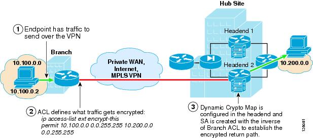
Figure 2-1 shows where static and dynamic crypto maps are typically used.
Figure 2-1 Static and Dynamic Crypto Maps

Static crypto maps are configured in both of the peering routers, and use ACLs for selecting specific traffic for encryption. This enables tunnel creation to be initialized by either end of the IPSec tunnel. Static crypto maps also require that the IP address of the peering router must be known and configured in the static crypto map. Because a static crypto map is configured for every peer, this option is best suited for point-to-point IPSec connections between hub sites or in spoke routers when connecting to a VPN head end or for small meshed IPSec VPNs.
Another option is to use a dynamic crypto map in a headend router. This option is better suited to routers that act as a hub for multiple spoke sites. The dynamic crypto map option streamlines the head end configuration and automates the creation of IPSec tunnels initiated by the spoke routers. Because the IP address of the hub or VPN head end is static, a static crypto map is configured in the branch router, and an ACL is used to specify the traffic to be encrypted. During the IPSec negotiation between the peering routers, an IPSec Security Association (SA) is automatically created in the head end with the inverse of each line of the ACL of the peering router. This defines the encrypted return path back through the head end to the branch router. Because there are no ACLs configured in the head end, this implies that the branch or spoke router must initialize the tunnel.

Note ![]() Although not required, ACLs may be used with dynamic crypto maps to specify which traffic is allowed to initiate a tunnel.
Although not required, ACLs may be used with dynamic crypto maps to specify which traffic is allowed to initiate a tunnel.
Also, because an IPSec SA is created in the head end for each line in the ACL, the number of ACLs in the branch routers should be kept to a minimum. Even so, using dynamic crypto maps is best suited for peering with branch offices with a small number of subnets or a set of subnets that can be summarized to minimize the number of lines in the local ACL and the resulting SAs required in the headend router.
Note ![]() GRE may also be used as a method of minimizing the number of SAs required in the head end, because the ACL has to specify only GRE traffic for encryption. This is discussed further in the following sections.
GRE may also be used as a method of minimizing the number of SAs required in the head end, because the ACL has to specify only GRE traffic for encryption. This is discussed further in the following sections.
One significant difference when using dynamic crypto maps rather than static crypto maps is that the tunnel must always be initiated by the branch router, because the head end has no knowledge of its peering routers until the IPSec tunnel is initiated by the remote.
Dynamic crypto maps require a constant flow of traffic to prevent each SA (that is, an SA for each line of the ACL) from timing out because of inactivity. This "always-on" connection is important in a branch office deployment because quite possibly there can be traffic that originates from the hub site to access information at any one of the subnets in the branch office. This required "always-on" connection can easily be accomplished by any periodic source of traffic such as Simple Network Management Protocol (SNMP) polls from a network management station, IP phone keepalives, or the configuration of Service Assurance Agent (SAA) probes to prevent the SA from timing out.
Note ![]() SAA can be configured to simply send periodic Internet Control Message Protocol (ICMP) probes through the encryption ACLs in the branch router.
SAA can be configured to simply send periodic Internet Control Message Protocol (ICMP) probes through the encryption ACLs in the branch router.
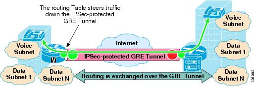
Figure 2-2 shows an example of the use of dynamic crypto maps.
Figure 2-2 Using Dynamic Crypto Maps
IPSec-Protected GRE
IPSec-protected GRE uses a GRE tunnel to encapsulate data traffic before passing through the ACL for encryption. Using GRE allows IP unicast, IP multicast, and other non-IP protocols to be encapsulated and transported over the IPSec VPN. The GRE tunnel is configured in the encryption ACL, and an IP routing protocol is used to steer traffic through the now IPSec-protected GRE tunnel.
Because dynamic routing protocols are typically used for steering traffic for encryption, the appending of the VPN to an existing enterprise-routed domain is fairly straightforward. However, if the VPN is overlaying an existing enterprise private WAN where endpoint reachability is already established, integration can be challenged by overlapping routed domains (VPN and existing WAN) and the need for the redirecting of endpoint traffic through the GRE tunnel for encryption.
Using IPSec-protected GRE provides the following additional benefits:
•![]() Only a single SA is required in the head end for each GRE tunnel.
Only a single SA is required in the head end for each GRE tunnel.
•![]() Branch and headquarters reachability is automatically established using a routing protocol.
Branch and headquarters reachability is automatically established using a routing protocol.
•![]() Failover can be easily accommodated by tuning routing metrics.
Failover can be easily accommodated by tuning routing metrics.
The following sections describe the two configuration options when using IPSec-protected GRE: point-to-point and multipoint configuration.
Static Point-to-Point GRE
Point-to-point (PTP) GRE tunnels are configured between two peering routers where the static IP addresses for the endpoints of the tunnel (tunnel source and tunnel destination) are typically known and are routable over the WAN. Figure 2-3 shows an IPSec-protected PTP GRE tunnel.
Figure 2-3 IPSec Encryption through GRE Tunneling
Dynamic Point-to-Point GRE
A misconception is that PTP GRE cannot be used with dynamically-addressed endpoints because of the static nature of the source and destination configuration of the GRE tunnel interface. This section describes how to use static PTP GRE to support dynamically IP-addressed endpoints by using dynamic PTP GRE.
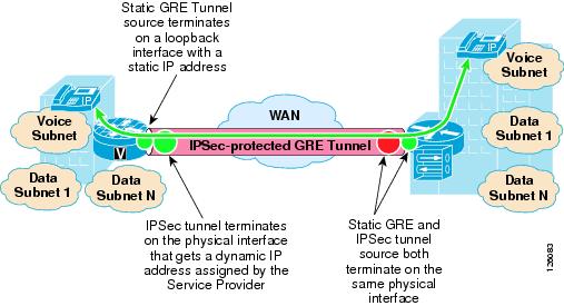
Dynamic PTP GRE is a workaround for the typical static configurations of tunnel source and destination in static PTP GRE. This configuration uses the static address of a loopback interface on the remote endpoint as the GRE tunnel source destination rather than the dynamically-addressed physical interface that would receive an IP address using DHCP. The IPSec source IP address of the remote site is still tied to the physical interface and is dynamically assigned a publicly-routable IP address by the service provider. Traffic from the remote site routing protocol initiates the IPSec tunnel to the hub site.
After this IPSec tunnel is established, the GRE tunnel then comes up and traffic can flow between the remote and the central site. Routing information is exchanged between the remote and central site and reachability is established between the endpoints.
Figure 2-4 shows how dynamic PTP GRE works.
Figure 2-4 Dynamic PTP GRE
Dynamic Multipoint GRE
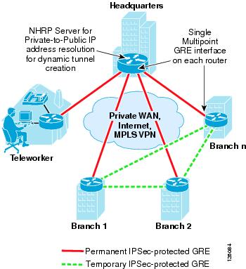
Dynamic multipoint GRE (mGRE), an integral part of the Dynamic Multipoint VPN (DMVPN) architecture, provides a streamlined GRE configuration option where a single GRE interface can support the dynamic creation of GRE tunnels by peering routers. This is similar in concept to using dynamic crypto maps in the direct IPSec encapsulation option previously mentioned. To protect the mGRE tunnels with IPSec, tunnel protection interface commands are used to encrypt the GRE tunnels similar to using the ACL mentioned above. Again, for data traffic to be encrypted, the route table ultimately determines which traffic is sent down the IPSec-protected GRE tunnel.
One other required component when using mGRE is Next Hop Routing Protocol (NHRP). NHRP is used for endpoint IP address resolution for dynamically creating IPSec VPN tunnels between endpoints. This dynamic tunnel capability supports the creation of permanent hub-to-spoke tunnels and optionally on-demand temporary spoke-to-spoke tunnels. This spoke-to-spoke on-demand tunnel creation provides direct IPSec VPN connectivity between branch office routers and does not require the extra encrypt/decrypt cycle required when detouring data traffic through the hub site.
This routing of VPN traffic directly between sites may appear to be the optimal configuration when deploying VPN between branch offices, but careful consideration needs to be made when doing so. For example, the number of tunnels allowed to specific endpoints must be controlled to not exceed device capabilities or available WAN bandwidth. This is similar to using Call Admission Control with IP telephony. However, similar to the dynamic crypto map option, using DMVPN in hub-and-spoke topologies can save considerable VPN head end configuration.
For more detailed information on the known limitations of DMVPN, see the DMVPN FAQ at the following URL: http://www-search.cisco.com/en/US/products/sw/iosswrel/ps1839/products_feature_guide09186a0080110ba1.html.
Note ![]() Spoke-to-spoke dynamic tunnels have not been thoroughly tested and are not recommended at this time.
Spoke-to-spoke dynamic tunnels have not been thoroughly tested and are not recommended at this time.
Figure 2-5 shows a high level view of mGRE in the DMVPN architecture.
Figure 2-5 Using mGRE in the DMVPN Architecture
WAN Security Summary
Customer VPN requirements ultimately drive the method of securing the WAN, whether using direct IPSec encapsulation or IPSec-protected GRE.
The following are considerations when choosing the VPN technology as a WAN for a branch office network:
•![]() Are there other protocols that must be supported besides IP?
Are there other protocols that must be supported besides IP?
GRE can be used to encapsulate other protocols and transport them over IP.
•![]() Is there a requirement to support IP multicast?
Is there a requirement to support IP multicast?
If so, then GRE is required, because IPSec does not support IP multicast natively.
•![]() How many networks are behind the branch office router?
How many networks are behind the branch office router?
If there is a single network or a set of networks that can be summarized into a single routing entry, then direct IPSec encapsulation using dynamic crypto maps may be the preferred solution because of its simplicity. If not, then an IPSec-protected GRE-based VPN may be better, because a routing protocol can be used to advertise the multiple networks behind the branch office router.
•![]() Are there future requirements for spoke-to-spoke dynamic VPN tunnels?
Are there future requirements for spoke-to-spoke dynamic VPN tunnels?
If so, then DMVPN may be an option.
Table 2-1 summarizes the attributes of the different VPN options to provide the network designer help into choosing the best VPN option for the application.
Defending the Perimeter
ACLs, the Cisco IOS Firewall, and the Cisco Intrusion Detection System (IDS) work together to secure the perimeter of the office network. Testing was performed to determine where to deploy these specific features in the office architecture to optimize router performance while providing uncompromised office perimeter security.
Figure 2-6 shows the entry points into the office network where ACLs, Cisco IOS Firewall and/or IDS services could be configured, and the associated traffic flow in and out of these entry points. These entry points may be physical interfaces such as an Ethernet, or logical interfaces such as Frame Relay permanent virtual circuits (PVCs) or Fast Ethernet subinterfaces.
Not all of these entry points and their associated perimeter security may be required in all types of offices. For example, a branch office may not have direct Internet access or a DMZ to secure, so therefore ACLs or a firewall are not required.
Figure 2-6 shows where ACLs and ip inspect commands required for Cisco IOS Firewall are configured on the access router.
Figure 2-6 Office Network Perimeter Security with ACLs and Firewall
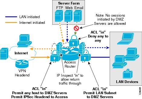
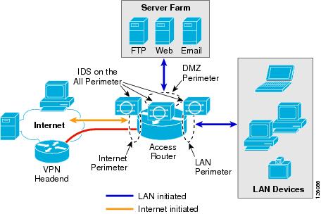
Figure 2-7 shows office network perimeter security with IDS on all perimeters.
Figure 2-7 Office Network Perimeter Security with IDS on all Perimeters
The recommended approach for securing the office network is as follows:
•![]() Use ACLs to tightly restrict traffic inbound to the office network at every entry point.
Use ACLs to tightly restrict traffic inbound to the office network at every entry point.
•![]() Configure firewall inspection (see Figure 2-6) and IDS protection anywhere external sources of traffic are introduced into the office network (see Figure 2-7).
Configure firewall inspection (see Figure 2-6) and IDS protection anywhere external sources of traffic are introduced into the office network (see Figure 2-7).
•![]() The DMZ is considered a traffic sink, and hosts on the DMZ do not initiate any sessions. Only inbound sessions are allowed to initiate sessions back to the source, whether it is a LAN- or Internet-based host.
The DMZ is considered a traffic sink, and hosts on the DMZ do not initiate any sessions. Only inbound sessions are allowed to initiate sessions back to the source, whether it is a LAN- or Internet-based host.
Security policies are configured as follows:
•![]() Packets flow from the perimeter (source) to the perimeter (destination).
Packets flow from the perimeter (source) to the perimeter (destination).
•![]() ACL policies are applied at the perimeter (source) to filter inbound traffic.
ACL policies are applied at the perimeter (source) to filter inbound traffic.
•![]() Firewall inspection and IDS packet monitoring are applied at the source of inbound packet flows.
Firewall inspection and IDS packet monitoring are applied at the source of inbound packet flows.
Table 2-2 summarizes where these three perimeter security features are implemented and how the policies are applied.
Note ![]() Access to the office router (for example, Telnet or SSH) within the office for network management or select ICMP packets may also be permitted, but are not shown for simplicity. These would be additional permit ACLs configured on the Internet perimeter.
Access to the office router (for example, Telnet or SSH) within the office for network management or select ICMP packets may also be permitted, but are not shown for simplicity. These would be additional permit ACLs configured on the Internet perimeter.
|
|
|
|||
|---|---|---|---|---|
|
|
(destination) |
|
|
|
Internet |
DMZ |
Permit any to web, mail, FTP servers |
Internet in |
Internet in |
Internet |
VPN |
Permit IKE, ESP,GRE from VPN head end Permit HQ subnets to LAN subnet1 |
Internet in |
Internet in |
Internet |
LAN |
Deny any |
Internet in |
Internet in |
DMZ |
Internet |
Deny any |
None |
DMZ in |
DMZ |
LAN |
Deny any |
None |
DMZ in |
DMZ |
VPN |
Deny any |
None |
DMZ in |
LAN |
Internet |
Permit LAN subnet to any |
LAN in |
LAN in |
LAN |
DMZ |
Permit LAN subnet to any |
LAN in |
LAN in |
LAN |
VPN2 |
Permit LAN subnet to any |
LAN in |
LAN in |
1 Release 12.3.8T does not require this ACL anymore. 2 If a packet is encapsulated by the router into a GRE tunnel, and the incoming interface is enabled for IDS monitoring, then the packet (before encapsulation) is sent to the IDS Network Module. |
IP Communications
This section includes the following topics:
Quality of Service Overview
This section provides a brief overview of quality of service (QoS) factors that provide high quality voice and video transport across the WAN.
This section includes the following topics:
Delay
Delay is defined as the finite amount of time it takes a packet to reach the receiving endpoint after being transmitted from the sending endpoint. Limiting delay is critical for high-quality voice or video. In the case of voice, this delay is defined as the amount of time it takes for sound to leave the mouth of the speaker and be heard in the ear of the listener.
If the end-to-end voice delay starts to exceed 200 milliseconds (ms), the conversation begins to sound like two parties talking over a satellite link or a CB radio. The International Telecommunication Union (ITU) standard for Voice over IP (VoIP) G.114 states that a one-way, mouth-to-ear delay budget of 150 ms is acceptable for high voice quality. It has been shown that there is a negligible difference in voice quality scores using networks built with 200 ms delay budgets.
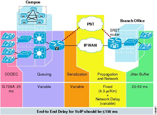
Cisco recommends designing to the ITU standard of 150 ms, but if constraints exist where this delay target cannot be met, then the delay boundary can be extended to 200 ms without significant impact on voice quality. Figure 2-8 shows the various points where delay is incurred when traversing the enterprise network.
Figure 2-8 End-to-End Delay
Delay Variation (Jitter)
Delay variation (jitter) is the difference in the end-to-end delay between packets. Jitter is a factor that must be limited to support high quality voice or video. For example, if one packet requires 100 ms to traverse the network from the source endpoint to the destination endpoint and the following packet requires 125 ms to make the same trip, then the delay variation is calculated as 25 ms. The recommended delay variation or jitter to maintain high-quality voice is less than 30 ms.
Packet Loss
Packet loss is a comparative measure of packets successfully transmitted and received to the total number of packets that were transmitted. Very little packet loss can be tolerated before affecting the quality of voice. Packet loss is expressed as the percentage of packets that were dropped and is typically a function of availability. If the network is highly available, then packet loss during periods of non-congestion is essentially zero. During periods of congestion, however, QoS mechanisms determine which packets are suitable to drop.
Packet loss causes voice clipping and skips. The industry standard codec algorithms used in the Cisco Digital Signal Processor (DSP) can correct for up to 30 ms of lost voice with the use of concealment algorithms. Therefore, the loss of two or more consecutive 20 ms voice samples results in noticeable degradation of voice quality.
Assuming a random distribution of drops within a single voice flow, a drop rate of just 1 percent in a voice stream results in a loss that can not be concealed every three minutes, on average; a 0.25 percent drop rate results in a loss that cannot be concealed once every 53 minutes, on average. The amount of packet loss that can be tolerated is customer-dependent; however, on average, packet loss should be kept to less than 1 percent for high quality voice.
For more detailed information on QoS, see the document at the following URL: http://www.cisco.com/en/US/docs/solutions/Enterprise/WAN_and_MAN/QoS_SRND/QoS-SRND-Book.html.
Table 2-3 summarizes the QoS factors that support high quality voice.
|
|
|
|---|---|
Delay (latency) |
150 ms |
Delay variation (jitter) |
30 ms |
Packet loss |
1% |
Provisioning the WAN
This section describes the basic requirements for provisioning a WAN link to support real-time services such as IP voice and video.
Critical applications such as VoIP require service guarantees regardless of network conditions. The only way to provide service guarantees is to enable queuing at any node that has the potential for congestion, regardless of how rarely this may occur. This principle applies not only to campus-to-WAN/VPN edges, where speed mismatches are most pronounced, but also to campus access-to-distribution or distribution-to-core links, where oversubscription ratios create the potential for congestion. There is simply no other way to guarantee service levels than by enabling queuing wherever a speed mismatch exists.
When provisioning queuing, some best practice rules of thumb also apply. For example, because the best-effort class is the default class for all data traffic, only if an application has been selected for preferential/deferential treatment is it removed from the default class. Because many enterprises have several hundred, if not thousands, of data applications running over their networks, you must provision adequate bandwidth for this class as a whole to handle the sheer volume of applications that default to it. Therefore, it is recommended that you reserve at least 25 percent of link bandwidth for the default best-effort class.
The real-time or strict priority class, which is typically used to transport voice or interactive video (and which corresponds to RFC 3246, "An Expedited Forwarding Per-Hop Behavior"), also requires special bandwidth allocation considerations. The amount of bandwidth assigned to the real-time queuing class is variable. However, if you assign too much traffic for strict priority queuing, then the overall effect is a dampening of QoS functionality for non-real-time applications. Remember that the goal of convergence is to enable voice, video, and data to transparently co-exist on a single network. When real-time applications such as voice or interactive video dominate a link (especially a WAN/VPN link), then data applications fluctuate significantly in their response times, destroying the transparency of the converged network.
Cisco testing has shown a significant decrease in data application response times when real-time traffic exceeds one-third of link bandwidth capacity. Extensive testing and customer deployments have shown that a general best queuing practice is to limit the amount of strict priority queuing to 33 percent of link capacity. This strict priority queuing rule is a conservative and safe design ratio for merging real-time applications with data applications.
Cisco IOS Software allows the abstraction (and thus configuration) of multiple strict priority low latency queuings (LLQs). In such a multiple LLQ context, this design principle applies the sum of all LLQs to be within one-third of link capacity.
Note ![]() This strict priority queuing rule (limit to 33 percent) is simply a best practice design recommendation and is not a mandate. There may be cases where specific business objectives cannot be met while holding to this recommendation. In such cases, enterprises must provision according to their detailed requirements and constraints. However, it is important to recognize the tradeoffs involved with over-provisioning strict priority traffic and its negative performance impact on non-real-time-application response times.
This strict priority queuing rule (limit to 33 percent) is simply a best practice design recommendation and is not a mandate. There may be cases where specific business objectives cannot be met while holding to this recommendation. In such cases, enterprises must provision according to their detailed requirements and constraints. However, it is important to recognize the tradeoffs involved with over-provisioning strict priority traffic and its negative performance impact on non-real-time-application response times.
A very basic WAN edge bandwidth allocation model is shown in Figure 2-9, in which VoIP is restricted to 33 percent of the link, a moderate but guaranteed allocation is made to protect call-signaling traffic, and best-effort traffic is granted at least 25 percent of the link. Additional classes of traffic may be added, as needs evolve, but these should be provisioned within these best-practice guidelines.
Figure 2-9 Provisioning the WAN Link for Voice

Service Provider QoS
In IP-based service provider networks, the implementation of QoS is required to guarantee high quality voice. This is most prevalent where IPSec VPNs are deployed as the enterprise WAN.
Some of the considerations when deploying over an IP-based service provider WAN are as follows:
•![]() The service provider edge QoS configuration must be consistent and complementary to that of the enterprise office router QoS configuration: class-based weighted fair queuing (CBWFQ), LLQ, Traffic Shaping, and Link Fragmentation and Interleaving (LFI).
The service provider edge QoS configuration must be consistent and complementary to that of the enterprise office router QoS configuration: class-based weighted fair queuing (CBWFQ), LLQ, Traffic Shaping, and Link Fragmentation and Interleaving (LFI).
•![]() Packets must be delivered end-to-end with minimal delay, jitter, and loss. This can be accomplished by prioritizing packets based on type of service (ToS) IP Precedence/ Differentiated Services Code Point (DSCP) in the core (QoS-enabled core) or over-provisioning the bandwidth in the core.
Packets must be delivered end-to-end with minimal delay, jitter, and loss. This can be accomplished by prioritizing packets based on type of service (ToS) IP Precedence/ Differentiated Services Code Point (DSCP) in the core (QoS-enabled core) or over-provisioning the bandwidth in the core.
•![]() The enterprise should be aware of service provider policies for handling high priority traffic that exceeds the rate that was agreed upon with the customer and for traffic that crosses the service provider boundary.
The enterprise should be aware of service provider policies for handling high priority traffic that exceeds the rate that was agreed upon with the customer and for traffic that crosses the service provider boundary.
•![]() Negotiating service-level agreements (SLAs) to fulfill end-to-end delay, jitter, and packet loss requirements. Service providers are now offering such SLAs. IP VPN multi-service Cisco Powered Network (CPN) service providers meet the following maximum one-way service levels:
Negotiating service-level agreements (SLAs) to fulfill end-to-end delay, jitter, and packet loss requirements. Service providers are now offering such SLAs. IP VPN multi-service Cisco Powered Network (CPN) service providers meet the following maximum one-way service levels:
–![]() Latency = 60 ms
Latency = 60 ms
–![]() Jitter = 20 ms
Jitter = 20 ms
–![]() Loss = 0.5%
Loss = 0.5%
To find CPN service providers, see the following URL:
http://www.cisco.com/pcgi-bin/cpn/cpn_pub_bassrch.pl
Call Admission Control
Call Admission Control (CAC) maintains high voice quality over an IP WAN by limiting the number of calls that are admitted. This was typically not required with traditional voice networks that use Time Division Multiplexed (TDM) circuits where physical channels limited the number of calls allowed to connect to the PSTN.
This is not the case when VoIP calls traverse an IP WAN where calls are packet streams and there are no physical limitations that control the number of calls admitted to the WAN link. Therefore, an IP WAN link can easily be oversubscribed and the voice quality of all connected calls can be degraded. Because of this problem, some mechanism must be implemented to control the number of admitted calls to maintain high voice quality.
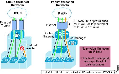
Figure 2-10 compares CAC between traditional TDM-based voice networks and VoIP-based networks.
Figure 2-10 Call Admission Control
IP Telephony
This section includes the following topics:
•![]() Centralized Call Processing with CallManager
Centralized Call Processing with CallManager
•![]() Local Call Processing with CallManager Express
Local Call Processing with CallManager Express
IP Telephony for the Office
There are many aspects to designing an IP telephony network, but this design guide covers only those aspects that are specific to an office deployment. The critical aspects that need to be considered are as follows:
•![]() Provisioning QoS on the WAN link to support voice
Provisioning QoS on the WAN link to support voice
•![]() Configuring CAC
Configuring CAC
•![]() Conferencing and transcoding to support the office
Conferencing and transcoding to support the office
Some of the considerations when deploying IP telephony for the office are as follows:
•![]() The call processing deployment model used: Single Site, Centralized Call Processing, or Distributed Call Processing.
The call processing deployment model used: Single Site, Centralized Call Processing, or Distributed Call Processing.
This design guide focuses on the Centralized Call Processing deployment model using Cisco CallManager. Single Site and Distributed Call Processing deployment models include Cisco CallManager Express. For more information on Single Site and Distributed Call Processing deployment models using Cisco CallManager, see the following URL: http://www.cisco.com/en/US/docs/voice_ip_comm/cucme/srnd/design/guide/models.html.
•![]() The number of off-premise voice calls that are made during the busy hour.
The number of off-premise voice calls that are made during the busy hour.
Basic oversubscription ratios or Erlang ratios can be used to calculate the number of voice lines required both for the local Public Switched Telephone Network (PSTN) calling and toll-bypass calling over the WAN.
•![]() The voice codec used when calling over the WAN.
The voice codec used when calling over the WAN.
Typically, G.729 is used to minimize the amount of bandwidth required, but another consideration is conference calling. The HQ Cisco CallManager may be used for conferencing but only for G.711 calls. Therefore, if G.729 is going to be used for calls over the WAN, then hardware-based digital signal processing (DSP) farms must be used for conferencing and the transcoding between endpoints.
•![]() The number of calls that can be supported over the WAN because of the bandwidth overhead associated with the WAN technology used (for example, Frame Relay, Multi-Link Point-to-Point Protocol (MLPPP), or IPSec VPN).
The number of calls that can be supported over the WAN because of the bandwidth overhead associated with the WAN technology used (for example, Frame Relay, Multi-Link Point-to-Point Protocol (MLPPP), or IPSec VPN).
For example, when sending voice over IPSec VPN, the addition of an IP GRE header and IPSec/Encapsulating Security Payload (ESP) header increases the size of the original voice (or video) IP packet. Using Layer 3 packet sizes, a 60-byte G.729 voice packet increases to 136 bytes with IP GRE and IPSec tunnel mode. A 200-byte G.711 voice packet increases to 280 bytes. This does not include the Layer 2 WAN overhead, which adds an additional 4 bytes for PPP, High-level Data Link Control (HDLC), and Frame Relay, or 14 bytes for Ethernet. See the following URL for more information on VoIP over IPSec VPN: http://www.cisco.com/en/US/docs/solutions/Enterprise/WAN_and_MAN/V3PN_SRND/V3PN_SRND.html.
•![]() Do conference call traffic patterns merit the deployment of local media resources (that is, hardware DSP farm)? In other words, are most conference calls initiated by and held between local branch office IP and PSTN phones?
Do conference call traffic patterns merit the deployment of local media resources (that is, hardware DSP farm)? In other words, are most conference calls initiated by and held between local branch office IP and PSTN phones?
If so, then distributing media resources locally within the branch office conserves WAN bandwidth. In contrast, if the majority of conference call parties are outside the branch office located over the WAN, then locally deploying media resources in the branch probably does not justify the additional costs.
Provisioning for Voice
This section includes the following topics:
•![]() Voice Lines Requirements for Off-Premise Calling
Voice Lines Requirements for Off-Premise Calling
•![]() Bandwidth Requirements for Toll-Bypass
Bandwidth Requirements for Toll-Bypass
Voice Lines Requirements for Off-Premise Calling
There are two types of calls that must be considered when provisioning the branch office for voice: PSTN calls and toll-bypass calls. One of the primary reasons for deploying a branch or an autonomous office in a particular location is to serve that location with whatever product or service the company may offer. This means that some local calls are made to the PSTN, and depending on the business, some calls may traverse the WAN to a connected office. This is commonly referred to as toll-bypass, where the enterprise uses their IP WAN instead of the PSTN to carry the calls to non-local offices to avoid the associated long distance toll charges. Knowing the number of local calls and toll-bypass calls helps to determine the number of voice lines and WAN bandwidth needed for that particular office.
Traditionally, basic oversubscription ratios or Erlang traffic models are used to determine the number of voice lines required for PSTN and toll-bypass calling in a specific size office. Basic oversubscription ratios are typically based on call records collected from other existing offices and applied to the new office. They equate the number of users to the number of PSTN lines required for calling. Typical oversubscription ratios currently used for business offices are four or five users to one voice line. For example, a 20-user office requires four voice lines for PSTN calling if a five to one oversubscription ratio is used.
Using an Erlang traffic model is a more scientific method of determining the number of voice lines required for an office. A few variants of Erlang models can be used, depending on the type of office such as a typical office or a call center. Following is an example of using Extended Erlang B to determine the number of voice lines and WAN bandwidth required for a 23-user office.
An Erlang is a unit of measurement of voice traffic. Strictly speaking, an Erlang represents the continuous use of one voice path or line. In practice, it is used to describe the total traffic volume of one hour.
The Extended Erlang B traffic model is used to estimate the number of lines required for PSTN lines, and takes into account the additional traffic load caused by blocked callers that immediately try to call again if their calls are blocked. The four variables involved are recall factor, busy hour traffic (BHT), blocking, and lines:
•![]() Recall factor is the percentage of calls that immediately retry if their calls are blocked.
Recall factor is the percentage of calls that immediately retry if their calls are blocked.
•![]() Busy hour traffic (in Erlangs) is the number of hours of call traffic during the busiest hour of operation of a telephone system.
Busy hour traffic (in Erlangs) is the number of hours of call traffic during the busiest hour of operation of a telephone system.
•![]() Blocking is the failure of calls because of an insufficient number of lines being available. For example, 0.03 means three calls blocked per 100 calls attempted.
Blocking is the failure of calls because of an insufficient number of lines being available. For example, 0.03 means three calls blocked per 100 calls attempted.
•![]() Lines is the number of lines to the PSTN.
Lines is the number of lines to the PSTN.
Erlang traffic measurements can be used to estimate the number of lines that are required between a voice gateway or IP PBX and a PSTN central office, or between other enterprise offices.
For example, if during the busy hour, each user makes six calls at two minutes per call. This represents .2 Erlangs of BHT per user. The breakdown of this figure is as follows:
•![]() 6 calls @ 2 minutes per call = 12 minutes call traffic per user
6 calls @ 2 minutes per call = 12 minutes call traffic per user
•![]() 12 minutes of traffic per user/60 minutes per hour = .2 Erlang per user of BHT
12 minutes of traffic per user/60 minutes per hour = .2 Erlang per user of BHT
Note ![]() .2 Erlang of BHT per user is used to determine the number of voice lines used for Business Ready Branch testing.
.2 Erlang of BHT per user is used to determine the number of voice lines used for Business Ready Branch testing.
For an office of 23 users, a total of 4.6 Erlangs of BHT must be accommodated with an appropriate number of voice lines. Using an Erlang calculator such as the one found at www.erlang.com, an estimate of voice lines may be calculated for the office (see http://www.erlang.com/calculator/exeb/). For this 23-user office example, nine voice lines are required to accommodate this amount of BHT, assuming only 3 percent of calls would experience blocking.
This information is vital for sizing the routing platform and the amount of WAN bandwidth to be provisioned to support this calculated number of voice calls. Referring to the best practices shown in the last section where 33 percent of the WAN link can be used for real-time traffic, using this voice line calculation can be used to determine the WAN link bandwidth required by this office. The next section discusses this further.
Bandwidth Requirements for Toll-Bypass
The amount of WAN bandwidth to carry all types of traffic may be determined either by the available monetary budget allocated for the WAN circuit or optimally by the services that it will carry. This section describes how to determine the amount of WAN bandwidth that is required by voice and how it is provisioned on the WAN link of the branch office.
The previous section described how to determine the number of voice lines required in the branch based on common oversubscription ratios or Erlang model calculations. Using the 23-user office example where each user creates .2 Erlangs of call traffic during the busy hour, we can assume some number of those calls traverses the WAN to other offices, and therefore some percentage of these lines can be dedicated to toll-bypass calling.
For example, three of the nine lines calculated can be considered for provisioning the WAN link LLQs that are dedicated to real-time traffic. This equates to three Real-Time Protocol (RTP) voice streams that must be accommodated by the WAN connection and configured in CallManager for CAC. In a voice and data only deployment where voice traffic is the only real-time traffic type, 33 percent of the WAN link can be dedicated to voice and the remaining 66 percent for data traffic, as shown in Figure 2-11.
Figure 2-11 Provisioning for Voice
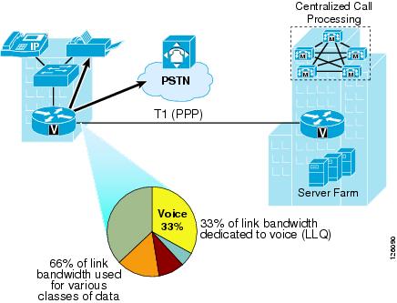
Knowing the amount of bandwidth required for voice helps determine the minimum amount of WAN bandwidth required for both voice and data for the branch office.
After the number of voice lines or, in the case of VoIP, RTP streams are determined for toll-bypass, the minimum amount of WAN bandwidth can be determined. The amount of bandwidth that is required for each RTP stream is dependent on the WAN type and its associated encapsulation method (Frame Relay, IPSec, PPP, and so on) as well as the voice sampling rate. Table 2-4 shows sample bandwidth requirements for RTP streams with varying WAN types.
Table 2-5 shows that a more accurate method for provisioning is to include the Layer 2 headers into the bandwidth calculations.
Assuming G.729A is used over the WAN to conserve bandwidth, 3 RTP streams over a PPP WAN link consume (3 x 26.4 Kbps = 79.2 Kbps) or approximately 80 Kbps of bandwidth for voice. This requires a minimum total WAN link bandwidth of 240 Kbps, assuming 33 percent of the link is used for voice RTP streams. This method uses the services that the link carries as the way to determine the required WAN bandwidth. Of course, if the WAN bandwidth is known, then this calculation determines the number of calls the WAN link can support.
Centralized Call Processing with CallManager
This section includes the following topics:
•![]() Centralized Call Processing with CallManager Overview
Centralized Call Processing with CallManager Overview
•![]() Survivable Remote Site Telephony and Fallback Behavior
Survivable Remote Site Telephony and Fallback Behavior
•![]() Call Admission Control with CallManager
Call Admission Control with CallManager
Centralized Call Processing with CallManager Overview
Centralized Call Processing consists of a single call processing agent that provides services for many sites, and uses the IP WAN to transport IP telephony traffic between the sites. The IP WAN also carries call control signaling between the central site and the remote sites. Figure 2-12 shows a typical Centralized Call Processing deployment, with a Cisco CallManager cluster as the call processing agent at the central site and an IP WAN with QoS enabled to connect all the sites.
Figure 2-12 Centralized Call Processing
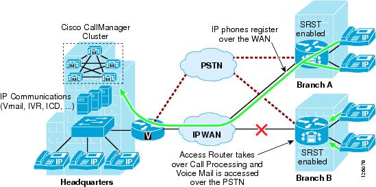
The remote sites rely on the centralized Cisco CallManager cluster to handle their call processing. Applications such as voice mail and Interactive Voice Response (IVR) systems are typically centralized as well to reduce the overall costs of administration and maintenance.
Connectivity options for the IP WAN include the following:
•![]() Leased lines
Leased lines
•![]() Frame Relay
Frame Relay
•![]() Asynchronous Transfer Mode (ATM)
Asynchronous Transfer Mode (ATM)
•![]() ATM and Frame Relay Service Inter-Working (SIW)
ATM and Frame Relay Service Inter-Working (SIW)
•![]() Multiprotocol Label Switching (MPLS) Virtual Private Network (VPN)
Multiprotocol Label Switching (MPLS) Virtual Private Network (VPN)
•![]() Voice and Video Enabled IP Security Protocol (IPSec) VPN (V3PN)
Voice and Video Enabled IP Security Protocol (IPSec) VPN (V3PN)
Routers that reside at the WAN perimeters require QoS mechanisms, such as LLQ and traffic shaping, to protect the voice traffic from the data traffic across the WAN, where bandwidth is typically scarce. In addition, a CAC scheme is needed to avoid oversubscribing the WAN links with voice traffic and deteriorating the quality of established calls.
For Centralized Call Processing deployments, the locations mechanism within Cisco CallManager provides CAC. A variety of Cisco gateways can provide the remote sites with PSTN access. When the IP WAN is down, or if all the available bandwidth on the IP WAN has been consumed, users at the remote sites can dial the PSTN access code or use Automated Alternate Routing (AAR) to have their calls sent through the PSTN. The SRST feature, available on Cisco IOS gateways, provides call processing at the branch offices in the event of a WAN failure.
Follow these guidelines and best practices when implementing the centralized call processing:
•![]() Minimize delay between Cisco CallManager and remote locations to reduce voice cut-through delays (also known as clipping).
Minimize delay between Cisco CallManager and remote locations to reduce voice cut-through delays (also known as clipping).
•![]() For hub-and-spoke topologies, use the locations mechanism in Cisco CallManager for CAC into and out of remote branches.
For hub-and-spoke topologies, use the locations mechanism in Cisco CallManager for CAC into and out of remote branches.
•![]() If the WAN uses Cisco IOS MPLS or IPSec VPN deployment options where bandwidth allocation cannot be associated with a single physical link per connected site, then CAC must be configured to prevent oversubscription of the physical WAN link capacity of the hub link. Again, the CallManager locations feature is used for specifying the HQ call bandwidth capacity.
If the WAN uses Cisco IOS MPLS or IPSec VPN deployment options where bandwidth allocation cannot be associated with a single physical link per connected site, then CAC must be configured to prevent oversubscription of the physical WAN link capacity of the hub link. Again, the CallManager locations feature is used for specifying the HQ call bandwidth capacity.
•![]() If multicast Music on Hold (MoH) is used to branch offices, this bandwidth must be provisioned in the LLQ in addition to normal voice calls. This is because CallManager does not track multicast MoH audio streams.
If multicast Music on Hold (MoH) is used to branch offices, this bandwidth must be provisioned in the LLQ in addition to normal voice calls. This is because CallManager does not track multicast MoH audio streams.
Survivable Remote Site Telephony and Fallback Behavior
The SRST feature provides Cisco CallManager with fallback support for Cisco IP phones attached to a Cisco router on your local network. SRST enables routers to provide call-handling support for Cisco IP phones when they lose connection to remote primary, secondary, or tertiary Cisco CallManager installations; or when the WAN connection is down.
Cisco CallManager Release 3.2 supports Cisco IP phones at remote sites attached to Cisco multiservice routers across the WAN. Before SRST, when the WAN connection between a router and Cisco CallManager failed, or connectivity with Cisco CallManager was lost for some reason, Cisco IP phones on the network became unusable for the duration of the failure. SRST overcomes this problem and ensures that the Cisco IP phones offer continuous (yet minimal) service by providing call handling support for Cisco IP phones directly from the SRST router.
The system automatically detects a failure and uses Simple Subnetwork Auto Provisioning technology to autoconfigure the branch office router to provide call processing for Cisco IP phones registered with the router. When the WAN link or connection to the primary Cisco CallManager is restored, call handling reverts back to the primary Cisco CallManager.
When Cisco IP phones lose contact with primary, secondary, and tertiary Cisco CallManagers, they must establish a connection to a local SRST router to ensure call-processing capability necessary to place and receive calls. The Cisco IP phone retains the IP address of the local SRST router as a default router in the Network Configuration area of the Settings menu. When a secondary Cisco CallManager is not available on the network, the local SRST router IP address is retained as the standby connection for Cisco CallManager during normal operation.
When the WAN link fails, calls in progress are sustained for the duration of the call. Calls in transition and calls that have not yet connected are dropped and must be reinitiated after Cisco IP phones reestablish connection to their local SRST router. Telephone service remains unavailable from the time connection to the remote Cisco CallManager is lost until the Cisco IP phone establishes connection to the SRST router.
Note ![]() CallManager fallback mode telephone service is available only to those Cisco IP phones that are supported by an SRST router. Other Cisco IP phones on the network remain out of service until they are able to reestablish a connection with their primary, secondary, or tertiary Cisco CallManager.
CallManager fallback mode telephone service is available only to those Cisco IP phones that are supported by an SRST router. Other Cisco IP phones on the network remain out of service until they are able to reestablish a connection with their primary, secondary, or tertiary Cisco CallManager.
The time taken to reestablish connection to a remote Cisco CallManager depends in part on the keepalive period set by Cisco CallManager itself. Typically, three times the keepalive period is required for a phone to discover that its connection to Cisco CallManager has failed. The default keepalive period is 30 seconds. If the phone has an active standby connection established with an SRST router, the fallback process takes 10 to 20 seconds after connection with Cisco CallManager is lost. An active standby connection to an SRST router exists only if the phone has the location of a single Cisco CallManager in its CallManager list. Otherwise, the phone activates a standby connection to its secondary Cisco CallManager.
If a Cisco IP phone has multiple Cisco CallManagers in its CallManager list, it progresses through its list of secondary and tertiary Cisco CallManagers before attempting to connect with its local SRST router. Therefore, the time that passes before the Cisco IP phone eventually establishes a connection with the SRST router increases with each attempt to contact a Cisco CallManager. Assuming that each attempt to connect to Cisco CallManager takes approximately one minute, the Cisco IP phone in question can remain offline for three minutes or more following a WAN link failure.
During a WAN connection failure, when SRST is enabled, Cisco IP phones display a message explaining that they are operating in Cisco CallManager fallback mode. The Cisco IP Phone 7960 and Cisco IP Phone 7940 display a "CM Fallback Service Operating" message and the Cisco IP Phone 7910 displays a "CM Fallback Service" message when operating in Cisco CallManager fallback mode. When the Cisco CallManager is restored, the message disappears and full Cisco IP phone functionality is restored.
While in CallManager fallback mode, Cisco IP phones periodically attempt to reestablish a connection with Cisco CallManager at the central office. When a connection is reestablished with Cisco CallManager, Cisco IP phones automatically cancel their registration with the SRST router. A Cisco IP phone cannot reestablish a connection with the primary Cisco CallManager at the central office if it is currently engaged in an active call.
For more details, see the following URLs:
•![]() Survivable Remote Site Telephony Configuration— http://www.cisco.com/en/US/products/sw/iosswrel/ps1839/products_feature_guide_chapter09186a0080110b97.html
Survivable Remote Site Telephony Configuration— http://www.cisco.com/en/US/products/sw/iosswrel/ps1839/products_feature_guide_chapter09186a0080110b97.html
•![]() MGCP Fallback— http://www.cisco.com/en/US/tech/tk1077/technologies_tech_note09186a0080144630.shtml
MGCP Fallback— http://www.cisco.com/en/US/tech/tk1077/technologies_tech_note09186a0080144630.shtml
Call Admission Control with CallManager
Multi-site deployments require some form of CAC to ensure the voice quality of calls transmitted across network links that have limited available bandwidth. Cisco CallManager provides a simple mechanism known as locations for implementing CAC in multi-site WAN deployments with Centralized Call Processing. Follow these guidelines when using locations for CAC:
•![]() Locations require a hub-and-spoke network topology.
Locations require a hub-and-spoke network topology.
•![]() Configure a separate location in Cisco CallManager for each site.
Configure a separate location in Cisco CallManager for each site.
•![]() Configure the appropriate bandwidth limit for each site according to the type of codec used at that site. (See Table 2-6 for bandwidth settings.)
Configure the appropriate bandwidth limit for each site according to the type of codec used at that site. (See Table 2-6 for bandwidth settings.)
•![]() Assign each device configured in Cisco CallManager to a location. If you move a device to another location, change its location configuration as well.
Assign each device configured in Cisco CallManager to a location. If you move a device to another location, change its location configuration as well.
•![]() Cisco CallManager supports up to 500 locations.
Cisco CallManager supports up to 500 locations.
Before Cisco CallManager Release 3.1, a cluster supported only one primary (active) Cisco CallManager server when using locations for CAC. With Cisco CallManager Release 3.1 and later, the locations bandwidth is shared among all Cisco CallManager subscriber servers in the cluster, thus enabling you to use the locations mechanism with any size cluster.
Note ![]() The bandwidth values shown in Table 2-6 and configurable in CallManager may differ from the actual bandwidth required for an RTP stream that would be configured in the LLQ within the router.
The bandwidth values shown in Table 2-6 and configurable in CallManager may differ from the actual bandwidth required for an RTP stream that would be configured in the LLQ within the router.
Automated Alternate Routing
The Automated Alternate Routing (AAR) feature enables Cisco CallManager to establish an alternate path for the voice media when the preferred path between two intra-cluster endpoints runs out of available bandwidth, as determined by the locations mechanism for CAC.
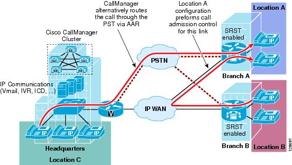
The AAR feature applies primarily to Centralized Call Processing deployments. For example, if a phone in the headquarters calls a phone in branch A and the available bandwidth for the WAN link between the branches is insufficient (as computed by the locations mechanism), AAR can reroute the call through the PSTN. The audio path of the call is IP-based from the calling phone to its local PSTN gateway, TDM-based from that gateway through the PSTN to the branch A gateway, and IP-based from the branch A gateway to the destination IP phone.
AAR can be transparent to the users. You can configure AAR so that users dial only the on-net (for example, 4-digit) directory number of the called phone, and no additional user input is required to reach the destination through the alternate network (such as the PSTN).
Figure 2-13 shows an example of AAR configuration.
Figure 2-13 Automated Alternative Routing
For detailed design and configuration information concerning CAC, see the following URL: http://www.cisco.com/en/US/docs/voice_ip_comm/cucm/admin/3_0_1/p1admiss.html.
Conferencing and Transcoding
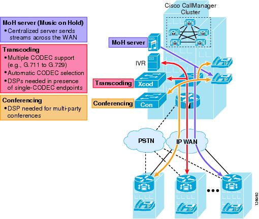
Typically, when call processing is localized at the central site, the MTP, transcoding, and conferencing services may be centralized or distributed, or a combination of both, as shown in Figure 2-14.
Figure 2-14 Centralized Media Resources
If the media resources are centralized, the following results:
•![]() The WAN is used in every call involving one of these resources.
The WAN is used in every call involving one of these resources.
•![]() Frequently, remote sites use low bit-rate codecs across the WAN; thus, conference calls in a Centralized Call Processing model generally require transcoding resources as well. A hardware conferencing resource is the ideal choice in this scenario because it can eliminate the need for dedicated transcoders.
Frequently, remote sites use low bit-rate codecs across the WAN; thus, conference calls in a Centralized Call Processing model generally require transcoding resources as well. A hardware conferencing resource is the ideal choice in this scenario because it can eliminate the need for dedicated transcoders.
•![]() Centrally located resources can cause local calls to traverse the WAN, so you must consider the effects on bandwidth consumption.
Centrally located resources can cause local calls to traverse the WAN, so you must consider the effects on bandwidth consumption.
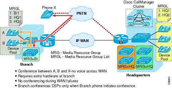
If the media resources are distributed (see Figure 2-15), use the following guidelines:
•![]() Group resources into Media Resource Group Lists (MRGL) based on their location to prevent one remote site from using resources located at another remote site. This practice helps you to manage CAC between the sites.
Group resources into Media Resource Group Lists (MRGL) based on their location to prevent one remote site from using resources located at another remote site. This practice helps you to manage CAC between the sites.
•![]() Use hardware conferencing resources if the cluster contains more than one type of codec (for example, G.711 and G.729).
Use hardware conferencing resources if the cluster contains more than one type of codec (for example, G.711 and G.729).
Figure 2-15 Distributed Conference Resources in the Branch Office
Local Call Processing with CallManager Express
Local Call Processing can be performed by either a local standalone CallManager server in the office or by CallManager Express (CME) integrated in the office router. This section focuses on using the integrated CME for Local Call Processing. CME is primarily used for standalone offices, but can connect to other voice networks such as other CME routers or CallManager using H.323. This section describes some of the considerations that specifically apply to CAC.
This section includes the following topics:
•![]() Call Admission Control with CME
Call Admission Control with CME
Call Admission Control with CME
A limited CAC capability is supported by CME to ensure that the WAN link does not get oversubscribed and therefore degrade voice quality. The max-connection command can be used under the VoIP dial-peer to control the maximum number of call connections that are allowed over that dial-peer (see Figure 2-16).
Figure 2-16 CAC using max-connection Command
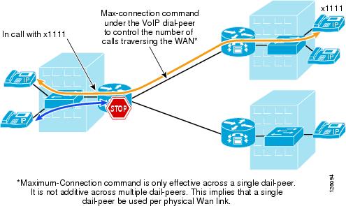
The limitation to this implementation is that the max-connection command is associated only with the dial peer under which it is configured. Therefore, call connections are not counted across multiple dial peers. This method of CAC can be used for very limited hub-and-spoke configurations, where a single dial peer per WAN circuit is used to limit the number of calls that a specific circuit can handle.
A gatekeeper may be used for more complex dial plans. The gatekeeper houses the inter-site dial plan and controls the number of calls allowed to each site. This configuration is used for single WAN-connected sites where there are multiple logical circuits connecting to multiple sites.
See the "Voice Routing" section of the following document for more detailed gatekeeper configuration and design documentation: http://www-search.cisco.com/en/US/products/sw/voicesw/ps4139/index.html
Figure 2-17 shows three sites that are registered with a gatekeeper and how the gatekeeper enforces CAC.
Figure 2-17 Using the Gatekeeper for CAC to Meshed Dial Plans

Sites are registered with the gatekeeper where the inter-site dial plan is configured along with the amount of bandwidth that is available for each site. The gatekeeper provides the phone number-to-IP address mapping of the destination phone and tracks the number of calls made to that particular site. When the maximum number of calls is reached because of the lack of available bandwidth, then the gatekeeper signals this information back to CME and CME presents a busy signal to the calling phone.
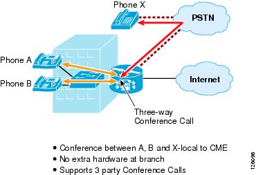
Conferencing and Transcoding
Currently, CallManager Express supports only three-way conference calls and no transcoding, as shown in Figure 2-18.
Figure 2-18 Conferencing with CME
For more information on designing with CME and CUE, see the following URL:
http://www-search.cisco.com/en/US/products/sw/voicesw/ps4625/index.html
 Feedback