Business Ready Branch Solutions for Enterprise and Small Office--Reference Design Guide
Bias-Free Language
The documentation set for this product strives to use bias-free language. For the purposes of this documentation set, bias-free is defined as language that does not imply discrimination based on age, disability, gender, racial identity, ethnic identity, sexual orientation, socioeconomic status, and intersectionality. Exceptions may be present in the documentation due to language that is hardcoded in the user interfaces of the product software, language used based on RFP documentation, or language that is used by a referenced third-party product. Learn more about how Cisco is using Inclusive Language.
- Updated:
- August 29, 2008
Chapter: Business Ready Branch Solution Overview
Business Ready Branch Solution Overview
The Cisco Business Ready Branch or Office solution enables customers to deploy high value network services such as security, IP telephony, business video, and content networking over a variety of WAN technologies. The goal is to make these services fully available to all employees, no matter where they are located.
This chapter provides an overview of the Business Ready Branch Solution, and includes the following sections:
•![]() Understanding the Business Ready Branch Solution
Understanding the Business Ready Branch Solution
•![]() Business Ready Branch Solution Summary
Business Ready Branch Solution Summary
Introduction
This design guide describes how to design a Business Ready Branch or autonomous Business Ready Office where corporate services such as voice, video, and data are converged onto a single office network. This guide is targeted at network professionals and other personnel who assist in the design of branch or commercial office networks.
This guide assists the network designer in successfully designing a branch or an autonomous office. There are numerous combinations of features, platforms, and customer requirements that make up an office design. This design guide focuses on integrated voice, security, and data services within a single access router.
A two-pronged approach was used for testing the access routers: router functionality based on select office profiles (that is, branch offices that contained a specific number of users, PSTN trunks, and a relative amount of WAN bandwidth for that size office); and raw packets-per-second (pps) performance where results were recorded with a graduating number of features being enabled.
The results from this two-pronged approach provide the network designer with the confidence to accurately recommend the specific access router platform that meets customer office network requirements. This document guides the network designer through an example branch office network design, and shows how performance test results are used to select an appropriate office router.
For more information, see the Voice and Video Enabled IPSec VPN (V3PN) Solution Reference Network Design at the following URL: http://www.cisco.com/en/US/docs/solutions/Enterprise/WAN_and_MAN/V3PN_SRND/V3PN_SRND.html.
Various other sources are referenced throughout this document.
Understanding the Business Ready Branch Solution
The Business Ready architecture consists of two deployment models: branch and autonomous office. Although both deployment models are very similar, there are some distinct features and markets that apply to each. Following are some of the attributes that define each deployment model.
The Business Ready Branch has the following attributes:
•![]() An extension of the enterprise campus
An extension of the enterprise campus
•![]() All corporate resources centrally located
All corporate resources centrally located
•![]() Multiple centrally-managed sites
Multiple centrally-managed sites
•![]() Centralized call processing using Cisco CallManager and Cisco Survivable Remote Site Telephony (SRST) for voice
Centralized call processing using Cisco CallManager and Cisco Survivable Remote Site Telephony (SRST) for voice
•![]() WAN access—typically T1 to T3
WAN access—typically T1 to T3
•![]() WAN is primarily a private WAN or Multiprotocol Label Switching (MPLS) virtual private network (VPN) or IP Security (IPSec) VPN over the Internet
WAN is primarily a private WAN or Multiprotocol Label Switching (MPLS) virtual private network (VPN) or IP Security (IPSec) VPN over the Internet
•![]() Up to 240 users
Up to 240 users
The Business Ready Office has the following attributes:
•![]() Mini-campus network
Mini-campus network
•![]() All corporate resources local
All corporate resources local
•![]() Single site, or a loose confederation of autonomous offices
Single site, or a loose confederation of autonomous offices
•![]() Local call processing using Cisco CallManager Express (CCME) and Cisco Unity Express (CUE) for voice mail
Local call processing using Cisco CallManager Express (CCME) and Cisco Unity Express (CUE) for voice mail
•![]() WAN access—typically DSL up to multiple T1s
WAN access—typically DSL up to multiple T1s
•![]() WAN is primarily an IPSec VPN over the Internet
WAN is primarily an IPSec VPN over the Internet
•![]() Remote access VPN is integral for providing mobile worker access to the corporate resources
Remote access VPN is integral for providing mobile worker access to the corporate resources
•![]() Up to 100 users (based on CUE module support of mailboxes)
Up to 100 users (based on CUE module support of mailboxes)
The router currently used in the office as a key component in the Business Ready architecture is no longer simply an access router providing WAN or Internet connectivity, but an integral part of multiple service architectures that are converged onto a single packet-based network. The office network consists of several services integrated into either a single or a small number of networking devices. These devices are typically a modular access router with an integrated Ethernet switch or an access router coupled with an external Ethernet switch.
Wireless access points (APs) may also be used in addition to or in place of the Ethernet switch for end device connectivity. When these offices go beyond the 240 users for the branch or 100 users for the autonomous office, their design resembles that of a campus, so campus design guidelines must be followed. The campus design guidelines are found at the following URL: http://www.cisco.com/en/US/netsol/ns815/networking_solutions_program_home.html.
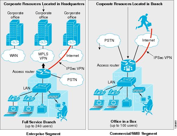
Figure 1-1 shows a high level view of these two office deployment models and their associated market segment.
Figure 1-1 Business Ready Branch Overview
Service Building Blocks
This section includes the following topics:
•![]() Service Building Blocks Overview
Service Building Blocks Overview
Service Building Blocks Overview
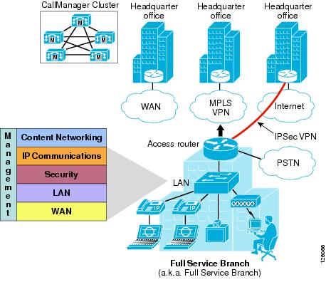
The Business Ready Branch or Office solution uses a layered model in which services are organized into specific categories or building blocks. These building blocks can then be combined to fit specific customer service needs.
The branch and autonomous office have distinct characteristics that influence the combination of building blocks that may be implemented. With the Business Ready Branch, corporate resources such as server farms, IP telephony call processing agents (CallManager), and Internet access are located in a headquarters or regional office and are accessed over the WAN connection. With the autonomous Business Ready Office, all corporate resources and Internet access are located locally within the office. These characteristics as well as the WAN deployment option affect the platform and type of security services that are deployed in the office. The following sections explore each of the service building blocks and describe the choices and guidelines when building the branch.
Figure 1-2 shows an exploded view of the service building blocks that make up the office network.
Figure 1-2 Business Ready Branch Building Blocks
WAN Services
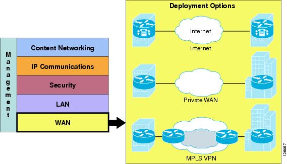
Starting at the bottom of the stack, WAN services provide the foundation for the Business Ready Branch or Office connection to the outside world. The WAN services building block consists of three fundamental deployment options, each with its own set of associated attributes as shown in Figure 1-3.
Figure 1-3 WAN Services
These attributes influence the use of specific features and require special considerations when designing a branch office. For example, if a branch office is connected to the Internet, an IPSec VPN may be required for data privacy between branch and home offices or mobile workers. Another example is Call Admission Control (CAC), which is required for IP telephony or video. These and other examples of services that are influenced by the WAN deployment model are discussed throughout this design guide.
Figure 1-4 lists the WAN deployment options and some of their attributes that influence the design of the branch office.
Figure 1-4 WAN Deployment Options

LAN Services
LAN services provide end device connectivity to the corporate network within the office. With the convergence of services onto a single network infrastructure, devices such as computers, telephones, surveillance cameras, cash registers, kiosks, and inventory scanners all require the connection to the corporate network over the LAN. This assortment of devices requires simplified connectivity tailored to the demands of each device. For example, devices such as IP telephones or cameras may be powered using the LAN switch, automatically assigned an IP address, and be placed in a virtual LAN (VLAN) to securely segment them from the other devices.
Wireless APs may be used to provide secure mobile access for laptop computers, scanning devices, wireless IP phones, or kiosks where wiring is difficult to install. These are just a few examples of the LAN services that are used in the Business Ready Branch or Office solution. Figure 1-5 shows the three different physical configurations that may be used in the LAN services building block.
Figure 1-5 LAN Services
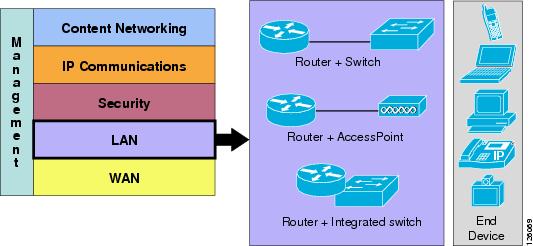
The three configurations that are referenced in this document are as follows:
•![]() Access router connected to a physically separate Cisco Catalyst switch
Access router connected to a physically separate Cisco Catalyst switch
•![]() Access router with an integrated switch
Access router with an integrated switch
•![]() Access router and an AP
Access router and an AP
Table 1-1 highlights some of the advantages and disadvantages of each option.
Some of the other considerations when deploying an office LAN are which devices and services must be supported. The following list describes the other considerations of the LAN service building block:
•![]() Quality of service (QoS)—Required to maintain high-quality voice or video within the local LAN or wireless LAN. This includes the defining of trust on ports to prohibit unauthorized use of QoS for preferential treatment of traffic on the office network.
Quality of service (QoS)—Required to maintain high-quality voice or video within the local LAN or wireless LAN. This includes the defining of trust on ports to prohibit unauthorized use of QoS for preferential treatment of traffic on the office network.
•![]() Virtual LAN (VLAN)—Required to segment the office to provide logical division between services. For example, IP telephony should reside on its own VLAN, separate from that used by the data network.
Virtual LAN (VLAN)—Required to segment the office to provide logical division between services. For example, IP telephony should reside on its own VLAN, separate from that used by the data network.
•![]() 802.1q VLAN tagging—Provides trunking services for IP phones and uplinks to APs or the access router for network routing.
802.1q VLAN tagging—Provides trunking services for IP phones and uplinks to APs or the access router for network routing.
•![]() Inline power—Provides power to the IP phones, APs, or other IP-enabled devices (for example, IP cameras) over the Ethernet cable.
Inline power—Provides power to the IP phones, APs, or other IP-enabled devices (for example, IP cameras) over the Ethernet cable.
•![]() Port security—Limits the number of MAC addresses allowed on an access port.
Port security—Limits the number of MAC addresses allowed on an access port.
For the office network considered in this design guide, the Smartports feature and its canned port templates are used for the LAN switch configuration. Figure 1-6 shows a high level diagram of the devices and port profiles used in the office testing.
Figure 1-6 Office Port Profiles
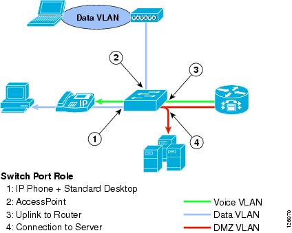
More information on Smartports can be found at the following URL: http://www.cisco.com/en/US/docs/switches/lan/catalyst3750/software/release/12.2_40_se/configuration/guide/swmacro.html.
Security
This section includes the following sections:
Security Overview
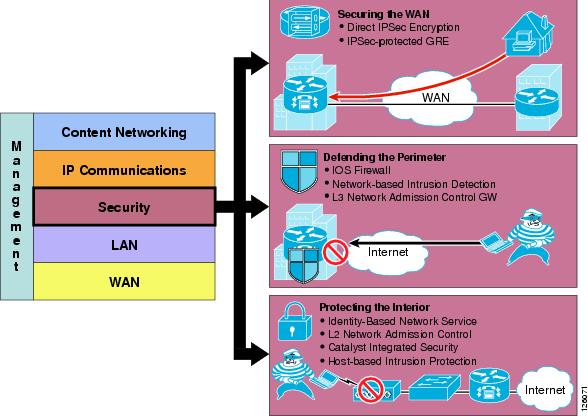
Security is deployed in three places in the office network: on the WAN, on the perimeter between the WAN and the LAN, and on the office LAN.

Note ![]() This document includes only the features integrated in the access router. Therefore, this version of the design guide covers only those integrated features used for securing the WAN and defending the perimeter of the branch office.
This document includes only the features integrated in the access router. Therefore, this version of the design guide covers only those integrated features used for securing the WAN and defending the perimeter of the branch office.
Figure 1-7 shows the breakdown of the security building block and the associated technologies used for securing each of these places in the office network.
Figure 1-7 Security Services
Securing the WAN
Securing the WAN consists of using IP Security (IPSec) to secure data traffic traversing the WAN. The IPSec protocol provides data confidentiality through strong encryption, endpoint authentication, and data integrity, and is used as an overlay to the Internet, an enterprise private WAN, or MPLS VPN.
Some of the considerations when securing the WAN are as follows:
•![]() Type of WAN—Internet, private WAN, or MPLS VPN
Type of WAN—Internet, private WAN, or MPLS VPN
•![]() Type of traffic to be sent over the VPN, such as IP unicast or IP multicast
Type of traffic to be sent over the VPN, such as IP unicast or IP multicast
•![]() Best VPN deployment option, such as Direct IPSec Encapsulation or IPSec-protected generic routing encapsulation (GRE)
Best VPN deployment option, such as Direct IPSec Encapsulation or IPSec-protected generic routing encapsulation (GRE)
•![]() Configuration complexity or size
Configuration complexity or size
•![]() Authentication method—Preshared keys, digital certificates, EZVPN (EZVPN does not support GRE)
Authentication method—Preshared keys, digital certificates, EZVPN (EZVPN does not support GRE)
•![]() Use of high availability, dual head ends, using routing protocols such as Hot Standby Routing Protocol (HSRP)
Use of high availability, dual head ends, using routing protocols such as Hot Standby Routing Protocol (HSRP)
Deploying IPSec VPN over the Internet
Using IPSec VPN has become a common method of securing enterprise traffic over the Internet. Each available IPSec VPN option has advantages and disadvantages, which are mentioned in this section and described in more detail in Chapter 2, "Planning and Designing the Business Ready Branch Solution."
The following are some of the considerations when deploying IPSec VPN as a means of connecting offices:
•![]() Dynamic IP addressing—Although branch offices typically have T1 access link to the Internet with fixed IP addresses, cable or DSL are viable alternative access links, and dynamic IP addressing may need to be accommodated by the VPN technology used.
Dynamic IP addressing—Although branch offices typically have T1 access link to the Internet with fixed IP addresses, cable or DSL are viable alternative access links, and dynamic IP addressing may need to be accommodated by the VPN technology used.
•![]() Level of acceptable quality—If voice or video traverses the WAN, then determining the level of acceptable quality over the Internet must be considered. This may require the negotiation of service level agreements with service providers.
Level of acceptable quality—If voice or video traverses the WAN, then determining the level of acceptable quality over the Internet must be considered. This may require the negotiation of service level agreements with service providers.
•![]() Higher level of security—Support of a higher level of security may be required for the office network because of the direct connection to the public Internet. Split tunneling of traffic for local Internet used at the branch office requires a firewall for protection.
Higher level of security—Support of a higher level of security may be required for the office network because of the direct connection to the public Internet. Split tunneling of traffic for local Internet used at the branch office requires a firewall for protection.
•![]() Type of authentication—May include EZVPN, digital certificates, or static pre-shared keys. The use of digital certificates is recommended because of its high level of security and ease of key management when deploying several branch offices.
Type of authentication—May include EZVPN, digital certificates, or static pre-shared keys. The use of digital certificates is recommended because of its high level of security and ease of key management when deploying several branch offices.
Deploying IPSec VPN over a Private WAN or MPLS VPN
Enterprises are now considering using IPSec VPN technology to provide data privacy over their private WANs because of new privacy laws. This is a viable solution but has the additional challenge of integrating into the enterprise network.
There are two fundamental components that need to be considered when using IPSec VPN for providing data privacy over a private WAN or MPLS VPN: using IPSec for securing the data, and the routing control plane required for establishing endpoint reachability over the VPN. In the traditional IPSec VPN deployment, the enterprise controls the endpoints that send the data to be protected and therefore controls the routing or reachability between the endpoints.
The service provider (SP) has no knowledge of the IP-addressed endpoints of the enterprise. The SP controls the routing between the enterprise VPN routers where the SP owns and controls the reachability of the IP addresses that are assigned to the SP-connected interface of the VPN router. Figure 1-8 shows this relationship.
Figure 1-8 IPSec VPN Overview
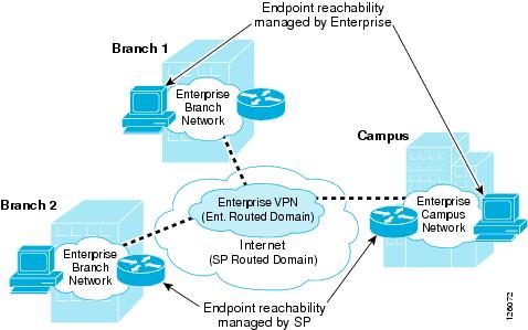
This relationship of the two autonomous routed domains (enterprise and SP) is a fundamental characteristic of a typical IPSec VPN deployment. Because the enterprise does not have control over the WAN routing, routing methods such as static, Reverse Route Injection (RRI), and dynamic are used to establish reachability between the endpoints connected over the VPN.
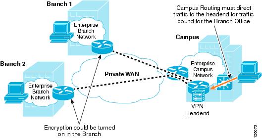
When deploying VPN as a means of data privacy between branch offices in an existing enterprise private WAN or MPLS VPN, one consideration is how to incorporate this autonomous routing domain. In either of these WAN deployments, the enterprise network already understands how to route between endpoints, so inserting a VPN into the existing network now requires the redirecting of traffic through the local VPN router for encryption. This can be fairly straightforward for the branch office because IPSec can be turned on in the WAN-connected access router.
However, on the campus side of the network, this same approach is probably not permitted because this means turning on IPSec in a WAN-aggregation router. In this case, the installation of a separate VPN headend in the campus is required, and network routing must be modified to steer traffic destined to the branch offices through the VPN headend.
Figure 1-9 shows this private WAN or MPLS scenario.
Figure 1-9 Inserting VPN into an Existing Private WAN or MPLS VPN
This complexity of deploying IPSec VPN over an existing private WAN or MPLS VPN is one of the primary challenges of securing the WAN, and you must plan comprehensively to ensure a seamless implementation.
Chapter 2, "Planning and Designing the Business Ready Branch Solution," provides more detailed information to aid the network designer in choosing the best option for securing the WAN.
Defending the Perimeter
This section provides a high level overview of the Cisco IOS Firewall, access control lists (ACLs), and Cisco Intrusion Detection System (IDS) security features implemented at the perimeters of the office network. This section introduces an overview of these features, with implementation recommendations to follow in Chapter 2, "Planning and Designing the Business Ready Branch Solution."
Figure 1-10 shows an example of the perimeter of an office network.
Figure 1-10 Office Network Perimeter Defined
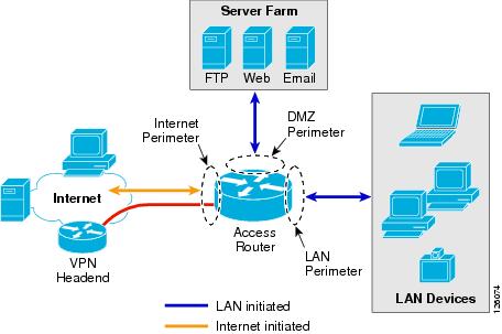
Cisco IOS Firewall and ACLs
The Cisco IOS Firewall provides integrated, inline security services and provides lock-tight, stateful security and control for each protocol traversing the office router. Figure 1-11 shows how traffic flows through the office router between the different office perimeters.
Figure 1-11 Traffic Flows through the Office Network Perimeters
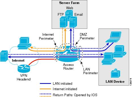
ACLs provide strict control of traffic entering the office network (represented by the solid arrows) and the Cisco IOS Firewall opens and inspects the return path for traffic (represented by the dotted arrows) initiated from within the office network.
Note ![]() For more information on configuring Cisco IOS Firewall, see the following URL: http://www.cisco.com/en/US/products/sw/secursw/ps1018/index.html.
For more information on configuring Cisco IOS Firewall, see the following URL: http://www.cisco.com/en/US/products/sw/secursw/ps1018/index.html.
Chapter 2, "Planning and Designing the Business Ready Branch Solution," describes in more detail how the ACLs and IP inspect commands of the Cisco IOS Firewall are configured to defend the perimeters of the office network.
Intrusion Detection System
The Cisco IOS Intrusion Prevention System (IPS) acts as an inline intrusion detection sensor, watching packets and sessions as they flow through the router and scanning each packet to match any of the Cisco IOS IPS signatures. When it detects suspicious activity, it responds before network security can be compromised and logs the event through Cisco IOS syslog or the Cisco Secure Intrusion Detection System Post Office Protocol. The network administrator can configure the Cisco IOS IPS to choose the appropriate response to various threats. When packets in a session match a signature, the Cisco IOS IPS takes any of the following actions, as appropriate:
•![]() Sends an alarm to a syslog server or a centralized management interface
Sends an alarm to a syslog server or a centralized management interface
•![]() Drops the packet
Drops the packet
•![]() Resets the connection
Resets the connection
Cisco developed its Cisco IOS software-based intrusion prevention capabilities and Cisco IOS Firewall to be flexible, so that individual signatures can be disabled in case of false positives. Generally, it is preferable to enable both the firewall and Cisco IOS IPS to support network security policies. Each of these features may be enabled independently and on different router interfaces. Chapter 2, "Planning and Designing the Business Ready Branch Solution," provides recommendations on how each of these features is implemented to secure the office network perimeter.
The following are considerations when applying ACLs, configuring Cisco IOS Firewall, and Cisco IDS:
•![]() With Release 12.3.7T and earlier, Cisco IOS Firewall and IDS use a common session-state inspection machine, so router performance impact is nearly the same when using the Cisco IOS Firewall alone or Cisco IOS Firewall and IDS together. This is true for both software-based IDS and hardware-based IDS (NM-CIDS). In fact, a slight decrease in performance is observed when using hardware-based IDS, because of the additional processing required for copying the packet to the IDS module. Even so, the benefit of using hardware-based IDS is the increased number of attack signatures that are monitored.
With Release 12.3.7T and earlier, Cisco IOS Firewall and IDS use a common session-state inspection machine, so router performance impact is nearly the same when using the Cisco IOS Firewall alone or Cisco IOS Firewall and IDS together. This is true for both software-based IDS and hardware-based IDS (NM-CIDS). In fact, a slight decrease in performance is observed when using hardware-based IDS, because of the additional processing required for copying the packet to the IDS module. Even so, the benefit of using hardware-based IDS is the increased number of attack signatures that are monitored.
•![]() Before Release 12.3.8T, ACLs on the Internet perimeter were checked before and after encryption. Release 12.3.8T removed this requirement. See the following URL for more complete information concerning the use of ACLs and IPSec encryption: http://www.cisco.com/en/US/docs/ios/12_3t/12_3t8/feature/guide/gt_crpks.html.
Before Release 12.3.8T, ACLs on the Internet perimeter were checked before and after encryption. Release 12.3.8T removed this requirement. See the following URL for more complete information concerning the use of ACLs and IPSec encryption: http://www.cisco.com/en/US/docs/ios/12_3t/12_3t8/feature/guide/gt_crpks.html.
•![]() With Release 12.3.8T and later, software-based IPS is introduced. IPS moves the packet inspection into the packet path rather than working in a promiscuous manner receiving packet copies for inspection. IPS provides better protection but does impact router performance.
With Release 12.3.8T and later, software-based IPS is introduced. IPS moves the packet inspection into the packet path rather than working in a promiscuous manner receiving packet copies for inspection. IPS provides better protection but does impact router performance.
•![]() NM-CIDS that are typically integrated in an office router are limited to 45 Mbps. Cisco recommends that the IDS run on all office perimeter interfaces, but tuning may be required to prevent oversubscribing the IDS monitoring capabilities. Start with the default signatures and filter out select traffic using ACLs and possibly removing IDS from monitoring some interfaces that impose less of a threat to the network (for example, voice VLAN).
NM-CIDS that are typically integrated in an office router are limited to 45 Mbps. Cisco recommends that the IDS run on all office perimeter interfaces, but tuning may be required to prevent oversubscribing the IDS monitoring capabilities. Start with the default signatures and filter out select traffic using ACLs and possibly removing IDS from monitoring some interfaces that impose less of a threat to the network (for example, voice VLAN).
•![]() For large office networks, Cisco IOS Firewall default inspection limits must be carefully considered. For example, if the WAN perimeter is configured to deny LAN traffic, and Cisco IOS FireWall IP inspection is responsible for opening the return path from IP phone registration requests, IP phone registration can take an excessive amount of time. This is because of exceeding the default half-open sessions limits of the Cisco IOS Firewall.
For large office networks, Cisco IOS Firewall default inspection limits must be carefully considered. For example, if the WAN perimeter is configured to deny LAN traffic, and Cisco IOS FireWall IP inspection is responsible for opening the return path from IP phone registration requests, IP phone registration can take an excessive amount of time. This is because of exceeding the default half-open sessions limits of the Cisco IOS Firewall.
For more information on Intrusion Detection Systems, see the following URL: http://www.cisco.com/en/US/products/sw/secursw/ps2113/index.html
Network Admission Control
Network Admission Control (NAC) provides a higher level of protection to network devices by determining the health of the device before allowing it access to the office network. NAC works at Layer 3; when a device attempts to contact another device beyond its own local subnet, the office access router can facilitate a security posture check. This is done by communicating with a software agent on the device, requesting its anti-virus posture, and comparing the received credentials against a database that specifies the minimum requirements for network access. If a PC does not pass the requirements for access, that PC is denied access and the network administrator is notified so that remedial action can be taken.
For additional information on NAC, please see the following URL: http://www.cisco.com/en/US/netsol/ns617/networking_solutions_sub_solution_home.html.
IP Communications Services
This section includes the following topics:
•![]() IP Communications Services Overview
IP Communications Services Overview
•![]() Call Processing Deployment Models
Call Processing Deployment Models
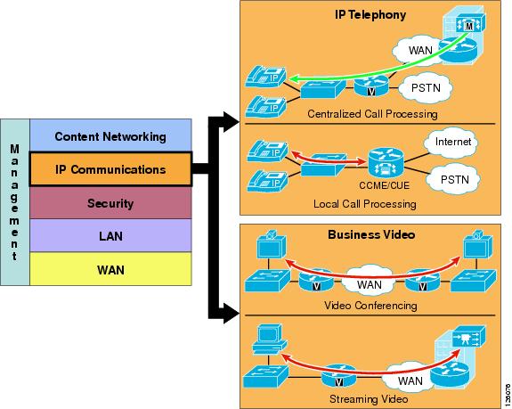
IP Communications Services Overview
IP telephony and business video are IP communications services used between users to carry out day-to-day business, as shown in Figure 1-12.
Figure 1-12 IP Communications Services
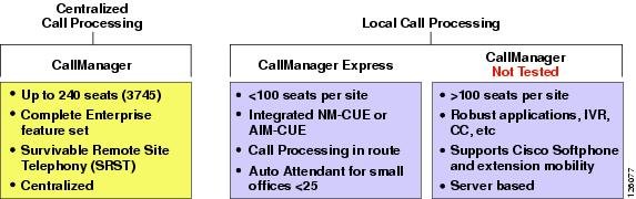
Call Processing Deployment Models
This design guide examines two deployment models: Centralized Call Processing and Local Call Processing. The call processing models tested depended on the office type: branch or autonomous office. The branch office used CallManager deployed with Centralized Call Processing, and the autonomous office used CallManager Express coupled with Unity Express for voice mail.
Figure 1-13 shows the general positioning of the two call processing methods discussed in this design guide.
Figure 1-13 IP Telephony Call Processing Positioning
The choice of whether to adopt a centralized call processing or distributed local call processing approach for a given site depends on a number of factors such as the following:
•![]() IP WAN bandwidth
IP WAN bandwidth
•![]() One-way delay to remote sites
One-way delay to remote sites
•![]() Criticality of the voice network
Criticality of the voice network
•![]() Feature set needs
Feature set needs
•![]() Scalability
Scalability
•![]() Ease of management
Ease of management
•![]() Cost
Cost
If a distributed local call processing model is deemed more suitable for customer business needs, the choices include installing a local Cisco CallManager server or running the Cisco CallManager Express on the branch router. This design guide focuses on the use of Cisco CallManager Express for Local Call Processing option for the office.
For more detailed information on designing IP telephony networks, see the following URL: http://www.cisco.com/en/US/products/ps6788/Products_Sub_Category_Home.html.
Centralized Call Processing
Centralized Call Processing is primarily used to serve branch offices where a centralized CallManager cluster and Unity Voice Mail system resides in the headquarters site, and provides all the call processing and voice mail services for the remote IP phones located in the branch office. (See Figure 1-14.)
Figure 1-14 Centralized Call Processing
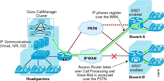
This call processing model eases branch deployment where the enterprise simply connects IP phones to the branch LAN and the phones then register to the CallManager cluster over the WAN. When registered, the IP phone automatically downloads its pre-configured profile and is ready to use. The access router is configured with the Survivable Remote Site Telephony (SRST) feature to provide backup call processing in case contact is lost to the CallManager cluster; for example, during WAN failure.
Another important consideration when deploying Centralized Call Processing is CAC, which limits the number of calls that may be placed over the WAN to maintain consistent high quality voice. This requires the proper provisioning of QoS on the WAN interface, and the configuration of CallManager such that call attempts that exceed the number of calls for which the WAN is provisioned receive a busy signal. CAC and WAN QoS ensure high voice quality for calls placed over the WAN in the Centralized Call Processing deployment model.
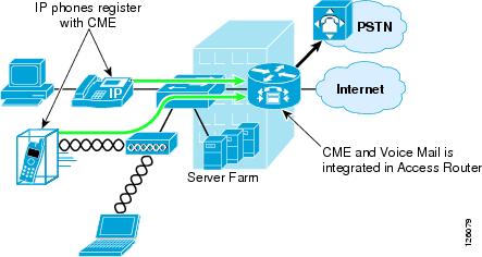
Local Call Processing
Local Call Processing is used in the autonomous office where CallManager Express, a software feature in the access router, provides the local call processing and the Unity Express hardware module, NM-CUE, provides the local voice mail and auto-attendant services. (See Figure 1-15).
Figure 1-15 Local Call Processing
Business Ready Branch Solution Summary
This chapter has presented an overview of the many services that may be deployed in the Business Ready Branch or autonomous Business Ready Office. As mentioned previously, this design guide covers only the integration of IP telephony and security services within the access router. Chapter 2, "Planning and Designing the Business Ready Branch Solution," discusses considerations when planning and designing an office network, Chapter 3, "Choosing a Branch Office Platform," explains how to choose the right platform for your office network, and Appendix A, "Sample Business Ready Branch Configuration Listings," provides a sample configuration listing.
 Feedback