Table Of Contents
Installing Memory and Power Over Ethernet in Cisco 880 Series Integrated Services Routers
Installing Power Over Ethernet
Installing Memory and Power Over Ethernet in Cisco 880 Series Integrated Services Routers
Warning
Before working on a system that has an on/off switch, turn OFF the power and unplug the power cord. Statement 1
This document describes how to install memory and Power over Ethernet (PoE) in a Cisco 880 Series Integrated Services Router (ISR). It contains the following sections:
•
Installing Power Over Ethernet
Note
Memory and PoE are the only upgradable options in the Cisco 880 Series ISR. Do not remove or install any other internal module.
Safety Warnings
Warning
This equipment must be grounded. Never defeat the ground conductor or operate the equipment in the absence of a suitably installed ground conductor. Contact the appropriate electrical inspection authority or an electrician if you are uncertain that suitable grounding is available. Statement 1024
Warning
Do not work on the system or connect or disconnect cables during periods of lightning activity. Statement 1001
Warning
Read the installation instructions before connecting the system to the power source. Statement 1004
Warning
Before working on equipment that is connected to power lines, remove jewelry (including rings, necklaces, and watches). Metal objects will heat up when connected to power and ground and can cause serious burns or weld the metal object to the terminals. Statement 43
Warning
Hazardous network voltages are present in WAN ports regardless of whether power to the unit is OFF or ON. To avoid electric shock, use caution when working near WAN ports. When detaching cables, detach the end away from the unit first. Statement 1026
Installing Main Memory
This section contains the following information:
Items Shipped
Table 1 shows the items shipped with a DIMM unit.
Table 1 Items and Their Quantities Shipped with a DIMM Unit
Item QuantityMemory module
1
ESD wrist strap
1
Installation Procedure
To install a DIMM in a Cisco 880 series ISR, follow these steps:
Step 1
Open the chassis according to the instructions in the "Opening the Chassis" section
Step 2
Locate the DIMM socket on the system board. See Figure 1 for the location of the DIMM socket.
Figure 1 DIMM Socket Location
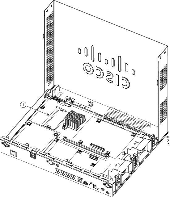
Step 3
Remove any existing DIMM by gently pulling the spring-loaded clips on the end of the socket far enough to release the DIMM, then gently pulling the DIMM up and away from the socket. See Figure 2.
Figure 2 Removing a DIMM
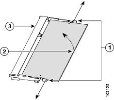
Step 4
Align the DIMM to the DIMM socket and insert the DIMM into the DIMM socket at a 45-degree angle, as shown in Figure 3.
Figure 3 Installing a DIMM
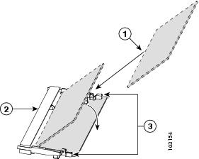
Step 5
Gently push the DIMM down toward the system board, as shown in Figure 3, until it snaps into the spring-loaded clips.
Step 6
Close the chassis according to the instructions in "Closing the Chassis" section.
Installing Power Over Ethernet
This section contains the following information:
Items Shipped
The PoE option for the Cisco 880 series ISR includes a PoE card, which must be installed inside the router, and an external power supply.
Table 2 lists the items shipped with a PoE module.
Table 2 Items and Their Quantities Shipped with a PoE Module
Item QuantityPoE PCBA
1
48-V PoE power supply adapter
1
Power supply cable
1
Standoffs
3
Screws
3
ESD wrist strap
1
Installation Procedure
Warning
Installation of the equipment must comply with local and national electrical codes. Statement 1074
Warning
Voltages that present a shock hazard may exist on Power over Ethernet (PoE) circuits if interconnections are made using uninsulated exposed metal contacts, conductors, or terminals. Avoid using such interconnection methods, unless the exposed metal parts are located within a restricted access location and users and service people who are authorized within the restricted access location are made aware of the hazard. A restricted access area can be accessed only through the use of a special tool, lock and key or other means of security. Statement 1072
To install the power supply card, perform the following steps:
CautionEnsure that the PoE power supply is not connected to the back of the router prior to installation of the PoE card. Failure to do so may result in damage to the PoE card or to the router.
Step 1
Open the chassis according to the instructions in "Opening the Chassis" section.
Step 2
Locate the three metal standoff holes on the system board. See Figure 4 for the location of the PoE connector. Two standoff holes are identified by a star pattern surrounding the hole; the third hole has a screw attached to it.
Figure 4 PoE Connector
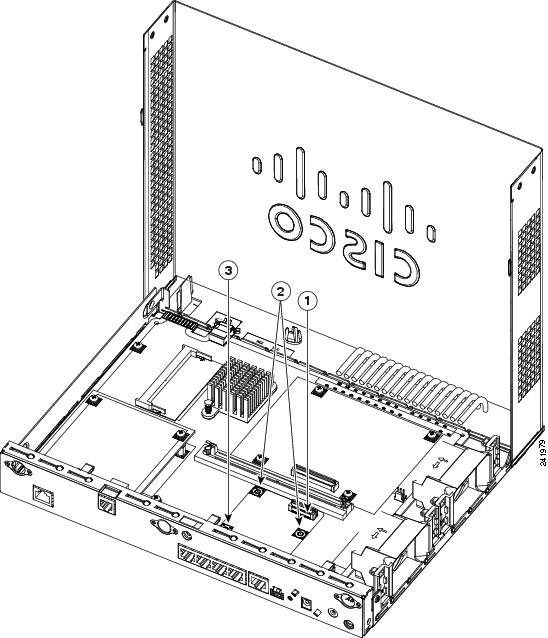
Step 3
Remove the screw from the third hole.
Step 4
Install the three metal standoffs, provided in the accessory kit, into the three standoff holes, as shown in Figure 5. Use a 1/4-inch nut driver to tighten the standoffs.
CautionMake sure that the standoffs are straight when installed. Tighten them gently but firmly. The shoulder of each standoff must be seated tightly against the system board.
Figure 5 Installing the Power over Ethernet Card
1
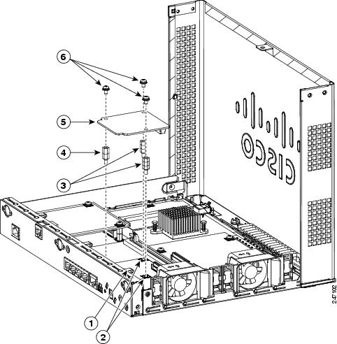
Standoff hole without star pattern
4PoE card
2Standoff holes with star pattern
5Screws
3Metal standoffs
CautionWhen installing the PoE card, ensure that the card is installed in the proper direction. Improper installation will damage the PoE card. Installation of the PoE card requires the installation of three metal standoffs, to which the card is then secured by using three screws. Be sure to use all three screws to ensure that the card is installed properly.
Tip
If the card is not installed in the correct direction, the three screw holes will not match up with the three metal standoffs.
Step 5
Place the PoE card on top of the three metal standoffs, lining up the screw holes in the PoE card with the metal standoffs.
Step 6
Push the PoE card down towards the system board until it is firmly fixed into the PoE connector.
Step 7
Insert the screws provided in the accessory kit through the PoE card and into the metal standoffs. See Figure 5. Carefully tighten the screws with a Phillips screwdriver.
Step 8
Close the router (see Closing the Chassis), and then connect the PoE power supply to an AC power outlet. To connect the PoE power supply to an AC power outlet, see the Cisco 860 and Cisco 880 Series Hardware Installation Guide, Connecting Power over Ethernet.
Opening the Chassis
To open the chassis, you will need a number-2 Phillips screwdriver, a wrist strap, and an antistatic mat.
Warning
During this procedure, wear grounding wrist straps to avoid ESD damage to the card. Do not directly touch the backplane with your hand or any metal tool, or you could shock yourself. Statement 94
Follow these steps to open the chassis:
Step 1
Disconnect the power supply cable.
Step 2
Disconnect all cables from the router back panel.
Step 3
Use the number-2 Phillips screwdriver to remove the screws at the middle on the back panel, and at the sides of the router. Figure 6 shows the location of the screws. The screws are in the same location on all Cisco 880 series ISRs.
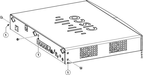
Figure 6 Chassis Screws Locations
Step 4
Place your hand on both sides of the router where the screws were located. With your fingers gently pry the chassis cover outward and away from the router, and lift the chassis cover up. The front end of the chassis cover will remain attached to the chassis. Figure 7 shows how to open the chassis.
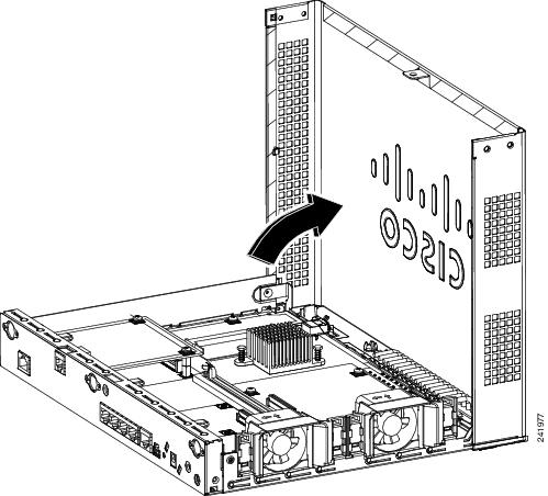
Figure 7 Opening the Chassis
Step 5
Place the router bottom on an antistatic mat.
Closing the Chassis
To close the chassis, you will need a number-2 Phillips screwdriver and a wrist strap.
Warning
During this procedure, wear grounding wrist straps to avoid ESD damage to the card. Do not directly touch the backplane with your hand or any metal tool, or you could shock yourself. Statement 94
To close the chassis, follow these steps:
Step 1
Flip the chassis cover down. The cover should snap shut. Figure 8 shows how to close the chassis.
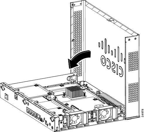
Figure 8 Closing the Chassis
Step 2
Check that the screw holes are aligned.
Step 3
Use the number-2 Phillips screwdriver to install the screws.
CCDE, CCENT, Cisco Eos, Cisco Lumin, Cisco Nexus, Cisco StadiumVision, the Cisco logo, DCE, and Welcome to the Human Network are trademarks; Changing the Way We Work, Live, Play, and Learn is a service mark; and Access Registrar, Aironet, AsyncOS, Bringing the Meeting To You, Catalyst, CCDA, CCDP, CCIE, CCIP, CCNA, CCNP, CCSP, CCVP, Cisco, the Cisco Certified Internetwork Expert logo, Cisco IOS, Cisco Press, Cisco Systems, Cisco Systems Capital, the Cisco Systems logo, Cisco Unity, Collaboration Without Limitation, EtherFast, EtherSwitch, Event Center, Fast Step, Follow Me Browsing, FormShare, GigaDrive, HomeLink, Internet Quotient, IOS, iPhone, iQ Expertise, the iQ logo, iQ Net Readiness Scorecard, iQuick Study, IronPort, the IronPort logo, LightStream, Linksys, MediaTone, MeetingPlace, MGX, Networkers, Networking Academy, Network Registrar, PCNow, PIX, PowerPanels, ProConnect, ScriptShare, SenderBase, SMARTnet, Spectrum Expert, StackWise, The Fastest Way to Increase Your Internet Quotient, TransPath, WebEx, and the WebEx logo are registered trademarks of Cisco Systems, Inc. and/or its affiliates in the United States and certain other countries.
All other trademarks mentioned in this document or Website are the property of their respective owners. The use of the word partner does not imply a partnership relationship between Cisco and any other company. (0805R)
Any Internet Protocol (IP) addresses used in this document are not intended to be actual addresses. Any examples, command display output, and figures included in the document are shown for illustrative purposes only. Any use of actual IP addresses in illustrative content is unintentional and coincidental.
© 2008 Cisco Systems, Inc. All rights reserved.


