- Chassis Views
- Locating the Serial Number, PID, VID and CLEI
- Hardware Features
- Slot, Port, and Interface Information
- LED Indicators
- Specifications
- Periodic Inspection and Cleaning
Overview of the Routers
Cisco Integrated Services Routers Generation 2 (ISR G2) offer data functionality through Gigabit Ethernet ports and security functionality with a virtual private network (VPN) accelerator on the motherboard. Additional security features are available with add-on hardware and software.
Cisco 2900 series and Cisco 3900 series routers also provide voice IP telephony with digital signal processor (DSP) capability; and voice gateway, DSP farm, IP-to-IP gateway, Cisco Unified Communications Manager Express (CUCME) via Cisco IOS. Cisco Unity Express (CUE) is provided through the use of add-on hardware.
This series of ISRs have new slots that support next generation Enhanced High-Speed WAN Interface Cards (EHWICs), Internal Services Modules (ISMs), Packet Voice Data Modules (PVDM3s), Service Modules (SMs), and Services Performance Engines (SPEs).
Access to the Cisco Multi-Gigabit Fabric (MGF) facilitates connection between switch ports on the ISR without utilizing all of the external ports. A logical GE interface on the ISR connects external and internal modules through the MGF for improved LAN and WAN switching.
|
|
|
|---|---|
Chassis Views
This section contains views of the front and back panels of the Cisco 2900 series and Cisco 3900 series routers, showing locations of the power and signal interfaces, module slots, status indicators, and chassis identification labels.

Note![]() Routers support the following slot types: Service Modules (SMs), Enhanced High-Speed Interface Card (EHWICs), high-speed WAN interface cards (HWICs), voice WAN interface cards (VWICs), WAN interface cards (WICs), Internal Services Modules (ISMs), and packet voice DSP modules (PVDM3s). However, some router models do not support all of these media types. See the router model descriptions for more information.
Routers support the following slot types: Service Modules (SMs), Enhanced High-Speed Interface Card (EHWICs), high-speed WAN interface cards (HWICs), voice WAN interface cards (VWICs), WAN interface cards (WICs), Internal Services Modules (ISMs), and packet voice DSP modules (PVDM3s). However, some router models do not support all of these media types. See the router model descriptions for more information.
Cisco 2901 Chassis
Figure 1-1— Front panel
Figure 1-2— Back panel
Figure 1-3— Back panel LEDs
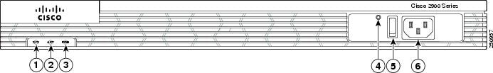
Figure 1-1 Front Panel of the Cisco 2901 Router
|
|
SYS1 |
|
ACT2 |
|
|
POE3 |
|
AC OK4 (only on AC PS, not AC-POE PS) |
|
|
|
|
4.LED goes off if the AC power fails or is disconnected. It does not go on and off with the power switch. |
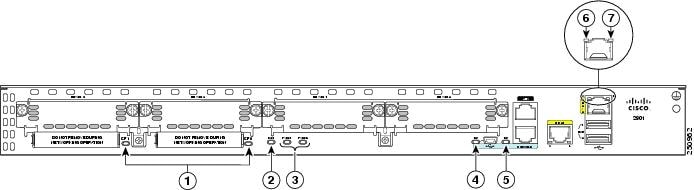
Figure 1-2 Back Panel Slots and Connectors of the Cisco 2901 Router

|
|
EHWIC slots 5 0, 1, 2, and 3 (0, Far right) |
|
USB6 serial port |
|
|
|
||
|
|
|
||
|
|
|
||
|
|
CompactFlash7 0 and 1 |
|
|
5.DW-EHWICs can fit into slot 0 and 1, and into slot 2 and 3. EHWIC slots support HWIC, VIC, and WIC. 7.Only Advanced Capability CompactFlash (CF) purchased from Cisco operates in Cisco 2900 series and Cisco 3900 series ISRs. Legacy CF can impact and severely degrade performance in these routers. See the “Memory” section. When legacy CF is inserted, the following error message appears: WARNING: Unsupported compact flash detected. Use of this card during normal operation can impact and severely degrade performance of the system. Please use supported compact flash cards only. |
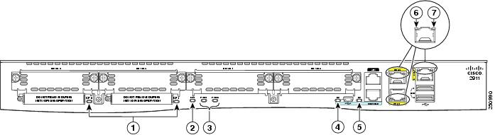
Figure 1-3 Back Panel LEDs of Cisco 2901 Router
|
|
|
ISM8 |
|
|
|
|
||
|
|
|
||
|
|
|
|
|
Cisco 2911 Chassis
Figure 1-4— Front panel
Figure 1-5— Back panel
Figure 1-6 — Back panel LEDs
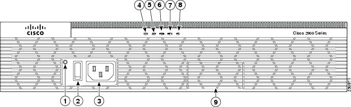
Figure 1-4 Front Panel of the Cisco 2911 Router
|
|
AC OK9 |
|
|
|
|
|
||
|
|
|
||
|
|
RPS10 |
|
PS11 |
|
|
|
|
9.LED goes off if the AC power fails or is disconnected. It does not go on and off with the power switch |
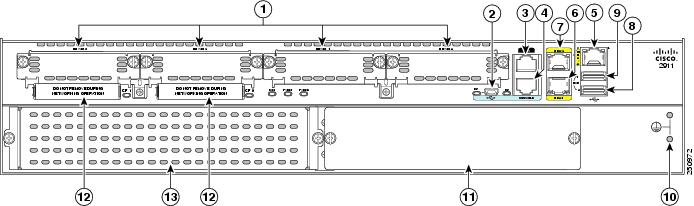
Figure 1-5 Back Panel of the Cisco 2911 Router
|
|
EHWIC slots12 0, 1, 2, and 3 (0, Far right) |
|
|
|
|
|
||
|
|
|
||
|
|
|
||
|
|
|
||
|
|
|
CompactFlash13 0 and 1 (0, Right) |
|
|
|
Service module14 slot 1 |
|
|
12.Double-wide EHWICs can fit into slot 0 and 1, and into slot 2 and 3. EHWIC slots support HWIC, VIC, and WIC. 13.Only Advanced Capability CompactFlash (CF) purchased from Cisco operates in Cisco 2900 series and Cisco 3900 series ISRs. Legacy CF can impact and several degrade performance in these routers. See the “Memory” section. When legacy CF is inserted, the following error message appears: WARNING: Unsupported compact flash detected. Use of this card during normal operation can impact and severely degrade performance of the system. Please use supported compact flash cards only. 14.Service module slots support legacy network modules when inserted with an adapter. See the router product page at Cisco.com for a list of supported modules. |
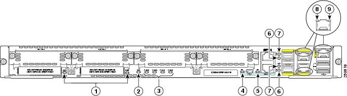
Figure 1-6 Back Panel LEDs of the Cisco 2911 Router
|
|
|
ISM15 |
|
|
|
|
||
|
|
|
||
|
|
|
|
|
Cisco 2921 and Cisco 2951 Chassis
Figure 1-7— Front panel
Figure 1-8— Back panel
Figure 1-9— Back panel LEDs
Figure 1-7 Front Panel of the Cisco 2921 and 2951 Routers

|
|
AC OK16 |
|
|
|
|
|
||
|
|
|
||
|
|
|
||
|
|
PS17 |
|
|
16.LED goes off if the AC power fails or is disconnected. It does not go on and off with the power switch. |
Figure 1-8 Back Panel Slots and Connectors on the Cisco 2921 and 2951 Routers

|
|
EHWIC slots18 0,1,2, and 3 (0, Far right) |
|
|
|
|
|
||
|
|
|
||
|
|
|
||
|
|
|
Service module slots19 SM1 and SM2 (1, Right on 2951), (1, left on 2921) |
|
|
|
CompactFlash20 0 and 1 (0, Right) |
|
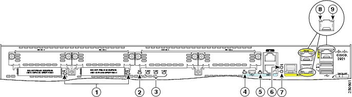
Figure 1-9 Back Panel LEDS of the Cisco 2921 and 2951 Routers
|
|
|
ISM21 |
|
|
|
|
||
|
|
|
SFP22 EN |
|
|
|
|
||
|
|
|
|
|
Cisco 3900 Series Chassis
Cisco 3900 series ISRs are shipped with Services Performance Engines (SPEs) pre-installed in the router. See the “Services Performance Engine” section for models and support information.
|
|
|
|---|---|
Figure 1-10 shows the Cisco 3925 and Cisco 3945 front panels.
Cisco 3925 and Cisco 3945 (SPE 100 and SPE 150)
- Back panel slots and connectors— Figure 1-11
- Back panel LEDs— Figure 1-12
Cisco 3925E and Cisco 3945E (SPE 200 or SPE 250)
- Back panel slots and connectors— Figure 1-13
- Back panel LEDs— Figure 1-14
Figure 1-10 Front Panel of the Cisco 3900 Series ISRs

|
|
AC OK23 |
|
|
|
|
|
||
|
|
|
||
|
|
|
|
23.LED goes off if the AC power fails or is disconnected. It does not go on and off with the power switch. |
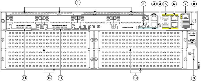
Figure 1-11 Back Panel Slots and Connectors for Cisco 3925 and 3945 (SPE 100 and SPE 150)
|
|
EHWIC slots24 0, 1, 2 and 3 (0, Far right) |
|
|
|
|
|
||
|
|
|
||
|
|
|
||
|
|
|
Cisco 3945 Service module slots25, 1 (Lower right), 2 (Lower left), 3 (Top right), and 4 (Top left) Cisco 3925 Service module slots26, 1 (Lower left)27, 2 (Top left) |
|
|
|
CompactFlash28 0 and 1 (0, Far right) |
|
|
24.Double-wide EHWICs can fit into slot 0 and 1, and into slot 2 and 3. EHWIC slots support HWIC, VIC, and WIC. 25.Service module slots support legacy network modules when inserted with an adapter. See the router product page at Cisco.com for a list of supported modules. See Table 1-5 for more router slot and module configurations. 26.Service module slots support legacy network modules when inserted with an adapter. See the router product page at Cisco.com for a list of supported modules. Double wide service modules install in the top slots. See Table 1-5 for more router slot and module configurations. 27.One single-wide in slot 1 (lower left). Lower right panel cannot be removed. See Table 1-5 for more router slot and module configurations. 28.Only Advanced Capability CompactFlash (CF) purchased from Cisco operates in Cisco 2900 series and Cisco 3900 series ISRs. Legacy CF can impact and severely degrade performance in these routers. See the “Memory” section. When legacy CF is inserted, the following error message appears: |
Figure 1-12 Back Panel LEDS on Services Performance Engine 100 and SPE 150
|
|
|
ISM29 |
|
|
|
|
||
|
|
|
||
|
|
|
||
|
|
|
|
|
Figure 1-13 Back Panel Slots/Connectors for Cisco 3925E and 3945E (SPE 200 or SPE 250)
|
|
EHWIC slots30 0,1, and 2 (0, Far right) |
|
|
|
|
|
||
|
|
|
||
|
|
|
||
|
|
|
Cisco 3945 Service module slots31, 1 (Lower right), 2 (Lower left), 3 (Top right), and 4 (Top left) Cisco 3925 Service module slots32, 1 (Lower left)33, 2 (Top left) |
|
|
|
CompactFlash34 1 and 0 (0, Far right) |
|
|
30.Slot 0 supports WIC/VIC, HWIC, and EHWIC. 31.Service module slots support legacy network modules when inserted with an adapter. See the router product page at Cisco.com for a list of supported modules. See Table 1-5 for router slot and module configurations. 32.Service module slots support legacy network modules when inserted with an adapter. See the router product page at Cisco.com for a list of supported modules. See Table 1-5 for router slot and module configurations. 33.One single-wide in slot 1 (lower left). Lower right panel cannot be removed. See Table 1-5 for more router slot and module configurations. 34.Only Advanced Capability CF purchased from Cisco operates in Cisco 2900 series and Cisco 3900 series ISRs. Legacy CF will not operate in these routers. When legacy CF is inserted, the following error message appears: |

Figure 1-14 Back Panel LEDS on Services Performance Engine 200 and 250

|
|
|
||
|
|
|
||
|
|
|
||
|
|
|
Locating the Serial Number, PID, VID and CLEI
To obtain a software license, you need a product authorization key (PAK) and the unique device identifier (UDI) of the device where the license will be installed.
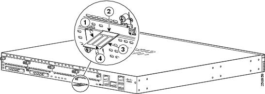
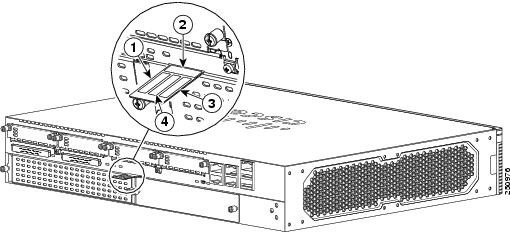
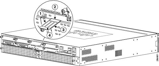
The serial number (SN), product ID (PID), version ID (VID), and Common Language Equipment Identifier (CLEI) are printed on a label on the back of the router or on a label tray located on the router chassis or motherboard. The UDI can be viewed using the show license udi command in privileged Exec mode in Cisco Internet Operating System (IOS) software. For additional information on the UDI or how to obtain a PAK, see the Cisco Software Activation on Integrated Services Routers document at Cisco.com.
The UDI has two main components:
Refer to these sections to locate labels on Cisco 2900 series and 3900 series ISRG2 routers:
Labels on Cisco 2901
Figure 1-15 shows the location of the labels on the Cisco 2901 router.
Figure 1-15 Labels Location on the Cisco 2901 Router
|
|
|
|---|---|
Labels on Cisco 2911
Figure 1-16 shows the location of the labels on the Cisco 2911 router.
Figure 1-16 Labels Location on the Cisco 2911 Router
|
|
|
|---|---|
Labels on Cisco 2921 and Cisco 2951
Figure 1-17 shows the location of the labels on the Cisco 2921 and Cisco 2951 routers.
Figure 1-17 Label Location on the Cisco 2921 and Cisco 2951 Routers
|
|
|
|---|---|
Labels on Cisco 3925 and Cisco 3945
Figure 1-18 shows the two locations where labels are located on Cisco 3900 ISRs. There are labels on the router chassis and on the Services Performance Engine (SPE).
Note![]() Use the serial number on the SPE label to obtain a PAK.
Use the serial number on the SPE label to obtain a PAK.
Figure 1-18 Labels Location(s) on Cisco 3900 ISRs
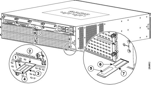
Table 1-3 Labels on Cisco 3900 Routers and SPE
|
|
|
|---|---|
|
|
|
|
|
|
|
|
|
|
|
|
|
|
|
|
|
|
|
|
For Additional Help Locating Labels on the Router
Use the Cisco Product Identification (CPI) tool to find labels on the router. It provides detailed illustrations and descriptions of where the labels are located on Cisco products. It includes the following features:
- A search option that allows browsing for models by using a tree-structured product hierarchy
- A search field on the final results page that makes it easier to look up multiple products
- End-of-sale products clearly identified in results lists
The tool streamlines the process of locating serial number labels and identifying products. Serial number information expedites the entitlement process and is important for access to support services.
The Cisco Product Identification tool can be accessed at the following URL:
Hardware Features
This section describes the hardware features in Cisco 2900 series and Cisco 3900 series routers.
- Built-in Interface Ports
- Removable and Interchangeable Modules and Cards
- Packet Voice Data Modules
- Power Supplies
- Module and Router Power Consumption
- Fans, Ventilation, and Airflow
- Real-Time Clock
- Secure Key
- Cryptographic Accelerator
Built-in Interface Ports
Table 1-4 summarizes the interface ports built into the router chassis.
|
|
|
|||||
|---|---|---|---|---|---|---|
|
|
GE RJ-45 |
|
|
|
|
|
335 |
||||||
336 |
||||||
437 |
||||||
438 |
||||||
|
37.Four RJ-45 or three RJ-45 with one GE-SFP, or two RJ-45 with two GE SFP 38.Four RJ-45 or three RJ-45 with one GE-SFP, or two RJ-45 with two GE SFP |
Gigabit Ethernet Ports
There are two different types of Gigabit Ethernet (GE) ports available on Cisco 2900 series and Cisco 3900 series ISRs.
GE Ports
The GE RJ-45 copper interface ports support 10BASE-T, 100BASE-TX, and 1000BASE-T.
SFP Ports
The small-form-factor pluggable (SFP) ports support 1000BASE-LX/LH, 1000BASE-SX, 1000BASE-ZX, and Coarse Wavelength-Division Multiplexing (CWDM-8) modules, as well as 100Mbs SFP modules.
The SFP port shares the same physical port as an RJ-45 GE port. Table 1-4 shows the models that support SFP installation. The SFP port supports auto-media-detection, auto-failover and remote fault indication (RFI), as described in the IEEE 802.3ah specification.
Use the media-type {rj45{auto-failover}} | {sfp{auto-failover}} command to enable the auto-media-detection and auto-failover features. Use the Command Lookup Tool for details about this command.
The SFP port can be configured for the following behaviors:
USB Serial Console Port
The Mini-USB type B serial port has been enabled to perform management tasks on the router. To use this port, you must install a Windows USB device driver before establishing physical connectivity between a personal computer and the router. See the “Installing the Cisco Microsoft Windows USB Device Driver” section for driver installation instructions.
Removable and Interchangeable Modules and Cards
Table 1-5 summarizes the type of removable modules and cards that can be installed in the router to provide specific capabilities. Services Performance Engines (SPEs), Service Modules (SMs), and Enhanced High-Speed WAN Interface Cards (EHWICs) fit into external slots and can be removed or replaced without opening the chassis.
Internal Services Modules (ISMs), expansion DRAM memory modules and next-generation Packet Voice Data Modules (PVDM3s) plug into internal connectors inside the chassis. These modules can be removed and installed only by opening the chassis on the Cisco 3900 series, or sliding the motherboard out of the Cisco 3900 series.
Because of physical differences with the new slots, legacy network modules and legacy Service Modules require an adapter for installation.

Warning![]() Only trained and qualified personnel should be allowed to install, replace, or service this equipment. Statement 1030
Only trained and qualified personnel should be allowed to install, replace, or service this equipment. Statement 1030
Warning![]() This equipment must be installed and maintained by service personnel as defined by AS/NZS 3260. Incorrectly connecting this equipment to a general-purpose outlet could be hazardous. The telecommunications lines must be disconnected 1) before unplugging the main power connector or 2) while the housing is open, or both. Statement 1043
This equipment must be installed and maintained by service personnel as defined by AS/NZS 3260. Incorrectly connecting this equipment to a general-purpose outlet could be hazardous. The telecommunications lines must be disconnected 1) before unplugging the main power connector or 2) while the housing is open, or both. Statement 1043
See the Overview of Cisco Network Modules and Service Modules for Cisco Access Routers document for general information and single- and double-wide slot numbering.
See the Installing Cisco Network Modules in Cisco Access Routers document for instructions that describe how to install SMs, legacy network modules, and legacy Service Modules in the router.
See the Overview of Cisco Interface Cards for Cisco Access Routers for general interface card information.
See the Installing Cisco Interface Cards in Cisco Access Routers document, for instructions that describe how to install EHWICs and legacy interface cards in the router.
Note![]() See the router product page at Cisco.com for a list of supported network modules and interface cards for Cisco 2900 series and Cisco 3900 series ISRs.
See the router product page at Cisco.com for a list of supported network modules and interface cards for Cisco 2900 series and Cisco 3900 series ISRs.
Table 1-5 shows the number of internal and external slots on Cisco 2900 series and Cisco 3900 series ISRs. It also shows the number of EHWICs and SMs that are supported in the router slots at any time. Table 1-8 shows memory specifications by router.
|
|
|
|
|||
|---|---|---|---|---|---|
|
|
|
|
|
|
|
Services Performance Engine
Services Performance Engines (SPEs) are modular motherboards for Cisco 3900 series ISRs. The SPE includes PVDM3 slots and system memory slots, and the ISM slot. The Services Performance Engine provides a modular approach to system upgrades. Slide out the SPE from the router to replace internal modules, or to upgrade the SPE for improved router performance.
See the Removing and Replacing the Services Performance Engine for installation information.
Table 1-6 lists four SPE models that are supported on Cisco 3900 series routers. SPEs illustrations are shown in the “Chassis Views” section. SPEs come pre-installed in 3900 series routers, or they are purchased separately and installed in a 3900 series router. See the support table for more information.
|
|
|
|
|---|---|---|
Note![]() The SPE 200 and the SPE 250 include a cryptographic accelerator for improved security performance. See the “Cryptographic Accelerator” section for more information.
The SPE 200 and the SPE 250 include a cryptographic accelerator for improved security performance. See the “Cryptographic Accelerator” section for more information.
Service Modules
Service Modules (SM) are the largest modules on Cisco 2900 series and Cisco 3900 series ISRs. With the largest form-factor and power capacity, these modules deliver high-performance service applications. SMs are physically larger than legacy network modules, as a result, network modules require an adapter for installation. See the Installing Cisco Network Modules in Cisco Access Routers guide for installation instructions, http://www.cisco.com/en/US/docs/routers/access/interfaces/nm/hardware/installation/guide/InstNetM.html.
Enhanced High-Speed WAN Interface Cards
Enhanced High-Speed WAN Interface Card (EHWICs) are the latest generation of interface cards. EHWICs are installed in the EHWIC slot on the router. Legacy interface cards, such as WAN interface cards (WICs), voice interface cards (VICs), high-speed WAN interface cards (HWICs), double-width high-speed WAN interface cards (DHWICs), and (EHWICs) are supported in the EHWIC slot on the router.
Services Performance Engine 200 and Services Performance Engine 250 support the following legacy interface cards in the EHWIC slots. (See Table 1-7 .)
Table 1-7 EHWIC Support for SPE 200 and SPE 250
|
|
|
|
|---|---|---|
Integrated Service Modules
Internal Services Modules (ISM) supersede advanced integration modules (AIM) on Cisco 2900 series and Cisco 3900 series ISRs. The ISM is larger in size than the AIM. Due to these physical differences, the AIM does not fit into the ISM slot and is no longer supported on Cisco 2900 series and Cisco 3900 series ISRs.
Packet Voice Data Modules
The Packet Voice Data Modules (PVDM3s) are the latest generation of PVDMs. First-generation PVDM-I cards are not supported in the PVDM3 slots. Due to physical differences, PVDM2s require an adapter for installation in the PVDM3 slot. See the “Installing and Removing PVDM2s” section for installation instructions.
Note![]() PVDM2 cards cannot be mixed with PVDM3s.
PVDM2 cards cannot be mixed with PVDM3s.
Memory
Cisco 2900 series and Cisco 3900 series routers contain the following types of memory:
- DRAM—Stores the running configuration and routing tables and is used for packet buffering by the network interfaces. Cisco IOS software executes from DRAM memory. Supported module types are Unregistered Dual In-Line Memory Module (UDIMM) and very low profile registered DIMM (VLP RDIMM).
Note![]() UDIMMs and VLP RDIMMs are not interchangeable.
UDIMMs and VLP RDIMMs are not interchangeable.
- Boot/NVRAM—256K of internal non-volatile memory. Stores the bootstrap program (ROM monitor), the configuration register, and the startup configuration.
- Flash memory—External flash memory. Stores the operating system software image. Each model supports 2 external CompactFlash 4-GB memory cards provide a maximum 8-GB of CompactFlash.
Note![]() You must use Cisco-qualified CompactFlash cards supporting True IDE PIO Mode 6 and True IDE Multiword DMA Mode 4 as defined in CompactFlash Specification Revision 4.1 of the CompactFlash Association. Use of any other cards during normal network operation can affect system performance.
You must use Cisco-qualified CompactFlash cards supporting True IDE PIO Mode 6 and True IDE Multiword DMA Mode 4 as defined in CompactFlash Specification Revision 4.1 of the CompactFlash Association. Use of any other cards during normal network operation can affect system performance.
Table 1-8 summarizes the memory options for Cisco 2900 series and Cisco 3900 series routers. Default memory represents the minimum usable RAM. You can install additional RAM up to the maximum amount.
Expansion memory modules are UDIMMs or VLP RDIMMs with error correction code (ECC). All onboard RAM uses ECC.
Note![]() The current IOS supports only 2 GB of DRAM, although; the hardware supports more. Future IOS versions may support more than 2 GB of DRAM.
The current IOS supports only 2 GB of DRAM, although; the hardware supports more. Future IOS versions may support more than 2 GB of DRAM.
Power Supplies
Cisco 2900 series and Cisco 3900 series ISRs support a variety of power supply configurations. All power supplies are field replaceable and externally accessible with the exception of the Cisco 2901 ISR. The Cisco 2901 ISR has an internal power supply, which requires removing the cover for replacement.
If configured with dual power supplies or an Redundant power supplies (RPS), the power supplies are hot swappable. RPSs require an RPS adapter. There are two versions of the RPS adapter, one for the Cisco 2911 and one for the Cisco 2921 and 2951. Both use the Cisco Redundant Power System 2300.
Configurations include AC and DC (with and without IP), Dual DC, internal POE, and POE boost.
- Table 1-9 summarizes the power options.
- Table 1-10 shows POE power rates.
|
|
|
|
|
|
|
|
|
|
|
|
|
|---|---|---|---|---|---|---|---|---|---|---|---|
|
|
||||||||
|---|---|---|---|---|---|---|---|---|
|
|
|
|
|
|
|
|
|
|
Module and Router Power Consumption
Cisco 2900 series and Cisco 3900 series ISRs have energy efficiency features that reduce power consumption. Some of the energy efficiency features are controlled by the hardware, whereas other energy efficiency features are controlled by the software.
Fans, Ventilation, and Airflow
The Cisco 2911 and Cisco 3900 series ISRs have optional fan filters that are easy to replace. The filters may be used to meet Network Equipment Building Systems (NEBS) requirements, or to operate in dusty environments. When a filter becomes dirty, discard it and replace it with a new one. See the “Replacing a Fan Tray or Air Filter” section.
Fan speeds are controlled by the fan speed controller circuitry. To minimize noise, the fans operate at one of several predetermined speeds and are dependent on the input ambient air temperature.
- shows Cisco 2901 airflow.
- Figure 1-20 shows Cisco 2911 airflow.
- Figure 1-21 shows Cisco 2921 and 2951 airflow.
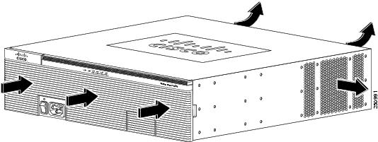
- shows the Cisco 3900 series standard (non NEBS) airflow configuration. For NEBS, the airflow is reversed.
- shows the Cisco 3900 series standard NEBS airflow configuration.
Figure 1-19 Cisco 2901 Router Airflow
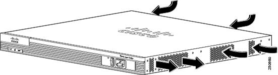
Figure 1-20 Cisco 2911 Router Airflow
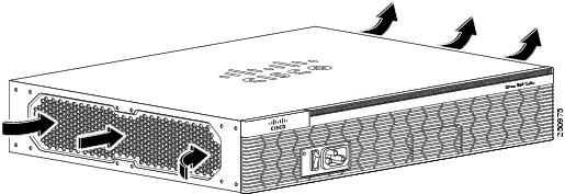
Figure 1-21 Cisco 2921 and Cisco 2951 Router Airflow
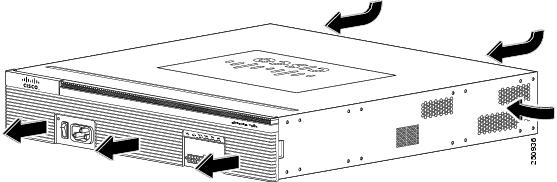
Figure 1-22 Cisco 3900 Series (Non NEBS) Router Airflow
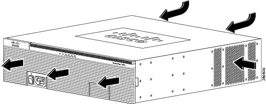
Figure 1-23 Cisco 3900 Series NEBS Router Airflow
Real-Time Clock
Upon system power up, the internal real-time clock with battery backup provides the system software with the time of day. This allows the system to verify the validity of the certification authority (CA) certificate. The Cisco 2900 and Cisco 3900 series routers have a lithium battery. This battery lasts for the life time of the router under the operating environmental conditions specified for the router and is not field-replaceable.
Note![]() If the lithium battery in a Cisco 2900 or Cisco 3900 series ISR should fail, the router must be returned to Cisco for repair.
If the lithium battery in a Cisco 2900 or Cisco 3900 series ISR should fail, the router must be returned to Cisco for repair.
Although the battery is not intended to be field-replaceable, the following warning must be heeded:
Warning![]() There is the danger of explosion if the battery is replaced incorrectly. Replace the battery only with the same or equivalent type recommended by the manufacturer. Dispose of used batteries according to the manufacturer's instructions. Statement 1015
There is the danger of explosion if the battery is replaced incorrectly. Replace the battery only with the same or equivalent type recommended by the manufacturer. Dispose of used batteries according to the manufacturer's instructions. Statement 1015
Secure Key
A hardware secure key storage unit is provided on the Cisco 3925 and Cisco 3945 routers to safely store passwords and credentials. The secure key storage unit is a self-contained tamper-resistant computer key-store that acts as a black box for credential storage by accepting credentials and never returning them.
Cryptographic Accelerator
Cisco 3925E and Cisco 3945E ISRs ship with a Services Performance Engine that includes an onboard cryptographic accelerator. It shares security processing for SSLVPN and IPSec. By default, acceleration of SSL is disabled so IPSec performance is maximized.
If you want to set up the router as an SSLVPN gateway, enable the SSLVPN feature with the
crypto engine accelerator bandwidth-allocation ssl fair command. To learn more about the cryptographic accelerator, see the Configuring the Security Features module in the Cisco 3900 series, 2900 series, and 1900 series Integrated Services Routers Software Configuration Guide at Cisco.com.
Slot, Port, and Interface Information
Table 1-11 and Table 1-12 show slot, port, and interface numbering ranges.
On the Cisco 2901 router, the numbering format for slots and ports is defined as follows: interface type 0/slot/port. “0” indicates slots that are built into the chassis of a router. On the Cisco 2901 router, all slots begin with “0,” because all slots are built into the chassis. On the Cisco 2911, 2921, 2951, and Cisco 3900 series routers, some slots are built into the chassis and some are external.
Slots that are part of a network module or an extension voice module have numbers that begin with “1” or “2,” respectively. See the module documentation for more information.
|
|
|
|
|
|
|---|---|---|---|---|
interface 0/0/ port |
interface 0/0/ port |
interface 0/0/ port |
||
interface 1/ port51 |
||||
interface1-2/wic- interface1-4/wic- |
|
|
|
|
|---|---|---|
Interface card (DW-EHWIC, EHWIC,HWIC, HWIC-D, WIC, VWIC, VIC) plugged directly into an EHWIC slot |
Interface-type 0 / interface-card-slot58 / port |
interface serial 0/x/y |
Interface card (WIC, VWIC, VIC) plugged into a service or network module |
Interface-type 1 60 / interface-card-slot / port |
controller t1 1/x/y |
Built into a service or network module (NME, NME-X, NMD, NME-XD) |
Interface-type 1 5 / port |
interface gi 1/x |
| FXS/DID port numbers 0 to 7 are built into the EVM. |
||
Voice port in a BRI expansion module (internal slot) in an extension voice module (EVM) |
||
BRI interface in a BRI expansion module (internal slot) in an extension voice module |
Port numbers are 0 to 3 if one expansion module is installed. Port numbers are 0 to 7 if two expansion modules are installed. |
Note![]() On the Cisco 2911, 2921, 2951 routers and Cisco 3900 series routers the interface numbering scheme is the same for asynchronous interfaces as for other types of interfaces. To configure the line associated with an async interface, use the interface number to specify the async line. For example, line 0/3/0 specifies the line associated with interface serial 0/3/0 on an WIC-2A/S in slot 3. Similarly, line 1/22 specifies the line associated with interface async 1/22 on an NM-32A in network module slot 1.
On the Cisco 2911, 2921, 2951 routers and Cisco 3900 series routers the interface numbering scheme is the same for asynchronous interfaces as for other types of interfaces. To configure the line associated with an async interface, use the interface number to specify the async line. For example, line 0/3/0 specifies the line associated with interface serial 0/3/0 on an WIC-2A/S in slot 3. Similarly, line 1/22 specifies the line associated with interface async 1/22 on an NM-32A in network module slot 1.
LED Indicators
Table 1-13 summarizes the LED indicators that are located on the router bezel or chassis, but not on the removable modules or interface cards.
For descriptions of LEDs in removable modules and interface cards, see the applicable documentation for those products.
For LED troubleshooting information, including possible trouble causes and corrective actions, see Table 1-13 .
|
|
|
|
|
|
|---|---|---|---|---|
| AC OK61 |
||||
Solid or blinking indicates packet activity between the forwarding and routing engine and any I/O port. |
||||
Blinking frequency indicates port speed. See the definition for the S LED. |
||||
Flash memory is being accessed; do not eject the CompactFlash memory card. |
||||
Flash memory is not being accessed; okay to eject the CompactFlash memory card. |
||||
|
61.LED goes off if the AC power fails or is disconnected. It does not go on and off with the switch. |
Specifications
The following tables provide ISR specifications.
- Cisco 2901— Table 1-14
- Cisco 2911— Table 1-15
- Cisco 2921— Table 1-16
- Cisco 2951— Table 1-17
- Cisco 3900 series— Table 1-18
|
|
|
|---|---|
|
|
|
1.75 x 17.25 x 17.3 in. (44.5 x 438.2 x 439.4 mm), 1 RU height |
|
|
|
|
|
|
|
One RJ-45 connector and one mini USB Type B, USB 2.0 compliant |
|
Two USB Type A, USB 2.0 compliant, 2.5 W (500 mA) max.62 |
|
Two RJ-45 connectors (GE0/0, GE0/1), auto-MDIX63 |
|
|
|
|
|
|
|
|
|
|
|
|
|
IEC 60950-1, Safety of information technology equipment EN 60950-1, Safety of information technology equipment UL 60950-1, Standard for safety for information technology equipment [US] CAN/CSA C22.2 No. 60950-1, Safety of information technology equipment including electrical business equipment [Canada] IEC60950, 2nd Edition [Mexico] For detailed compliance information, see the Regulatory Compliance and Safety Information for Cisco 2900 Series Integrated Services Router document. |
|
CISPR24 ITE-Immunity characteristics, Limits and methods of measurement EN 55024 ITE-Immunity characteristics, Limits and methods of measurement EN50082-1 Electromagnetic compatibility - Generic immunity standard - Part 1 EN300-386 Electromagnetic compatibility for TNE For detailed compliance information, see the Regulatory Compliance and Safety Information for Cisco 2900 Series Integrated Services Routers document. |
|
| CFR47, Part 15, Subpart B, class A Harmonic Current Emission Voltage Fluctuation and Flicker For detailed compliance information, see the Regulatory Compliance and Safety Information for Cisco 2900 Series Integrated Services Router document. |
|
|
62.480 Mb/s individually, bandwidth is shared when both are used. |
|
|
|
|---|---|
3.5 x 17.25 x 12.0 in. (88.9 x 438.2 x 304.8mm), 2 RU height |
|
|
|
|
30 A maximum at 115 VAC 60 Hz, 60 A maximum at 230 VAC 50 Hz |
|
|
|
|
One RJ-45 connector and one mini USB Type B, USB 2.0 compliant |
|
Two USB Type A, USB 2.0 compliant, 2.5 W (500 mA) max.64 |
|
Three RJ-45 connectors (GE0/0, GE0/1, GE0/2), auto-MDIX65 |
|
|
|
|
Operating temperature up to 5906 ft (1800 m) elevation, with filter |
|
Operating temperature up to 9843 ft (3000 m) elevation, with or without filter |
|
|
|
|
|
|
|
|
|
|
IEC 60950-1, Safety of information technology equipment EN 60950-1, Safety of information technology equipment UL 60950-1, Standard for safety for information technology equipment [US] CAN/CSA C22.2 No. 60950-1, Safety of information technology equipment including electrical business equipment [Canada] IEC60950, 2nd Edition [Mexico] For detailed compliance information, see the Regulatory Compliance and Safety Information for Cisco 2900 Series Integrated Services Router document. |
|
CISPR24 ITE-Immunity characteristics, Limits and methods of measurement EN 55024 ITE-Immunity characteristics, Limits and methods of measurement EN 50082-1 Electromagnetic compatibility - Generic immunity standard - Part 1 EN 300-386 Electromagnetic compatibility for TNE For detailed compliance information, see the Regulatory Compliance and Safety Information for Cisco 2900 Series Integrated Services Router document. |
|
| CFR47, Part 15, Subpart B, class A Harmonic Current Emission Voltage Fluctuation and Flicker For detailed compliance information, see the Regulatory Compliance and Safety Information for Cisco 2900 Series Integrated Services Router document. |
|
|
64.480 Mb/s individually, bandwidth is shared when both are used. |
|
|
|
|---|---|
|
|
|
3.5 x 17.25 x 18.5 in. (88.9 x 438.2 x 469.9 mm), 2 RU height |
|
|
|
|
|
|
|
One RJ-45 connector and one mini USB Type B, USB 2.0 compliant |
|
Two USB Type A, USB 2.0 compliant, 2.5 W (500 mA) max.66 |
|
One RJ-45 connector supports an SFP module. When an SFP module is installed, the adjacent RJ-45 GE connector is disabled. |
|
|
|
|
|
|
|
|
|
|
|
|
|
IEC 60950-1, Safety of information technology equipment EN 60950-1, Safety of information technology equipment UL 60950-1, Standard for safety for information technology equipment [US] CAN/CSA C22.2 No. 60950-1, Safety of information technology equipment including electrical business equipment [Canada] IEC60950, 2nd Edition [Mexico] For detailed compliance information, see the Regulatory Compliance and Safety Information for Cisco 2900 Series Integrated Services Router document. |
|
CISPR24 ITE-Immunity characteristics, Limits and methods of measurement EN 55024 ITE-Immunity characteristics, Limits and methods of measurement EN 50082-1 Electromagnetic compatibility - Generic immunity standard - Part 1 EN 300-386 Electromagnetic compatibility for TNE For detailed compliance information, see the Regulatory Compliance and Safety Information for Cisco 2900 Series Integrated Services Routers document. |
|
| CFR47, Part 15, Subpart B, class A Harmonic Current Emission Voltage Fluctuation and Flicker For detailed compliance information, see the Regulatory Compliance and Safety Information for Cisco 2900 Series Integrated Services Router document. |
|
|
66.480 Mb/s individually, bandwidth is shared when both are used. |
|
|
|
|---|---|
|
|
|
3.5 x 17.25 x 18.5 in. (88.9 x 438.2 x 469.9 mm), 2 RU height |
|
|
|
|
|
|
|
One RJ-45 connector and one mini USB Type B, USB 2.0 compliant |
|
Two USB Type A, USB 2.0 compliant, 2.5 W (500 mA) max.67 |
|
One RJ-45 connectors supports an SFP module. When an SFP module is installed the adjacent RJ-45 GE connector is disabled. See Table 1-4 for a list of supported modules. |
|
|
|
|
|
|
|
|
|
|
|
|
|
IEC 60950-1, Safety of information technology equipment EN 60950-1, Safety of information technology equipment UL 60950-1, Standard for safety for information technology equipment [US] CAN/CSA C22.2 No. 60950-1, Safety of information technology equipment including electrical business equipment [Canada] IEC60950, 2nd Edition [Mexico] For detailed compliance information, see the Regulatory Compliance and Safety Information for Cisco 2900 Series Integrated Services Router document |
|
CISPR24 ITE-Immunity characteristics, Limits and methods of measurement EN 55024 ITE-Immunity characteristics, Limits and methods of measurement EN 50082-1 Electromagnetic compatibility - Generic immunity standard - Part 1 EN 300-386 Electromagnetic compatibility for TNE For detailed compliance information, see the Regulatory Compliance and Safety Information for Cisco 2900 Series Integrated Services Router document |
|
| CFR47, Part 15, Subpart B, class A Harmonic Current Emission Voltage Fluctuation and Flicker For detailed compliance information, see the Regulatory Compliance and Safety Information for Cisco 2900 Series Integrated Services Router document. |
|
|
67.480 Mb/s individually, bandwidth is shared when both are used. |
|
|
|
|---|---|
|
|
|
5.25 x 17.25 x 18.75 in. (133.4 x 438.2 x 476.2 mm), 3 RU height |
|
|
|
|
30 A maximum at 115 VAC 60 Hz, 60 A maximum at 230 VAC 50 Hz |
|
|
|
|
One RJ-45 connector and one mini USB Type B, USB 2.0 compliant |
|
Two USB Type A, USB 2.0 compliant, 2.5 W (500 mA) max.68 |
|
Three or Four RJ-45 connectors (GE0/0, GE0/1, GE0/2, GE0/3), auto-MDIX69. Note Cisco 3925E and Cisco 3945E routers have four RJ-45 connectors that support Gigabit Ethernet networks. |
|
Two RJ-45 connectors support SFP modules. When an SFP module is installed the adjacent RJ-45 GE connector is disabled. See Table 5-3 for a list of supported modules. |
|
|
|
|
|
|
|
|
|
|
|
|
|
IEC 60950-1, Safety of information technology equipment EN 60950-1, Safety of information technology equipment UL 60950-1, Standard for safety for information technology equipment [US] CAN/CSA C22.2 No. 60950-1, Safety of information technology equipment including electrical business equipment [Canada] IEC60950, 2nd Edition [Mexico] For detailed compliance information, see the Regulatory Compliance and Safety Information for Cisco 3900 Series Integrated Services Routers document. |
|
CISPR24 ITE-Immunity characteristics, Limits and methods of measurement EN 55024 ITE-Immunity characteristics, Limits and methods of measurement EN 50082-1 Electromagnetic compatibility - Generic immunity standard - Part 1 EN 300-386 Electromagnetic compatibility for TNE For detailed compliance information, see the Regulatory Compliance and Safety Information for Cisco 3900 Series Integrated Services Routers document. |
|
| CFR47, Part 15, Subpart B, class A Harmonic Current Emission Voltage Fluctuation and Flicker For detailed compliance information, see the Regulatory Compliance and Safety Information for Cisco 3900 Series Integrated Services Routers document. |
|
|
68.480 Mb/s individually, bandwidth is shared when both are used. |
Periodic Inspection and Cleaning
Periodic inspection and cleaning of the external surface of the router is recommended to minimize the negative impact of environmental dust or debris. The frequency of inspection and cleaning is dependent upon the severity of the environmental conditions, but a minimum of every six months is recommended. Cleaning involves vacuuming of router air intake and exhaust vents and replacement of air filters. See the “Fans, Ventilation, and Airflow” section and the “Replacing a Fan Tray or Air Filter” section.

 Feedback