- Contents
- Primary/Backup Deployment Using NAT/PAT and IPSec
- Primary/Backup Deployment using GRE Tunnels and IPSec
- Primary/Backup Deployment using GRE Tunnels, IPSec, and OSPF Routing
- DMVPN Deployment with IPSec and OSPF
- EzVPN Deployment with Primary and Backup Links
- NEMO Over 3G with CCOA-Only Mode
- 3G L2TP VPN Deployments
Advanced Network Deployment Scenarios
This chapter describes the advanced deployment scenarios. The configurations used for the deployment scenarios throughout this chapter are for GSM. The same configurations can be used for CDMA deployment scenarios, with slight modifications.
Contents
•![]() Primary/Backup Deployment Using NAT/PAT and IPSec
Primary/Backup Deployment Using NAT/PAT and IPSec
•![]() Primary/Backup Deployment using GRE Tunnels and IPSec
Primary/Backup Deployment using GRE Tunnels and IPSec
•![]() Primary/Backup Deployment using GRE Tunnels, IPSec, and OSPF Routing
Primary/Backup Deployment using GRE Tunnels, IPSec, and OSPF Routing
•![]() DMVPN Deployment with IPSec and OSPF
DMVPN Deployment with IPSec and OSPF
•![]() EzVPN Deployment with Primary and Backup Links
EzVPN Deployment with Primary and Backup Links
•![]() NEMO Over 3G with CCOA-Only Mode
NEMO Over 3G with CCOA-Only Mode
Primary/Backup Deployment Using NAT/PAT and IPSec
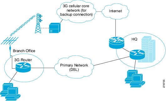
Figure 5-1 shows a deployment that uses the DSL interface as a primary link and the cellular interface as a backup link. It uses NAT/PAT and IPsec at a branch office for secure communication between the hosts on the branch office router and the hosts at the HQ site via a public network. This deployment also allows non-secure (non-IPsec) communication with the hosts on the Internet.
Figure 5-1 Primary/Backup Deployment Using NAT/PAT and IPSec
Configuration for the Branch Office Router
Example 5-1 Configuration for the Branch Office Router
The blue italicized text throughout this configuration is used to indicate comments and will not be seen when a normal console output is viewed. The bold text is used to indicate important commands to refer back to in case of an error. When debugging, ensure that all the commands in bold are the same in your console output.
Unless otherwise noted, the bold text refers to commands associated with the basic cellular configuration. The bold text is also used for other configurations such as the crypto IPsec configuration, the backup configuration, the IP SLA configuration, and the mobile IP configuration. Commands associated with each of these configurations are called out throughout the example for ease of reference when debugging.
!
! This configuration uses IP SLA, using reliable object tracking. This configuration is
! optional. It allows tracking the connectivity via the primary (DSL) interface using
! ICMP pings to some known IP destination address in the outside network via this
! primary interface. Failure to receive response to pings will cause the default route
! via the primary interface to be removed from the routing table and the default route
! (configured with a higher administrative distance) via the Cellular interface will
! become the effective path providing the connectivity via the backup path.
!
! Without this configuration it is still possible to achieve the primary/backup
! connectivity using the 'backup interface ...' command, which detects network
! connectivity failure at PPP/physical layer and causes switchover to occur to the
! backup (cellular) interface.
!
!
hostname branch-router
!
ip cef
!
ip dhcp excluded-address 10.4.0.254
!
! This command basically excludes the assignment of ip address 10.4.0.254 to any hosts
! since this is used as a default gateway address for connected host on VLAN 104 - Fast
! Ethernet ports 0/1/0 thru 0/3/0.
!
ip dhcp pool gsmpool
network 10.4.0.0 255.255.0.0
dns-server 66.209.10.201 66.102.163.231
default-router 10.4.0.254
!
! DHCP pool for the hosts connected to the VLAN 104 - Fast Ethernet ports 0/1/0
! thru 0/3/0
!
!
chat-script gsmscript "" "atdt*98*1#" TIMEOUT 20 "CONNECT"
!
! Chat script to dial out via cellular interface
!
!
username cisco privilege 15 secret 5 $1$ccw8$TFmKUmI4QVZhOMuxzq/SH/
!
track 234 rtr 1 reachability
!
! Configures tracked object number 234 to track for reachability using operation 1.
! The object is 'UP' if reachability condition is met.
! This is used for sending ping packets via the ATM DSL interface (used as a
! primary link) and monitoring the response to help determine if switchover (to
! cellular) is necessary in the event of no response.
!
crypto isakmp policy 1
encr 3des
authentication pre-share
!
! Defines the IKE policy (with priority 1), specifies 3DES during IKE negotiation and
! authentication as pre-shared, using pre-defined keys. The values for lifetime (set to
! 86,400 sec - one day), group (set to 768 bit Diffie-Hellman), and Hash (set to SHA-1)
! are set to their default values.
!
!
crypto isakmp key mykey address 20.20.241.234
!
! Defines the key (mykey) and the IP address of the gateway
! (IPsec peer) with which the Security Association will be set
!
crypto ipsec transform-set mytransformset ah-sha-hmac esp-3des
!
! Defines the transform set (mytransformset), which is an acceptable combination of
! security protocols, algorithms, and other settings to apply to IPsec-protected
! traffic.
!
crypto map gsm1 10 ipsec-isakmp
set peer 20.20.241.234
set transform-set mytransformset
match address 103
!
! Defines the crypto map gsm1
!
! crypto map specifies the traffic to be protected (using match address <access-list>
! command), the peer end-point to be used, and the transform set to use (mytransformset,
! defined earlier).
!
interface Loopback1
ip address 1.1.1.1 255.255.255.255
!
interface GigabitEthernet0/0
no ip address
shutdown
!
interface GigabitEthernet0/1
no ip address
shutdown
!
interface FastEthernet0/1/0
switchport access vlan 104
!
interface FastEthernet0/1/1
switchport access vlan 104
!
interface FastEthernet0/1/2
switchport access vlan 104
!
interface FastEthernet0/1/3
switchport access vlan 104
!
! Fast Ethernet ports used by DHCP Client hosts
!
interface ATM0/0/0
no ip address
ip virtual-reassembly
load-interval 30
no atm ilmi-keepalive
dsl operating-mode auto
!
! ATM (DSL) physical interface used as primary interface
!
interface ATM0/0/0.1 point-to-point
ip nat outside
ip virtual-reassembly
no snmp trap link-status
pvc 0/35
pppoe-client dial-pool-number 2
!
! ATM sub-interface to be used for the PVC, as a Primary connection. NAT (outside) will
! be used on this interface.
!
! pppoe-client dial-pool-number 2 configures PPP over Ethernet (PPOE) client,
! specifying the dialer pool 2 to be used. This interface is associated with 'interface
! Dialer 2', defined below.
!
interface Cellular0/3/0
ip address negotiated
ip nat outside
ip virtual-reassembly
encapsulation ppp
dialer in-band
dialer idle-timeout 0
dialer string gsmscript
dialer-group 1
ppp chap hostname isp-provided-hostname
ppp chap password 0 isp-provided-password
ppp ipcp dns request
crypto map gsm1
!
! Applies crypto map gsm1, defined above, on this backup interface.
!
! dialer-group 1 defines group number 1, which is associated with dialer-list 1...
! command, specified below, in this configuration. It defines the 'interesting traffic'
! that triggers the dial out and places the interface online after establishing the
! PPP. Note this interface normally remains in a standby state, hence the interesting
! traffic does not trigger a dial out; rather the traffic already flows through the
! primary (ATM DSL) interface.
!
! Defines the interface for NAT, outside.
!
interface Vlan104
description ip address used as default gateway address for DHCP clients
ip address 10.4.0.254 255.255.0.0
ip nat inside
ip virtual-reassembly
!
! Defines VLAN 104 for the hosts connected on the Fast Ethernet ports 0/1/0 thru 0/1/3,
! using NAT (inside interface).
!
interface Dialer2
ip address negotiated
ip mtu 1492
ip nat outside
ip virtual-reassembly
encapsulation ppp
load-interval 30
dialer pool 2
dialer-group 2
ppp authentication chap callin
ppp chap hostname isp-provided-hostname
ppp chap password 0 isp-provided-password
ppp pap sent-username isp-provided-hostname password 0 isp-provided-password
ppp ipcp dns request
crypto map gsm1
!
! dialer pool 2 command associates this dialer interface with the ATM sub interface
! atm0/0/0.1. 'dialer-group 2' defines group number 2, which is associated with
! dialer-list 2... command, specified below, in this configuration. It defines the
! 'interesting traffic' that triggers the dial out and places the interface online
! after establishing the PPP.
!
! Defines the interface as for NAT, outside.
!
! Applies crypto map gsm1, defined above, on this primary interface.
!
ip local policy route-map track-primary-if
!
! Specifies the ip route policy as defined by the route map track-primary-if
!
ip route 0.0.0.0 0.0.0.0 Dialer2 track 234
!
! Defines the default route via Dialer 2 (ATM DSL), specifying the tracking object
! (234), defined above.
!
! The route will only be installed if the tracked object (234) is 'UP'.
!
ip route 0.0.0.0 0.0.0.0 Cellular0/3/0 254
!
! Defines the default route via the cellular interface, with an administrative distance
! of 254 (higher than the Dialer 2 interface). This is because this interface is
! normally supposed to be a backup interface.
!
!
ip http server
ip http authentication local
no ip http secure-server
ip http timeout-policy idle 5 life 86400 requests 10000
!
ip nat inside source route-map nat2cell interface Cellular0/3/0 overload
!
! Defines route-map nat2cell (as defined below) as a criteria for the outside NAT
! traffic via the cellular interface. The 'overload' option causes PAT to be used.
!
! This command is used if the criteria as defined by route-map nat2cell is satisfied.
!
ip nat inside source route-map nat2dsl interface Dialer2 overload
!
! Similarly, as above, defines route-map nat2cell (as defined below) for the outside
! NAT traffic via the Dialer 2 interface (ATM DSL). The 'overload' option causes PAT to
! be used.
!
! This command is used if the criteria as defined by route-map nat2dsl is satisfied.
!
ip sla 1
icmp-echo 209.131.36.158 source-interface Dialer2
timeout 1000
frequency 2
ip sla schedule 1 life forever start-time now
!
! Defines the SLA (service level agreement) for sending pings to IP address
! 209.131.36.158, using the Dialer 2 (ATM DSL) as the source interface, at every 2
! second interval (frequency 2), and wait for 1000 ms (timeout 1000) for a response to
! the ping.
!
! Start the defined SLA now and run this for ever.
!
access-list 1 permit any
!
! Associated with 'dialer-list 1 protocol ip list 1' command below
!
access-list 101 permit ip 10.4.0.0 0.0.255.255 any
!
! Specifies the traffic to match (matches source address for network 10.4.0.0), in order
! to determine the appropriate outgoing interface, as defined under route maps nat2dsl
! and nat2cell.
!
access-list 102 permit icmp any host 209.131.36.158
!
! Specifies the traffic for route map 'track-primary-interface', so that the ICMP pings
! are only sent through the ATM DSL interface when this interface is active.
!
! This specific address is the one that is pinged through the ATM DSL interface (primary
! link) on a periodic basis, so that network failures, other than at link/PPP level,
! can also be detected and a switchover may still take place to the cellular (secondary)
! interface.
!
! Ensure that the address that is pinged is reliable and will respond to the ping.
!
access-list 103 permit ip host 166.138.186.119 20.20.0.0 0.0.255.255
access-list 103 permit ip host 75.40.113.246 20.20.0.0 0.0.255.255
!
! Specification of the traffic to be protected for IPsec, as defined under crypto map
! gsm1.
!
! The source addresses (166.138.186.119 and 75.40.113.246) are the IP addresses of the
! cellular interface (secondary) and ATM DSL interface (primary).
!
! 20.20.0.0 is the destination network where the corresponding gateway is connected.
!
dialer-list 1 protocol ip list 1
!
! Specifies 'interesting traffic' that will cause the cellular interface to dial out. It
! further specifies access-list 1 (as part of this command, which is defined above).
!
dialer-list 2 protocol ip permit
!
! Specifies 'interesting traffic' that will cause the ATM DSL interface (as part of
! Dialer 2 interface) to dial out.
!
!
route-map track-primary-if permit 10
match ip address 102
set interface Dialer2 null0
!
! Specifies the route-map to be used as a policy criteria, for local routing purpose
! (see the associated command 'ip local policy route-map track-primary-if', above).
!
! If this is a ping packet for destination 209.131.36.158 and if the interface Dialer 2
! (ATM DSL) is 'UP' and connected, send the ping packet. This ping packet is only sent
! via the ATM DSL interface, and not via the cellular interface. The rationale is to
! periodically monitor connectivity (reachability) via the ATM DSL interface, so as to
! perform the switchover when connectivity fails.
!
route-map nat2dsl permit 10
match ip address 101
match interface Dialer2
!
! Specifies this route map to be used, if it meets the match criteria as defined by
! access-list 101 above and if the Dialer 2 interface is 'UP' and connected.
!
! If the source of traffic is from 10.4.0.0 network and if
! the interface Dialer 2 is 'UP' and connected to DSL network,
! this route map is used by 'ip nat inside source nat2dsl ...' command.
!
route-map nat2cell permit 10
match ip address 101
match interface Cellular0/3/0
!
! Specifies this route map to be used, if it meets the match criteria as defined by
! access-list 101 above and if the Cellular interface is 'UP' and connected.
!
! If the source of traffic is from 10.4.0.0 network and if
! the interface cellular is 'UP' and connected to the cellular network, this route map
! is used by 'ip nat inside source nat2cell ...'
!
! Clears the NAT entries from the primary/backup interface upon switchover.
!
event manager applet pri_back
event track 234 state any
action 2.0 cli command "clear ip nat trans forced"
control-plane
!
line con 0
exec-timeout 0 0
exec prompt timestamp
stopbits 1
line aux 0
stopbits 1
line 0/3/0
exec-timeout 0 0
script dialer gsmscript
login
modem InOut
no exec
transport input all
transport output all
rxspeed 236800
txspeed 118000
line vty 0 4
privilege level 15
login local
transport input telnet
line vty 5 15
privilege level 15
login local
transport input telnet
!
scheduler allocate 20000 1000
!
end
Configuration for the HQ Site Router
Example 5-2 Configuration for the HQ Site Router
The blue italicized text throughout this configuration is used to indicate comments and will not be seen when a normal console output is viewed. The bold text is used to indicate important commands to refer back to in case of an error. When debugging, ensure that all the commands in bold are the same in your console output.
The bold text is used to call out the basic cellular configuration, the crypto IPsec configuration, the IP SLA backup configuration, and the mobile IP configuration. The comments below each of the commands associated with each of these configurations are called out throughout the example for ease of reference when debugging.
!
hostname gateway-router
!
ip cef
!
ip dhcp excluded-address 20.20.248.254
ip dhcp excluded-address 20.20.248.253
ip dhcp excluded-address 20.20.248.225
ip dhcp excluded-address 10.10.0.254
ip dhcp excluded-address 10.10.0.1
!
! DHCP excluded addresses
!
ip dhcp pool 20
network 20.20.248.224 255.255.255.224
dns-server 20.20.248.254
default-router 20.20.248.254
!
! DHCP pool for hosts on the 20.20 network
!
ip dhcp pool 10
network 10.10.0.0 255.255.0.0
default-router 10.10.0.254
!
! DHCP pool for VPN hosts on the 10.10.0.0 network
!
!
username cisco privilege 15 secret 5 $1$QF4K$Z1rE.mwS69FVx1e5l9DCU1
!
crypto isakmp policy 1
encr 3des
authentication pre-share
crypto isakmp key mykey address 0.0.0.0 0.0.0.0
!
!
crypto ipsec transform-set mytset ah-sha-hmac esp-3des
!
crypto dynamic-map gw_map 10
description IPsec tunnel to DSL/Cellular at remote branch-router
set transform-set mytset
match address 101
!
crypto map mytunnelcrypto 10 ipsec-isakmp dynamic gw_map
!
! Defines the mytunnelcrypto map for IPsec tunnels to the ATM DSL and Cellular
! interface at the remote branch-router.
!
!
interface GigabitEthernet0/0
description connected to cisco network, next hop:20.20.241.233
ip address 20.20.241.234 255.255.255.252
load-interval 30
duplex auto
speed auto
media-type rj45
negotiation auto
crypto map mytunnelcrypto
!
! Physical interface on which the crypto map is applied. The interface through which the
! above IPsec tunnels are established.
!
interface GigabitEthernet0/1
no ip address
shutdown
!
interface FastEthernet0/1/0
switchport access vlan 10
spanning-tree portfast
!
!
! Fast Ethernet ports on which the VPN hosts (on the 10.10.0.0 network) are connected.
!
interface FastEthernet0/1/8
switchport stacking-partner interface FastEthernet0/3/8
!
interface FastEthernet0/3/0
switchport access vlan 20
spanning-tree portfast
!
!
! Fast Ethernet ports on which other hosts (on the 20.20 network) are connected.
!
interface FastEthernet0/3/8
switchport mode trunk
switchport stacking-partner interface FastEthernet0/1/8
!
interface Vlan10
description private networking vlan
ip address 10.10.0.254 255.255.0.0
no ip route-cache cef
vlan-range dot1q 1 4095
exit-vlan-config
!
!
! VLAN for the VPN hosts (on the 10.10.0.0 network)
!
interface Vlan20
description network:20.20.248.224/27
ip address 20.20.248.254 255.255.255.224
vlan-range dot1q 1 4095
exit-vlan-config
!
!
! VLAN for the other hosts (on the 20.20 network)
!
ip route 0.0.0.0 0.0.0.0 20.20.241.233
!
! Default route via the next hop for GigabitEthernet0/0 interface.
!
ip dns server
!
access-list 101 permit ip host 20.20.241.234 host 75.40.113.246
!
! Access list defining the traffic that will be protected via IPsec. This is the traffic
! sent to the DSL interface at the remote end.
!
access-list 101 permit ip host 20.20.241.234 host 166.138.186.119
!
! Access list defining the traffic that will be protected via IPsec. This is the traffic
! sent to the Cellular interface at the remote end.
!
!
control-plane
!
line con 0
exec-timeout 0 0
login local
stopbits 1
line aux 0
stopbits 1
line vty 0 4
privilege level 15
login local
transport input telnet
line vty 5 15
privilege level 15
login local
transport input telnet
!
scheduler allocate 20000 1000
!
webvpn context Default_context
ssl authenticate verify all
!
no inservice
!
!
end
Primary/Backup Deployment using GRE Tunnels and IPSec
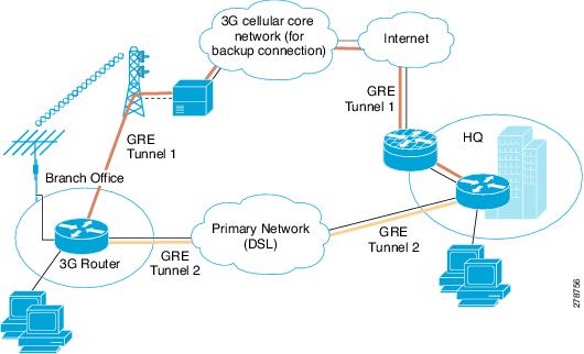
This deployment uses the DSL interface as a primary link and the cellular interface as a backup link, using GRE tunnels and IPsec at a branch office, for secure communication between the hosts on the branch office router and the hosts at the HQ site via public networks. This deployment also allows non-secure (non-IPsec) communication with the hosts on the Internet. For more information on the IPSec configuration over GRE tunnel with dynamic routing, see Configuring a GRE Tunnel over IPsec with OSPF.
Figure 5-2 Primary/Backup Deployment Using GRE Tunnels and IPsec
Configuration for the Branch Office Router
Example 5-3 Configuration for the Branch Office Router
The blue italicized text throughout this configuration is used to indicate comments and will not be seen when a normal console output is viewed. The bold text is used to indicate important commands to refer back to in case of an error. When debugging, ensure that all the commands in bold are the same in your console output.
Unless otherwise noted, the bold text refers to commands associated with the basic cellular configuration. The bold text is also used for other configurations such as the crypto IPsec configuration, the backup configuration, the IP SLA configuration, and the mobile IP configuration. Commands associated with each of these configurations are called out throughout the example for ease of reference when debugging.
The following configuration uses IP SLA, with reliable object tracking. This configuration is optional.
!
hostname branch-router
!
ip cef
!
ip dhcp excluded-address 10.4.0.254
!
! This address is used as a default gateway address for connected host
! on VLAN 104 - Fast Ethernet ports 0/1/0 thru 0/3/0.
!
ip dhcp pool gsmpool
network 10.4.0.0 255.255.0.0
dns-server 66.209.10.201 66.102.163.231
default-router 10.4.0.254
!
! DHCP pool for the hosts connected to the VLAN 104 - Fast Ethernet ports 0/1/0
! thru 0/3/0
!
!
chat-script gsmscript "" "atdt*98*1#" TIMEOUT 30 "CONNECT"
!
! Chat script to dial out via cellular interface
!
!
username cisco privilege 15 secret 5 $1$ccw8$TFmKUmI4QVZhOMuxzq/SH/
!
track 234 rtr 1 reachability
!
! Configures tracked object number 234 to track for reachability using operation 1.
! The object is 'UP' if reachability condition is met.
!
! This is used for the purposes of sending ping packets via the ATM DSL interface (used
! as a primary link) and monitoring the response to help determine if switchover (to
! cellular) is necessary in the event of no response.
!
crypto isakmp policy 1
encr 3des
authentication pre-share
!
! Defines the IKE policy (with priority 1), specifies 3DES during IKE negotiation and
! authentication as pre-shared, using pre-defined keys. The values for lifetime (set to
! 86,400 sec - one day), group (set to 768 bit Diffie-Hellman), and Hash (set to SHA-1)
! are set to their default values.
!
crypto isakmp key mykey address 20.20.241.234
!
! Defines the key (mykey) and the IP address of the gateway (IPsec peer) with which the
! Security Association will be set.
!
crypto ipsec transform-set mytransformset ah-sha-hmac esp-3des
!
! Defines the transform set (mytransformset), which is an acceptable combination of
! security protocols, algorithms, and other settings to apply to IPsec-protected
! traffic.
!
crypto map mytunnelcrypto 10 ipsec-isakmp
set peer 20.20.241.234
set transform-set mytransformset
match address gre-traffic
!
! Defines the crypto map mytunnelcrypto
!
! crypto map specifies the traffic to be protected (using match address <access-list>
! command), the peer end-point to be used, and the transform set to use (mytransformset,
! defined earlier).
!
!
interface Tunnel1
ip unnumbered Dialer2
ip mtu 1400
tunnel source Dialer2
tunnel destination 20.20.241.234
!
! GRE tunnel for traffic to destination 10.10.0.0 network. Tunnel associated with the
! ATM DSL (primary) interface. This tunnel is normally 'UP'. The remote tunnel end-point
! (20.20.241.234) is on the remote VPN Gateway. The local tunnel end-point is the
! address obtained by the ATM DSL link.
!
interface Tunnel2
ip unnumbered Cellular0/3/0
ip mtu 1400
tunnel source Cellular0/3/0
tunnel destination 20.20.241.234
!
! GRE tunnel for traffic to destination 10.10.0.0 network. Tunnel associated with the
! Cellular (secondary) interface. This tunnel is normally 'Down'. The remote tunnel
! end-point (20.20.241.234) is on the remote VPN Gateway. The local tunnel end-point is
! the address obtained by the Cellular link. This tunnel comes 'UP' when a switchover
! occurs to the Cellular interface.
!
interface Loopback1
ip address 1.1.1.1 255.255.255.255
!
interface GigabitEthernet0/0
no ip address
shutdown
!
interface GigabitEthernet0/1
no ip address
shutdown
!
interface FastEthernet0/1/0
switchport access vlan 104
!
interface FastEthernet0/1/1
switchport access vlan 104
!
interface FastEthernet0/1/2
switchport access vlan 104
!
interface FastEthernet0/1/3
switchport access vlan 104
!
! Fast Ethernet ports used by DHCP Client hosts
!
interface ATM0/0/0
no ip address
ip virtual-reassembly
load-interval 30
no atm ilmi-keepalive
dsl operating-mode auto
!
! ATM (DSL) physical interface used as primary interface
!
interface ATM0/0/0.1 point-to-point
ip nat outside
ip virtual-reassembly
no snmp trap link-status
pvc 0/35
pppoe-client dial-pool-number 2
!
!
! ATM sub-interface to be used for the PVC, as a Primary connection. NAT (outside) will
! be used on this interface.
!
! pppoe-client dial-pool-number 2 configures PPP over Ethernet (PPOE) client, specifying
! the dialer pool 2 to be used. This interface is associated with 'interface Dialer 2',
! defined below.
!
interface Cellular0/3/0
ip address negotiated
ip nat outside
encapsulation ppp
dialer in-band
dialer idle-timeout 0
dialer string gsmscript
dialer-group 1
async mode interactive
ppp chap hostname crlaswlech@wwan.ccs
ppp chap password 0 frludi3gIa
ppp ipcp dns request
crypto map mytunnelcrypto
!
! Applies crypto map mytunnelcrypto, defined above, on this backup interface.
!
! dialer-group 1, defines group number 1, which is associated with 'dialer-list 1 ...'
! command, specified below, in this configuration. It defines the 'interesting traffic'
! that triggers the dial out, and places the interface online after establishing the
! PPP. Note that this interface normally remains in a standby state, hence the
! interesting traffic does not trigger a dial out; rather the traffic already flows
! through the primary (ATM DSL) interface.
!
! Defines the interface for NAT, outside.
!
!
interface Vlan104
description used as default gateway address for DHCP clients
ip address 10.4.0.254 255.255.0.0
ip nat inside
!
! Defines VLAN 104 for the hosts connected on the Fast Ethernet ports 0/1/0 thru 0/1/3,
! using NAT (inside interface).
! NAT/PAT will be used for traffic that is not intended to go via the tunnel(s), to the
! 20.20.0.0 network on the peer gateway.
!
interface Dialer2
ip address negotiated
ip nat outside
encapsulation ppp
load-interval 30
dialer pool 2
dialer-group 2
ppp authentication chap callin
ppp chap hostname cisco@cisco.com
ppp chap password 0 cisco123
ppp pap sent-username cisco@cisco.com password 0 cisco123
ppp ipcp dns request
crypto map mytunnelcrypto
!
! dialer pool 2 command associates this dialer interface with the ATM sub-interface
! atm0/0/0.1. 'dialer-group 2' defines group number 2, which is associated with
! 'dialer-list 2 ...' command, specified below, in this configuration. It defines the
! 'interesting traffic' that triggers the dial out, and places the interface online
! after establishing the PPP.
!
! Defines the interface as for NAT, outside.
!
! Applies crypto map mytunnelcrypto, defined above, on this primary interface
!
ip local policy route-map track-primary-if
!
! Specifies the ip route policy as defined by the route map
! 'track-primary-if'
!
ip route 0.0.0.0 0.0.0.0 Dialer2 track 234
!
! Defines the default route via Dialer 2 (ATM DSL), specifying the tracking object
! (234), defined above.
!
! The route will only be installed if the tracked object (234) is 'UP'.
!
ip route 0.0.0.0 0.0.0.0 Cellular0/3/0 254
!
! Defines the default route via the cellular interface, with an administrative distance
! of 254 (higher than the Dialer 2 interface). This is because this interface is
! normally supposed to be a backup interface.
!
ip route 10.10.0.0 255.255.0.0 Tunnel1
!
! Route to the remote 10.10.0.0 VPN network is via the GRE tunnel associated with ATM
! DSL (primary) interface.
!
ip route 10.10.0.0 255.255.0.0 Tunnel2 254
!
! Route to the remote 10.10.0.0 VPN network is via the GRE tunnel associated with
! Cellular (secondary) interface. The administrative distance set to 254 (higher than
! for the Tunnel1).
!
ip nat inside source route-map nat2cell interface Cellular0/3/0 overload
!
! Defines route-map nat2cell (as defined below), as a criteria for the outside NAT
! traffic, via the cellular interface. The 'overload' option causes PAT to be used.
!
! This command is used if the criteria as defined by route-map nat2cell is satisfied.
!
ip nat inside source route-map nat2dsl interface Dialer2 overload
!
! Similarly, as above, defines route-map nat2cell (as defined below), for the outside
! NAT traffic via the Dialer 2 interface (ATM DSL). The 'overload' option causes PAT to
! be used.
!
! This command is used if the criteria as defined by route-map nat2dsl is satisfied.
!
ip access-list extended gre-traffic
permit gre host 75.40.113.246 host 20.20.241.234
permit gre host 166.138.186.119 host 20.20.241.234
!
! gre-traffic access-list for the protection of IPSec traffic through the GRE tunnels
!
! It only protects the GRE-tunneled traffic through the DSL/Cellular interface
! (whichever is the active interface) and the IPsec peer (20.20.241.234) on the remote
! gateway.
!
ip sla 1
icmp-echo 209.131.36.158 source-interface Dialer2
timeout 1000
frequency 2
!
ip sla schedule 1 life forever start-time now
!
! Defines the SLA (service level agreement) for sending pings to IP address
! 209.131.36.158, using the Dialer 2 (ATM DSL) as the source interface, at every 2
! second interval (frequency 2), and wait for 1000 ms (timeout 1000) for a response to
! the ping.
!
! Start the defined SLA now and run this for ever.
!
access-list 1 permit any
!
! Associated with 'dialer-list 1 protocol ip list 1' command below
!
access-list 101 permit ip 10.4.0.0 0.0.255.255 any
!
! Specifies the traffic to match (matches source address for network 10.4.0.0), in order
! to determine the appropriate outgoing interface for non-tunneled traffic, as defined
! under route maps nat2dsl and nat2cell.
!
access-list 102 permit icmp any host 209.131.36.158
!
! Specifies the traffic for route map 'track-primary-interface', so that the ICMP pings
! are only sent through the ATM DSL interface when this interface is active.
!
! This specific address is the one that is pinged through the ATM DSL interface (primary
! link) on a periodic basis, so that network failures, other than at link/PPP level,
! can also be detected and a switchover may still take place to the cellular (secondary)
! interface.
!
! Ensure that the address that is pinged is reliable and will respond to the ping.
!
dialer-list 1 protocol ip list 1
!
! Specifies 'interesting traffic' that will cause the cellular interface to dial out. It
! further specifies access-list 1 (as part of this command, which is defined above)
!
dialer-list 2 protocol ip permit
!
! Specifies 'interesting traffic' that will cause the ATM DSL interface (as part of
! Dialer 2 interface) to dial out.
!
!
route-map track-primary-if permit 10
match ip address 102
set interface Dialer2 null0
!
! Specifies the route-map to be used as a policy criteria, for local routing purpose
! (see the associated command'ip local policy route-map track-primary-if', above).
!
! If this is a ping packet for destination 209.131.36.158 and if the interface Dialer
! 2 (ATM DSL) is 'UP' and connected, send the ping packet. This ping packet is only sent
! via the ATM DSL interface, and not via the cellular interface. The rationale is to
! periodically monitor connectivity (reachability) via the ATM DSL interface, so as to
! perform the switchover when connectivity fails.
!
route-map nat2dsl permit 10
match ip address 101
match interface Dialer2
!
! Specifies this route map to be used, if it meets the match criteria as defined by
! access-list 101 above and if the Dialer 2 interface is 'UP' and connected.
!
! If the source of traffic is from 10.4.0.0 network and if the interface Dialer 2 is
! 'UP' and connected to DSL network, this route map is used by 'ip nat inside source
! nat2dsl ...' command.
!
route-map nat2cell permit 10
match ip address 101
match interface Cellular0/3/0
!
! Specifies this route map to be used if it meets the match criteria as defined by
! access-list 101 above and if the Cellular interface is 'UP' and connected.
!
! If the source of traffic is from 10.4.0.0 network and if
! the interface cellular is 'UP' and connected to the cellular network, this route map
! is used by 'ip nat inside source nat2cell ...'
!
! Clears the NAT entries from the primary/backup interface upon switchover.
!
event manager applet pri_back
event track 234 state any
action 2.0 cli command "clear ip nat trans forced"
!
control-plane
!
line con 0
exec-timeout 0 0
exec prompt timestamp
stopbits 1
line aux 0
stopbits 1
line 0/3/0
exec-timeout 0 0
script dialer gsmscript
login
modem InOut
no exec
transport input all
transport output all
rxspeed 236800
txspeed 118000
line vty 0 4
privilege level 15
login local
transport input telnet
line vty 5 15
privilege level 15
login local
transport input telnet
!
scheduler allocate 20000 1000
!
End
Configuration for the HQ Site Router
Example 5-4 Configuration for the HQ Site Router
The blue italicized text throughout this configuration is used to indicate comments and will not be seen when a normal console output is viewed. The bold text is used to indicate important commands to refer back to in case of an error. When debugging, ensure that all the commands in bold are the same in your console output.
The bold text is used to call out the basic cellular configuration, the crypto IPsec configuration, the IP SLA backup configuration, and the mobile IP configuration. The comments below each of the commands associated with each of these configurations are called out throughout the example for ease of reference when debugging.
!
hostname gateway-router
!
ip cef
!
ip dhcp excluded-address 20.20.248.254
ip dhcp excluded-address 20.20.248.253
ip dhcp excluded-address 20.20.248.225
ip dhcp excluded-address 10.10.0.254
ip dhcp excluded-address 10.10.0.1
!
! DHCP excluded addresses
!
ip dhcp pool 20
network 20.20.248.224 255.255.255.224
dns-server 20.20.248.254
default-router 20.20.248.254
!
! DHCP pool for hosts on the 20.20 network
!
ip dhcp pool 10
network 10.10.0.0 255.255.0.0
default-router 10.10.0.254
!
! DHCP pool for VPN hosts on the 10.10.0.0 network
!
!
username cisco privilege 15 secret 5 $1$QF4K$Z1rE.mwS69FVx1e5l9DCU1
!
crypto isakmp policy 1
encr 3des
authentication pre-share
crypto isakmp key mykey address 0.0.0.0 0.0.0.0
!
crypto ipsec transform-set mytset ah-sha-hmac esp-3des
!
crypto dynamic-map gre_tunnel2 10
description IPsec tunnel to DSL at remote
set transform-set mytset
match address gre-tunnel2
!
crypto dynamic-map gre_tunnel21 10
description IPsec tunnel to Cellular at remote
set transform-set mytset
match address gre-tunnel21
!
crypto map mytunnelcrypto 10 ipsec-isakmp dynamic gre_tunnel2
crypto map mytunnelcrypto 20 ipsec-isakmp dynamic gre_tunnel21
!
!
! Defines the mytunnelcrypto map for tunnels to the ATM DSL interface (Tunnel2) and
! Cellular interface (Tunnel21) at the remote branch-router.
!
!
interface Tunnel2
description tunnel to remote DSL link 75.40.113.246
ip unnumbered Vlan20
tunnel source GigabitEthernet0/0
tunnel destination 75.40.113.246
!
! Tunnel to the ATM DSL interface on the remote branch-router. Normally this is the
! 'active tunnel'.
!
interface Tunnel21
description tunnel to remote Cellular link 166.138.186.119
ip unnumbered Vlan20
tunnel source GigabitEthernet0/0
tunnel destination 166.138.186.119
!
! Tunnel to the Cellular interface on the remote branch-router. Normally this tunnel is
! not active unless connectivity via the DSL interface at the remote end goes down.
!
interface GigabitEthernet0/0
description connected to cisco network, next hop:20.20.241.233
ip address 20.20.241.234 255.255.255.252
load-interval 30
duplex auto
speed auto
media-type rj45
negotiation auto
crypto map mytunnelcrypto
!
! Physical interface on which the crypto map is applied. The interface through which
! the above tunnels are established.
!
interface GigabitEthernet0/1
no ip address
shutdown
!
interface FastEthernet0/1/0
switchport access vlan 10
spanning-tree portfast
!
!
! Fast Ethernet ports on which the VPN hosts (on the 10.10.0.0 network) are connected.
!
interface FastEthernet0/1/8
switchport stacking-partner interface FastEthernet0/3/8
!
interface FastEthernet0/3/0
switchport access vlan 20
spanning-tree portfast
!
!
! Fast Ethernet ports on which other hosts (on the 20.20 network) are connected.
!
interface FastEthernet0/3/8
switchport mode trunk
switchport stacking-partner interface FastEthernet0/1/8
!
interface Vlan10
description private networking vlan
ip address 10.10.0.254 255.255.0.0
vlan-range dot1q 1 4095
exit-vlan-config
!
!
! VLAN for the VPN hosts (on the 10.10.0.0 network)
!
interface Vlan20
description network:20.20.248.224/27
ip address 20.20.248.254 255.255.255.224
no ip route-cahe cef
vlan-range dot1q 1 4095
exit-vlan-config
!
!
! "VLAN for the other hosts (on the 20.20 network)
!
ip route 0.0.0.0 0.0.0.0 20.20.241.233
!
! Default route
!
ip route 10.4.0.0 255.255.0.0 Tunnel2
!
! The route to the remote VPN (10.4.0.0 network) on the branch-router, via the tunnel
! that has the remote end-point on the DSL interface.
!
ip route 10.4.0.0 255.255.0.0 Tunnel21 254
!
! The route to the remote VPN (10.4.0.0 network) on the branch-router, via the tunnel
! that has the remote end-point on the Cellular interface. This route has a higher
! administrative distance.
!
ip access-list extended gre-tunnel2
permit gre host 20.20.241.234 host 75.40.113.246
!
! Access list defining the traffic that will be protected via IPsec. This is the traffic
! sent to the DSL interface at the remote end.
!
ip access-list extended gre-tunnel21
permit gre host 20.20.241.234 host 166.138.186.119
!
! Access list defining the traffic that will be protected via IPsec. This is the traffic
! sent to the Cellular interface at the remote end.
!
control-plane
!
line con 0
exec-timeout 0 0
login local
stopbits 1
line aux 0
stopbits 1
line vty 0 4
privilege level 15
login local
transport input telnet
line vty 5 15
privilege level 15
login local
transport input telnet
!
scheduler allocate 20000 1000
!
end
Primary/Backup Deployment using GRE Tunnels, IPSec, and OSPF Routing
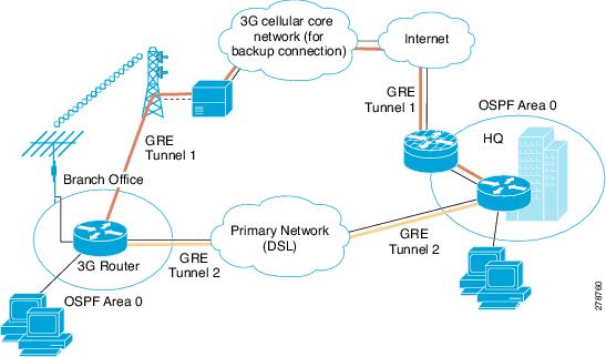
This deployment uses the DSL interface as a primary link and the cellular interface as a backup link, using GRE tunnels and IPsec at a branch office for secure communication between the hosts on the branch office router and the hosts at the HQ site via public networks. It also uses OSPF on the VPN networks (10.4.0.0 and 10.10.0.0 networks) to enable OSPF-assisted routing. This deployment allows non-secure (non-IPsec) communication with the hosts on the Internet. For more information, see Configuring a GRE Tunnel over IPsec with OSPF.
Figure 5-3 Primary/Backup Deployment Using GRE Tunnels, IPsec, and OSPF Routing
Configuration for the Branch Office Router
The blue italicized text throughout this configuration is used to indicate comments and will not be seen when a normal console output is viewed. The bold text is used to indicate important commands to refer back to in case of an error. When debugging, ensure that all the commands in bold are the same in your console output.
The bold text is used to call out the basic cellular configuration, the crypto IPsec configuration, the IP SLA backup configuration, and the mobile IP configuration. The comments below each of the commands associated with each of these configurations are called out throughout the example for ease of reference when debugging.
The following configuration uses IP SLA, using reliable object tracking. This configuration is optional.
Example 5-5 Configuration for the Branch Office Router
!
hostname branch-router
!
ip cef
!
no ip dhcp use vrf connected
ip dhcp excluded-address 10.4.0.254
!
! This address is used as a default gateway address for connected host
! on VLAN 104 - Fast Ethernet ports 0/1/0 thru 0/3/0.
!
ip dhcp pool gsmpool
network 10.4.0.0 255.255.0.0
dns-server 66.209.10.201 66.102.163.231
default-router 10.4.0.254
!
! DHCP pool for the hosts connected to the VLAN 104 - Fast Ethernet ports 0/1/0
! thru 0/3/0
!
!
chat-script gsmscript "" "atdt*98*1#" TIMEOUT 30 "CONNECT"
!
! Chat script to dial out via cellular interface
!
!
username cisco privilege 15 secret 5 $1$ccw8$TFmKUmI4QVZhOMuxzq/SH/
!
track 234 rtr 1 reachability
!
! Configures tracked object number 234 to track for reachability using operation 1.
! The object is 'UP' if reachability condition is met.
!
! This is used for the purposes of sending ping packets via the ATM DSL interface (used
! as a primary link) and monitoring the response to help determine if switchover (to
! cellular) is necessary in the event of no response.
!
crypto isakmp policy 1
encr 3des
authentication pre-share
!
! Defines the IKE policy (with priority 1), specifies 3DES during IKE negotiation and
! authentication as pre-shared, using pre-defined keys. The values for lifetime (set to
! 86,400 sec - one day), group (set to 768 bit Diffie-Hellman), and Hash (set to SHA-1)
! are set to their default values.
!
crypto isakmp key mykey address 20.20.241.234
!
! Defines the key (mykey) and the IP address of the gateway
! (IPsec peer) with which the Security Association will be set.
!
!
crypto ipsec transform-set mytransformset ah-sha-hmac esp-3des
!
! Defines the transform set (mytransformset), which is an acceptable combination of
! security protocols, algorithms, and other settings to apply to IPsec-protected
! traffic.
!
crypto map mytunnelcrypto 10 ipsec-isakmp
set peer 20.20.241.234
set transform-set mytransformset
match address gre-traffic
!
! Defines the crypto map mytunnelcrypto
!
! crypto map specifies the traffic to be protected (using match address <access-list>
! command), the peer end-point to be used, and the transform set to use (mytransformset,
! defined earlier).
!
!
interface Tunnel1
ip unnumbered Vlan104
ip mtu 1400
tunnel source Dialer2
tunnel destination 20.20.241.234
!
! GRE tunnel for traffic to destination 10.10.0.0 network. Tunnel associated with the
! ATM DSL (primary) interface. This tunnel is normally 'UP'. The remote tunnel end-point
! (20.20.241.234) is on the remote VPN Gateway. The local tunnel end-point is the
! address obtained by the ATM DSL link.
!
interface Tunnel2
ip ospf demand-circuit
ip unnumbered Vlan104
ip mtu 1400
tunnel source Cellular0/3/0
tunnel destination 20.20.241.234
!
! 'ip ospf demand-circuit', optional command, suppresses OSPF Hello packets. It helps
! keep the cellular radio level connectivity from unnecessarily going to 'active' state
! (from a 'dormant' state) periodically.
!
! GRE tunnel for traffic to destination 10.10.0.0 network. Tunnel associated with the
! Cellular (secondary) interface. This tunnel is normally 'Down'. The remote tunnel
! end-point (20.20.241.234) is on the remote VPN Gateway. The local tunnel end-point is
! the address obtained by the Cellular link. This tunnel comes 'UP' when a switchover
! occurs to the Cellular interface.
!
interface Loopback1
ip address 1.1.1.1 255.255.255.255
!
interface GigabitEthernet0/0
no ip address
shutdown
!
interface GigabitEthernet0/1
no ip address
shutdown
!
interface FastEthernet0/1/0
switchport access vlan 104
!
interface FastEthernet0/1/1
switchport access vlan 104
!
interface FastEthernet0/1/2
switchport access vlan 104
!
interface FastEthernet0/1/3
switchport access vlan 104
!
! Fast Ethernet ports used by DHCP Client hosts
!
interface ATM0/0/0
no ip address
ip virtual-reassembly
load-interval 30
no atm ilmi-keepalive
dsl operating-mode auto
!
! ATM (DSL) physical interface used as primary interface
!
interface ATM0/0/0.1 point-to-point
ip nat outside
ip virtual-reassembly
no snmp trap link-status
pvc 0/35
pppoe-client dial-pool-number 2
!
!
! ATM sub-interface to be used for the PVC, as a Primary connection. NAT (outside) will
! be used on this interface.
!
! 'pppoe-client dial-pool-number 2' configures PPP over Ethernet (PPOE) client,
! specifying the dialer pool 2 to be used. This interface is associated with 'interface
! Dialer 2', defined below.
!
interface Cellular0/3/0
ip address negotiated
ip nat outside
ip virtual-reassembly
encapsulation ppp
ip ospf demand-circuit
dialer in-band
dialer idle-timeout 0
dialer string gsmscript
dialer-group 1
async mode interactive
ppp chap hostname crlaswlech@wwan.ccs
ppp chap password 0 frludi3gIa
ppp ipcp dns request
crypto map mytunnelcrypto
!
! 'ip ospf demand-circuit' optional command suppresses OSPF Hello packets. It helps keep
! the cellular radio level connectivity from unnecessarily going to 'active' state (from
! a 'dormant' state) periodically.
!
! Applies crypto map mytunnelcrypto, defined above, on this backup interface.
!
! 'dialer-group 1', defines group number 1, which is associated with 'dialer-list 1 ...'
! command, specified below, in this configuration. It defines the 'interesting traffic'
! that triggers the dial out, and places the interface online after establishing the
! PPP. Note that this interface normally remains in a standby state, hence the
! interesting traffic does not trigger a dial out; rather the traffic already flows
! through the primary (ATM DSL) interface.
!
! Defines the interface for NAT, outside.
!
!
interface Vlan104
description used as default gateway address for DHCP clients
ip address 10.4.0.254 255.255.0.0
ip nat inside
ip virtual-reassembly
!
! Defines VLAN 104 for the hosts connected on the Fast Ethernet ports 0/1/0 thru 0/1/3,
! using NAT (inside interface).
!
! NAT/PAT will be used for traffic that is not intended to go via the tunnel(s), to the
! 20.20.0.0 network on the peer gateway.
!
interface Dialer2
ip address negotiated
ip nat outside
encapsulation ppp
load-interval 30
dialer pool 2
dialer-group 2
ppp authentication chap callin
ppp chap hostname cisco@cisco.com
ppp chap password 0 cisco123
ppp pap sent-username cisco@cisco.com password 0 cisco123
ppp ipcp dns request
crypto map mytunnelcrypto
!
! 'dialer pool 2' command associates this dialer interface with the ATM sub-interface
! atm0/0/0.1. 'dialer-group 2' defines group number 2, which is associated with
! 'dialer-list 2 ...' command, specified below, in this configuration. It defines the
! 'interesting traffic' that triggers the dial out and places the interface online
! after establishing the PPP.
!
! Defines the interface as for NAT, outside.
!
! Applies crypto map mytunnelcrypto, defined above, on this primary interface.
!
router ospf 11
log-adjacency-changes
network 10.4.0.0 0.0.0.255 area 0
!
! VPN network 10.4.0.0 (of which Tunnel1/Tunnel2 are part) is part of OSPF area 0.
!
! OSP Hello will be sent across to branch-router via these tunnels.
!
ip local policy route-map track-primary-if
!
! Specifies the ip route policy as defined by the route map 'track-primary-if'.
!
ip route 0.0.0.0 0.0.0.0 Dialer2 track 234
!
! Defines the default route via Dialer 2 (ATM DSL), specifying the tracking object
! (234), defined above.
!
! The route will only be installed if the tracked object (234) is 'UP'.
!
ip route 0.0.0.0 0.0.0.0 Cellular0/3/0 254
!
! Defines the default route via the cellular interface, with an administrative distance
! of 254 (higher than the Dialer 2 interface). This is because this interface is
! normally supposed to be a backup interface.
!
ip http server
ip http authentication local
no ip http secure-server
ip http timeout-policy idle 5 life 86400 requests 10000
ip nat inside source route-map nat2cell interface Cellular0/3/0 overload
!
! Defines route-map nat2cell (as defined below), as a criteria for the outside NAT
! traffic, via the cellular interface. The 'overload' option causes PAT to be used.
!
! This command is used if the criteria as defined by route-map nat2cell is satisfied.
!
ip nat inside source route-map nat2dsl interface Dialer2 overload
!
! Similarly, as above, defines route-map nat2cell (as defined below), for the outside
! NAT traffic via the Dialer 2 interface (ATM DSL). The 'overload' option causes PAT to
! be used.
!
! This command is used if the criteria as defined by route-map nat2dsl is satisfied.
!
ip access-list extended gre-traffic
permit gre host 75.40.113.246 host 20.20.241.234
permit gre host 166.138.186.119 host 20.20.241.234
!
! 'gre-traffic' access-list for the protection of IPSec traffic through the GRE tunnels
!
! It only protects the GRE-tunneled traffic through the DSL/Cellular interface
! (whichever is the active interface) and the IPsec peer (20.20.241.234) on the remote
! gateway.
!
ip sla 1
icmp-echo 209.131.36.158 source-interface Dialer2
timeout 1000
frequency 2
ip sla schedule 1 life forever start-time now
!
! Defines the SLA (service level agreement) for sending pings to IP address
! 209.131.36.158, using the Dialer 2 (ATM DSL) as the source interface, at every 2
! second interval (frequency 2), and wait for 1000 ms (timeout 1000) for a response to
! the ping.
!
! Start the defined SLA now and run this for ever.
!
access-list 1 permit any
!
! Associated with 'dialer-list 1 protocol ip list 1' command below
!
access-list 101 permit ip 10.4.0.0 0.0.255.255 any
!
! Specifies the traffic to match (matches source address for network 10.4.0.0), in order
! to determine the appropriate outgoing interface, for non-tunneled traffic, as defined
! under route maps nat2dsl and nat2cell.
!
access-list 102 permit icmp any host 209.131.36.158
!
! Specifies the traffic for route map 'track-primary-interface', so that the ICMP pings
! are only sent through the ATM DSL interface when this interface is active.
!
! This specific address is the one that is pinged through the ATM DSL interface (primary
! link), on a periodic basis, so that network failures, other than at link/PPP level,
! can also be detected and a switchover may still take place to the cellular (secondary)
! interface.
!
! Ensure that the address that is pinged is reliable and will respond to the ping.
!
dialer-list 1 protocol ip list 1
!
! Specifies 'interesting traffic' that will cause the cellular interface to dial out. It
! further specifies access-list 1 (as part of this command, which is defined above).
!
dialer-list 2 protocol ip permit
!
! Specifies 'interesting traffic' that will cause the ATM DSL interface (as part of
! Dialer 2 interface) to dial out.
!
!
route-map track-primary-if permit 10
match ip address 102
set interface Dialer2 null0
!
! Specifies the route-map to be used as a policy criteria, for local routing purpose
! (see the associated command 'ip local policy route-map track-primary-if', above).
!
! If this is a ping packet for destination 209.131.36.158 and if the interface Dialer
! 2 (ATM DSL) is 'UP' and connected, send the ping packet. This ping packet is only sent
! via the ATM DSL interface and not via the cellular interface. The rationale is to
! periodically monitor connectivity (reachability) via the ATM DSL interface, so as to
! perform the switchover when connectivity fails.
!
route-map nat2dsl permit 10
match ip address 101
match interface Dialer2
!
! Specifies this route map to be used, if it meets the match
! criteria as defined by access-list 101 above and if the
! Dialer 2 interface is 'UP' and connected.
!
! If the source of traffic is from 10.4.0.0 network and if
! the interface Dialer 2 is 'UP' and connected to DSL network,
! this route map is used by 'ip nat inside source nat2dsl ...' command.
!
route-map nat2cell permit 10
match ip address 101
match interface Cellular0/3/0
!
! Specifies this route map to be used, if it meets the match
! criteria as defined by access-list 101 above and if the
! Cellular interface is 'UP' and connected.
!
! If the source of traffic is from 10.4.0.0 network and if
! the interface cellular is 'UP' and connected to the cellular network, this route map
! is used by 'ip nat inside source nat2cell ...'
!
! Clears the NAT entries from the primary/backup interface upon switchover.
!
event manager applet pri_back
event track 234 state any
action 2.0 cli command "clear ip nat trans forced"
!
control-plane
!
line con 0
exec-timeout 0 0
exec prompt timestamp
stopbits 1
line aux 0
stopbits 1
line 0/3/0
exec-timeout 0 0
script dialer gsmscript
login
modem InOut
no exec
transport input all
transport output all
rxspeed 236800
txspeed 118000
line vty 0 4
privilege level 15
login local
transport input telnet
line vty 5 15
privilege level 15
login local
transport input telnet
!
scheduler allocate 20000 1000
!
End
Configuration for the HQ Site Router
Example 5-6 Configuration for the HQ Site Router
The blue italicized text throughout this configuration is used to indicate comments and will not be seen when a normal console output is viewed. The bold text is used to indicate important commands to refer back to in case of an error. When debugging, ensure that all the commands in bold are the same in your console output.
The bold text is used to call out the basic cellular configuration, the crypto IPsec configuration, the IP SLA backup configuration, and the mobile IP configuration. The comments below each of the commands associated with each of these configurations are called out throughout the example for ease of reference when debugging.
!
hostname gateway-router
!
ip cef
!
ip dhcp excluded-address 20.20.248.254
ip dhcp excluded-address 10.10.0.254
ip dhcp excluded-address 10.10.0.1
!
! DHCP excluded addresses
!
ip dhcp pool 20
network 20.20.248.224 255.255.255.224
dns-server 20.20.248.254
default-router 20.20.248.254
!
! DHCP pool for hosts on the 20.20 network
!
ip dhcp pool 10
network 10.10.0.0 255.255.0.0
default-router 10.10.0.254
!
! DHCP pool for VPN hosts on the 10.10.0.0 network
!
!
username cisco privilege 15 secret 5 $1$QF4K$Z1rE.mwS69FVx1e5l9DCU1
!
crypto isakmp policy 1
encr 3des
authentication pre-share
crypto isakmp key mykey address 0.0.0.0 0.0.0.0
!
!
crypto ipsec transform-set mytset ah-sha-hmac esp-3des
!
crypto dynamic-map gre_tunnel2 10
description IPsec tunnel to DSL at remote
set transform-set mytset
match address gre-tunnel2
!
crypto dynamic-map gre_tunnel21 10
description IPsec tunnel to Cellular at remote
set transform-set mytset
match address gre-tunnel21
!
crypto map mytunnelcrypto 10 ipsec-isakmp dynamic gre_tunnel2
crypto map mytunnelcrypto 20 ipsec-isakmp dynamic gre_tunnel21
!
! Defines the mytunnelcrypto map for tunnels to the ATM DSL interface (Tunnel2) and
! Cellular interface (Tunnel21) at the remote branch-router.
!
!
interface Tunnel2
description tunnel to remote DSL link 75.40.113.246
ip unnumbered Vlan10
ip mtu 1400
tunnel source GigabitEthernet0/0
tunnel destination 75.40.113.246
!
! Tunnel to the ATM DSL interface on the remote branch-router. Normally this is the
! 'active tunnel'.
!
interface Tunnel21
description tunnel to remote Cellular link 166.138.186.119
ip unnumbered Vlan10
ip mtu 1400
tunnel source GigabitEthernet0/0
tunnel destination 166.138.186.119
!
! Tunnel to the Cellular interface on the remote branch-router. Normally this tunnel is
! not active unless connectivity via the DSL interface at the remote end goes down.
!
interface GigabitEthernet0/0
description connected to cisco network, next hop:20.20.241.233
ip address 20.20.241.234 255.255.255.252
load-interval 30
crypto map mytunnelcrypto
!
! Physical interface on which the crypto map is applied. The interface through which the
! above tunnels are established.
!
interface GigabitEthernet0/1
no ip address
shutdown
!
interface FastEthernet0/1/0
switchport access vlan 10
spanning-tree portfast
!
! Fast Ethernet ports on which the VPN hosts (on the 10.10.0.0 network) are connected.
!
interface FastEthernet0/1/8
switchport stacking-partner interface FastEthernet0/3/8
!
interface FastEthernet0/3/0
switchport access vlan 20
spanning-tree portfast
!
! Fast Ethernet ports on which other hosts (on the 20.20 network) are connected.
!
interface FastEthernet0/3/8
switchport mode trunk
switchport stacking-partner interface FastEthernet0/1/8
!
interface Vlan10
description private networking vlan
ip address 10.10.0.254 255.255.0.0
no ip route-cache cef
vlan-range dot1q 1 4095
exit-vlan-config
!
!
! VLAN for the VPN hosts (on the 10.10.0.0 network).
!
interface Vlan20
description network:20.20.248.224/27
ip address 20.20.248.254 255.255.255.224
no ip route-cahe cef
vlan-range dot1q 1 4095
exit-vlan-config
!
!
! VLAN for the other hosts (on the 20.20 network)
!
router ospf 10
log-adjacency-changes
network 10.10.0.0 0.0.0.255 area 0
!
! VPN network 10.10.0.0 (of which Tunnel2/Tunnel21 are part) is part of OSPF area 0.
!
! OSP Hello will be sent across to branch-router via these tunnels
!
ip route 0.0.0.0 0.0.0.0 20.20.241.233
!
! default route - the next hop for GigabitEthernet0/0 interface.
!
ip dns server
!
ip access-list extended gre-tunnel2
permit gre host 20.20.241.234 host 75.40.113.246
!
! Access list defining the traffic that will be protected via IPsec. This is the traffic
! sent to the DSL interface at the remote end.
!
ip access-list extended gre-tunnel21
permit gre host 20.20.241.234 host 166.138.186.119
!
! Access list defining the traffic that will be protected via IPsec. This is the traffic
! sent to the Cellular interface at the remote end.
!
control-plane
!
line con 0
exec-timeout 0 0
login local
stopbits 1
line aux 0
stopbits 1
line vty 0 4
privilege level 15
login local
transport input telnet
line vty 5 15
privilege level 15
login local
transport input telnet
!
scheduler allocate 20000 1000
!
End
DMVPN Deployment with IPSec and OSPF
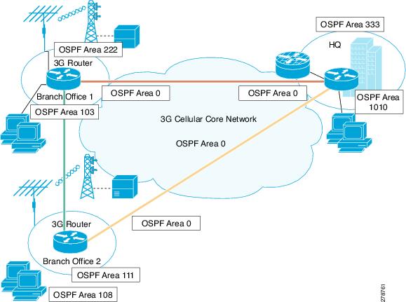
This deployment uses Cellular interface as a primary link, using DMVPN (GRE Tunnels) and IPsec for secure communication between the hosts on the branch office router and the hosts at the HQ site via public networks and OSPF as the routing protocol. For more information on DMVPN, see Dynamic Multipoint VPN (DMVPN).
Figure 5-4 Primary Deployment Using DMVPN with IPSec and OSPF
Configuration for the Branch-1 Office Router
Example 5-7 Configuration for the Branch-1 Office Router
The blue italicized text throughout this configuration is used to indicate comments and will not be seen when a normal console output is viewed. The bold text is used to indicate important commands to refer back to in case of an error. When debugging, ensure that all the commands in bold are the same in your console output.
The bold text is used to call out the basic cellular configuration, the crypto IPsec configuration, the IP SLA backup configuration, and the mobile IP configuration. The comments below each of the commands associated with each of these configurations are called out throughout the example for ease of reference when debugging.
!
hostname DMVPN_Spoke_1
!
Ip cef
!
crypto isakmp policy 10
hash md5
authentication pre-share
!
!
! ISAKMP policy for phase 1 negotiation
!
crypto isakmp key cisco123 address 0.0.0.0 0.0.0.0
!
! Pre-shared key for Hub and remote DMVPN spokes
!
!
crypto ipsec transform-set strong esp-3des esp-md5-hmac
!
! IPsec (Phase 2) policy for actual data encryption/integrity
!
!
crypto ipsec profile cisco
set security-association lifetime seconds 86400
set transform-set strong
!
! IPsec Profile to be applied dynamically to the GRE over IPsec tunnels
!
!
ip dhcp excluded-address 10.3.0.254
!
ip dhcp pool cdmapool
network 10.3.0.0 255.255.0.0
dns-server 68.28.58.11
default-router 10.3.0.254
!
chat-script cdma1 "" "atdt#777" TIMEOUT 180 "CONNECT"
!
username cisco privilege 15 secret 5 $1$c/5O$W4sr3BFW3AhIB9BRXjy84/
!
interface Loopback0
ip address 2.2.2.1 255.255.255.0
!
interface Tunnel0
ip address 192.168.10.3 255.255.255.0
no ip redirects
ip mtu 1440
ip nhrp map multicast dynamic
ip nhrp map multicast 20.20.241.234
ip nhrp map 192.168.10.1 20.20.241.234
ip nhrp network-id 1
ip nhrp nhs 192.168.10.1
ip nhrp registration no-unique
ip nhrp cache non-authoritative
ip ospf network broadcast
tunnel source dialer 1
tunnel mode gre multipoint
tunnel key 0
tunnel protection ipsec profile Cisco
!
! GRE tunnel template which will be applied to all dynamically created GRE tunnels.
!
!
interface GigabitEthernet0/0
no ip address
shut down
!
interface GigabitEthernet0/1
no ip address
shutdown
!
interface FastEthernet0/2/0
switchport access vlan 103
!
interface FastEthernet0/2/1
switchport access vlan 103
!
interface FastEthernet0/2/2
switchport access vlan 103
!
interface FastEthernet0/2/3
switchport access vlan 103
!
!
! Following cellular configuration is for dialer persistent. This will always keep the
! cellular interface up and get an ip address. The dialer pool and dialer pool-member
! commands associate the dialer interface and the cellular interface.
!
!
interface Cellular0/1/0
no ip address
encapsulation ppp
dialer in-band
dialer pool-member 1
!
interface Dialer1
ip address negotiated
ip nat outside
encapsulation ppp
dialer pool 1
dialer string cdma1
dialer persistent
ppp chap hostname isp-provided-hostname
ppp chap password 0 isp-provided-password
ppp ipcp dns request
!
interface Vlan1
no ip address
!
interface Vlan103
ip address 10.3.0.254 255.255.0.0
ip nat inside
ip virtual-reassembly
!
router ospf 90
log-adjacency-changes
network 2.2.2.0 0.0.0.255 area 222
network 10.3.0.0 0.0.255.255 area 103
network 192.168.10.0 0.0.0.255 area 0
!
ip route 20.20.241.234 255.255.255.255 dialer 1
!
!
control-plane
!
line con 0
exec-timeout 0 0
line aux 0
line 0/1/0
exec-timeout 0 0
script dialer cdma1
login
modem InOut
no exec
transport input all
transport output all
rxspeed 3100000
txspeed 1800000
line vty 0 4
privilege level 15
no login
transport input telnet
line vty 5 15
privilege level 15
login local
transport input telnet
!
scheduler allocate 20000 1000
!
webvpn cef
!
end
Configuration for the Branch-2 Office Router
Example 5-8 Configuration for the Branch-2 Office Router
The blue italicized text throughout this configuration is used to indicate comments and will not be seen when a normal console output is viewed. The bold text is used to indicate important commands to refer back to in case of an error. When debugging, ensure that all the commands in bold are the same in your console output.
The bold text is used to call out the basic cellular configuration, the crypto IPsec configuration, the IP SLA backup configuration, and the mobile IP configuration. The comments below each of the commands associated with each of these configurations are called out throughout the example for ease of reference when debugging.
!
hostname DMVPN_Spoke_2
!
!
crypto isakmp policy 10
hash md5
authentication pre-share
!
! ISAKMP policy for phase 1 negotiation
!
!
crypto isakmp key cisco123 address 0.0.0.0 0.0.0.0
!
! Pre-shared key for all the remote DMVPN spokes
!
!
crypto ipsec transform-set strong esp-3des esp-md5-hmac
!
! IPsec (Phase 2) policy for actual data encryption/integrity
!
!
crypto ipsec profile cisco
set security-association lifetime seconds 86400
set transform-set strong
!
! IPsec Profile to be applied dynamically to the GRE over IPsec tunnels
!
!
ip cef
!
ip dhcp excluded-address 10.8.0.1
ip dhcp excluded-address 10.8.0.254
!
ip dhcp pool cdmapool
network 10.8.0.0 255.255.0.0
default-router 10.8.0.254
!
!
chat-script cdma2 "" "atdt#777" TIMEOUT 180 "CONNECT"
!
username cisco privilege 15 secret 5 $1$YNWp$1OLVYb0qkTnZFmkgcCK1L0
!
interface Loopback1
ip address 1.1.1.1 255.255.255.0
!
interface Tunnel0
ip address 192.168.10.2 255.255.255.0
no ip redirects
ip mtu 1440
ip nhrp map multicast dynamic
ip nhrp map multicast 20.20.241.234
ip nhrp map 192.168.10.1 20.20.241.234
ip nhrp network-id 1
ip nhrp nhs 192.168.10.1
ip nhrp registration no-unique
ip nhrp cache non-authoritative
ip ospf network broadcast
tunnel source dialer 1
tunnel mode gre multipoint
tunnel key 0
tunnel protection ipsec profile Cisco
!
! GRE tunnel template which will be applied to all dynamically created GRE tunnels.
!
!
interface FastEthernet0/0
no ip address
shutdown
!
interface FastEthernet0/1
ip address dhcp
shutdown
!
interface FastEthernet0/3/0
switchport access vlan 108
!
interface FastEthernet0/3/1
!
interface FastEthernet0/3/2
switchport access vlan 108
!
interface FastEthernet0/3/3
switchport access vlan 108
!
!
! Following cellular configuration is for dialer persistent. This will always keep the
! cellular interface up and get an ip address. The dialer pool and dialer pool-member
! commands associate the dialer interface and the cellular interface.
!
!
interface Cellular0/1/0
no ip address
encapsulation ppp
dialer in-band
dialer pool-member 1
!
interface Dialer1
ip address negotiated
ip nat outside
encapsulation ppp
dialer pool 1
dialer string cdma2
dialer persistent
ppp chap hostname isp-provided-hostname
ppp chap password 0 isp-provided-password
ppp ipcp dns request
!
interface Vlan108
description used as default gateway address for DHCP clients
ip address 10.8.0.254 255.255.0.0
ip virtual-reassembly
!
router ospf 90
log-adjacency-changes
network 1.1.1.0 0.0.0.255 area 111
network 10.8.0.0 0.0.0.255 area 108
network 192.168.10.0 0.0.0.255 area 0
!
ip route 20.20.241.234 255.255.255.255 dialer 1
!
control-plane
!
line con 0
exec-timeout 0 0
line aux 0
line 0/1/0
exec-timeout 0 0
script dialer cdma2
login
modem InOut
no exec
transport input all
transport output all
autoselect during-login
autoselect ppp
rxspeed 3100000
txspeed 1800000
line vty 0 4
access-class 23 in
privilege level 15
login local
transport input telnet ssh
line vty 5 15
access-class 23 in
privilege level 15
login local
transport input telnet ssh
!
scheduler allocate 20000 1000
!
end
Configuration for the HQ Site Router
Example 5-9 Configuration for the HQ Site Router
The blue italicized text throughout this configuration is used to indicate comments and will not be seen when a normal console output is viewed. The bold text is used to indicate important commands to refer back to in case of an error. When debugging, ensure that all the commands in bold are the same in your console output.
The bold text is used to call out the basic cellular configuration, the crypto IPsec configuration, the IP SLA backup configuration, and the mobile IP configuration. The comments below each of the commands associated with each of these configurations are called out throughout the example for ease of reference when debugging.
!
hostname DMVPN_Hub
!
ip cef
!
ip dhcp pool 20
network 20.20.248.224 255.255.255.224
dns-server 20.20.248.254
default-router 20.20.248.254
!
ip dhcp pool 10
network 10.10.0.0 255.255.0.0
default-router 10.10.0.254
!
ip dhcp pool 192
network 192.168.1.0 255.255.255.0
dns-server 192.168.1.254
default-router 192.168.1.254
!
!
crypto isakmp policy 10
hash md5
authentication pre-share
!
! ISAKMP policy for phase 1 negotiation
!
!
crypto isakmp key cisco123 address 0.0.0.0 0.0.0.0
!
! Pre-shared key for all the remote DMVPN spokes
!
!
crypto ipsec transform-set strong esp-3des esp-md5-hmac
!
! IPsec (Phase 2) policy for actual data encryption/integrity
!
!
crypto ipsec profile cisco
set security-association lifetime seconds 86400
set transform-set strong
!
! IPsec Profile to be applied dynamically to the GRE over IPsec tunnels
!
!
username cisco privilege 15 secret 5 $1$QF4K$Z1rE.mwS69FVx1e5l9DCU1
!
interface Loopback33
ip address 3.3.3.3 255.255.255.0
!
interface Tunnel0
ip address 192.168.10.1 255.255.255.0
no ip redirects
ip mtu 1440
ip nhrp map multicast dynamic
ip nhrp network-id 1
ip nhrp cache non-authoritative
ip ospf network broadcast
tunnel source GigabitEthernet0/0
tunnel mode gre multipoint
tunnel key 0
tunnel protection ipsec profile cisco
!
!
! GRE tunnel template which will be applied to all dynamically created GRE tunnels.
!
interface GigabitEthernet0/0
description connected to cisco network, next hop:20.20.241.233
ip address 20.20.241.234 255.255.255.252
!
interface GigabitEthernet0/1
no ip address
shutdown
!
interface FastEthernet0/1/0
switchport access vlan 10
no cdp enable
spanning-tree portfast
!
!
interface FastEthernet0/1/8
switchport stacking-partner interface FastEthernet0/3/8
no cdp enable
!
interface FastEthernet0/3/0
switchport access vlan 20
no cdp enable
spanning-tree portfast
!
interface FastEthernet0/3/8
switchport mode trunk
switchport stacking-partner interface FastEthernet0/1/8
no cdp enable
!
interface Vlan10
description private networking vlan
ip address 10.10.0.254 255.255.0.0
no ip route-cache cef
!
interface Vlan20
description network:20.20.248.224,mask:/27,last host:20.20.248.254
ip address 20.20.248.254 255.255.255.224
no ip route-cache cef
!
router ospf 90
log-adjacency-changes
network 3.3.3.0 0.0.0.255 area 333
network 10.10.0.0 0.0.255.255 area 1010
network 192.168.10.0 0.0.0.255 area 0
!
ip route 0.0.0.0 0.0.0.0 20.20.241.233
!
control-plane
!
!
line con 0
exec-timeout 0 0
stopbits 1
line aux 0
stopbits 1
line vty 0 4
privilege level 15
transport input telnet
line vty 5 15
privilege level 15
transport input telnet
!
scheduler allocate 20000 1000
!
webvpn cef
!
end
EzVPN Deployment with Primary and Backup Links
EzVPN is specifically designed for ease of deployment and scalability for the HQ-Branch deployment with a large number of branches. This deployment uses the DSL interface as a primary link and the cellular link as the backup link. For more information on EzVPN, see Cisco Easy VPN.
Figure 5-5 EzVPN Deployment Using Primary/Backup
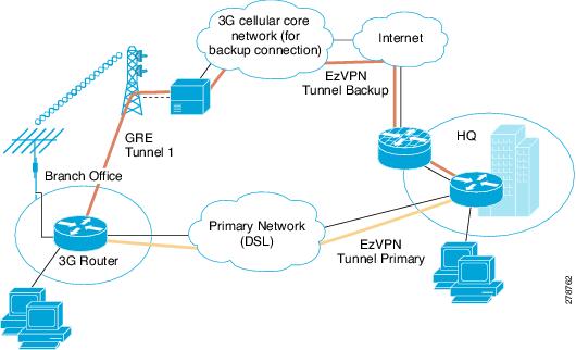
Configuration for the EzVPN client (Branch Router)
Example 5-10 Configuration for the EzVPN client (Branch Router)
The blue italicized text throughout this configuration is used to indicate comments and will not be seen when a normal console output is viewed. The bold text is used to indicate important commands to refer back to in case of an error. When debugging, ensure that all the commands in bold are the same in your console output.
The bold text is used to call out the basic cellular configuration, the crypto IPsec configuration, the IP SLA backup configuration, and the mobile IP configuration. The comments below each of the commands associated with each of these configurations are called out throughout the example for ease of reference when debugging.
!
hostname branch-router
!
ip cef
!
ip dhcp excluded-address 10.13.0.254
!
ip dhcp pool gsmpool
network 10.4.0.0 255.255.0.0
dns-server 66.209.10.201 66.102.163.231
default-router 10.13.0.254
!
chat-script gsmscript "" "atdt*98*1#" TIMEOUT 20 "CONNECT"
!
! Chat script to dial out via cellular interface
!
username cisco123@cisco.com password 0 lab
username cisco password 0 lab
username sachin@cisco.com password 0 lab
!
! Local username and password for authentication for EzVPN client
!
!
track 234 rtr 1 reachability
!
crypto ipsec client ezvpn hw-client-pri
connect auto
group hw-client-group key cisco123
backup hw-client track 234
mode network-extension
peer 128.107.248.243
username cisco123@cisco.com password lab
xauth userid mode local
!
! EzVPN client configuration for Primary WAN interface. Uses track 234 to failover to
! backup when backup WAN is being used
!
!
crypto ipsec client ezvpn hw-client
connect auto
group hw-client-group key cisco123
mode network-extension
peer 128.107.248.243
username sachin@cisco.com password lab
xauth userid mode local
!
! EzVPN client configuration for Backup WAN interface
!
!
interface Loopback1
ip address 1.1.1.1 255.255.255.255
!
interface GigabitEthernet0/0
no ip address
shutdown
!
interface GigabitEthernet0/1
no ip address
shutdown
!
interface FastEthernet0/1/0
switchport access vlan 104
!
interface FastEthernet0/1/1
switchport access vlan 104
!
interface FastEthernet0/1/2
switchport access vlan 104
!
interface FastEthernet0/1/3
switchport access vlan 104
!
! Fast Ethernet ports used by DHCP Client hosts
!
interface ATM0/0/0
no ip address
ip virtual-reassembly
load-interval 30
no atm ilmi-keepalive
dsl operating-mode auto
!
! ATM (DSL) physical interface used as primary interface
!
interface ATM0/0/0.1 point-to-point
ip nat outside
ip virtual-reassembly
no snmp trap link-status
pvc 0/35
pppoe-client dial-pool-number 2
!
interface Cellular0/1/0
no ip address
ip nat outside
encapsulation ppp
dialer in-band
dialer pool-member 1
dialer-group 1
async mode interactive
ppp ipcp dns request
!
interface Vlan104
description ip address used as default gateway address for DHCP clients
ip address 10.13.0.254 255.255.0.0
ip nat inside
ip virtual-reassembly
crypto ipsec client ezvpn hw-client-pri inside
crypto ipsec client ezvpn hw-client inside
!
! Defines VLAN 104 for the hosts connected on the Fast Ethernet ports 0/1/0 thru 0/1/3
! to be part of the internal interface for EzVPN encryption.
!
interface Dialer1
ip address negotiated
ip nat outside
encapsulation ppp
dialer pool 1
dialer string gsmscript
dialer persistent
dialer-group 1
ppp chap hostname cisco@cisco.com
ppp chap password 0 cisco123
ppp ipcp dns request
crypto ipsec client ezvpn hw-client
!
! External dialer interface to associate with the cellular interface
!
! crypto ipsec client ezvpn hw-client defined above, on this backup interface. This
! ensures that this is external interface for EzVPN for encryption
!
interface Dialer2
ip address negotiated
ip nat outside
encapsulation ppp
dialer pool 2
dialer-group 2
ppp chap hostname Cisco@cisco.com
ppp chap password 0 cisco
ppp ipcp dns request
crypto ipsec client ezvpn hw-client-pri inside
!
!
! Defines the outside EzVPN interface for primary WAN
!
ip local policy route-map track-primary-if
!
ip route 0.0.0.0 0.0.0.0 Dialer2 track 234
ip route 0.0.0.0 0.0.0.0 Dialer 1 253
!
access-list 1 permit any
!
access-list 102 permit icmp any host 209.131.36.158
!
dialer-list 1 protocol ip list 1
!
dialer-list 2 protocol ip permit
no cdp run
!
!
!
route-map track-primary-if permit 10
match ip address 102
set interface Dialer2 null0
!
control-plane
!
line con 0
exec-timeout 0 0
exec prompt timestamp
stopbits 1
line aux 0
stopbits 1
line 0/1/0
exec-timeout 0 0
script dialer gsmscript
login
modem InOut
no exec
transport input all
transport output all
rxspeed 236800
txspeed 118000
line vty 0 4
privilege level 15
login local
transport input telnet
line vty 5 15
privilege level 15
login local
transport input telnet
!
scheduler allocate 20000 1000
!
end
Configuration for the EzVPN Server Router
Example 5-11 Configuration for the EzVPN Server Router
The blue italicized text throughout this configuration is used to indicate comments and will not be seen when a normal console output is viewed. The bold text is used to indicate important commands to refer back to in case of an error. When debugging, ensure that all the commands in bold are the same in your console output.
The bold text is used to call out the basic cellular configuration, the crypto IPsec configuration, the IP SLA backup configuration, and the mobile IP configuration. The comments below each of the commands associated with each of these configurations are called out throughout the example for ease of reference when debugging.
hostname ezvpn_gw
!
ip cef
!
username cisco123@cisco.com password 0 lab
username sachin@cisco.com password 0 lab
!
crypto isakmp policy 1
encr 3des
hash md5
authentication pre-share
group 2
lifetime 1800
crypto isakmp client configuration address-pool local dynpool
!
crypto isakmp client configuration group hw-client-group
key cisco123
dns 10.11.0.1
domain cisco.com
pool dynpool
acl 111
!
!
crypto ipsec transform-set set1 esp-3des esp-md5-hmac
!
crypto dynamic-map dynmap 1
set transform-set set1
!
!
crypto map dynmap isakmp authorization list hw-client-groupname
crypto map dynmap client configuration address respond
crypto map dynmap 1 ipsec-isakmp dynamic dynmap
!
!
! EzVPN server side configuration. ACL 111 defines the allowed traffic to be encrypted
! from the EzVPN client and is negotiated during IPSec tunnel setup.
!
!
interface GigabitEthernet0/0
ip address 128.107.248.243 255.255.255.224
ip nat outside
duplex auto
speed auto
crypto map dynmap
!
!
! Crypto map is applied on the WAN interface of the server.
!
!
interface GigabitEthernet0/1
ip address 10.11.0.1 255.255.255.0
ip nat inside
ip virtual-reassembly
duplex auto
speed auto
media-type rj45
no cdp enable
!
ip local pool dynpool 10.11.0.50 10.11.0.100
!
! Defines the local pool to give IP address to the remote EzVPN clients.
!
!
ip nat inside source list 101 interface GigabitEthernet0/0 overload
ip route 0.0.0.0 0.0.0.0 128.107.248.254
!
access-list 111 permit ip 10.11.0.0 0.0.0.255 10.13.0.0 0.0.0.255
!
! Defines interesting traffic that should be allowed to be encrypted for the EzVPN
! remote clients. The counterpart of such acl is communicated to the EzVPN remote client
! for encryption and NAT.
!
!
control-plane
!
!
!
line con 0
exec-timeout 0 0
exec prompt timestamp
line aux 0
line vty 0 4
login
!
end
NEMO Over 3G with CCOA-Only Mode
Network Mobility (NEMO) is a scalable option that can be used to deploy multiple branches as stub networks across wide geographic areas. All the branches act as mobile networks connected behind the branch router and establish all the connectivity by dynamic mobile IP tunnels over the WAN link. The example configuration below shows the mobile IP in collocated care of address only (CCOA-only) mode, where the Foreign Agent (FA) is absent. For more information on NEMO deployment in the branch, see Introduction to Mobile IP.
Figure 5-6 NEMO Deployment Over 3G WAN
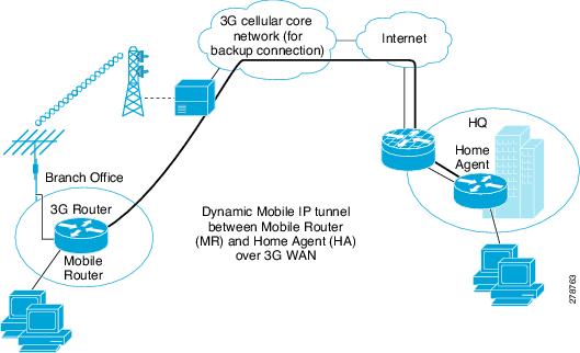
Configuration for the Mobile Router (MR) at the Branch Office
Example 5-12 Configuration for the Mobile Router (MR) at the Branch Office
!
hostname mobile-router
!
ip cef
!
ip dhcp excluded-address 10.13.0.254
!
ip dhcp pool gsmpool
network 10.4.0.0 255.255.0.0
dns-server 66.209.10.201 66.102.163.231
default-router 10.13.0.254
!
chat-script gsmscript "" "atdt*98*1#" TIMEOUT 20 "CONNECT"
!
! Chat script to dial out via cellular interface
!
track 234 rtr 1 reachability
!
! Object tracking for backup method.
!
interface Loopback100
ip address 10.100.0.3 255.255.255.0
!
! Static ip address assigned to the mobile router. This address is part of the HA-MR
! subnet
!
interface GigabitEthernet0/0
no ip address
shutdown
!
interface GigabitEthernet0/1
no ip address
shutdown
!
interface FastEthernet0/1/0
switchport access vlan 104
!
interface FastEthernet0/1/1
switchport access vlan 104
!
interface FastEthernet0/1/2
switchport access vlan 104
!
interface FastEthernet0/1/3
switchport access vlan 104
!
! Fast Ethernet ports used by DHCP Client hosts
!
interface ATM0/0/0
no ip address
ip virtual-reassembly
load-interval 30
no atm ilmi-keepalive
dsl operating-mode auto
!
! ATM (DSL) physical interface used as primary interface
!
interface ATM0/0/0.1 point-to-point
ip nat outside
ip virtual-reassembly
no snmp trap link-status
pvc 0/35
pppoe-client dial-pool-number 2
!
interface Cellular0/1/0
no ip address
ip nat outside
encapsulation ppp
dialer in-band
dialer pool-member 1
dialer-group 1
async mode interactive
ppp ipcp dns request
!
! Using external dialer (dialer 1) for mobile ip deployment, dialer pool-member 1
! associates cellular interface to the dialer 1 where dialar pool 1 is configured.
!
!
interface Vlan104
description ip address used as default gateway address for DHCP clients
ip address 10.13.0.254 255.255.0.0
ip nat inside
ip virtual-reassembly
!
! Defines VLAN 104 for the hosts connected on the Fast Ethernet ports 0/1/0 thru 0/1/3,
! this subnet will be the mobile network behind mobile router.
!
interface Dialer1
ip address negotiated
ip nat outside
ip mobile router-service roam
ip mobile router-service collocated ccoa-only
encapsulation ppp
dialer pool 1
dialer string gsmscript
dialer persistent
dialer-group 1
ppp chap hostname cisco@cisco.com
ppp chap password 0 cisco123
ppp ipcp dns request
!
! External dialer interface associated with the cellular with the mobile
! ip ipconfiguration for ccoa-only mobile ip mode.
!
interface Dialer2
ip address negotiated
ip nat outside
encapsulation ppp
dialer pool 2
dialer-group 2
ppp chap hostname Cisco@cisco.com
ppp chap password 0 cisco
ppp ipcp dns request
!
router mobile
!
! This commands turns on the mobile ip functionality on the router.
!
!
ip local policy route-map track-primary-if
!
ip route 0.0.0.0 0.0.0.0 Dialer2 track 234
ip route 0.0.0.0 0.0.0.0 dialer 0/0/0 253
!
ip mobile secure home-agent 128.107.248.243 spi decimal 1003 key ascii 1234567891234563
algorithm md5 mode prefix-suffix
!
! This statement defines the encryption details and authentication using ascii value.
! The ascii value must match that of the HA configuration on the HQ side router.
!
ip mobile registration-lifetime 1800
ip mobile router
address 10.100.0.3 255.255.255.0
collocated single-tunnel
home-agent 128.107.248.243
mobile-network GigabitEthernet0/1
register retransmit initial 5000 maximum 10000 retry 5
reverse-tunnel
!
! Address defines the Mobile router static ip address defined on the loopback 100.
!
! Home agent address is defined so the router knows who to initiate the mobile ip
! request to.
!
ip sla 1
icmp-echo 209.131.36.158 source-interface Dialer2
timeout 1000
frequency 2
ip sla schedule 1 life forever start-time now
access-list 1 permit any
!
access-list 102 permit icmp any host 209.131.36.158
!
dialer-list 1 protocol ip list 1
!
dialer-list 2 protocol ip permit
no cdp run
!
!
!
route-map track-primary-if permit 10
match ip address 102
set interface Dialer2 null0
!
control-plane
!
bridge 1 protocol ieee
!
line con 0
exec-timeout 0 0
exec prompt timestamp
stopbits 1
line aux 0
stopbits 1
line 0/1/0
exec-timeout 0 0
script dialer gsmscript
login
modem InOut
no exec
transport input all
transport output all
rxspeed 236800
txspeed 118000
line vty 0 4
privilege level 15
login local
transport input telnet
!
scheduler allocate 20000 1000
!
end
Configuration for the Home Agent (HA) Router at HQ
Example 5-13 Configuration for the Home Agent (HA) Router at HQ
The blue italicized text throughout this configuration is used to indicate comments and will not be seen when a normal console output is viewed. The bold text is used to indicate important commands to refer back to in case of an error. When debugging, ensure that all the commands in bold are the same in your console output.
The bold text is used to call out the basic cellular configuration, the crypto IPsec configuration, the IP SLA backup configuration, and the mobile IP configuration. The comments below each of the commands associated with each of these configurations are called out throughout the example for ease of reference when debugging.
hostname HQ-HomeAgent
!
ip cef
!
interface Loopback100
ip address 10.100.0.1 255.255.255.0
!
! Mobile IP Subnet between the Home-agent (HA) and Mobile router (MR)
!
interface GigabitEthernet0/0
ip address 128.107.248.243 255.255.255.224
ip nat outside
duplex auto
speed auto
!
! This is the WAN interface connecting to Mobile routers over internet
!
interface GigabitEthernet0/1
ip address 10.11.0.1 255.255.255.0
ip nat inside
ip virtual-reassembly
duplex auto
speed auto
media-type rj45
no cdp enable
!
router mobile
!
! Enables mobile ip on HA router
!
!
ip nat inside source list 101 interface GigabitEthernet0/0 overload
!
ip route 0.0.0.0 0.0.0.0 128.107.248.254
!
ip mobile home-agent reverse-tunnel private-address
ip mobile home-agent QoS policer
ip mobile home-agent address 128.107.248.243 lifetime 1800 replay 255 unknown-ha accept
reply
!
! Home agent configuration
!
ip mobile host 10.100.0.3 virtual-network 10.100.0.0 255.255.255.0
ip mobile mobile-networks 10.100.0.3
register
!
! Mobile router entry for registration
!
ip mobile secure host 10.100.0.3 spi decimal 1003 key ascii 1234567891234563 algorithm md5
mode prefix-suffix
ip mobile registration-lifetime 1800
!
! Mobile router authentication (same ascii configured as that on the MR) and encryption
! details for secure communication
!
access-list 101 permit ip 13.1.1.0 0.0.0.255 any
!
control-plane
!
line con 0
exec-timeout 0 0
exec prompt timestamp
line aux 0
line vty 0 4
login
!
end
3G L2TP VPN Deployments
Layer 2 Tunneling Protocol (L2TP) is an extension to the PPP protocol used for Virtual Private Networks (VPN). It merges the best features of two existing tunneling protocols: Cisco's Layer 2 Forwarding (L2F) and Microsoft's Point-to-Point Tunneling Protocol (PPTP). L2TP tunnel is established between the L2TP Access Concentrator (LAC) and the L2TP Network Server (LNS). For more information on L2TP, see the Layer 2 Tunneling Protocol Feature Guide.
Figure 5-7 shows an L2TP deployment where LAC acts as either GGSN or PDSN and LNS acts as the server in the service provider premises. L2TP deployments are dynamic such that when a call is initiated, the L2TP tunnel establishes a connection from the LAC to the LNS, followed by PPP LCP, PPP authentication, and PPP IPCP between the LAC to LNS. During the PPP authentication phase, the 3G mode user credential is authenticated with LNS. These user credentials will be configured in the modem or SIM card.
Figure 5-7 L2TP Deployment
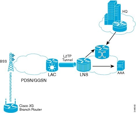
Example 5-14 Show Run Configuration
The blue italicized text throughout this configuration is used to indicate comments and will not be seen when a normal console output is viewed. The bold text is used to indicate important commands to refer back to in case of an error. When debugging, ensure that all the commands in bold are the same in your console output.
Configuration:
Building configuration...
Current configuration : 1816 bytes
!
no service pad
service timestamps debug datetimemsec
service timestamps log datetimemsec
no service password-encryption
service internal
!
hostname Router
!
boot-start-marker
boot-end-marker
!
logging message-counter syslog
enable secret 5 $1$gPgv$3s1bU4gkpa5o/b68Mj8gS0
!
noaaa new-model
memory-sizeiomem 10
!
!
ip source-route
!
ipcef
noipv6cef
!
multilink bundle-name authenticated
chat-script bank "" "ATDT#777" TIMEOUT 60 "CONNECT"
!
!
username cisco password 0 cisco
archive
logconfig
hidekeys
interfaceLoopback1
ip address 172.18.255.131 255.255.255.255
!
interfaceFastEthernet0
!
interfaceFastEthernet1
!
interfaceFastEthernet2
!
interfaceFastEthernet3
!
interfaceFastEthernet4
noip address
shutdown
duplex auto
speed auto
!
interfaceCellular0
ip address negotiated
ip virtual-reassembly
encapsulationppp
dialer in-band
dialer idle-timeout 180
dialer string bank
dialer-group 1
async mode interactive
ppp chap hostname user_ID@DOMAIN-NAME.com
ppp chap password 0 password
pppipcp dns request
!
interfaceVlan1
!
! LAN SUBNET IP address should be obtained from the service provider in order to route
! the traffic from branch to head office.
!
description $Connected to LAN$
ip address 172.18.209.1 255.255.255.128
!
ip forward-protocol nd
ip route 0.0.0.0 0.0.0.0 Cellular0
ip http server
noip http secure-server
!
access-list 1 permit any
access-list 101 permit ip any 172.18.209.0 0.0.0.127
dialer-list 1 protocol ip permit
nocdp run
!
control-plane
line con 0
no modem enable
line aux 0
line 3
exec-timeout 0 0
script dialer bank
modemInOut
no exec
transport input all
rxspeed 3100000
txspeed 1800000
linevty 0 4
password cisco
login local
transport input telnet ssh
!
scheduler max-task-time 5000
end
Configuring PPP Username and Password
To configure the PPP username and password in the 3G CDMA cellular modem, follow these steps.

Note ![]() The following procedure is only applicable to 3G CDMA cellular modems in 3G CDMA L2TP VPN deployments.
The following procedure is only applicable to 3G CDMA cellular modems in 3G CDMA L2TP VPN deployments.
Step 1 ![]() Under modem line configuration, configure transport input and output or telnet alone. See Example 5-15.
Under modem line configuration, configure transport input and output or telnet alone. See Example 5-15.
Step 2 ![]() Obtain the modem tty port number by entering the show line command. See Example 5-16.
Obtain the modem tty port number by entering the show line command. See Example 5-16.
Step 3 ![]() Perform reverse telnet to the modem. See Example 5-17.
Perform reverse telnet to the modem. See Example 5-17.
Step 4 ![]() Configure PPP username and password in the cellular modem. See Example 5-18. Use the following cellular modem AT commands when entering PPP username and password:
Configure PPP username and password in the cellular modem. See Example 5-18. Use the following cellular modem AT commands when entering PPP username and password:
•![]() AT!SIPID=PPP-Username
AT!SIPID=PPP-Username
•![]() AT!SIPPWD=PPP-Password
AT!SIPPWD=PPP-Password
Step 5 ![]() Disconnect the modem and return to the router console. To return to the router console, press CTRL + SHIFT + 6 followed by "x". Once you get back to the router CLI, type "disc" and press Enter.
Disconnect the modem and return to the router console. To return to the router console, press CTRL + SHIFT + 6 followed by "x". Once you get back to the router CLI, type "disc" and press Enter.
Step 6 ![]() Power cycle the modem. See Example 5-19.
Power cycle the modem. See Example 5-19.
Example 5-15 Configuring Transport Input and Output Under Modem Line Configuration
The example below shows how to configure transport input and output under modem line configuration (Step 1).
line 0/0/0
script dialer cdma
modemInOut
no exec
transport input all
transport output all
Example 5-16 Obtaining Modem tty Port Number Using the "show line" Command
The example below shows how to obtain the modem tty port number using the show line command (Step 2).
Note ![]() The remote modem port will have the line shown as 0/0/0. Note that in the following example, the line number is 3. Do not forget to add 2000 as the TCP port number (in this case, port number is 2003) for the remote modem to connect.
The remote modem port will have the line shown as 0/0/0. Note that in the following example, the line number is 3. Do not forget to add 2000 as the TCP port number (in this case, port number is 2003) for the remote modem to connect.
Router# show line
Tty Line TypTx/Rx A Modem RotyAccOAccI Uses Noise Overruns Int
* 0 CTY - - - - - 0 0 0/0 -
1 AUX 0/0 - - - - - 0 0 0/0 -
2 TTY 9600/9600 - - - - - 0 0 0/0 -
I 3 TTY - inout - - - 32 0 0/0 Ce0
4 VTY - - - - - 0 0 0/0 -
Example 5-17 Performing Reverse Telnet to the Modem
The example below shows how to perform reverse telnet (Step 3). In this example, 2003 is the cellular modem port number and the IP address can be any interface IP address of the router.
telnet 172.18.255.131 2003
Example 5-18 Configuring PPP Username and Password
The example below shows how to configure PPP username and password in the modem (Step 4). In this example, the PPP username is "bank@bank.co.in" and the PPP password is "password". PPP username and password are provided by your service provider.
The blue italicized text throughout this configuration example is used to indicate comments and will not be seen when a normal console output is viewed.
telnet 172.18.255.131 2003
AT!SIPID=bank@bank.co.in
OK
!
! Modem response should be OK.
!
AT!SIPPWD=password
OK
!
! Modem response should be OK.
!
Example 5-19 Performing Modem Power Cycle
The example below shows how to perform modem power cycle (Step 6).
The blue italicized text throughout this configuration example is used to indicate comments and will not be seen when a normal console output is viewed.
Router# config t
Service Internal
!
! The above command is a hidden command. Hence, the entire CLI should be entered.
!
Router# test cellular 0/0/0 modem-Power-cycle
 Feedback