3G High-Speed WAN Interface Card Solution Deployment Guide
Bias-Free Language
The documentation set for this product strives to use bias-free language. For the purposes of this documentation set, bias-free is defined as language that does not imply discrimination based on age, disability, gender, racial identity, ethnic identity, sexual orientation, socioeconomic status, and intersectionality. Exceptions may be present in the documentation due to language that is hardcoded in the user interfaces of the product software, language used based on RFP documentation, or language that is used by a referenced third-party product. Learn more about how Cisco is using Inclusive Language.
- Updated:
- November 20, 2012
Chapter: Cisco 3G CDMA Based High-Speed WAN Interface Card
Cisco 3G CDMA-Based High-Speed WAN Interface Card
This chapter describes the 3G CDMA broadband data network architecture, how CDMA data calls are established, and CDMA modem activation and network connectivity.
Contents
•![]() Overview of 3G CDMA Broadband Data Network Architecture
Overview of 3G CDMA Broadband Data Network Architecture
•![]() 3G CDMA Data Call Establishment
3G CDMA Data Call Establishment
•![]() CDMA Modem Activation and Preparation for Network Connectivity
CDMA Modem Activation and Preparation for Network Connectivity
•![]() Preparation for Network Connectivity
Preparation for Network Connectivity
Overview of 3G CDMA Broadband Data Network Architecture
The CDMA-based wireless broadband data networks are IETF-centric, which means that the protocols used for IP data connectivity/mobility are based on these standards or are variants derived from them.
Figure 3-1 shows the architecture for the CDMA networks. The 3G HWIC communicates with the BTS over the air. The CDMA on the network sides terminates on the BTS.
The Base Station Controller/Packet Control Function (BSC/PCF) combined with the Visitor Location Register (VLR) and the Home Location Register (HLR) perform mobility function. The PCF capability added on the traditional BSC provides the necessary IP capability for supporting 3G high-speed data. The legacy BSC is not capable of supporting high-speed data service; it provides support for circuit-switched non-IP voice service via the MSC.
The PCF, Packet Data Server Node (PDSN), and the HA (Home Agent) provide for an overlay network, specifically for high-speed data access.
The ISR-based 3G HWIC terminates PPP within the IOS/modem on one end and on the PDSN on the network side. The PDSN anchors the PPP and provides mobility for the mobile nodes across the associated BSC/PCFs and its associated BTSs when using Simple IP (SIP) mode of access, without having to re-establish the PPP.
Normally, Simple IP is not used and Mobile IP (MIP) is used with the PDSN acting as a Foreign Agent (FA). The Home Agent (HA) is located within the service provider network. In this case, the HA becomes the anchor point providing the IP address to the mobile node (3G HWIC based ISR). With the anchor point provided by the HA, mobility can be extended across multiple PDSNs (in theory, across the entire network) without mobile terminals losing their IP connectivity while potentially attaching to different PDSNs during mobility.
Figure 3-1 CDMA 3G IP Wireless Data Network

3G CDMA Data Call Establishment
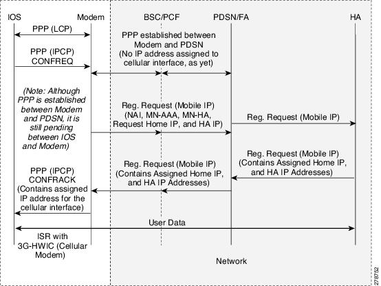
Figure 3-2 shows the data call flow in the CDMA network. The first packet that meets the interesting traffic criteria, as defined by the associated ACLs, causes the dial out to occur via the cellular interface. This causes the PPP to start between the IOS and the modem. After the LCP phase is completed between the Cisco IOS and modem, the IOS starts the PPP IPCP (CONFREQ) phase, bypassing the CHAP/PAP. The CHAP/PAP is bypassed because it is not required for IOS, and therefore not configured under the cellular interface.
After LCP/IPCP messages are received from the Cisco IOS, the modem starts and completes the PPP connection with the network (PDSN). The modem is authenticated by the network during the PPP phase using parameters stored in the modem's NVRAM. These authentication parameters were loaded in the modem's NVRAM after the modem was activated/provisioned. The activation/provisioning of the modem is a one-time process. No IP address is requested by the modem during its IPCP phase with the network. The PPP is established with no IP address and assigned to the modem/IOS.

Note ![]() At this point, the PPP (IPCP) is still pending between the IOS and the modem.
At this point, the PPP (IPCP) is still pending between the IOS and the modem.
After the PPP has been established between the modem and the network, the modem starts the Mobile IP phase. It sends the Mobile IP Registration Request message containing the Network Address Identifier (NAI), MN-AAA, MN-HA shared secrets, and HA IP address and requests an IP address for the modem/IOS (Home IP address). The NAI, MN-AAA, MN-HA shared secrets, and HA IP address are all loaded in the modem's NVRAM as part of modem activation/provisioning.
The Mobile IP Registration Request message is intercepted by the PDSN, which forwards this message to the appropriate HA, as indicated by the HA IP address. The receiving HA validates the user NAI, using the AAA, and returns the Registration Reply message. This assigns the IP address, which is the Home IP address, to the user modem. The PDSN, on receipt of this message, forwards it to the modem, as shown in Figure 3-2.
Finally, the modem sends the PPP IPCP (CONFACK) message to the IOS, completing the pending PPP connection between the IOS and the modem. The modem returns the IP address for the cellular interface, as received from the HA and any other IP addresses, such as DNS, if requested and received.
The address is assigned to the cellular interface and route installed in the routing table.
Note ![]() The IOS is not aware of Mobile IP protocol running across the modem and the HA.
The IOS is not aware of Mobile IP protocol running across the modem and the HA.
Figure 3-2 CDMA Data Call Establishment Call Flow
CDMA Modem Activation and Preparation for Network Connectivity
A newly installed 3G CDMA wireless HWIC requires going through a series of specific steps before connecting to the wireless network. These steps are listed below and described in detail in the following sections.
Step 1 ![]() Obtain wireless data service and the Equipment Serial Number (ESN) of the cellular modem from the service provider.
Obtain wireless data service and the Equipment Serial Number (ESN) of the cellular modem from the service provider.
Step 2 ![]() Ensure that the cellular modem on the HWIC has been registered with the wireless service provider's network.
Ensure that the cellular modem on the HWIC has been registered with the wireless service provider's network.
Step 3 ![]() Activate the modem on the service provider's network via Internet Over-The-Air (IOTA) or Over-The-Air Service Provisioning (OTASP) depending on what your service provider supports.
Activate the modem on the service provider's network via Internet Over-The-Air (IOTA) or Over-The-Air Service Provisioning (OTASP) depending on what your service provider supports.
The 3G HWIC will connect to the best network available on the service provider's network.
Service Plans
The 3G HWIC must be associated with a service plan before it can be activated on a service provider's network. Depending on the mobile operator, there are multiple mobile broadband data plans available: unlimited, metered, or pooled. It may be possible to tie the 3G HWIC service to an existing enterprise wireless contract, which helps keep down the monthly recurring cost (MRC).
The link below lists the mobile operators that have certified the 3G HWIC and provides links to these carrier websites for additional information on the service.
Selecting the Best Radio Network
The 3G HWIC will attempt to connect to the best network available on the service provider's network. If EVDO Rev A is not available, the 3G HWIC will downshift to the next best radio network available, down to 2.5G technology. For instance, if EVDO Rev A is not available, the 3G HWIC will negotiate for EVDO Rev 0, and if that is not available, it will connect via 1xRTT.
Activating the Modem
The 3G CDMA HWIC activation depends on what activation method is supported by your service provider. The types of activation methods are:
•![]() Internet Over-The-Air (IOTA)
Internet Over-The-Air (IOTA)
•![]() Over-The-Air Service Provisioning (OTASP)
Over-The-Air Service Provisioning (OTASP)
Check with your service provider to ensure the type of activation method supported. In the United States, Sprint supports IOTA and Verizon Wireless supports OTASP.
Before attempting the activation, ensure that the HWIC is able to communicate with the network at radio connectivity level. To ensure that the modem is able to communicate, issue the show cellular x/x/x all command.
Example 3-1 Sample Modem Activation Output
The blue italicized text throughout this configuration is used to indicate comments and will not be seen when a normal console output is viewed. The bold text is used to indicate important commands to refer back to in case of an error. When debugging, ensure that all the commands in bold are the same in your console output.
Unless otherwise noted, the bold text refers to commands associated with the basic cellular configuration. The bold text is also used for other configurations such as the crypto IPsec configuration, the backup configuration, the IP SLA configuration, and the mobile IP configuration. Commands associated with each of these configurations are called out throughout the example for ease of reference when debugging.
Router# show cellular 0/1/0 all
!
! Some of the information has been deleted for readability.
!
Hardware Information
====================
Modem Firmware Version = p2005800
Modem Firmware built = 02-09-07
Hardware Version = 1.0
Electronic Serial Number (ESN) = 0x6032691E
Preferred Roaming List (PRL) Version = 60607
Current Modem Temperature = 35 degrees Celsius
!
! Ensure that the PRL and the ESN information is as expected.
!
Profile Information
====================
Electronic Serial Number (ESN) = 0x6032691E
Modem activated = NO
Network Information
===================
Current Service = 1xRTT only
Current Roaming Status(1xRTT) = HOME, (HDR) = HOME
Current Idle Digital Mode = CDMA
Current System Identifier (SID) = 4183
Current Network Identifier (NID) = 87
Current Call Setup Mode = Mobile IP only
Serving Base Station Longitude = -121 deg -55 min -8 sec
Serving Base Station Latitude = 37 deg 25 min 22 sec
Current System Time = Thu Jun 28 7:29:20 2007
!
! The HWIC must be able to get the 1xRTT network service before the service can be
! activated. In this case, only 1xRTT network is available.
!
Radio Information
=================
1xRTT related info
------------------
Current RSSI = -82 dBm, ECIO = -1 dBm
Current Channel Number = 50
Current Channel State = Acquired
Current Band Class = Band Class 1
!
! 1xRTT service has relatively healthy RSSI (Received Signal Strength Indication)
! levels, so service activation is possible.
!
HDR (1xEVDO) related info
-------------------------
Current RSSI = -125 dBm, ECIO = -2 dBm
Current Channel Number = 25
Current Band Class = Band Class 1
Sector ID (Hex) = 0084:0AC0:0000:0000:000A:05DC:A801:1202
Subnet Mask = 104, Color Code = 32, PN Offset = 240
Rx gain control(Main) = Unavailable, Diversity = Unavailable
Tx total power = -5 dBm, Tx gain adjust = -256 dBm
Carrier-to-interference (C/I) ratio = 12
!
! 1xEvDO service is not being sensed (not available in this area), for this particular
! case. Availability of this service is not a requirement for activating the HWIC.
!
Activating Using IOTA
To activate the HWIC using the IOTA procedure, use the following command:
Router# cellular x/x/x cdma activate manual MDN MSIN SID NID MSL
Note ![]() Use the show cellular x/x/x all command to obtain the values for the variables listed below.
Use the show cellular x/x/x all command to obtain the values for the variables listed below.
•![]() Mobile Directory Number (MDN)—10-digit number
Mobile Directory Number (MDN)—10-digit number
•![]() Mobile Subscriber Identification Number (MSIN)—10-digit number
Mobile Subscriber Identification Number (MSIN)—10-digit number
•![]() System ID (SID)
System ID (SID)
•![]() Network ID (NID)
Network ID (NID)
•![]() Mobile Subsidy Lock (MSL)
Mobile Subsidy Lock (MSL)
Example 3-2 Activation Using IOTA Output
The blue italicized text throughout this configuration is used to indicate comments and will not be seen when a normal console output is viewed. The bold text is used to indicate important commands to refer back to in case of an error. When debugging, ensure that all the commands in bold are the same in your console output.
Unless otherwise noted, the bold text refers to commands associated with the basic cellular configuration. The bold text is also used for other configurations such as the crypto IPsec configuration, the backup configuration, the IP SLA configuration, and the mobile IP configuration. Commands associated with each of these configurations are called out throughout the example for ease of reference when debugging.
Router# cellular 0/1/0 cdma activate manual 9134397785 9132262534 4183 87 596027
Modem will be activated with following Parameters
MDN :9134397785; MSIN :9132262534; SID :4183; NID 87:
Aug 18 19:05:50.295: Checking Current Activation Status
Aug 18 19:05:50.347: Modem activation status: Activated
Aug 18 19:05:50.351: Mobile Parameters Unchanged
Aug 18 19:05:50.351: Skip Activation
2851-b1-cdma1#
Aug 18 19:06:00.403: Begin IOTA
Aug 18 19:06:00.403: Please wait till 'IOTA End' event notification is received
Aug 18 19:06:01.247: IOTA Status Message Received. Event = IOTA Start, Result = SUCCESS
Aug 18 19:06:31.567: OTASP State = SPL unlock, Result = Success
Aug 18 19:06:39.847: OTASP State = Parameters commited to NVRAM, Result = Success
Aug 18 19:06:52.015: IOTA Status Message Received. Event = IOTA End, Result = SUCCESS
!
! The modem communicates with the IOTA server and downloads the necessary information
! to the modem.
!
Activation Using OTASP
To activate the HWIC using the OTASP procedure, use the following command:
Router# cellular x/x/x cdma activate otasp phone-number
Note ![]() Use the phone number provided by your service provider for the phone-number variable.
Use the phone number provided by your service provider for the phone-number variable.
Example 3-3 Activation Using OTASP Output
The blue italicized text throughout this configuration is used to indicate comments and will not be seen when a normal console output is viewed. The bold text is used to indicate important commands to refer back to in case of an error. When debugging, ensure that all the commands in bold are the same in your console output.
Unless otherwise noted, the bold text refers to commands associated with the basic cellular configuration. The bold text is also used for other configurations such as the crypto IPsec configuration, the backup configuration, the IP SLA configuration, and the mobile IP configuration. Commands associated with each of these configurations are called out throughout the example for ease of reference when debugging.
Router# cell 0/3/0 cdma activate otasp *22899
Beginning OTASP activation
OTASP number is *22899
ROUTER#Call Connecting - Call State - CnS Async Data Voice Call Packet 1xRtt Call , Number
*22899
Jul 25 18:48:47.563: Begin IOTA
Jul 25 18:48:49.819: Call Connected. Call State - Voice Call OTA Call , Service Option -
Loopback Enhanced Variable Rate Voice (8Kbps) SMS Rate 1 packet Data Service SMS Rate 2
Packet Data Serice (14.4Kbps) Over The Air Parameter Administration - Rate 1 Over The Air
Parameter Administration - Rate 2
Jul 25 18:48:58.091: OTASP State = SPL unlock, Result = Success
Jul 25 18:49:15.483: OTASP State = PRL downloaded, Result = Success
Jul 25 18:49:16.335: OTASP State = Profile downloaded, Result = Success
Jul 25 18:49:16.335: OTASP State = MDN downloaded, Result = Success
Jul 25 18:49:20.279: OTASP State = Parameters commited to NVRAM, Result = Success
Preparation for Network Connectivity
When the 3G HWIC first dials the mobile network after activation, it can take 2 to 5 seconds to establish end-to-end radio and IP connectivity. If the modem needs to redial, then it can take longer than 5 seconds. In addition, the first time the modem is activated on the network, there are provisioning processes as explained in the previous sections which kick off in the background, which will cause the initial end-to-end connectivity to take longer.
After the HWIC has been activated and configured according to the network deployment requirements, the ISR is available for connectivity via the 3G wireless network. Connect the antenna to the HWIC and ensure that RSSI signal level is better than -90 dBm. Ensure that the connectivity to the network indicated by the show cellular x/x/x all command output corresponds to what is shown in Configuring 3G Wireless WAN on Modular and Fixed ISRs (HWIC-3G-CDMA, HWIC-3G-CDMA-x, and PCEX-3G-CDMA-x).
 Feedback