Configuring Cisco EHWIC and 880G for 3.7G (HSPA+)/3.5G (HSPA)
Available Languages
Table Of Contents
Configuring Cisco EHWIC and 880G for
3.7G (HSPA+)/3.5G (HSPA)Modular Cisco ISR G2 Support for the HSPA/HSPA+
EHWICsEHWIC-3G-HSPA-U and C881G-U-K9 Features
Product Descriptions and Supported Frequencies
Remotely Initiated Data Callback Using SMS
Overview of the EHWIC-3G-HSPA-U Card
Overview of the EHWIC-3G-HSPA+7 and EHWIC-3G-HSPA+7-A
Overview of the C881G-U-K9 ISR
C881G-U-K9 Front and Back Panels
Overview of the HSPA+ Versions of the Fixed-Platform ISRs
Installing the Cisco 880G for 3.7G (HSPA+)/3.5G (HSPA) ISRs
Supported Cisco Antennas and Cables
Configuring Cisco EHWIC and 880G for
3.7G (HSPA+)/3.5G (HSPA)Restrictions for Configuring 3G
Overview of UMTS/GSM Data Network
3G Cellular WAN MIB Architecture
(Optional) Voice Initiated Data Callback or Remote Dial-In
Basic Cellular Interface Configuration (HSPA-U)
Basic Cellular Interface Configuration (HSPA+7)
Tunnel over Cellular Interface Configuration
3G Wireless Modem as Backup with NAT and IPSec
cellular gsm sim activate slot
debug cellular messages callcontrol
gsm event connection-status mib-trap
gsm event modem-state mib-trap
Verifying Service Availability
Modem Troubleshooting Using the Diagnostic Port
Configuring Cisco EHWIC and 880G for
3.7G (HSPA+)/3.5G (HSPA)
First Published: August 1, 2011Last Updated: November 21, 2012, OL-24265-03This guide describes how to configure the Universal High Speed Packet Access (HSPA-U) and HSPA Plus (HSPA+) versions of the 3G wireless Enhanced High-Speed WAN Interface Cards (EHWICs). These are multiband, multiservice WAN cards for use over GSM networks.
This guide also describes how to configure the HSPA-U and HSPA+ versions of the Cisco C880G Series Integrated Services Routers (ISRs). These fixed-platform routers contain an embedded multiband, multiservice WAN modem for use over GSM networks.
Contents
•
Modular Cisco ISR G2 Support for the HSPA/HSPA+ EHWICs
•
•
•
•
•
•
•
•
Modular Cisco ISR G2 Support for the HSPA/HSPA+
EHWICsThe EHWIC-3G-HSPA-U, EHWIC-3G-HSPA+7, and EHWIC-3G-HSPA+7-A cards are supported on the following modular Cisco ISR Generation 2 (ISR G2) family of routers:
•
•
•
•
EHWIC-3G-HSPA-U and C881G-U-K9 Features
The EHWIC and 880G for 3.7G (HSPA+)/3.5G (HSPA) cards and ISRs provide the following functionalities:
•
•
•
•
•
•
•
•
•
•
•
–
–
–
•
•
•
•
•
•
•
•
•
–
–
•
•
•
•
•
•
•
•
•
•
•
•
•
•
•
Product Descriptions and Supported Frequencies
Table 1 shows the products discussed in this document and the frequencies they support.
Features
The following features are available in the HSPA-U and HSPA+ versions of the EHWIC and fixed-platform SKUs:
•
•
•
Dual SIM
The Dual SIM feature implements auto-switch and failover between two cellular networks on the
C880G ISRs. This feature is enabled by default with SIM slot 0 being the primary slot and slot 1 being the secondary (failover) slot.The Dual SIM feature provides the following commands:
Note the following:
•
•
•
•
•
This example shows how to set the SIM switchover timeout period to 3 minutes:
router# configure terminalrouter(config-controller)# gsm failovertimer 3This example shows how to authenticate using an unencrypted pin:
router(config-controller)# gsm sim authenticate 0 1234 slot 0This example shows how to set the maximum number of SIM switchover retries to 20:
router(config-controller)# gsm sim max-retry 20This example shows how to set SIM slot 1 as the primary slot:
router(config-controller)# gsm sim primary slot 1This example shows how to configure the SIM card in slot 0 to use profile 10:
router(config-controller)# gsm sim profile 10 slot 0GPS
The GPS feature provides the following commands:
In the syntax of these commands, the value of the unit parameter refers to:
•
•
These examples show how to enable GPS standalone and NMEA for EHWIC-3G-HSPA-U:
router(config)#controller cellular 0/0router(config-controller)#gsm gps mode standalone...controller Cellular 0/0gsm gps mode standalone!router(config-controller)#gsm gps nmea...controller Cellular 0/0gsm gps nmea!These examples show how to display summary and detailed GPS data for C881G-U-K9:
router#show cellular 0 gpsGPS Info-------------GPS State: GPS enabledGPS Mode Configured: standaloneLatitude: 37 Deg 24 Min 59 Sec NorthLongitude: 121 Deg 55 Min 8 Sec WestTimestamp (GMT): Thu Jul 29 11:08:39 2010Fix type: 3D, Height: -6 mHeading: 408, Velocity Horiz: 3, Velocity Vert: 0Satellite Info----------------Satellite #13, elevation 75, azimuth 46, SNR 21...router#show cellular 0 gps detailGPS Info-------------GPS State: GPS enabledGPS Mode Configured: standaloneLatitude: 37 Deg 24 Min 59 Sec NorthLongitude: 121 Deg 55 Min 7 Sec WestTimestamp (GMT): Thu Jul 29 22:17:57 2010Fix type: 3D, Height: 12 mHeading: 0, Velocity Horiz: 0, Velocity Vert: 0HEPE: 2680 cmUncertainty Info:Angle: 0 deg, A: 24 m, Position: 12 m, Vertical: 12 mSatellite Info----------------Satellite #7, elevation 16, azimuth 123, SNR 14 *...
Note
Note
SMS
The SMS feature enables the router to send and receive SMS messages. This feature also enables the router to save and store the SMS messages in an FTP server.
Note
The SMS feature provides the following commands:
In the syntax of these commands, the value of the unit parameter refers to:
•
•
Note
This example shows how to send an SMS message (C881G-U-K9):
router#cellular 0 gsm sms send <phone number> "Test message"This example deletes all SMS messages (EHWIC-3G-HSPA-U):
router#cellular 0/1/0 gsm sms delete allThis example shows how to display a summary of SMS messages (EHWIC-3G-HSPA-U):
router#cellular 0/1/0 gsm sms view summaryID FROM YY/MM/DD HR:MN:SC SIZE CONTENT0 4087993680 10/05/04 21:29:55 32 from John ...1 4087993680 10/05/04 21:52:45 32 from Jane ...2 4087993680 10/05/04 21:56:56 32 from Jake ...3 4087993680 10/05/04 21:56:58 32 from Tom ...4 4087993680 10/05/04 21:57:00 32 from Sam ...The following example sets FTP path to the SMS_archive directory on the FTP server at 192.168.1.3 (C881G-U-K9 and EHWIC-3G-HSPA-U):
router(config-controller)# gsm sms archive path
ftp://username:password@192.168.1.3/SMS_archive
Remotely Initiated Data Callback Using SMS
This feature remotely brings up the cellular interface by sending SMS messages over GSM networks.
Note
dialer caller 4081234567 callback). Replace this number with your own number. To test this example and bring the cellular link up, send an SMS message from your phone.
This example shows how to configure this feature for EHWIC-3G-HSPA-U:
chat-script wcdma "" "atdt*99#" TIMEOUT 180 "CONNECT"interface Loopback1ip address 1.1.1.1 255.255.255.0interface Cellular 0/1/0ip address negotiatedip virtual-reassembly inencapsulation pppload-interval 30dialer in-banddialer pool-member 1dialer idle-timeout 0no peer default ip addressasync mode interactiveppp chap hostname abc.cell.orgppp chap password 0 nopasswordppp ipcp dns requestrouting dynamicinterface Dialer1ip address negotiatedencapsulation pppdialer pool 1dialer idle-timeout 0dialer string wcdmadialer caller 4081234567 callbackdialer-group 1ppp chap hostname abc.cell.orgppp chap password 0 nopasswordppp ipcp dns requestip route 0.0.0.0 0.0.0.0 Dialer1!access-list 1 permit anydialer-list 1 protocol ip list 1!line 0/1/0script dialer wcdmaloginmodem InOutno exectransport input alltransport output all3G WWAN MIB Persistence
This feature allows you to retain 3G WWAN MIB object values and trap settings across router reloads.
Before configuring 3G WWAN MIB, you should perform some SNMP pre-configuration to avoid getting warning messages. The following is an example of SNMP pre-configuration:
snmp-server community public ROsnmp-server community private RWsnmp-server enable traps c3gThis example shows the settings that you need to configure this feature for C881G-U-K9:
controller Cellular 0gsm event rssi onset mib-trap All-gsmgsm event rssi onset threshold -84gsm event rssi abate mib-trap All-gsmgsm event rssi abate threshold -82gsm event temperature onset mib-trapgsm event temperature onset threshold 41gsm event temperature abate mib-trapgsm event temperature abate threshold 40gsm event modem-state mib-trap downgsm event modem-state mib-trap upgsm event service mib-trapgsm event network mib-trapgsm event connection-status mib-trap All-gsm!Overview of the EHWIC-3G-HSPA-U Card
The EHWIC-3G-HSPA-U card version supports the following services:
•
•
•
•
–
–
–
EHWIC-3G-HSPA-U supports multiple services on multiple bands for use in different parts of the world:
•
•
•
•
EHWIC-3G-HSPA-U is the Cisco part number for which the interface card is configured.
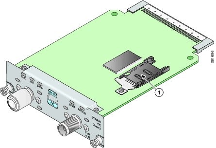
Figure 1 shows the front panel of the EHWIC-3G-HSPA-U.
Figure 1 EHWIC-3G-HSPA-U Front Panel
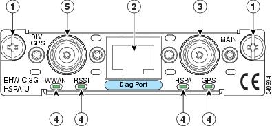
Mounting Screws
LEDs
Diagnostic Port
Diversity/GPS Antenna Connector
Main Antenna Connector
Note
EHWIC-3G-HSPA-U supports the diversity (dual antenna) mode. The types of antennas include the swivel-mounted dipole with extended base and ceiling-mounted antennas. The diversity mode requires two antennas located together and spaced a minimum of 7.5 inches (19 cm) for better RF reception.
Note
Table 2 describes the functions of the LEDs of EHWIC-3G-HSPA-U. The LEDs provide a visual indication of your available services.
For information on how to install the EHWIC-3G-HSPA-U card in supported Cisco Access Routers, see Installing Cisco Interface Cards in Cisco Access Routers.
For information on how to connect the EHWIC-3G-HSPA-U card to your network, see Connecting Cisco EHWIC-3G-HSPA-U to the Network.
Overview of the EHWIC-3G-HSPA+7 and EHWIC-3G-HSPA+7-A
The EHWIC-3G-HSPA+7 and EHWIC-3G-HSPA+7-A cards support the following services:
•
•
•
•
–
–
•
–
–
The EHWIC-3G-HSPA+7-A is localized for AT&T. EHWIC-3G-HSPA+7 and EHWIC-3G-HSPA+7-A cards support multiple services on multiple bands for use in different parts of the world:
•
•
•
•
EHWIC-3G-HSPA+7 and EHWIC-3G-HSPA+7-A are the Cisco part numbers for which these cards are configured. These cards offer higher downlink and uplink throughputs and lower latency than the EHWIC-3G-HSPA-U card. The EHWIC-3G-HSPA+7-A is localized for AT&T.
The EHWIC-3G-HSPA+7 and EHWIC-3G-HSPA+7-A cards support the diversity (dual antenna) mode. Types of antennas include swivel-mounted dipole with extended base and ceiling-mounted antennas. The diversity mode requires two antennas located together and spaced a minimum of 7.5 inches (19 cm) for better RF reception.
Figure 2 shows the front panel view of the EHWIC-3G-HSPA+7 card.
Figure 2 EHWIC-3G-HSPA+7 Front Panel
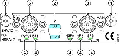
Mounting Screws
LEDs
Diagnostic Port
Diversity/GPS Antenna Connector
Main Antenna Connector
Note
Figure 3 shows the front panel view of the EHWIC-3G-HSPA+7-A card.
Figure 3 EHWIC-3G-HSPA+7-A Front Panel
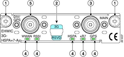
Mounting Screws
LEDs
Diagnostic Port
Diversity/GPS Antenna Connector
Main Antenna Connector
Table 3 describes the LED functions of the EHWIC-3G-HSPA+7 card.
Note
Figure 4 shows the top view of EHWIC-3G-HSPA+7.
Figure 4 Top View of EHWIC-3G-HSPA+7
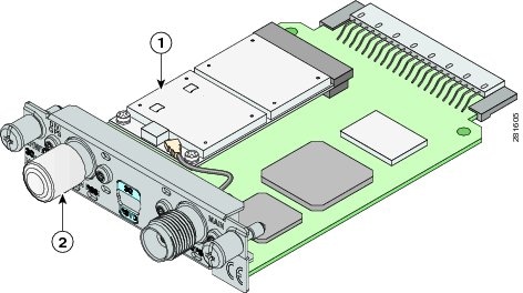
Figure 5 shows the bottom view of the EHWIC-3G-HSPA+7.
Figure 5 Bottom View of EHWIC-3G-HSPA+7
Overview of the C881G-U-K9 ISR
The C881G-U-K9 ISR is a member of the Cisco 880 series data routers. These routers provide integrated Virtual Private Network (VPN), embedded Wi-Fi CERTIFIED™, 802.11b/g/n-compliant wireless Access Point (AP), 3G, and backup capabilities.
For information on configuring Cisco 880 Series ISRs, see Cisco 880 Series Integrated Services Router Software Configuration Guide.
C881G-U-K9 Front and Back Panels
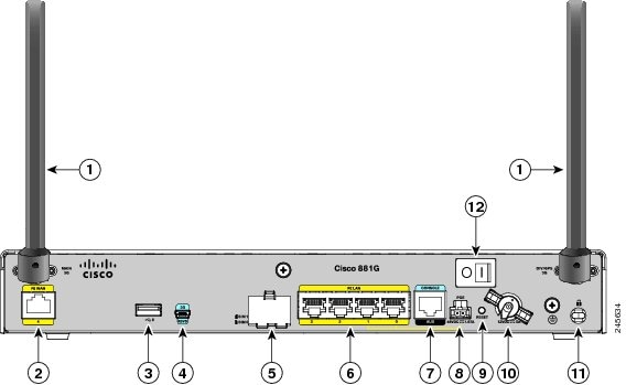
Figure 6 shows the front panel details of the C881G-U-K9 ISR. The front panel has only LEDs. All the ports are in the back panel.
Figure 6 Front Panel of the C881G-U-K9

Table 4 describes the LEDs of the C881G-U-K9 ISR. The LEDs provide a visual indication of the available services.
Figure 7 shows the back panel of the C881G-U-K9.
Figure 7 Back Panel of the C881G-U-K9
Note
Installing the C881G-U-K9 ISR
To install the C881G-U-K9 ISR, follow the instructions in Cisco 860 Series, Cisco 880 Series, and Cisco 890 Series Integrated Services Routers Hardware Installation Guide. This guide describes the equipment and the procedures for installing the Cisco 860 series, 880 series, and 890 series ISRs.
However, the instructions for connecting the 3G card in the hardware installation guide do not apply to the C881G-U-K9 ISR because it does not have a slot for adding a 3G card. Instead, a 3G modem is embedded in the router.
Installing the SIM Cards
You can install one or two SIM cards into the C881G-U-K9 ISR. Installing two SIM cards lets you take advantage of the Dual SIM feature, which provides a failover mechanism in case the primary SIM card fails.
Figure 8 shows the SIM car installation steps.
Figure 8 SIM Card Installation
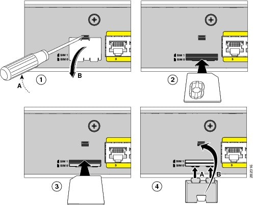
To install the SIM cards, follow these steps:
Step 1
a.
b.
Step 2
Step 3
Step 4
a.
b.
Overview of the HSPA+ Versions of the Fixed-Platform ISRs
The C881G+7-K9, C886VAG+7-K9, C887VAG+7-K9, C887VAMG+7-K9, C888EG+7-K9, C881GW+7-A-K9, C881GW+7-E-K9, C887VAGW+7-A-K9, and C887VAGW+7-E-K9 ISRs are members of the Cisco 880G series data routers. These routers provide integrated VPN, embedded Wi-Fi CERTIFIED™, 802.11b/g/n-compliant wireless AP, 3G, and backup capabilities.
For information on configuring Cisco 880 Series ISRs, see Cisco 880 Series Integrated Services Router Software Configuration Guide.
Front and Back Panels
Figure 9 shows the front panel details of the C881G+7-K9 ISR. The front panel has only LEDs. All the ports are in the back panel.
Figure 9 Front Panel of the C881G+7-K9 ISR
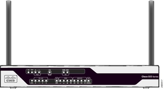
Figure 10 shows the front panel details of the C886VAG+7-K9, C887VAG+7-K9, C887VAMG+7-K9, and C888EG+7-K9 ISRs. The front panel has only LEDs. All the ports are in the back panel.
Figure 10 Front Panel of the C886VAG+7-K9, C887VAG+7-K9, C887VAMG+7-K9, and C888EG+7-K9 ISRs

Figure 11 shows the front panel details of the C881GW+7-A-K9 and C881GW+7-E-K9 ISRs. The front panel has LEDs only. All the ports are in the back panel.
Figure 11 Front Panel of the C881GW+7-A-K9 and C881GW+7-E-K9 ISRs

Figure 12 shows the front panel details of the C887VAGW+7-A-K9 and C887VAGW+7-E-K9 ISRs. The front panel has LEDs only. All the ports are in the back panel.
Figure 12 Front Panel of the C887VAGW+7-A-K9 and C887VAGW+7-E-K9 ISRs
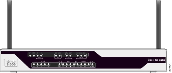
Table 5 describes the LEDs of the C881G+7-K9, C886VAG+7-K9, C887VAG+7-K9, C887VAMG+7-K9, C888EG+7-K9, C881GW+7-A-K9, C881GW+7-E-K9, C887VAGW+7-A-K9, and C887VAGW+7-E-K9 ISRs. The LEDs provide a visual indication of the available services.
Table 5 Cisco 880G for 3.7G (HSPA+)/3.5G (HSPA) LED Description
OK (Power)
Green
On—DC power is being supplied to the router and the Cisco IOS software is running.
Blinking—Bootup is in process, or the router is in ROMMON monitor mode.
Off—Power is not supplied to the router.
PPP
Green
On—At least one PPP session is established.
Off—No PPP session established.
POE
Green
On—PoE is connected and powered.
Off—PoE is not installed.
Amber
On—Power delivery fault with the PoE.
FE4 (WAN Port)1
Green
On—Port is connected.
Blinking—Data is either being received or being transmitted.
Off—Port is not connected.
CD (xDSL)2
Green
Off—Not connected.
Steady On—Connected.
Blink—Training.
DATA (xDSL)3
Green
Off—No data.
Blink—TXD/RXD data.
SIM0/SIM1
Green/Amber
Off—No SIM installed.
Amber—SIM installed but not active.
Green—SIM installed and active.
WLAN (LINK)4
Green
On—Wireless link is up.
Blinking—Ethernet link is up, and data is either being received or being transmitted.
Off—Wireless link is down.
WLAN (2.4GHz/5GHz)5
Green
On—Radio is connected, SSID is configured, and client is associated, but no data is being received or being transmitted.
Slow blinking—Radio is connected, SSID is configured, and beacons are being transmitted.
Fast blinking—Data is either being received or being transmitted.
Off—Radio is shut down and no SSID is configured.
VPN
Green
Off—VPN is not connected.
On—VPN is connected.
FE LAN (FE0:FE3)
Green
On—Ethernet port is connected.
Blinking—Data is either being received or being transmitted.
Off—Ethernet port is not connected.
GPS (3G)
Green (standalone GPS)
Off—GPS not configured.
On—GPS configured.
Blinking—Acquiring GPS data.
RSSI
Green
RSSI status shown by four LEDs [0:3].
Off [0:3]—Very low signal strength
(lower than -110 dBm).On [0], Off [1:3]—Low RSSI
(-110 to -90 dBm).On [0:1], Off [2:3]—Medium RSSI
(-90 to -75 dBm).On [0:2], Off [3]—High RSSI
(-75 to -60 dBm).On [0:3]—Very high RSSI
(-60 dBm or higher).SERVICE
Green/Amber
An array of 4 LEDs [0:3] showing the multiple service levels for each modem type.
Only one LED is on at any time; the LED corresponding to the current trained-up service level.
When no service can be established the Service[0] LED is illuminated Amber, regardless of signal strength.
Service[0]: GPRS/EDGE (2G)
Service[1]: UMTS (3G)
Service[2]: HsxPA (3.5)
Service[3]: +7 (3.7)
WWAN (3G)
Green
Off—Module not powered.
On—Module is powered on and connected but not transmitting or receiving.
Slow Blinking—Module is powered on and searching for connection.
Fast Blinking—Module is transmitting or receiving.
1 C881G+7-K9, C881GW+7-A-K9, and C881GW+7-E-K9 only.
2 C886VAG+7-K9, C887VAG+7-K9, C887VAMG+7-K9, C888EG+7-K9, C887VAGW+7-A-K9, and C887VAGW+7-E-K9 only.
3 C886VAG+7-K9, C887VAG+7-K9, C887VAMG+7-K9, C888EG+7-K9, C887VAGW+7-A-K9, and C887VAGW+7-E-K9 only.
4 C881GW+7-A-K9, C881GW+7-E-K9, C887VAGW+7-A-K9, and C887VAGW+7-E-K9 only.
5 C881GW+7-A-K9, C881GW+7-E-K9, C887VAGW+7-A-K9, and C887VAGW+7-E-K9 only.
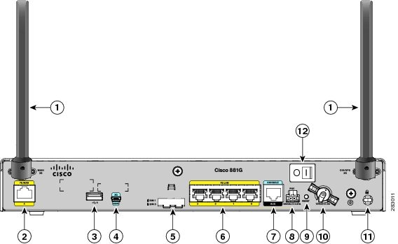
Figure 13 shows the back panel of the C881G+7-K9 ISR.
Figure 13 Back Panel of the C881G+7-K9 ISR
Note
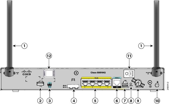
Figure 14 shows the back panel of the C886VAG+7-K9 ISR.
Figure 14 Back Panel of the C886VAG+7-K9 ISR
Note
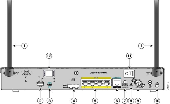
Figure 15 shows the back panel of the C887VAMG+7-K9 ISR.
Figure 15 Back Panel of the C887VAMG+7-K9 ISR
Note
Figure 16 shows the back panel of the C888EG+7-K9 ISR.
Figure 16 Back Panel of the C888EG+7-K9 ISR

Note
Figure 17 shows the back panel of the C881GW+7-A-K9 and C881GW+7-E-K9 ISRs.
Figure 17 Back Panel of the C881GW+7-A-K9 and C881GW+7-E-K9 ISRs
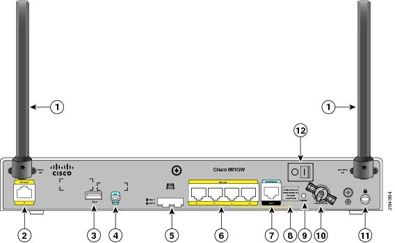
Antenna (the antenna on the left is the main antenna and the one on the right is the DIV/GPS antenna)—connectorized wireless WAN (WWAN) omnidirectional dipole antenna (WWAN models only)
Serial port—console or auxiliary
Primary WAN port—10/100 FE
Note
USB port
Reset button
3G USB diagnostic port
Power connector
SIM 0 and SIM 1 card slots (covered by a metal door as a theft deterrent)
Kensington security slot
4-port 10/100 Ethernet switch
Power switch
Note
Figure 18 shows the back panel of the C887VAGW+7-A-K9 and C887VAGW+7-E-K9 ISRs.
Figure 18 Back Panel of the C887VAGW+7-A-K9 and C887VAGW+7-E-K9 ISRs
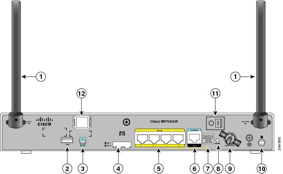
Antenna (the antenna on the left is the main antenna and the one on the right is the DIV/GPS antenna)—connectorized wireless WAN (WWAN) omnidirectional dipole antenna (WWAN models only)
Note
USB port
Reset button
3G USB diagnostic port
Power connector
SIM 0 and SIM 1 card slots (covered by a metal door as a theft deterrent)
Kensington security slot
4-port 10/100 Ethernet switch
Power switch
Serial port—console or auxiliary
VDSL/ADSL port
Note
Installing the Cisco 880G for 3.7G (HSPA+)/3.5G (HSPA) ISRs
To install the C881G+7-K9, C886VAG+7-K9, C887VAG+7-K9, C887VAMG+7-K9, C888EG+7-K9, C881GW+7-A-K9, C881GW+7-E-K9, C887VAGW+7-A-K9, and C887VAGW+7-E-K9 ISRs, follow the instructions in Cisco 860 Series, Cisco 880 Series, and Cisco 890 Series Integrated Services Routers Hardware Installation Guide. This guide describes the equipment and the procedures for installing the Cisco 860 series, 880 series, and 890 series ISRs.
However, the instructions for connecting the 3G card in the hardware installation guide do not apply because these ISRs do not have a slot for adding a 3G card. Instead, a 3G modem is embedded in the router.
Supported Cisco Antennas and Cables
Table 6 lists the Cisco antennas that are supported for use with 3G EHWICs and C880G ISRs.
.
Table 6 Supported Cisco Antennas (3G EHWIC cards and C880G ISRs)
3G-ANTM1916-CM
High-gain
ceiling-mount omnidirectional1.5 dBi
(806-960 MHz)2.5 dBi
(1710-2170 MHz)Multiband ceiling-mounted omnidirectional antenna.
For more information, see Cisco Multiband In-Building Omnidirectional Ceiling-Mount Antenna (3G-ANTM1916-CM).
3G-ANTM1919D
Dipole omnidirectional
0 dBi
(806-960 MHz)0 dBi
(1710-2170 MHz)This is the default antenna. Multiband dipole antenna. For more information, see Cisco Multiband Swivel-Mount Dipole Antenna (3G-ANTM1919D).
3G-AE015-R
(Antenna Extension)Extension base
0.8-6.0 GHz
This antenna extension is a base with a 15-foot cable included for use with a dipole omnidirectional antenna.
For more information, see Cisco Single-Port Antenna Stand for Multiband TNC Male-Terminated Portable Antenna (Cisco 3G-AE015-R).
3G-AE010-R
(Antenna Extension)Extension Base
0.8-6.0 GHz
This is the default antenna extension. This antenna extension is a base with a 10-foot cable included for use with dipole omnidirectional antennas.
For more information, see Cisco Single-Port Antenna Stand for Multiband TNC Male-Terminated Portable Antenna (Cisco 3G-AE015-R). This document applies to both 3G-AE015-R and 3G-AE010-R. The only difference between these two products is the length of the cable.
3G-ANTM-OUT-OM
Outdoor Omnidirectional
+2 dBi
800/900 MHz+4 dBi
1800/1900/2100 MHzThis is an outdoor low profile omnidirectional mast antenna.
For more information, see Cisco 3G Omnidirectional Outdoor Antenna (3G-ANTM-OUT-OM).
3G-ANTM-OUT-LP
Low Profile Stick Antenna
- 1.5 dBi
850, 900 MHz- 2.5 dBi
1800, 1900, 2100 MHzThis is an omnidirectional stick antenna.
For more information, see Cisco Multiband Omnidirectional Panel-Mount Antenna (3G-ANTM-OUT-LP)
3G-ACC-OUT-LA (Lightning Arrestor)
Lightning Arrestor
800 MHz to 2200 MHz
This is a quarter-wave lightning protector with integrated high-pass filter.
For more information, see Cisco 3G Lightning Arrestor (3G-ACC-OUT-LA)
3G-ACC-OUT-COMBO
Lightning Arrestor and antenna
N/A
Multi-Band Outdoor Omnidirectional Antenna Mast/Wall Mount (3G-ACC-OUT-OM) and 3G Outdoor Antenna Lightning Arrestor (3G-ACC-OUT-LA)
4G-ANTM-OM-CM
Low Profile
Surface Mount Omnidirectonal698 MHz-2690 MHz
This is a ceiling mount omnidirectional antenna that can be used in any of the 3G or 4G bands (that is, any of the 700/800/900/1700/1800/1900/2100/2600 MHz bands).
For more information, see Cisco 4G Indoor Ceiling-Mount Omnidirectional Antenna (4G-ANTM-OM-CM).
Table 7 lists insertion loss information for the ultra-low-loss (ULL) LMR 400 extension cables available from Cisco for use with 3G antennas.
Note
Figure 19 and Figure 20 show some antenna options that can be used with C880G ISRs and routers with 3G EHWIC cards.
Figure 19 Antenna Options
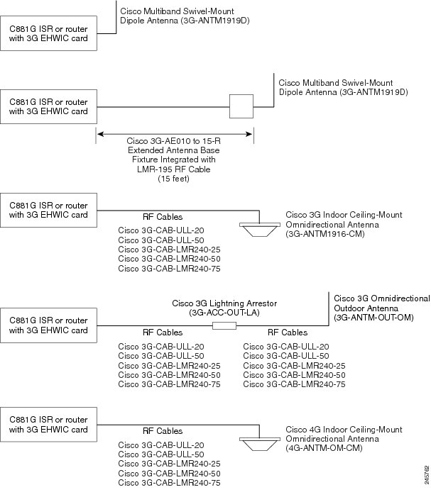
Figure 20 Antenna Options
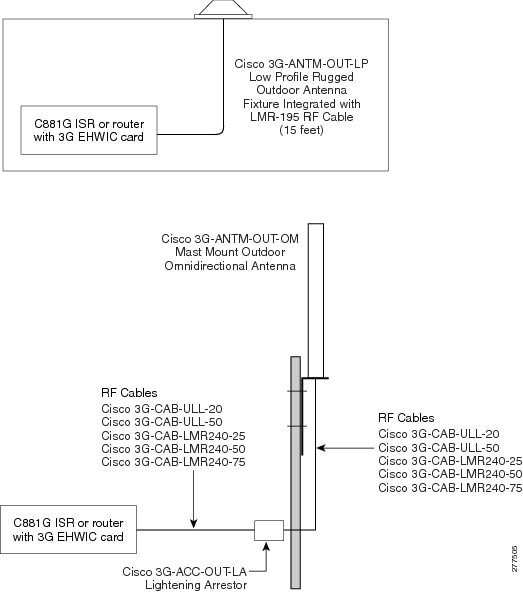
Note
Configuring Cisco EHWIC and 880G for
3.7G (HSPA+)/3.5G (HSPA)•
•
Configuration Prerequisites
The following are prerequisites for configuring Cisco EHWIC and 880G for
3.7G (HSPA+)/3.5G (HSPA):•
http://www.cisco.com/go/3g•
•
•
•
•
•
–
–
–
Restrictions for Configuring 3G
The following restrictions apply to configuring the Cisco 3G EHWIC cards and C880G ISRs:
•
•
•
•
•
Overview of UMTS/GSM Data Network
The Global System for Mobile Communications (GSM) is the most widely deployed cellular network in the world. It is based on the specification from European Telecommunications Standards Institute (ETSI).
GSM was primarily designed for voice and was circuit switched but due to the popularity of cellular networks and the great demand for data services, GPRS was introduced as a packet switched data overlay over the GSM radio network.
The radio and network resources of GPRS are accessed only when data actually needs to be transmitted between the GPRS mobile user and the GPRS network.
GPRS introduced several new network nodes into the GSM architecture for packet switching, they form the Mobile Packet Core. The Mobile Packet Core includes the Serving GPRS Support Node (SGSN) and the GPRS Gateway Support Node (GGSN).
The SGSN is the node that in some ways carries out the same function as the Foreign Agent in Mobile IP. It tunnels IP packets towards the GGSN and detunnels packets back from the GGSN. It also carries out mobility managed and billing.
The GGSN is the node which carries out the role in GPRS equivalent to the Home Agent in Mobile IP. The GGSN provides the connectivity to the IP network and the SGSN. It is responsible for IP address assignment and is the default router for the connected User Equipment (UE).
Figure 21 shows a GSM network and the network elements it contains.
Figure 21 GSM Network Overview
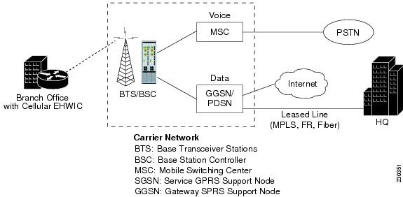
The Base Transceiver Station (BTS) and Base Station Controller (BSC) are located at the Cell site and are the common nodes for both voice and data services. They provide the radio or the physical layer connectivity between the mobile user and the mobile network.
As the BSC voice and data traffic get segregated, the voice traffic goes to the Mobile Switching Center (MSC), while the data traffic is sent to the GGSN. From the GGSN, the data packets either go directly to the internet or they can be backhauled to the customer data center for a VPN connection.
UMTS is a 3G wireless system that delivers high-bandwidth data and voice services to mobile users. UMTS evolved from GSM. UMTS has a new air interface based on GSM and an IP core network based on general-packet radio service (GPRS). The nodes in a UMTS network are almost the same as in a GSM/GPRS network.
BTS and BSC have been renamed to Node B and Radio Network Controller (RNC), respectively. UMTS addresses the growing demand of mobile and Internet applications for new capacity in the overcrowded mobile communications sky. The new network increases transmission speed to 2 Mb/s per mobile user and establishes a global roaming standard.
High Speed Packet Access (HSPA) is a collection of two mobile protocols, High Speed Downlink Packet Access (HSDPA) and High Speed Uplink Packet Access (HSUPA), that extend and improve the performance of existing CDMA/UMTS protocols.
HSDPA and HSUPA provide increased performance by using improved modulation schemes and by refining the protocols by which 3G modem and base stations communicate. These improvements lead to a better utilization of the existing radio bandwidth provided by CDMA.
HSPA improves the end-user experience by increasing peak data rates of up to 14 Mb/s in the downlink and 5.76 Mb/s in the uplink. It also reduces latency and provides up to five times more system capacity in the downlink and up to twice as much system capacity in the uplink, reducing the production cost per bit compared to original CDMA protocols.
Multiple PDP contexts
The dual primary PDP contexts feature is supported on the EHWIC3.7G (HSPA+)/3.5G (HSPA) cards.
Each PDP context is the separate data link over common 3G data connection. It has its own IP address and its own data and QoS profile. For each PDP context, the new IOS cellular interface is created once the EHWIC is initialized in the system. In addition to that, each cellular interface has a corresponding TTY line. This is similar to HWICs with multiple ports.
The EHWIC3.7G (HSPA+)/3.5G (HSPA) cards have Cellular 0/<ehwic_slot>/0, Cellular 0/<ehwic_slot>/1, IOS interfaces. The last number in the triple numbering scheme is the port number.
The multiple cellular interfaces in these 3G HWIC cards behave independently. Any of them can be used to establish data connection. However, only the first interface (for example, Cellular 0/<ehwic_slot>/0), can be used to exercise the full set of modem AT commands using the Reverse Telnet feature.
The HSPA/HSPA+ cellular modem allows you to configure up to16 profiles. The QoS profile configured for an interface is selected by the ATDT*98*#<profile_number>#..."CONNECT" (HSPA modem) or AT!SCACT=1,<profile_number>..."OK" (HSPA+ modem) command in the chat script corresponding to a cellular interface. You must use a different data profile for each cellular interface.
Note
Overview of SNMP MIBs
Simple Management Network Protocol (SNMP) development and use is centered around the MIB. An SNMP MIB is an abstract database, a conceptual specification for information that a management application may read and modify in a certain form.
This does not imply that the information is kept in the managed system in that same form. The SNMP agent translates between the internal data structures and formats of the managed system and the external data structures and formats defined for the MIB.
The SNMP MIB is conceptually a tree structure with conceptual tables. For more informtaion on Cisco 3G MIB, see the "3G Cellular WAN MIB Architecture" section. Relative to this tree structure, the term MIB is used in two senses. In one sense, it is actually a MIB branch, usually containing information for a single aspect of technology, such as a transmission medium or a routing protocol.
A MIB used in this sense is more accurately called a MIB module and is usually defined in a single document. In the other sense, a MIB is a collection of such branches. Such a collection might comprise, for example, all the MIB modules implemented by a given agent or the entire collection of MIB modules defined for SNMP.
A MIB is a tree where the leaves are individual items of data called objects. An object may be, for example, a counter or a protocol status. MIB objects are also sometimes called variables.
MIBs can be classified into three categories:
•
•
•
3G Cellular WAN MIB Architecture
This section describes the MIB definition and implementation support for Cisco's cellular 3G WAN products on the customer premises equipment (CPE) end.
The 3G Cellular WAN MIB supports the CDMA and GSM set of cellular standards and includes the following technologies:
•
•
The 3G cellular MIB uses indexes from the cellular interface and from the modem. You can obtain the interface index using IF MIBs and the modem index using the ENTITY MIBs.
The 3G MIB definition includes the following major sub-trees:
•
•
•
•
You can use MIB object c3gStandard defined in the c3gWanCommonTable to distinguish between CDMA or GSM and implementing MIB for CDMA or GSM.
Note
At a high-level architecture, the Cisco 3G WAN MIBs are divided into two groups and have the following structure:
1.
2.
ciscoWan3gMIBObjects
The ciscoWan3gMIBObjects group has the following sub-groups:
–
–
–
–
–
c3gWanCdmaUnder c3gWanCdma, there are seven sub-groups:
•
•
•
•
•
•
•
c3gWangsmUnder c3gWANgsm, there are five sub-groups:
•
•
•
•
•
c3gWanLbsThe following is a list of the MIB objects under c3gWanLbs:
•
•
•
•
•
•
•
•
•
•
•
•
•
•
•
•
•
•
•
•
•
•
•
•
•
c3gWanSmsThe following is a list of the MIB objects under c3gWanSms:
•
•
•
•
•
•
•
•
•
•
•
•
•
•
•
•
•
ciscoWan3gMIBNotifs
Cisco 3G WAN MIBs implementation supports SNMP GET (read operation) for all MIB objects, and SNMP SET (write operation) for the following RW (read-write) objects and more:
•
•
•
•
•
•
•
•
•
•
•
•
•
•
•
•
•
•
•
•
•
•
•
•
Note
Note
Table 8 shows various 3G WAN MIB traps and what they mean.
Restrictions
•
•
Configuring 3G
Note
For example, for 3G HWICs, the numbering for slot 0, wic 0, and port 0 would be 0/0/0 for all commands. For a fixed Cisco ISR, it would be only 0.
Please refer to platform-specific documentation for details on slot numbering.
To configure the 3G features, follow these procedures:
•
Data Account Provisioning
Note
To provision your data account, follow these procedures:
•
•
Verifying Signal Strength and Service Availability
To verify the signal strength and service availability on your modem, use the following commands in the privileged EXEC mode.
SUMMARY STEPS
1.
2.
3.
4.
5.
DETAILED STEPS
Configuring a Modem Data Profile
To configure or create a new modem data profile, enter the following command in the privileged EXEC mode.
SUMMARY STEPS
1.
DETAILED STEPS
cellular unit gsm profile create profile_number apn authentication username password protocol
Example:Router# cellular 0/0/0 gsm profile create 3 apn.com chap gsm gsmPassword ipv4
Creates a new modem data profile.
For details on the command parameters, see Table 9 .
Data Call Setup
To set up a data call, use the following procedures:
•
•
Figure 22 shows a typical data call setup for EHWIC-3G-HSPA-U.
Figure 22 Data Call Setup with EHWIC-3G-HSPA-U
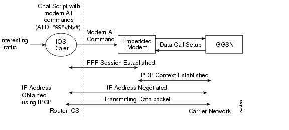
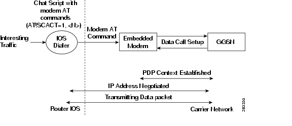
Figure 23 shows a typical data call setup for EHWIC-3G-HSPA+7.
Figure 23 Data Call Setup with EHWIC-3G-HSPA+7
Configuring the Cellular Interface (HSPA-U)
To configure the cellular interface, enter the following commands in the cellular interface mode.
SUMMARY STEPS
1.
2.
3.
4.
5.
6.
7.
Note
DETAILED STEPS
Note
Configuring the Cellular Interface (HSPA+7)
To configure the cellular interface, enter the following commands in the cellular interface mode.
SUMMARY STEPS
1.
2.
3.
4.
5.
DETAILED STEPS
Note
Configuring DDR
To configure dial-on-demand routing (DDR) for the cellular interface, perform the following steps.
SUMMARY STEPS
1.
2.
3.
4.
5.
6.
7.
8.
9.
10.
11.
12.
13.
or
chat-script script name "" "AT!SCACT=1,profile number" TIMEOUT timeout value OK
14.
15.
DETAILED STEPS
Configuring DDR Backup
To monitor the primary connection and initiate the backup connection when needed, the router can use one of the following methods:
•
•
•
To configure DDR backup, perform the following procedures:
•
•
•
Configuring Interfaces to Use a Backup Interface
To configure one or more interfaces to use a backup interface, perform the following steps.
SUMMARY STEPS
1.
2.
3.
DETAILED STEPS
Note
Configuring DDR Backup Using Dialer Watch
To initiate dialer watch, you must configure the interface to perform DDR and backup. Use traditional DDR configuration commands, such as dialer maps, for DDR capabilities. To enable dialer watch on the backup interface and create a dialer list, perform the following steps.
SUMMARY STEPS
1.
2.
3.
4.
5.
6.
7.
8.
DETAILED STEPS
Configuring DDR Backup Using Floating Static Route
To configure a floating static default route on the secondary interface, perform the following steps.
Note
SUMMARY STEPS
1.
2.
DETAILED STEPS
(Optional) Voice Initiated Data Callback or Remote Dial-In
The dial-in feature uses the cellular voice connection request to initiate data call back from an EHWIC.
Note
To configure voice-initiated data callback or remote dial-in on your modem, use the following commands in the privileged EXEC mode.
SUMMARY STEPS
1.
2.
3.
DETAILED STEPS
Note
Configuration Examples
This section provides the following configuration examples:
•
•
•
•
•
Basic Cellular Interface Configuration (HSPA-U)
The following example shows how to configure the HSPA-U-based cellular interface to be used as a primary interface and as the default route:
chat-script gsm "" "ATDT*98*2#" TIMEOUT 60 "CONNECT"!interface Cellular 0/0/0ip address negotiatedencapsulation pppdialer in-banddialer string gsmdialer-group 1async mode interactiveppp chap hostname cisco@wwan.ccsppp chap password 0 ciscoppp ipcp dns request!!!access-list 1 permit anydialer-list 1 protocol ip list 1!line 0/0/0exec-timeout 0 0script dialer gsmloginmodem InOutBasic Cellular Interface Configuration (HSPA+7)
The following example shows how to configure the HSPA+7-based cellular interface to be used as a primary interface and as the default route:
chat-script hspa+ "" "AT!SCACT=1,1" TIMEOUT 60 "OK"interface Cellular0ip address negotiatedencapsulation slipdialer in-banddialer string hspa+dialer-group 1async mode interactiveip route 0.0.0.0 0.0.0.0 Cellular0dialer-list 1 protocol ip permitline 0/0/0 ! for the fixed platforms (88x or 81x) use "line 3" instead of the line 0/0/0exec-timeout 0 0script dialer direct-ipmodem InOutTunnel over Cellular Interface Configuration
The following example shows how to configure the static IP address when a tunnel interface is configured with the ip address unnumbered cellular interface command:
interface Tunnel2ip unnumbered Cellular0/3/0tunnel source Cellular0/3/0tunnel destination 128.107.248.254interface Cellular0/3/0bandwidth receive 1400000ip address 23.23.0.1 255.255.0.0ip nat outsideip virtual-reassemblyencapsulation pppno ip mroute-cachedialer in-banddialer idle-timeout 0dialer string dial<carrier>dialer-group 1async mode interactiveno ppp lcp fast-startppp chap hostname <hostname>ppp chap password 0 <password>ppp ipcp dns request! traffic of interest through the tunnel/cellular interfaceip route 10.10.0.0 255.255.0.0 Tunnel23G Wireless Modem as Backup with NAT and IPSec
The following example shows how to configure the 3G wireless modem on the router as backup with NAT and IPSec.
Note
ip dhcp excluded-address 10.4.0.254!ip dhcp pool gsm poolnetwork 10.4.0.0 255.255.0.0dns-server 66.209.10.201 66.102.163.231default-router 10.4.0.254!!chat-script gsm "" "atdt*98*1#" TIMEOUT 30 "CONNECT"crypto isakmp policy 1encr 3desauthentication pre-sharecrypto isakmp key gsm address 128.107.241.234!!crypto ipsec transform-set gsm ah-sha-hmac esp-3des!crypto map gsm1 10 ipsec-isakmpset peer 128.107.241.234set transform-set gsmmatch address 103!!interface ATM0/0/0no ip addressip virtual-reassemblyload-interval 30no atm ilmi-keepalivedsl operating-mode auto!interface ATM0/0/0.1 point-to-pointbackup interface Cellular0/3/0ip nat outsideip virtual-reassemblyno snmp trap link-statuspvc 0/35pppoe-client dial-pool-number 2!!interface Cellular0/3/0bandwidth receive 1400000ip address negotiatedip nat outsideip virtual-reassemblyencapsulation pppno ip mroute-cachedialer in-banddialer idle-timeout 0dialer string gsmdialer-group 1async mode interactiveno ppp lcp fast-startppp chap hostname cisco@wwan.ccsppp chap password 0 ciscoppp ipcp dns requestcrypto map gsm1!interface Vlan104description used as default gateway address for DHCP clientsip address 10.4.0.254 255.255.0.0ip nat insideip virtual-reassembly!interface Dialer2ip address negotiatedip mtu 1492ip nat outsideip virtual-reassemblyencapsulation pppload-interval 30dialer pool 2dialer-group 2ppp authentication chap callinppp chap hostname cisco@dsl.comppp chap password 0 ciscoppp ipcp dns requestcrypto map gsm1!ip local policy route-map track-primary-ifip route 0.0.0.0 0.0.0.0 Dialer2 track 234ip route 0.0.0.0 0.0.0.0 Cellular0/3/0 254!!ip nat inside source route-map nat2cell interface Cellular0/3/0 overloadip nat inside source route-map nat2dsl interface Dialer2 overload!ip sla 1icmp-echo 209.131.36.158 source-interface Dialer2timeout 1000frequency 2ip sla schedule 1 life forever start-time nowaccess-list 1 permit anyaccess-list 2 permit 10.4.0.0 0.0.255.255access-list 3 permit anyaccess-list 101 permit ip 10.4.0.0 0.0.255.255 anyaccess-list 102 permit icmp any host 209.131.36.158access-list 103 permit ip host 166.138.186.119 128.107.0.0 0.0.255.255access-list 103 permit ip host 75.40.113.246 128.107.0.0 0.0.255.255dialer-list 1 protocol ip list 1dialer-list 2 protocol ip permit!!route-map track-primary-if permit 10match ip address 102set interface Dialer2!route-map nat2dsl permit 10match ip address 101match interface Dialer2!route-map nat2cell permit 10match ip address 101match interface Cellular0/3/0!line 0/3/0exec-timeout 0 0script dialer dial gsmloginmodem InOutVoice-Initiated Data Callback
The following example shows how to configure voice-initiated data callback on the router:
hostname 1900!boot-start-markerboot-end-marker!security passwords min-length 1enable password lab!no aaa new-modelservice-module wlan-ap 0 bootimage autonomous!no ipv6 cefip source-routeip cef!!multilink bundle-name authenticated!chat-script gsm "" "atdt*98*2#" TIMEOUT 180 "CONNECT"!!license udi pid CISCO1941-W sn FHH1249P021!!archivelog confighidekeys!!controller Cellular 0/0!!!interface Loopback1ip address 1.1.1.1 255.255.255.255!interface Wlan-GigabitEthernet0/0description Internal switch interface connecting to the embedded AP!interface GigabitEthernet0/0no ip addressshutdownduplex autospeed auto!interface wlan-ap0description Service module interface to manage the embedded APno ip addressshutdownarp timeout 0no mop enabledno mop sysid!interface GigabitEthernet0/1no ip addressshutdownduplex autospeed auto!interface Cellular0/0/0ip address negotiatedencapsulation pppno ip mroute-cacheload-interval 30dialer in-banddialer pool-member 1dialer-group 1no peer default ip addressfair-queue 64 16 0no ppp lcp fast-startrouting dynamic!interface Vlan1no ip address!interface Dialer1ip address negotiatedencapsulation pppdialer pool 1dialer idle-timeout 0dialer string gsmdialer caller 9994082188382 callbackdialer-group 1!ip forward-protocol ndip route 0.0.0.0 0.0.0.0 Dialer1!no ip http serverno ip http secure-server!!dialer-list 1 protocol ip permit!!snmp-server group steeler3g v3 auth match exact notify 3gViewsnmp-server community public RWsnmp-server community steeler3g-test RWsnmp-server enable traps c3gsnmp-server host 172.27.168.158 public c3gsnmp-server host 172.27.168.158 public udp-port 6059!control-plane!!line con 0exec-timeout 0 0line aux 0line 0/0/0script dialer gsmloginmodem InOutno exectransport input alltransport output allrxspeed 3100000txspeed 1800000line 67no activation-characterno exectransport preferred nonetransport input alltransport output pad telnet rlogin lapb-ta mop udptn v120 sshline vty 0 3password lablogin!exception data-corruption buffer truncatescheduler allocate 20000 1000end1900#Upgrading the Modem Firmware
The fixed and modular ISRs have a 3G modem from Sierra Wireless. The firmware for the modem is upgradable using Cisco IOS commands. The firmware is packaged in a tar distribution file and can be downloaded from the wireless software download page on Cisco.com. Use the following procedure to upgrade the modem firmware:

Caution
Note
Refer to the following website for the latest certified firmware version for your carrier and IOS compatibility:
Step 1
http://www.cisco.com/cisco/software/navigator.html?mdfid=278875243&i=rp.
Note
Step 2
Step 3
Note
Step 4
archive tar /xtract source-url destination-url
Step 5
microcode reload cellular pa-bay slot gsm modem-provision
Caution
Command Reference
This section documents the commands that you can use with Cisco EHWIC and 880G for 3.7G (HSPA+)/3.5G (HSPA).
Note
•
•
•
•
•
cellular gsm band
To select a particular band manually, use the cellular gsm band command in privileged EXEC mode.
cellular unit gsm band band
Syntax Description
Command Modes
Privileged EXEC (#)
Command History
cellular gsm mep unlock
To submit the unlocking code to the service provider when the modem is locked by Mobile Equipment Personalization (MEP), use the cellular gsm mep unlock command in privileged EXEC mode.
cellular unit gsm mep unlock mep-unlock-code
Syntax Description
Command Modes
Privileged EXEC (#)
Command History
Usage Guidelines
•
•
Note
Examples
To verify if the modem MEP is locked, use the show cellular security command. The following output is an example when the modem MEP is locked:
router# show cellular 0 securityCard Holder Verification (CHV1) = DisabledSIM Status = MEP lockedSIM User Operation Required = Enter MEP codeNumber of Retries remaining = 255router#The following example shows the output for this command when you enter a correct MEP PIN:
router# cellular 0 gsm mep unlock 12348765!!!WARNING: Modem will be MEP unlocked with PIN:12348765(8).Interface will be shutdown for MEP unlock.This will terminate any active data connection.Are you sure you want to proceed?[confirm]MEP unlock code has been sent to modem for verficationResetting modem, please wait...*Sep 26 01:36:04.103: %CISCO800-2-MODEM_REMOVAL_DETECTED: Cellular0 modem is now REMOVED*Sep 26 01:36:04.103: %CISCO800-2-MODEM_DOWN: Cellular0 modem is now DOWN.*Sep 26 01:36:05.391: %LINK-5-CHANGED: Interface Cellular0, changed state to administratively down*Sep 26 01:36:10.443: Sierra Wireless 501modem is detected*Sep 26 01:36:10.443: %CISCO800-2-MODEM_INSERTED_DETECTED: Cellular0 modem is now INSERTED*Sep 26 01:36:17.551: %LINK-3-UPDOWN: Interface Cellular0, changed state to down*Sep 26 01:36:45.867: %CISCO800-2-MODEM_UP: Cellular0 modem is now UP.router#router#router#sh cellular 0 securityCard Holder Verification (CHV1) = DisabledSIM Status = OKSIM User Operation Required = NoneNumber of Retries remaining = 3router#Related Commands
cellular gsm plmn search
To search for available public land mobile networks (PLMNs), use the cellular gsm plmn search command in privileged EXEC mode.
cellular unit gsm plmn search
Syntax Description
unit
(EHWIC) Router slot, WIC slot, and port separated by slashes (for example, 0/1/0).
(Fixed platform) The number 0.
Command Modes
Privileged EXEC (#)
Command History
12.4(11)XV
This command was introduced.
12.4(15)T
This command was integrated into Cisco IOS Release 12.4(15)T.
Usage Guidelines
This command searches for available PLMNs or carrier networks at your location. After you issue this command, you must wait for the search completion message and then use the show cellular network command to view the list of the PLMNs available. It may take up to 5 minutes for the search to be completed.
Examples
The following example shows the output for this command:
router# cellular 0/1/0 gsm plmn searchrouter#Dec 12 07:37:15.147: Searching for available PLMNS...Please wait...Dec 12 07:37:45.095: PLMN search done. Please use "show cellular x/x/x network" to see available PLMNSc2800#sh cellular 0/1/0 network<...deleted...>Available PLMN's:PLMN Name = <carrier name>MCC = 310, MNC = 380Status = Registered,, Network = UnknownPLMN Name = <carrier name>MCC = 310, MNC = 380Status = Registered,Supports GPRS, Network = gsmPLMN Name = <carrier name>MCC = 310, MNC = 17Status = Supports GPRS, Network = gsmRelated Commands
cellular gsm plmn select
To manually or automatically select from the available public land mobile network (PLMN) in an area to attach the modem to, use the cellular gsm plmn select command in privileged EXEC mode.
cellular unit gsm plmn select {manual mcc mnc | auto}
Syntax Description
Command Default
By default, PLMN is set to automatic.
Command Modes
Privileged EXEC (#)
Command History
12.4(11)XV
This command was introduced.
12.4(15)T
This command was integrated into Cisco IOS Release 12.4(15)T.
Examples
The following example shows the output for the cellular gsm plmn select manual command. In this example, the user selects PLMN with MCC=310, MNC=17. The show cellular x/x/x network command shows the modem attached to the EDGE network.
Dec 12 07:38:43.799: Selecting PLMN mode to Manual...Please wait...Dec 12 07:38:43.811: PLMN Selection Successfulrouter# show cellular 0/1/0 networkCurrent Service Status = Normal, Service Error = NoneCurrent Service = CombinedPacket Service = EDGE (Attached)Packet Session Status = InactiveCurrent Roaming Status = RoamingNetwork Selection Mode = ManualCountry = USA, Network = CinglrMobile Country Code (MCC) = 310Mobile Network Code (MNC) = 17Location Area Code (LAC) = 230Routing Area Code (RAC) = 1Cell ID = 25573Primary Scrambling Code = 0PLMN Selection = ManualRegistered PLMN = Cingular , Abbreviated = CinglrService Provider = ROGERSThe following example shows the output for the cellular gsm plmn select auto command:
router# cellular 0/1/0 gsm plmn select autorouter#Dec 12 07:46:42.751: Selecting PLMN mode to Auto...Please wait...Dec 12 07:46:42.763: PLMN Selection Successfulrouter#router#sh cellular 0/1/0 networkCurrent Service Status = Normal, Service Error = NoneCurrent Service = CombinedPacket Service = UMTS/WCDMA (Attached)Packet Session Status = InactiveCurrent Roaming Status = RoamingNetwork Selection Mode = AutomaticCountry = USA, Network = CINGULARMobile Country Code (MCC) = 310Mobile Network Code (MNC) = 380Location Area Code (LAC) = 56997Routing Area Code (RAC) = 253Cell ID = 4503Primary Scrambling Code = 169PLMN Selection = AutomaticRegistered PLMN = CINGULAR , Abbreviated = CINGULARService Provider = ROGERSRelated Commands
show cellular network
Displays information about the carrier network and service.
cellular gsm profile create
To create a new modem data profile, use the cellular gsm profile create command in privileged EXEC mode.
cellular unit gsm profile create
profile_number apn authentication username password protocolSyntax Description
Command Modes
Privileged EXEC (#)
Command History
Usage Guidelines
Some of the command parameters, such as username, password, and authentication, are optional and do not need specification. When multiple profiles are created, you can select the profile used to set up the data call by including the profile number in the ATDT command (ATDT*99*profile number#). If you do not include a profile number in the ATDT command (ATDT*99#), profile 1 is used.
This command prompts you before overwriting a defined profile.
Examples
The following example shows the output for this command:
router# cellular 0/0/0 gsm profile create 3 apn.com chap gsm gsmPasswordProfile 3 will be created with the following values:APN = apn.comAuthentication = CHAPUsername = gsmPassword = gsmPasswordAre you sure? [confirm]yProfile 3 written to modemR8795# cellular 0 gsm profile create 1Profile 1 already exists. Do you want to overwrite? [confirm]Profile 1 will be overwritten with the following values:PDP type = IPv4APN =Are you sure? [confirm]Profile 1 written to modemR8795# cellular 0 gsm profile create 1Profile 1 already exists. Do you want to overwrite? [confirm]nProfile 1 is not changed.Related Commands
cellular gsm sim activate slot
To activate the SIM card, use the cellular gsm sim activate slot command in privileged EXEC mode.
cellular unit gsm sim activate slot slot_sum
Syntax Description
unit
(EHWIC) Router slot, WIC slot, and port separated by slashes (for example, 0/1/0).
(Fixed platform) The number 0.
slot_sum
SIM slot number.
Command Modes
Privileged EXEC (#)
Command History
cellular gsm sim change-pin
To change the CHV1 PIN for the SIM, use the cellular gsm sim change-pin command in privileged EXEC mode.
cellular unit gsm sim change-pin old pin new pin
Syntax Description
Command Modes
Privileged EXEC (#)
Command History
Usage Guidelines
You can attempt to change the PIN only three times consecutively after which the SIM will get blocked. The cellular gsm sim change-pin command resets the modem.
cellular gsm sim lock
To lock or unlock the SIM card provided by the service provider, use the cellular gsm sim lock command in privileged EXEC mode.
cellular unit gsm sim lock pin
Syntax Description
Command Modes
Privileged EXEC (#)
Command History
Usage Guidelines
To verify the SIM lock, use the show cellular unit security command.
To change the PIN, use the cellular gsm sim change-pin command.Examples
The following example shows the output for this command:
router# show cellular 0 securityCard Holder Verification (CHV1) = DisabledSIM Status = OKSIM User Operation Required = NoneNumber of Retries remaining = 3router#router#cellular 0 gsm sim lock 1234!!!WARNING: SIM will be locked with pin=1234(4).Do not enter new PIN to lock SIM. Enter PIN that the SIM is configured with.Call will be disconnected!!!Are you sure you want to proceed?[confirm]router#router#router#*Sep 28 17:33:04.052: %CISCO800-2-MODEM_REMOVAL_DETECTED: Cellular0 modem is now REMOVED*Sep 28 17:33:04.056: %CISCO800-2-MODEM_DOWN: Cellular0 modem is now DOWN.*Sep 28 17:33:10.724: Sierra Wireless 501modem is detected*Sep 28 17:33:10.724: %CISCO800-2-MODEM_INSERTED_DETECTED: Cellular0 modem is now INSERTEDrouter#router#*Sep 28 17:33:46.032: %CELLWAN-2-SIM_LOCKED: [Cellular0]: SIM is locked*Sep 28 17:33:46.140: %CISCO800-2-MODEM_UP: Cellular0 modem is now UP.router#router#sh cellular 0 securityCard Holder Verification (CHV1) = Enabled <<<=== lock sim is enabledSIM Status = Locked <<<=== no authentication, user can not use SIMSIM User Operation Required = Enter CHV1 <<<=== enter "gsm sim authentication <0|7> <PIN>Number of Retries remaining = 3router#If the modem is not ready, you will see the following output:
router# cellular 0 gsm sim unlock 1234Cellular0 Modem is still in reset, we recommend to re-execute this cmd after 60 secondsrouter#router(config)#controller cellular 0router(config-controller)#gsm sim authenticate ?0 Specifies an UNENCRYPTED (cleartext) PIN will follow7 Specifies a HIDDEN PIN will followrouter(config-controller)#gsm sim authenticate 0 1234CHV1 configured and sent to modem for verificationrouter(config-controller)#router(config-controller)#endrouter#*Sep 28 17:38:02.516: %SYS-5-CONFIG_I: Configured from console by consolerouter#router#sh cellular 0 securityCard Holder Verification (CHV1) = Enabled <<<=== SIM locked is enabledSIM Status = OK <<<=== authentication is correct, user may use SIMSIM User Operation Required = NoneNumber of Retries remaining = 3router#The following example shows the output for show cellular unit security:
router# show cellular 0/1/0 securityCard Holder Verification (CHV1) = EnabledSIM Status = LockedSIM User Operation Required = Enter CHV1Number of Retries remaining = 3The following example shows how to remove authentication with the SIM still in locked state:
router(config)# controller cellular 0router(config-controller)#no gsm sim authenticate 0 1234WARNING!!!This command will not unlock SIM. Please execute 'cellular <unit> gsm sim unlock <pin>' to unlock SIM.Resetting modem. Call will be disconnected.router(config-controller)#router(config-controller)#*Sep 28 17:40:07.808: %CISCO800-2-MODEM_REMOVAL_DETECTED: Cellular0 modem is now REMOVED*Sep 28 17:40:07.808: %CISCO800-2-MODEM_DOWN: Cellular0 modem is now DOWNrouter(config-controller)#router(config-controller)#endrouter#*Sep 28 17:40:11.256: %SYS-5-CONFIG_I: Configured from console by console*Sep 28 17:40:14.700: Sierra Wireless 501modem is detected*Sep 28 17:40:14.700: %CISCO800-2-MODEM_INSERTED_DETECTED: Cellular0 modem is now INSERTEDrouter#router#*Sep 28 17:40:50.040: %CELLWAN-2-SIM_LOCKED: [Cellular0]: SIM is locked*Sep 28 17:40:50.148: %CISCO800-2-MODEM_UP: Cellular0 modem is now UProuter#
Note
The following example shows the output when the wrong authentication is entered:
router(config)#controller cellular 0router(config-controller)#gsm sim authenticate 0 45689CHV1 configured and sent to modem for verificationrouter(config-controller)#endrouter#*Sep 28 17:42:14.700: %CELLWAN-2-SIM_LOCKED: [Cellular0]: SIM is locked*Sep 28 17:42:14.700: %CELLWAN-2-SIM_CHV1_CONFIG_REMOVED: [Cellular0]: CHV1 verification failed: Incorrect PIN configured. Erased the CHV1 code from router running configuration to avoid SIM blocking during modem reset/powercycle.!!!WARNING: If the incorrect PIN is saved in router start-up configuration, please remove it manually to avoid SIM blocking during router reload*Sep 28 17:42:15.468: %SYS-5-CONFIG_I: Configured from console by consolerouter#The following example shows the output when booting up a router with a locked SIM without authentication configured in Cisco IOS:
router#*Sep 28 21:47:08.411: %CELLWAN-2-SIM_LOCKED: [Cellular0]: SIM is locked*Sep 28 21:47:08.531: %CISCO800-2-MODEM_UP: Cellular0 modem is now UP.*Sep 28 21:47:16.675: %CELLWAN-2-SIM_LOCKED: [Cellular0]: SIM is lockedrouter#router#sh cellular 0 securityCard Holder Verification (CHV1) = EnabledSIM Status = LockedSIM User Operation Required = Enter CHV1Number of Retries remaining = 3 <<<=== no lost to retriesrouter#The following example shows the output when booting up a router with an unlocked SIM with authentication configured in Cisco IOS:
router#*Sep 28 21:14:42.575: %CISCO800-2-MODEM_UP: Cellular0 modem is now UP.*Sep 28 21:14:45.575: %CELLWAN-2-SIM_SECURITY_SHUTDOWN: [Cellular0/0]: CHV1 PIN is configured while SIM is unlocked. Shutting down all PDP interfaces*Sep 28 21:14:47.771: %CELLWAN-2-SIM_SECURITY_SHUTDOWN: [Cellular0/0]: CHV1 PIN is configured while SIM is unlocked. Shutting down all PDP interfaces*Sep 28 21:14:50.611: %CELLWAN-2-SIM_SECURITY_SHUTDOWN: [Cellular0/0]: CHV1 PIN is configured while SIM is unlocked. Shutting down all PDP interfacesrouter#router#sh runBuilding configuration...Current configuration : 2057 bytes!!controller Cellular 0gsm sim authenticate 0 1234 <<<=== config remains with show run!!interface Cellular0ip address negotiatedencapsulation pppshutdown <<<=== PDP context should be shut down!router#router#sh cellular 0 securityCard Holder Verification (CHV1) = DisabledSIM Status = OKSIM User Operation Required = NoneNumber of Retries remaining = 3 <<<=== no lost of retriesrouter#The following example shows the output when locking an already locked SIM:
router# cellular 0 gsm sim lock 1234!!!WARNING: SIM will be locked with pin=1234(4).Do not enter new PIN to lock SIM. Enter PIN that the SIM is configured with.Call will be disconnected!!!Are you sure you want to proceed?[confirm]Lock CHV1 failed: SIM status = Lockedrouter#The following example shows the output when changing the SIM PIN when the SIM is not locked:
router#sh cellular 0 securityCard Holder Verification (CHV1) = DisabledSIM Status = OKSIM User Operation Required = NoneNumber of Retries remaining = 3router#router#router#cellular 0 gsm sim change-pin ?WORD Old PIN (Length 4 to 8 digits)router# cellular 0 gsm sim change-pin 1234 5678 ?<cr>router#cellular 0 gsm sim change-pin 1234 5678!!!WARNING: SIM PIN will be changed from:1234(4) to:5678(4)Call will be disconnected. If old PIN is entered incorrectly in 3 attempt(s), SIM will be blocked!!!Are you sure you want to proceed?[confirm]Change CHV1 failed: CHV1 verification not enabled <<<=== SIM needs to be locked firstrouter#The following example shows the output when the SIM's PIN is changed while in authentication state in Cisco IOS:
Card Holder Verification (CHV1) = EnabledSIM Status = OKSIM User Operation Required = NoneNumber of Retries remaining = 3router#router#cellular 0 gsm sim change-pin 1234 5678!!!WARNING: SIM PIN will be changed from:1234(4) to:5678(4)Call will be disconnected. If old PIN is entered incorrectly in 3 attempt(s), SIM will be blocked!!!Are you sure you want to proceed?[confirm]Change CHV1 failed: Please remove 'gsm sim authenticate' from controller configuration and then retry this commandrouter#
Note
router(config)#controller cellular 0router(config-controller)#no gsm sim authenticate 0 1234 <<<=== this needs to be done first before can change PINWARNING!!!This command will not unlock SIM. Please execute 'cellular <unit> gsm sim unlock <pin>' to unlock SIM.Resetting modem. Call will be disconnected.router(config-controller)#*Sep 28 18:00:44.999: %CISCO800-2-MODEM_REMOVAL_DETECTED: Cellular0 modem is now REMOVED*Sep 28 18:00:44.999: %CISCO800-2-CELLULAR_INTERFACE_NOT_SHUTDOWN: WARNING: Cellular0 interface should be shutdown before removing modem. Reload Required to reset interface*Sep 28 18:00:44.999: %CISCO800-2-MODEM_DOWN: Cellular0 modem is now DOWN.router(config-controller)#endrouter#*Sep 28 18:00:48.167: %SYS-5-CONFIG_I: Configured from console by console*Sep 28 18:00:51.191: Sierra Wireless 501modem is detected*Sep 28 18:00:51.191: %CISCO800-2-MODEM_INSERTED_DETECTED: Cellular0 modem is now INSERTEDrouter#router#*Sep 28 18:01:26.535: %CELLWAN-2-SIM_LOCKED: [Cellular0]: SIM is locked*Sep 28 18:01:26.655: %CISCO800-2-MODEM_UP: Cellular0 modem is now UP.router#router#cellular 0 gsm sim change-pin 1234 5678!!!WARNING: SIM PIN will be changed from:1234(4) to:5678(4)Call will be disconnected. If old PIN is entered incorrectly in 3 attempt(s), SIM will be blocked!!!Are you sure you want to proceed?[confirm]Resetting modem, please wait...CHV1 code change has been completed. Please enter the new PIN in controller configuration for verificationrouter#router#*Sep 28 18:02:32.051: %CISCO800-2-MODEM_REMOVAL_DETECTED: Cellular0 modem is now REMOVED*Sep 28 18:02:32.051: %CISCO800-2-CELLULAR_INTERFACE_NOT_SHUTDOWN: WARNING: Cellular0 interface should be shutdown before removing modem. Reload Required to reset interface*Sep 28 18:02:38.159: Sierra Wireless 501modem is detected*Sep 28 18:02:38.159: %CISCO800-2-MODEM_INSERTED_DETECTED: Cellular0 modem is now INSERTED*Sep 28 18:02:51.655: %CISCO800-2-MODEM_DOWN: Cellular0 modem is now DOWN.Related Commands
cellular gsm sim unblock
To unblock the SIM card provided by the service provider when the CHV1 has been blocked, use the cellular gsm sim unblock command in privileged EXEC mode.
cellular unit gsm sim unblock puk new pin
Syntax Description
Command Modes
Privileged EXEC (#)
Command History
Usage Guidelines
You can verify the unlocked mode by using the show cellular unit security command.
Note
Examples
The following example shows the output for this command:
router# cellular 0/1/0 gsm sim unblock 60265772 1234!!!WARNING: SIM will be unblocked with PUK=60265772(8).If successful, SIM will be locked with new PIN:1234(4)!!!Are you sure you want to proceed?[confirm]Resetting modem, please wait...CHV1 unblock has been completed. Please enter the new PIN in controller configuration for verficationrouter#router#router#*Sep 28 18:11:37.263: %CISCO800-2-MODEM_REMOVAL_DETECTED: Cellular0 modem is now REMOVED*Sep 28 18:11:37.263: %CISCO800-2-CELLULAR_INTERFACE_NOT_SHUTDOWN: WARNING: Cellular0 interface should be shutdown before removing modem. Reload Required to reset interface*Sep 28 18:11:37.263: %CISCO800-2-MODEM_DOWN: Cellular0 modem is now DOWN.*Sep 28 18:11:44.183: Sierra Wireless 501modem is detected*Sep 28 18:11:44.183: %CISCO800-2-MODEM_INSERTED_DETECTED: Cellular0 modem is now INSERTED*Sep 28 18:12:19.467: %CELLWAN-2-SIM_LOCKED: [Cellular0]: SIM is locked*Sep 28 18:12:19.575: %CISCO800-2-MODEM_UP: Cellular0 modem is now UP.router#router#router#sh cellular 0 securityCard Holder Verification (CHV1) = EnabledSIM Status = LockedSIM User Operation Required = Enter CHV1Number of Retries remaining = 3router#Related Commands
cellular gsm sim unlock
To unlock the SIM card provided by the service provider, use the cellular gsm sim unlock command in privileged EXEC mode.
cellular unit gsm sim unlock pin
Syntax Description
Command Modes
Privileged EXEC (#)
Command History
Usage Guidelines
You can verify the unlocked mode by using the show cellular unit security command.
Examples
The following example shows the output for this command:
router# cellular 0/1/0 gsm sim unlock 1234!!!WARNING: SIM will be unlocked with pin=1234(4), call will be disconnected!!!Are you sure you want to proceed?[confirm]Related Commands
cellular gsm sms delete
To delete an SMS message on the GSM band, use the cellular gsm sms delete command in privileged EXEC mode.
cellular unit gsm sms delete {all | message-id}
Syntax Description
unit
(EHWIC) Router slot, WIC slot, and port separated by slashes (for example, 0/1/0).
(Fixed platform) The number 0.
all
Delete all messages.
message-id
ID (0-255) of the message to be deleted.
Command Modes
Privileged EXEC (#)
Command History
Examples
The following example deletes all SMS messages:
router# cellular 0/1/0 gsm sms delete allRelated Commands
cellular gsm sms send
To send an outgoing SMS message on the GSM band, use the cellular gsm sms send command in privileged EXEC mode.
cellular unit gsm sms send destination-number sms-content
Syntax Description
Command Modes
Privileged EXEC (#)
Command History
Examples
The following example shows how to send an SMS message:
router# cellular 0/1/0 gsm sms send 1234567 "Test message"Related Commands
cellular gsm sms view
To display all incoming messages on the GSM band stored on the SIM card, use the cellular gsm sms view command in privileged EXEC mode.
cellular unit gsm sms view {summary | all | message-id}
Syntax Description
Command Modes
Privileged EXEC (#)
Command History
Examples
The following example shows the output for this command:
router# cellular 0/1/0 gsm sms view summaryID FROM YY/MM/DD HR:MN:SC SIZE CONTENT0 4087993680 10/05/04 21:29:55 32 from John ...1 4087993680 10/05/04 21:52:45 32 from Jane ...2 4087993680 10/05/04 21:56:56 32 from Jake ...3 4087993680 10/05/04 21:56:58 32 from Tom ...4 4087993680 10/05/04 21:57:00 32 from Sam ...Related Commands
debug cell-hwic driver
To debug the Cisco IOS driver for the cellular interface, use the debug cell-hwic driver command in privileged EXEC mode.
debug cell-hwic unit driver {crcdump | errdump | errors}
Syntax Description
unit
(EHWIC) Router slot, WIC slot, and port separated by slashes (for example, 0/1/0).
(Fixed platform) The number 0.
crcdump
CRC error details.
errdump
Other error details.
errors
Errors debugging.
Command Modes
Privileged EXEC (#)
Command History
Usage Guidelines
Use this command for debugging purposes only.
Related Commands
debug cell-hwic firmware
To see the Cisco IOS firmware information, use the debug cell-hwic firmware command in privileged EXEC mode.
debug cell-hwic unit firmware
Syntax Description
unit
(EHWIC) Router slot, WIC slot, and port separated by slashes (for example, 0/1/0).
(Fixed platform) The number 0.
Command Modes
Privileged EXEC (#)
Command History
Usage Guidelines
Use this command for debugging purposes only.
Related Commands
debug cell-hwic virt-con
To redirect the Nios II console driver messages to display them in the Cisco IOS router console environment, use the debug cell-hwic virt-con command in privileged EXEC mode.
debug cell-hwic unit virt-con {clear | disable | dump-data-structs | log | monitor | wrapper-on | wrapper-off}
Syntax Description
Command Default
There is no default for this command.
Command Modes
Privileged EXEC (#)
Command History
Usage Guidelines
Use this command for debugging purposes only.
Related Commands
debug cellular messages all
To print all Cisco IOS driver debug messages, use the debug cellular messages all command in privileged EXEC mode.
debug cellular unit messages all
Syntax Description
unit
(EHWIC) Router slot, WIC slot, and port separated by slashes (for example, 0/1/0).
(Fixed platform) The number 0.
Command Modes
Privileged EXEC (#)
Command History
12.4(11)XV
This command was introduced.
12.4(15)T
This command was integrated into Cisco IOS Release 12.4(15)T.
Usage Guidelines
Use this command for debugging purposes only.
Related Commands
debug cellular messages async
To debug cellular async, use the debug cellular messages async command in privileged EXEC mode.
debug cellular unit messages async
Syntax Description
unit
(EHWIC) Router slot, WIC slot, and port separated by slashes (for example, 0/1/0).
(Fixed platform) The number 0.
Command Modes
Privileged EXEC (#)
Command History
12.4(11)XV
This command was introduced.
12.4(15)T
This command was integrated into Cisco IOS Release 12.4(15)T.
Usage Guidelines
Use this command for debugging purposes only.
Related Commands
debug cellular messages callcontrol
To debug cellular direct IP call control, use the debug cellular messages callcontrol command in privileged EXEC mode.
debug cellular unit messages callcontrol
Syntax Description
unit
(EHWIC) Router slot, WIC slot, and port separated by slashes (for example, 0/1/0).
(Fixed platform) The number 0.
Command Modes
Privileged EXEC (#)
Command History
12.4(11)XV
This command was introduced.
12.4(15)T
This command was integrated into Cisco IOS Release 12.4(15)T.
Usage Guidelines
Use this command for debugging purposes only.
Related Commands
debug cellular messages data
To print Cisco IOS data path debug messages, use the debug cellular messages data command in privileged EXEC mode.
debug cellular unit messages data
Syntax Description
unit
(EHWIC) Router slot, WIC slot, and port separated by slashes (for example, 0/1/0).
(Fixed platform) The number 0.
Command Modes
Privileged EXEC (#)
Command History
12.4(11)XV
This command was introduced.
12.4(15)T
This command was integrated into Cisco IOS Release 12.4(15)T.
Usage Guidelines
Use this command for debugging purposes only.
Related Commands
debug cellular messages gps
To display the GPS background activities for debugging purposes, use the debug cellular messages gps command in privileged EXEC mode.
debug cellular unit messages gps
Syntax Description
unit
(EHWIC) Router slot, WIC slot, and port separated by slashes (for example, 0/1/0).
(Fixed platform) The number 0.
Command Modes
Privileged EXEC (#)
Command History
Examples
The following example shows the output for this command:
router# debug cellular 0/1/0 messages gpsGPS debugging is onRelated Commands
debug cellular messages nmea
To display NMEA background activities for debugging purposes, use the debug cellular messages nmea command in privileged EXEC mode.
debug cellular unit messages nmea
Syntax Description
unit
(EHWIC) Router slot, WIC slot, and port separated by slashes (for example, 0/1/0).
(Fixed platform) The number 0.
Command Modes
Privileged EXEC (#)
Command History
Examples
The following example shows the output for this command:
router# debug cellular 0/1/0 messages nmeaRelated Commands
debug cellular messages sms
To display SMS background activities (for example, SMS downloading, deleting, and sending activities) for debugging purposes, use the debug cellular messages sms command in privileged EXEC mode.
debug cellular unit messages sms
Syntax Description
unit
(EHWIC) Router slot, WIC slot, and port separated by slashes (for example, 0/1/0).
(Fixed platform) The number 0.
Command Modes
Privileged EXEC (#)
Command History
Examples
The following example shows the output for this command:
router# debug cellular 0/1/0 messages smsRelated Commands
gsm event connection-status mib-trap
To check the connection status of a 3G WAN MIB trap event, use the gsm event connection-status mib-trap command in controller configuration mode.
gsm event connection-status mib-trap {All-gsm | connected | connecting | disconnected | dormant | error | idle | unknown}
Syntax Description
Command Default
None
Command Modes
Controller configuration (config-controller)
Command History
Examples
The following example shows how to use this command:
router(config-controller)# gsm event connection-status mib-trap idleRelated Commands
gsm event ecio abate
To set the ECIO abate threshold value for sending 3G WAN MIB trap events, use the gsm event ecio abate command in controller configuration mode.
gsm event ecio abate {mib-trap mibtrap | threshold threshold-value}
Syntax Description
Command Modes
Controller configuration (config-controller)
Command History
Examples
The following example configures the router to send MIB trap events on all supported GSM networks when the ECIO value is above the abate threshold of -50 dBm:
router(config-controller)# gsm event ecio abate mib-trap All-gsmrouter(config-controller)# gsm event ecio abate threshold -50The following example configures the router to send MIB trap events on the EDGE network when the ECIO value is above the abate threshold of -100 dBm:
router(config-controller)# gsm event ecio abate mib-trap edgerouter(config-controller)# gsm event ecio abate threshold -100Related Commands
gsm event ecio onset
Sets the ECIO onset threshold value for sending 3G WAN MIB trap events.
gsm event ecio onset
To set the ECIO onset threshold value for sending 3G WAN MIB trap events, use the gsm event ecio onset command in controller configuration mode.
gsm event ecio onset {mib-trap mibtrap | threshold threshold-value}
Syntax Description
Command Modes
Controller configuration (config-controller)
Command History
Examples
The following example configures the router to send MIB trap events on all supported GSM networks when the ECIO value is below the onset threshold of -50 dBm:
router(config-controller)# gsm event ecio onset mib-trap All-gsmrouter(config-controller)# gsm event ecio onset threshold -50The following example configures the router to send MIB trap events on the EDGE network when the ECIO value is below the onset threshold of -100 dBm:
router(config-controller)# gsm event ecio onset mib-trap edgerouter(config-controller)# gsm event ecio onset threshold -100Related Commands
gsm event ecio abate
Sets the ECIO abate threshold value for sending 3G WAN MIB trap events.
gsm event modem-state mib-trap
To set the modem state for sending 3G WAN MIB trap events, use the gsm event modem-state mib-trap command in controller configuration mode.
gsm event modem-state mib-trap {all | up | down}
Syntax Description
all
Sends MIB trap events when the modem is up or down.
up
Sends MIB trap events when the modem is up.
down
Sends MIB trap events when the modem is down.
Command Default
None
Command Modes
Controller configuration (config-controller)
Command History
Examples
The following example configures the router to send MIB trap events only when the modem is down:
router(config-controller)# gsm event modem-state mib-trap downRelated Commands
gsm event network mib-trap
To configure the router to send 3G WAN MIB trap events when network changes occur, use the gsm event network mib-trap command in controller configuration mode.
gsm event network mib-trap
Command Default
None
Command Modes
Controller configuration (config-controller)
Command History
Examples
The following example configures the router to send MIB trap events in response to network changes (for example, switching from an AT&T network to a Verizon network):
router(config-controller)# gsm event network mib-trapRelated Commands
gsm event rssi abate
To set the RSSI abate threshold value for sending 3G WAN MIB trap events, use the gsm event rssi abate command in controller configuration mode.
gsm event rssi abate {mib-trap mibtrap | threshold threshold-value}
Syntax Description
Command Modes
Controller configuration (config-controller)
Command History
Examples
The following example configures the router to send MIB trap events for all supported GSM technologies when the RSSI abate threshold is greater than -50 dBm:
router(config-controller)# gsm event rssi abate mib-trap All-gsmrouter(config-controller)# gsm event rssi abate threshold -50The following example configures the router to send MIB trap events on the EDGE network when the RSSI abate threshold is greater than -100 dBm:
router(config-controller)# gsm event rssi abate mib-trap edgerouter(config-controller)# gsm event rssi abate threshold -100Related Commands
gsm event rssi onset
Sets the RSSI onset threshold value for sending 3G WAN MIB trap events.
gsm event rssi onset
To set the RSSI onset threshold value for sending 3G WAN MIB trap events, use the gsm event rssi onset command in controller configuration mode.
gsm event rssi onset {mib-trap mibtrap | threshold threshold-value}
Syntax Description
Command Modes
Controller configuration (config-controller)
Command History
Examples
The following example configures the router to send MIB trap events on all supported GSM networks when the RSSI value is below the onset threshold of -50 dBm:
router(config-controller)# gsm event rssi onset mib-trap All-gsmrouter(config-controller)# gsm event rssi onset threshold -50The following example configures the router to send MIB trap events on the EDGE network when the RSSI value is below the onset threshold of -100 dBm:
router(config-controller)# gsm event rssi onset mib-trap edgerouter(config-controller)# gsm event rssi onset threshold -100Related Commands
gsm event rssi abate
Sets the RSSI abate threshold value for sending 3G WAN MIB trap events.
gsm event service mib-trap
To configure the router to send 3G WAN MIB trap events when service changes occur, use the gsm event service mib-trap command in controller configuration mode.
gsm event service mib-trap
Command Default
None
Command Modes
Controller configuration (config-controller)
Command History
Examples
The following example configures the router to send MIB trap events in response to service changes (for example, switching from EDGE to GPRS):
router(config-controller)# gsm event network mib-trapRelated Commands
gsm event temperature abate
To set the temperature abate threshold value for sending 3G WAN MIB trap events, use the gsm event temperature abate command in controller configuration mode.
gsm event temperature abate {mib-trap | threshold threshold-value}
Syntax Description
Command Modes
Controller configuration (config-controller)
Command History
Examples
The following example enables temperature abate MIB trap events, then configures the router to send MIB trap events when the temperature goes below 32°F (0°C):
router(config-controller)# gsm event temperature abate mib-traprouter(config-controller)# gsm event temperature abate threshold 0Related Commands
gsm event temperature onset
To set the temperature onset threshold value for sending 3G WAN MIB trap events, use the gsm event temperature onset command in controller configuration mode.
gsm event temperature onset {mib-trap | threshold threshold-value}
Syntax Description
Command Modes
Controller configuration (config-controller)
Command History
Examples
The following example enables temperature onset MIB trap events, then configures the router to send MIB trap events when temperature goes above 32°F (0°C):
router(config-controller)# gsm event temperature onset mib-traprouter(config-controller)# gsm event temperature onset threshold 0Related Commands
gsm failovertimer
To set the timeout period before an ISR with dual SIMs fails over to the secondary SIM, use the gsm failovertimer command in controller configuration mode.
gsm failovertimer 1-7
Syntax Description
Command Modes
Controller configuration (config-controller)
Command History
Usage Guidelines
This command applies to ISRs only.
Examples
The following example shows how to set the SIM switchover timeout period to 3 minutes:
router#conf trouter(config-controller)# gsm failovertimer 3Related Commands
gsm gps mode
To enable the GPS mode, use the gsm gps mode command in privileged EXEC mode.
gsm gps mode standalone
Syntax Description
standalone
Autonomous GPS without assistance data. The Mobile Station (MS) computes its own location; no position determination equipment (PDE) is required. This is the Default mode.
Command Default
Autonomous GPS without assistance data is enabled.
Command Modes
Privileged EXEC (#)
Command History
Examples
The following example enables the standalone GPS mode:
router#conf trouter(config)# gsm gps mode standaloneRelated Commands
debug cellular messages gps
Displays the GPS background activities for debugging purposes.
show cellular gps
Displays GPS statistics.
gsm gps nmea
To enable or disable GPS National Marine Electronics Association (NMEA) stream state, use the gsm gps nmea command in privileged EXEC mode.
gsm gps nmea
Command Modes
Privileged EXEC (#)
Command History
Examples
The following example enables the NMEA stream state:
router# gsm gps nmeaRelated Commands
debug cellular messages nmea
Displays NMEA background activities for debugging purposes.
gsm radio off
To shutdown the radio hardware resources when none of the PDP contexts are in use, particularly in areas where wireless user density is huge, and to turn on power save mode, use the gsm radio off command in controller configuration mode. To turn off the power save mode or to turn on the radio, use the no form of this command.
gsm radio off
no gsm radio off
Command Default
None
Command Modes
Controller configuration (config-controller)
Command History
Usage Guidelines
To check whether power save mode is ON or OFF on an EHWIC or Cisco ISR, use the show controller cellular pabay hwic slot subslot command or the show run command and check for the relevant information.
Note
Examples
The following example shows the output for this command when you enter a correct MEP PIN:
router(config-controller)# gsm radio offWarning: Not all PDP contexts are in shutdown statePlease shutdown all the interfaces manually and re-enter this command.router(config-controller)#router(config-controller)#int c0router(config-if)#shutrouter(config-if)#router(config-if)#exitrouter(config)#controller cellular 0router(config-controller)#gsm radio offWARNING(Controller cellular 0/0): Radio power OFF setting will NOT persists if routeror modem resets. Save to startup configuration.Use "no gsm radio off" to turn radio power ONrouter(config-controller)#endrouter#To verify, use the show run, the show controller, or the show cellular radio commands. The following examples shows the sample output when the radio is turned off for the three commands:
show runrouter#sh runBuilding configuration...!controller Cellular 0gsm radio off <<<===!show controller c0router#sh controller cellular 0Interface Cellular03G Modem-HSPA/UMTS/EDGE/GPRS-850/900/1800/1900/2100MHz / Global,Power save mode is ON <<<====show cellular 0 radiorouter#sh cellular 0 radioRadio power mode = OFF <<<===, Reason = User requestCurrent Band = None, Channel Number = 0Current RSSI = -110 dBmBand Selected = AutoNumber of nearby cells = 1Cell 1Primary Scrambling Code = 0xA9RSCP = -100 dBm, ECIO = -12 dBmrouter#Related Commands
gsm sim authenticate
To store the SIM CHV1 code for verification, use the gsm sim authenticate slot command in controller configuration mode.
gsm sim authenticate 0,7 pin slot 0-1
Syntax Description
Command Modes
Controller configuration (config-controller)
Command History
Usage Guidelines
This command works only when the SIM is locked. If you enter it incorrectly several times, the SIM is blocked. To avoid this, when CHV1 verification fails, you must re-enter the CHV1 code to initiate verification.
Examples
The following example shows how to authenticate using an unencrypted PIN:
router(config-controller)# gsm sim authenticate 0 1234 slot 0Related Commands
gsm sim max-retry
To specify the maximum number of times that the fixed-platform ISR can switch over between its two SIM cards when a SIM card loses service, use the gsm sim max-retry command in controller configuration mode.
gsm sim max-retry 0-65535
Syntax Description
Command Modes
Controller configuration (config-controller)
Command History
Usage Guidelines
When the primary SIM loses service, the ISR automatically tries to switch over to the secondary SIM.
If you do not set the maximum number of tries, the ISR tries to the switchover for a maximum of 10 times (default).
Setting the number of retries to 0 disables the automatic switchover and keeps the service tied to one SIM (the primary SIM).
Every time a SIM switchover occurs, a counter is incremented until it reaches the maximum number of switchover attempts. Then, service is tied to one SIM (the primary SIM) and automatic SIM switchover is stopped.
To see the number of switchover attempts, use the show cellular 0 security command.
Examples
The following example shows how to set the maximum number of SIM switchover retries to 20:
router(config-controller)# gsm sim max-retry 20Related Commands
gsm sim primary slot
To set a SIM slot to be the primary slot on a fixed-platform ISR, such as C881G-U-K9, use the gsm sim primary slot command in controller configuration mode.
gsm sim primary slot 0-1
Syntax Description
Command Modes
Controller configuration (config-controller)
Command History
Examples
The following example shows how to set slot 1 as the primary slot:
router(config-controller)# gsm sim primary slot 1Related Commands
gsm sim profile
To configure the SIM profile, use the gsm sim profile command in controller configuration mode.
gsm sim profile 1-16 slot 0-1
Syntax Description
Command Modes
Controller configuration (config-controller)
Command History
Usage Guidelines
To create a profile, use the cellular gsm profile create command. For more information, see the "Configuring a Modem Data Profile" section.
To display a list of all profiles, use the show cellular profile command.
Examples
The following example shows how to configure the SIM card in slot 0 to use profile 10:
router(config-controller)# gsm sim profile 10 slot 0Related Commands
gsm sms archive path
To configure the FTP settings of the directory used to archive SMS, use the gsm sms archive path command in controller configuration mode.
gsm sms archive path ftp:FTP-path
Syntax Description
Command Default
None
Command Modes
Controller configuration (config-controller)
Command History
Examples
The following example sets the FTP path to the SMS_archive directory on the FTP server at 192.168.1.3:
router(config-controller)#
gsm sms archive path ftp://username:password@192.168.1.3/SMS_archive
Related Commands
show cellular all
To display all the modem information in one listing, use the show cellular all command in privileged EXEC mode.
show cellular unit all
Syntax Description
unit
(EHWIC) Router slot, WIC slot, and port separated by slashes (for example, 0/1/0).
(Fixed platform) The number 0.
Command Modes
Privileged EXEC (#)
Command History
12.4(11)XV
This command was introduced.
12.4(15)T
This command was integrated into Cisco IOS Release 12.4(15)T.
Usage Guidelines
The command usage is the same for Global System for Mobile Communications (GSM) and code division multiple access (CDMA), although the output is different for each.
Examples
The following example shows the output from the show cellular all command for slot 0, WIC slot 0, and port 0:
router# show cellular 0/0/0 allHardware Information====================Modem Firmware Version = U1_2_22MCAP G:/WORKModem Firmware built = 04/17/06Hardware Version = E2International Mobile Subscriber Identity (IMSI) = 001012345678901International Mobile Equipment Identity (IMEI) = 352678010002779Factory Serial Number (FSN) = S2128751274E2OKModem Status = OnlineCurrent Modem Temperature = 28 deg C, State = NormalProfile Information====================Profile 1 = INACTIVE*--------PDP Type = IPv4, Header Compression = OFFData Compression = OFFAccess Point Name (APN) = vpn.comAuthentication = CHAPUsername: wapuser1, Password: wap* - Default profileData Connection Information===========================Data Transmitted = 0 bytes, Received = 0 bytesProfile 1, Packet Session Status = INACTIVEInactivity Reason = Normal inactivate stateProfile 2, Packet Session Status = INACTIVEInactivity Reason = Normal inactivate stateProfile 3, Packet Session Status = INACTIVEInactivity Reason = Normal inactivate stateProfile 4, Packet Session Status = INACTIVEInactivity Reason = Normal inactivate stateProfile 5, Packet Session Status = INACTIVEInactivity Reason = Normal inactivate stateProfile 6, Packet Session Status = INACTIVEInactivity Reason = Normal inactivate stateProfile 7, Packet Session Status = INACTIVEInactivity Reason = Normal inactivate stateProfile 8, Packet Session Status = INACTIVEInactivity Reason = Normal inactivate stateProfile 9, Packet Session Status = INACTIVEInactivity Reason = Normal inactivate stateProfile 10, Packet Session Status = INACTIVEInactivity Reason = Normal inactivate staterouter#Network Information===================Current Service Status = No service, Service Error = NoneCurrent Service = InvalidPacket Service = NonePacket Session Status = InactiveCurrent Roaming Status = HomeNetwork Selection Mode = AutomaticCountry = 0, Network =Mobile Country Code (MCC) = 0Mobile Network Code (MNC) = 0Location Area Code (LAC) = 0Routing Area Code (RAC) = 255Cell ID = 0Primary Scrambling Code = 0PLMN Selection = AutomaticRadio Information=================Current Band = None, Channel Number = 0Current RSSI = -110 dBmModem Security Information==========================Card Holder Verification (CHV1) = DisabledSIM Status = OKSIM User Operation Required = NoneNumber of Retries remaining = 3The following example shows the output of running the show cellular all command on the C881G+R7-K9 ISR:
C881G+R7-K9# show cellular 0 allHardware Information====================Modem Firmware Version = T1_0_3_2AP R361 CNSModem Firmware built = 04/15/11Hardware Version = 1.0International Mobile Subscriber Identity (IMSI) = 310410249752596International Mobile Equipment Identity (IMEI) = 353567040022965Integrated Circuit Card ID (ICCID) = 89014102232497525965Mobile Subscriber International SubscriberIDentity Number (MSISDN) = 14083910358Factory Serial Number (FSN) = CC3291004211001Modem Status = OnlineCurrent Modem Temperature = 33 deg C, State = NormalPRI SKU ID = 9900198, SKU Rev. = 1.1Profile Information====================Profile 1 = INACTIVE*--------PDP Type = IPv4Access Point Name (APN) = isp.cingularAuthentication = CHAPUsername: ISP@CINGULARGPRS.COM, Password: CINGULAR1Profile 2 = INACTIVE--------PDP Type = IPv4Access Point Name (APN) = isp.cingularAuthentication = CHAPUsername: ISP@CINGULARGPRS.COM, Password: CINGULAR1Profile 3 = INACTIVE--------PDP Type = IPv4Access Point Name (APN) = ccspbsc064.acfes.orgAuthentication = CHAPUsername: noname, Password: nopasswordProfile 4 = INACTIVE--------PDP Type = IPv4Access Point Name (APN) = wap.voicestream.comAuthentication = NoneUsername: , Password:Profile 5 = INACTIVE--------PDP Type = IPv4Access Point Name (APN) = epc.tmobile.comAuthentication = NoneUsername: , Password:* - Default profileConfigured default profile for active SIM 0 is profile 1.Data Connection Information===========================Data Transmitted = 243966 bytes, Received = 12900 bytesProfile 1, Packet Session Status = INACTIVEInactivity Reason = Normal inactivate stateProfile 2, Packet Session Status = INACTIVEInactivity Reason = Normal inactivate stateProfile 3, Packet Session Status = INACTIVEInactivity Reason = Normal inactivate stateProfile 4, Packet Session Status = INACTIVEInactivity Reason = Normal inactivate stateProfile 5, Packet Session Status = INACTIVEInactivity Reason = Normal inactivate stateProfile 6, Packet Session Status = INACTIVEInactivity Reason = Normal inactivate stateProfile 7, Packet Session Status = INACTIVEInactivity Reason = Normal inactivate stateProfile 8, Packet Session Status = INACTIVEInactivity Reason = Normal inactivate stateProfile 9, Packet Session Status = INACTIVEInactivity Reason = Normal inactivate stateProfile 10, Packet Session Status = INACTIVEInactivity Reason = Normal inactivate stateProfile 11, Packet Session Status = INACTIVEInactivity Reason = Normal inactivate stateProfile 12, Packet Session Status = INACTIVEInactivity Reason = Normal inactivate stateProfile 13, Packet Session Status = INACTIVEInactivity Reason = Normal inactivate stateProfile 14, Packet Session Status = INACTIVEInactivity Reason = Normal inactivate stateProfile 15, Packet Session Status = INACTIVEInactivity Reason = Normal inactivate stateProfile 16, Packet Session Status = INACTIVEInactivity Reason = Normal inactivate stateNetwork Information===================Current Service Status = No service, Service Error = NoneCurrent Service = CombinedPacket Service = NonePacket Session Status = InactiveCurrent Roaming Status = HomeNetwork Selection Mode = AutomaticCountry = USA, Network = AT&TMobile Country Code (MCC) = 310Mobile Network Code (MNC) = 410Location Area Code (LAC) = 56971Routing Area Code (RAC) = 255Cell ID = 0Primary Scrambling Code = 0PLMN Selection = AutomaticRadio Information=================Radio power mode = ONCurrent Band = None, Channel Number = 0Current RSSI = -110 dBmBand Selected = AutoNumber of nearby cells = 1Cell 1Primary Scrambling Code = 0x106RSCP = -121 dBm, ECIO = -31 dBmModem Security Information==========================Active SIM = 0SIM switchover attempts = 0Card Holder Verification (CHV1) = DisabledSIM Status = OKSIM User Operation Required = NoneNumber of CHV1 Retries remaining = 1GPS Information==========================GPS Info-------------GPS State: GPS disabledSMS Information===============Incoming Message Information----------------------------SMS stored in modem = 5SMS archived since booting up = 0Total SMS deleted since booting up = 0Storage records allocated = 30Storage records used = 5Number of callbacks triggered by SMS = 0Number of successful archive since booting up = 0Number of failed archive since booting up = 0Outgoing Message Information----------------------------Total SMS sent successfully = 0Total SMS send failure = 0Number of outgoing SMS pending = 0Number of successful archive since booting up = 0Number of failed archive since booting up = 0Last Outgoing SMS Status = SUCCESSCopy-to-SIM Status = 0x0Send-to-Network Status = 0x0Report-Outgoing-Message-Number:Reference Number = 0Result Code = 0x0Diag Code = 0x0 0x0 0x0 0x0 0x0SMS Archive URL =Related Commands
show cellular security
Displays the modem lock state.
show controllers cellular
Displays EHWIC hardware and driver-specific information.
show cellular connection
To display the current active connection state and data statistics, use the show cellular connection command in privileged EXEC mode.
show cellular unit connection
Syntax Description
unit
(EHWIC) Router slot, WIC slot, and port separated by slashes (for example, 0/1/0).
(Fixed platform) The number 0.
Command Modes
Privileged EXEC (#)
Command History
12.4(11)XV
This command was introduced.
12.4(15)T
This command was integrated into Cisco IOS Release 12.4(15)T.
Usage Guidelines
The command usage is the same for Global System for Mobile Communications (GSM) and code division multiple access (CDMA), although the output is different for each.
Examples
The following is a sample output for slot 1, wic 0, and port 1:
router# show cellular 1/0/1 connectionData Transmitted = 1066807500 bytes, Received = 1066807500 bytesProfile 1, Packet Session Status = ACTIVEIP address = 1.5.97.2Profile 2, Packet Session Status = INACTIVEInactivity Reason = Normal inactivate stateTable 10 describes each output field.
The following example shows the output of running the show cellular connection command on the C881G+R7-K9 ISR:
C881G+R7-K9# show cellular 0 connectionData Transmitted = 243966 bytes, Received = 12900 bytesProfile 1, Packet Session Status = INACTIVEInactivity Reason = Normal inactivate stateProfile 2, Packet Session Status = INACTIVEInactivity Reason = Normal inactivate stateProfile 3, Packet Session Status = INACTIVEInactivity Reason = Normal inactivate stateProfile 4, Packet Session Status = INACTIVEInactivity Reason = Normal inactivate stateProfile 5, Packet Session Status = INACTIVEInactivity Reason = Normal inactivate stateProfile 6, Packet Session Status = INACTIVEInactivity Reason = Normal inactivate stateProfile 7, Packet Session Status = INACTIVEInactivity Reason = Normal inactivate stateProfile 8, Packet Session Status = INACTIVEInactivity Reason = Normal inactivate stateProfile 9, Packet Session Status = INACTIVEInactivity Reason = Normal inactivate stateProfile 10, Packet Session Status = INACTIVEInactivity Reason = Normal inactivate stateProfile 11, Packet Session Status = INACTIVEInactivity Reason = Normal inactivate stateProfile 12, Packet Session Status = INACTIVEInactivity Reason = Normal inactivate stateProfile 13, Packet Session Status = INACTIVEInactivity Reason = Normal inactivate stateProfile 14, Packet Session Status = INACTIVEInactivity Reason = Normal inactivate stateProfile 15, Packet Session Status = INACTIVEInactivity Reason = Normal inactivate stateProfile 16, Packet Session Status = INACTIVEInactivity Reason = Normal inactivate stateRelated Commands
show cellular gps
To display GPS statistics, use the show cellular gps command in privileged EXEC mode.
show cellular unit gps
Syntax Description
unit
(EHWIC) Router slot, WIC slot, and port separated by slashes (for example, 0/1/0).
(Fixed platform) The number 0.
Command Modes
Privileged EXEC (#)
Command History
Examples
The following example displays the GPS statistics on an EHWIC card:
router# show cellular 0/0/0 gpsThe following example shows the output of running the show cellular gps command on the C881G+R7-K9 ISR:
C881G+R7-K9# show cellular 0 gpsJul 22 09:57:35.371 PST: %SYS-5-CONFIG_I: Configured from console by consoleGPS Info-------------GPS State: GPS acquiringGPS Mode Configured: standaloneLatitude: 0 Deg 0 Min 0 Sec NorthLongitude: 0 Deg 0 Min 0 Sec EastTimestamp (GMT): Sat Jan 5 16:00:00 1980Fix type: 2DSatellite Info----------------Related Commands
debug cellular messages gps
Displays the GPS background activities for debugging purposes.
gsm gps mode
Enables the GPS mode.
show cellular hardware
To display the cellular modem hardware information, use the show cellular hardware command in privileged EXEC mode.
show cellular unit hardware
Syntax Description
unit
(EHWIC) Router slot, WIC slot, and port separated by slashes (for example, 0/1/0).
(Fixed platform) The number 0.
Command Modes
Privileged EXEC (#)
Command History
12.4(11)XV
This command was introduced.
12.4(15)T
This command was integrated into Cisco IOS Release 12.4(15)T.
15.1(3)T1
A new line was added (Endpoint Port Map).
Usage Guidelines
The command usage is the same for Global System for Mobile Communications (GSM) and code division multiple access (CDMA), although the output is different for each.
Examples
The following example shows the output for slot 0, WIC slot 1, and port 0 on an EHWIC-3G-HSPA+7:
router# show cellular 0/0/0 hardwareModem Firmware Version = T1_0_3_2AP R361 CNSZModem Firmware built = 04/15/11Hardware Version = 1.0International Mobile Subscriber Identity (IMSI) = 00112345678901International Mobile Equipment Identity (IMEI) = 353567040022593Integrated Circuit Card ID (ICCID) = 89600109080705907544Mobile Subscriber International SubscriberIDentity Number (MSISDN) =Factory Serial Number (FSN) = CC3291002451001Modem Status = OnlineCurrent Modem Temperature = 22 deg C, State = NormalPRI SKU ID = 9900198, SKU Rev. = 1.1The following example shows the output of running the show cellular hardware command on the C881G+R7-K9 ISR:
C881G+R7-K9# show cellular 0 hardwareModem Firmware Version = T1_0_3_2AP R361 CNSModem Firmware built = 04/15/11Hardware Version = 1.0International Mobile Subscriber Identity (IMSI) = 310410249752596International Mobile Equipment Identity (IMEI) = 353567040022965Integrated Circuit Card ID (ICCID) = 89014102232497525965Mobile Subscriber International SubscriberIDentity Number (MSISDN) = 14083910358Factory Serial Number (FSN) = CC3291004211001Modem Status = OnlineCurrent Modem Temperature = 33 deg C, State = NormalPRI SKU ID = 9900198, SKU Rev. = 1.1Related Commands
show cellular security
Displays the modem lock state.
show controllers cellular
Displays EHWIC hardware- and driver-specific information.
show cellular network
To display information about the carrier network and service, use the show cellular network command in privileged EXEC mode.
show cellular unit network
Syntax Description
unit
(EHWIC) Router slot, WIC slot, and port separated by slashes (for example, 0/1/0).
(Fixed platform) The number 0.
Command Modes
Privileged EXEC (#)
Command History
12.4(11)XV
This command was introduced.
12.4(15)T
This command was integrated into Cisco IOS Release 12.4(15)T.
Usage Guidelines
The command usage is the same for Global System for Mobile Communications (GSM) and code division multiple access (CDMA), although the outputs differ.
Examples
The following example shows the output of the show cellular network command:
router# show cellular 0/0/0 networkCurrent Service Status = Normal, Service Error = NoneCurrent Service = CombinedPacket Service = UMTS/WCDMA (Attached)Packet Session Status = InactiveCurrent Roaming Status = RoamingNetwork Selection Mode = AutomaticCountry = USA, Network = CINGULARMobile Country Code (MCC) = 310Mobile Network Code (MNC) = 380Location Area Code (LAC) = 56997Routing Area Code (RAC) = 253Cell ID = 4503Primary Scrambling Code = 169PLMN Selection = AutomaticRegistered PLMN = Cingular , Abbreviated =Service Provider =Table 11 describes each output field.
The following example shows the output of running the show cellular network command on the C881G+R7-K9 ISR:
C881G+R7-K9# show cellular 0 networkCurrent Service Status = No service, Service Error = NoneCurrent Service = CombinedPacket Service = NonePacket Session Status = InactiveCurrent Roaming Status = HomeNetwork Selection Mode = AutomaticCountry = USA, Network = AT&TMobile Country Code (MCC) = 310Mobile Network Code (MNC) = 410Location Area Code (LAC) = 56971Routing Area Code (RAC) = 255Cell ID = 0Primary Scrambling Code = 0PLMN Selection = AutomaticRelated Commands
show cellular security
Displays the modem lock state.
show controllers cellular
Displays EHWIC hardware and driver-specific information.
show cellular profile
To display the cellular profile information, use the show cellular profile command in privileged EXEC mode.
show cellular unit profile
Syntax Description
unit
(EHWIC) Router slot, WIC slot, and port separated by slashes (for example, 0/1/0).
(Fixed platform) The number 0.
Command Modes
Privileged EXEC (#)
Command History
12.4(11)XV
This command was introduced.
12.4(15)T
This command was integrated into Cisco IOS Release 12.4(15)T.
Usage Guidelines
The command usage is the same for Global System for Mobile Communications (GSM) and code division multiple access (CDMA), although the output is different for each.
Examples
The following example shows how to display a list of profiles configured on an EHWIC card:
router# show cellular 0/1/1 profileProfile 1 = ACTIVE--------PDP Type = IPv4, Header Compression = ONData Compression = ONPDP address = 0x7F000201Access Point Name (APN) = enzo.cisco.comAuthentication = CHAPUsername: cisco, Password: labPrimary DNS address = 127.0.2.1Source Address = 127.0.2.1 255.255.255.0Profile 2 = INACTIVE---------PDP Type = IPv4, Header Compression = ONData Compression = ONPDP address = 0x7F000202Access Point Name (APN) = enzo.cingular.comAuthentication = CHAPUsername: cisco, Password: labPrimary DNS address = 127.0.2.1Source Address = 127.0.2.2 255.255.255.0
The following example shows a list of profiles configured on a fixed-platform ISR:
router# show cellular 0 profileProfile 1 = INACTIVE*--------PDP Type = IPv4Access Point Name (APN) = zzz.netAuthentication = CHAPUsername: 123@zzz.net, Password: 123Profile 2 = INACTIVE--------PDP Type = IPv4Access Point Name (APN) = mmm.netAuthentication = CHAPUsername: 456, Password: 456The following example shows the output of running the show cellular profile command on the C881G+R7-K9 ISR:
C881G+R7-K9# show cellular 0 profileProfile 1 = INACTIVE*--------PDP Type = IPv4Access Point Name (APN) = isp.cingularAuthentication = CHAPUsername: ISP@CINGULARGPRS.COM, Password: CINGULAR1Profile 2 = INACTIVE--------PDP Type = IPv4Access Point Name (APN) = isp.cingularAuthentication = CHAPUsername: ISP@CINGULARGPRS.COM, Password: CINGULAR1Profile 3 = INACTIVE--------PDP Type = IPv4Access Point Name (APN) = ccspbsc064.acfes.orgAuthentication = CHAPUsername: noname, Password: nopasswordProfile 4 = INACTIVE--------PDP Type = IPv4Access Point Name (APN) = wap.voicestream.comAuthentication = NoneUsername: , Password:Profile 5 = INACTIVE--------PDP Type = IPv4Access Point Name (APN) = epc.tmobile.comAuthentication = NoneUsername: , Password:* - Default profileConfigured default profile for active SIM 0 is profile 1.show cellular radio
To display the cellular modem radio statistics, use the show cellular radio command in privileged EXEC mode.
show cellular unit radio [history all | per-hour | per-min | per-sec]
Syntax Description
Command Modes
Privileged EXEC (#)
Command History
12.4(11)XV
This command was introduced.
12.4(15)T
This command was integrated into Cisco IOS Release 12.4(15)T.
Usage Guidelines
The command usage is the same for Global System for Mobile Communications (GSM) and code division multiple access (CDMA), although the output is different for each.
Examples
The following example shows the output for EHWIC-3G-HSPA+7 in slot 0, WIC slot 0, and port 0:
router# show cellular 0/0/0 radioRadio power mode = ONCurrent Band = None, Channel Number = 0Current RSSI = -110 dBmBand Selected = AutoThe following example shows the output of running the show cellular radio command on the C881G+R7-K9 ISR:
C881G+R7-K9# show cellular 0 radioRadio power mode = ONCurrent Band = None, Channel Number = 0Current RSSI = -110 dBmBand Selected = AutoNumber of nearby cells = 1Cell 1Primary Scrambling Code = 0x106RSCP = -121 dBm, ECIO = -31 dBmRelated Commands
show cellular all
Displays the consolidated information about the modem.
show controllers cellular
Displays HWIC-hardware and driver-specific information.
show cellular security
To display the SIM status and modem lock state, use the show cellular security command in privileged EXEC mode.
show cellular unit security
Syntax Description
unit
(EHWIC) Router slot, WIC slot, and port separated by slashes (for example, 0/1/0).
(Fixed platform) The number 0.
Command Modes
Privileged EXEC (#)
Command History
12.4(11)XV
This command was introduced.
12.4(15)T
This command was integrated into Cisco IOS Release 12.4(15)T.
Usage Guidelines
The command usage is the same for Global System for Mobile Communications (GSM) and code division multiple access (CDMA), although the output is different for each.
Examples
The following example shows the output of this command:
router# show cellular 0/0/0 securityCard Holder Verification (CHV1) ENABLEDSIM Status = OKSIM User Operation Required = CHV1Number of Retries remaining = 3Table 13 describes the output from the show cellular security command.
In the case of a fixed-platform ISR, such as C881G-U-K9, the show cellular security command displays the following information:
router# show cellular 0 securityActive SIM = 1SIM switchover attempts = 0Card Holder Verification (CHV1) = DisabledSIM Status = OKSIM User Operation Required = NoneNumber of CHV1 Retries remaining = 1The following example shows the output of running the show cellular security command on the C881G+R7-K9 ISR:
C881G+R7-K9# show cellular 0 securityActive SIM = 0SIM switchover attempts = 0Card Holder Verification (CHV1) = DisabledSIM Status = OKSIM User Operation Required = NoneNumber of CHV1 Retries remaining = 1show cellular sms
To display GPS statistics, including the number of incoming and outgoing messages, use the show cellular sms command in privileged EXEC mode.
show cellular unit sms
Syntax Description
unit
(EHWIC) Router slot, WIC slot, and port separated by slashes (for example, 0/1/0).
(Fixed platform) The number 0.
Command Modes
Privileged EXEC (#)
Command History
Examples
The following example displays the SMS statistics:
router# show cellular 0/0/0 smsc1941#show cellular 0/0/0 smsSMS Service is not availableNumber of outgoing SMS pending = 0c1941#show cellular 0/1/0 smsIncoming Message Information----------------------------SMS stored in modem = 5SMS archived since booting up = 0Total SMS deleted since booting up = 0Storage records allocated = 99Storage records used = 5Number of callbacks triggered by SMS = 0Number of successful archive since booting up = 0Number of failed archive since booting up = 0Outgoing Message Information----------------------------Total SMS sent successfully = 0Total SMS send failure = 0Number of outgoing SMS pending = 0Number of successful archive since booting up = 0Number of failed archive since booting up = 0Last Outgoing SMS Status = SUCCESSSMS-Send-Status:Error Class = 0x0Cause Code = 0x0SMS Archive URL = ftp://username:password@192.168.1.3/SMS_archiveThe following example shows the output of running the show cellular sms command on the C881G+R7-K9 ISR:
C881G+R7-K9# show cellular 0 smsIncoming Message Information----------------------------SMS stored in modem = 5SMS archived since booting up = 0Total SMS deleted since booting up = 0Storage records allocated = 30Storage records used = 5Number of callbacks triggered by SMS = 0Number of successful archive since booting up = 0Number of failed archive since booting up = 0Outgoing Message Information----------------------------Total SMS sent successfully = 0Total SMS send failure = 0Number of outgoing SMS pending = 0Number of successful archive since booting up = 0Number of failed archive since booting up = 0Last Outgoing SMS Status = SUCCESSCopy-to-SIM Status = 0x0Send-to-Network Status = 0x0Report-Outgoing-Message-Number:Reference Number = 0Result Code = 0x0Diag Code = 0x0 0x0 0x0 0x0 0x0SMS Archive URL =C881G+R7-K9#sh controller cellular% Incomplete command.C881G+R7-K9#sh controller cellular 0Interface Cellular03G Modem-QuadBand HSPA+R7/HSPA/UMTS QuadBand EDGE/GPRS Global and GPS,Cellular modem configuration:---------------------------GSM-Carrier Type : Cellular GSM Global.SKU (PRI) Value: 9900198 .Modem is recognized as validmanufacture id: 0x00001199 product id: 0x000068A3Sierra Wireless Mini Card MC8705 HSPA+R7 modem.Cellular Dual SIM details:---------------------------SIM 0 is presentSIM 0 is active SIMCellular Dual SIM register:Dual SIM Control Register ADual SIM Interrupt Register 0Dual SIM Mask Interrupt Register D2Modem Management Statistics---------------------------Modem resets = 2Last known modem state = 'application' modePackets sent = 207, Packets received = 33522, Packets pending = 0DIP MDM link status retry count = 0 pdp context = 0DIP MDM link up pending = 0 pdp context = 0IDB Cellular0: DIP profile id = 255RSSI LED[0-3]: [OFF] [OFF] [OFF] [OFF]Service LED[0-3]: [YELLOW] [OFF] [OFF] [OFF]SIM0 LED: [GREEN]SIM1 LED: [OFF]GPS LED: [GREEN BLINKING]GPS NMEA port = Disabled (Stream OFF)DM port = DisabledAsync HDLC Main Parameter (0xFF516680)------------------------------------INSTNUM=0x01 INSTMASK=0x20EXT1MSNUM=0xF8, EXT2MSNUM=0xF9, EXT3MSNUM=0x3C, EXT4MSNUM=0x3DINST1_BASE=0xFF5166C0, INST2_BASE=0xFF516780Microcode Revision=0x000000ACAsync HDLC Instance (0xFF5166C0) = 0----------------------------------------RBASE=0x6828, TBASE=0x6C28, RBMR=0x30, TBMR=0x30, ZERO=0x00PLAIN_RBASE=0x6A28, AHDLC_TBASE=0x6D28PLRBPTR=0x6A28, AHTXBDPTR=0x6D28AEMODE=0x82, C_MASK=0x0000F0B8, C_PRES=0x0000FFFFTFTHR=0x0001, RFTHR=0x0001, MFLR=0x07F8TXCTL_TBL=0x00000000, RXCTL_TBL=0x00000000 ZERO1=0x0101RFCNT=0x0000, RSTATE=0x30042000, RXRPTR=0x00000000RBPTR=0x6828, RXRCNT=0x0000, RXWPTR=0x00000000RXWCNT=0x0000, RXWTOT=0x0000, RCRC=0x0000FFFFRXPROCNT=0x0000, RXRDAT1=0x00000000, RXRDAT2=0x00000000, RXWDAT1=0x00000000, RXWDAT2=0x00000000TFCNT=0x0000, TSTATE=0x30004000, TXRPTR=0x00000000TBPTR=0x6C28, TXRCNT=0x0000, TXWPTR=0x00000000TXWCNT=0x0000, TXWTOT=0x0000, TCRC=0x0000FFFFTDCNT=0x0000, RXRDPTR=0x66FFRXREM=0x00, RXWDATN0=0x00000000 RXWDATN1=0x00000000TXTEMP=0x00, TXWDAT0=0x00000000, TXWDAT1=0x00000000CEEXM1=0x01FF, CEEXM2=0x01FF, CEEXM3=0x0000, CEEXM4=0x0000CEEXE1=0x0000, CEEXE2=0x0000, CEEXE3=0x0000, CEEXE4=0x0000CIMR=0x80102000, CIPNR=0x00000000CRIMR=0x00C00000, CRIPNR=0x00000000CECDR=0x00800000 CERCR=0x08000000 CECCR=0x80000000Async HDLC Instance (0xFF516780) = 1----------------------------------------RBASE=0x6E28, TBASE=0x7228, RBMR=0x30, TBMR=0x30, ZERO=0x01PLAIN_RBASE=0x7028, AHDLC_TBASE=0x7428PLRBPTR=0x7208, AHTXBDPTR=0x7548AEMODE=0x82, C_MASK=0x0000F0B8, C_PRES=0x0000FFFFTFTHR=0x0001, RFTHR=0x0001, MFLR=0x07F8TXCTL_TBL=0x00000000, RXCTL_TBL=0x00000000 ZERO1=0x0101RFCNT=0x0000, RSTATE=0x30042000, RXRPTR=0x0F3CB328RBPTR=0x6FC8, RXRCNT=0x0000, RXWPTR=0x0F3D5BC0RXWCNT=0x0000, RXWTOT=0x000E, RCRC=0x0000FFFFRXPROCNT=0x0000, RXRDAT1=0x00000000, RXRDAT2=0x0000007E, RXWDAT1=0x000A6B37, RXWDAT2=0x00000700TFCNT=0x0000, TSTATE=0x30004000, TXRPTR=0x0F3BA018TBPTR=0x7348, TXRCNT=0x0000, TXWPTR=0x0F3AEE98TXWCNT=0x0001, TXWTOT=0x0000, TCRC=0x0000FFFFTDCNT=0x0006, RXRDPTR=0x67BFRXREM=0x00, RXWDATN0=0x00000000 RXWDATN1=0x00000001TXTEMP=0x00, TXWDAT0=0x03E80000, TXWDAT1=0x000503E8CEEXM1=0x01FF, CEEXM2=0x01FF, CEEXM3=0x0000, CEEXM4=0x0000CEEXE1=0x0000, CEEXE2=0x0000, CEEXE3=0x0000, CEEXE4=0x0000CIMR=0x80102000, CIPNR=0x00000000CRIMR=0x00C00000, CRIPNR=0x00000000CECDR=0x00800000 CERCR=0x08000000 CECCR=0x80000000idb at 0x86A8FB78, driver data structure at 0x86A923F00 input aborts on receiving flag sequence0 throttles, 0 enables0 overruns, 0 CRC errors0 resource errors, 0 incomp frame errors0 input drops0 transmitter underruns0 tx_abort 0 tx_resetFramer Mode: ATdma channel = 0# of resets for this channel = 0Receive Ringrx ring entries=64, tx ring entries=32rxr head (0)(0xFF516828), rxr tail (4)(0xFF516848)rx bulk complete = 4rx bulk started = 5rx bulk cancelled = 0Plain Receive Ringplain rx ring entries=64, tx ring entries=32plain rxr head (0)(0xFF516A28), plain rxr tail (0)(0xFF516A28)Transmit Ringtxr head (0)(0xFF516C28), txr tail (0)(0xFF516C28)tx count (0), tx mci_txcount (2)tx limited(0)tx null packets processed by USB = 0tx null to process by USB = 0tx bulk complete = 2tx bulk started = 2tx bulk cancelled = 0USB tx throttle = 0USB tx unthrottle count = 2USB tx shadow pak free Q depth 0AHDLC Transmit Ringahdlc txr head (2)(0xFF516D38), ahdlc txr tail (0)(0xFF516D28)dma channel = 1# of resets for this channel = 0Receive Ringrx ring entries=64, tx ring entries=64rxr head (52)(0xFF516FC8), rxr tail (52)(0xFF516FC8)rx bulk complete = 820rx bulk started = 821rx bulk cancelled = 0throttle flag = 0, throttle val = (0x00000000)rx outstanding count = 033529 packet inputs0 input aborts on receiving flag sequence0 throttles0 overruns, 0 CRC errors0 input drops0 input errors414 packet outputs0 transmitter underruns0 transmitter output dropsPlain Receive Ringplain rx ring entries=64, tx ring entries=64plain rxr head (60)(0xFF517208), plain rxr tail (60)(0xFF517208)Transmit Ringtxr head (36)(0xFF517348), txr tail (36)(0xFF517348)tx count (0), tx mci_txcount (2)tx limited(0)tx null packets processed by USB = 0tx null to process by USB = 0tx bulk complete = 100tx bulk started = 100tx bulk cancelled = 0USB tx throttle = 0USB tx unthrottle count = 100USB tx shadow pak free Q depth 0AHDLC Transmit Ringahdlc txr head (36)(0xFF517548), ahdlc txr tail (0)(0xFF517428)dma channel = 3# of resets for this channel = 0Receive Ringrx ring entries=64, tx ring entries=32rxr head (0)(0x00000000), rxr tail (1)(0x00000008)rx bulk complete = 129rx bulk started = 130rx bulk cancelled = 00 packet inputs0 input aborts on receiving flag sequence0 throttles0 overruns, 0 CRC errors0 input drops0 input errors0 packet outputs0 transmitter underruns0 transmitter output dropsPlain Receive Ringplain rx ring entries=64, tx ring entries=32plain rxr head (0)(0x00000000), plain rxr tail (0)(0x00000000)Transmit Ringtxr head (0)(0x00000000), txr tail (0)(0x00000000)tx count (0), tx mci_txcount (2)tx limited(0)tx null packets processed by USB = 0tx null to process by USB = 0tx bulk complete = 969tx bulk started = 969tx bulk cancelled = 0USB tx throttle = 0USB tx unthrottle count = 969USB tx shadow pak free Q depth 0AHDLC Transmit Ringahdlc txr head (9)(0x00000048), ahdlc txr tail (0)(0x00000000)C881G+R7-K9#show run interface cellular 0Building configuration...Current configuration : 302 bytes!interface Cellular0ip address negotiatedip nat outsideip virtual-reassembly inencapsulation slipload-interval 30dialer in-banddialer idle-timeout 0dialer enable-timeout 6dialer string hspa-R7dialer-group 1no peer default ip addressasync mode interactiverouting dynamicendRelated Commands
show controllers cellular
To display EHWIC hardware and driver-specific information, use the show controllers cellular command in privilege EXEC mode.
show controllers cellular unit
Syntax Description
unit
(EHWIC) Router slot, WIC slot, and port separated by slashes (for example, 0/1/0).
(Fixed platform) The number 0.
Command Modes
Privilege EXEC (#)
Command History
12.4(11)XV
This command was introduced.
12.4(15)T
This command was integrated into Cisco IOS Release 12.4(15)T.
Usage Guidelines
Use this command to capture the output for debugging or troubleshooting purposes only.
Related Commands
show interfaces cellular
Displays statistics for the cellular interfaces.
show run interface cellular
Displays the current running configuration for the cellular interface.
show interfaces cellular
To display statistics for the cellular interface, use the show interfaces cellular command in privileged EXEC mode.
show interfaces cellular unit
Syntax Description
unit
(EHWIC) Router slot, WIC slot, and port separated by slashes (for example, 0/1/0).
(Fixed platform) The number 0.
Command Modes
Privileged EXEC (#)
Command History
12.4(11)XV
This command was introduced.
12.4(15)T
This command was integrated into Cisco IOS Release 12.4(15)T.
Usage Guidelines
When you enter this command, encapsulation should be PPP and all signals, such as DCD, DSR, DTR, RTS, and CTS, should be up during normal operation.
Examples
The following example shows the cellular interface statistics in slot 0, WIC slot 1, and port 0:
router# show interfaces cellular 0/1/0Cellular0/1/0 is up, line protocol is upHardware is QuadBand HSPA/UMTS QuadBand EDGE/GPRS and GPSInternet address is 32.177.246.124/32MTU 1500 bytes, BW 5760 Kbit/sec, DLY 100000 usec,reliability 255/255, txload 1/255, rxload 1/255Encapsulation PPP, LCP OpenOpen: IPCP, loopback not setKeepalive not supportedLast input 00:10:29, output 00:10:13, output hang neverLast clearing of "show interface" counters neverInput queue: 1/75/0/0 (size/max/drops/flushes); Total output drops: 0Queueing strategy: weighted fairOutput queue: 0/1000/64/0 (size/max total/threshold/drops)Conversations 0/1/16 (active/max active/max total)Reserved Conversations 0/0 (allocated/max allocated)Available Bandwidth 4320 kilobits/sec30 second input rate 0 bits/sec, 0 packets/sec30 second output rate 0 bits/sec, 0 packets/sec11 packets input, 186 bytes, 0 no bufferReceived 0 broadcasts (0 IP multicasts)0 runts, 0 giants, 0 throttles0 input errors, 0 CRC, 0 frame, 0 overrun, 0 ignored, 0 abort15 packets output, 500 bytes, 0 underruns0 output errors, 0 collisions, 1 interface resets0 unknown protocol drops0 output buffer failures, 0 output buffers swapped out0 carrier transitionsDCD=up DSR=up DTR=up RTS=up CTS=upRelated Commands
show run interface cellular
To see the current running configuration for the cellular interface, use the show run interface cellular command in privileged EXEC mode.
show run interface cellular unit
Syntax Description
unit
(EHWIC) Router slot, WIC slot, and port separated by slashes (for example, 0/1/0).
(Fixed platform) The number 0.
Command Modes
Privileged EXEC (#)
Command History
12.4(11)XV
This command was introduced.
12.4(15)T
This command was integrated into Cisco IOS Release 12.4(15)T.
Examples
The following example shows the output of the show run interface cellular command:
router# show running-config interface cellular 0/0/0interface Cellular0/0/0ip address negotiatedip access-group 10 outip nat outsideip virtual-reassemblyencapsulation pppno ip mroute-cacheload-interval 30dialer in-banddialer idle-timeout 2147483dialer string gsmdialer-group 2async mode interactiveno peer default ip addressfair-queueppp ipcp dns requestrouting dynamicend router#Related Commands
show controllers cellular
Displays EHWIC hardware and driver-specific information.
show interfaces cellular
Displays statistics for the cellular interfaces.
Troubleshooting
This section provides the necessary background information and resources available for troubleshooting the Cisco 3G EHWIC.
Verifying Data Call Setup
To verify the data call setup, perform the following steps:
Step 1
Step 2
•
•
•
•
•
•
•
•
Step 3
Checking Signal Strength
If the Received Signal Strength Indication (RSSI) level is very low (for example, if it is less than -110 dBm) follow these steps:
Step 1
Step 2
Step 3
Verifying Service Availability
The following is a sample output for the show cellular all command for a scenario where the antenna is disconnected and a modem data profile has not been created. The errors in this case have been highlighted with >>>>>>>.
3825_gsm_3# show cellular 0/3/0 allLoad for five secs: 0%/0%; one minute: 0%; five minutes: 1%Time source is hardware calendar, 19:40:43.239 UTC Wed Nov 8 2006Hardware Information====================Modem Firmware Version = H1_0_0_7MCAP G:/WS/Modem Firmware built = 10/26/06Hardware Version = 1.0International Mobile Subscriber Identity (IMSI) = <specific sim number>International Mobile Equipment Identity (IMEI) = <specific modem number>Factory Serial Number (FSN) = X2819460388100DModem Status = OnlineCurrent Modem Temperature = 38 deg C, State = NormalProfile Information====================* - Default profile >>>>>>>> no profile here.Data Connection Information===========================Profile 1, Packet Session Status = INACTIVEInactivity Reason = Normal inactivate stateProfile 2, Packet Session Status = INACTIVEInactivity Reason = Normal inactivate stateProfile 3, Packet Session Status = INACTIVEInactivity Reason = Normal inactivate stateProfile 4, Packet Session Status = INACTIVEInactivity Reason = Normal inactivate stateProfile 5, Packet Session Status = INACTIVEInactivity Reason = Normal inactivate stateProfile 6, Packet Session Status = INACTIVEInactivity Reason = Normal inactivate stateProfile 7, Packet Session Status = INACTIVEInactivity Reason = Normal inactivate stateProfile 8, Packet Session Status = INACTIVEInactivity Reason = Normal inactivate stateProfile 9, Packet Session Status = INACTIVEInactivity Reason = Normal inactivate stateProfile 10, Packet Session Status = INACTIVEInactivity Reason = Normal inactivate stateProfile 11, Packet Session Status = INACTIVEInactivity Reason = Normal inactivate stateProfile 12, Packet Session Status = INACTIVEInactivity Reason = Normal inactivate stateProfile 13, Packet Session Status = INACTIVEInactivity Reason = Normal inactivate stateProfile 14, Packet Session Status = INACTIVEInactivity Reason = Normal inactivate stateProfile 15, Packet Session Status = INACTIVEInactivity Reason = Normal inactivate stateProfile 16, Packet Session Status = INACTIVEInactivity Reason = Normal inactivate stateNetwork Information===================Current Service Status = No service, Service Error = None >>>>>>> no service means not connected to the network.Current Service = CombinedPacket Service = NonePacket Session Status = InactiveCurrent Roaming Status = HomeNetwork Selection Mode = AutomaticCountry = USA, Network = CinglrMobile Country Code (MCC) = 310Mobile Network Code (MNC) = 380Location Area Code (LAC) = 6042Routing Area Code (RAC) = 255Cell ID = 0Primary Scrambling Code = 0PLMN Selection = AutomaticRadio Information=================Current Band = None, Channel Number = 0Current RSSI = -110 dBm >>>>>>> either no antenna, or bad antenna or out of network.Modem Security Information==========================Card Holder Verification (CHV1) = DisabledSIM Status = OKSIM User Operation Required = NoneNumber of Retries remaining = 3Successful Call Setup
The following is a sample output for when a call is set up using a CHAT script. It shows a received IP address from the network. Call setup is successful and the data path is open.
To troubleshoot the call setup, enable these debug commands:
•
•
•
•
•
3825_gsm_3#Nov 8 20:04:42.295: CHAT0/3/0: Attempting async line dialer scriptNov 8 20:04:42.295: CHAT0/3/0: Dialing using Modem script: <carrier> & System script: noneNov 8 20:04:42.299: CHAT0/3/0: process startedNov 8 20:04:42.299: CHAT0/3/0: Asserting DTRNov 8 20:04:42.299: CHAT0/3/0: Chat script <carrier> started >>>>> chat script invokedNov 8 20:04:42.299: CHAT0/3/0: Sending string: atdt*98*1#Nov 8 20:04:42.299: CHAT0/3/0: Expecting string: CONNECTNov 8 20:04:42.343: CHAT0/3/0: Completed match for expect: CONNECTNov 8 20:04:42.343: CHAT0/3/0: Chat script <carrier> finished, status = Success >>>> successful communication with modemNov 8 20:04:42.395: TTY0/3/0: no timer type 1 to destroyNov 8 20:04:42.395: TTY0/3/0: no timer type 0 to destroyNov 8 20:04:42.395: TTY0/3/0: no timer type 2 to destroyNov 8 20:04:44.395: %LINK-3-UPDOWN: Interface Cellular0/3/0, changed state to upNov 8 20:04:44.395: Ce0/3/0 PPP: Using dialer call directionNov 8 20:04:44.395: Ce0/3/0 PPP: Treating connection as a calloutNov 8 20:04:44.395: Ce0/3/0 PPP: Session handle[7E000089] Session id[46]Nov 8 20:04:44.395: Ce0/3/0 PPP: Phase is ESTABLISHING, Active OpenNov 8 20:04:44.395: Ce0/3/0 PPP: No remote authentication for call-outNov 8 20:04:44.395: Ce0/3/0 LCP: O CONFREQ [Closed] id 75 len 16Nov 8 20:04:44.395: Ce0/3/0 LCP: ACCM 0x000A0000 (0x0206000A0000)Nov 8 20:04:44.395: Ce0/3/0 LCP: MagicNumber 0x179E8E46 (0x0506179E8E46)Nov 8 20:04:44.395: Ce0/3/0 LCP: I CONFREQ [REQsent] id 83 len 25Nov 8 20:04:44.395: Ce0/3/0 LCP: ACCM 0x00000000 (0x020600000000)Nov 8 20:04:44.395: Ce0/3/0 LCP: AuthProto CHAP (0x0305C22305)Nov 8 20:04:44.395: Ce0/3/0 LCP: MagicNumber 0x374C7C61 (0x0506374C7C61)Nov 8 20:04:44.395: Ce0/3/0 LCP: PFC (0x0702)Nov 8 20:04:44.395: Ce0/3/0 LCP: ACFC (0x0802)Nov 8 20:04:44.395: Ce0/3/0 LCP: O CONFREJ [REQsent] id 83 len 8Nov 8 20:04:44.395: Ce0/3/0 LCP: PFC (0x0702)Nov 8 20:04:44.395: Ce0/3/0 LCP: ACFC (0x0802)Nov 8 20:04:44.399: Ce0/3/0 LCP: I CONFACK [REQsent] id 75 len 16Nov 8 20:04:44.399: Ce0/3/0 LCP: ACCM 0x000A0000 (0x0206000A0000)Nov 8 20:04:44.399: Ce0/3/0 LCP: MagicNumber 0x179E8E46 (0x0506179E8E46)Nov 8 20:04:44.399: Ce0/3/0 LCP: I CONFREQ [ACKrcvd] id 84 len 21Nov 8 20:04:44.399: Ce0/3/0 LCP: ACCM 0x00000000 (0x020600000000)Nov 8 20:04:44.399: Ce0/3/0 LCP: AuthProto CHAP (0x0305C22305)Nov 8 20:04:44.399: Ce0/3/0 LCP: MagicNumber 0x374C7C61 (0x0506374C7C61)Nov 8 20:04:44.399: Ce0/3/0 LCP: O CONFACK [ACKrcvd] id 84 len 21Nov 8 20:04:44.399: Ce0/3/0 LCP: ACCM 0x00000000 (0x020600000000)Nov 8 20:04:44.399: Ce0/3/0 LCP: AuthProto CHAP (0x0305C22305)Nov 8 20:04:44.399: Ce0/3/0 LCP: MagicNumber 0x374C7C61 (0x0506374C7C61)Nov 8 20:04:44.399: Ce0/3/0 LCP: State is OpenNov 8 20:04:44.399: Ce0/3/0 PPP: Phase is AUTHENTICATING, by the peerNov 8 20:04:44.403: Ce0/3/0 CHAP: I CHALLENGE id 1 len 35 from "UMTS_CHAP_SRVR"Nov 8 20:04:44.403: Ce0/3/0 CHAP: Using hostname from interface CHAPNov 8 20:04:44.403: Ce0/3/0 CHAP: Using password from interface CHAPNov 8 20:04:44.403: Ce0/3/0 CHAP: O RESPONSE id 1 len 40 from "<username configured on the cellular interface>"Nov 8 20:04:44.407: Ce0/3/0 CHAP: I SUCCESS id 1 len 4Nov 8 20:04:44.407: Ce0/3/0 PPP: Phase is FORWARDING, Attempting ForwardNov 8 20:04:44.407: Ce0/3/0 PPP: Phase is ESTABLISHING, Finish LCPNov 8 20:04:44.407: Ce0/3/0 PPP: Phase is UP>>>>> pap/chap succeededNov 8 20:04:44.407: Ce0/3/0 IPCP: O CONFREQ [Closed] id 1 len 22Nov 8 20:04:44.407: Ce0/3/0 IPCP: Address 0.0.0.0 (0x030600000000)Nov 8 20:04:44.407: Ce0/3/0 IPCP: PrimaryDNS 0.0.0.0 (0x810600000000)Nov 8 20:04:44.407: Ce0/3/0 IPCP: SecondaryDNS 0.0.0.0 (0x830600000000)Nov 8 20:04:44.407: Ce0/3/0 PPP: Process pending ncp packetsNov 8 20:04:45.411: Ce0/3/0 IPCP: I CONFNAK [REQsent] id 1 len 16Nov 8 20:04:45.411: Ce0/3/0 IPCP: PrimaryDNS 10.11.12.13 (0x81060A0B0C0D)Nov 8 20:04:45.411: Ce0/3/0 IPCP: SecondaryDNS 10.11.12.14 (0x83060A0B0C0E)Nov 8 20:04:45.411: Ce0/3/0 IPCP: O CONFREQ [REQsent] id 2 len 22Nov 8 20:04:45.411: Ce0/3/0 IPCP: Address 0.0.0.0 (0x030600000000)Nov 8 20:04:45.411: Ce0/3/0 IPCP: PrimaryDNS 10.11.12.13 (0x81060A0B0C0D)Nov 8 20:04:45.411: Ce0/3/0 IPCP: SecondaryDNS 10.11.12.14 (0x83060A0B0C0E)Nov 8 20:04:45.459: Ce0/3/0 IPCP: I CONFREQ [REQsent] id 25 len 4Nov 8 20:04:45.459: Ce0/3/0 IPCP: O CONFACK [REQsent] id 25 len 4Nov 8 20:04:45.459: Ce0/3/0 IPCP: I CONFNAK [ACKsent] id 2 len 22Nov 8 20:04:45.459: Ce0/3/0 IPCP: Address 166.138.186.119 (0x0306A68ABA77)Nov 8 20:04:45.459: Ce0/3/0 IPCP: PrimaryDNS 66.102.163.231 (0x81064266A3E7)Nov 8 20:04:45.459: Ce0/3/0 IPCP: SecondaryDNS 66.102.163.232 (0x83064266A3E8)Nov 8 20:04:45.459: Ce0/3/0 IPCP: O CONFREQ [ACKsent] id 3 len 22Nov 8 20:04:45.459: Ce0/3/0 IPCP: Address 166.138.186.119 (0x0306A68ABA77)Nov 8 20:04:45.459: Ce0/3/0 IPCP: PrimaryDNS 66.102.163.231 (0x81064266A3E7)Nov 8 20:04:45.459: Ce0/3/0 IPCP: SecondaryDNS 66.102.163.232 (0x83064266A3E8)Nov 8 20:04:45.463: Ce0/3/0 IPCP: I CONFACK [ACKsent] id 3 len 22Nov 8 20:04:45.463: Ce0/3/0 IPCP: Address 166.138.186.119 (0x0306A68ABA77)Nov 8 20:04:45.463: Ce0/3/0 IPCP: PrimaryDNS 66.102.163.231 (0x81064266A3E7)Nov 8 20:04:45.463: Ce0/3/0 IPCP: SecondaryDNS 66.102.163.232 (0x83064266A3E8)Nov 8 20:04:45.463: Ce0/3/0 IPCP: State is OpenNov 8 20:04:45.463: Ce0/3/0 IPCP: Install negotiated IP interface address 166.138.186.119Modem Troubleshooting Using the Diagnostic Port
The RJ-45 port on the faceplate of the 3G EHWIC provides access to the debug port on the Sierra Wireless modem. By connecting an industry-standard diagnostic tool like Qualcomm CAIT/QXDM or Spirent UDM to this port, you can perform radio-level diagnostics and traffic monitoring on the modem.
Use the following test commands to enable/disable the DM port:
router# test cell-hwic 0/1/0 dm-port local {on | off | speed}
router# test cell-hwic 0/1/0 dm-port remote {on | off}
For example, to enable the DM port, use one of these commands:
router# test cell-hwic 0/1/0 dm-port local on
router# test cell-hwic 0/1/0 dm-port remote on
The cable used to connect the PC/laptop running the diagnostic tool is the standard Cisco router console cable (RJ-45 to DB-9).
Note
Additional References
Related Documents
Cisco 880 Series Integrated Service Router configuration
•
•
Cisco 800 Series Integrated Service Router installation
Release notes
•
(EVDO Rev A)•
Standards
MIBs
RFCs
No new or modified RFCs are supported, and support for existing RFCs has not been modified.
—
Technical Assistance
Cisco and the Cisco logo are trademarks or registered trademarks of Cisco and/or its affiliates in the U.S. and other countries. To view a list of Cisco trademarks, go to this URL: www.cisco.com/go/trademarks. Third-party trademarks mentioned are the property of their respective owners. The use of the word partner does not imply a partnership relationship between Cisco and any other company. (1110R)
Any Internet Protocol (IP) addresses and phone numbers used in this document are not intended to be actual addresses and phone numbers. Any examples, command display output, network topology diagrams, and other figures included in the document are shown for illustrative purposes only. Any use of actual IP addresses or phone numbers in illustrative content is unintentional and coincidental.
© 2011-2012 Cisco Systems, Inc. All rights reserved.
 Feedback