- Preface
- Cisco ONS Documentation Roadmap for Release 9.2.1
- Chapter 1, Install the Shelf and Backplane Cable
- Chapter 2, Install Cards and Fiber-Optic Cable
- Chapter 3, Connect the PC and Log Into the GUI
- Chapter 4, Turn Up a Node
- Chapter 5, Turn Up a Network
- Chapter 6, Create Circuits and VT Tunnels
- Chapter 7, Manage Circuits
- Chapter 8, Manage Alarms
- Chapter 9, Monitor Performance
- Chapter 10, Change Card Settings
- Chapter 11, Change Node Settings
- Chapter 12, Upgrade Cards and Spans
- Chapter 13, Upgrade Network and Configurations
- Chapter 14, Add and Remove Nodes
- Chapter 15, Maintain the Node
- Chapter 16, Power Down the Node
- Chapter 17, DLPs A1 to A99
- Chapter 18, DLPs A100 to A199
- Chapter 19, DLPs A200 to A299
- Chapter 20, DLPs A300 to A399
- Chapter 21, DLPs A400 to A499
- Chapter 22, DLPs A500 to A599
- Chapter 23, DLPs A600 to A699
- Appendix A, CTC Information and Shortcuts
DLPs A100 to A199

Note The terms “Unidirectional Path Switched Ring” and “UPSR” may appear in Cisco literature. These terms do not refer to using Cisco ONS 15xxx products in a unidirectional path switched ring configuration. Rather, these terms, as well as “Path Protected Mesh Network” and “PPMN,” refer generally to Cisco's path protection feature, which may be used in any topological network configuration. Cisco does not recommend using its path protection feature in any particular topological network configuration.
DLP-A111 Changing the Maximum Number of Session Entries for Alarm History
This task changes the maximum number of session entries included in the alarm history. Use this task to extend the history list in order to save information for future reference or troubleshooting. |
|
Step 1 From the Edit menu, choose Preferences.
The Cisco Transport Controller (CTC) Preferences dialog box appears (Figure 18-1).
Figure 18-1 CTC Preferences Dialog Box
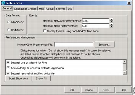
Step 2 Click the up or down arrow buttons next to the Maximum History Entries field to change the entry.
Note Setting the Maximum History Entries value to the high end of the range uses more Cisco Transport Controller (CTC) memory and could impair CTC performance.
Note This task changes the maximum history entries recorded for CTC sessions. It does not affect the maximum number of history entries viewable for a network, node, or card.
Step 4 Return to your originating procedure (NTP).
DLP-A112 Display Alarms and Conditions Using Time Zone
This task changes the time stamp for events to the time zone of the ONS node reporting the alarm. By default, the events time stamp is set to the time zone for the CTC workstation. |
|
Step 1 From the Edit menu, choose Preferences.
The CTC Preferences dialog box appears (Figure 18-1).
Step 2 Check the Display Events Using Each Node’s Time Zone check box. The Apply button is enabled.
Step 4 Return to your originating procedure (NTP).
This task is used to view ONS 15454 events at the card, node, or network level and to refresh the alarm listing so that you can check for new and cleared alarms and conditions. |
|
Step 1 At the card, node, or network view, click the Alarms tab.
This button causes CTC to retrieve a current alarm summary for the card, node, or network. This step is optional because CTC updates the Alarms window automatically as raise/clear messages arrive from the node.
Note Alarms that have been raised during the session will have a check mark in the Alarms window New column. When you click Synchronize, the check mark disappears.
Step 3 Return to your originating procedure (NTP).
Step 1 From the card, node, or network view, click the Conditions tab.
Step 2 Click Retrieve (Figure 18-2).
The Retrieve button requests the current set of fault conditions from the node, card, or network. The window is not updated when events change on the node. You must click Retrieve to see any changes.
Figure 18-2 Node View Conditions Window
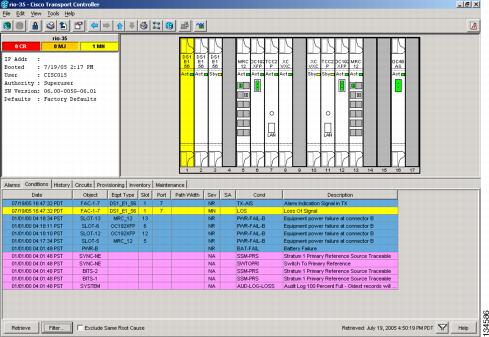
Conditions include all fault conditions raised on the node, whether or not they are reported.
Note Alarms can be unreported when they are filtered out of the display. See the A225 Enable Alarm Filtering for information.
Events that are reported as Major (MJ), Minor (MN), or Critical (CR) severities are alarms. Events that are reported as Not-Alarmed (NA) are conditions. Conditions that are not reported at all are marked Not-Reported (NR) in the Conditions window severity column.
Conditions that have a default severity of Critical (CR), Major (MJ), Minor (MN), or Not-Alarmed (NA) but are not reported due to exclusion or suppression are shown as NR in the Conditions window.
Note For more information about alarm suppression, see the A522 Suppress Alarm Reporting.
Current conditions are shown with the severity chosen in the alarm profile, if used. For more information about alarm profiles, see the A71 Create, Download, and Assign Alarm Severity Profiles.
Note When a port is placed in the Out-of-Service and Management, Maintenance (OOS-MA,MT) service state, it raises an Alarms Suppressed for Maintenance (AS-MT) condition. For information about alarm and condition troubleshooting, refer to the Cisco ONS 15454 Troubleshooting Guide.
Step 3 If you want to apply exclusion rules, check the Exclude Same Root Cause check box at the node or network view, but do not check the Exclude Same Root Cause check box in card view.
An exclusion rule eliminates all lower-level alarms or conditions that originate from the same cause. For example, a fiber break may cause an LOS alarm, an AIS condition, and an SF condition. If you check the Exclude Same Root Cause check box, only the LOS alarm will appear. According to Telcordia, exclusion rules apply to a query of “all conditions from a node.”
Step 4 Return to your originating procedure (NTP).
DLP-A117 Apply Alarm Profiles to Cards and Nodes
This task applies a custom or default alarm profile to cards or nodes. |
|
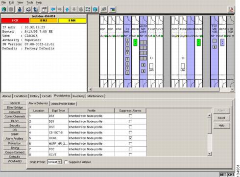
Step 1 In node view, click the Provisioning > Alarm Profiles > Alarm Behavior tabs (Figure 18-3).
Figure 18-3 Node View Alarm Behavior Window
Step 2 To apply profiles to a card:
a. Click a selection from the Profile column for the card.
b. Choose the new profile from the drop-down list.
Step 3 To apply the profile to an entire node:
a. Click the Node Profile drop-down arrow at the bottom of the window (Figure 18-3).
b. Choose the new alarm profile from the drop-down list.
Step 4 To reapply a previous alarm profile after you have applied a new one, select the previous profile and click Apply again.
Step 5 Return to your originating procedure (NTP).
DLP-A121 Enable/Disable Pointer Justification Count Performance Monitoring
Step 1 Enable Intermediate Path Performance Monitoring as specified in A122 Enable/Disable Intermediate Path Performance Monitoring
Step 2 In node view, double-click the card you want to monitor. The card view appears.
See Table 18-1 for a list of line terminating equipment (LTE) cards.
|
|
|---|
Step 3 Click the Provisioning > Line tabs.
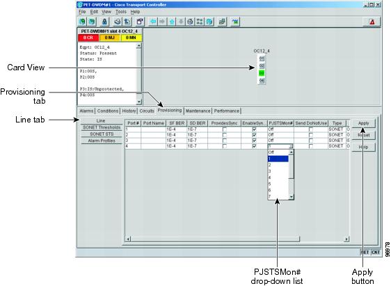
Step 4 From the PJSTSMon# drop-down list, make a selection based on the following rules (Figure 18-4):
Figure 18-4 Enabling or Disabling Pointer Justification Count Parameters
Step 5 In the Service State field, confirm that the port is in the In-Service and Normal (IS-NR) service state.
Step 6 If the port is IS-NR, click Apply. If the port is in the Out-of-Service and Management, Disabled (OOS-MA,DSBLD), Out-of-Service and Management, Maintenance (OOS-MA,MT), or the Out-of-Service and Autonomous, Automatic In-Service (OOS-AU,AINS) service state, choose IS from the Admin State drop-down list and click Apply.
Step 7 Click the Performance tab to view PM parameters. For PM parameter definitions, refer to the “Performance Monitoring” chapter in the Cisco ONS 15454 Reference Manual.
Note The count fields for PPJC and NPJC PM parameters appear white and blank unless pointer justification count performance monitoring is enabled.
Step 8 Return to your originating procedure (NTP).
DLP-A122 Enable/Disable Intermediate Path Performance Monitoring
This task enables or disables intermediate path performance monitoring, which allows you to monitor large amounts of STS traffic through intermediate nodes. |
|
Note The monitored IPPM parameters are STS CV-P, STS ES-P, STS SES-P, STS UAS-P, and STS FC-P. Far-end path monitoring can be performed on the OC3-4 and EC-1 cards. For PM parameter definitions, refer to the “Performance Monitoring” chapter of the Cisco ONS 15454 Reference Manual.
Note An OC-48 IR card used in a BLSR does not support IPPM during a protection switch.
Step 1 In node view, double-click the OC-N card you want to monitor. The card view appears.
See Table 18-1 for a list of OC-N LTE cards.
Step 2 Click the Provisioning > SONET STS tabs (Figure 18-5).
Figure 18-5 SONET STS Tab for Enabling or Disabling IPPM
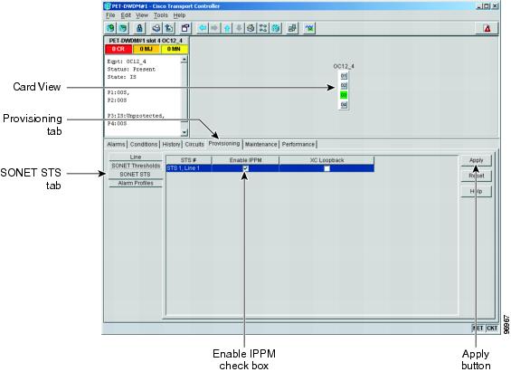
Step 3 Click the check box in the Enable IPPM column and make a selection based on the following rules:
Step 5 Click the Performance tab to view PM parameters. For IPPM parameter definitions, refer to the “Performance Monitoring” chapter of the Cisco ONS 15454 Reference Manual.
Step 6 Return to your originating procedure (NTP).
DLP-A124 Refresh PM Counts at 15-Minute Intervals
This task changes the window view to display PM counts in 15-minute intervals. |
|
Step 1 In node view, double-click the card where you want to view PM counts. The card view appears.
Step 2 Click the Performance tab.
Step 3 Click the 15 min radio button.
Step 4 Click Refresh. Performance monitoring parameters appear in 15-minute intervals synchronized with the time of day.
Step 5 View the Curr column to find PM counts for the current 15-minute interval.
Each monitored performance parameter has corresponding threshold values for the current time period. If the value of the counter exceeds the threshold value for a particular 15-minute interval, a threshold crossing alert (TCA) is raised. The number represents the counter value for each specific performance monitoring parameter.
Step 6 View the Prev- n columns to find PM counts for the previous 15-minute intervals.
Note If a complete 15-minute interval count is not possible, the value appears with a yellow background. An incomplete or incorrect count can be caused by monitoring for less than 15 minutes after the counter started, changing node timing settings, changing the time zone settings, replacing a card, resetting a card, or changing port service states. When the problem is corrected, the subsequent 15-minute interval appears with a white background.
Step 7 Return to your originating procedure (NTP).
DLP-A125 Refresh PM Counts at One-Day Intervals
This task changes the window view to display PM parameters in 1-day intervals. |
|
Step 1 In node view, double-click the card where you want to view PM counts. The card view appears.
Step 2 Click the Performance tab.
Step 3 Click the 1 day radio button.
Step 4 Click Refresh. Performance monitoring appears in 1-day intervals synchronized with the time of day.
Step 5 View the Curr column to find PM counts for the current 1-day interval.
Each monitored performance parameter has corresponding threshold values for the current time period. If the value of the counter exceeds the threshold value for a particular 1-day interval, a threshold crossing alert (TCA) is raised. The number represents the counter value for each specific performance monitoring parameter.
Step 6 View the Prev- n columns to find PM counts for the previous 1-day intervals.
Note If a complete count over a 1-day interval is not possible, the value appears with a yellow background. An incomplete or incorrect count can be caused by monitoring for less than 24 hours after the counter started, changing node timing settings, changing the time zone settings, replacing a card, resetting a card, or changing port service states. When the problem is corrected, the subsequent 1-day interval appears with a white background.
Step 7 Return to your originating procedure (NTP).
DLP-A126 View Near-End PM Counts
This task enables you to view near-end PM counts for the selected card and port. |
|
Step 1 In node view, double-click the card where you want to view PM counts. The card view appears.
Step 2 Click the Performance tab.
Step 3 Click the Near End radio button.
Step 4 Click Refresh. All PM parameters occurring for the selected card on the incoming signal appear. For PM parameter definitions refer to the “Performance Monitoring” chapter of the Cisco ONS 15454 Reference Manual.
Step 5 View the Curr column to find PM counts for the current time interval.
Step 6 View the Prev- n columns to find PM counts for the previous time intervals.
Step 7 Return to your originating procedure (NTP).
DLP-A127 View Far-End PM Counts
This task enables you to view far-end PM parameters for the selected card and port. |
|
Step 1 In node view, double-click the card where you want to view PM counts. The card view appears.
Step 2 Click the Performance tab.
Step 3 Click the Far End radio button.
Step 4 Click Refresh. All PM parameters recorded by the far-end node for the selected card on the outgoing signal appear. For PM parameter definitions refer to the “Performance Monitoring” chapter of the Cisco ONS 15454 Reference Manual.
Step 5 View the Curr column to find PM counts for the current time interval.
Step 6 View the Prev- n columns to find PM counts for the previous time intervals.
Step 7 Return to your originating procedure (NTP).
DLP-A129 Reset Current PM Counts
This task clears the current PM count, but it does not clear the cumulative PM count. This task allows you to see how quickly PM counts rise. |
|
Step 1 In node view, double-click the card where you want to view PM counts. The card view appears.
Step 2 Click the Performance tab.
Note The Baseline button clears the PM counts displayed in the current time interval but does not clear the PM counts on the card. When the current time interval expires or the window view changes, the total number of PM counts on the card and on the window appear in the appropriate column. The baseline values are discarded if you change views to a different window and then return to the Performance window.
Step 4 View the current statistics columns to observe changes to PM counts for the current time interval.
Step 5 Return to your originating procedure (NTP).
This task searches for ONS 15454 circuits at the network, node, or card level. |
|
Step 1 Navigate to the appropriate CTC view:
- To search the entire network, click View > Go to Network View.
- To search for circuits that originate, terminate, or pass through a specific node, click View > Go to Other Node, then choose the node you want to search and click OK.
- To search for circuits that originate, terminate, or pass through a specific card, double-click the card on the shelf graphic in node view to open the card in card view.
Step 2 Click the Circuits tab.
Step 3 If you are in node or card view, choose the scope for the search, Node or Network (All), from the Scope drop-down list located at the bottom right-hand side of the screen.
Step 5 In the Circuit Name Search dialog box, complete the following:
- Find What—Enter the text of the circuit name you want to find.
- Match whole word only—Check this check box to instruct CTC to select circuits only if the entire word matches the text in the Find What field.
- Match case—Check this check box to instruct CTC to select circuits only when the capitalization matches the capitalization entered in the Find What field.
- Direction—Choose the direction for the search. Searches are conducted up or down from the currently selected circuit.
Step 6 Click Find Next. If a match is found, click Find Next again to find the next circuit.
Step 7 Repeat Steps 5 and 6 until you are finished, then click Cancel.
Step 8 Return to your originating procedure (NTP).
DLP-A137 Provision Path Trace on OC-N Ports
This task monitors a path trace on OC-N ports within the circuit path. |
|
The OC-N ports you want to monitor must be on OC-N cards capable of receiving path trace. See Table 19-3. |
|
A264 Provision a J1 Path Trace on Circuit Source and Destination Ports |
|
Step 1 From the View menu, choose Go to Other Node. In the Select Node dialog box, choose the node where path trace was provisioned on the circuit source and destination ports.
Step 3 Choose the STS circuit that has path trace provisioned on the source and destination ports, then click Edit.
Step 4 In the Edit Circuit window, click the Show Detailed Map check box at the bottom of the window. A detailed circuit graphic showing source and destination ports appears.
Step 5 In the detailed circuit map, right-click the circuit OC-N port (the square on the left or right of the source node icon) and choose Edit Path Trace from the shortcut menu.
Note The OC-N port must be on a receive-only card listed in Table 19-3. If not, the Edit Path Trace menu item will not appear.
Step 6 In the Circuit Path Trace window, enable the path trace expected string by choosing Auto or Manual from the Path Trace Mode drop-down list:
- Auto—Uses the first string received from the port at the other path trace end as the current expected string. An alarm is raised when a string that differs from the baseline is received. For OC-N ports, Auto is recommended because Manual mode requires you to trace the circuit in the Edit Circuit window to determine whether the port is the source or destination path.
- Manual—Uses the Current Expected String field as the baseline string. An alarm is raised when a string that differs from the Current Expected String is received.
Step 7 If you set the Path Trace Mode field to Manual, enter the string that the OC-N port should receive in the New Expected String field. To do this, trace the circuit path on the detailed circuit map to determine whether the port is in the circuit source or destination path, then set the New Expected String to the string transmitted by the circuit source or destination. If you set the Path Trace Mode field to Auto, skip this step.
Step 8 Click Apply, then click Close.
Step 9 Return to your originating procedure (NTP).
DLP-A140 Change the Node Name, Date, Time, and Contact Information
This procedure changes basic information such as node name, date, time, and contact information. |
|
Note Changing the date, time, or time zone might invalidate the node’s performance monitoring counters.
Step 1 In node view, click the Provisioning > General tabs.
Step 2 Change any of the following:
Note To see changes to longitude or latitude on the network map, you must go to network view and right-click the specified node, then click Reset Node Position.
See the A25 Set Up Name, Date, Time, and Contact Information for detailed field descriptions.
Step 3 Click Apply. Confirm that the changes appear; if not, repeat the task.
Step 4 Return to your originating procedure (NTP).
DLP-A142 Modify a Static Route
Step 1 In node view, click the Provisioning > Network tabs.
Step 2 Click the Static Routing tab.
Step 3 Click the static route you want to edit.
Step 5 In the Edit Selected Static Route dialog box, enter the following:
See the A65 Create a Static Route for detailed field descriptions.
Step 7 Return to your originating procedure (NTP).
DLP-A143 Delete a Static Route
Step 1 In node view, click the Provisioning > Network > Static Routing tabs.
Step 2 Click the static route you want to delete.
Step 3 Click Delete. A confirmation dialog box appears.
Step 5 Return to your originating procedure (NTP).
This task disables the Open Shortest Path First (OSPF) routing protocol process for an ONS 15454 LAN. |
|
Step 1 In node view, click the Provisioning > Network > OSPF tabs. The OSPF subtab has several options.
Step 2 In the OSPF on LAN area, uncheck the OSPF active on LAN? check box.
Step 4 Return to your originating procedure (NTP).
DLP-A145 Change the Network View Background Color
This task changes the network view background color or the domain view background color (the area displayed when you open a domain). |
|
Note If you modify background colors, the change is stored in your CTC user profile on the computer. The change does not affect other CTC users.
Step 1 From the View menu, choose Go to Network View.
Step 2 If you want to change a domain background, double-click the domain. If not, continue with Step 3.
Step 3 Right-click the network view or domain map area and choose Set Background Color from the shortcut menu.
Step 4 In the Choose Color dialog box, select a background color.
Step 6 Return to your originating procedure (NTP).
This task creates a domain, which is an icon that groups ONS 15454 icons in CTC network view. By default, domains are visible to all CTC sessions that log into the network. |
|
Note Domains created by one user are visible to all users who log into the network.
Note To allow users of any security level to create local domains, that is, domains that are visible on the home CTC session only, superusers can change the CTC.network.LocalDomainCreationAndViewing NE default value to TRUE. A TRUE value means any user can maintain the domain information in his or her Preferences file, meaning domain changes will not affect other CTC sessions. (The default value is FALSE, meaning domain information affects all CTC sessions and only superusers can create a domain or put a node into a domain.) See the A336 Edit Network Element Defaults to change NE default values.
Step 1 From the View menu, choose Go to Network View.
Step 2 Right-click the network map and choose Create New Domain from the shortcut menu.
Step 3 When the domain icon appears on the map, click the map name and type the domain name.
Step 5 Return to your originating procedure (NTP).
Note All domain changes, such as added or removed nodes, are visible to all users who log into the network.
Note To allow users of any security level to create local domains, that is, domains that are visible on the home CTC session only, superusers can change the CTC.network.LocalDomainCreationAndViewing NE default value to TRUE. A TRUE value means any user can maintain the domain information in his or her Preferences file, meaning domain changes will not affect other CTC sessions. (The default value is FALSE, meaning domain information affects all CTC sessions and only superusers can create a domain or put a node into a domain.) See the A336 Edit Network Element Defaults to change NE default values.
Step 1 From the View menu, choose Go to Network View.
Step 2 Locate the domain action you want in Table 18-2 and complete the appropriate steps.
Step 3 Return to your originating procedure (NTP).
DLP-A150 Modify a 1:1 Protection Group
This task modifies a 1:1 protection group for electrical cards (DS-1, DS-3, EC-1, and DS3XM). |
|
Step 1 In node view, click the Provisioning > Protection tabs.
Step 2 In the Protection Groups area, click the 1:1 protection group you want to modify.
Step 3 In the Selected Group area, you can modify the following, as needed:
- Name—As needed, type the changes to the protection group name. The name can have up to 32 alphanumeric characters.
- Revertive—Check this box if you want traffic to revert to the working card after failure conditions stay corrected for the amount of time chosen from the Reversion Time drop-down list. Uncheck if you do not want traffic to revert.
- Reversion time—If the Revertive check box is selected, choose the reversion time from the Reversion time drop-down list. The range is 0.5 to 12.0 minutes. The default is 5.0 minutes. This is the amount of time that will elapse before the traffic reverts to the working card. Traffic can revert when conditions causing the switch are cleared.
Note To convert electrical protection groups, see the A91 Upgrade DS-1 and DS-3 Protect Cards from 1:1 Protection to 1:N Protection.
Step 5 Return to your originating procedure (NTP).
DLP-A152 Modify a 1:N Protection Group
This task modifies a 1:N protection group for DS-1 and DS-3 cards. |
|
Step 1 Verify that the DS-1 or DS-3 cards are installed according to the 1:N specifications in the A72 Create a 1:N Protection Group.
Step 2 In node view, click the Provisioning > Protection tabs.
Step 3 In the Protection Groups area, click the 1:N protection group you want to modify.
Step 4 In the Selected Group area, change any of the following, as needed:
- Name—Type the changes to the protection group name. The name can have up to 32 alphanumeric characters.
- Available Entities—If cards are available, they will appear here. Use the arrow buttons to move them into the Working Cards column.
- Working Entities—Use the arrow buttons to move cards out of the Working Cards column.
- Reversion Time—Choose a reversion time from the drop-down list. The range is 0.5 to 12.0 minutes. The default is 5.0 minutes. This is the amount of time that will elapse before the traffic reverts to the working card. Traffic can revert when conditions causing the switch are cleared.
See the A72 Create a 1:N Protection Group for field descriptions.
Note To convert electrical protection groups, see the A91 Upgrade DS-1 and DS-3 Protect Cards from 1:1 Protection to 1:N Protection.
Step 6 Return to your originating procedure (NTP).
DLP-A154 Modify a 1+1 Protection Group
This task modifies a 1+1 protection group for any optical port (OC-3, OC-12, OC-12 IR, OC-48, OC-48AS, and OC-192). |
|
Step 1 In node view, click the Provisioning > Protection tabs.
Step 2 In the Protection Groups area, click the 1+1 protection group you want to modify.
Step 3 In the Selected Group area, you can modify the following, as needed:
- Name—Type the changes to the protection group name. The name can have up to 32 alphanumeric characters.
- Bidirectional switching—Check or uncheck.
- Revertive—Check this box if you want traffic to revert to the working card after failure conditions stay corrected for the amount of time chosen from the Reversion Time drop-down list. Uncheck if you do not want traffic to revert.
- Reversion time—If the Revertive check box is selected, choose the reversion time from the Reversion time drop-down list. The range is 0.5 to 12.0 minutes. The default is 5.0 minutes. This is the amount of time that will elapse before the traffic reverts to the working card. Traffic can revert when conditions causing the switch are cleared.
See the A73 Create a 1+1 Protection Group for field descriptions.
Step 5 Return to your originating procedure (NTP).
DLP-A155 Delete a Protection Group
This task deletes a 1:1, 1:N, 1+1, or Y-cable protection group. |
|
Step 1 In node view, click the Provisioning > Protection tabs.
Step 2 In the Protection Groups area, click the protection group you want to delete.
Step 4 Click Yes in the Delete Protection Group dialog box.
Step 5 Return to your originating procedure (NTP).
DLP-A156 Delete a Section DCC Termination
This task deletes a SONET Section DCC termination on the ONS 15454. |
|
Step 1 Click the Provisioning > Comm Channel > S DCC tabs.
Step 2 Click the SDCC termination to be deleted and click Delete. The Delete SDCC Termination dialog box appears.
Step 3 Click Yes in the confirmation dialog box.
Step 4 Return to your originating procedure (NTP).
DLP-A157 Change the Node Timing Source
This task changes the SONET timing source for the ONS 15454. |
|
 The following procedure might be service affecting and should be performed during a scheduled maintenance window.
Step 1 In node view, click the Provisioning > Timing tabs.
Step 2 In the General Timing section, change any of the following information:
Note Because mixed timing can cause timing loops, Cisco does not recommend using the Mixed Timing option. Use this mode with care.
See the A69 Set Up SONET External or Line Timing for field descriptions.
Step 3 In the BITS Facilities section, you can change the following information:
Note The BITS Facilities section sets the parameters for your BITS1 and BITS2 timing references. Many of these settings are determined by the timing source manufacturer. If equipment is timed through BITS Out, you can set timing parameters to meet the requirements of the equipment.
Step 4 In the Reference Lists area, you can change the following information:
Note Reference lists define up to three timing references for the node and up to six BITS Out references. BITS Out references define the timing references used by equipment that can be attached to the node’s BITS Out pins on the backplane. If you attach equipment to BITS Out pins, you normally attach it to a node with Line mode because equipment near the external timing reference can be directly wired to the reference.
Step 6 Return to your originating procedure (NTP).
DLP-A158 Change User Password and Security Level on a Single Node
This task changes settings for an existing user at one node. |
|
Step 1 In node view, click the Provisioning > Security > Users tabs.
Step 2 Click the user whose settings you want to modify, then click Change.
Step 3 In the Change User dialog box, you can:
See the A30 Create Users and Assign Security for field descriptions.
Note User settings that you changed during this task will not appear until that user logs off and logs back in.
Step 5 Return to your originating procedure (NTP).
DLP-A159 Delete a User from a Single Node
Note You cannot delete a user who is currently logged in. To log out a user, you can complete the A315 Log Out a User on a Single Node, or you can choose the “Logout before delete” option in the Delete User dialog box.
Note CTC will allow you to delete other Superusers if one Superuser remains. For example, you can delete the CISCO15 user if you have created another Superuser. Use this option with caution.
Step 1 In node view, click the Provisioning > Security > Users tabs.
Step 2 Choose the user you want to delete.
Step 4 In the Delete User dialog box, verify that the user name displayed is the one you want to delete.
Step 6 Return to your originating procedure (NTP).
DLP-A160 Change User Password and Security Level on Multiple Nodes
This task changes settings for an existing user at multiple nodes. |
|
Note You must add the same user name and password to each node the user will access.
Step 1 From the View menu, choose Go to Network View. Verify that you can access all the nodes where you want to add users.
Step 2 Click the Provisioning > Security > Users tabs. Highlight the user’s name whose settings you want to change.
Step 3 Click Change. The Change User dialog box appears.
Step 4 In the Change User dialog box, you can:
See the A75 Create a New User on Multiple Nodes for field descriptions.
Step 5 In the Select Applicable Nodes area, uncheck any nodes where you do not want to change the user’s settings (all network nodes are selected by default).
Step 6 Click OK. A Change Results confirmation dialog box appears.
Step 7 Click OK to acknowledge the changes.
Step 8 Return to your originating procedure (NTP).
DLP-A161 Delete a User from Multiple Nodes
Note You cannot delete a user who is currently logged in. To log out a user, you can complete the A316 Log Out a User on Multiple Nodes, or you can choose the “Logout before delete” option in the Delete User dialog box.
Note CTC will allow you to delete other Superusers if one Superuser remains. For example, you can delete the CISCO15 user if you have created another Superuser. Use this option with caution.
Step 1 From the View menu, choose Go to Network View.
Step 2 Click the Provisioning > Security tabs. Highlight the name of the user you want to delete.
Step 3 Click Delete. The Delete User dialog box appears.
Step 4 In the Select Applicable Nodes area, uncheck any nodes where you do not want to delete this user.
Step 5 Click OK. A User Deletion Results confirmation dialog box appears.
Step 6 Click OK to acknowledge the changes.
Step 7 Return to your originating procedure (NTP).
DLP-A163 Delete SNMP Trap Destinations
This task deletes Simple Network Management Protocol (SNMP) trap destinations on an ONS 15454. |
|
Step 1 In node view, click the Provisioning > SNMP tabs.
Step 2 In the Trap Destinations area, click the trap you want to delete.
Step 3 Click Delete. A confirmation dialog box appears.
Step 5 Return to your originating procedure (NTP).
DLP-A165 Change Line and Threshold Settings for a DS1-14 or DS1N-14 Card
This task changes the line and threshold settings for a DS1-14 or DS1N-14 card. |
|
Note For the default values and domains of user-provisionable card settings, refer to the “Network Element Defaults” appendix in the Cisco ONS 15454 Reference Manual.
Step 1 In node view, double-click the DS1-14 or DS1N-14 card where you want to change the line or threshold settings.
Step 2 Click the Provisioning tab.
Step 3 Depending on the setting you need to modify, click the Line, Line Thresholds, Elect Path Thresholds, or SONET Thresholds tab.
Note See Chapter 8, “Manage Alarms” for information about the Alarm Profiles tab.
Note If you want to modify a threshold setting, it might be necessary to click on the available directional, type, and interval (15 Min, 1 Day) radio buttons and then click Refresh. This will display the desired threshold setting.
Step 4 Modify the settings found under these subtabs by clicking in the field you want to modify. In some fields you can choose an option from a drop-down list; in others you can type a value.
Step 6 Repeat Steps 3 through 5 for each subtab that has parameters you want to provision.
For definitions of the line settings, see Table 18-3. For definitions of the line threshold settings, see Table 18-4. For definitions of the electrical path threshold settings, see Table 18-5. For definitions of the SONET threshold settings, see Table 18-6.
Table 18-3 describes the values on the Provisioning > Line tabs.
|
|
|
|
|---|---|---|
User-defined, up to 32 alphanumeric/special characters. Blank by default. See the A314 Assign a Name to a Port. |
||
Defines the distance (in feet) from the backplane connection to the next termination point. |
||
Sets the port administrative service state unless network conditions prevent the change. |
Note CTC will not allow you to change a port service state from IS-NR to OOS-MA,DSBLD. You must first change a port to the OOS-MA,MT service state before putting it in the OOS-MA,DSBLD service state. |
|
(Display only) Identifies the autonomously generated state that gives the overall condition of the port. Service states appear in the format: Primary State-Primary State Qualifier, Secondary State. |
|
|
Table 18-4 describes the values on the Provisioning > Line Thresholds tabs.
Table 18-5 describes the values on the Provisioning > Elect Path Thresholds tabs.
Table 18-6 describes the values on the Provisioning > SONET Thresholds tabs for the DS-1 cards.
Note The threshold value appears after the circuit is created.
Step 7 Return to your originating procedure (NTP).
DLP-A166 Change Line and Threshold Settings for a DS3-12 or DS3N-12 Card
This task changes the line and threshold settings for a DS3-12 or DS3N-12 card. |
|
Note For the default values and domains of user-provisionable card settings, refer to the “Network Element Defaults” appendix in the Cisco ONS 15454 Reference Manual.
Step 1 Double-click the DS3-12 or DS3N-12 card where you want to change the line or threshold settings.
Step 2 Click the Provisioning tab.
Step 3 Depending on the setting you need to modify, click the Line, Line Thresholds, Elect Path Thresholds, or SONET Thresholds tab.
Note See Chapter 8, “Manage Alarms” for information about the Alarm Profiles tab.
Note If you want to modify a threshold setting, it might be necessary to click on the available directional, type, and interval (15 Min, 1 Day) radio buttons and then click Refresh. This will display the desired threshold setting.
Step 4 Modify the settings found under these subtabs by clicking in the field you want to modify. In some fields you can choose an option from a drop-down list; in others you can type a value.
Step 6 Repeat Steps 3 through 5 for each subtab that has parameters you want to provision.
For definitions of the line settings, see Table 18-7. For definitions of the line threshold settings, see Table 18-8. For definitions of the Elect Path Threshold settings, see Table 18-9. For definitions of the SONET threshold settings, see Table 18-10.
Table 18-7 describes the values on the Provisioning > Line tabs.
|
|
|
|
|---|---|---|
User-defined, up to 32 alphanumeric/special characters. Blank by default. See the A314 Assign a Name to a Port. |
||
Defines the distance (in feet) from backplane connection to the next termination point. |
||
Sets the port administrative service state unless network conditions prevent the change. |
Note CTC will not allow you to change a port service state from IS-NR to OOS-MA,DSBLD. You must first change a port to the OOS-MA,MT service state before putting it in the OOS-MA,DSBLD service state. |
|
(Display only) Identifies the autonomously generated state that gives the overall condition of the port. Service states appear in the format: Primary State-Primary State Qualifier, Secondary State. |
|
|
Duration of the valid input signal, in hh.mm format, after which the card becomes in service (IS) automatically 0 to 48 hours, 15-minute increments. |
Table 18-8 describes the values on the Provisioning > Line Thresholds tabs.
Table 18-9 describes the values on the Provisioning > Elect Path Thresholds tabs.
Table 18-10 describes the values on the Provisioning > SONET Thresholds tabs.
Note The threshold value appears after the circuit is created.
Step 7 Return to your originating procedure (NTP).
DLP-A167 Change Line and Threshold Settings for a DS3E-12 or DS3N-12E Card
This task changes the line and threshold settings for a DS3E-12 or DS3N-12E (DS3E) card. |
|
Note For the default values and domains of user-provisionable card settings, refer to the “Network Element Defaults” appendix in the Cisco ONS 15454 Reference Manual.
Note If the DS3E is installed in an ONS 15454 slot that is provisioned for a DS-3 card, the DS3E enhanced performance monitoring parameters are unavailable. If this occurs, remove the DS3E from the ONS 15454, delete the DS-3 card in CTC using the A191 Delete a Card, and provision the slot for the DS3E using the A330 Preprovision a Card Slot.
Step 1 Double-click the DS3E-12 or DS3N-12E card where you want to change the line or threshold settings.
Step 2 Click the Provisioning tab.
Step 3 Depending on the setting you need to modify, click the Line, Line Thresholds, Elect Path Thresholds, or SONET Thresholds tab.
Note See Chapter 8, “Manage Alarms” for information about the Alarm Profiles tab.
Note If you want to modify a threshold setting, it might be necessary to click on the available directional, type, and interval (15 Min, 1 Day) radio buttons and then click Refresh. This will display the desired threshold setting.
Step 4 Modify the settings found under these subtabs by clicking in the field you want to modify. In some fields you can choose an option from a drop-down list; in others you can type a value.
Step 6 Repeat Steps 3 through 5 for each subtab that has a parameter you want to provision.
For definitions of the line settings, see Table 18-11 . For definitions of the line threshold settings, see Table 18-12. For definitions of the electrical path threshold settings, see Table 18-13. For definitions of the SONET threshold settings, see Table 18-14.
Table 18-11 describes the values on the Provisioning > Line tabs.
|
|
|
|
|---|---|---|
User-defined, up to 32 alphanumeric/special characters. Blank by default. See the A314 Assign a Name to a Port. |
||
Defines the distance (in feet) from backplane connection to the next termination point. |
||
Sets the port administrative service state unless network conditions prevent the change. |
Note CTC will not allow you to change a port service state from IS-NR to OOS-MA,DSBLD. You must first change a port to the OOS-MA,MT service state before putting it in the OOS-MA,DSBLD service state. |
|
(Display only) Identifies the autonomously generated state that gives the overall condition of the port. Service states appear in the format: Primary State-Primary State Qualifier, Secondary State. |
Note CTC will not allow you to change a port service state from IS-NR to OOS-MA,DSBLD. You must first change a port to the OOS-MA,MT service state before putting it in the OOS-MA,DSBLD service state. |
|
Table 18-12 describes the values on the Provisioning > Line Thresholds tabs.
Table 18-13 describes the values on the Provisioning > Elect Path Thresholds tabs.
Table 18-14 describes the values on the Provisioning > SONET Thresholds tabs.
Note The threshold value appears after the circuit is created.
Step 7 Return to your originating procedure (NTP).
DLP-A168 Change Line and Threshold Settings for the DS3XM-6 Card
This task changes the line and threshold settings for the DS3XM-6 card. |
|
Note The DS3XM-6 (transmux) card can accept up to six channelized DS-3 signals and convert each signal to 28 VT1.5 signals. Conversely, the card can take 28 T-1s and multiplex them into a channeled C-bit or M13 framed DS-3.
Note For the default values and domains of user-provisionable card settings, refer to the “Network Element Defaults” appendix in the Cisco ONS 15454 Reference Manual.
Step 1 In node view, double-click the DS3XM-6 card where you want to change the line or threshold settings.
Step 2 Click the Provisioning tab.
Step 3 Depending on the setting you need to modify, click the Line, Line Thresholds, Elect Path Thresholds, or SONET Thresholds tab.
Note See Chapter 8, “Manage Alarms” for information about the Alarm Profiles tab.
Note If you want to modify a threshold setting, it might be necessary to click on the available directional, type, and interval (15 Min, 1 Day) radio buttons and then click Refresh. This will display the desired threshold setting.
Step 4 Modify the settings found under these subtabs by clicking in the field you want to modify. In some fields you can choose an option from a drop-down list; in others you can type a value.
Step 6 Repeat Steps 3 through 5 for each subtab that has parameters you want to provision.
For definitions of the line settings, see Table 18-15 . For definitions of the line threshold settings, see Table 18-16. For definitions of the electrical path threshold settings, see Table 18-17. For definitions of the SONET threshold settings, see Table 18-18.
Table 18-15 describes the values on the Provisioning > Line tabs for the DS3XM-6 cards.
|
|
|
|
|---|---|---|
User-defined, up to 32 alphanumeric/ special characters. Blank by default. See the A314 Assign a Name to a Port. |
||
Defines the distance (in feet) from backplane connection to the next termination point. |
||
Sets the port administrative service state unless network conditions prevent the change. |
Note CTC will not allow you to change a port service state from IS-NR to OOS-MA,DSBLD. You must first change a port to the OOS-MA,MT service state before putting it in the OOS-MA,DSBLD service state. |
|
(Display only) Identifies the autonomously generated state that gives the overall condition of the port. Service states appear in the format: Primary State-Primary State Qualifier, Secondary State. |
|
|
Table 18-16 describes the values on the Provisioning > Line Thresholds tabs for DS3XM-6 cards.
Table 18-17 describes the values on the Provisioning > Elect Path Thresholds tabs for the DS3XM-6 cards.
Table 18-18 describes the values on the Provisioning > SONET Thresholds tabs for the DS3XM-6 cards.
Note The threshold value appears after the circuit is created.
Step 7 Return to your originating procedure (NTP).
DLP-A169 Change Line and Threshold Settings for the EC1-12 Card
This task changes the line and threshold settings for the EC1-12 (EC-1) card. |
|
Note For the default values and domains of user-provisionable card settings, refer to the “Network Element Defaults” appendix in the Cisco ONS 15454 Reference Manual.
Step 1 In node view, double-click the EC-1 card where you want to change the line or threshold settings.
Step 2 Click the Provisioning tab.
Step 3 Depending on the setting you need to modify, click the Line or SONET Thresholds tabs.
Note See Chapter 8, “Manage Alarms” for information about the Alarm Profiles tab.
Note The STS subtab is used to provision intermediate path performance monitoring (IPPM). To provision IPPM, circuits must be provisioned on the EC1-12 card. For circuit creation procedures, go to Chapter6, “Create Circuits and VT Tunnels” To provision IPPM, go to the A121 Enable/Disable Pointer Justification Count Performance Monitoring.
Note If you want to modify a threshold setting, it might be necessary to click on the available directional, type, and interval (15 Min, 1 Day) radio buttons and then click Refresh. This will display the desired threshold setting.
Step 4 Modify the settings found under these subtabs by clicking in the field you want to modify. In some fields you can choose an option from a drop-down list; in others you can type a value.
Step 6 Repeat Steps 3 through 5 for each subtab that has parameters you want to provision.
Table 18-19 describes the values on the Line tab for the EC1-12 card. For definitions of the SONET threshold settings, see Table 18-20.
|
|
|
|
|---|---|---|
User-defined, up to 32 alphanumeric/ special characters. Blank by default. See the A314 Assign a Name to a Port. |
||
Sets the STS that will be used for pointer justification; if set to zero, no STS is used. |
||
Defines the distance (in feet) from backplane to next termination point. |
||
For early EC1-12 card versions, equalization can be turned off if the line length is short or the environment is extremely cold; Rx Equalization should normally be set to On. |
||
Sets the port administrative service state unless network conditions prevent the change. |
Note CTC will not allow you to change a port service state from IS-NR to OOS-MA,DSBLD. You must first change a port to the OOS-MA,MT service state before putting it in the OOS-MA,DSBLD service state. |
|
(Display only) Identifies the autonomously generated state that gives the overall condition of the port. Service states appear in the format: Primary State-Primary State Qualifier, Secondary State. |
|
|
Table 18-20 lists the values on the SONET Thresholds tab for EC1-12 cards.
|
|
|
|
|---|---|---|
Step 7 Return to your originating procedure (NTP).
DLP-A171 Change Threshold Settings for OC-N Cards
Note For the default values and domains of user-provisionable card settings, refer to the “Network Element Defaults” appendix in the Cisco ONS 15454 Reference Manual.
Step 1 In node view, double-click the OC-N card where you want to change the threshold settings.
Step 2 Click the Provisioning > SONET Thresholds tabs.
Note If you want to modify a threshold setting, it might be necessary to click on the available directional, type, and interval (15 Min, 1 Day) radio buttons and then click Refresh. This will display the desired threshold setting.
Step 3 Modify the settings described in Table 18-21 by clicking in the field you want to modify and typing in the desired value.
Step 5 Return to your originating procedure (NTP).
DLP-A172 Change an Optical Port to SDH
This task provisions a port on an OC-N card for SDH. You must put the port in the OOS,MT administrative service state before changing the port to SDH. |
|
Step 1 In node view, double-click the OC-N card where you want to provision a port for SDH.
Step 2 Click the Provisioning > Line tabs.
Step 3 In the Type field for the desired port, choose SDH.
Note Before you change the port type to SDH, ensure the following: the EnableSyncMsg and SendDoNotUse fields are unchecked, the card is not part of a BLSR or 1+1 protection group, the card is not part of an orderwire channel, and the card is not a SONET data communications channel/generic communications channel (DCC/GCC) termination point.
Step 5 If the card is a multiport OC-N card, for example a four-port OC-3, eight-port OC-3, four-port OC-12, or MRC-12, you can repeat Steps 3 and 4 for any other ports on that card.
Step 6 Return to your originating procedure (NTP).
DLP-A176 Convert DS1-14 Cards From 1:1 to 1:N Protection
This task converts DS1-14 cards in a 1:1 protection scheme to 1:N protection. A 1:N protection group can protect a maximum of five working cards. |
|
Note This procedure assumes DS1-14 cards are installed in Slots 1 through 6 and/or Slots 12 through 17. The DS1-14 cards in Slots 3 and 15, which are the protection slots, will be replaced with DS1N-14 cards.
Step 1 In node view, click the Maintenance > Protection tabs.
Step 2 Click the protection group that contains Slot 3 or Slot 15 (where you will install the DS1N-14 card).
Step 3 Make sure the slot you are upgrading is not carrying working traffic. In the Selected Group list, the protect slot must say Protect/Standby, not Protect/Active. If the protect slot status is Protect/Active, switch traffic to the working card:
a. Under Selected Group, click the protect card.
b. Next to Switch Commands, click Switch.
The working slot should change to Working/Active and the protect slot should change to Protect/Standby. If they do not change, do not continue. Troubleshoot the working card and slot to determine why the card cannot carry working traffic.
Step 4 Repeat Steps 1 through 3 for each protection group that you need to convert.
Step 5 Click the Alarms tab to verify that no standing alarms exist for any of the DS1-14 cards that you are converting. If alarms exist and you have difficulty clearing them, contact your next level of support.
Step 6 Click the Provisioning > Protection tabs.
Step 7 Click the 1:1 protection group that contains the cards that you will move into the new protection group.
Step 9 When the confirmation dialog box appears, click Yes.
Note Deleting the 1:1 protection group does not disrupt service. However, no protection bandwidth exists for the working circuits until you complete the 1:N protection procedure. Therefore, complete this procedure as quickly as possible.
Step 10 If needed, repeat Steps 7 to 9 for other DS-1 1:1 protection groups that you want to include in a 1:N group.
Step 11 Physically remove the DS1-14 card from Slot 3 or Slot 15. This raises an improper removal alarm (IMPROPRMVL).
Step 12 In node view, right-click the slot that held the removed card and select Delete from the shortcut menu. Wait for the card to disappear from node view.
Step 13 Physically insert a DS1N-14 card into the same slot.
Step 14 Verify that the card boots up properly.
Step 15 Click the Inventory tab and verify that the new card appears as a DS1N-14.
Step 16 Click the Provisioning > Protection tabs.
Step 18 Type a name for the protection group in the Name field (optional).
Step 19 From the Type drop-down list, choose 1:N (card).
Step 20 From the Protect Card drop-down list, choose the DS1N-14 card. Verify that the correct DS1N-14 card appears in the Protect Card field.
Step 21 In the Available Cards list, highlight the cards that you want in the protection group. Click the arrow (>>) tab to move the cards to the Working Cards list.
Step 22 If necessary, set a new reversion time in the Reversion time drop-down list.
Note 1:N protection groups are always revertive.
Step 23 Click OK. The protection group appears in the Protection Groups list on the Protection subtab.
Step 24 Return to your originating procedure (NTP).
DLP-A177 Convert DS3-12 Cards From 1:1 to 1:N Protection
This task converts DS3-12 cards in 1:1 protection to 1:N protection. A 1:N protection group can protect a maximum of five working cards. |
|
Note This procedure assumes that DS3-12 cards are installed in Slots 1 to 6 and/or Slots 12 to 17. The DS3-12 cards in Slots 3 or 15, which are the protection slots, will be replaced with DS3N-12 cards. The ONS 15454 must run CTC Release 2.0 or later. The procedure also requires at least one DS3N-12 card and a protection group with DS3-12 cards.
Step 1 In node view, click the Maintenance > Protection tabs.
Step 2 Click the protection group containing Slot 3 or Slot 15 (where you will install the DS3N-12 card).
Step 3 Make sure the slot that you are upgrading is not carrying working traffic. In the Selected Group list, the protect slot must say Protect/Standby, and not Protect/Active. If the protect slot status is Protect/Active, switch traffic to the working card:
a. Under Selected Group, click the protect card.
b. Next to Switch Commands, click Switch.
The working slot should change to Working/Active and the protect slot should change to Protect/Standby. If they fail to change, do not continue. Troubleshoot the working card and slot to determine why the card cannot carry working traffic.
Step 4 Repeat Steps 2 and 3 for each protection group that you need to convert.
Step 5 Click the Alarms tab to verify that no standing alarms exist for any of the DS3-12 cards you are converting. If alarms exist and you have difficulty clearing them, contact your next level of support.
Step 6 Click the Provisioning > Protection tabs.
Step 7 Click the 1:1 protection group that contains the cards that you will move into the new protection group.
Step 9 When the confirmation dialog box appears, click Yes.
Note Deleting the 1:1 protection groups will not disrupt service. However, no protection bandwidth exists for the working circuits until the 1:N protection procedure is completed. Therefore, complete this procedure as soon as possible.
Step 10 If you are deleting more than one DS-3 1:1 protection group, repeat Steps 7 through 9 for each group that you want to include in a 1:N group.
Step 11 Physically remove the protect DS3-12 card from Slot 3 or Slot 15. This raises an improper removal alarm (IMPROPRMVL).
Step 12 In node view, right-click the slot that held the removed card and choose Delete from the shortcut menu. Wait for the card to disappear from the node view.
Step 13 Physically insert a DS3N-12 card into the same slot.
Step 14 Verify that the card boots up properly.
Step 15 Click the Inventory tab and verify that the new card appears as a DS3N-12 card.
Step 16 Click the Provisioning > Protection tabs.
Step 18 Type a name for the protection group in the Name field (optional).
Step 19 Click Type and choose 1:N (card) from the drop-down list.
Step 20 Verify that the DS3N-12 card appears in the Protect Card field.
Step 21 In the Available Cards list, highlight the cards that you want in the protection group. Click the arrow (>>) tab to move the cards to the Working Cards list.
The protection group should appear in the Protection Groups list on the Protection subtab.
Step 23 Return to your originating procedure (NTP).
DLP-A178 Convert DS3-12E Cards From 1:1 to 1:N Protection
This task converts DS3-12E cards in 1:1 protection to 1:N protection. A 1:N protection group can protect a maximum of five working cards. |
|
Note This task assumes that DS3-12E cards are installed in Slots 1 to 6 and/or Slots 12 to 17. The DS3-12E cards in Slots 3 or 15, which are the protection slots, will be replaced with DS3N-12E cards. The procedure requires at least one DS3N-12E card and a protection group with DS3-12E cards.
Step 1 In node view, click the Maintenance > Protection tabs.
Step 2 Click the protection group containing Slot 3 or Slot 15 (where you will install the DS3N-12E card).
Step 3 Make sure the slot you are upgrading is not carrying working traffic. In the Selected Group list, the protect slot must say Protect/Standby, and not Protect/Active. If the protect slot status is Protect/Active, switch traffic to the working card:
a. Under Selected Group, click the protect card.
b. Next to Switch Commands, click Switch.
The working slot should change to Working/Active and the protect slot should change to Protect/Standby. If they fail to change, do not continue. Troubleshoot the working card and slot to determine why the card cannot carry working traffic.
Step 4 Repeat Steps 2 and 3 for each protection group that you need to convert.
Step 5 Click the Alarms tab to verify that no standing alarms exist for any of the DS3-12E cards you are converting. If alarms exist and you have difficulty clearing them, contact your next level of support.
Step 6 Click the Provisioning > Protection tab.
Step 7 Click the 1:1 protection group that contains the cards that you will move into the new protection group.
Step 9 When the confirmation dialog box appears, click Yes.
Note Deleting the 1:1 protection groups will not disrupt service. However, no protection bandwidth exists for the working circuits until the 1:N protection procedure is completed. Do not delay when completing this procedure.
Step 10 If you are deleting more than one DS-3 1:1 protection group, repeat Steps 7 through 9 for each group that you want to include in a 1:N group.
Step 11 Physically remove the protect DS3-12E card from Slot 3 or Slot 15. This raises an improper removal alarm (IMPROPRMVL).
Step 12 In node view, right-click the slot that held the removed card and choose Delete from the shortcut menu. Wait for the card to disappear from the node view.
Step 13 Physically insert a DS3N-12E card into the same slot.
Step 14 Verify that the card boots up properly.
Step 15 Click the Inventory tab and verify that the new card appears as a DS3N-12E.
Step 16 Click the Provisioning > Protection tabs.
Step 18 Type a name for the protection group in the Name field (optional).
Step 19 Click Type and choose 1:N (card) from the drop-down list.
Step 20 Verify that the DS3N-12E card appears in the Protect Card field.
Step 21 In the Available Cards list, highlight the cards that you want in the protection group. Click the arrow (>>) tab to move the cards to the Working Cards list.
The protection group should appear in the Protection Groups list on the Protection subtab.
Step 23 Return to your originating procedure (NTP).
DLP-A189 Verify that a 1+1 Working Slot is Active
This task verifies that a working slot in a 1+1 protection scheme is active (and that the protect slot is in standby). |
|
Step 1 In node view, click the Maintenance > Protection tabs.
Step 2 In the Selected Group area, verify that the working slot/port is shown as Working/Active. If so, this task is complete.
Step 3 If the working slot says Working/Standby, perform a Manual switch on the working slot:
a. In the Selected Group area, choose the Protect/Active slot.
b. In the Switch Commands field, choose Manual.
c. Click Yes in the confirmation dialog box.
Step 4 Verify that the working slot is carrying traffic (Working/Active).
Note If the slot is not active, look for conditions or alarms that might be preventing the card from carrying working traffic. Refer to the Cisco ONS 15454 Troubleshooting Guide for alarm descriptions and instructions.
Step 5 When the working slot is carrying traffic, clear the Manual switch:
a. In the Switch Commands field, choose Clear.
b. Click Yes in the confirmation dialog box.
Step 6 Verify that the working slot does not revert to Standby, which might indicate a problem on the working span.
Step 7 Return to your originating procedure (NTP).
Always use an electrostatic discharge (ESD) wristband when working with a powered ONS 15454. For detailed instructions on how to wear the ESD wristband, refer to the
Cisco ONS Electrostatic Discharge (ESD) and Grounding Guide.
Note UBIC-V EIAs can only be installed on shelf assembly 15454-SA-HD. 15454-SA-HD shelf assemblies are differentiated from other shelf assemblies by the blue hexagon symbol, which indicates the available high-density slots, found under Slots 1 through 3 and 15 through 17.
Note UBIC-V or UBIC-H EIAs are required when using high-density (48-port DS-3 and 12-port DS3XM) electrical cards.
Step 1 Locate the correct UBIC-V EIA for the side you want to install and remove the UBIC EIA-V from the packaging.
Step 2 Verify that none of the pins on the UBIC EIA are bent.
Step 3 If present, remove the yellow connector protectors.
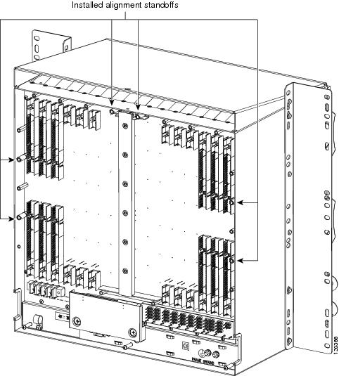
Step 4 If screws are present in the alignment standoff holes, use a Phillips screwdriver to remove them.
Step 5 Use a flathead screwdriver or 5/16-inch deep socket wrench to tighten the standoffs at 8 to 10 inch pound-force (lb-in) (9.2 to 11.5 centimeter kilogram-force[kgf-cm]). Figure 18-6 shows the alignment standoffs installed on the shelf.
Figure 18-6 Installed Alignment Standoffs
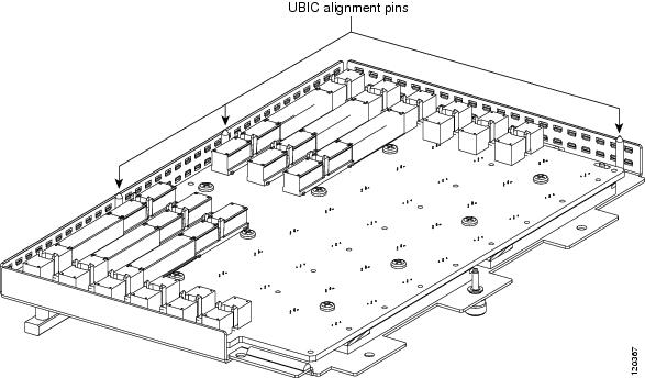
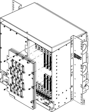
Step 6 Line up the alignment pins on the UBIC EIA with the alignment standoffs on the shelf and push the UBIC EIA with consistent pressure until the pins and standoffs fit together firmly (Figure 18-7).
Figure 18-7 UBIC-V Alignment Pins
 Do not force the UBIC-V EIA onto the shelf if you feel strong resistance.
Step 7 Locate the three jack screws on the UBIC-V (Figure 18-8). Starting with any jack screw, tighten the thumb screw a few turns and move to the next one, turning each thumb screw a few turns at a time until all three screws are hand tight (Figure 18-9).
Tightening the jack screws unevenly could cause damage to the UBIC-V connectors.
Figure 18-8 UBIC-V EIA Screw Locations
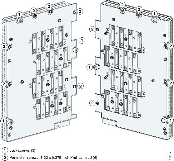
Figure 18-9 UBIC-V EIA Jack Screw
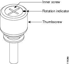
Step 8 Use a Phillips screwdriver to install the six perimeter screws and bracket screws (P/N 48-0422-01) at 8 to 10 lb-inch (9.2 to 11.5kgf-cm) to secure the cover panel to the backplane (Figure 18-8). Install the alarm and timing panel cover and insert and tighten the last perimeter screw.
Figure 18-10 shows a UBIC-V EIA installation.
Figure 18-10 Installing the UBIC-V EIA
Step 9 Return to your originating procedure (NTP).
Step 1 On the shelf graphic in CTC, right-click the card that you want to remove and choose Delete Card.
You cannot delete a card if any of the following conditions apply:
- The card is a TCC2/TCC2P card. To replace a TCC2/TCC2P card, refer to the Cisco ONS 15454 Troubleshooting Guide.
- The card is part of a protection group; see the A155 Delete a Protection Group.
- The card has circuits; see the A278 Modify and Delete Overhead Circuits and Server Trails and the A333 Delete Circuits.
- The card is part of a BLSR; see the A240 Remove a BLSR Node.
- The card is being used for timing; see the A157 Change the Node Timing Source.
- The card has a DCC/GCC termination; see the A292 Modify or Delete Communications Channel Terminations and Provisionable Patchcords.
Note If you delete a card in CTC but do not remove it from the shelf, it will reboot and reappear in CTC.
Step 2 Return to your originating procedure (NTP).
DLP-A194 Clear a BLSR Force Ring Switch
Step 1 From the View menu, choose Go to Network View.
Step 2 Click the Provisioning > BLSR tabs.
Step 4 To clear a Force switch on the west line:
a. Right-click the BLSR west port where you want to clear the protection switch and choose Set West Protection Operation. Ports with a Force switch applied are marked with an F.
b. In the Set West Protection Operation dialog box, choose CLEAR from the pull-down menu. Click OK.
c. In the Confirm BLSR Operation dialog box, click Yes.
Step 5 To clear a Force switch on the east line:
a. Right-click the BLSR east port where you want to clear the protection switch and choose Set East Protection Operation. Ports with a Force switch applied are marked with an F.
b. In the Set East Protection Operation dialog box, choose CLEAR from the pull-down menu. Click OK.
c. In the Confirm BLSR Operation dialog box, click Yes.
On the BLSR network graphic, a green and a purple span line connects each node. This is the normal display for BLSRs when protection operations are not invoked.
Step 6 From the File menu, choose Close.
Step 7 Return to your originating procedure (NTP).
DLP-A195 Verify Timing in a Reduced Ring
This task verifies timing in the ring where you removed a node. |
|
Step 1 In node view, click the Provisioning > Timing tabs.
Step 2 Observe the Timing Mode field to see the type of timing (Line, External, Mixed) that has been set for that node.
Step 3 Scroll down to the Reference Lists and observe the NE Reference fields to see the timing references provisioned for that node.
Step 4 If the removed node was the only BITS timing source, perform the following:
a. Contact your synchronization coordinator or appropriate personnel before continuing with this procedure.
b. Look for another node on the ring that can be used as a BITS source and set that node’s Timing Mode to External. Choose that node as the primary timing source for all other nodes in the ring. See the A157 Change the Node Timing Source.
c. If no node in the reduced ring can be used as a BITS source, choose one node to be your internal timing source. Set that node’s Timing Mode to External, set BITS-1 and BITS-2 BITS In State to OOS, and set the NE Reference to Internal. Then, choose line timing for all other nodes in the ring. This forces the first node to be their primary timing source. (See the A157 Change the Node Timing Source.)
Note This type of timing conforms to Stratum 3 requirements and is not considered optimal.
Step 5 If the removed node was not the only BITS timing source, provision the adjacent nodes to line timing using SONET links (east and west) as timing sources, traceable to the node with external BITS timing. See the A28 Set Up Timing.
Step 6 Return to your originating procedure (NTP).
DLP-A196 Delete a BLSR from a Single Node
This task deletes a BLSR from a node after you remove the node from the BLSR. |
|
Step 1 In node view, display the node that was removed from the BLSR:
- If the node that was removed is connected to the same LAN as your computer, from the File menu, choose Add Node, then enter the node name or IP address.
- If the node that was removed is not connected to the same LAN as your computer, you must connect to the node using a direct connection. See Chapter 3, “Connect the PC and Log into the GUI” for procedures.
Step 2 Click the Provisioning > BLSR tabs.
Step 3 Highlight the ring and click Delete.
Step 4 In the Suggestion dialog box, click OK.
Step 5 In the confirmation message, confirm that this is the ring you want to delete. If so, click Yes.
Step 6 Return to your originating procedure (NTP).
DLP-A197 Initiate a Path Protection Force Switch
This task switches all circuits on a path protection span to another span. |
|
The Force Switch Away command overrides normal protective switching mechanisms. Applying this command incorrectly can cause traffic outages.
Traffic is not protected during a Force protection switch.
Step 1 From the View menu, choose Go to Network View.
Step 2 Right-click the span where you want to switch path protection traffic away. Choose Circuits from the shortcut menu.
Step 3 In the Circuits on Span dialog box, choose FORCE SWITCH AWAY. Click Apply.
Step 4 In the Confirm Path Protection Switch dialog box, click Yes.
Step 5 In the Protection Switch Result dialog box, click OK.
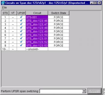
In the Circuits on Span window, the Switch State for all circuits is FORCE. Figure 18-11 shows an example.
Figure 18-11 Circuits on Span Dialog Box with a Force Switch
Note A Force switch request on a span or card causes CTC to raise a FORCED-REQ condition. The condition clears when you clear the Force switch.
Step 6 Return to your originating procedure (NTP).
DLP-A198 Clear a Path Protection Force Switch
Step 1 From the View menu at the node view, choose Go to Network View.
Step 2 Right-click the span where you want to clear the switch. Choose Circuits from the shortcut menu.
Step 3 In the Circuits on Span dialog box, choose CLEAR to remove the Force switch. Click Apply.
Step 4 In the Confirm Path Protection Switch dialog box, click Yes.
Step 5 In the Protection Switch Result dialog box, click OK.
In the Circuits on Span window, the Switch State for all path protection circuits is CLEAR.
Step 6 Return to your originating procedure (NTP).
 Feedback