Table Of Contents
Using the Network Configuration Toolset
Opening the Network Configuration Toolset
Editing and Deleting Access Lines
ASE Data Collection Parameters
Setting ASE Data Collection Parameters for an Access Line and Collect Data
Setting ASE Communication Parameters
Selecting a Monitored Link Interface
Selecting a Monitored Link Interface for ASEs with Multiple Link Interface Capabilities
Configuring IP Transport Settings
Configuring Class of Service Policing Thresholds
Configuring the Committed Access Rate
Configuring Upper Layer Analysis
Configuring Link Layer Settings
Configuring Frame Relay Settings
Configuring Physical Layer Settings
Configuring T1 Interface Parameters
Configuring DS3 Interface Parameters
Updating the ASE Software Version
Configuring Frame Relay and ATM Circuits
Configuring VPI/VCIs and Paths
Connecting End-to-End Circuits
Configuring ATM Class of Service
Editing and Deleting Frame Relay or ATM Circuits
Adding an IP Circuit Automatically
Defining the HDLC Circuit Connection
Printing a Network Configuration Report
Network Configuration
Use the Network Configuration Toolset to set up specific wide area network (WAN) elements for the active domain. This defines the network in the Cisco WAPMS network performance database.
To configure a network in Cisco WAPMS, you must know the logical layout of network elements (your networks, sites, access lines, and circuits), the IP addresses of the ASEs on your network, and the access line properties (physical, link, and upper layer analysis settings) for ASEs. Both enterprise users and WAN service providers take the same basic actions to configure networks.
Once initial configuration is complete, you can begin to effectively monitor and analyze WAN performance. All network configuration data is stored in the PAM's short-term database within the domain to which you are currently connected. Use Network Configuration on an ongoing basis to add, modify, or delete any network element so the database accurately reflects changes in the WAN.
Topics in this chapter include:
•
"Using the Network Configuration Toolset"—using the Network Configuration Toolset
•
•
•
•
•
•
Using the Network Configuration Toolset
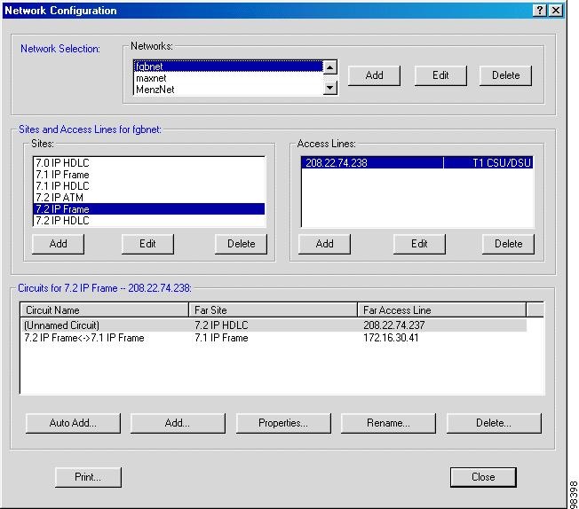
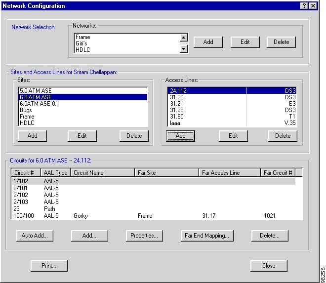
You initiate all configuration tasks for networks, sites, access lines, ASEs, and circuits from the Network Configuration window. Figure 3-1 shows a configuration for an IP Transport ASE.
To access and use Network Configuration, your user ID must have permission granted by your PAM administrator. For a list of permissions configurable from the PAM, see the "User Permissions" section.
Opening the Network Configuration Toolset
Step 1
Step 2
See the "Connecting to a Domain" section.
Step 3
The Network Configuration window, shown in Figure 3-1, appears.
When this option is unavailable, your user ID does not have permission to use Network Configuration.
Figure 3-1 Network Configuration Window
The Network Configuration window has three panes:
•
•
•
To close the Network Configuration window, click Close. The window immediately closes. There is no Cancel button. To cancel actions when configuring network elements, you must do so when you are prompted to confirm the action.
Note
Configuring Networks
In the Network Selection pane of the Network Configuration window, you can add, edit, or delete networks.
•
•
•
Once you configure a network, you can add sites.
Configuring Sites
In the Sites and Access Lines pane of the Network Configuration window, you can add, edit, or delete sites. Typically, sites are identified by location or function.
•
•
•
Once you configure a site you can set up access lines for that site.
Configuring Access Lines
When configuring access lines, you can configure the physical, link, and upper layer analysis settings of the ASE residing on that access line. Typically, access lines are identified by network facility name (usually the circuit ID). Options vary by ASE type. Configuring an access line involves:
•
•
•
•
Ordinarily, ASEs will have already been physically installed on your network before you configure them in the network performance database. Under certain circumstances, however, you may want to configure an access line before its ASE is installed. Use the Network Configuration tool to configure a skeleton network and then complete configuration after the ASE is installed.
For partner devices with multiple link interfaces, you must specify which link interface to monitor when adding an associated access line. (See the "Selecting a Monitored Link Interface" section.)
Adding an Access Line
For every access line you configure for a currently uninstalled ASE, proceed through Step 3 of the following procedure. After the ASE has been installed and configured, resume configuration at Step 4.
Step 1
Step 2
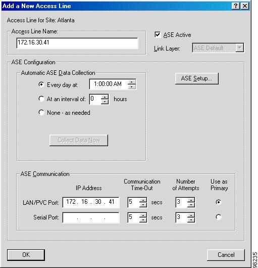
The Add a New Access Line window appears.
Figure 3-2 Add/Edit an Access Line Window
Step 3
Note
Step 4
The Link Layer is ASE Default, which automatically detects the link layer type from the ASE. Link layer values are ATM, Frame Relay, and HDLC. When no ASE is connected to the network, you can change the link layer by clearing ASE Active.
Note
Step 5
For details, see the "ASE Data Collection Parameters" section and the "ASE Communication Parameters" section.
Step 6
When Cisco WAPMS makes contact with the ASE, the ASE Configuration window appears. For details, see the "Configuring ASEs" section.
When an ASE is contacted but no access line speed (or a line speed of zero) is detected, the Access Line Speed window appears.
Step 7
Contact your service provider for access line speed information.
Note
There may be a slight delay as Cisco WAPMS attempts to contact the ASE based on the Number of Attempts setting in the Add/Edit an Access Line window. The Auto-identifying status window appears with an updated message. If attempts to contact the ASE exceed the number specified, the Auto-identifying window notifies you contact with the ASE has failed.
Step 8
a.
b.
Step 9
If it fails, contact your vendor's technical support.
Step 10
Editing and Deleting Access Lines
You can also make changes to a configured access line and delete access lines.
Editing an Access Line
Select the network and site related to the access line. Select the access line to edit, then click Edit. Change the ASE properties as needed.
Deleting an Access Line
Select the network and site related to the access line. Select the access line to delete, then click Delete. This deletes the access line and all DLCIs (Frame Relay), VPI/VCIs (ATM), or IP circuits related to it. It does not delete the network and site to which the access line belonged.
ASE Data Collection Parameters
You configure ASE data collection parameters as part of configuring an access line. You can set Cisco WAPMS to retrieve the contents of the ASE's local buffer at preset intervals or only on request. For more information about adding an access line, see the "Adding an Access Line" section.
ASEs collect and store network statistics continuously in a local buffer for approximately two days. To archive these statistics for more than two days, you must retrieve them by collecting data from the ASE. Data collection copies these network statistics to the short-term database on the PAM. For data collection to occur, the PAM must be running continuously.
Caution
Setting ASE Data Collection Parameters for an Access Line and Collect Data
Step 1
a.
b.
c.
Figure 3-3 Automatic ASE Data Collection Pane
You have three options:
–
–
–
Step 2
ASE Communication Parameters
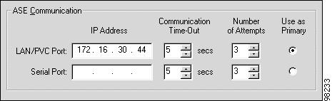
You set ASE communication parameters as part of configuring an access line. These parameters determine how Cisco WAPMS and the ASE communicate. For more information on adding an access line, see the "Configuring Access Lines" section.
Setting ASE Communication Parameters
Step 1
•
•
Step 2
This address must match the one locally configured on the ASE.
Figure 3-4 ASE Communication Pane - Add a New Access Line Window
Step 3
Step 4
Step 5
LAN/PVC Port is the default.
Selecting a Monitored Link Interface
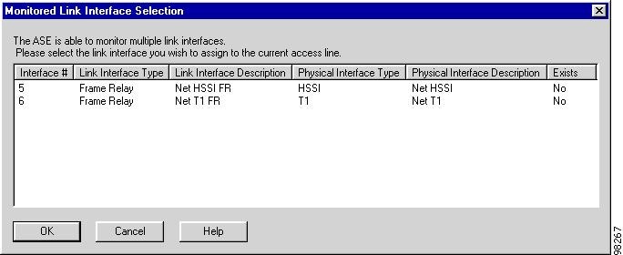
For ASEs with multiple link interface capabilities, you must specify which link interface to monitor when adding an associated access line. For ASEs with only one link interface, Cisco WAPMS monitors that interface by default when you add an associated access line.
Selecting a Monitored Link Interface for ASEs with Multiple Link Interface Capabilities
Step 1
The Add a New Access Line window appears.
Step 2
The Monitored Link Interface Selection window, shown in Figure 3-5, appears.
Figure 3-5 Monitored Link Interface Selection Window
Step 3
Step 4
Configuring ASEs
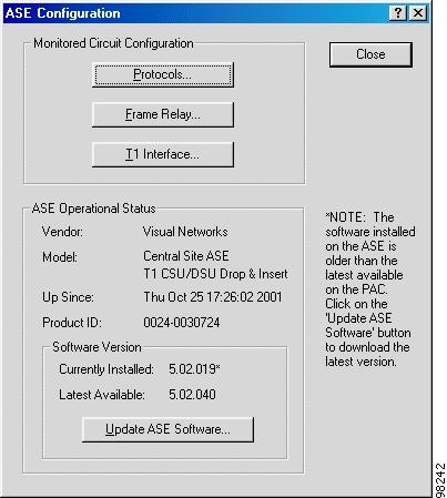
As you configure an access line, you specify settings for the ASE on that access line. From the ASE Configuration window (Figure 3-6), you can configure the upper, link, and physical layer settings on the ASE, and update ASE software.
Figure 3-6 ASE Configuration Window - Frame Relay ASE
The upper, link, and physical layer options vary by the WAN link layer and the ASE type of the access line. Use the buttons in the Monitored Circuit Configuration pane to configure the layer settings on the ASE:
•
•
•
In the ASE Operational Status pane you can view the ASE vendor, product ID, software version installed, and other important information about the ASE. You can also update the software version on the ASE.
The Software Version pane displays Multi-Protocol or IP Transport and the software version number for Cisco WAPMS ASEs only.
The Update ASE Software button allows you to do the following:
•
•
•
Note
Configuring an ASE
Step 1
Step 2
•
•
Step 3
The ASE Configuration window appears (see Figure 3-6). Options in the window vary based on the ASE type. For details, see the following sections:
•
•
•
•
Once you configure a Frame Relay/HDLC or ATM ASE, you can apply these settings to other ASEs on your network. (You cannot, however, apply templates to IP Transport ASEs.) Use the Templates tool in the PAM Manager application to import those settings into a template and then apply the template to other ASEs. For more information, see Chapter 4, "Managing ASEs Using PAM Manager," in the Cisco WAN Access Performance Management System System Administration Guide, 2.0.
Configuring IP Transport Settings
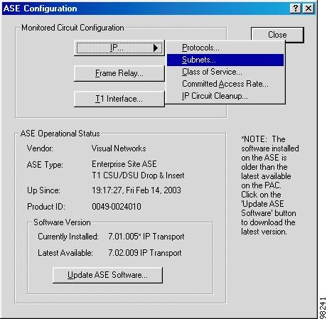
When you are configuring an IP Transport ASE, the top (upper layer) button in the ASE Configuration window is labeled IP (see Figure 3-7). Click the IP button to view a menu of IP configuration options:
•
•
•
•
•
Figure 3-7 ASE Configuration Window for an IP Transport ASE
Configuring Subnets
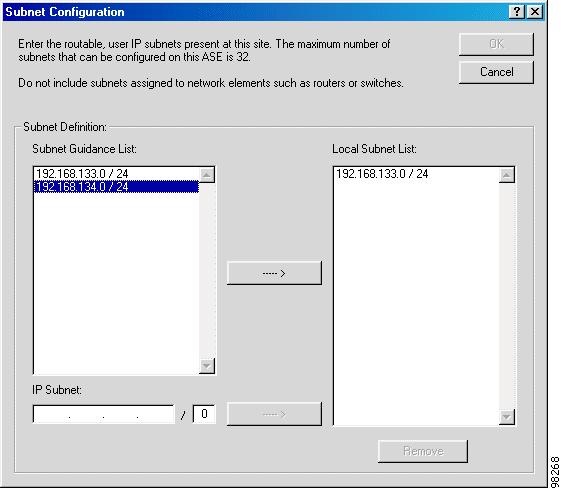
When configuring an IP Transport ASE, you must specify the IP subnets used at an ASE's location. You can specify up to 32 subnets in the ASE's Local Subnet list in the Subnet Configuration window (see Figure 3-8). This list of subnets identifies traffic originating from and going to the ASE's location.
Figure 3-8 Subnet Configuration Window
In the Subnet Configuration window, the Subnet Guidance list is a collection of local IP address subnets observed by the ASE while monitoring traffic flow at its location. This list stores up to 16 IP addresses, with the most recently observed subnet at the top of the list. When a subnet is not observed after 24 hours, it is removed from the list. When the list is full, the oldest subnet is removed. The ASE updates the Subnet Guidance list continuously; it is cleared when the ASE is rebooted.
Subnets contain an IP address (32 bits) and a classless interdomain routing (CIDR) type mask count of 8 bits. The first time the ASE observes a new IP address, it auto-detects a mask of 32. If it observes a second nearby address, the mask is widened to 24. After this point, the mask is widened one bit at a time as needed, based on observations.
Note
When manually entering IP address subnets, you can set the size of the CIDR mask. For more information, see the "CIDR (classless interdomain routing)" entry in the Glossary.
Note
Configuring the ASE's Local Subnet List
Step 1
The Subnet Configuration window appears (see Figure 3-8).
Step 2
•
•
Step 3
Step 4
Step 5
Configuring Class of Service Policing Thresholds
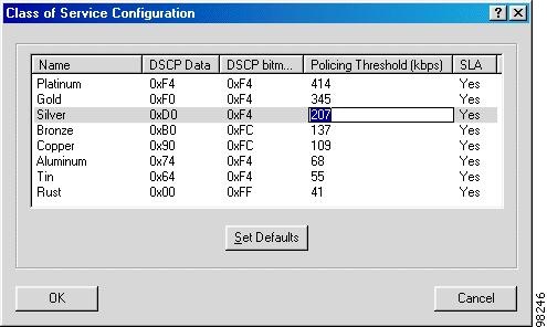
In the Class of Service Configuration window, you can modify policing thresholds for class of service settings (up to eight classes) for the IP Transport ASE and view—but not modify—other class settings, including the name, 8-bit DSCP (Differentiated Services Code Point) data and bitmask, and Service Level Agreement (SLA) settings. You can also re-apply the default settings configured in PAM Administration.
Caution
Policing threshold, in kilobits per second, is the upper limit for the specified class, usually set by the service provider in the service level agreement. Service usage exceeding this mark would not be guaranteed to the same degree as service up to this mark.
DSCP data and bitmask determine the class of service for a particular packet in hexadecimal notation. Bitmask indicates what bits are relevant to the class of service. Data indicates the values of the relevant bits. You cannot change these settings in this window.
In the Network Configuration tool, when you add or edit IP Transport ASEs, CoS settings are downloaded from that ASE using TFTP. When no classes are defined, the default settings defined for that domain are sent to that ASE. Changes you make at the PAC overwrite any settings applied at the ASE's administrative interface.
Modifying the Policing Threshold for Class of Service
Step 1
The Class of Service Configuration window, shown in Figure 3-9, appears.
Figure 3-9 Class of Service Configuration Window
Step 2
•
•
Note
Step 3
A warning states ASE statistics will be reset.
Step 4
Configuring the Committed Access Rate
You can view and configure the Committed Access Rate (CAR) for the access line monitored by an IP Transport ASE. The CAR indicates through a channel-wide mechanism how much traffic is allocated to IP traffic. When CAR is set to 0, then calculations will be based on line speed.
Modifying the Committed Access Rate
Step 1
Step 2
Configuring Upper Layer Analysis
Upper layer analysis options in the ASE Configuration window vary by ASE type (see Table 3-1).
Protocols
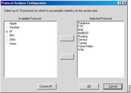
Use the Protocols button in the ASE Configuration window (Figure 3-7) to configure upper layer analysis settings for Multi-Protocol Frame Relay, HDLC, or ATM ASEs. (For IP Transport ASEs, access the option from the IP button.) Protocol options vary by ASE model and software version installed on the ASE. Any protocol you configure can be in the network or application layers, or it can be a custom-defined IP protocol. Valid custom IP ports range from 1 to 65535.
For a detailed listing and description of supported protocols, see "Supported Network and Internet Protocols."
Figure 3-10 Protocol Analysis Configuration Window
When configuring protocols keep in mind the following:
•
•
•
•
•
•
•
•
•
Configuring Protocols
Step 1
Step 2
The Protocol Analysis Configuration window appears. (Figure 3-10 shows a Frame Relay ASE.)
Step 3
Step 4
When your network uses more than one component from any single aggregate, you can filter specific protocols in Traffic Capture. Troubleshooting, Planning and Reporting, and Performance Monitoring will keep the protocols aggregated.
Caution
Step 5
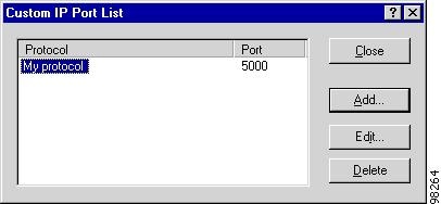
The Custom IP Port List window, shown in Figure 3-11, appears. Any custom IP protocols configured are listed. For custom protocols with ranges defined, the port range appears.
Figure 3-11 Custom IP Port List Window
Step 6
•
•
•
When you edit the port number or delete a protocol for which the ASE is currently collecting statistics, a warning appears stating statistics on the ASE will be reset.
Caution
Step 7
To move custom protocols to the Selected Protocols list, in the Available Protocols list, click IP to expand the list, select the custom protocols from the list, then click the arrow button.
Step 8
Note
Application Layer
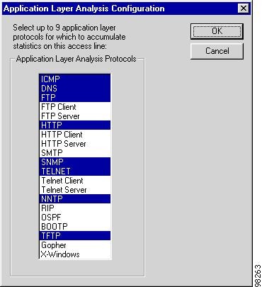
For HDLC Multi-Protocol ASEs, use the Application Layer button for upper layer analysis on the ASE Configuration window to configure up to nine application layer protocols.
Configuring Application Layer Protocols
Step 1
The Application Layer Analysis Configuration window, shown in Figure 3-12, appears.
Some protocols are listed more than once. For example, HTTP is listed as HTTP, HTTP Client, and HTTP Server. Client protocols count traffic to and from clients at the monitored site (Web browsers, in the case of HTTP Client). Server protocols count traffic to and from servers at the monitored site (Web servers, in the case of HTTP Server). Protocols not designated as client or server (such as HTTP) count client and server traffic together, without distinguishing between the two. Protocols not listed are aggregated in the Other category.
Figure 3-12 Application Layer Analysis Configuration Window
Step 2
Configuring Link Layer Settings
The link layer button on the ASE Configuration window varies according to whether the data link type of the ASE is Frame Relay, HDLC, or ATM.
Configuring Frame Relay Settings
Cisco WAPMS provides default values for Frame Relay settings. WAN service providers do not typically deviate from the default settings. However, it is recommended that before accepting the defaults, you confirm with your provider their settings match the defaults.
When you change the committed information rate (CIR) value on a shared ASE (an ASE using the management traffic consolidation feature), an "Unable to contact ASE" message is issued while you momentarily lose connectivity. Connectivity is restored after a few moments.
Note
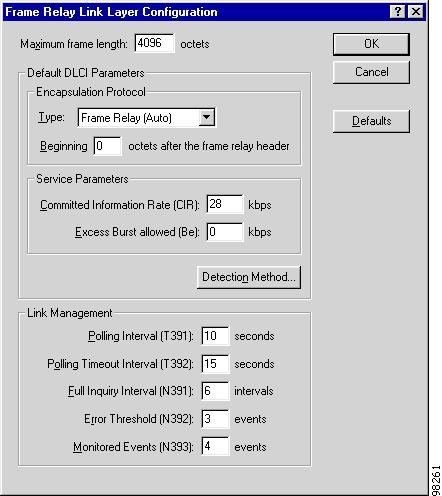
Figure 3-13 Frame Relay Link Layer Configuration Window
Configuring Frame Relay Parameters
Step 1
The Frame Relay Link Layer Configuration window, shown in Figure 3-13, appears.
For Frame Relay-based IP Transport ASEs, the Service Parameters pane and Detection Method button are not displayed.
Step 2
Step 3
Consult your service provider to verify correct values.
Step 4
Table 3-2 Frame Relay Link Layer Configuration Window Options
Maximum Frame Length
Maximum length of a transmitted frame on the access line. The valid range is 262 to 65535 octets. The default and the most commonly used value is 4096.
Encapsulation Protocol Type
Default protocol encapsulation method for this link. This option enables the ASE to collect protocol-based statistics. This setting is applied to all DLCIs discovered by the ASE. For information on encapsulation protocols, see "Encapsulation Protocols."
Encapsulation Protocol Beginning x octets after the Frame Relay header
Default number of octets beyond the Frame Relay header where the encapsulation protocol header begins. It is applied to all DLCIs discovered by the ASE.
Committed Information Rate (CIR)
Maximum data rate at which the router/FRAD can send data without risk of dropped packets. This setting is applied to all DLCIs discovered by the ASE.
Excess Burst Allowed (Be)
Maximum allowable excess burst rate beyond the CIR; can be determined by router or port. Calculated as port speed - CIR. This setting is applied to all DLCIs discovered by the ASE.
Detection Method
Method the ASE uses to add DLCIs. The ASE can detect DLCIs according to:
•
•
•
Note
Polling Interval
Time between status inquiries sent from the Frame Relay switch. This setting must match the configuration of your router/switch. The default setting should work for most configurations. (T391 is the name of this variable in the Frame Relay Specification, ANSI T1.617 Annex D.)
Polling Timeout Interval
Length of time the DTE waits for a status message from the DCE before sending another status inquiry. This setting must match the configuration of your router/switch. The default setting should work for most configurations. (T392 is the name of this variable in the Frame Relay specification, ANSI T1.617 Annex D.)
Full Inquiry Interval
Number of polling intervals that will trigger a full status inquiry. For example, when the polling interval is six, the DTE initiates a full status inquiry every 60 seconds. This setting must match the configuration of your router/switch. The default setting should work for most configurations. (N391 is the name of this variable in the Frame Relay specification, ANSI T1.617 Annex D.)
Error Threshold
Maximum number of status inquiries that go unanswered before the link is declared down. This setting must match the configuration of your router/switch. The default setting should work for most configurations. (This selection works with Monitored Events.) (N392 is the name of this variable in the Frame Relay specification, ANSI T1.617 Annex D.)
Monitored Events
Number of status inquiries actually monitored, in contrast to those unanswered. For example, when the Error Threshold is three and Monitored Events is set to four, a sequence of four consecutive inquiries are monitored. If three of those four inquiries are unanswered, the link is declared down. This setting must match the configuration of your router/switch. The default setting should work for most configurations. (N393 is the name of this variable in the Frame Relay specification, ANSI T1.617 Annex D.)
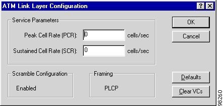
Configuring ATM Settings
Cisco WAPMS provides default values for ATM settings, except Peak Cell Rate (PCR) and Sustained Cell Rate (SCR). WAN service providers do not typically deviate from the default settings. However, it is recommended that before accepting the defaults, you confirm with your provider their settings match the defaults.
Note
Step 1
The ATM Link Configuration window, shown in Figure 3-14, appears.
Figure 3-14 ATM Link Layer Configuration Window
Step 2
Consult your service provider for correct PCR and SCR values.
Step 3
Table 3-3 ATM Link Layer Configuration Window Options
Peak Cell Rate (PCR)
Default value for the maximum rate at which cells can be transmitted over any VPI/VCI configured for this ASE. This value is applied to all VPI/VCIs that are auto-discovered by the ASE after this value is set. VPI/VCIs already configured are unaffected unless you select Clear VCs. Individual VPI/VCIs can have greater values. See Table 3-8.
Valid values depend on framing type. For HEC, the range is 0 to 104268. For Physical Layer Convergence Protocol (PLCP), the range is 0 to 96000.
Sustained Cell Rate (SCR)
Default value for the maximum average rate at which cells can be sent over any VPI/VCI configured for this ASE. This value is applied to all VPI/VCIs that are auto-discovered by the ASE after this value is set. VPI/VCIs already configured are unaffected unless you select Clear VCs. Individual VPI/VCIs can have greater values. See Table 3-8. Valid values are limited to line speed.
Scramble Configuration
Indicates whether payload data is scrambled at transmission and unscrambled when received. Displayed values are Enabled or Disabled. This parameter is set at the ASE during installation.
Framing
Method of cell synchronization. Displayed values are HEC or PLCP. This parameter is set at the ASE during installation.
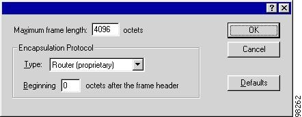
Configuring HDLC Settings
Cisco WAPMS provides default values for HDLC settings. WAN service providers do not typically deviate from the default settings. Before accepting the defaults, however, confirm with your provider their settings match.
Step 1
The HDLC Configuration window, shown in Figure 3-15, appears.
Figure 3-15 HDLC Configuration Window
Step 2
Consult your service provider for correct SCR and PCR values.
Step 3
Table 3-4 HDLC Configuration Window Options
Maximum Frame Length
Maximum length of a transmitted frame on the access line. The valid range is 262 to 65535 octets. The default and the most commonly used value is 4096.
Encapsulation Protocol Type
Protocol encapsulation method for this link. This option enables the system to collect protocol-based statistics. For information on encapsulation protocols, see "Encapsulation Protocols."
Encapsulation Protocol Beginning x octets after the Frame Header
Number of octets beyond the frame header where the encapsulation protocol header begins.
Configuring Physical Layer Settings
For T1 Frame Relay and DS3 ATM ASEs, you can configure the access line's physical layer settings from the ASE Configuration window (Figure 3-6). Options vary depending on whether the ASE resides on a T1, DS3, or E3 access line. This option is not available for partner devices. You do not configure physical layer settings for ASEs using E3, HSSI, DDS, V.35, X.21, EIA-530, RS-449, and RS-232 physical layers, because the ASE automatically obtains physical layer information from the access line.
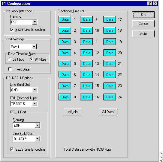
Configuring T1 Interface Parameters
Cisco WAPMS provides default values for the T1 interface parameters. WAN service providers do not typically deviate from the default settings. However, it is recommended that before accepting the defaults, you confirm with your provider their settings match the defaults.
When a T1 passive probe ASE resides on the access line, the ASE can typically obtain physical layer parameters automatically from the line itself.
Note
Step 1
The T1 Configuration window, shown in Figure 3-16, appears.
Figure 3-16 T1 Configuration Window
Step 2
•
•
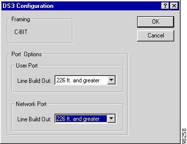
Configuring DS3 Interface Parameters
Cisco WAPMS provides default values for the DS3 interface parameters. WAN service providers do not typically deviate from the default settings. However, it is recommended that before accepting the defaults, you confirm with your provider their settings match the defaults.
Step 1
The DS3 Configuration window, shown in Figure 3-17, appears.
Figure 3-17 DS3 Configuration Window
Step 2
Updating ASE Software
For individual ASEs, you can update the ASE software version using the ASE Configuration window. The ASE Software Version pane displays the software currently installed on the ASE and the latest version available from the PAC. To update software for a group of ASEs, see the "Updating Multiple ASEs" section.
Note
In the ASE Configuration window, a note informs you when the versions differ and suggests the appropriate action. You may want to update the ASE software version under the following circumstances:
•
•
•
When updating ASE software versions, keep in mind the following:
Note
•
•
•
Caution
Updating the ASE Software Version
Step 1
A confirmation window appears. (When the Update ASE Software option is unavailable, either no ASE software is available on the PAC or your user ID does not have permission to update ASE software. Contact your PAM administrator.)
Step 2
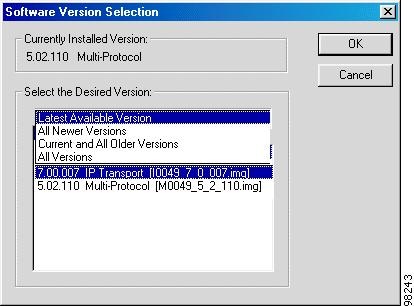
The Software Version Selection window, shown in Figure 3-18, appears. You will have another opportunity to cancel updating without affecting the ASE.
Step 3
•
•
•
•
Figure 3-18 Software Version Selection Window
Step 4
Step 5
•
•
Caution
Step 6
Configuring Circuits
You can configure the circuits used in your network from the Network Configuration window. Options in the window vary by the type of ASE you select:
•
•
•
Configuring Frame Relay and ATM Circuits
You configure Frame Relay PVC or ATM VC circuits or paths in the Circuits pane of the Network Configuration window (see Figure 3-19). The Circuits box shows the circuit number, name, AAL type (for ATM), far site, far access line, and far circuit number.
A Frame Relay PVC is identified by a data link connection identifier (DLCI) at each end. An ATM virtual circuit (VC) is identified by a virtual path identifier/virtual circuit identifier (VPI/VCI) at each end. ATM ASEs and some partner devices give you the option of configuring the virtual path (VP, also called a path), rather than specifying the VPI and VCI for the circuit.
Note
Configuring Frame Relay or ATM circuits involves:
•
•
•
Frame Relay and ATM can be mixed in a single circuit, where one circuit end point is a DLCI and the other is a VPI/VCI. However, you cannot mix an HDLC circuit with a Frame Relay or an ATM circuit.
Figure 3-19 Network Configuration Window—Circuit Configuration (ATM Shown)
The name of the selected ASE and access line appear above the lower pane in the Network Configuration window. In the Circuits column, the configured circuits for the selected ASE and access line are listed. To scroll through the list of circuit end points, select any end point, then enter the first few characters of its name. The configured path (available for ATM ASEs and some partner devices) and the configured VPI/VCI circuit and AAL type appear in the AAL Type column.
Adding Circuit End Points
Automatically Adding DLCIs or VCs to an Access Line
Step 1
Step 2
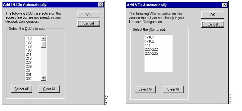
Depending on your circuit type, the Add DLCIs Automatically or Add VCs Automatically window, both shown in Figure 3-20, appears.
Figure 3-20 Add DLCIs and Add VCs Automatically Windows
The window shows DLCI or VC circuit end points the ASE has detected on your network, but have not yet been configured in the network performance database.
For 6.0 Visual ATM ASEs, this window shows VPI/VCIs that are AAL-1, AAL-2 or AAL-5 and Path. For ATM partner devices, the window displays all VPI/VCIs for supported AAL types, or Other. "Other" indicates a VC with a protocol type other than AAL-1, AAL-2, or AAL-5 has been detected on the line. Up to 600 AAL-5 circuits are automatically detected. Any AAL-5 circuits detected beyond this limit are also labeled Other.
Step 3
Manually Adding a DLCI or VC Circuit (or Range of Circuits)
Step 1
Step 2
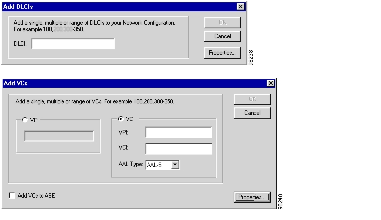
Depending on the type of ASE (ATM or Frame Relay), the Add DLCIs or Add VCs window, both shown in Figure 3-21, appears.
Figure 3-21 Add DLCIs and Add VCs Windows
Step 3
For 6.0 Visual ATM ASE circuits and supported partner ASE circuits, use the Add VC window to specify the VC as a virtual path (VP or Path), or as a VCC—a VPI and associated VCI.
Step 4
The default is AAL-5.
Step 5
Step 6
(See Table 3-7 for DLCI parameter definitions; see Table 3-8 for VC parameter definitions.)
Figure 3-22 DLCI and VC Configuration Windows
For ATM circuits, check Use Default to use the default SCR and PCR values set when you configured the ATM link layer parameters for the ASE. (See the "Configuring ATM Settings" section.)
Configuring DLCIs
You can customize DLCI configurations by changing the default settings. WAN service providers do not typically deviate from the default settings. However, it is recommended that before accepting the defaults, you confirm with your provider that their settings match the defaults.
Customizing DLCIs
Step 1
Step 2
Step 3
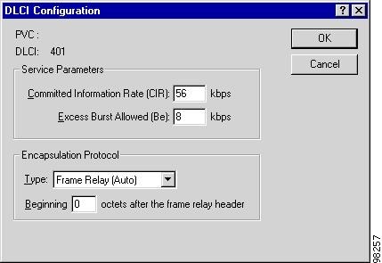
The DLCI Configuration window, shown in Figure 3-23, appears.
Figure 3-23 DLCI Configuration - Properties Window
Step 4
Table 3-7 DLCI Configuration Window Options
Committed Information Rate (CIR)
Maximum data rate at which the router/FRAD can send data without risk of dropped packets.
Excess Burst Allowed (Be)
Maximum allowable excess burst rate beyond the CIR; can be determined by router or port. Calculated as port speed - CIR.
Encapsulation Protocol Type
Protocol encapsulation method for this DLCI. This option enables the system to collect protocol-based statistics. (For information on encapsulation protocols, see "Encapsulation Protocols.")
Encapsulation Protocol Beginning x octets after the Frame Relay Header
Number of octets beyond the frame header where the encapsulation protocol header begins.
Configuring VPI/VCIs and Paths
You can customize VPI/VCI and Virtual Path (VP or Path) configurations by changing the default settings. WAN service providers do not typically deviate from the default settings. However, it is recommended that before accepting the defaults, you confirm with your provider their settings match the defaults.
Customizing a VPI/VCI or Path
Step 1
Step 2
Step 3
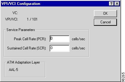
The VPI/VCI Configuration window, shown in Figure 3-24, appears. The window options vary depending upon whether you selected a VPI/VCI or VP.
Figure 3-24 VPI/VCI Configuration Window
Step 4
(See Table 3-8.) The PCR and SCR settings affect how data appears for different views in the Troubleshooting Toolset.
Connecting End-to-End Circuits
You can connect Frame Relay-to-Frame Relay circuits, ATM-to-ATM circuits, and IP-to-IP circuits. You also can connect mixed circuits (Frame Relay or ATM at the near-end or far-end) in a single circuit, where one circuit end point is a DLCI and the other is a VPI/VCI.
When connecting end-to-end circuits, bear in mind the following:
•
•
•
Step 1
Step 2
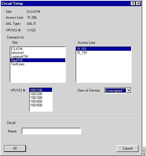
The Circuit Setup window, shown in Figure 3-25, appears.
Figure 3-25 Circuit Setup Window
Step 3
Step 4
The circuit retains the label Unnamed Circuit until you assign it a name.
Step 5
Step 6
Step 7
Configuring ATM Class of Service
For 6.0 Visual ATM ASEs and supported ATM partner devices configured in ATM-to-ATM circuits, you can assign each virtual circuit and virtual path a class of service (CoS). CoS defines how the ASE analyzes traffic passing over a circuit and how the analysis results appear in Statistics and Burst Analysis views for VCs in the Troubleshooting Toolset, and in reports generated using the Planning and Reporting Toolset.
You can select a CoS from among a standard set of five classes, five custom classes (for partner devices), and one "unassigned" class from the Class of Service drop-down list in the Network Configuration Circuit Setup window.
The PAC downloads the available classes of service in the drop-down list from the PAM. This option appears only in the Circuit Setup window for an end-to-end circuit configured between two active ATM Cisco WAPMS or partner devices. PAC users cannot manage the actual list; that task is restricted to PAM Administration. You also can define the custom classes using the PAM Administration application. (See Chapter 3, "Configuring Access Control Using PAM Administration," in the Cisco WAN Access Performance Management System System Administration Guide, 2.0.)
The five available default CoS settings affect the Troubleshooting windows and reports related to burst analysis (see the "Viewing Burst Data" section). Table 3-9 describes the five standard available CoS settings and gives the associated type of burst analysis (PCR or SCR).
Table 3-9 Descriptions of Standard ATM Classes of Service
CBR
Constant Bit Rate—ATM service category that attempts to emulate a dedicated circuit of a certain fixed bandwidth.
relative to PCR1
rtVBR
Real-time Variable Bit Rate—ATM service category in which real-time mean cell rate, Peak Cell Rate (PCR), and burst tolerance are specified. A VBR circuit takes precedence over a UBR circuit when contention arises over network resources.
relative to SCRa
nrt-VBR
Non-real-time Variable Bit Rate—ATM service category in which non-real-time mean cell rate, Peak Cell Rate (PCR), and burst tolerance are specified. A VBR circuit takes precedence over a UBR circuit when contention arises over network resources.
relative to SCRa
ABR
Available Bit Rate—ATM service category in which the network directs each transmitting end to reduce its bit transmission rate during times of congestion.
relative to SCRa
UBR
Uncommitted Bit Rate—ATM service category defined as the best effort transmission bit rate. No traffic-related service guarantees or traffic parameters are specified.
relative to SCRa
Unassigned
No class of service applied.
Varies, depending on AAL type.
1 When SCR or PCR is zero, the Troubleshooting VC Burst Analysis view is relative to (line speed) ÷ 2.
You define a CoS in PAM Administration by specifying whether the burst analysis is relative to either SCR or PCR. AAL-5 circuits are by default variable bit rate (VBR) and so, by default, the ASE performs burst analysis relative to the circuit's SCR. Non-AAL-5 circuits are by default CBR and so, by default, the ASE performs burst analysis relative to the circuit's PCR.
When you create an end-to-end circuit through the Network Configuration Circuit Setup window, its CoS is "Unassigned" by default. For this unassigned setting, traffic is analyzed according to the circuit's AAL type:
•
•
Caution
Editing and Deleting Frame Relay or ATM Circuits
These procedures apply to circuit end points (DLCIs or VPI/VCIs) and end-to-end circuits.
Editing a Circuit
Step 1
Step 2
The Circuit Setup window appears (see Figure 3-25).
Step 3
Step 4
You can delete a single circuit or multiple circuits from the PAM database. However, you cannot retrieve a circuit after you have deleted it.
Deleting a Single Circuit
Step 1
Step 2
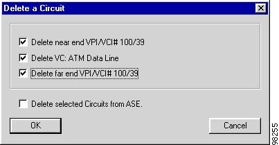
The Delete a Circuit window, shown in Figure 3-26, appears.
Figure 3-26 Delete a Circuit Window
Step 3
When the circuit end point is not part of an end-to-end circuit, only the first option is available.
Step 4
This option is available if you wish to delete the far-end mapping name only—for example, clicking Delete VC: ATM Data Line in the above example—because this attribute exists only in the PAM database.
Step 5
The selected item is removed from the PAM database configuration and the circuit is deleted from the associated ASE. However, the related network elements—network, site, and access line—remain in the configuration.
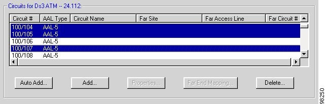
Deleting Multiple Circuits
Step 1
While making your selection, hold down the Ctrl key to select multiple individual circuits, or the Shift key to select consecutively listed circuits, as shown in Figure 3-27.
Figure 3-27 Circuits Pane in the Network Configuration Window
Step 2
The Delete Circuits window, shown in Figure 3-28, appears.
Figure 3-28 Delete Circuits Window
Step 3
This option is unavailable if you wish to delete the far-end mapping name only.
Step 4
•
•
•
•
Configuring IP Circuits
For IP Transport ASEs, the Circuits pane in the Network Configuration window shows the circuit name, far site, and far access line, as shown in Figure 3-29. Options are the same for all IP Transport ASEs. You can automatically and manually add end-to-end circuits, view circuit properties, rename a circuit, and delete single or multiple circuits.
Figure 3-29 Sample Circuits Pane of Network Configuration Window
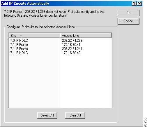
Adding an IP Circuit Automatically
You can automatically add IP circuits to a site by selecting from a list remote IP Transport sites not already having a circuit configured to the selected site. When you automatically create circuits, unnamed circuits are named using the near and far end site names.
Step 1
Figure 3-30 Add IP Circuits Automatically Window
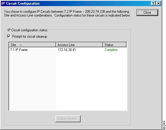
Step 2
The IP Circuit Configuration window, shown in Figure 3-31 appears, showing the status of each configured circuit. You have the following options:
•
•
Figure 3-31 IP Circuit Configuration Window
Step 3
Adding an IP Circuit Manually
When manually adding IP circuits, you can define the circuit name and a remote ASE (access line) to the circuit. When adding a remote ASE, the Circuit Setup window displays only possible remote ASEs (access lines) not already connected to the local ASE. Access lines already connected to this ASE are not displayed. The default name has 16 characters.
Note
When setting up circuits for IP Transport ASEs, keep in mind the following:
•
•
•
•
•
•
When you attempt to add a circuit and the ASE's circuit table is already full, you have the opportunity to delete older and little used circuits. For more information, see the "Cleaning Up IP Circuits" section.
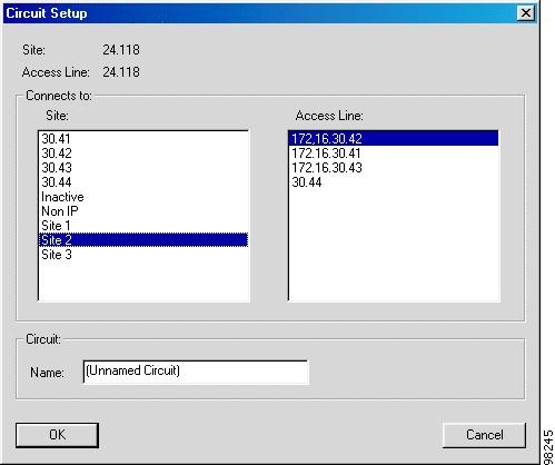
Step 1
The Circuit Setup window, shown in Figure 3-32, appears.
Figure 3-32 Circuit Setup Window - IP Circuits
Step 2
Step 3
Step 4
The default circuit name format is Unnamed Circuit.
Step 5
Once established, circuit information is added to the PAM database. The PAM then uses these circuit numbers to perform daily data collections.
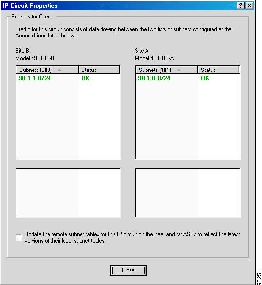
Viewing IP Circuit Properties
In the Circuit Properties window, you can view and update the local and remote subnet lists of the near and far end ASEs on an IP circuit. To access the window, from the Circuits pane of the Network Configuration window, select a circuit then click Properties.
The Circuit Properties window, shown in Figure 3-33, displays four panes:
•
•
•
•
Subnets displayed in green text with a Completed status are correctly configured. Subnets displayed in red text are incomplete. You must reconfigure and update these subnets.
•
•
When no subnets are configured for the near end or far end ASE (when the upper left or upper right fields are empty), a warning directs you to configure subnets for the ASE.
Figure 3-33 IP Circuit Properties Window
Renaming IP Circuits
From the Circuits pane of the Network Configuration window, select a circuit, then click Rename to edit the name of a circuit between two IP Transport ASEs. In the Rename Circuit window, enter the new name, then click OK to apply the change.
Deleting IP Circuits
You can delete one or more IP circuits at a time. When you delete an IP circuit, you delete the entire circuit—both its near and far sides. Deleted circuits are removed from the PAM database and the current data shown on the PAC, but they are not deleted from the ASE.
In the Circuits pane of the Network Configuration window, select one or more circuits from the list then click Delete. For a single circuit, click OK to confirm deletion.
For multiple circuits, click Yes to delete circuits one at a time, or click Yes to All to delete all circuits at once.
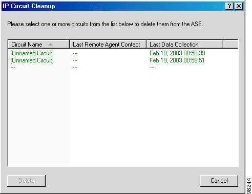
Cleaning Up IP Circuits
When the IP Transport ASE's circuit table is full when you attempt to add circuits, you must first remove old circuits. The IP Circuit Cleanup window, shown in Figure 3-34, appears with options for reviewing and deleting old or little used circuits.
You can access the IP Circuit Cleanup window from the ASE Configuration window, by clicking IP and then selecting IP Circuit Cleanup from the menu. (See Figure 3-7).
The window lists configured and unknown circuits on the IP Transport ASE and indicates:
•
•
•
Figure 3-34 IP Circuit Cleanup Window
Configuring HDLC Circuits
When configuring HDLC circuits for HDLC Multi-Protocol ASEs, you specify the access lines to be connected to form a circuit; you do not add or customize circuit end points. The Circuits pane shows the circuit number, name, far site, far access line, and far circuit number.
You can configure an HDLC circuit only between two HDLC ASEs; they cannot be co-configured with Frame Relay or ATM circuits. In addition, HDLC ASEs support only one circuit.
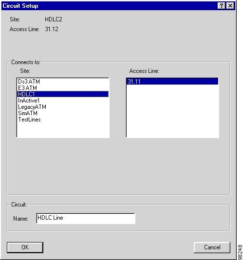
Defining the HDLC Circuit Connection
Step 1
Step 2
The HDLC Circuit Setup window, shown in Figure 3-35, appears with all network sites and HDLC access lines configured in the selected site.
Figure 3-35 HDLC Circuit Setup Window
Step 3
These elements will form the far end of the circuit.
Step 4
Step 5
Note
Note
Printing a Network Configuration Report
A Network Configuration report lists, by network, all connection information for a selected domain you normally can view through the Network Configuration window.
Step 1
A standard MS Print configuration window appears.
Step 2
The report shows all networks, sites, access lines, and circuits for the domain in which you are working.