show ip rsvp hello client lsp summary
To display summary information about Resource Reservation Protocol (RSVP) traffic engineering (TE) client hellos for label-switched paths (LSPs), use the show ip rsvp hello client lsp summary command in user EXEC or privileged EXEC mode.
show ip rsvp hello client lsp summary
Syntax Description
This command has no arguments or keywords.
Command Modes
User EXEC (>)
Privileged EXEC (#)
Command History
|
|
|
12.2(33)SB |
This command was introduced. |
12.2(33)SRC |
This command was integrated into Cisco IOS Release 12.2(33)SRA. |
Usage Guidelines
Use the show ip rsvp hello client lsp summary command to display information about the LSPs, including IP addresses and identification numbers.
Examples
The following is sample output from the show ip rsvp hello client lsp summary command:
Router# show ip rsvp hello client lsp summary
Local Remote tun_id lsp_id FLAGS
10.1.1.1 172.16.1.1 14 31 0x32
Table 85 describes the significant fields shown in the display.
Table 85 show ip rsvp hello client lsp summary Field Descriptions
|
|
|
Local |
IP address of the tunnel sender. |
Remote |
IP address of the tunnel destination. |
tun_id |
Identification number of the tunnel. |
lsp_id |
Identification number of the LSP. |
FLAGS |
Database information. |
Related Commands
|
|
|
show ip rsvp hello |
Displays hello status and statistics for fast reroute, reroute (hello state timer), and graceful restart. |
show ip rsvp hello client nbr detail
To display detailed information about Resource Reservation Protocol (RSVP) traffic engineering (TE) client hellos for neighbors, use the show ip rsvp hello client nbr detail command in user EXEC or privileged EXEC mode.
show ip rsvp hello client nbr detail [filter [destination hostname]]
Syntax Description
filter |
(Optional) Specifies filters to limit the display of output. |
destination |
(Optional) Displays the filters configured on the destination (tunnel tail). |
hostname |
(Optional) IP address or name of destination (tunnel tail). |
Command Modes
User EXEC (>)
Privileged EXEC (#)
Command History
|
|
|
12.0(33)S |
This command was introduced. |
12.2(33)SRC |
This command was integrated in Cisco IOS Release 12.2(33)SRC. |
Usage Guidelines
Use the show ip rsvp hello client nbr detail command to display information about the neighbors (nbr).
Examples
The following is sample output from the show ip rsvp hello client nbr detail command:
Router# show ip rsvp hello client nbr detail
Remote addr 10.0.0.1, Local addr 10.0.0.3
Nbr State: Normal Type: Reroute
Remote addr 172.16.1.1, Local addr 192.168.1.1
Nbr State: Normal Type: Graceful Restart
Table 86 describes the fields shown in the display
Table 86 show ip rsvp hello client nbr detail Field Descriptions
|
|
|
Remote addr |
IP address of the remote neighbor. For graceful restart, this is the neighbor router's ID; for fast reroute and hello state timer (reroute), this is one of the neighbor's interface addresses. |
Local addr |
IP address of the local neighbor. For graceful restart, this is the neighbor router's ID; for fast reroute and hello state timer (reroute), this is one of the neighbor's interface addresses. |
Nbr state |
State of the neighbor; values can be the following: • Normal—Neighbor is functioning normally. Normal—Neighbor is functioning normally. •Restarting—Neighbor is restarting. •Recover Nodal—Neighbor is recovering from node failure. •HST_GR_LOST—HST (hello state timer for reroute) is lost; waiting to see if GR (graceful restart) is also lost. •WAIT PathTear—PathTear message is delayed to allow traffic in the pipeline to be transmitted. |
Type |
Type of client: graceful restart (GR), reroute RR (hello state timer), or fast reroute (FRR). |
Nbr Hello State |
State of hello instances for the neighbor. Values are as follows: •Up—Node is communicating with its neighbor. •Lost—Communication has been lost. •Init—Communication is being established. |
LSPs protecting |
Number of LSPs being protected. |
I/F |
Interface name and number associated with the hello instance. |
Related Commands
|
|
|
show ip rsvp hello |
Displays hello status and statistics for fast reroute, reroute (hello state timer), and graceful restart. |
show ip rsvp hello client neighbor summary |
Displays summary information about RSVP TE client hellos for neighbors. |
show ip rsvp hello client neighbor detail
To display detailed information about Resource Reservation Protocol (RSVP) traffic engineering (TE) client hellos for neighbors, use the show ip rsvp hello client neighbor detail command in user EXEC or privileged EXEC mode.
show ip rsvp hello client neighbor detail
Syntax Description
This command has no arguments or keywords.
Command Modes
User EXEC (>)
Privileged EXEC (#)
Command History
|
|
|
12.0(29)S |
This command was introduced. |
12.2(33)SRA |
This command was integrated into Cisco IOS Release 12.2(33)SRA. |
12.2(33)SXH |
This command was integrated into Cisco IOS Release 12.2(33)SXH. |
12.4(20)T |
This command was integrated into Cisco IOS Release 12.4(20)T. |
Usage Guidelines
Use the show ip rsvp hello client neighbor detail command to display information about the hello neighbors, including their state and type.
Examples
The following is sample output from the show ip rsvp hello client neighbor detail command:
Router# show ip rsvp hello client neighbor detail
Remote addr 10.0.0.1, Local addr 10.0.0.3
Nbr State: Normal Type: Reroute
Remote addr 172.16.1.1, Local addr 192.168.1.1
Nbr State: Normal Type: Graceful Restart
Table 87 describes the significant fields shown in the display. The fields provide information that uniquely identifies the neighbors. Clients can include graceful restart, reroute (hello state timer), and fast reroute.
Table 87 show ip rsvp hello client neighbor detail Field Descriptions
|
|
|
Remote addr |
IP address of the remote neighbor. For graceful restart, this is the neighbor router's ID; for fast reroute and hello state timer (reroute), this is one of the neighbor's interface addresses. |
Local addr |
IP address of the local neighbor. For graceful restart, this is the neighbor router's ID; for fast reroute and hello state timer (reroute), this is one of the neighbor's interface addresses. |
Nbr State |
State of the neighbor; values can be the following: •Normal = neighbor is functioning normally. •Restarting = neighbor is restarting. •Recover Nodal = neighbor is recovering from node failure. •HST_GR_LOST = HST (hello state timer for reroute) is lost; waiting to see if graceful restart (GR) is also lost. •WAIT PathTear = PathTear message is delayed to allow traffic in the pipeline to be transmitted. |
Type |
Type of client; graceful restart, Reroute (hello state timer), or Fast Reroute. |
Nbr Hello State |
State of hellos for the neighbor. Values are as follows: •Up—Node is communicating with its neighbor. •Lost—Communication has been lost. •Init—Communication is being established. |
LSPs protecting |
Number of LSPs being protected. |
I/F |
Interface name and number associated with the hello instance. |
Related Commands
|
|
|
show ip rsvp hello |
Displays hello status and statistics for fast reroute, reroute (hello state timer), and graceful restart. |
show ip rsvp hello client neighbor summary
To display summary information about Resource Reservation Protocol (RSVP) traffic engineering (TE) client hellos for neighbors, use the show ip rsvp hello client neighbor summary command in user EXEC or privileged EXEC mode.
show ip rsvp hello client neighbor summary
Syntax Description
This command has no arguments or keywords.
Command Modes
User EXEC (>)
Privileged EXEC (#)
Command History
|
|
|
12.0(29)S |
This command was introduced. |
12.2(33)SRA |
This command was integrated into Cisco IOS Release 12.2(33)SRA. |
12.2(33)SXH |
This command was integrated into Cisco IOS Release 12.2(33)SXH. |
12.4(20)T |
This command was integrated into Cisco IOS Release 12.4(20)T. |
Usage Guidelines
Use the show ip rsvp hello client neighbor summary command to display information about the neighbors, including state, type, and hello instance status.
Examples
The following is sample output from the show ip rsvp hello client neighbor summary command:
Router# show ip rsvp hello client neighbor summary
Local Remote Type NBR_STATE HI_STATE LSPs
10.0.0.1 10.0.0.3 RR Normal Up 1
172.16.1.1 192.168.1.1 GR Normal Lost 1
Table 88 describes the significant fields shown in the display.
Table 88 show ip rsvp hello client neighbor summary Field Descriptions
|
|
|
Local |
IP address of the tunnel sender. |
Remote |
IP address of the tunnel destination. |
Type |
Type of client; graceful restart (GR), reroute (RR (hello state timer)), or fast reroute (FRR). |
NBR_STATE |
State of the neighbor; values can be the following: •Normal—Neighbor is functioning normally. •Restarting—Neighbor is restarting. •Recover Nodal—Neighbor is recovering from node failure. •HST_GR_LOST—HST (hello state timer for reroute) is lost; waiting to see if graceful restart (GR) is also lost. •WAIT PathTear—PathTear message is delayed to allow traffic in the pipeline to be transmitted. |
HI_STATE |
State of hello instances for the neighbor. Values are as follows: •Up—Node is communicating with its neighbor. •Lost—Communication has been lost. •Init—Communication is being established. |
LSPs |
Number of LSPs going to or coming from the neighbor. |
Related Commands
|
|
|
show ip rsvp hello |
Displays hello status and statistics for fast reroute, reroute (hello state timer), and graceful restart. |
show ip rsvp hello graceful-restart
To display information about Resource Reservation Protocol (RSVP) traffic engineering (TE) graceful restart hellos, use the show ip rsvp hello graceful-restart command in user EXEC or privileged EXEC mode.
show ip rsvp hello graceful-restart
Syntax Description
This command has no arguments or keywords.
Command Modes
User EXEC (>)
Privileged EXEC (#)
Command History
|
|
|
12.0(29)S |
This command was introduced. |
12.2(33)SRA |
The command output was modified to show whether graceful restart is configured and full mode was added. |
12.2(33)SXH |
This command was integrated into Cisco IOS Release 12.2(33)SXH. |
12.4(20)T |
This command was integrated into Cisco IOS Release 12.4(20)T. |
Usage Guidelines
Use the show ip rsvp hello graceful-restart command to display the status of graceful restart and related statistics.
Examples
The following is sample output from the show ip rsvp hello graceful-restart command:
Router# show ip rsvp hello graceful-restart
Graceful Restart: Enabled (full mode)
Refresh interval: 10000 msecs
Advertised restart time: 30000 msecs
Advertised recovery time: 120000 msecs
Maximum wait for recovery: 3600000 msecs
Table 89 describes the significant fields shown in the display.
Table 89 show ip rsvp hello graceful-restart Field Descriptions
|
|
|
Graceful Restart |
Restart capability: •Enabled—Restart capability is activated for a router (full mode) or its neighbor (help-neighbor). •Disabled—Restart capability is not activated. |
Refresh interval |
Frequency in milliseconds (ms) with which a node sends a hello message to its neighbor. |
Refresh misses |
Number of missed hello messages that trigger a neighbor down event upon which stateful switchover (SSO) procedures are started. |
DSCP |
The differentiated services code point (DSCP) value in the IP header of the hello messages. |
Advertised restart time |
The time, in ms, that is required for the sender to restart the RSVP-TE component and exchange hello messages after a failure. |
Advertised recovery time |
The time, in ms, within which a recovering node wants its neighbor router to resynchronize the RSVP or Multiprotocol Label Switching (MPLS) forwarding state after SSO. Note A zero value indicates that the RSVP or MPLS forwarding state is not preserved after SSO. |
Maximum wait for recovery |
The maximum amount of time, in ms, that the router waits for a neighbor to recover. |
Related Commands
|
|
|
clear ip rsvp high-availability counters |
Clears (sets to zero) the RSVP-TE HA counters that are being maintained by an RP. |
ip rsvp signalling hello graceful-restart mode |
Enables RSVP-TE graceful restart support capability on an RP. |
ip rsvp signalling hello graceful-restart neighbor |
Enables RSVP-TE graceful restart support capability on a neighboring router. |
show ip rsvp hello |
Displays hello status and statistics for fast reroute, reroute (hello state timer), and graceful restart. |
show ip rsvp hello instance detail
To display detailed information about a hello instance, use the show ip rsvp hello instance detail command in user EXEC or privileged EXEC mode.
show ip rsvp hello instance detail [filter destination ip-address]
Syntax Description
filter destination ip-address |
(Optional) IP address of the neighbor node. |
Command Modes
User EXEC (>)
Privileged EXEC (#)
Command History
|
|
|
12.0(22)S |
This command was introduced. |
12.0(29)S |
The command output was modified to include graceful restart, hello state timer (reroute), and fast reroute information. |
12.2(18)SXD1 |
This command was integrated into Cisco IOS Release 12.2(18)SXD1. |
12.2(33)SRA |
This command was integrated into Cisco IOS Release 12.2(33)SRA. |
12.2(31)SB2 |
This command was integrated into Cisco IOS Release 12.2(31)SB2. |
12.4(20)T |
This command was integrated into Cisco IOS Release 12.4(20)T. |
Usage Guidelines
Use the show ip rsvp hello instance detail command to display information about the processes (clients) currently configured.
Examples
The following is sample output from the show ip rsvp hello instance detail command:
Router# show ip rsvp hello instance detail
Neighbor 10.0.0.3 Source 10.0.0.2
Type: Active (sending requests)
State: Up (for 2d19h2d19h)
Missed acks: 4, IP DSCP: 0x30
Statistics: (from 40722 samples)
Waverage: 6000 (Weight = 0.8)
Last sent Src_instance: 0xE617C847
Last recv nbr's Src_instance: 0xFEC28E95
Communication with neighbor lost:
Neighbor disabled Hello: 0
Neighbor 10.0.0.8 Source 10.0.0.7
Type: Passive (responding to requests)
Last sent Src_instance: 0xF7A80A52
Last recv nbr's Src_instance: 0xD2F1B7F7
Table 90 describes the significant fields shown in the display.
Table 90 show ip rsvp hello instance detail Field Descriptions
|
|
|
Neighbor |
IP address of the adjacent node. |
Source |
IP address of the node that is sending the hello message. |
Type |
Values are Active (node is sending a request) and Passive (node is responding to a request). |
I/F |
Interface from which hellos are sent for this instance. Any means that the hellos can be sent out any interface. |
State |
Status of communication. Values are as follows: •Up—Node is communicating with its neighbor. •Lost—Communication has been lost. •Init—Communication is being established. |
Clients |
Clients that created this hello instance; they include graceful restart, ReRoute (hello state timer), and Fast Reroute. |
LSPs protecting |
Number of LSPs that are being protected by this hello instance. |
Missed acks |
Number of times that communication was lost due to missed acknowledgments (ACKs). |
IP DSCP |
IP differentiated services code point (DSCP) value used in the hello IP header. |
Refresh Interval (msec) |
The frequency (in milliseconds) with which a node generates a hello message containing a Hello Request object for each neighbor whose status is being tracked. |
Configured |
Configured refresh interval. |
Statistics |
Refresh interval statistics from a specified number of samples (packets). |
Min |
Minimum refresh interval. |
Max |
Maximum refresh interval. |
Average |
Average refresh interval. |
Waverage |
Weighted average refresh interval. |
Current |
Current refresh interval. |
Last sent Src_instance |
The last source instance sent to a neighbor. |
Last recv nbr's Src_instance |
The last source instance field value received from a neighbor. (0 means none received.) |
Counters |
Incremental information relating to communication with a neighbor. |
Num times |
Total number of times that communication with a neighbor was lost. |
Reasons |
Subsequent fields designate why communication with a neighbor was lost. |
Missed acks |
Number of times that communication was lost due to missed ACKs. |
Bad Src_Inst received |
Number of times that communication was lost due to bad source instance fields. |
Bad Dst_Inst received |
Number of times that communication was lost due to bad destination instance fields. |
I/F went down |
Number of times that the interface became unoperational. |
Neighbor disabled Hello |
Number of times that a neighbor disabled hello messages. |
Msgs Received |
Number of messages that were received. |
Sent |
Number of messages that were sent. |
Suppressed |
Number of messages that were suppressed due to optimization. |
Related Commands
|
|
|
ip rsvp signalling hello (configuration) |
Enables hello globally on the router. |
ip rsvp signalling hello statistics |
Enables hello statistics on the router. |
show ip rsvp hello |
Displays hello status and statistics for Fast reroute, reroute (hello state timer), and graceful restart. |
show ip rsvp hello instance summary |
Displays summary information about a hello instance. |
show ip rsvp hello instance summary
To display summary information about a hello instance, use the show ip rsvp hello instance summary command in user EXEC or privileged EXEC mode.
show ip rsvp hello instance summary
Syntax Description
This command has no arguments or keywords.
Command Modes
User EXEC
Privileged EXEC
Command History
|
|
|
12.0(22)S |
This command was introduced. |
12.0(29)S |
The command output was modified to include graceful restart, reroute (hello state timer), and fast reroute information. |
12.2(18)SXD1 |
This command was integrated into Cisco IOS Release 12.2(18)SXD1. |
12.2(33)SRA |
This command was integrated into Cisco IOS Release 12.2(33)SRA. |
12.2(31)SB2 |
This command was integrated into Cisco IOS Release 12.2(31)SB2. |
12.4(20)T |
This command was integrated into Cisco IOS Release 12.4(20)T. |
Examples
The following is sample output from the show ip rsvp hello instance summary command:
Router# show ip rsvp hello instance summary
Client Neighbor I/F State LostCnt LSPs Interval
RR 10.0.0.3 Se2/0 Up 0 1 6000
GR 10.1.1.1 Any Up 13 1 10000
GR 10.1.1.5 Any Lost 0 1 10000
GR 10.2.2.1 Any Init 1 0 5000
Active = Actively tracking neighbor state on behalf of clients:
RR = ReRoute, FRR = Fast ReRoute, or GR = Graceful Restart
Passive = Responding to hello requests from neighbor
Table 91 describes the significant fields shown in the display.
Table 91 show ip rsvp hello instance summary Field Descriptions
|
|
|
Active Instances |
Active nodes that are sending hello requests. |
Client |
Clients on behalf of which hellos are sent; they include GR (graceful restart), RR (reroute = hello state timer), and FRR (Fast Reroute). |
Neighbor |
IP address of the adjacent node. For graceful restart, this is the neighbor router's ID; for Fast Reroute and hello state timer (reroute), this is one of the neighbor's interface addresses. |
I/F |
Interface from which hellos are sent for this instance. Any means that the hellos can be sent out any interface. |
State |
Status of communication. Values are as follows: •Up—Node is communicating with its neighbor. •Lost—Communication has been lost. •Init—Communication is being established. |
LostCnt |
Number of times that communication was lost with the neighbor. |
LSPs |
Number of label-switched paths (LSPs) protected by this hello instance. |
Interval |
Hello refresh interval in milliseconds. |
Passive Instances |
Passive nodes that are responding to hello requests. |
Neighbor |
IP address of adjacent node. For graceful restart, this is the neighbor router's ID; for Fast Reroute and hello state timer (reroute), this is one of the neighbor's interface addresses. |
I/F |
Interface from which hellos are sent for this instance. Any means that the hellos can be sent out any interface. |
Related Commands
|
|
|
ip rsvp signalling hello (configuration) |
Enables hello globally on the router. |
ip rsvp signalling hello statistics |
Enables hello statistics on the router. |
show ip rsvp hello |
Displays hello status and statistics for fast reroute, reroute (hello state timer), and graceful restart. |
show ip rsvp hello instance detail |
Displays detailed information about a hello instance. |
show ip rsvp hello statistics
To display how long hello packets have been in the hello input queue, use the show ip rsvp hello statistics command in user EXEC or privileged EXEC mode.
show ip rsvp hello statistics
Syntax Description
This command has no arguments or keywords.
Command Default
Information about how long hello packets have been in the hello input queue is not displayed.
Command Modes
User EXEC (>)
Privileged EXEC (#)
Command History
|
|
|
12.0(22)S |
This command was introduced. |
12.2(18)SXD1 |
This command was integrated into Cisco IOS Release 12.2(18)SXD1. |
12.2(33)SRA |
This command was integrated into Cisco IOS Release 12.2(33)SRA. |
12.2(31)SB2 |
This command was integrated into Cisco IOS Release 12.2(31)SB2. |
12.4(20)T |
This command was integrated into Cisco IOS Release 12.4(20)T |
Usage Guidelines
You can use this command to determine if the hello refresh interval is too small. If the interval is too small, communication may falsely be declared as lost.
Examples
The following is sample output from the show ip rsvp hello statistics command:
Router# show ip rsvp hello statistics
Weighted Average:0 (weight = 0.8)
Current length: 0 (max:500)
Number of samples taken: 2398525
Table 92 describes the significant fields shown in the display.
Table 92 show ip rsvp hello statistics Field Descriptions
|
|
|
Status |
Indicator of whether Hello has been enabled globally on the router. |
Current |
Amount of time, in milliseconds, that the current hello packet has been in the Hello input queue. |
Average |
Average amount of time, in milliseconds, that hello packets are in the Hello input queue. |
Max |
Maximum amount of time, in milliseconds, that hello packets have been in the Hello input queue. |
Current length |
Current amount of time, in milliseconds, that hello packets have been in the Hello input queue. |
Number of samples taken |
Number of packets for which these statistics were compiled. |
Related Commands
|
|
|
clear ip rsvp hello instance statistics |
Clears hello statistics for an instance. |
clear ip rsvp hello statistics |
Clears hello statistics globally. |
ip rsvp signalling hello refresh interval |
Configures the hello request interval. |
ip rsvp signalling hello statistics |
Enables hello statistics on a router. |
show ip rsvp high-availability counters
To display all Resource Reservation Protocol (RSVP) traffic engineering (TE) high availability (HA) counters that are being maintained by a Route Processor (RP), use the show ip rsvp high-availability counters command in user EXEC or privileged EXEC mode.
show ip rsvp high-availability counters
Syntax Description
This command has no arguments or keywords.
Command Modes
User EXEC (>)
Privileged EXEC (#)
Command History
|
|
|
12.2(33)SRA |
This command was introduced. |
12.2(33)SRB |
Support for In-Service Software Upgrade (ISSU) was added. |
12.2(33)SXH |
This command was integrated into Cisco IOS Release 12.2(33)SXH. |
15.0(1)S |
This command was modified. The output was updated to display information for point-to-point (P2P) and point-to-multipoint traffic engineering (P2MP) counters. |
Usage Guidelines
Use the show ip rsvp high-availability counters command to display the HA counters, which include state, ISSU, checkpoint messages, resource failures, and errors.
The command output differs depending on whether the RP is active or standby. (See the "Examples" section for more information.)
Use the clear ip rsvp high-availability counters command to clear all counters.
Examples
The following is sample output from the show ip rsvp high-availability counters command on the active RP:
Router# show ip rsvp high-availability counters
P2P LSPs for which recovery:
P2MP subLSPs for which recovery:
Checkpoint Messages (Items) Sent
Checkpoint Messages Transformed:
Historical: (When Active was Standby)
Checkpoint Messages (Items) Received
Table 93 describes the significant fields shown in the display.
Table 93 show ip rsvp high-availability counters—Active RP Field Descriptions
|
|
|
State |
The RP state: •Active—Active RP. |
Bulk sync |
The number of requests made by the standby RP to the active RP to resend all write database entries: •Initiated—The number of bulk sync operations initiated by the standby RP since reboot. |
Send timer |
The write database timer. |
Checkpoint Messages (Items) Sent |
The details of the bundle messages or items sent since booting. |
Succeeded |
The number of bundle messages or items sent from the active RP to the standby RP since booting. Values are the following: •Acks accepted—The number of bundle messages or items sent from the active RP to the standby RP. •Acks ignored—The number of bundle messages or items sent by the active RP, but rejected by the standby RP. •Nacks—The number of bundle messages or items given to the checkpointing facility (CF) on the active RP for transmitting to the standby RP, but failed to transmit. |
Failed |
The number of bundle messages or items the active RP attempted to send the standby RP when the send timer updated, but received an error back from CF. |
Buffer alloc |
Storage space allocated. |
Buffer freed |
Storage space available. |
ISSU |
In-Service Software Upgrade (ISSU) counters. |
Checkpoint Messages Transformed |
The details of the bundle messages or items transformed (upgraded or downgraded for compatibility) since booting so that the active RP and the standby RP can interoperate. |
On Send |
The number of messages sent by the active RP that succeeded, failed, or were transformations. |
On Recv |
The number of messages received by the active RP that succeeded, failed, or were transformations. |
Negotiation |
The number of times that the active RP and the standby RP have negotiated their interoperability parameters. |
Started |
The number of negotiations started. |
Finished |
The number of negotiations finished. |
Failed to Start |
The number of negotiations that failed to start. |
Messages |
The number of negotiation messages sent and received. These messages can be succeeded or failed. •Send succeeded—Number of messages sent successfully. •Send failed—Number of messages sent unsuccessfully. •Buffer allocated—Storage space allowed. •Buffer freed—Storage space available. •Buffer alloc failed—No storage space available. |
Init |
The number of times the RSVP ISSU client has successfully and unsuccessfully (failed) initialized. |
Session Registration |
The number of session registrations, succeeded and failed, performed by the active RP whenever the standby RP reboots. |
Session Unregistration |
The number of session unregistrations, succeeded and failed, before the standby RP resets. |
Errors |
The details of errors or caveats. |
The following is sample output from the show ip rsvp high-availability counters command on the standby RP:
Router# show ip rsvp high-availability counters
Checkpoint Messages (Items) Received
Checkpoint Messages Transformed:
Table 94 describes the significant fields shown in the display.
Table 94 show ip rsvp high-availability counters—Standby RP Field Descriptions
|
|
|
State |
The RP state: •Standby—Standby (backup) RP. |
Checkpoint Messages (Items) Received |
The details of the messages or items received by the standby RP. Values are the following: •Valid—The number of valid messages or items received by the standby RP. •Invalid—The number of invalid messages or items received by the standby RP. •Buffer freed—Amount of storage space available. |
ISSU |
ISSU counters. Note For descriptions of the ISSU fields, see Table 93. |
Errors |
The details of errors or caveats. |
Related Commands
|
|
|
clear ip rsvp high-availability counters |
Clears (sets to zero) the RSVP-TE HA counters that are being maintained by an RP. |
show ip rsvp high-availability database |
Displays the contents of the RSVP-TE HA read and write databases used in TE SSO. |
show ip rsvp high-availability summary |
Displays summary information for an RSVP-TE HA RP. |
show ip rsvp high-availability database
To display the contents of the Resource Reservation Protocol (RSVP) high availability (HA) read and write databases used in traffic engineering (TE), use the show ip rsvp high-availability database command in user EXEC or privileged EXEC mode.
show ip rsvp high-availability database {hello | link-management {interfaces [fixed | variable] | system} | lsp [filter destination ip-address | filter lsp-id lsp-id | filter source ip-address | filter tunnel-id tunnel-id] | lsp-head [filter number] | summary}
Syntax Description
hello |
Displays information about the hello entries in the read and write databases. |
link-management |
Displays information about the link-management entries in the read and write databases. |
interfaces |
Displays information about the link-management interfaces in the read and write databases. |
fixed |
(Optional) Displays information about the link-management fixed interfaces in the read and write databases. |
variable |
(Optional) Displays information about the link-management variable interfaces in the read and write databases. |
system |
Displays information about the link-management system in the read and write databases. |
lsp |
Displays information about the label switched path (LSP) entries in the read and write databases. |
filter destination ip-address |
(Optional) Displays filtered information on the IP address of the destination (tunnel tail). |
filter lsp-id lsp-id |
(Optional) Displays filtered information on a specific LSP ID designated by a number from 0 to 65535. |
filter source ip-address |
(Optional) Displays filtered information on the IP address of the source (tunnel head). |
filter tunnel-id tunnel-id |
(Optional) Displays filtered information on a specific tunnel ID designated by a number from 0 to 65535. |
lsp-head |
Displays information about the LSP-head entries in the read and write databases. |
filter number |
(Optional) Displays filtered information on a specific LSP-head router designated by a number from 0 to 65535. |
summary |
Displays cumulative information about the entries in the read and write databases. |
Command Modes
User EXEC (>)
Privileged EXEC (#)
Command History
|
|
|
12.2(33)SRA |
This command was introduced. |
12.2(33)SRB |
The command output was modified to display the result of a loose hop expansion performed on the router. |
12.2(33)SXH |
This command was integrated into Cisco IOS Release 12.2(33)SXH. |
12.2(33)SRC |
This command was integrated into Cisco IOS Release 12.2(33)SRC. The command output was modified to include path protection information if you specify the lsp-head keyword. |
12.4(20)T |
This command was integrated into Cisco IOS Release 12.4(20)T. |
15.0(1)S |
This command was integrated into Cisco IOS Release 15.0(1)S. The command output was modified to distinguish database-entry information for point-to-point (P2P) tunnels from that for point-to-multipoint (P2MP) tunnels and to display error database information. |
Usage Guidelines
Use the show ip rsvp high-availability database command to display information about the entries in the read and write databases.
Use the show ip rsvp high-availability database lsp command to display loose hop information. A loose hop expansion can be performed on a router when the router processes the explicit router object (ERO) for an incoming path message. After the router removes all local IP addresses from the incoming ERO, it finds the next hop. If the ERO specifies that the next hop is loose instead of strict, the router consults the TE topology database and routing to determine the next hop and output interface to forward the path message. The result of the calculation is a list of hops; that list is placed in the outgoing ERO and checkpointed with the LSP data as the loose hop information.
In Cisco IOS Release 15.0(1)S and later releases, the show ip rsvp high-availability database lsp command displays sub-LSP information. If any sub-LSP, whether P2MP or P2P, fails to recover after an SSO switchover, the failure is noted in an error database for troubleshooting. You can use the show ip rsvp high database lsp command to display the error database entries.
Use the show ip rsvp high-availability database lsp-head command on a headend router only. On other routers, this command gives no information.
Examples
Hello Example on Active RP
The following is sample output from the show ip rsvp high-availability database hello command on an active Route Processor (RP):
Router# show ip rsvp high-availability database hello
State: Checkpointed Action: Add
Last sent Src_instance: 0xDE435865
Table 95 describes the significant fields shown in the display.
Table 95 show ip rsvp high-availability database hello—Active RP Field Descriptions
|
|
|
HELLO WRITE DB |
Storage area for active RP hello data consisting of checkpointed RSVP-TE information that is sent to the standby RP when it becomes the active RP and needs to recover LSPs. This field is blank on a standby RP. |
Header |
Header information. |
State |
Status of an entry. Values are as follows: •Ack-Pending—Entries have been sent, but not acknowledged. •Checkpointed—Entries have been sent and acknowledged by the standby RP. •Send-Pending—Entries are waiting to be sent. |
Action |
Action taken. Values are as follows: •Add—Adding an item to the standby RP. •Delete—Deleting an item from the standby RP. This action appears temporarily while the active RP awaits an acknowledgment (ack) of the delete operation. •Modify—Modifying an item on the standby RP. •Remove—Removing an item from the standby RP. |
Seq # |
Number used by the active and standby RPs to synchronize message acks and negative acknowledgments (nacks) to messages sent. |
Flags |
Attribute used to identify or track data. |
Data |
Information about the last transmission. |
Last sent Src_instance |
Last source instance identifier sent. |
HELLO READ DB |
Storage area for standby RP hello data. This field is blank on an active RP except when it is in recovery mode. |
Hello Example on Standby RP
The following is sample output from the show ip rsvp high-availability database hello command on a standby RP:
Router# show ip rsvp high-availability database hello
State: Checkpointed Action: Add
Last sent Src_instance: 0xDE435865
These fields are the same as those for the active RP described in Table 95 except they are now in the read database for the standby RP.
Link-Management Interfaces Example on an Active RP
The following is sample output from the show ip rsvp high-availability database link-management interfaces command on an active RP:
Router# show ip rsvp high-availability database link-management interfaces
Flooding Protocol: ospf IGP Area ID: 0 Link ID: 0 (GigabitEthernet3/2)
State: Checkpointed Action: Add
Ifnumber: 5 Link Valid Flags: 0x193B
Link Subnet Type: Broadcast
Local Intfc ID: 0 Neighbor Intf ID: 0
Link IP Address: 172.16.3.1
Neighbor IGP System ID: 172.16.3.2 Neighbor IP Address: 10.0.0.0
IGP Metric: 1 TE Metric: 1
Physical Bandwidth: 1000000 kbits/sec
Res. Global BW: 3000 kbits/sec
Reservable Bandwidth[0]: 0 0 kbits/sec
Reservable Bandwidth[1]: 0 0 kbits/sec
Reservable Bandwidth[2]: 0 0 kbits/sec
Reservable Bandwidth[3]: 0 0 kbits/sec
Reservable Bandwidth[4]: 0 0 kbits/sec
Reservable Bandwidth[5]: 0 0 kbits/sec
Reservable Bandwidth[6]: 0 0 kbits/sec
Reservable Bandwidth[7]: 0 0 kbits/sec
Reservable Bandwidth[0]: 3000 0 kbits/sec
Reservable Bandwidth[1]: 3000 0 kbits/sec
Reservable Bandwidth[2]: 3000 0 kbits/sec
Reservable Bandwidth[3]: 3000 0 kbits/sec
Reservable Bandwidth[4]: 3000 0 kbits/sec
Reservable Bandwidth[5]: 3000 0 kbits/sec
Reservable Bandwidth[6]: 3000 0 kbits/sec
Reservable Bandwidth[7]: 2900 0 kbits/sec
Protection Type: Capability 0, Working Priority 0
Table 96 describes the significant fields shown in the display.
Table 96 show ip rsvp high-availability database link-management interfaces—Active RP Field Descriptions
|
|
|
TE LINK WRITE DB |
Storage area for active TE RP link data. This field is blank on a standby RP. |
Flooding Protocol |
Protocol that is flooding information for this area. ospf = Open Shortest Path First. |
IGP Area ID |
Interior Gateway Protocol (IGP) identifier for the area being flooded. |
Link ID |
Link identifier and interface for the area being flooded. |
Header |
Header information. |
State |
Status of an entry. Values are as follows: •Ack-Pending—Entries have been sent, but not acknowledged. •Checkpointed—Entries have been sent and acknowledged by the standby RP. •Send-Pending—Entries are waiting to be sent. |
Action |
Action taken. Values are as follows: •Add—Adding an item to the standby RP. •Delete—Deleting an item from the standby RP. This action appears temporarily while the active RP awaits an ack of the delete operation. •Modify—Modifying an item on the standby RP. •Remove—Removing an item from the standby RP. |
Seq # |
Number used by the active and standby RPs to synchronize message acks and nacks to messages sent. |
Flags |
Attribute used to identify or track data. |
Data |
Information about the last transmission. |
Ifnumber |
Interface number. |
Link Valid Flags |
Attributes used to identify or track links. |
Link Subnet Type |
Subnet type of the link. Values are as follows: •Broadcast—Data for multiple recipients. •Nonbroadcast Multiaccess—A network in which data is transmitted directly from one computer to another over a virtual circuit or across a switching fabric. •Point-to-Multipoint—Unidirectional connection in which a single source end system (known as a root node) connects to multiple destination end systems (known as leaves). •Point-to-Point—Unidirectional or bidirectional connection between two end systems. •Unknown subnet type—Subnet type not identified. |
Local Intfc ID |
Local interface identifier. |
Neighbor Intf ID |
Neighbor's interface identifier. |
Link IP Address |
IP address of the link. |
Neighbor IGP System ID |
Neighbor system identifier configured using IGP. |
Neighbor IP Address |
Neighbor's IP address. |
IGP Metric |
Metric value for the TE link configured using IGP. |
TE Metric |
Metric value for the TE link configured using Multiprotocol Label Switching (MPLS) TE. |
Physical Bandwidth |
Link bandwidth capacity in kilobits per second (kb/s). |
Res. Global BW |
Amount of reservable global pool bandwidth (in kb/s) on this link. |
Res. Sub BW |
Amount of reservable subpool bandwidth (in kb/s) on this link. |
Upstream |
Header for the following section of bandwidth values. |
Global Pool |
Global pool bandwidth (in kb/s) on this link. |
Sub Pool |
Subpool bandwidth (in kb/s) on this link. |
Reservable Bandwidth [1] |
Amount of bandwidth (in kb/s) available for reservations in the global TE topology and subpools. |
Downstream |
Header for the following section of bandwidth values. |
Affinity Bits |
Link attributes required in tunnels. |
Protection Type |
LSPs protected by fast reroute (FRR). •Capability = LSPs capable of using FRR. •Working Priority = LSPs actually using FRR. |
Number of TLVs |
Number of type, length, values (TLVs). |
The fields for a standby RP are the same as those described in Table 96 except they are now in the TE link read database instead of the TE link write database that is used by an active RP.
Link-Management System Example on an Active RP
The following is sample output from the show ip rsvp high-availability database link-management system command on an active RP:
Router# show ip rsvp high-availability database link-management system
Flooding Protocol: OSPF IGP Area ID: 0
State: Checkpointed Action: Modify
LSA Valid flags: 0x0 Node LSA flag: 0x0
IGP System ID: 172.16.3.1 MPLS TE Router ID: 10.0.0.3
Flooded links: 1 TLV length: 0 (bytes)
Table 97 describes the significant fields shown in the display.
Table 97 show ip rsvp high-availability database link-management system—Active RP Field Descriptions
|
|
|
TE SYSTEM WRITE DB |
Storage area for active TE RP system data. This field is blank on a standby RP. |
Flooding Protocol |
Protocol that is flooding information for this area. OSPF = Open Shortest Path First. |
IGP Area ID |
IGP identifier for the area being flooded. |
Header |
Header information. |
State |
Status of an entry. Values are as follows: •Ack-Pending—Entries have been sent, but not acknowledged. •Checkpointed—Entries have been sent and acknowledged by the standby RP. •Send-Pending—Entries are waiting to be sent. |
Action |
Action taken. Values are as follows: •Add—Adding an item to the standby RP. •Delete—Deleting an item from the standby RP. This action appears temporarily while the active RP awaits an ack of the delete operation. •Modify—Modifying an item on the standby RP. •Remove—Removing an item from the standby RP. |
Seq # |
Number used by the active and standby RPs to synchronize message acks and nacks to messages sent. |
Flags |
Attribute used to identify or track data. |
Data |
Information about the last transmission. |
LM Flood Data |
Link management (LM) flood data. |
LSA Valid flags |
Link-state advertisement (LSA) attributes. |
Node LSA flag |
LSA attributes used by a router. |
IGP System ID |
Identification (IP address) that IGP flooding uses in this area to identify this node. |
MPLS TE Router ID |
MPLS TE router identifier (IP address). |
Flooded links |
Number of flooded links. |
TLV length |
TLV length in bytes. |
Fragment id |
Fragment identifier for this link. |
TE SYSTEM READ DB |
Storage area for standby TE RP system data. This field is blank on a standby RP. |
The fields for a standby RP are the same as those described in Table 97 except they are now in the TE system read database instead of the TE system write database that is used by an active RP.
LSP Example on an Active RP for a P2P Tunnel
The following is sample output from the show ip rsvp high-availability database lsp command on an active RP for a P2P tunnel:
Router# show ip rsvp high-availability database lsp
Tun ID: 0 LSP ID: 10 (P2P)
Sender: 10.1.0.1 Ext. Tun ID: 10.1.0.1
State: Checkpointed Action: Add
LSP Example on an Active RP for a P2MP Tunnel
The following is sample output from the show ip rsvp high-availability database lsp command on an active RP for a P2MP tunnel:
Router# show ip rsvp high-availability database lsp
Tun ID: 1 LSP ID: 127 (P2MP)
Sender: 10.1.0.1 Ext. Tun ID: 10.1.0.1
State: Checkpointed Action: Add
Lspvif if_num: 35 (Lspvif0)
Table 98 describes the significant fields shown in the display.
Table 98 show ip rsvp high-availability database lsp—Active RP Field Descriptions
|
|
|
P2P/P2MP |
Tunnel type. |
Subgrp ID |
Subgroup identifier (valid only for P2MP TE LSPs). |
Subgrp Orig |
Subgroup origin IP address (valid only for P2MP TE LSPs). |
Lspvif if_num |
Interface number of the LSPVIF (valid only for P2MP TE tailends). |
PathSet ID |
Path set identifier (valid only for P2MP TE LSPs) |
LSP WRITE DB |
Storage area for active RP LSP data. This field is blank on a standby RP. |
Tun ID |
Tunnel identifier. |
LSP ID |
LSP identifier. |
Dest |
Tunnel destination IP address. |
Sender |
Tunnel sender IP address. |
Ext. Tun ID |
Extended tunnel identifier; usually set to 0 or the sender's IP address. |
Header |
Header information. |
State |
Status of an entry. Values are as follows: •Ack-Pending—Entries have been sent, but not acknowledged. •Checkpointed—Entries have been sent and acknowledged by the standby RP. •Send-Pending—Entries are waiting to be sent. |
Action |
Action taken. Values are as follows: •Add—Adding an item to the standby RP. •Delete—Deleting an item from the standby RP. This action appears temporarily while the active RP awaits an ack of the delete operation. •Modify—Modifying an item on the standby RP. •Remove—Removing an item from the standby RP. |
Seq # |
Number used by the active and standby RPs to synchronize message acks and nacks to messages sent. |
Flags |
Attribute used to identify or track data. |
Data |
Information about the last transmission. |
InLabel |
Incoming label identifier. |
Out I/F |
Outgoing interface. |
Next-Hop |
Next hop IP address. |
OutLabel |
Outgoing label identifier. |
Loose hop info |
Lists the loose hop expansions performed on the router, or specifies None. |
LSP READ DB |
Storage area for standby RP LSP data. This field is blank on an active RP. |
The fields for a standby RP are the same as those described in Table 98 except they are now in the LSP read database instead of the LSP write database that is used by an active RP.
LSP-Head Example on an Active RP for a P2P Tunnel
The following is sample output from the show ip rsvp high-availability database lsp-head command on an active RP for a P2P tunnel:
Router# show ip rsvp high-availability database lsp-head
State: Checkpointed Action: Add
lsp_id: 10, bandwidth: 5, thead_flags: 0x1, popt: 1
output_if_num: 11, output_nhop: 10.1.3.2
Destination: 10.3.0.1, Id: 10.3.0.1 Router Node (ospf) flag:0x0
IGP: ospf, IGP area: 0, Number of hops: 3, metric: 128
Hop 0: 10.1.3.2, Id: 10.2.0.1 Router Node (ospf), flag:0x0
Hop 1: 10.2.3.3, Id: 10.3.0.1 Router Node (ospf), flag:0x0
Hop 2: 10.3.0.1, Id: 10.3.0.1 Router Node (ospf), flag:0x0
LSP-Head Example on an Active RP for a P2MP Tunnel
The following is sample output from the show ip rsvp high-availability database lsp-head command on an active RP for a P2MP tunnel:
Router# show ip rsvp high-availability database lsp-head
State: Checkpointed Action: Add
lsp_id: 11, bandwidth: 100, thead_flags: 0x1, popt: 1
output_if_num: 3, output_nhop: 10.1.2.2
Destination: 10.2.0.1, Id: 10.2.0.1 Router Node (ospf) flag:0x0
IGP: ospf, IGP area: 0, Number of hops: 3, metric: 10
Hop 0: 10.1.2.1, Id: 10.1.0.1 Router Node (ospf), flag:0x0
Hop 1: 10.1.2.2, Id: 10.2.0.1 Router Node (ospf), flag:0x0
Hop 2: 10.2.0.1, Id: 10.2.0.1 Router Node (ospf), flag:0x0
Table 99 describes the significant fields shown in the display.
Table 99 show ip rsvp high-availability database lsp-head—Active RP Field Descriptions
|
|
|
LSP_HEAD WRITE DB |
Storage area for active RP LSP-head data. This field is blank on a standby RP. |
P2P/P2MP |
Tunnel type. |
Tun ID |
Tunnel identifier. |
Header |
Header information. |
State |
Status of an entry. Values are as follows: •Ack-Pending—Entries have been sent, but not acknowledged. •Checkpointed—Entries have been sent and acknowledged by the standby RP. •Send-Pending—Entries are waiting to be sent. |
Action |
Action taken. Values are as follows: •Add—Adding an item to the standby RP. •Delete—Deleting an item from the standby RP. This action appears temporarily while the active RP awaits an ack of the delete operation. •Modify—Modifying an item on the standby RP. •Remove—Removing an item from the standby RP. |
Seq # |
Number used by the active and standby RPs to synchronize message acks and nacks to messages sent. |
Flags |
Attribute used to identify or track data. |
Data |
Information about the last transmission. |
lsp_id |
LSP identifier. |
bandwidth |
Bandwidth on the LSP (in kb/s). |
thead_flags |
Tunnel head attribute used to identify or track data. |
popt |
Parsing option number. |
feature_flags |
Indicates whether the LSP being used to forward traffic is the secondary LSP using the path protection path option. Valid values are as follows: •none •path protection active |
output_if_num |
Output interface number. |
output_nhop |
Output next hop IP address. |
RRR path setup info |
Routing with Resource Reservation (RRR) path information. |
Destination |
Destination IP address. |
Id |
IP address and protocol of the routing node. Values are as follows: •isis = Intermediate System-to-Intermediate System •ospf = Open Shortest Path First |
flag |
Attribute used to track data. |
IGP |
Interior Gateway Protocol. ospf = Open Shortest Path First. |
IGP area |
IGP area identifier. |
Number of hops |
Number of connections or routers. |
metric |
Routing cost. |
Hop |
Hop's number and IP address. |
LSP_HEAD READ DB |
Storage area for standby RP LSP-head data. This field is blank on an active RP. |
The fields for a standby RP are the same as those described in Table 99 except they are now in the LSP_head read database instead of the LSP_head write database that is used by an active RP.
Summary Example on an Active RP
The following is sample output from the show ip rsvp high-availability database summary command on an active RP:
Router# show ip rsvp high-availability database summary
Table 100 describes the significant fields shown in the display.
Table 100 show ip rsvp high-availability database summary—Active RP Field Descriptions
|
|
|
Write DB |
Storage area for active RP summary data. This field is blank on a standby RP. |
Send-Pending |
Entries are waiting to be sent. |
Ack-Pending |
Entries have been sent, but are waiting to be acknowledged. |
Checkpointed |
Entries have been sent and acknowledged. |
Total |
Total number of entries in the write database. |
Total |
Total number of entries in the read database. |
Summary Example on a Standby RP
The following is sample output from the show ip rsvp high-availability database summary command on a standby RP:
Router# show ip rsvp high-availability database summary
Table 101 describes the significant fields shown in the display.
Table 101 show ip rsvp high-availability database summary—Standby RP Field Descriptions
|
|
|
Write DB |
Storage area for active RP summary data. |
Send-Pending |
Entries are waiting to be sent. |
Ack-Pending |
Entries have been sent, but are waiting to be acknowledged. |
Checkpointed |
Entries have been sent and acknowledged. |
Total |
Total number of entries in the write database. |
Total |
Total number of entries in the read database. |
Related Commands
|
|
|
show ip rsvp high-availability counters |
Displays all RSVP HA counters that are being maintained by an RP. |
show ip rsvp high-availability summary |
Displays summary information for an RSVP HA RP. |
show ip rsvp high-availability summary
To display summary information for a Resource Reservation Protocol (RSVP) traffic engineering (TE) high availability (HA) Route Processor (RP), use the show ip rsvp high-availability summary command in user EXEC or privileged EXEC mode.
show ip rsvp high-availability summary
Syntax Description
This command has no arguments or keywords.
Command Modes
User EXEC
Privileged EXEC
Command History
|
|
|
12.2(33)SRA |
This command was introduced. |
12.2(33)SXH |
This command was integrated into Cisco IOS Release 12.2(33)SXH. |
Usage Guidelines
Use the show ip rsvp high-availability summary command to display information about the HA parameters currently configured on an RP.
The command output differs depending on whether the RP is active or standby.
Examples
The following is sample output from the show ip rsvp high-availability summary command on an active RP:
Router# show ip rsvp high-availability summary
Graceful-Restart: Enabled, mode: full
Send timer: not running (Interval: 1000 msec)
Items sent per Interval: 200
CF buffer size used: 2000
Note On a standby RP, only the first three lines of the output are displayed. On an active RP, all lines are displayed.
Table 102 describes the significant fields shown in the display.
Table 102 show ip rsvp high-availability summary Field Descriptions
|
|
|
State |
Status of graceful restart and HA. |
Graceful Restart |
Restart capability: •Enabled—Restart capability is activated for a router (full mode) or its neighbor (help-neighbor). •Disabled—Restart capability is not activated. |
HA state |
The RP state, which is the following: •Active—Active RP. •Standby—Standby (backup) RP. •Recovering—The active RP is in recovery period. |
Checkpointing |
The function that copies state information (write database entries) from the active RP to the standby RP. Values are the following: •Allowed—Functioning normally. •Not Allowed—Checkpointing is not allowed. Reasons may be that the RP is not present or not ready. |
Messages |
The checkpointed messages that the active RP sends to the standby RP during a specified interval. |
Send timer |
The write database timer. Values are the following: •running—Entries are in the write database in the send-pending state and checkpointing is allowed. •not running—Checkpointing is not allowed or the write database is empty. Note Entries in the write database can be in the following states: •Send-Pending—The entry has not been sent to the standby RP yet. •Ack-Pending—The entry was sent to the standby RP, but no acknowledgment was received from the standby RP yet. •Checkpointed—The checkpointing facility (CF) message has been acknowledged by the standby RP, which notifies the active RP. |
Interval |
Time, in milliseconds (ms), when the active RP sends messages to the standby RP. |
Items sent per Interval |
The number of database entries (data that has been taken from the write database and packed into bundle message for transmitting to the standby RP), which the active RP sends to the standby RP each time the write database timer activates. |
CF buffer size used |
Amount of storage space, in bytes, used by the checkpointing facility. |
In some cases, the checkpointing field displays Not Allowed. Here is an excerpt from sample output:
Checkpointing: Not Allowed
Note If checkpointing is allowed, the attributes displayed in the sample output do not appear. Refer to the show ip rsvp high-availability summary command output on an active RP for more details.
Table 103 describes the significant fields shown in the display.
Table 103 show ip rsvp high-availability summary—Checkpointing Field Descriptions
|
|
|
Peer RP Present : No |
The active RP cannot communicate with any peer RP. Note This can happen if the standby RP is removed, or if it is temporarily unavailable, such as during a restart. |
RF Comm. Up : No |
The redundant facility (RF) on the active RP is unable to communicate with the RF on the standby RP. |
Flow Control On : No |
The active RP cannot send Internet Protocol communications (IPC) messages (using checkpointing) to the standby RP because flow control is off. |
CF Comm. Up : No |
The TE CF client on the active RP is unable to communicate with the TE CF client on the standby RP. |
RF Ready to Recv : No |
The RF on the standby RP is not ready to receive checkpoint messages. |
The following is sample output from the show ip rsvp high-availability summary command after a stateful switchover (SSO) has occurred.
Router# show ip rsvp high-availability summary
Graceful-Restart: Enabled
Last recorded: 75012 msec
Send timer: not running (Interval:1000)
Items sent per Interval: 200
Table 104 describes the significant fields shown in the display
.
Table 104 show ip rsvp high-availability summary—After an SSO Field Descriptions
|
|
|
Advertised |
The advertised recovery time, in milliseconds. |
Last recorded |
The last recorded recovery time, in milliseconds. |
Related Commands
|
|
|
clear ip rsvp high-availability counters |
Clears (sets to zero) the RSVP-TE HA counters that are being maintained by an RP. |
show ip rsvp high-availability counters |
Displays the RSVP-TE HA counters that are being maintained by an RP. |
show ip rsvp high-availability database |
Displays the contents of the RSVP-TE HA read and write databases used in TE SSO. |
show ip rsvp host
To display specific information for a Resource Reservation Protocol (RSVP) host, use the show ip rsvp host command in user EXEC or privileged EXEC mode.
show ip rsvp host {receivers | senders} [hostname | group-address]
Syntax Description
senders |
RSVP-related sender information currently in the database. |
receivers |
RSVP-related receiver information currently in the database. |
hostname |
(Optional) Hostname of the source or destination. |
group-address |
(Optional) IP address of the source or destination. |
Command Modes
User EXEC (>)
Privileged EXEC (#)
Command History
|
|
|
12.0(3)T |
This command was introduced. |
12.4(6)T |
This command was modified. The command output was modified to display RSVP identity information when configured. |
12.2(33)SRA |
This command was integrated into Cisco IOS Release 12.2(33)SRA. |
Cisco IOS XE Release 2.6 |
This command was integrated into Cisco IOS XE Release 2.6. |
Usage Guidelines
Use the show ip rsvp host command to display static RSVP senders and receivers. If a router has any local host receivers or senders that have RSVP identities configured, the application IDs that they use are also displayed.
Examples
In the following example from the show ip rsvp host senders command, no RSVP identities are configured for the local sender:
Router# show ip rsvp host senders
To From Pro DPort Sport Prev Hop I/F BPS
192.168.104.3 192.168.104.1 UDP 1 1 10K
Table 105 describes the significant fields shown in the display.
Table 105 show ip rsvp host senders (No RSVP Identities Configured) Field Descriptions
|
|
|
To |
IP address of the receiver. |
From |
IP address of the sender. |
Pro |
Protocol code. IP protocol such as TCP or UDP. |
DPort |
Destination port number. Code 1 indicates an IP protocol such as TCP or UDP. |
Sport |
Source port number. Code 1 indicates an IP protocol such as TCP or UDP. |
Prev Hop |
IP address of the previous hop. Blank means no previous hop. |
I/F |
Interface of the previous hop. |
BPS |
Reservation rate, in bits per second (bps). |
Mode(s) |
Any of the following strings: •Host—The router is acting as the host system or RSVP endpoint for this reservation. •LSP-Tunnel—The reservation is for a traffic engineering (TE) tunnel. •MIB—The reservation was created via an Simple Network Management Protocol (SNMP) SET directive from a remote management station. •CLI—The reservation was created via a local RSVP command. •Host CLI—A combination of the host and command line interface (CLI) strings meaning that the static sender being displayed was created by the ip rsvp sender-host command. |
In the following example from the show ip rsvp host senders command, an RSVP identity is configured for the local sender:
Router# show ip rsvp host senders
To From Pro DPort Sport Prev Hop I/F BPS
192.168.104.3 192.168.104.1 UDP 1 1 10K
Locator: GUID=www.cisco.com,APP=voice,VER=100.0
Table 106 describes the significant fields shown in the display.
Table 106 show ip rsvp host senders (RSVP Identity Configured) Field Descriptions
|
|
|
To |
IP address of the receiver. |
From |
IP address of the sender. |
Pro |
Protocol code. IP protocol such as TCP or UDP. |
DPort |
Destination port number. Code 1 indicates IP protocol such as TCP or UDP. |
Sport |
Source port number. Code 1 indicates IP protocol such as TCP or UDP. |
Prev Hop |
IP address of the previous hop. Blank means no previous hop. |
I/F |
Interface of the previous hop. |
BPS |
Reservation rate in bits per second (bps). |
Mode(s) |
Any of the following strings: •CLI—The reservation was created via a local RSVP command. •Host—The router is acting as the host system or RSVP endpoint for this reservation. •Host CLI—A combination of the host and CLI strings meaning that the static sender being displayed was created by the ip rsvp sender-host command. •LSP-Tunnel—The reservation is for a Traffic Engineering (TE) tunnel. •MIB—The reservation was created via an SNMP SET directive from a remote management station. |
Identity |
The alias string for the RSVP application ID. |
Locator |
The application ID that is being signaled in the RSVP PATH message for this statically-configured sender. |
ID Type |
Types of identities. RSVP defines two types: application IDs (Application) and user IDs (User). Cisco IOS software and Cisco IOS XE software support application IDs only. |
Related Commands
|
|
|
ip rsvp sender-host |
Enables a router to simulate a host generating an RSVP PATH message. |
show ip rsvp host vrf
To display specific information for a Resource Reservation Protocol (RSVP) host configured with a virtual routing and forwarding (VRF) instance, use the show ip rsvp host vrf command in user EXEC or privileged EXEC mode.
show ip rsvp host vrf {* | vrf-name} {receivers | senders} [group-name | group-address]
Syntax Description
* |
Displays all VRFs. |
vrf-name |
Name of a specified VRF. |
receivers |
Displays RSVP-related receiver information currently in the database. |
senders |
Displays RSVP-related sender information currently in the database. |
group-name |
(Optional) Hostname of the source or destination. |
group-address |
(Optional) IP address of the source or destination. |
Command Modes
User EXEC (<)
Privileged EXEC (#)
Command History
|
|
|
15.0(1)M |
This command was introduced. |
Usage Guidelines
Use the show ip rsvp host vrf command to display VRFs and static RSVP senders and receivers.
Examples
In the following example from the show ip rsvp host vrf * senders command, VRFs are displayed for the local senders:
Router# show ip rsvp host vrf * senders
To From Pro DPort Sport Prev Hop I/F BPS
192.168.104.4 198.168.104.12 UDP 10 10 none none 10K
To From Pro DPort Sport Prev Hop I/F BPS
192.168.105.4 198.168.105.12 UDP 10 10 none none 10K
Table 107 describes the significant fields shown in the display.
Table 107 show ip rsvp host vrf * senders Field Descriptions
|
|
|
VRF |
Name of the VRF. |
To |
IP address of the receiver. |
From |
IP address of the sender. |
Pro |
Protocol code. IP protocol such as TCP or UDP. |
DPort |
Destination port number. Code 1 indicates an IP protocol such as TCP or UDP. |
Sport |
Source port number. Code 1 indicates an IP protocol such as TCP or UDP. |
Prev Hop |
IP address of the previous hop. Blank means no previous hop. |
I/F |
Interface of the previous hop. |
BPS |
Reservation rate in bits per second (bps). |
Mode(s) |
Any of the following strings: •Host—The router is acting as the host system or RSVP endpoint for this reservation. •LSP-Tunnel—The reservation is for a Traffic Engineering (TE) tunnel. •MIB—The reservation was created via an SNMP SET directive from a remote management station. •CLI—The reservation was created via a local RSVP CLI command. •Host CLI—A combination of the host and CLI strings meaning that the static sender being displayed was created by the ip rsvp sender-host CLI command. |
Related Commands
|
|
|
show ip rsvp host |
Displays specific information for an RSVP host. |
show ip rsvp ingress
To display information about the Resource Reservation Protocol (RSVP) ingress bandwidth configured on interfaces, use the show ip rsvp ingress command in privileged EXEC mode.
show ip rsvp ingress interface [detail] [type number]
Syntax Description
interface |
Specifies the interface. |
type number |
(Optional) Interface type and interface or subinterface number. |
detail |
(Optional) Displays detailed information on the ingress bandwidth. |
Command Modes
User EXEC (>)
Privileged EXEC (#)
Command History
|
|
|
15.1(3)T |
This command was introduced. |
15.1(1)S |
This command was integrated into Cisco IOS Release 15.1(1)S. |
Usage Guidelines
Use the show ip rsvp ingress command to display information on the RSVP ingress bandwidth configured on a specific interface or all interfaces. If you do not specify the optional keyword or arguments, the command displays information about the RSVP ingress bandwidth configured on all interfaces. Use the detail keyword to display the detailed information on ingress bandwidth for a specific interface or for all interfaces.
Examples
The following is sample output from the show ip rsvp ingress detail ethernet 1/0 command:
Router# show ip rsvp ingress interface detail ethernet 1/0
interface rsvp in-allocated in-i/f max in-flow max VRF
Et1/0 ena 0 7500K 7500K 0
Table 108 describes the significant fields shown in the display.
Table 108 show ip rsvp ingress Field Descriptions
|
|
|
interface |
Displays the interface on which the ingress bandwidth is configured. |
rsvp |
The state of RSVP. Values are enabled (activated) or disabled (deactivated). Note This field is disabled only if an internal error occurs when registering with Routing Information Base (RIB). |
in-allocated |
Amount of bandwidth, in bits per second, currently allocated. |
in-i/f max |
Ingress reservable bandwidth, in Kb/s. |
in-flow max |
Percentage of interface bandwidth configured as RSVP ingress bandwidth. |
VRF |
VRF name. |
Related Commands
|
|
|
ip rsvp bandwidth |
Enables RSVP for IP on an interface. |
maximum bandwidth ingress |
Configures the bandwidth parameters for the ingress policy pool. |
show ip rsvp installed
To display Resource Reservation Protocol (RSVP)-related installed filters and corresponding bandwidth information, use the show ip rsvp installed command in user EXEC or privileged EXEC mode.
show ip rsvp installed [vrf {* | vrf-name}] [interface-type interface-number] [detail]
Syntax Description
vrf * |
(Optional) Displays all the configured virtual routing and forwarding (VRF) instances. |
vrf vrf-name |
(Optional) Name of a specified VRF. |
interface-type |
(Optional) Type of the interface. |
interface-number |
(Optional) Number of the interface. |
detail |
(Optional) Displays additional information about interfaces and their reservations. |
Command Modes
User EXEC (>)
Privileged EXEC (#)
Command History
|
|
|
11.2 |
This command was introduced. |
12.2(2)T |
This command was integrated into Cisco IOS Release 12.2(2)T. |
12.2(14)S |
This command was integrated into Cisco IOS Release 12.2(14)S. |
12.2(15)T |
This command was modified. The command output was modified to display the resources required for a traffic control state block (TCSB) after compression has been taken into account. |
12.2(18)SXF2 |
This command was integrated into Cisco IOS Release 12.2(18)SXF2. |
12.2(33)SRA |
This command was integrated into Cisco IOS Release 12.2(33)SRA. |
12.2(33)SRC |
This command was modified. The command output was modified to display RSVP aggregation information. |
15.0(1)M |
This command was modified. The vrf and * keywords and the vrf-name argument were added. |
Cisco IOS XE Release 2.6 |
This command was integrated into Cisco IOS XE Release 2.6. |
Usage Guidelines
Note The syntax of the command depends on your platform and release. The vrf vrf-name keyword and argument combination is not supported on Cisco ASR 1000 series routers.
The show ip rsvp installed command displays information about interfaces and their reservations. Enter the optional detail keyword for additional information, including the reservation's traffic parameters, downstream hop, compression, VRFs, and resources used by RSVP to ensure quality of service (QoS) for this reservation.
Examples
This section provides sample output from the show ip rsvp installed commands. Depending upon the interface or platform in use and the options enabled, the output that you see may vary slightly from the examples shown below:
•IP RSVP Installed: Example
•RSVP Compression Method Prediction: Examples
•RSVP Aggregation: Example
•Detailed RSVP Aggregation: Example
•VRF: Example
IP RSVP Installed: Example
The following is sample output from the show ip rsvp installed command:
Router# show ip rsvp installed
RSVP: Ethernet1: has no installed reservations
kbps To From Protocol DPort Sport Weight Conversation
0 192.168.0.0 172.16.2.28 UDP 20 30 128 270
150 192.168.0.1 172.16.2.1 UDP 20 30 128 268
100 192.168.0.1 172.16.1.1 UDP 20 30 128 267
200 192.168.0.1 172.16.1.25 UDP 20 30 256 265
200 192.168.0.2 172.16.1.25 UDP 20 30 128 271
0 192.168.0.2 172.16.2.28 UDP 20 30 128 269
150 192.168.0.2 172.16.2.1 UDP 20 30 128 266
350 192.168.0.3 172.16.0.0 UDP 20 30 128 26
Table 109 describes the significant fields shown in the display.
Table 109 show ip rsvp installed Field Descriptions
|
|
|
kbps |
Reserved rate in kilobits per second. |
To |
IP address of the source device. |
From |
IP address of the destination device. |
Protocol |
Protocol code. Code indicates IP protocol such as TCP or User Datagram Protocol (UDP). |
DPort |
Destination port number. |
Sport |
Source port number. |
Weight |
Weight used in Weighted Fair Queueing (WFQ). |
Conversation |
WFQ conversation number. Note If WFQ is not configured on the interface, weight and conversation will be zero. |
RSVP Compression Method Prediction: Examples
The following sample output from the show ip rsvp installed detail command shows the compression parameters, including the compression method, the compression context ID, and the bytes saved per packet, on serial interface 3/0 in effect:
Router# show ip rsvp installed detail
RSVP:Ethernet2/1 has no installed reservations
RSVP:Serial3/0 has the following installed reservations
RSVP Reservation. Destination is 10.1.1.2. Source is 10.1.1.1,
Protocol is UDP, Destination port is 18054, Source port is 19156
Compression:(method rtp, context ID = 1, 37.98 bytes-saved/pkt avg)
Reserved bandwidth:65600 bits/sec, Maximum burst:328 bytes, Peak rate:80K bits/sec
Min Policed Unit:164 bytes, Max Pkt Size:164 bytes
Admitted flowspec (as required if compression were not applied):
Reserved bandwidth:80K bits/sec, Maximum burst:400 bytes, Peak rate:80K bits/sec
Min Policed Unit:200 bytes, Max Pkt Size:200 bytes
Resource provider for this flow:
WFQ on FR PVC dlci 101 on Se3/0: PRIORITY queue 24. Weight:0, BW 66 kbps
Conversation supports 1 reservations [0x1000405]
Data given reserved service:3963 packets (642085 bytes)
Data given best-effort service:0 packets (0 bytes)
Reserved traffic classified for 80 seconds
Long-term average bitrate (bits/sec):64901 reserved, 0 best-effort
Policy:INSTALL. Policy source(s):Default
The following sample output from the show ip rsvp installed detail command shows that compression is not predicted on the serial3/0 interface because no compression context IDs are available:
Router# show ip rsvp installed detail
RSVP:Ethernet2/1 has no installed reservations
RSVP:Serial3/0 has the following installed reservations
RSVP Reservation. Destination is 10.1.1.2. Source is 10.1.1.1,
Protocol is UDP, Destination port is 18116, Source port is 16594
Compression:(rtp compression not predicted:no contexts available)
Reserved bandwidth:80K bits/sec, Maximum burst:400 bytes, Peak rate:80K bits/sec
Min Policed Unit:200 bytes, Max Pkt Size:200 bytes
Resource provider for this flow:
WFQ on FR PVC dlci 101 on Se3/0: PRIORITY queue 24. Weight:0, BW 80 kbps
Conversation supports 1 reservations [0x2000420]
Data given reserved service:11306 packets (2261200 bytes)
Data given best-effort service:0 packets (0 bytes)
Reserved traffic classified for 226 seconds
Long-term average bitrate (bits/sec):79951 reserved, 0 best-effort
Policy:INSTALL. Policy source(s):Default
Note When no compression context IDs are available, use the ip rtp compression-connections number command to increase the pool of compression context IDs.
RSVP Aggregation: Example
The following is sample output from the show ip rsvp installed command when RSVP aggregation is configured:
Router# show ip rsvp installed
RSVP: Ethernet0/0 has no installed reservations
BPS To From Protoc DPort Sport
300K 192.168.50.1 192.168.40.1 0 46 0
RSVP: RSVP 3175 AggResv 192.168.40.1->192.168.50.1_ef(46)
BPS To From Protoc DPort Sport
80K 192.168.5.1 192.168.2.1 TCP 222 222
80K 192.168.6.1 192.168.2.1 TCP 223 223
Table 110 describes the significant fields shown in the display.
Table 110 show ip rsvp installed Field Descriptions with RSVP Aggregation
|
|
|
RSVP |
Reservation information for a specified interface. |
BPS |
Reserved rate in bits per second (BPS). |
To |
IP address of the source device. |
From |
IP address of the destination device. |
Protoc |
Protocol code. •Code indicates IP protocol such as TCP or User Datagram Protocol (UDP) for end-to-end (E2E) reservations. •Code is 0 for aggregate reservations. |
DPort |
Destination port number. •Number indicates protocol destination port for E2E reservations. •Number indicates differentiated services code point (DSCP) for aggregate reservations. |
Sport |
Source port number. •Number indicates protocol source port for E2E reservations. •Number is 0 for aggregate reservations. |
RSVP |
Individual E2E reservations mapped onto an aggregate. Information includes the following: •IP address of the aggregate source. •IP address of the aggregate destination. •Differentiated services code point (DSCP) value. |
Detailed RSVP Aggregation: Example
The following is sample output from the show ip rsvp installed detail command when RSVP aggregation is configured and one E2E reservation that is mapped across an aggregate reservation as seen at the aggregator exists:
Router# show ip rsvp installed detail
RSVP: Ethernet0/0 has no installed reservations
RSVP: Serial1/0 has the following installed reservations
RSVP Reservation. Destination is 192.168.50.1. Source is 192.168.40.1,
Protocol is 0 , Destination port is 46, Source port is 0
Traffic Control ID handle: 35000403
Created: 20:27:14 EST Thu Nov 29 2007
Reserved bandwidth: 300K bits/sec, Maximum burst: 300K bytes, Peak rate: 300K bits/sec
Min Policed Unit: 20 bytes, Max Pkt Size: 0 bytes
Resource provider for this flow: None
Conversation supports 1 reservations [0x3000408]
Data given reserved service: 0 packets (0 bytes)
Data given best-effort service: 0 packets (0 bytes)
Reserved traffic classified for 24558 seconds
Long-term average bitrate (bits/sec): 0 reserved, 0 best-effort
Policy: INSTALL. Policy source(s): Default
RSVP: RSVP 3175 AggResv 192.168.40.1->192.168.50.1_ef(46) has the following installed
reservations
RSVP Reservation. Destination is 192.168.5.1. Source is 192.168.2.1,
Protocol is TCP, Destination port is 222, Source port is 222
Traffic Control ID handle: 0500040B
Created: 20:27:14 EST Thu Nov 29 2007
Reserved bandwidth: 80K bits/sec, Maximum burst: 5K bytes, Peak rate: 80K bits/sec
Min Policed Unit: 0 bytes, Max Pkt Size: 0 bytes
Resource provider for this flow:
Conversation supports 1 reservations [0x600040A]
Data given reserved service: 0 packets (0 bytes)
Data given best-effort service: 0 packets (0 bytes)
Reserved traffic classified for 24558 seconds
Long-term average bitrate (bits/sec): 0 reserved, 0 best-effort
Policy: INSTALL. Policy source(s):
Table 111 describes the significant fields shown in the display.
Table 111 show ip rsvp installed detail Field Descriptions with RSVP Aggregation
|
|
|
RSVP |
Reservation information for a specified interface. |
RSVP Reservation |
Reservation information for the serial 1/0 interface that includes the following: •Destination IP address. –Deaggregator for aggregate reservations. •Source IP address. –Aggregator for aggregate reservations. •Protocol used. –0 for aggregate reservations. –TCP/UDP or protocol for E2E reservations. •Destination port. –Differentiated services code (DSCP) for aggregate reservations. –Protocol port number for E2E reservations. •Source port. –0 for aggregate reservations. –Protocol port number for E2E reservations. •Traffic control identifier assigned by RSVP for bookkeeping purposes. •Creation date. •Flowspec information that includes bandwidth, maximum burst, peak rate, policed unit size, and maximum packet size. •Resource provider information. –None for aggregate reservations. –QoS bandwidth manager (BM) for E2E reservations. •Type of service provided—reserved and best effort (always 0 packets in an RSVP/DiffServ node). •Length of time traffic is classified. –Bitrate (always 0 on an RSVP/DiffServ node) •Policies. |
RSVP |
Aggregate information that includes the following: •IP address of the aggregate source. •IP address of the aggregate destination. •DSCP. Note The remaining fields describe the aggregate's E2E reservations with values explained in preceding fields. |
VRF: Example
The following is sample output when a specific VRF is configured:
Router# show ip rsvp installed vrf myvrf detail
RSVP: FastEthernet2/0 has the following installed reservations
RSVP Reservation. Destination is 10.10.10.10. Source is 10.10.10.12,
Protocol is UDP, Destination port is 10, Source port is 10
Traffic Control ID handle: C8000407
Created: 22:51:26 UTC Sun Feb 17 2008
Reserved bandwidth: 10K bits/sec, Maximum burst: 10K bytes, Peak rate: 10K bits/sec
Min Policed Unit: 0 bytes, Max Pkt Size: 0 bytes
Resource provider for this flow: None
Conversation supports 1 reservations [0xBF000406]
Data given reserved service: 0 packets (0 bytes)
Data given best-effort service: 0 packets (0 bytes)
Reserved traffic classified for 12783 seconds
Long-term average bitrate (bits/sec): 0 reserved, 0 best-effort
Policy: INSTALL. Policy source(s): Default
Table 112 describes the significant fields shown in the display.
Table 112 show ip rsvp installed detail Field Descriptions with VRFs
|
|
|
RSVP |
Reservation information for a specified interface. |
RSVP Reservation |
Reservation information for the serial 1/0 interface that includes the following: •Destination IP address. –Deaggregator for aggregate reservations. •Source IP address. –Aggregator for aggregate reservations. •Protocol used. –0 for aggregate reservations. –TCP/UDP or protocol for E2E reservations. •Destination port. –Differentiated services code (DSCP) for aggregate reservations. –Protocol port number for E2E reservations. •Source port. –0 for aggregate reservations. –Protocol port number for E2E reservations. •Traffic control identifier assigned by RSVP for bookkeeping purposes. •Creation date. •Flowspec information that includes bandwidth, maximum burst, peak rate, policed unit size, and maximum packet size. •Resource provider information. –None for aggregate reservations. –QoS bandwidth manager (BM) for E2E reservations. •Type of service provided—reserved and best effort (always 0 packets in an RSVP/DiffServ node). •Length of time traffic is classified. –Bitrate (always 0 on an RSVP/DiffServ node) •Policies. |
RSVP |
Aggregate information that includes the following: •IP address of the aggregate source. •IP address of the aggregate destination. •DSCP. Note The remaining fields describe the aggregate's E2E reservations with values explained in preceding fields. |
VRF |
Name of the VRF. |
Related Commands
|
|
|
ip rtp compression-connections |
Specifies the total number of RTP header compression connections that can exist on an interface. |
show ip rsvp interface |
Displays RSVP-related information. |
show queueing interface |
Displays interface queueing statistics for dataplane information. |
show ip rsvp interface
To display information related to Resource Reservation Protocol (RSVP), use the show ip rsvp interface command in user EXEC or privileged EXEC mode.
show ip rsvp interface [vrf {* | vrf-name}] [detail] [interface-type interface-number]
Syntax Description
vrf * |
(Optional) Displays all the configured virtual routing and forwarding (VRF) instances. |
vrf vrf-name |
(Optional) Displays the specified VRF. |
detail |
(Optional) Displays additional information about interfaces. |
interface-type |
(Optional) Type of the interface. |
interface-number |
(Optional) Number of the interface. |
Command Modes
User EXEC (>)
Privileged EXEC (#)
Command History
|
|
|
11.2 |
This command was introduced. |
12.2(2)T |
This command was modified. The detail keyword was added. |
12.2(4)T |
This command was modified. This command was implemented on the Cisco 7500 series and the ATM permanent virtual circuit (PVC) interface. |
12.2(14)S |
This command was integrated into Cisco IOS Release 12.2(14)S. |
12.2(13)T |
This command was modified. The following changes were made to this command: •Rate-limiting and refresh-reduction information was added to the output display. •RSVP global settings display when no keywords or arguments are entered. |
12.2(15)T |
This command was modified. The following modifications were made to this command: •The effects of compression on admission control and the RSVP bandwidth limit counter were added to the display. •Cryptographic authentication parameters were added to the display. |
12.2(18)SFX2 |
This command was integrated into Cisco IOS Release 12.2(18)SFX2. |
12.2(28)SB |
This command was integrated into Cisco IOS Release 12.2(28)SB. |
12.2(33)SRA |
This command was integrated into Cisco IOS Release 12.2(33)SRA. |
12.2(33)SRB |
This command was modified. The command output was enhanced to display fast local repair (FLR) information. |
12.2(33)SRC |
This command was modified. The command output was enhanced to display RSVP aggregation information. |
12.4(20)T |
This command was modified. The command output was enhanced to display the RSVP source address configured on a specified interface. |
15.0(1)M |
This command was modified. The vrf and * keywords and the vrf-name argument were added. |
Cisco IOS XE Release 2.6 |
This command was integrated into Cisco IOS XE Release 2.6. |
Usage Guidelines
Use the show ip rsvp interface command to display information about interfaces on which RSVP is enabled, including the current allocation budget and maximum available bandwidth. Enter the optional detail keyword for additional information, including bandwidth and signaling parameters and blockade state.
Use the show ip rsvp interface detail command to display information about the RSVP parameters associated with an interface. These parameters include the following:
•Total RSVP bandwidth.
•RSVP bandwidth allocated to existing flows.
•Maximum RSVP bandwidth that can be allocated to a single flow.
•The type of admission control supported (header compression methods).
•The compression methods supported by RSVP compression prediction.
•RSVP aggregation.
•The RSVP source address.
•VRFs.
Examples
This section provides sample output from show ip rsvp interface commands. Depending upon the interface or platform in use and the options enabled, the output that you see may vary slightly from the examples shown below.
•RSVP Interface Information: Example
•RSVP Detailed Information: Example
•RSVP Compression Method Prediction: Example
•RSVP Cryptographic Authentication: Example
•RSVP FLR: Example
•RSVP Aggregation: Example
•RSVP Source Address: Example
•RSVP VRF: Example
RSVP Interface Information: Example
The following sample output from the show ip rsvp interface command shows information for each interface on which RSVP is enabled:
Router# show ip rsvp interface
interface allocated i/f max flow max sub max
Table 113 describes the fields shown in the display.
Table 113 show ip rsvp interface Field Descriptions
|
|
|
interface |
Interface name. |
allocated |
Current allocation budget. |
i/f max |
Maximum allocatable bandwidth. |
flow max |
Largest single flow allocatable on this interface. |
sub max |
Largest subpool value allowed on this interface. |
RSVP Detailed Information: Example
The following sample output from the show ip rsvp interface detail command shows detailed RSVP information for each interface on which RSVP is enabled:
Router# show ip rsvp interface detail
Curr allocated:0 bits/sec
Max. allowed (total):200M bits/sec
Max. allowed (per flow):200M bits/sec
Max. allowed for LSP tunnels using sub-pools:0 bits/sec
Set aside by policy (total):0 bits/sec
DSCP value used in RSVP msgs:0x3F
Number of refresh intervals to enforce blockade state:4
Number of missed refresh messages:4
Curr allocated:0 bits/sec
Max. allowed (total):50M bits/sec
Max. allowed (per flow):50M bits/sec
Max. allowed for LSP tunnels using sub-pools:0 bits/sec
Set aside by policy (total):0 bits/sec
DSCP value used in RSVP msgs:0x3F
Number of refresh intervals to enforce blockade state:4
Number of missed refresh messages:4
Curr allocated:0 bits/sec
Max. allowed (total):50M bits/sec
     Max. allowed (per flow):50M bits/secMax. allowed for LSP tunnels using sub-pools:0
bits/sec
Set aside by policy (total):0 bits/sec
DSCP value used in RSVP msgs:0x3F
Number of refresh intervals to enforce blockade state:4
Number of missed refresh messages:4
Curr allocated:0 bits/sec
Max. allowed (total):50M bits/sec
Max. allowed (per flow):50M bits/sec
Max. allowed for LSP tunnels using sub-pools:0 bits/sec
Set aside by policy (total):0 bits/sec
DSCP value used in RSVP msgs:0x3F
Number of refresh intervals to enforce blockade state:4
Number of missed refresh messages:4
Curr allocated:0 bits/sec
Max. allowed (total):200M bits/sec
Max. allowed (per flow):200M bits/sec
Max. allowed for LSP tunnels using sub-pools:0 bits/sec
Set aside by policy (total):0 bits/sec
DSCP value used in RSVP msgs:0x3F
Number of refresh intervals to enforce blockade state:4
Number of missed refresh messages:4
Table 114 describes the significant fields shown in the detailed display for PO interface 0/0. The fields for the other interfaces are similar.
Table 114 show ip rsvp interface detail Field Descriptions—Detailed RSVP Information Example
|
|
|
PO0/0 |
Interface name. |
Bandwidth |
The RSVP bandwidth parameters in effect are as follows: •Curr allocated—Amount of bandwidth currently allocated, in bits per second. •Max. allowed (total)—Maximum amount of bandwidth allowed, in bits per second. •Max. allowed (per flow)—Maximum amount of bandwidth allowed per flow, in bits per second. •Max. allowed for LSP tunnels using sub-pools—Maximum amount of bandwidth allowed for label switched path (LSP) tunnels, in bits per second. •Set aside by policy (total)—The amount of bandwidth set aside by the local policy, in bits per second. |
Signalling |
The RSVP signalling parameters in effect are as follows: •DSCP value used in RSVP msgs—Differentiated services code point (DSCP) used in RSVP messages. •Number of refresh intervals to enforce blockade state—How long, in milliseconds, before the blockade takes effect. •Number of missed refresh messages—How many refresh messages until the router state expires. •Refresh interval—How long, in milliseconds, until a refresh message is sent. |
RSVP Compression Method Prediction: Example
The following sample output from the show ip rsvp interface detail command shows the RSVP compression method prediction configuration for each interface on which RSVP is configured:
Router# show ip rsvp interface detail
Curr allocated:0 bits/sec
Max. allowed (total):1158K bits/sec
Max. allowed (per flow):128K bits/sec
Max. allowed for LSP tunnels using sub-pools:0 bits/sec
Set aside by policy (total):0 bits/sec
Header Compression methods supported:
rtp (36 bytes-saved), udp (20 bytes-saved)
Using IP encap:0. Using UDP encap:0
Refresh reduction:disabled
Curr allocated:0 bits/sec
Max. allowed (total):1158K bits/sec
Max. allowed (per flow):128K bits/sec
Max. allowed for LSP tunnels using sub-pools:0 bits/sec
Set aside by policy (total):0 bits/sec
Header Compression methods supported:
rtp (36 bytes-saved), udp (20 bytes-saved)
Using IP encap:1. Using UDP encap:0
Refresh reduction:disabled
Table 115 describes the significant fields shown in the display for Ethernet interface 2/1. The fields for serial interface 3/0 are similar.
Table 115 show ip rsvp interface detail Field Descriptions—RSVP Compression Method Prediction Example
|
|
|
Et2/1 |
Interface name and number. |
Bandwidth |
The RSVP bandwidth parameters in effect are as follows: •Curr allocated—Amount of bandwidth currently allocated, in bits per second. •Max. allowed (total)—Maximum amount of bandwidth allowed, in bits per second. •Max. allowed (per flow)—Maximum amount of bandwidth allowed per flow, in bits per second. •Max. allowed for LSP tunnels using sub-pools—Maximum amount of bandwidth allowed for LSP tunnels, in bits per second. •Set aside by policy (total)—The amount of bandwidth set aside by the local policy, in bits per second. |
Admission Control |
The type of admission control in effect is as follows: •Header Compression methods supported: –Real-Time Transport Protocol (RTP) or User Data Protocol (UDP) compression schemes and the number of bytes saved per packet. |
Neighbors |
The number of neighbors using IP and UDP encapsulation. |
Signalling |
The type of signaling in effect; refresh reduction is either enabled (active) or disabled (inactive). |
Authentication |
Authentication is either enabled (active) or disabled (inactive). |
RSVP Cryptographic Authentication: Example
The following sample output from the show ip rsvp interface detail command displays detailed information, including the cryptographic authentication parameters, for all RSVP-configured interfaces on the router:
Router# show ip rsvp interface detail
Curr allocated: 0 bits/sec
Max. allowed (total): 7500K bits/sec
Max. allowed (per flow): 7500K bits/sec
Max. allowed for LSP tunnels using sub-pools: 0 bits/sec
Set aside by policy (total):0 bits/sec
Using IP encap: 0. Using UDP encap: 0
Refresh reduction: disabled
Table 116 describes the significant fields shown in the display.
Table 116 show ip rsvp interface detail Field Descriptions—Cryptographic Authentication
Example
|
|
|
Et0/0 |
Interface name and number. |
Bandwidth |
The RSVP bandwidth parameters in effect are as follows: •Curr allocated—Amount of bandwidth currently allocated, in bits per second. •Max. allowed (total)—Maximum amount of bandwidth allowed, in bits per second. •Max. allowed (per flow)—Maximum amount of bandwidth allowed per flow, in bits per second. •Max. allowed for LSP tunnels using sub-pools—Maximum amount of bandwidth allowed for LSP tunnels, in bits per second. •Set aside by policy (total)—The amount of bandwidth set aside by the local policy, in bits per second. |
Neighbors |
The number of neighbors using IP and UDP encapsulation. |
Signalling |
The type of signaling in effect; Refresh reduction is either enabled (active) or disabled (inactive). |
Authentication |
Authentication is either enabled (active) or disabled (inactive). The parameters are as follows: •Key—The key (string) for the RSVP authentication algorithm displayed in clear text (for example, 11223344) or <encrypted>. •Type—The algorithm to generate cryptographic signatures in RSVP messages; possible values are md5 and sha-1. •Window size—Maximum number of RSVP authenticated messages that can be received out of order. •Challenge—The challenge-response handshake performed with any new RSVP neighbors that are discovered on a network; possible values are enabled (active) or disabled (inactive). |
RSVP FLR: Example
The following sample output from the show ip rsvp interface detail command displays detailed information for the Ethernet 1/0 interface on which FLR is enabled:
Router# show ip rsvp interface detail ethernet1/0
Curr allocated: 9K bits/sec
Max. allowed (total): 300K bits/sec
Max. allowed (per flow): 300K bits/sec
Max. allowed for LSP tunnels using sub-pools (pool 1): 0 bits/sec
Set aside by policy (total): 0 bits/sec
RSVP Data Packet Classification is ON via CEF callbacks
DSCP value used in RSVP msgs: 0x30
Number of refresh intervals to enforce blockade state: 4
FLR Wait Time (IPv4 flows):
Repair is delayed by 500 msec.
Table 117 describes the significant fields shown in the display.
Table 117 show ip rsvp interface detail Field Descriptions—FLR Example
|
|
|
Et1/0 |
Interface name and number. |
RSVP |
Enabled means active; disabled means inactive. |
Interface State |
Up means that the interface is configured; down means that the interface is not configured. |
Bandwidth |
The RSVP bandwidth parameters in effect are as follows: •Curr allocated—Amount of bandwidth currently allocated, in bits per second. •Max. allowed (total)—Maximum amount of bandwidth allowed, in bits per second. •Max. allowed (per flow)—Maximum amount of bandwidth allowed per flow, in bits per second. •Max. allowed for LSP tunnels using sub-pools—Maximum amount of bandwidth allowed for LSP tunnels, in bits per second. •Set aside by policy (total)—The amount of bandwidth set aside by the local policy, in bits per second. |
Traffic Control |
RSVP Data Packet Classification is ON via CEF callbacks means that RSVP is not processing every packet; therefore, excess overhead is avoided and network performance is improved. |
Signalling |
The signaling parameters in effect are as follows: •DSCP value used in RSVP msgs—Differentiated services code point (DSCP) value used in RSVP messages. •Number of refresh intervals to enforce blockade state—How long, in milliseconds, before the blockade takes effect. |
FLR Wait Time (IPv4 flows) |
Repair is delayed by 500 msec represents the amount of time, in milliseconds, before the FLR procedure begins on the specified interface. |
Authentication |
Authentication is either enabled (active) or disabled (inactive). The parameters are as follows: •Key chain—The key (string) for the RSVP authentication algorithm displayed in clear text (for example, 11223344) or <encrypted>. •Type—The algorithm to generate cryptographic signatures in RSVP messages; possible values are md5 and sha-1. •Window size—Maximum number of RSVP authenticated messages that can be received out of order. •Challenge—The challenge-response handshake performed with any new RSVP neighbors that are discovered on a network; possible values are enabled (active) or disabled (inactive). |
Hello Extension |
Enables RSVP nodes to detect when a neighboring node is not reachable. The state is either enabled (active) or disabled (inactive). |
RSVP Aggregation: Example
The following sample output from the show ip rsvp interface detail command displays the aggregation parameters for each interface on which RSVP is configured:
Router# show ip rsvp interface detail
Curr allocated: 300K bits/sec
Max. allowed (total): 400K bits/sec
Max. allowed (per flow): 400K bits/sec
Max. allowed for LSP tunnels using sub-pools (pool 1): 0 bits/sec
Set aside by policy (total): 0 bits/sec
RSVP Data Packet Classification is OFF
RSVP resource provider is: none
DSCP value used in RSVP msgs: 0x3F
Number of refresh intervals to enforce blockade state: 4
Backup Path: Not Configured
RFC 3175 Aggregation: Enabled
Table 118 describes the significant fields shown in the display.
Table 118 show ip rsvp interface detail Field Descriptions—RSVP Aggregation Example
|
|
|
Se1/0 |
Interface name and number. |
RSVP |
Enabled means active; disabled means inactive. |
Interface State |
Up means that the interface is configured; down means that the interface is not configured. |
Bandwidth |
The RSVP bandwidth parameters in effect are as follows: •Curr allocated—Amount of bandwidth currently allocated, in bits per second. •Max. allowed (total)—Maximum amount of bandwidth allowed, in bits per second. •Max. allowed (per flow)—Maximum amount of bandwidth allowed per flow, in bits per second. •Max. allowed for LSP tunnels using sub-pools—Maximum amount of bandwidth allowed for LSP tunnels, in bits per second. •Set aside by policy (total)—The amount of bandwidth set aside by the local policy, in bits per second. |
Traffic Control |
RSVP Data Packet Classification Is OFF—Disabling data packet classification instructs RSVP not to process every packet, but to perform admission control only. RSVP Resource Provider is None—Setting the resource provider to none instructs RSVP to not associate any resources, such as weighted fair queueing (WFQ) queues or bandwidth, with a reservation. These settings are necessary because RSVP aggregation uses RSVP Scalability Enhancements for control plane aggregation only. Traffic control is performed by Class-Based Weighted Fair Queuing (CBWFQ). |
Signalling |
The signaling parameters in effect are as follows: •DSCP value used in RSVP msgs—Differentiated services code point (DSCP) value used in RSVP messages IP headers. •Number of refresh intervals to enforce blockade state—How long, in milliseconds, before the blockade takes effect. |
Authentication |
Authentication is either enabled (active) or disabled (inactive). The parameters are as follows: •Key chain—The key (string) for the RSVP authentication algorithm displayed in clear text (for example, 11223344) or <encrypted>. •Type—The algorithm to generate cryptographic signatures in RSVP messages; possible values are md5 and sha-1. •Window size—Maximum number of RSVP authenticated messages that can be received out of order. •Challenge—The challenge-response handshake performed with any new RSVP neighbors that are discovered on a network; possible values are enabled (active) or disabled (inactive). |
FRR Extension |
Fast Reroute backup path is configured or not configured. |
BFD Extension |
Bidirectional Forwarding Detection; values are the following: •State—Enabled (active) or disabled (inactive). •Interval—Configured with a value or Not Configured. |
RSVP Hello Extension |
Enables RSVP nodes to detect when a neighboring node is not reachable. The state is either enabled (active) or disabled (inactive). |
RFC 3175 Aggregation |
The state of aggregation as defined in RFC 3175, Aggregation of RSVP for IPv4 and IPv6 Reservations; values are the following: •Enabled—Active. •Disabled—Inactive. Role •Interior—Interface is facing an aggregation region. •Exterior—Interface is facing a classic RSVP region. |
RSVP Source Address: Example
The following sample output from the show ip rsvp interface detail ethernet1/0 command displays the source address configured for that interface:
Router# show ip rsvp interface detail ethernet1/0
Curr allocated: 0 bits/sec
Max. allowed (total): 7500K bits/sec
Max. allowed (per flow): 7500K bits/sec
Max. allowed for LSP tunnels using sub-pools (pool 1): 0 bits/sec
Set aside by policy (total): 0 bits/sec
RSVP Data Packet Classification is ON via CEF callbacks
DSCP value used in RSVP msgs: 0x3F
Number of refresh intervals to enforce blockade state: 4
Ip address used in RSVP objects: 10.1.3.13 <----------source address for Ethernet 0/1
Table 119 describes the significant fields shown in the display.
Table 119 show ip rsvp interface detail Field Descriptions—RSVP Source Address Example
|
|
|
Et1/0 |
Interface name and number. |
RSVP |
Enabled means active; disabled means inactive. |
Interface State |
Up means that the interface is configured; down means that the interface is not configured. |
Bandwidth |
The RSVP bandwidth parameters in effect are as follows: •Curr allocated—Amount of bandwidth currently allocated, in bits per second. •Max. allowed (total)—Maximum amount of bandwidth allowed, in bits per second. •Max. allowed (per flow)—Maximum amount of bandwidth allowed per flow, in bits per second. •Max. allowed for LSP tunnels using sub-pools—Maximum amount of bandwidth allowed for LSP tunnels, in bits per second. •Set aside by policy (total)—The amount of bandwidth set aside by the local policy, in bits per second. |
Traffic Control |
RSVP Data Packet Classification is ON via CEF callbacks means that RSVP is not processing every packet; therefore, excess overhead is avoided and network performance is improved. |
Signalling |
The signaling parameters in effect are as follows: •DSCP value used in RSVP msgs—Differentiated services code point (DSCP) value used in IP headers of RSVP messages. •Number of refresh intervals to enforce blockade state—How long, in milliseconds, before the blockade takes effect. •IP address used in RSVP objects—The RSVP source address for the specified interface. |
Authentication |
Authentication is either enabled (active) or disabled (inactive). The parameters are as follows: •Key chain—The key (string) for the RSVP authentication algorithm displayed in clear text (for example, 11223344) or <encrypted>. •Type—The algorithm to generate cryptographic signatures in RSVP messages; possible values are md5 and sha-1. •Window size—Maximum number of RSVP authenticated messages that can be received out of order. •Challenge—The challenge-response handshake performed with any new RSVP neighbors that are discovered on a network; possible values are enabled (active) or disabled (inactive). |
Hello Extension |
Enables RSVP nodes to detect when a neighboring node is not reachable. The state is either enabled (active) or disabled (inactive). |
RSVP VRF: Example
The following sample output from the show ip rsvp interface vrf myvrf detail command displays information for all the interfaces associated with the VRF named myvrf:
Router# show ip rsvp interface vrf myvrf detail
Curr allocated: 300K bits/sec
Max. allowed (total): 400K bits/sec
Max. allowed (per flow): 400K bits/sec
Max. allowed for LSP tunnels using sub-pools (pool 1): 0 bits/sec
Set aside by policy (total): 0 bits/sec
RSVP Data Packet Classification is OFF
RSVP resource provider is: none
DSCP value used in RSVP msgs: 0x3F
Number of refresh intervals to enforce blockade state: 4
Backup Path: Not Configured
RFC 3175 Aggregation: Enabled
Table 118 describes the significant fields shown in the display.
Table 120 show ip rsvp interface detail Field Descriptions—RSVP VRF Example
|
|
|
Se1/0 |
Interface name and number. |
RSVP |
Enabled means active; disabled means inactive. |
Interface State |
Up means that the interface is configured; down means that the interface is not configured. |
Bandwidth |
The RSVP bandwidth parameters in effect are as follows: •Curr allocated—Amount of bandwidth currently allocated, in bits per second. •Max. allowed (total)—Maximum amount of bandwidth allowed, in bits per second. •Max. allowed (per flow)—Maximum amount of bandwidth allowed per flow, in bits per second. •Max. allowed for LSP tunnels using sub-pools—Maximum amount of bandwidth allowed for LSP tunnels, in bits per second. •Set aside by policy (total)—The amount of bandwidth set aside by the local policy, in bits per second. |
Traffic Control |
RSVP Data Packet Classification Is OFF—Disabling data packet classification instructs RSVP not to process every packet, but to perform admission control only. RSVP Resource Provider is None—Setting the resource provider to none instructs RSVP to not associate any resources, such as weighted fair queueing (WFQ) queues or bandwidth, with a reservation. These settings are necessary because RSVP aggregation uses RSVP Scalability Enhancements for control plane aggregation only. Traffic control is performed by Class-Based Weighted Fair Queuing (CBWFQ). |
Signalling |
The signaling parameters in effect are as follows: •DSCP value used in RSVP msgs—Differentiated services code point (DSCP) value used in RSVP messages IP headers. •Number of refresh intervals to enforce blockade state—How long, in milliseconds, before the blockade takes effect. |
Authentication |
Authentication is either enabled (active) or disabled (inactive). The parameters are as follows: •Key chain—The key (string) for the RSVP authentication algorithm displayed in clear text (for example, 11223344) or <encrypted>. •Type—The algorithm to generate cryptographic signatures in RSVP messages; possible values are md5 and sha-1. •Window size—Maximum number of RSVP authenticated messages that can be received out of order. •Challenge—The challenge-response handshake performed with any new RSVP neighbors that are discovered on a network; possible values are enabled (active) or disabled (inactive). |
FRR Extension |
Fast Reroute backup path is configured or not configured. |
BFD Extension |
Bidirectional Forwarding Detection; values are the following: •State—Enabled (active) or disabled (inactive). •Interval—Configured with a value or Not Configured. |
RSVP Hello Extension |
Enables RSVP nodes to detect when a neighboring node is not reachable. The state is either enabled (active) or disabled (inactive). |
RFC 3175 Aggregation |
The state of aggregation as defined in RFC 3175, Aggregation of RSVP for IPv4 and IPv6 Reservations; values are the following: •Enabled—Active. •Disabled—Inactive. Role •Interior—Interface is facing an aggregation region. •Exterior—Interface is facing a classic RSVP region. |
VRF |
Name of the VRF. |
Related Commands
|
|
|
show ip rsvp installed |
Displays RSVP-related installed filters and corresponding bandwidth information. |
show ip rsvp neighbor |
Displays current RSVP neighbors. |
show ip rsvp interface detail
To display the hello configuration for all interface types, use the show ip rsvp interface detail command in user EXEC or privileged EXEC mode.
show ip rsvp interface detail [type number]
Syntax Description
type number |
(Optional) The type and number of the interface for which you want to display the hello configuration. |
Command Default
The hello configuration for all interfaces is displayed.
Command Modes
User EXEC (>)
Privileged EXEC (#)
Command History
|
|
|
12.0(22)S |
This command was introduced. |
12.2(18)SXD1 |
This command was integrated into Cisco IOS Release 12.2(18)SXD1. |
12.2(33)SRA |
This command was integrated into Cisco IOS Release 12.2(33)SRA. |
12.2(31)SB2 |
This command was integrated into Cisco IOS Release 12.2(31)SB2. |
12.2(33)SRC |
This command was integrated into Cisco IOS Release 12.2(33)SRC. |
12.4(20)T |
This command was integrated into Cisco IOS Release 12.4(20)T. |
12.2(33)SRE |
This command was modified. The output was updated to display the source address used in the PHOP address field. |
15.1(2)T |
This command was modified. The output was updated to display the overhead percent. |
15.1(1)S |
This command was integrated into Cisco IOS Release 15.1(1)S. |
Usage Guidelines
To display the hello configuration for a specific interface, use the show ip rsvp interface detail type number command.
Examples
The following is sample output from the show ip rsvp interface detail command:
Router# show ip rsvp interface detail GigabitEthernet 9/47
Curr allocated: 10K bits/sec
Max. allowed (total): 75K bits/sec
Max. allowed (per flow): 75K bits/sec
Max. allowed for LSP tunnels using sub-pools: 0 bits/sec
Set aside by policy (total): 0 bits/sec
Header Compression methods supported:
rtp (36 bytes-saved), udp (20 bytes-saved)
Tunnel IP Overhead percent:
Tunnel Bandwidth considered:
RSVP Data Packet Classification is ON via CEF callbacks
DSCP value used in RSVP msgs: 0x3F
Number of refresh intervals to enforce blockade state: 4
Table 121 describes the significant fields shown in the display.
Table 121 show ip rsvp interface detail Field Descriptions
|
|
|
RSVP |
Status of the Resource Reservation Protocol (RSVP) (Enabled or Disabled). |
Interface State |
Status of the interface (Up or Down). |
Curr allocated |
Amount of bandwidth (in bits per second [b/s]) currently allocated. |
Max. allowed (total) |
Total maximum amount of bandwidth (in b/s) allowed. |
Max. allowed (per flow) |
Maximum amount of bandwidth (in b/s) allowed per flow. |
Max. allowed for LSP tunnels using sub-pools |
Maximum amount of bandwidth permitted for the label switched path (LSP) tunnels that obtain their bandwidth from subpools. |
Tunnel IP Overhead percent |
Overhead percent to override the RSVP bandwidth manually. |
Tunnel Bandwidth considered |
Indicates if the tunnel bandwidth is considered. |
DSCP value used in RSVP msgs |
Differentiated services code point (DSCP) value in the RSVP messages. |
show ip rsvp listeners
To display the Resource Reservation Protocol (RSVP) listeners for a specified port or protocol, use the show ip rsvp listeners command in user EXEC or privileged EXEC mode.
show ip rsvp listeners [ip-address | any | vrf {* | vrf-name}] [udp | tcp | any | protocol] [dst-port | any]
Syntax Description
ip-address |
(Optional) A particular IP address for an RSVP message. |
any |
(Optional) Any IP address destination for an RSVP message. |
vrf * |
(Optional) Displays all the configured virtual routing and forwarding (VRF) instances. |
vrf vrf-name |
(Optional) Displays information about a specified VRF. |
udp |
(Optional) User Datagram Protocol (UDP) to be used on the receiving interface and the UDP source port number. |
tcp |
(Optional) TCP to be used on the receiving interface and the TCP source port number. |
any |
(Optional) Any protocol to be used on the receiving interface and the UDP or TCP source port number. |
protocol |
(Optional) The protocol to be used on the receiving interface and the UDP or TCP source port number. Note If you select the protocol argument, the range is from 0 to 255 and the protocol used is IP. |
dst-port |
(Optional) A particular destination port from 0 to 65535 for an RSVP message. |
any |
(Optional) Any destination for an RSVP message. |
Command Default
If you enter the show ip rsvp listeners command without a keyword or an argument, the command displays all the listeners that were sent and received for each interface on which RSVP is configured.
Command Modes
User EXEC (<)
Privileged EXEC (#)
Command History
|
|
|
12.2(13)T |
This command was introduced. |
15.0(1)M |
This command was modified. The vrf and * keywords and the vrf-name argument were added. |
Cisco IOS XE Release 2.6 |
This command was integrated into Cisco IOS XE Release 2.6. |
Usage Guidelines
Note The syntax of the command depends on your platform and release. The vrf and * keywords and vrf-name argument are not supported on ASR 1000 Series Aggregation Services Routers.
Use the show ip rsvp listeners command to display the number of listeners that were sent and received for each interface on which RSVP is configured.
Examples
The following example shows the listeners for the VRF named myvrf1:
Router# show ip rsvp listeners vrf myvrf1
To Protocol DPort Description Action OutIf
10.0.2.1 any any RSVP Proxy reply
Table 122 describes the significant fields shown in the display.
Table 122 show ip rsvp listeners Command Field Descriptions
|
|
|
VRF |
Name of the VRF for which the listeners are displayed. |
To |
IP address of the receiving interface. |
Protocol |
Protocol used. |
DPort |
Destination port on the receiving router. |
Description |
Cisco IOS component that requested RSVP to do the listening; for example, RSVP proxy and label switched path (LSP) tunnel signaling. |
Action |
Action taken when a flow arrives at its destination. The values are: •announce—The arrival of the flow is announced. •reply—After the flow arrives at its destination, the sender receives a reply. |
OutIf |
Outbound interface on the receiving router. Note If this field is blank, it means that the listener was configured in global configuration mode and is not attached to any particular interface. If an interface name appears, then the listener was configured in interface configuration mode and is attached to that interface. |
Related Commands
|
|
|
ip rsvp listener outbound |
Configures an RSVP router to listen for PATH messages sent through a specific interface. |
show ip rsvp neighbor
To display current Resource Reservation Protocol (RSVP) neighbors, use the show ip rsvp neighbor command in user EXEC or privileged EXEC mode.
show ip rsvp neighbor [detail | inactive [detail] | vrf {* | vrf-name}]
Syntax Description
detail |
(Optional) Displays additional information about RSVP neighbors. |
inactive |
(Optional) Displays RSVP neighbors that have had no activity for more than an hour. |
detail |
(Optional) Displays additional information about the inactive RSVP neighbors. |
vrf * |
(Optional) Displays all the configured virtual routing and forwarding (VRF) instances. |
vrf vrf-name |
(Optional) Name of a specified VRF. |
Command Modes
User EXEC (>)
Privileged EXEC (#)
Command History
|
|
|
11.2 |
This command was introduced. |
12.2(13)T |
The interface-type interface-number arguments were deleted. The detail keyword was added to the command, and rate-limiting and refresh-reduction information was added to the output. |
12.2SX |
This command is supported in the Cisco IOS Release 12.2SX train. Support in a specific 12.2SX release of this train depends on your feature set, platform, and platform hardware. |
15.0(1)M |
This command was modified. The vrf and * keywords and the vrf-name argument were added. |
Usage Guidelines
Use the show ip rsvp neighbor command to show the IP addresses for the current RSVP neighbors. Enter the detail keyword to display rate-limiting, refresh-reduction, and VRF information for the RSVP neighbors.
Examples
RSVP Neighbors Example
The following command shows the current RSVP neighbors:
Router# show ip rsvp neighbor
Table 123 describes the fields shown in the display.
Table 123 show ip rsvp neighbor Field Descriptions
|
|
|
10.0.0.1 |
IP address of neighboring router. |
RSVP |
Type of encapsulation being used. |
Rate-Limiting and Refresh-Reduction Parameters Example
The following command shows the rate-limiting and refresh-reduction parameters for the current RSVP neighbors:
Router# show ip rsvp neighbor detail
Highest rcvd message id:1059
Last rcvd message:00:00:04
Highest rcvd message id:945
Last rcvd message:00:00:05
Table 124 describes the fields shown in the display.
Table 124 show ip rsvp neighbor detail Field Descriptions
|
|
|
Neighbor |
IP address of the neighboring router. |
Encapsulation |
Type of encapsulation being used. Note Unknown displays if an RSVP message has been sent to an IP address, but no RSVP message has been received from that IP address. This is not an error condition; it simply means that the router does not yet know what RSVP encapsulation (IP or User Data Protocol (UDP)) is preferred and should be used to send RSVP messages. |
Rate-Limiting |
The rate-limiting parameters in effect are as follows: •Dropped messages = number of messages dropped by the neighbor. |
Refresh Reduction |
The refresh-reduction parameters in effect are as follows: •Remote epoch = the RSVP message number space identifier (ID); randomly generated whenever the node reboots or the RSVP process restarts. •Out of order messages = messages that were dropped because they are out of sequential order. •Retransmitted messages = number of messages retransmitted to the neighbor. •Highest rcvd message id = highest message ID number sent by the neighbor. •Last rcvd message= time delta in hours, minutes, and seconds when last message was received by the neighbor. |
VRF Example
The following command shows the VRF named myvrf:
Router# show ip rsvp neighbor vrf myvrf
Neighbor Encapsulation Time since msg rcvd/sent
10.10.15.3 Raw IP 00:00:14 00:00:06
10.10.16.2 Raw IP 00:00:29 00:00:15
Table 125 describes the fields shown in the display.
Table 125 show ip rsvp neighbor vrf Field Descriptions
|
|
|
VRF |
Name of the VRF. |
Neighbor |
IP address of neighboring router. |
Encapsulation |
Type of encapsulation being used. |
Time since msg rcvd/sent |
Time in hh:mm:ss since a message has been received by or sent to the neighbor. |
Related Commands
|
|
|
show ip rsvp interface |
Displays RSVP-related interface information. |
show ip rsvp p2mp counters
To display any errors associated with the configuration and operation of Multiprotocol Label Switching (MPLS) traffic engineering (TE) point-to-multipoint (P2MP) sublabel switched paths (sub-LSPs), use the show ip rsvp p2mp counters command in in user EXEC or privileged EXEC mode.
show ip rsvp p2mp counters
Syntax Description
This command has no arguments or keywords.
Command Modes
User EXEC (>)
Privileged EXEC (#)
Command History
|
|
|
12.2(33)SRE |
This command was introduced. |
Examples
The following example shows the error counters for MPLS TE P2MP sub-LSPs:
Router# show ip rsvp p2mp counters
Missing S2L_SUB_LSP object: 1
Multiple S2L_SUB_LSP objects: 1
Session's required bits are not zero: 1
Signalling attributes inconsistent: 1
IP header's destination is different from S2L_SUB_LSP destination: 1
Failed to enqueue S2L_SUB_LSP object into tmb: 1
Table 126 describes the significant fields shown in the display.
Table 126 show ip rsvp p2mp counters Field Descriptions
|
|
|
Missing S2L_SUB_LSP object |
The S2L_SUB_LSP object includes the sub-LSP destination. If the S2L_SUB_LSP object is not available, it causes an error, which is counted in this field. |
Multiple S2L_SUB_LSP objects |
The S2L_SUB_LSP object includes the sub-LSP destination. If there are multiple S2L_SUB_LSP objects, it causes an error, which is counted in this field. |
Session's required bits are not zero |
Session object protocol field should be zero. If it is not, it causes an error, which is counted in this field. |
Signalling attributes inconsistent |
When a router signals a P2MP LSP, all sub-LSPs should signal the same attributes. If they do not, it causes an error, which is counted in this field. |
IP header's destination is different from S2L_SUB_LSP destination |
When a path has an IP header destination address that is different from the S2L_SUB_LSP object address, the destination address in the IP header is ignored, and the destination address in the S2L_SUB_LSP object is used. If the destination address in the path is one of its own addresses, Resource Reservation Protocol (RSVP) terminates the path. The event is counted in this field. |
Failed to enqueue S2L_SUB_LSP object into tmb |
If the sub-LSP is not sent to the Timer Management block (TMB), it causes an error, which is counted in this field. |
Illegal Resv style |
The reservation style in all P2MP Resv messages is shared explicit (SE). If a different reservation is used, it causes an error, which is counted in this field. |
Related Commands
|
|
|
show mpls traffic-eng forwarding statistics |
Displays informtion about MPLS TE P2MP paths and sub-LSPs. |
show ip rsvp policy
To display the policies currently configured, use the show ip rsvp policy command in user EXEC or privileged mode.
show ip rsvp policy [cops | local [acl]]
Syntax Description
cops | local |
(Optional) Displays either the configured Common Open Policy Service (COPS) servers or the local policies. |
acl |
(Optional) Displays the access control lists (ACLs) whose sessions are governed by COPS servers or the local policies. |
Command Modes
User EXEC (>)
Privileged EXEC (#)
Command History
|
|
|
12.1(1)T |
This command was introduced as show ip rsvp policy cops. |
12.2(13)T |
This command was modified to include the local keyword. This command replaces the show ip rsvp policy cops command. |
12.2SX |
This command is supported in the Cisco IOS Release 12.2SX train. Support in a specific 12.2SX release of this train depends on your feature set, platform, and platform hardware. |
Usage Guidelines
Use the show ip rsvp policy command to display current local policies, configured COPS servers, default policies, and the preemption parameter (disabled or enabled).
Examples
The following is sample output from the show ip rsvp policy command:
Router# show ip rsvp policy
Path:-- Resv:-- PathErr:-- ResvErr:-- ACL:104
Path:-- Resv:-- PathErr:-- ResvErr:-- ACL:None [Default policy]
Default policy: Accept all
Table 127 describes the fields shown in the display.
Table 127 show ip rsvp policy Command Field Descriptions
|
|
|
Local policy |
The local policy currently configured. A = Accept the message. F = Forward the message. Blank (--) means messages of the specified type are neither accepted or forwarded. |
COPS |
The COPS servers currently in effect. |
Generic policy settings |
Policy settings that are not specific to COPS or the local policy. Default policy: Accept all means all RSVP messages are accepted and forwarded. Reject all means all RSVP messages are rejected. Preemption: Disabled means that RSVP should not implement any preemption decisions required by a particular local or remote policy. Enabled means that RSVP should implement any preemption decisions required by a particular local or remote policy. |
Related Commands
|
|
|
ip rsvp signalling initial-retransmit-delay |
Creates a local procedure that determines the use of RSVP resources in a network. |
show ip rsvp policy cops
The show ip rsvp policy cops command is replaced by the show ip rsvp policy command. See the show ip rsvp policy command for more information.
show ip rsvp policy identity
To display selected Resource Reservation Protocol (RSVP) identities in a router configuration, use the show ip rsvp policy identity command in user EXEC or privileged EXEC mode.
show ip rsvp policy identity [regular-expression]
Syntax Description
regular-expression |
(Optional) String of text that allows pattern matching on the alias strings of the RSVP identities to be displayed. |
Command Default
All configured RSVP identities are displayed.
Command Modes
User EXEC (>)
Privileged EXEC (#)
Command History
|
|
|
12.4(6)T |
This command was introduced. |
12.2(33)SRB |
This command was integrated into Cisco IOS Release 12.2(33)SRB. |
Cisco IOS XE Release 2.6 |
This command was integrated into Cisco IOS XE Release 2.6. |
Usage Guidelines
Use the show ip rsvp policy identity command with the optional regular-expression argument to perform pattern matching on the alias strings of the RSVP identities to be displayed. Use this filtering capability to search for a small subset of RSVP identities in a configuration with a large number of identities.
Omit the regular-expression argument to display all the configured identities.
Examples
The following sample output from the show ip rsvp policy identity command displays all the configured identities:
Router# show ip rsvp policy identity
Locator: GUID=www.cisco.com,APP=voice,VER=1.0
Locator: GUID=www.cisco.com,APP=voice,VER=10.0
Locator: GUID=www.cisco.com,APP=voice,VER=100.0
Locator: GUID=www.cisco.com,APP=voice,VER=1000.0
Table 128 describes the significant fields shown in the display.
Table 128 show ip rsvp policy identity Field Descriptions
|
|
|
Alias |
Name of the alias string. The string can have as many as 64 printable characters (in the range 0x20 to 0x7E). The string has no maximum length and must contain printable characters (in the range 0x20 to 0x7E). Note If you use the " " or ? character as part of the string itself, you must type the CTRL-V key sequence before entering the embedded " " or ? character. The alias is never transmitted to other routers. |
Type |
Types of identities. RSVP defines two types: application IDs (Application) and user IDs (User). Cisco IOS software and Cisco IOS XE software support application IDs only. |
Locator |
Information used by a router to find the correct policy to apply to RSVP messages that contain application IDs. |
The following sample output from the show ip rsvp policy identity command displays all the identities whose aliases contain voice100:
Router# show ip rsvp policy identity voice100
Locator: GUID=www.cisco.com,APP=voice,VER=100.0
Locator: GUID=www.cisco.com,APP=voice,VER=1000.0
The following sample output from the show ip rsvp policy identity command displays all the identities whose aliases contain an exact match on voice100:
Router# show ip rsvp policy identity ^voice100$
Locator: GUID=www.cisco.com,APP=voice,VER=100.0
Related Commands
|
|
|
ip rsvp listener |
Configures an RSVP router to listen for PATH messages. |
ip rsvp policy identity |
Defines RSVP application IDs. |
ip rsvp policy local |
Determines how to perform authorization on RSVP requests. |
ip rsvp reservation |
Enables a router to simulate receiving RSVP RESV messages. |
ip rsvp sender |
Enables a router to simulate receiving RSVP PATH messages. |
show ip rsvp policy local
To display the local policies that are currently configured, use the show ip rsvp policy local command in user EXEC or privileged EXEC mode.
show ip rsvp policy local [detail] [interface type number] [acl acl-number | dscp-ip value | default | identity alias | origin-as as]
Syntax Description
detail |
(Optional) Displays additional information about the configured local policies including preempt-priority and local-override. |
interface type number |
(Optional) Specifies an interface. |
acl acl-number |
(Optional) Specifies an Access Control List (ACL). Range is from 1 to 199. |
dscp-ip value |
(Optional) Specifies a differentiated services code point (DSCP) for aggregate reservations. Values can be the following: •0 to 63—Numerical DSCP values. The default value is 0. •af11 to af43—Assured forwarding (AF) DSCP values. •cs1 to cs7—Type of service (ToS) precedence values. •default—Default DSCP value. •ef—Expedited forwarding (EF) DSCP values. |
default |
(Optional) Displays information about the default policy. |
identity alias |
(Optional) Specifies an application identity (ID) alias. |
origin-as as |
(Optional) Specifies an autonomous system. Values are 1 to 65535. |
Command Modes
User EXEC (>)
Privileged EXEC (#)
Command History
|
|
|
12.2(13)T |
This command was introduced. |
12.0(29)S |
This command was modified. The origin-as as keyword and argument combination was added, and the acl-number argument became optional. |
12.4(6)T |
This command was modified. The identity alias and the interface type number keyword and argument combinations were added, and the output was modified to include application ID information. |
12.2(33)SRB |
This command was integrated into Cisco IOS Release 12.2(33)SRB. |
12.2SX |
This command is supported in the Cisco IOS Release 12.2SX train. Support in a specific 12.2SX release of this train depends on your feature set, platform, and platform hardware. |
12.2(33)SRC |
This command was modified. The dscp-ip value keyword and argument combination was added, and the output was modified to include RSVP aggregation information. |
Cisco IOS XE Release 2.6 |
This command was integrated into Cisco IOS XE Release 2.6. |
Usage Guidelines
Use the show ip rsvp policy local command to display information about the selected local policies that are currently configured. You can use the default keyword or the interface type number keyword and argument combination with one or more of the match criteria.
If you omit acl acl-number, the origin-as as, the identity alias, or the dscp-ip value keyword and argument combinations, all local policies currently configured appear.
You can specify only one of the ACL, the autonomous system, the application ID, or the DSCP options as a match criterion. However, that parameter can be any ACL, autonomous system, application ID, or DSCP of any local policy that you have created. If you have multiple local policies with a common match criterion, using that parameter displays all local policies that meet the match criterion. If you have created local policies each with multiple ACLs, autonomous systems, application IDs, or DSCPs as the match criteria, you cannot use that parameter to show only a specific policy. You must omit the match criteria and show all the local policies.
Examples
Application IDs Local Policy Example
The following sample output from the show ip rsvp policy local command displays global and per-interface local policies based on RSVP identities (application IDs) that have been configured:
Router# show ip rsvp policy local
Path:AF Resv:AF PathErr:AF ResvErr:AF ACL(s):101
Path:AF Resv:AF PathErr:AF ResvErr:AF AS(es):3
Path:AF Resv:AF PathErr:AF ResvErr:AF ID:voice
Path:AF Resv:AF PathErr:AF ResvErr:AF ID:video
Path:AF Resv:AF PathErr:AF ResvErr:AF ID:voice
Path:AF Resv:AF PathErr:AF ResvErr:AF ID:video
Path:AF Resv:AF PathErr:AF ResvErr:AF ID:conference
Path:AF Resv:AF PathErr:AF ResvErr:AF ID:iptv
Path:-- Resv:-- PathErr:-- ResvErr:-- Default
Default policy: Accept all
Table 129 describes the significant fields shown in the display.
Table 129 show ip rsvp policy local Field Descriptions
|
|
|
A=Accept F=Forward |
State of RSVP messages. •Accept—Messages being accepted. •Forward—Messages being forwarded. |
Global |
Location of the local policy. Global—Local policy configured for the entire router. |
Path, Resv, PathErr, ResvErr, ACL(s), AS(es), ID, Default |
Types of RSVP messages being accepted and forwarded and the match criteria for the local policies configured. Blank (--) means that messages of the specified type are neither accepted nor forwarded. |
Serial2/0/0
Serial2/0/1 |
Local policy configured for a specific interface on the router. |
Path, Resv, PathErr, ResvErr, ACL(s), AS(es), ID |
Types of RSVP messages being accepted and forwarded and the types of local policies configured. Blank (--) means that messages of the specified type are neither accepted nor forwarded. |
Generic policy settings |
Policy settings that are not specific to any local or remote policy. •Default policy: `Accept all' means that all RSVP messages are accepted and forwarded. `Reject all' means that all RSVP messages are rejected. •Preemption: `Disabled' means that RSVP should not implement any preemption decisions required by a particular local or remote policy. `Enabled' means that RSVP should implement any preemption decisions required by a particular local or remote policy. |
DSCP-IP Local Policy Example
The following sample output from the show ip rsvp policy local command displays a global local policy based on a DSCP EF that has been configured:
Router# show ip rsvp policy local dscp-ip ef
Path:AF Resv:AF PathErr:AF ResvErr:AF DSCP(s): ef
Default policy: Accept all
See Table 129 for a description of the fields.
show ip rsvp policy local detail Example
The following sample output from the show ip rsvp policy local detail command shows the location of the local policy (such as whether the policy is configured globally or for a specific interface) and the settings for preemption scope and maximum bandwidth. Preemption priorities and sender and receiver limits also appear even if they are set to their defaults.
Router# show ip rsvp policy local detail
Preemption Scope: Unrestricted.
Local Override: Disabled.
Setup Priority Hold Priority
Group bandwidth (bps): 0 200K
Per-flow b/w (bps): N/A 10M
Preemption Scope: Unrestricted.
Local Override: Disabled.
Setup Priority Hold Priority
Group bandwidth (bps): 100K 200K
Per-flow b/w (bps): N/A 10M
Preemption Scope: Unrestricted.
Local Override: Disabled.
Setup Priority Hold Priority
Group bandwidth (bps): 100K 200K
Per-flow b/w (bps): N/A 10M
Default policy: Accept all
Table 130 describes the significant fields shown in the display.
Table 130 show ip rsvp policy local detail Field Descriptions
|
|
|
Global |
Location of the local policy. Global—Local policy configured for the entire router. |
Policy for ID |
A global local policy defined for an application ID alias named voice. |
Preemption Scope |
Describes which classes of RSVP quality of service (QoS) reservations can be preempted by other classes of RSVP QoS reservations on the same interface. Unrestricted means that a reservation using an application ID such as voice can preempt any other class of reservation on the same interface as that reservation, even other nonvoice reservations. |
Local Override |
Overrides any remote policy by enforcing the local policy in effect. •Disabled—Not active. •Enabled—Active. |
Fast ReRoute |
State of Fast ReRoute for Multiprotocol Label Switching (MPLS)/traffic engineering (TE) label switched paths (LSPs). •Accept—Messages being accepted. •Do not accept—Messages requesting Fast Reroute service are not being accepted. |
Handle |
Internal database ID assigned to the security association by RSVP for bookkeeping purposes. |
Accept, Forward |
State of RSVP messages. |
Path, Resv, PathError, ResvError |
Types of RSVP messages being accepted and forwarded. •Yes—Messages are being accepted and forwarded. •No—Messages are not being accepted or forwarded. |
Setup Priority, Hold Priority |
Preemption priorities. Setup Priority indicates the priority of a reservation when it is initially installed. Hold Priority indicates the priority of a reservation after it has been installed. N/A means preemption priorities are not configured. |
TE |
The preemption priority of TE reservations. Values for Setup Priority and Hold Priority range from 0 to 7 where 0 is considered the highest priority. |
Non-TE |
The preemption priority of non-TE reservations. Values for Setup Priority and Hold Priority range from 0 to 65535 where 65535 is considered the highest priority. |
Current, Limit |
The present number and the highest number of these parameters allowed. |
Senders |
The number of current PATH states accepted and/or approved by this policy. |
Receivers |
The number of current RESV states accepted by this policy. |
Conversations |
The number of active bandwidth requests approved by the local policy. |
Group bandwidth (bps) |
Amount of bandwidth configured for a class of reservations in bits per second (bps). |
Per-flow b/w (bps) |
Amount of bandwidth configured for each reservation in bits per second (bps). |
Ethernet2/1 |
Local policy configured for a specific interface on the router. |
Generic policy settings |
Policy settings that are not specific to the local policy. •Default policy: `Accept all' means that all RSVP messages are accepted and forwarded. `Reject all' means that all RSVP messages are rejected. •Preemption: `Disabled' means that RSVP should not implement any preemption decisions required by a particular local or remote policy. `Enabled' means that RSVP should implement any preemption decisions required by a particular local or remote policy. |
Related Commands
|
|
|
ip rsvp policy local |
Determines how to perform authorization on RSVP requests. |
show ip rsvp policy vrf
To display information for a Resource Reservation Protocol (RSVP) policy configured with a virtual routing and forwarding (VRF) instance, use the show ip rsvp policy vrf command in user EXEC or privileged EXEC mode.
show ip rsvp policy vrf {* | vrf-name} [identity [alias]] | local [acl acl | default | detail [acl acl | default | identity alias | interface interface-type | origin-as as-number]]
Syntax Description
* |
Displays all VRFs. |
vrf-name |
Name of a specified VRF. |
identity |
(Optional) Unique information that is conveyed in the POLICY-DATA object for RSVP messages. |
alias |
(Optional) Specifies a string used within the router to reference the identity in RSVP configuration commands and show displays. The string can have as many as 64 printable characters including quotes and regular expressions (in the range 0x20 to 0x7E). Note If you use the " " or ? characters as part of the alias or locator string itself, you must type the CTRL/V key sequence before entering the embedded " " or ? characters. The alias is never transmitted to other routers. |
local |
(Optional) A local policy. |
acl |
(Optional) Access control list (ACL) for the local policy. |
acl |
(Optional) Specifies an ACL. Values for each ACL are 1 to 199. |
default |
(Optional) A default policy. |
detail |
(Optional) Detailed information for the VRF. |
acl |
(Optional) Access control list (ACL) for the local policy. |
acl |
(Optional) Specifies an ACL. Values for each ACL are 1 to 199. |
default |
(Optional) A default policy. |
identity |
(Optional) An application ID. |
alias |
(Optional) Specifies a string used within the router to reference the identity in RSVP configuration commands and show displays. The string can have as many as 64 printable characters including quotes and regular expressions (in the range 0x20 to 0x7E). Note If you use the " " or ? characters as part of the alias or locator string itself, you must type the CTRL/V key sequence before entering the embedded " " or ? characters. The alias is never transmitted to other routers. |
interface |
(Optional) An interface for the VRF. |
interface-type |
(Optional) An interface name for the VRF. |
origin-as |
(Optional) An autonomous system (AS) for the VRF. |
as-number |
(Optional) An AS. Values for each autonomous system are 1 to 65535. |
Command Modes
User EXEC (>)
Privileged EXEC (#)
Command History
|
|
|
15.0(1)M |
This command was introduced. |
Usage Guidelines
Use the show ip rsvp policy vrf command to display the policies configured for VRFs.
Examples
The following example shows an ACL local policy that is configured for a specified VRF:
Router# show ip rsvp policy vrf myVrf1 local acl 101
Path:AF Resv:AF PathErr:AF ResvErr:AF ACL(s): 101
Path:AF Resv:AF PathErr:AF ResvErr:AF ACL(s): 101
Default policy: Accept all
Table 131 describes the significant fields shown in the display.
Table 131 show ip rsvp policy vrf Field Descriptions
|
|
|
A=Accept |
Accept the message. |
F=Forward |
Forward the message. |
VRF |
Name of the VRF. Global: Global policies configured for the VRF. Path: AF—Accept and forward these messages. Resv: AF—Accept and forward these messages. PathErr—Accept and forward these messages. ResvErr—Accept and forward these messages. ACL(s)—Access control list number. Ethernet0/0—The interface configured for the VRF. |
Generic policy settings |
Policy settings that are not specific to COPS or the local policy. Default policy: Accept all means all RSVP messages are accepted and forwarded. Reject all means all RSVP messages are rejected. Preemption: Disabled means that RSVP should not implement any preemption decisions required by a particular local or remote policy. Enabled means that RSVP should implement any preemption decisions required by a particular local or remote policy. |
Related Commands
|
|
|
ip rsvp policy vrf |
Configures an RSVP policy for a VRF. |
show ip rsvp precedence
To display IP precedence information about Resource Reservation Protocol (RSVP) interfaces, use the show ip rsvp precedence command in user EXEC or privileged EXEC mode.
show ip rsvp precedence [type number]
Syntax Description
type |
(Optional) Type of interface. |
number |
(Optional) Number of the interface. |
Command Modes
User EXEC(>)
Privileged EXEC(#)
Command History
|
|
|
15.0(1)M |
This command was introduced. |
Usage Guidelines
To obtain IP precedence information about a specific interface configured to use RSVP, specify the interface name with the show ip rsvp precedence command. To obtain IP precedence information about all interfaces enabled for RSVP on the router, use the show ip rsvp precedence command without specifying an interface name.
Examples
The following example shows the IP precedence information for the interaces on which RSVP is enabled:
Router# show ip rsvp precedence ethernet 0/1
Interface name Precedence Precedence TOS TOS
conform exceed conform exceed
Table 132 describes the fields shown in the display.
Table 132 show ip rsvp precedence Field Descriptions
|
|
|
Interface name |
Displays the interface details. |
Precedence conform |
Displays the IP precedence conform information for an interface. Note The Precedence conform value specifies an IP precedence value in the range from 0 to 7 for traffic that conforms to the RSVP flowspec. |
Precedence exceed |
Displays the IP precedence exceed information for an interface. Note The Precedence exceed value specifies an IP Precedence value in the range from 0 to 7 for traffic that exceeds the RSVP flowspec. |
TOS conform |
Displays the IP type of service (ToS) conform information for an interface. Note The TOS conform value specifies a ToS value in the range from 0 to 31 for traffic that conforms to the RSVP flowspec. |
TOS exceed |
Displays the IP type of service (ToS) exceed information for an interface. Note The TOS exceed value specifies a ToS value in the range from 0 to 31 for traffic that exceeds the RSVP flowspec. |
Related Commands
|
|
|
show ip rsvp |
Displays RSVP-related information. |
show ip rsvp interface |
Displays RSVP-related interface information. |
show ip rsvp tos |
Displays IP TOS information for RSVP enabled interfaces. |
show ip rsvp request
To display Resource Reservation Protocol (RSVP)-related request information currently in the database, use the show ip rsvp request command in user EXEC or privileged EXEC mode.
Syntax for T, 12.2S, 12.2SB, 12.2(33)SRD, and Earlier Releases
show ip rsvp request [detail] [filter [destination ip-address | hostname] [dst-port port-number] [source ip-address | hostname] [src-port port-number]] [vrf {* | vrf-name}]
Syntax for 12.2(33)SRE with Filtering Session Type all
show ip rsvp request [detail] [filter [session-type all]]
Syntax for 12.2(33)SRE with Filtering Session Type 1
show ip rsvp request [detail] [filter [session-type session-type-number]] [destination ip-address | hostname] [dst-port port-number] [source ip-address | hostname] [src-port port-number]]
Syntax for 12.2(33)SRE with Filtering Session Type 7 or 13
show ip rsvp request [detail] [filter [session-type session-type-number]] [destination ip-address | hostname] [lsp-id lsp-id] [sender ip-address | hostname] [tunnel-id tunnel-id]]
Syntax Description
detail |
(Optional) Specifies additional receiver information. |
filter |
(Optional) Specifies a subset of the receivers to display. |
session-type session-type-number |
(Optional) Specifies the type of RSVP sessions to display. Valid values are: •1 for IPv4 sessions •7 for IPv4 point-to-point (P2P) traffic engineering (TE) label switched path (LSP) tunnel sessions •13 for IPv4 point-to-multipoint (P2MP) TE LSP tunnel sessions. |
all |
(Optional) Specifies all types of RSVP sessions. |
destination ip-address |
(Optional) Specifies the destination IP address. |
hostname |
(Optional) Hostname of the destination. |
dst-port port-number |
(Optional) Specifies the destination port number. Valid destination port numbers can be in the range of 0 to 65535. |
lsp-id lsp-id |
(Optional) Specifies the label switched path ID. Valid numbers can be in the range of 0 to 65535. |
sender ip-address |
(Optional) Specifies the IP address of the tunnel head. |
hostname |
(Optional) Hostname of the tunnel head. |
source ip-address |
(Optional) Specifies the source IP address of the source. |
hostname |
(Optional) Hostname of the source. |
src-port port-number |
(Optional) Specifies the source port number. Valid source port numbers can be in the range of 0 to 65535. |
tunnel-id tunnel-id |
(Optional) Specifies the tunnel ID number. Valid numbers can be in the range of 0 to 65535. |
vrf * |
(Optional) Displays all the configured virtual routing and forwarding (VRF) instances. |
vrf vrf-name |
(Optional) Name of a specified VRF. |
Command Modes
User EXEC (>)
Privileged EXEC (#)
Command History
|
|
|
11.2 |
This command was introduced. |
12.2 |
This command was integrated into Cisco IOS Release 12.2. The detail keyword was added to display additional request information. |
12.0(22)S |
This command was integrated into Cisco IOS Release 12.0(22)S. This command was enhanced to show Fast Reroute information when a link-state packet (LSP) is actively using a backup tunnel that terminates at this node (that is, when a node is the merge point.) The command is supported on the Cisco 10000 series Edge Services Router (ESR). |
12.2(18)SXD1 |
This command was integrated into Cisco IOS Release 12.2(18)SXD1. |
12.2(33)SRA |
This command was integrated into Cisco IOS Release 12.2(33)SRA. |
12.2(31)SB2 |
This command was integrated into Cisco IOS Release 12.2(31)SB2. |
12.2(33)SRC |
The command output was modified to display RSVP aggregation information. |
12.4(20)T |
This command was integrated into Cisco IOS Release 12.4(20)T. |
15.0(1)M |
This command was modified. The vrf and * keywords and the vrf-name argument were added. |
12.2(33)SRE |
This command was modified. The session-type keyword was added to display specific types of tunnels. The output was modified to display Multiprotocol (MPLS) TE P2MP information. |
Cisco IOS XE Release 2.6 |
This command was integrated into Cisco IOS XE Release 2.6. |
Usage Guidelines
Use the show ip rsvp request command to display the RSVP reservations currently being requested upstream for a specified interface or all interfaces. The received reservations may differ from requests because of aggregated or refused reservations. If desired, information for only a single tunnel or a subset of tunnels can be displayed.
Limiting the Display
When hundreds or thousands of tunnels exist and you are interested in only a few, you can display the output for only a single tunnel or a subset of tunnels. To request a limited display, enter the show ip rsvp request command with the appropriate keyword (called an output filter): destination, dst-port, source, and src-port. You can enter any or all of the output filters, and you can enter them whether or not you specify the detail keyword.
You can also limit the display to a particular VRF by using the show ip rsvp request vrf vrf-name command.
Examples
RSVP Aggregation Example 1
The following is sample output from the show ip rsvp request command when RSVP aggregation is configured:
Router# show ip rsvp request
To From Pro DPort Sport Next Hop I/F Fi Serv BPS
192.168.5.1 192.168.2.1 TCP 222 222 192.168.40.1 Se1/0 FF RATE 80K
192.168.50.1 192.168.40.1 0 46 0 10.10.10.4 Se1/0 FF LOAD 300K
Table 133 describes the significant fields shown in the display.
Table 133 show ip rsvp request Field Descriptions
|
|
|
To |
IP address of the end-to-end (E2E) receiver or deaggregator. |
From |
IP address of the E2E sender or aggregator. |
Pro |
Protocol code. •TCP indicates Transmission Control Protocol. •Code 0 indicates an aggregate reservation. |
DPort |
Destination port number. •DSCP for aggregate reservations. |
Sport |
Source port number. •0 for aggregate reservations. |
Next Hop |
IP address of the next hop. •Aggregator for E2E reservations mapped onto aggregates. •Next hop RSVP node for aggregate or E2E reservations onto an interface. |
I/F |
Interface of the next hop. |
Fi |
Filter (Wildcard Filter, Shared Explicit, or Fixed Filter). |
Serv |
Service (value can be rate or load). |
BPS |
The rate, in bits per second, in the RSVP reservation request for a reservation. Note In the example, the top one is the E2E reservation signaled at 80 bps and the corresponding aggregate request at 300 bps. |
RSVP Aggregation Example 2
The following is sample output from the show ip rsvp request detail command when RSVP aggregation is configured:
Router# show ip rsvp request detail
RSVP Reservation. Destination is 192.168.5.1, Source is 192.168.2.1,
Protocol is TCP, Destination port is 222, Source port is 222
Prev Hop: 192.168.40.1 on Serial1/0
Reservation Style is Fixed-Filter, QoS Service is Guaranteed-Rate
Average Bitrate is 80K bits/sec, Maximum Burst is 5K bytes
Request ID handle: 0100040E.
Policy: Forwarding. Policy source(s): Default
Priorities - preempt: 0, defend: 0
PSB Handle List [1 elements]: [0x19000407]
RSB Handle List [1 elements]: [0x17000409]
3175 Aggregation: RSVP 3175 AggResv 192.168.40.1->192.168.50.1_ef(46)
RSVP Reservation. Destination is 192.168.50.1, Source is 192.168.40.1,
Protocol is 0 , Destination port is 46, Source port is 0
Prev Hop: 10.10.10.4 on Serial1/0
Reservation Style is Fixed-Filter, QoS Service is Controlled-Load
Average Bitrate is 300K bits/sec, Maximum Burst is 300K bytes
Request ID handle: 0100040B.
Policy: Forwarding. Policy source(s): Default
Priorities - preempt: 0, defend: 0
PSB Handle List [1 elements]: [0x9000408]
RSB Handle List [1 elements]: [0x100040A]
Table 134 describes the significant fields shown in the display.
Table 134 show ip rsvp request detail—RSVP Aggregation Field Descriptions
|
|
|
RSVP Reservation |
Destination—Receiver's IP address of the E2E RESV message. Source—Sender's IP address of the E2E RESV message. |
Protocol |
Protocol—IP protocol used; TCP—Transmission Control Protocol. •0 for aggregate reservations. |
Destination port |
Receiver's port number. •DSCP for aggregate reservations. |
Source port |
Sender's port number. •0 for aggregate reservations. |
Previous Hop |
IP address of the previous hop on the specified interface. Note This is the aggregator's IP address in the case of an E2E reservation mapped onto an aggregate as seen at the deaggregator. |
Reservation Style |
Multi-reservations sharing of bandwidth; values include Fixed-Filter, Shared-Explicit, and Wildcard-Filter. |
QoS Service |
Type of quality of service (QoS) configured; values include Guaranteed-Rate and Controlled-Load. |
Average Bitrate |
Average rate requested, in bits per second, for the data. |
Maximum Burst |
Largest amount of data allowed in kilobytes. |
Request ID handle |
Internal database ID assigned to the request by RSVP for bookkeeping purposes. |
Policy |
Policy status: Forwarding—RSVP RESV messages are being accepted and forwarded. |
Policy source(s) |
Type of local policy in effect; values include Default, Local, and MPLS/TE. |
Priorities |
RSVP preemption and hold priorities of the reservation; default is 0. |
PSB Handle List |
Path state block (PSB) internal database identifier assigned by RSVP for bookkeeping purposes. |
RSB Handle List |
Reservation state block (RSB) internal database identifier assigned by RSVP for bookkeeping purposes. |
3175 Aggregation |
RSVP aggregation as defined in RFC 3175, Aggregation of RSVP for IPv4 and IPv6 Reservations. Note This E2E reservation is mapped onto an RSVP aggregate reservation with an aggregator (source) IP address of 192.168.40.1, a destination (deaggregator) IP address of 192.168.50.1, and a DSCP value of expedited forwarding (EF). |
Merge Point Examples
The following is sample output from the show ip rsvp request detail command when the command is entered on the merge point before and after a failure.
Figure 5 illustrates the network topology for the RSVP configuration example.
Figure 5 Network Topology for the RSVP Configuration Example
Example 1: The command is entered on the merge point before a failure.
Router# show ip rsvp request detail
RSVP Reservation. Tun Dest: 10.2.2.1 Tun Sender: 10.2.2.0,
Next Hop is 10.1.1.5 on POS0/1
Reservation Style is Shared-Explicit, QoS Service is Controlled-Load
Average Bitrate is 0G bits/sec, Maximum Burst is 1K bytes
Example 2: The command is entered on the merge point after a failure.
Router# show ip rsvp request detail
RSVP Reservation. Tun Dest: 10.2.2.1 Tun Sender: 10.2.2.0,
Next Hop is 10.1.1.5 on POS0/1
Reservation Style is Shared-Explicit, QoS Service is Controlled-Load
Average Bitrate is 0G bits/sec, Maximum Burst is 1K bytes
FRR is in progress (we are Merge Point)
RSVP Reservation. Tun Dest: 10.2.2.1 Tun Sender: 10.2.2.0,
Next Hop is 10.0.0.0 on POS0/1
Reservation Style is Shared-Explicit, QoS Service is Controlled-Load
Average Bitrate is 0G bits/sec, Maximum Burst is 1K bytes
FRR is in progress (we are Merge Point)
Notice that after the failure, there are two entries for the rerouted LSP.
The first entry continues to show the prefailure information (that is, RESV messages are being sent to 10.1.1.5 on POS0/1). This state is for the RESV being sent upstream before the failure, in response to path messages sent before the failure. This state may time out quickly, or it may continue to be refreshed for a few minutes if, for example, an upstream node is unaware of the failure.
The second entry shows the post-failure information (that is, RESV messages are being sent to 10.0.0.0 on POS0/1). This state is for the RESV messages being sent upstream after the failure (to the point of local repair [PLR]), and will remain and be refreshed as long as the LSP is rerouted.
In example 2, the merge point is also the tail of the LSP. There is no record route object (RRO) information because there are no nodes downstream.
MPLS Traffic Engineering Point-to-Multipoint Examples
The following is sample output from the show ip rsvp request detail command, which shows MPLS TE P2MP information:
Router# show ip rsvp request detail
P2MP ID: 22 Tun ID: 22 Ext Tun ID: 10.1.1.201
Tun Sender: 10.1.1.201 LSP ID: 1 SubGroup Orig: 10.1.1.201
S2L Destination : 10.1.1.203
Prev Hop:10.1.1.205 on Ethernet1/1
Reservation Style is Shared-Explicit, QoS Service is Controlled-Load
Average Bitrate is 500K bits/sec, Maximum Burst is 1K bytes
Request ID handle: 0100042C.
Policy: Forwarding. Policy source(s): MPLS/TE
PSB Handle List [1 elements]: [0x1000427]
RSB Handle List [1 elements]: [0x100042B]
Table 135 describes the significant fields shown in the display.
Table 135 show ip rsvp request—MPLS TE P2MP Field Descriptions
|
|
|
P2MP ID |
A 32-bit number that identifies the set of destinations of the P2MP tunnel. |
Tun ID |
Tunnel identification number. |
Ext Tun ID |
Extended tunnel identification number. |
Tun Sender |
IP address of the sender. |
LSP ID |
Label switched path identification number. |
SubGroup Orig |
LSP headend router ID address. |
SubGroup ID |
An incremental number assigned to each sub-LSP signaled from the headend router. |
S2L Destination |
LSP tailend router ID address. |
The following is sample output from the show ip rsvp request filter session-type 13 command, which shows RSVP RESV requests for point-to-multipoint traffic:
Router# show ip rsvp request filter session-type 13
Destination Tun Sender TunID LSPID P2MP-ID SubID Next Hop I/F BPS
192.168.5.1 10.1.1.201 22 1 22 1 192.168.40.1 Se1/0 80K
Related Commands
|
|
|
show ip rsvp reservation |
Displays RSVP PATH-related receiver information currently in the database. |
show ip rsvp sender |
Displays RSVP RESV-related receiver information currently in the database. |
show ip rsvp reservation
To display Resource Reservation Protocol (RSVP)-related receiver information currently in the database, use the show ip rsvp reservation command in user EXEC or privileged EXEC mode.
Syntax for Cisco IOS Release T, 12.2S, 12.2SB, 12.2(33)SRD, Cisco IOS XE Release 2.6, and Earlier Releases
show ip rsvp reservation [detail] [filter [destination address] [dst-port port-number] [source address] [src-port port-number]] [vrf {* | vrf-name}]
Syntax for Cisco IOS Release 12.2(33)SRE with Filtering Session Type all
show ip rsvp reservation [detail] [filter [session-type all]]
Syntax for Cisco IOS Release 12.2(33)SRE with Filtering Session Type 1
show ip rsvp reservation [detail] [filter [session-type session-type-number]] [destination address] [dst-port port-number] [source address] [src-port port-number]]
Syntax for Cisco IOS Release 12.2(33)SRE with Filtering Session Type 7 or 13
show ip rsvp reservation [detail] [filter [session-type session-type-number]] [destination address] [lsp-id lsp-id] [sender address] [tunnel-id tunnel-id]]
Syntax Description
detail |
(Optional) Specifies additional receiver information. |
filter |
(Optional) Specifies a subset of the receivers to display. |
destination address |
(Optional) Specifies the destination hostname or IP address of the receiver. |
dst-port port-number |
(Optional) Specifies the destination port number. The destination port number range is from 0 to 65535. |
source address |
(Optional) Specifies the source hostname or IP address of the receiver. |
src-port port-number |
(Optional) Specifies the source port number. The source port number range is from 0 to 65535. |
vrf * |
(Optional) Displays all the configured virtual routing and forwarding (VRF) instances. |
vrf-name |
(Optional) Name of a specified VRF. |
session-type session-type-number |
(Optional) Specifies the type of RSVP sessions to display. Valid values are: •1 for IPv4 sessions •7 for IPv4 point-to-point (P2P) traffic engineering (TE) label switched path (LSP) tunnel sessions •13 for IPv4 point-to-multipoint (P2MP) TE LSP tunnel sessions. |
all |
(Optional) Specifies all types of RSVP sessions. |
Command Modes
User EXEC (>)
Privileged EXEC (#)
Command History
|
|
|
11.2 |
This command was introduced. |
12.2 |
This command was integrated into Cisco IOS Release 12.2. The detail keyword was added to display additional reservation information. |
12.2(18)SXD1 |
This command was integrated into Cisco IOS Release 12.2(18)SXD1. |
12.4(4)T |
This command was integrated into Cisco IOS Release 12.4(4)T, and its output was modified to display application ID information. |
12.2(33)SRA |
This command was integrated into Cisco IOS Release 12.2(33)SRA. |
12.2(31)SB2 |
This command was integrated into Cisco IOS Release 12.2(31)SB2. |
12.2(33)SRC |
This command was modified. The command output was modified to display tunnel-based admission control (TBAC) and RSVP aggregation information. |
15.0(1)M |
This command was modified. The vrf and * keywords and the vrf-name argument were added. |
12.2(33)SRE |
This command was modified. The session-type keyword was added to display specific types of tunnels. The output was modified to display MPLS TE P2MP information. |
Cisco IOS XE Release 2.6 |
This command was integrated into Cisco IOS XE Release 2.6. |
Usage Guidelines
Note The syntax of the command depends on your platform and release. The vrf and * keywords and vrf-name argument are not supported on ASR 1000 Series Aggregation Services Routers.
Use the show ip rsvp reservation command to display the current receiver (RESV) information in the database for a specified interface or all interfaces. This information includes reservations aggregated and forwarded from other RSVP routers.
Limiting the Display
When hundreds or thousands of tunnels exist and you are interested in only a few, you can display the output for only a single tunnel or a subset of tunnels. To request a limited display, enter the show ip rsvp reservation command with the appropriate keyword (called an output filter): destination, dst-port, source, and src-port. You can enter any or all of the output filters, and you can enter them whether or not you specify the detail keyword.
You can also limit the display to a particular VRF by using the show ip rsvp reservation vrf vrf-name command.
Examples
show ip rsvp reservation Example
The following is sample output from the show ip rsvp reservation command:
Router# show ip rsvp reservation
To From Pro DPort Sport Next Hop I/F Fi Serv
172.16.1.49 172.16.4.53 1 0 0 172.16.1.49 Se1 FF LOAD
Table 136 describes the significant fields shown in the display.
Table 136 show ip rsvp reservation Field Descriptions
|
|
|
To |
IP address of the receiver. |
From |
IP address of the sender. |
Pro |
Protocol code. |
DPort |
Destination port number. |
Sport |
Source port number. |
Next Hop |
IP address of the next hop. |
I/F |
Interface of the next hop. |
Fi |
Filter (Wildcard Filter, Shared-Explicit, or Fixed-Filter). |
Serv |
Service (value can be RATE or LOAD). |
Application ID Example
The following is sample output from the show ip rsvp reservation detail command with application ID information:
Router# show ip rsvp reservation detail
RSVP Reservation. Destination is 192.168.104.3, Source is 192.168.104.1,
Protocol is UDP, Destination port is 4444, Source port is 4444
Next Hop is 192.168.106.2, Interface is ATM1/0.1
Reservation Style is Fixed-Filter, QoS Service is Guaranteed-Rate
Resv ID handle: 0A00040B.
Created: 12:18:32 UTC Sat Dec 4 2004
Average Bitrate is 5K bits/sec, Maximum Burst is 1K bytes
Min Policed Unit: 0 bytes, Max Pkt Size: 0 bytes
Policy: Forwarding. Policy source(s): Default
Priorities - preempt: 5, defend: 2
Application ID: 'GUID=www.cisco.com, VER=10.1.1.2, APP=voice, SAPP=h323'
'/usr/local/bin/CallManager'
Table 137 describes the significant fields shown in the display.
Table 137 show ip rsvp reservation detail—Application ID Field Descriptions
|
|
|
RSVP Reservation |
•Destination—Receiver's IP address of the RESV message. •Source—Sender's IP address of the RESV message. |
Protocol |
Protocol—IP protocol used; UDP—User Data Protocol. |
Destination port |
Receiver's port number. |
Source port |
Sender's port number. |
Next Hop |
IP address of the next hop. |
Interface |
Interface type of the next hop. |
Reservation Style |
Multireservations sharing of bandwidth; values are Fixed-Filter, Shared-Explicit, and Wildcard-Filter. |
QoS Service |
Type of qulaity of service (QoS) configured; values are Guaranteed-Rate and Controlled Load. |
Resv ID handle |
Internal database ID assigned to the RESV message by RSVP for bookkeeping purposes. |
Created |
Time and date when the reservation was created. |
Average Bitrate |
Average rate, in bits per second, for the data. |
Maximum Burst |
Largest amount of data allowed, in kilobytes. |
Min Policed Unit |
Size of the smallest packet generated by the application, in bytes, including the application data and all protocol headers at or above the IP level. |
Max Pkt Size |
Largest packet allowed in bytes. |
Status |
Status of the local policy; values are Proxied and Proxy-terminated. Note A blank status field means you issued the command on a midpoint for that reservation. |
Policy |
Policy status: Forwarding—RSVP RESV messages are being accepted and forwarded. |
Policy source(s) |
Type of local policy in effect; values are Default, Local, and MPLS/TE. |
Priorities |
Preemption priorities in effect. •preempt: the startup priority; values are 0 to 7 for traffic engineering (TE) reservations with 0 being the highest. Values are 0 to 65535 for non-TE reservations, with 0 being the lowest. •defend: the hold priority; values are the same as preempt. |
Application ID |
A quotable string that identifies the sender application and can be used to match on local policies. The string includes the policy locator in the X.500 Distinguished Name format and the application or filename of the sender application. |
TBAC Example
The following is sample output from the show ip rsvp reservation detail command when TBAC is configured:
Router# show ip rsvp reservation detail
RSVP Reservation. Destination is 10.4.0.1, Source is 10.1.0.1,
Protocol is UDP, Destination port is 100, Source port is 100
Next Hop: 10.4.0.1 on Tunnel1, out of band
Reservation Style is Fixed-Filter, QoS Service is Guaranteed-Rate
Resv ID handle: 0100040D.
Created: 11:59:53 IST Tue Mar 20 2007
Average Bitrate is 10K bits/sec, Maximum Burst is 1K bytes
Min Policed Unit: 0 bytes, Max Pkt Size: 0 bytes
Policy: Forwarding. Policy source(s): Default
Table 138 describes the significant fields shown in the display.
Table 138 show ip rsvp reservation detail—TBAC Field Descriptions
|
|
|
RSVP Reservation |
•Destination—Receiver's IP address of the RESV message. •Source—Sender's IP address of the RESV message. |
Protocol |
Protocol—IP protocol used; UDP—User Data Protocol. |
Destination port |
Receiver's port number. |
Source port |
Sender's port number. |
Next Hop |
IP address of the next hop on tunnel interface with out-of-band signaling. |
Reservation Style |
Multireservations sharing of bandwidth; values are Fixed-Filter, Shared-Explicit, and Wildcard-Filter. |
QoS Service |
Type of QoS configured; values are Guaranteed-Rate and Controlled Load. |
Resv ID handle |
Internal database ID assigned to the RESV message by RSVP for bookkeeping purposes. |
Created |
Time and date when the reservation was created. |
Average Bitrate |
Average rate, in bits per second, for the data. |
Maximum Burst |
Largest amount of data allowed, in kilobytes. |
Min Policed Unit |
Size of the smallest packet generated by the application, in bytes, including the application data and all protocol headers at or above the IP level. |
Max Pkt Size |
Largest packet allowed in bytes. |
Status |
Status of the local policy; values are Proxied and Proxy-terminated. Note A blank status field means you issued the command on a midpoint for that reservation. |
Policy |
Policy status: Forwarding—RSVP RESV messages are being accepted and forwarded. |
Policy source(s) |
Type of local policy in effect; values are Default, Local, and MPLS/TE. |
RSVP Aggregation Example
The following is sample output from the show ip rsvp reservation detail command when RSVP aggregation is configured:
Router# show ip rsvp reservation detail
RSVP Reservation. Destination is 192.168.5.1, Source is 192.168.2.1,
Protocol is TCP, Destination port is 222, Source port is 222
Next Hop: 192.168.50.1 on Serial1/0
Reservation Style is Fixed-Filter, QoS Service is Guaranteed-Rate
Resv ID handle: 0600040A.
Created: 20:27:58 EST Thu Nov 29 2007
Average Bitrate is 80K bits/sec, Maximum Burst is 5K bytes
Min Policed Unit: 0 bytes, Max Pkt Size: 0 bytes
DiffServ Integration: DSCPs: 46
Policy: Forwarding. Policy source(s): Default
3175 Aggregation: RSVP 3175 AggResv 192.168.40.1->192.168.50.1_ef(46)
RSVP Reservation. Destination is 192.168.50.1, Source is 192.168.40.1,
Protocol is 0 , Destination port is 46, Source port is 0
Next Hop: 10.30.1.1 on Serial1/0
Reservation Style is Fixed-Filter, QoS Service is Controlled-Load
Resv ID handle: 03000408.
Created: 20:27:50 EST Thu Nov 29 2007
Average Bitrate is 300K bits/sec, Maximum Burst is 300K bytes
Min Policed Unit: 20 bytes, Max Pkt Size: 0 bytes
Policy: Forwarding. Policy source(s): Default
Table 139 describes the significant fields shown in the display.
Table 139 show ip rsvp reservation detail—RSVP Aggregation Field Descriptions
|
|
|
RSVP Reservation |
•Destination—Receiver's IP address of the RESV message. –Deaggregator for aggregate reservations. •Source—Sender's IP address of the RESV message. –Aggregator for aggregate reservations. |
Protocol |
Protocol—IP protocol used; TCP—Transmission Control Protocol. •0 for aggregate reservations. |
Destination port |
Receiver's port number. •Differentiated Services Code Point (DSCP) for aggregate reservations. |
Source port |
Sender's port number. •0 for aggregate reservations. |
Next Hop |
IP address of the next hop on a specified interface. •Deaggregator IP address for E2E reservations mapped onto an aggregate as seen at the aggregator. •None for aggregate reservations as seen at the deaggregator. |
Reservation Style |
Multireservations sharing of bandwidth; values are Fixed-Filter, Shared-Explicit, and Wildcard-Filter. |
QoS Service |
Type of QoS Service configured; values are Guaranteed-Rate and Controlled Load. |
Resv ID handle |
Internal database ID assigned to the RESV message by RSVP for bookkeeping purposes. |
Created |
Time and date when the reservation was created. |
Average Bitrate |
Average rate requested, in bits per second, for the data. |
Maximum Burst |
Largest amount of data allowed, in kilobytes. |
Min Policed Unit |
Size of the smallest packet generated by the application, in bytes, including the application data and all protocol headers at or above the IP level. •Always 0 or 20 on a node configured for RSVP aggregation. |
Max Pkt Size |
Largest packet allowed in bytes. •Always 0 on a node configured for RSVP aggregation. |
Status |
Status of the local policy; policy source and preemption values. Note A blank status field means you issued the command on a midpoint for that reservation. Note Preemption values are shown only if RSVP preemption is enabled on the router. |
Policy |
Policy status: Forwarding—RSVP RESV messages are being accepted and forwarded. |
Policy source(s) |
Type of local policy in effect; values are default, local, and Multiprotocol Label Switching (MPLS)/traffic engineering (TE). |
3175 Aggregation |
Aggregated reservation on which this E2E reservation is mapped with source (aggregator) and destination (deaggregator) endpoints, IP addresses, and aggregate reservation DSCP. |
Point of Local Repair (PLR) Examples
The following is sample output from the show ip rsvp reservation detail command when the command is entered on the PLR before and after a failure.
Figure 5 illustrates the network topology for the RSVP configuration example.
Figure 6 Network Topology for the RSVP Configuration Example
Example 1: The command is entered on the PLR before a failure
Router# show ip rsvp reservation detail
RSVP Reservation. Tun Dest: 10.2.2.1 Tun Sender: 10.2.2.0,
Next Hop is 10.1.1.4 on POS1/2
Reservation Style is Shared-Explicit, QoS Service is Controlled-Load
Average Bitrate is 0G bits/sec, Maximum Burst is 1K bytes
10.1.1.5/32, Flags:0x0 (No Local Protection)
Label record: Flags 0x1, ctype 1, incoming label 18
10.1.1.6/32, Flags:0x0 (No Local Protection)
Label record: Flags 0x1, ctype 1, incoming label 0
Example 2: The command is entered on the PLR after a failure
Router# show ip rsvp reservation detail
RSVP Reservation. Tun Dest: 10.2.2.1 Tun Sender: 10.2.2.0,
FRR is in progress: (we are PLR)
Bkup Next Hop is 10.0.0.1 on POS1/1
Orig Next Hop was 10.1.1.4 on POS1/2
Reservation Style is Shared-Explicit, QoS Service is Controlled-Load
Average Bitrate is 0G bits/sec, Maximum Burst is 1K bytes
10.2.2.1/32, Flags:0x0 (No Local Protection)
Label record: Flags 0x1, ctype 1, incoming label 0
Notice the following (see italicized text) in Examples 1 and 2:
•At the PLR, you see "Fast Reroute (FRR) is in progress (we are PLR)" when an LSP has been rerouted (that is, it is actively using a backup tunnel).
•RESV messages arrive on a different interface and from a different next hop after a failure. The prefailure display shows the original NHOP and arriving interface; the post-failure display shows both the original and the new (Bkup) NHOP and arriving interface. The label is also shown.
•The Record Route Object (RRO) in arriving RESV messages changes after the failure, given that the RESV messages will avoid the failure (that is, it will traverse different links or hops).
MPLS Traffic Engineering Point-to-Multipoint Examples
The following is sample output from the show ip rsvp reservation detail command showing point-to-multipoint information:
Router# show ip rsvp reservation detail
P2MP ID: 22 Tun ID: 22 Ext Tun ID: 10.1.1.201
Tun Sender: 10.1.1.201 LSP ID: 1 SubGroup Orig: 10.1.1.201
S2L Destination : 10.1.1.203
Next Hop: 10.0.0.205 on Ethernet0/0
Reservation Style is Shared-Explicit, QoS Service is Controlled-Load
Resv ID handle: 0100042A.
Created: 09:13:16 EST Tue Jun 30 2009
Average Bitrate is 500K bits/sec, Maximum Burst is 1K bytes
Min Policed Unit: 0 bytes, Max Pkt Size: 1500 bytes
10.1.1.205/32, Flags:0x20 (No Local Protection, Node-id)
Label subobject: Flags 0x1, C-Type 1, Label 20
10.1.1.202/32, Flags:0x20 (No Local Protection, Node-id)
Label subobject: Flags 0x1, C-Type 1, Label 17
10.1.1.203/32, Flags:0x20 (No Local Protection, Node-id)
Label subobject: Flags 0x1, C-Type 1, Label 16
Policy: Accepted. Policy source(s): MPLS/TE
Table 140 describes the significant fields shown in the display.
Table 140 show ip rsvp reservation detail—MPLS TE P2MP Field Descriptions
|
|
|
P2MP ID |
A 32-bit number that identifies the set of destinations of the P2MP tunnel. |
Tun ID |
Tunnel identification number. |
Ext Tun ID |
Extended tunnel identification number. |
Tun Sender |
IP address of the sender. |
LSP ID |
Label switched path identification number. |
SubGroup Orig |
LSP headend router ID address. |
SubGroup ID |
An incremental number assigned to each sub-LSP signaled from the headend router. |
S2L Destination |
LSP tailend router ID address. |
The following is sample output from the show ip rsvp reserveration filter session-type 13 command, which shows RSVP RESV messages for point-to-multipoint traffic:
Router# show ip rsvp reservation filter session-type 13
Destination Tun Sender TunID LSPID P2MP-ID SubID Next Hop I/F BPS
10.1.1.203 10.1.1.201 22 1 22 1 10.0.0.205 Et0/0 500K
10.1.1.206 10.1.1.201 22 1 22 2 10.0.0.205 Et0/0 500K
10.1.1.213 10.1.1.201 22 1 22 3 10.0.0.205 Et0/0 500K
10.1.1.214 10.1.1.201 22 1 22 4 10.0.1.202 Et0/1 500K
10.1.1.216 10.1.1.201 22 1 22 5 10.0.1.202 Et0/1 500K
10.1.1.217 10.1.1.201 22 1 22 6 10.0.1.202 Et0/1 500K
Related Commands
|
|
|
clear ip rsvp hello instance counters |
Clears (refreshes) the values for Hello instance counters. |
ip rsvp reservation |
Enables a router to simulate RSVP RESV message reception from the sender. |
show ip rsvp sender |
Displays RSVP RESV-related receiver information currently in the database. |
show ip rsvp sbm
To display information about a Subnetwork Bandwidth Manager (SBM) configured for a specific Resource Reservation Protocol (RSVP)-enabled interface or for all RSVP-enabled interfaces on the router, use the show ip rsvp sbm command in EXEC mode.
show ip rsvp sbm [detail] [interface-type interface-number]
Syntax Description
detail |
(Optional) Detailed SBM configuration information, including values for the NonResvSendLimit object. |
interface-type interface-number |
(Optional) Interface name and interface type for which you want to display SBM configuration information. |
Command Modes
EXEC
Command History
|
|
|
12.0(5)T |
This command was introduced. |
12.1(1)T |
The detail keyword was added. |
12.2SX |
This command is supported in the Cisco IOS Release 12.2SX train. Support in a specific 12.2SX release of this train depends on your feature set, platform, and platform hardware. |
Usage Guidelines
To obtain SBM configuration information about a specific interface configured to use RSVP, specify the interface name with the show ip rsvp sbm command. To obtain information about all interfaces enabled for RSVP on the router, use the show ip rsvp sbm command without specifying an interface name.
To view the values for the NonResvSendLimit object, use the detail keyword.
Examples
The following example displays information for the RSVP-enabled Ethernet interfaces 1 and 2 on router1:
Interface DSBM Addr DSBM Priority DSBM Candidate My Priority
Et2 10.2.2.150 100 yes 100
The following example displays information about the RSVP-enabled Ethernet interface e2 on router1:
Router# show ip rsvp sbm e2
Interface DSBM Addr DSBM Priority DSBM candidate My Priority
e2 10.2.2.150 100 yes 100
Table 141 describes the significant fields shown in the display.
Table 141 show ip rsvp sbm Field Descriptions
|
|
|
Interface |
Name of the Designated Subnetwork Bandwidth Manager (DSBM) candidate interface on the router. |
DSBM Addr |
IP address of the DSBM. |
DSBM Priority |
Priority of the DSBM. |
DSBM Candidate |
Yes if the ip rsvp dsbm candidate command was issued for this SBM to configure it as a DSBM candidate. No if it was not so configured. |
My Priority |
Priority configured for this interface. |
The following example displays information about the RSVP-enabled Ethernet interface 2 on router1. In the left column, the local SBM configuration is shown; in the right column, the corresponding information for the current DSBM is shown. In this example, the information is the same because the DSBM won election.
Router# show ip rsvp sbm detail
Local Configuration Current DSBM
IP Address:10.2.2.150 IP Address:10.2.2.150
DSBM candidate:yes I Am DSBM:yes
Priority:100 Priority:100
Non Resv Send Limit Non Resv Send Limit
Rate:500 Kbytes/sec Rate:500 Kbytes/sec
Burst:1000 Kbytes Burst:1000 Kbytes
Peak:500 Kbytes/sec Peak:500 Kbytes/sec
Min Unit:unlimited Min Unit:unlimited
Max Unit:unlimited Max Unit:unlimited
Table 142 describes the significant fields shown in the display.
Table 142 show ip rsvp sbm detail Field Descriptions
|
|
|
Local Configuration |
The local DSBM candidate configuration. |
Current DSBM |
The current DSBM configuration. |
Interface |
Name of the DSBM candidate interface on the router. |
IP Address |
IP address of the local DSBM candidate or the current DSBM. |
DSBM candidate |
Yes if the ip rsvp dsbm candidate command was issued for this SBM to configure it as a DSBM candidate. No if it was not so configured. |
I am DSBM |
Yes if the local candidate is the DSBM. No if the local candidate is not the DSBM. |
Priority |
Priority configured for the local DSBM candidate or the current SBM. |
Rate |
The average rate, in kbps, for the DSBM candidate. |
Burst |
The maximum burst size, in KB, for the DSBM candidate. |
Peak |
The peak rate, in kbps, for the DSBM candidate. |
Min Unit |
The minimum policed unit, in bytes, for the DSBM candidate. |
Max Unit |
The maximum packet size, in bytes, for the DSBM candidate. |
Related Commands
|
|
|
debug ip rsvp |
Displays information about SBM message processing, the DSBM election process, and standard RSVP enabled message processing information. |
debug ip rsvp detail |
Displays detailed information about RSVP and SBM. |
debug ip rsvp detail sbm |
Displays detailed information about SBM messages only, and SBM and DSBM state transitions. |
ip rsvp dsbm candidate |
Configures an interface as a DSBM candidate. |
ip rsvp dsbm non-resv-send-limit |
Configures the NonResvSendLimit object parameters. |
show ip rsvp sender
To display Resource Reservation Protocol (RSVP) PATH-related sender information currently in the database, use the show ip rsvp sender command in user EXEC or privileged EXEC mode.
Syntax for Cisco IOS Release T, 12.2S, 12.2SB, 12.2(33)SRD, Cisco IOS XE Release 2.6 and, Earlier Releases
show ip rsvp sender [detail] [filter [destination address] [dst-port port-number] [source address] [src-port port-number]] [vrf {* | vrf-name}]
Syntax for Cisco IOS Release 12.2(33)SRE with Filtering Session Type all
show ip rsvp sender [detail] [filter [session-type all]]
Syntax for Cisco IOS Release 12.2(33)SRE with Filtering Session Type 1
show ip rsvp sender [detail] [filter [session-type session-type-number]] [destination address] [dst-port port-number] [source address] [src-port port-number]]
Syntax for Cisco IOS Release 12.2(33)SRE with Filtering Session Type 7 or 13
show ip rsvp sender [detail] [filter [session-type session-type-number]] [destination address] [lsp-id lsp-id] [sender address] [tunnel-id tunnel-id]]
Syntax Description
detail |
(Optional) Specifies additional sender information. |
filter |
(Optional) Specifies a subset of the senders to display. |
destination address |
(Optional) Specifies the hostname of IP address of the destination of the sender. |
dst-port port-number |
(Optional) Specifies the destination port number. The range is from 0 to 65535. |
source address |
(Optional) Specifies the hostname or the IP address of the source of the sender. |
src-port port-number |
(Optional) Specifies the source port number. The range is from 0 to 65535. |
vrf * |
(Optional) Displays all the configured virtual routing and forwarding (VRF) instances. |
vrf-name |
(Optional) Name of a specified VRF. |
session-type session-type-number |
(Optional) Specifies the type of RSVP sessions to display. Valid values are: •1 for IPv4 sessions. •7 for IPv4 point-to-point (P2P) traffic engineering (TE) label switched path (LSP) tunnel sessions. •13 for IPv4 point-to-multipoint (P2MP) TE LSP tunnel sessions. |
all |
(Optional) Specifies all types of RSVP sessions. |
Command Modes
User EXEC (>)
Privileged EXEC (#)
Command History
|
|
|
11.2 |
This command was introduced. |
12.0(22)S |
The command output was modified to display Fast Reroute information, and support was introduced for the Cisco 10000 series Edge Services Router (ESR). |
12.2(18)SXD1 |
This command was integrated into Cisco IOS Release 12.2(18)SXD1. |
12.4(4)T |
The command output was modified to display application ID information. |
12.2(33)SRA |
This command was integrated into Cisco IOS Release 12.2(33)SRA. |
12.2(31)SB2 |
This command was integrated into Cisco IOS Release 12.2(31)SB2. |
12.2(33)SRB |
The command output was modified to display fast local repair (FLR) information. |
12.2(33)SRC |
The command output was modified to display tunnel-based admission control (TBAC) and RSVP aggregation information. |
15.0(1)M |
This command was modified. The vrf and * keywords and the vrf-name argument were added. |
12.2(33)SRE |
This command was modified. The session-type keyword was added to display specific types of tunnels. The output was modified to display MPLS TE P2MP information. |
Cisco IOS XE Release 2.6 |
This command was integrated into Cisco IOS XE Release 2.6. |
Usage Guidelines
Note The syntax of the command depends on your platform and release. The vrf and * keywords and vrf-name argument are not supported on ASR 1000 Series Aggregaton Services Routers.
Use the show ip rsvp sender command to display the RSVP sender (PATH) information currently in the database for a specified interface or for all interfaces.
The show ip rsvp sender command is useful for determining the state of RSVP signaling both before and after a label switched path (LSP) has been fast rerouted. The show ip rsvp sender command is especially useful when used at the point of local repair (PLR) or at the merge point (MP).
Limiting the Display
When hundreds or thousands of tunnels exist and you are interested in only a few, you can display the output for only a single tunnel or a subset of tunnels. To request a limited display, enter the show ip rsvp sender command with the appropriate keyword (called an output filter): destination, dst-port, source, and src-port. You can enter any or all of the output filters, and you can enter them whether or not you specify the detail keyword.
FLR Statistics
Use the show ip rsvp sender detail command to display FLR statistics before, during, and after an FLR procedure. This command shows when a path state block (PSB) was repaired and can be used to determine when the cleanup began after the FLR procedure has finished. However, this command does not display old PLR or MP segments.
Examples
show ip rsvp sender Example
The following is sample output from the show ip rsvp sender command:
Router# show ip rsvp sender
To From Pro DPort Sport Prev Hop I/F BPS
172.16.1.49 172.16.4.53 1 0 0 172.16.3.53 Et1 80K
172.16.2.51 172.16.5.54 1 0 0 172.16.3.54 Et1 80K
192.168.50.1 192.168.40.1 0 46 0 none none 17179868160
Table 143 describes the significant fields shown in the display.
Table 143 show ip rsvp sender Field Descriptions
|
|
|
To |
IP address of the receiver. |
From |
IP address of the sender. |
Pro |
Protocol code. •Code 1 indicates an IP protocol such as TCP or User Datagram Protocol (UDP). •Code 0 indicates an aggregate reservation. |
DPort |
Destination port number. •The Differentiated Services Code Point (DSCP) for an aggregate reservation. |
Sport |
Source port number. •0 for an aggregate reservation. |
Prev Hop |
IP address of the previous hop. •None if the node is an aggregator for this reservation. |
I/F |
Interface of the previous hop. •None if the node is an aggregator for this reservation. |
BPS |
As specified in the sender_tspec characteristics of the sender data flow—specified bit rate, in bits per second. •Always 17179868160 for an aggregate reservation. |
Application ID Example
The following is sample output from the show ip rsvp sender detail command with application IDs configured:
Router# show ip rsvp sender detail
PATH Session address: 192.168.104.3, port: 4444. Protocol: UDP
Sender address: 192.168.104.1, port: 4444
Inbound from: 192.168.104.1 on interface:
Traffic params - Rate: 5K bits/sec, Max. burst: 1K bytes
Min Policed Unit: 0 bytes, Max Pkt Size 4294967295 bytes
Path ID handle: 09000408.
Incoming policy: Accepted. Policy source(s): Default
Priorities - preempt: 5, defend: 2
Application ID: 'GUID=www.cisco.com, VER=10.1.1.2, APP=voice, SAPP=h323'
'/usr/local/bin/CallManager'
Output on ATM1/0.1. Policy status: Forwarding. Handle: 04000409
Policy source(s): Default
Table 144 describes the significant fields shown in the display.
Table 144 show ip rsvp sender detail Field Descriptions
|
|
|
PATH Session address |
Destination IP address of the PATH message. •port—Number of the destination port. •Protocol—IP protocol used. |
Sender address |
Source IP address of the PATH message. •port—Number of the source port. |
Inbound from |
IP address of the sender and the interface name. Note A blank interface field means that the PATH message originated at the router on which the show command is being executed (the headend router). A specified interface means that the PATH message originated at an upstream router. |
Traffic params |
Traffic parameters in effect: •Rate—Speed, in kilobits per second. •Max. burst—Largest amount of data allowed, in kilobytes. •Min Policed Unit—Size, in bytes, of the smallest packet generated by the application, including the application data and all protocol headers at or above the IP level. •Max Pkt Size—Largest packet allowed in bytes. |
PATH ID handle |
Internal database ID assigned to the PATH message by RSVP for bookkeeping purposes. |
Incoming policy |
State of the incoming policy: •Accepted—RSVP PATH messages are being accepted, but not forwarded. •Not Accepted—RSVP PATH messages are being rejected. |
Policy source(s) |
Type of local policy in effect; values include Default, Local, and MPLS/TE. |
Priorities |
Preemption priorities in effect: •preempt—The startup priority; values are 0 to 7 for traffic engineering (TE) reservations with 0 being the highest. Values are 0 to 65535 for non-TE reservations with 0 being the lowest. •defend—The hold priority; values are the same as for preempt. |
Application ID |
A quotable string that identifies the sender application and can be used to match on local policies. The string includes the policy locator in the X.500 Distinguished Name format and the application or filename of the sender application. |
Status |
Status of the local policy: •Proxied—Head. •Proxy-terminated—Tail. •Blockaded—Tail or midpoint and an RESVERROR message has recently been received; therefore, the PSB enters the blockaded state. |
Output on ATM1/0/1 |
Policy status (on the outbound interface): •Forwarding—Inbound PATH messages are being forwarded. •Not Forwarding—Outbound PATH messages are being rejected. •Handle—Internal database ID assigned to the PATH message by RSVP for bookkeeping purposes. |
Policy source(s) |
Type of local policy in effect; values are Default, Local, and MPLS/TE. |
Before FLR Example
The following is sample output from the show ip rsvp sender detail command before FLR has occurred:
Router# show ip rsvp sender detail
Destination 192.168.101.21, Protocol_Id 17, Don't Police , DstPort 1
Sender address: 10.10.10.10, port: 1
arriving: from PHOP 172.16.31.34 on Et0/0 every 30000 msecs
Traffic params - Rate: 9K bits/sec, Max. burst: 9K bytes
Min Policed Unit: 0 bytes, Max Pkt Size 2147483647 bytes
Path ID handle: 01000401.
Incoming policy: Accepted. Policy source(s): Default
Output on Ethernet1/0. Policy status: Forwarding. Handle: 02000400
Policy source(s): Default
Table 145 describes the significant fields shown in the display.
Table 145 show ip rsvp sender detail Field Descriptions—Before FLR
|
|
|
PATH |
PATH message information: •Destination IP address. •Protocol ID number. •Policing. •Destination port number. |
Sender address |
Source IP address of the PATH message. •port—Number of the source port. |
Path refreshes |
Refresh information: •IP address of the source (previous hop [PHOP]). •Interface name and number. •Frequency, in milliseconds (ms). |
Traffic params |
Traffic parameters in effect: •Rate—Speed, in kilobits per second. •Max. burst—Largest amount of data allowed, in kilobytes. •Min Policed Unit—Size, in bytes, of the smallest packet generated by the application, including the application data and all protocol headers at or above the IP level. •Max Pkt Size—Largest packet allowed, in bytes. |
PATH ID handle |
Internal database ID assigned to the PATH message by RSVP for bookkeeping purposes. |
Incoming policy |
State of the incoming policy: •Accepted—RSVP PATH messages are being accepted, but not forwarded. •Not Accepted—RSVP PATH messages are being rejected. |
Policy source(s) |
Type of local policy in effect; values are Default, Local, and MPLS/TE. |
Status |
Status of the local policy: •Proxied—Head. •Proxy-terminated—Tail. •Blockaded—Tail or midpoint and an RESVERROR message have recently been received; therefore, the path state block (PSB) enters the blockaded state. Note A blank field means none of the above. |
Output on interface |
Policy status (on the outbound interface): •Forwarding—Inbound PATH messages are being forwarded. •Not Forwarding—Outbound PATH messages are being rejected. •Handle—Internal database ID assigned to the PATH message by RSVP for bookkeeping purposes. |
Policy source(s) |
Type of local policy in effect; values are Default, Local, and MPLS/TE. |
Path FLR |
Never repaired—Indicates that the node has never been a point of local repair (PLR) and, therefore, has never repaired the PSB. |
At the PLR During FLR Example
Note A node that initiates an FLR procedure is the point of local repair or PLR.
The following is sample output from the show ip rsvp sender detail command at the PLR during an FLR procedure:
Router# show ip rsvp sender detail
Destination 192.168.101.21, Protocol_Id 17, Don't Police , DstPort 1
Sender address: 10.10.10.10, port: 1
arriving: from PHOP 172.16.31.34 on Et0/0 every 30000 msecs
Traffic params - Rate: 9K bits/sec, Max. burst: 9K bytes
Min Policed Unit: 0 bytes, Max Pkt Size 2147483647 bytes
Path ID handle: 01000401.
Incoming policy: Accepted. Policy source(s): Default
Path FLR: PSB is currently being repaired...try later
Output on Ethernet1/0, nhop 172.16.36.34
Time before expiry: 2 refreshes
Policy status: Forwarding. Handle: 02000400
Policy source(s): Default
Table 146 describes the significant fields shown in the display.
Table 146 show ip rsvp sender detail Field Descriptions—at the PLR During FLR
|
|
|
PATH |
PATH message information including the following: •Destination IP address. •Protocol ID number. •Policing. •Destination port number. |
Sender address |
Source IP address of the PATH message. •port—Number of the source port. |
Path refreshes |
Refresh information: •IP address of the source (previous hop [PHOP]). •Interface name and number. •Frequency, in milliseconds (ms). |
Traffic params |
Traffic parameters in effect: •Rate—Speed, in kilobits per second. •Max. burst—Largest amount of data allowed, in kilobytes. •Min Policed Unit—Size, in bytes, of the smallest packet generated by the application, including the application data and all protocol headers at or above the IP level. •Max Pkt Size—Largest packet allowed, in bytes. |
PATH ID handle |
Internal database ID assigned to the PATH message by RSVP for bookkeeping purposes. |
Incoming policy |
State of the incoming policy: •Accepted—RSVP PATH messages are being accepted, but not forwarded. •Not Accepted—RSVP PATH messages are being rejected. |
Policy source(s) |
Type of local policy in effect; values are Default, Local, and MPLS/TE. |
Status |
Status of the local policy: •Proxied—Head. •Proxy-terminated—Tail. •Blockaded—Tail or midpoint and an RESVERROR message have recently been received; therefore, the PSB enters the blockaded state. Note A blank field means none of the above. |
Path FLR |
PSB is currently being repaired. FLR is in process. |
PLR - Old Segments |
The number of old segments or interfaces after the PLR initiated the FLR procedure. For each old segment, the following information displays: •Output on interface—Outbound interface after the FLR and the next-hop IP address. •Time before expiry—Number of PATH messages sent on a new segment before the old route (segment) expires. •Policy status (on the outbound interface): –Forwarding—Inbound PATH messages are being forwarded. –Not Forwarding—Outbound PATH messages are being rejected. –Handle—Internal database ID assigned to the PATH message by RSVP for bookkeeping purposes. •Policy source(s)—Type of local policy in effect; values are Default, Local, and MPLS/TE. |
At the MP During an FLR Example
Note The node where the old and new paths (also called segments or interfaces) meet is the merge point (MP).
The following is sample output from the show ip rsvp sender detail command at the MP during an FLR procedure:
Router# show ip rsvp sender detail
Destination 192.168.101.21, Protocol_Id 17, Don't Police , DstPort 1
Sender address: 10.10.10.10, port: 1
arriving: from PHOP 172.16.37.35 on Et1/0 every 30000 msecs
Traffic params - Rate: 9K bits/sec, Max. burst: 9K bytes
Min Policed Unit: 0 bytes, Max Pkt Size 2147483647 bytes
Path ID handle: 09000406.
Incoming policy: Accepted. Policy source(s): Default
Input on Serial2/0, phop 172.16.36.35
Time before expiry: 9 refreshes
Table 147 describes the significant fields shown in the display.
Table 147 show ip rsvp sender detail Field Descriptions—at the MP During FLR
|
|
|
PATH |
PATH message information: •Destination IP address. •Protocol ID number. •Policing. •Destination port number. |
Sender address |
Source IP address of the PATH message. •port—Number of the source port. |
Path refreshes |
Refresh information: •IP address of the source (previous hop [PHOP]). •Interface name and number. •Frequency, in milliseconds (ms). |
Traffic params |
Traffic parameters in effect: •Rate—Speed, in kilobits per second. •Max. burst—Largest amount of data allowed, in kilobytes. •Min Policed Unit—Size, in bytes, of the smallest packet generated by the application, including the application data and all protocol headers at or above the IP level. •Max Pkt Size—Largest packet allowed, in bytes. |
PATH ID handle |
Internal database ID assigned to the PATH message by RSVP for bookkeeping purposes. |
Incoming policy |
State of the incoming policy: •Accepted—RSVP PATH messages are being accepted, but not forwarded. •Not Accepted—RSVP PATH messages are being rejected. |
Policy source(s) |
Type of local policy in effect; values are Default, Local, and MPLS/TE. |
Status |
Status of the local policy: •Proxied—Head. •Proxy-terminated—Tail. •Blockaded—Tail or midpoint and an RESVERROR message have recently been received; therefore, the PSB enters the blockaded state. Note A blank field means none of the above. |
Path FLR |
Never repaired—Indicates that the node has never been a PLR and, therefore, has never repaired the PSB. |
MP - Old Segments |
The number of old segments or interfaces on the MP before the PLR initiated the FLR procedure. For each old segment, the following information displays: •Input on interface—Inbound interface and the previous-hop IP address. •Time before expiry—Number of PATH messages to be received on other segments before this segment expires. |
At the PLR After an FLR Example
The following is sample output from the show ip rsvp sender detail command at the PLR after an FLR procedure:
Router# show ip rsvp sender detail
Destination 192.168.101.21, Protocol_Id 17, Don't Police , DstPort 1
Sender address: 10.10.10.10, port: 1
arriving: from PHOP 172.16.31.34 on Et0/0 every 30000 msecs
Traffic params - Rate: 9K bits/sec, Max. burst: 9K bytes
Min Policed Unit: 0 bytes, Max Pkt Size 2147483647 bytes
Path ID handle: 05000401.
Incoming policy: Accepted. Policy source(s): Default
Output on Serial3/0. Policy status: Forwarding. Handle: 3B000406
Policy source(s): Default
Path FLR: Started 12:56:16 EST Thu Nov 16 2006, PSB repaired 532(ms) after.
Resv/Perr: Received 992(ms) after.
Table 148 describes the significant fields shown in the display.
Table 148 show ip rsvp sender detail Field Descriptions—At the PLR After FLR
|
|
|
PATH |
PATH message information including the following: •Destination IP address. •Protocol ID number. •Policing. •Destination port number. |
Sender address |
Source IP address of the PATH message. •port—Number of the source port. |
Path refreshes |
Refresh information including the following: •IP address of the source (previous hop [PHOP]). •Interface name and number. •Frequency, in milliseconds (ms). |
Traffic params |
Traffic parameters in effect: •Rate—Speed, in kilobits per second. •Max. burst—Largest amount of data allowed, in kilobytes. •Min Policed Unit—Size, in bytes, of the smallest packet generated by the application, including the application data and all protocol headers at or above the IP level. •Max Pkt Size—Largest packet allowed, in bytes. |
Path ID handle |
Internal database ID assigned to the PATH message by RSVP for bookkeeping purposes. |
Incoming policy |
State of the incoming policy: •Accepted—RSVP PATH messages are being accepted, but not forwarded. •Not Accepted—RSVP PATH messages are being rejected. |
Policy source(s) |
Type of local policy in effect; values are Default, Local, and MPLS/TE. |
Status |
Status of the local policy: •Proxied—Head. •Proxy-terminated—Tail. •Blockaded—Tail or midpoint and an RESVERROR message have recently been received; therefore, the PSB enters the blockaded state. Note A blank field means none of the above. |
Output on Serial3/0 |
Policy status (on the outbound interface): •Forwarding—Inbound PATH messages are being forwarded. •Not Forwarding—Outbound PATH messages are being rejected. •Handle—Internal database ID assigned to the PATH message by RSVP for bookkeeping purposes. |
Policy source(s) |
Type of local policy in effect; values are Default, Local, and MPLS/TE. |
Path FLR |
FLR statistics that show when RSVP received the notification from RIB and how long thereafter the PATH message was sent. This delay can result when the interface on which the PATH message was sent had a wait time configured or when other PSBs were processed before this one or a combination of both. The statistics also show when an associated RESV or PATHERROR message was received. Note This delay tells you the time when Quality of Service (QoS) was not honored for the specified flow. |
TBAC Example
The following is sample output from the show ip rsvp sender detail command when TBAC is configured:
Router# show ip rsvp sender detail
Destination 10.0.0.3, Protocol_Id 17, Don't Police , DstPort 2
Sender address: 10.0.0.1, port: 2
arriving: from PHOP 10.1.1.1 on Et0/0 every 30000 msecs. Timeout in 189 sec
Traffic params - Rate: 10K bits/sec, Max. burst: 10K bytes
Min Policed Unit: 0 bytes, Max Pkt Size 2147483647 bytes
Path ID handle: 02000412.
Incoming policy: Accepted. Policy source(s): Default
Output on Tunnel1, out of band. Policy status: Forwarding. Handle: 0800040E
Policy source(s): Default
Table 149 describes the significant fields shown in the display.
Table 149 show ip rsvp sender detail Field Descriptions—With TBAC
|
|
|
PATH |
PATH message information: •Destination IP address. •Protocol ID number. •Policing. •Destination port number. |
Sender address |
Source IP address of the PATH message. •port—Number of the source port. |
Path refreshes |
Refresh information: •IP address of the source (previous hop [PHOP]). •Interface name and number. •Frequency, in milliseconds (ms). Note A blank field means no refreshes have occurred. |
Traffic params |
Traffic parameters in effect: •Rate—Speed, in kilobits per second. •Max. burst—Largest amount of data allowed, in kilobytes. •Min Policed Unit—Size, in bytes, of the smallest packet generated by the application, including the application data and all protocol headers at or above the IP level. •Max Pkt Size—Largest packet allowed, in bytes. |
PATH ID handle |
Internal database ID assigned to the PATH message by RSVP for bookkeeping purposes. |
Incoming policy |
State of the incoming policy: •Accepted—RSVP PATH messages are being accepted, but not forwarded. •Not Accepted—RSVP PATH messages are being rejected. |
Policy source(s) |
Type of local policy in effect; values are Default, Local, and MPLS/TE. |
Status |
Status of the local policy: •Proxied—Head. •Proxy-terminated—Tail. •Blockaded—Tail or midpoint and an RESVERROR message have recently been received; therefore, the PSB enters the blockaded state. Note A blank field means none of the above. |
Output on Tunnel1 |
Policy status (on the outbound tunnel with out-of-band signaling): •Forwarding—Inbound PATH messages are being forwarded. •Not Forwarding—Outbound PATH messages are being rejected. •Handle—Internal database ID assigned to the PATH message by RSVP for bookkeeping purposes. |
Policy source(s) |
Type of local policy in effect; values are Default, Local, and MPLS/TE. |
Path FLR |
Never repaired—Indicates that the node has never been a point of local repair (PLR) and, therefore, has never repaired the PSB. |
RSVP Aggregation Example
The following is sample output from the show ip rsvp sender detail command when RSVP aggregation is configured:
Router# show ip rsvp sender detail
Destination 10.10.10.21, Protocol_Id 17, Don't Police , DstPort 1
Sender address: 10.10.10.11, port: 1
arriving: from PHOP 10.10.10.34 on Et1/0 every 30000 msecs
Traffic params - Rate: 10K bits/sec, Max. burst: 10K bytes
Min Policed Unit: 0 bytes, Max Pkt Size 2147483647 bytes
Path ID handle: 0F000406.
Incoming policy: Accepted. Policy source(s): Default
3175 Aggregation: agg_info : AggResv 10.10.10.34->10.10.10.2_46
Output on Serial2/0. Policy status: Forwarding. Handle: 09000405
Policy source(s): Default
Deaggregator 10.10.10.2, DSCP 46, Don't Police
Aggregator address: 10.10.10.34
arriving: from PHOP 192.168.34.36 on Et1/0 every 30000 msecs
Traffic params - Rate: 17179868160 bits/sec, Max. burst: 536870784 bytes
Min Policed Unit: 1 bytes, Max Pkt Size 2147483647 bytes
Path ID handle: 1500040A.
Incoming policy: Accepted. Policy source(s): Default
Table 150 describes the significant fields shown in the display.
Table 150 show ip rsvp sender detail Field Descriptions—With RSVP Aggregation
|
|
|
PATH |
PATH message information for E2E reservations: •Destination IP address. •Protocol ID number. •Policing. –Always Don't Police. •Destination port number. |
Sender address |
Source IP address of the PATH message. •port—Number of the source port. |
Path refreshes |
Refresh information: •IP address of the source (previous hop [PHOP]). •Interface name and number. •Frequency, in milliseconds (ms). Note A blank field means no refreshes have occurred. |
Traffic params |
Traffic parameters in effect: •Rate—Speed, in kilobits per second. –Always MAX rate possible for aggregate reservations. •Max. burst—Largest amount of data allowed, in kilobytes. –Always MAX burst possible for aggregate reservations. •Min Policed Unit—Size, in bytes, of the smallest packet generated by the application, including the application data and all protocol headers at or above the IP level. •Max Pkt Size—Largest packet allowed, in bytes. |
PATH ID handle |
Internal database ID assigned to the PATH message by RSVP for bookkeeping purposes. |
Incoming policy |
State of the incoming policy: •Accepted—RSVP PATH messages are being accepted, but not forwarded. •Not Accepted—RSVP PATH messages are being rejected. |
Policy source(s) |
Type of local policy in effect; values are Default, Local, and MPLS/TE. |
Status |
Status of the local policy: •Proxied—Head. •Proxy-terminated—Tail. •Blockaded—Tail or midpoint and an RESVERROR message have recently been received; therefore, the PSB enters the blockaded state. Note A blank field means none of the above. |
3175 Aggregation: agg_info |
IP address of the aggregated reservation on which this E2E reservation is mapped with specified source (aggregator) and destination (deaggregator) endpoints and DSCP. |
Output on Serial2/0 |
Policy status (on the outbound interface): •Forwarding—Inbound PATH messages are being forwarded. •Not Forwarding—Outbound PATH messages are being rejected. •Handle—Internal database ID assigned to the PATH message by RSVP for bookkeeping purposes. |
Policy source(s) |
Type of local policy in effect; values are Default, Local, and MPLS/TE. |
Path FLR |
Never repaired—Indicates that the node has never been a point of local repair (PLR) and, therefore, has never repaired the PSB. |
PATH |
PATH message information for aggregate reservations: •Deaggregator IP address. •Differentiated Services Code Point (DSCP) value. •Policing. –Always Don't Police. •Aggregator IP address. Note Remaining parameters are defined in the preceding fields. |
PLR and MP Examples
The following is sample output from the show ip rsvp sender detail command under these circumstances:
•The command is entered at the PLR before a failure (Example 1).
•The command is entered at the PLR after a failure (Example 2).
•The command is entered at the MP before a failure (Example 3).
•The command is entered at the MP after a failure (Example 4).
•The command output shows all senders (Example 5).
•The command output shows only senders who have a specific destination (Example 6).
•The command output shows more detail about a sender who has a specific destination (Example 7).
Figure 7 illustrates the network topology for the RSVP configuration example.
Figure 7 Network Topology for the RSVP Configuration Example
Example 1: The Command is entered at the PLR before a failure
The following is sample output from the show ip rsvp sender detail command when it is entered at the PLR before a failure:
Router# show ip rsvp sender detail
Tun Dest: 10.2.2.1 Tun ID: 1 Ext Tun ID: 10.2.2.0
Tun Sender: 10.2.2.0, LSP ID: 126
Path refreshes arriving on POS1/0 from PHOP 10.1.1.1
Path refreshes being sent to NHOP 10.1.1.4 on POS1/1
Setup Prio: 0, Holding Prio: 0
Flags: Local Prot desired, Label Recording, SE Style
Session Name:tagsw4500-23_t1
10.1.1.4 (Strict IPv4 Prefix, 8 bytes, /32)
10.1.1.5 (Strict IPv4 Prefix, 8 bytes, /32)
10.1.1.6 (Strict IPv4 Prefix, 8 bytes, /32)
10.2.2.1 (Strict IPv4 Prefix, 8 bytes, /32)
Traffic params - Rate: 0G bits/sec, Max. burst: 1K bytes
Fast-Reroute Backup info:
Outbound FRR: Ready -- backup tunnel selected
Backup Tunnel: Tu2 (label 0)
Tun Sender: 10.0.0.0, LSP ID: 126
Tun Sender: 10.0.0.0, LSP ID 126
Table 151 describes the significant fields shown in the display.
Note The Flags field is important for Fast Reroute. For information about flags that must be set, see the Flags field description in Table 151.
Table 151 show ip rsvp sender detail Field Descriptions—On PLR Before Failure
|
|
|
The first five fields provide information that uniquely identifies the LSP. The first three fields identify the LSP's session (that is, the contents of the SESSION object in arriving PATH messages). |
Tun Dest |
IP address of the destination of the tunnel. |
Tun ID |
Tunnel identification number. |
Ext Tun ID |
Extended tunnel identification number. |
The next two fields identify the LSP's sender (SENDER_TEMPLATE object of arriving PATH messages). |
Tun Sender |
Tunnel sender. |
LSP ID |
LSP identification number. |
The remaining fields indented under PATH provide additional information about this LSP. |
Session Attr—Session attributes. Refers to information included in the SESSION_ATTRIBUTE object of arriving PATH messages, such as the Setup and Holding Priorities, Flags, and the Session Name. |
Setup Prio |
Setup priority. |
Holding Prio |
Holding priority. |
Flags |
An LSP must have the "Local protection desired" flag of the SESSION_ATTRIBUTE object set for the LSP to use a backup tunnel (that is, in order to receive local protection). If this flag is not set, you have not enabled Fast Reroute for this tunnel at its headend (by entering the tunnel mpls traffic-eng fast-reroute command). Next-next hop (NNHOP) backup tunnels rely on label recording, so LSPs should have the "label recording desired" flag set too. This flag is set if the tunnel was configured for Fast Reroute. |
ERO—Refers to the EXPLICIT_ROUTE Object (ERO) of the PATH messages. This field displays the contents of the ERO at this node. As a PATH message travels from the sender (headend) to the receiver (tailend), each node removes its own IP address from the ERO. The displayed value reflects the remainder of hops between this node and the tail. |
Fast-Reroute Backup info—Information that is relevant to Fast Reroute for this LSP. |
Inbound FRR |
If this node is downstream from a rerouted LSP (for example, at a merge point for this LSP), the state is Active. |
Outbound FRR |
If this node is a PLR for an LSP, there are three possible states: •Active—This LSP is actively using its backup tunnel, presumably because there has been a downstream failure. •No Backup—This LSP does not have local (Fast Reroute) protection. No backup tunnel has been selected for it to use in case of a failure. •Ready—This LSP is ready to use a backup tunnel in case of a downstream link or node failure. A backup tunnel has been selected for it to use. |
Backup Tunnel |
If the Outbound FRR state is Ready or Active, this field indicates the following: •Which backup tunnel has been selected for this LSP to use in case of a failure. •The inbound label that will be prepended to the LSP's data packets for acceptance at the backup tunnel tail (the merge point). |
Bkup Sender Template |
If the Outbound FRR state is Ready or Active, SENDER_TEMPLATE and FILTERSPEC objects are shown. These objects will be used in RSVP messages sent by the backup tunnel if the LSP starts actively using the backup tunnel. They differ from the original (prefailure) objects only in that the node (the PLR) substitutes its own IP address for that of the original sender. For example, PATH and PATHTEAR messages will contain the new SENDER_TEMPLATE. RESV and RESVTEAR messages will contain the new FILTERSPEC object. If this LSP begins actively using the backup tunnel, the display changes. |
Bkup FilerSpec |
If the Outbound FRR state is Ready or Active, SENDER_TEMPLATE and FILTERSPEC objects are shown. These objects will be used in RSVP messages sent by the backup tunnel if the LSP starts actively using the backup tunnel. They differ from the original (prefailure) objects only in that the node (the PLR) substitutes its own IP address for that of the original sender. For example, PATH and PATHTEAR messages will contain the new SENDER_TEMPLATE. RESV and RESVTEAR messages will contain the new FILTERSPEC object. If this LSP begins actively using the backup tunnel, the display changes as shown in Example 2. |
Example 2: The command is entered at the PLR after a failure
If the LSP begins actively using the backup tunnel and the command is entered at the PLR after a failure, the display changes as shown in the following output.
Router# show ip rsvp sender detail
Tun Dest: 10.2.2.1 Tun ID: 1 Ext Tun ID: 10.2.2.0
Tun Sender: 10.2.2.0, LSP ID: 126
Path refreshes arriving on POS1/0 from PHOP 10.1.1.1
Path refreshes being sent to NHOP 10.2.2.1 on Tunnel2
Setup Prio: 0, Holding Prio: 0
Flags: Local Prot desired, Label Recording, SE Style
Session Name:tagsw4500-23_t1
10.2.2.1 (Strict IPv4 Prefix, 8 bytes, /32)
10.2.2.1 (Strict IPv4 Prefix, 8 bytes, /32)
Traffic params - Rate: 0G bits/sec, Max. burst: 1K bytes
Fast-Reroute Backup info:
Outbound FRR: Active -- using backup tunnel
Backup Tunnel: Tu2 (label 0)
Tun Sender: 10.0.0.0, LSP ID: 126
Tun Sender: 10.0.0.0, LSP ID 126
10.1.1.4 (Strict IPv4 Prefix, 8 bytes, /32)
10.1.1.5 (Strict IPv4 Prefix, 8 bytes, /32)
10.1.1.6 (Strict IPv4 Prefix, 8 bytes, /32)
10.2.2.1 (Strict IPv4 Prefix, 8 bytes, /32)
Once an LSP is actively using a backup tunnel, the following changes occur:
•PATH refreshes are no longer sent to the original NHOP out the original interface. They are sent through the backup tunnel to the node that is the tail of the backup tunnel (NHOP or NNHOP).
•The ERO is modified so that it will be acceptable upon arrival at the NHOP or NNHOP.
•The display shows both the original ERO and the new one that is now being used.
•The display shows the original output interface (that is, the interface from which PATH messages were sent for this LSP before the failure).
Example 3: The command is entered at the MP before a failure
If the same show ip rsvp sender command is entered at the merge point (the backup tunnel tail), the display changes from before to after the failure. The following is sample output before a failure:
Router# show ip rsvp sender detail
Tun Dest: 10.2.2.1 Tun ID: 1 Ext Tun ID: 10.2.2.0
Tun Sender: 10.2.2.0, LSP ID: 126
Path refreshes arriving on POS0/0 from PHOP 10.1.1.5
Setup Prio: 0, Holding Prio: 0
Flags: Local Prot desired, Label Recording, SE Style
Session Name:tagsw4500-23_t1
Traffic params - Rate: 0G bits/sec, Max. burst: 1K bytes
Fast-Reroute Backup info:
Outbound FRR: No backup tunnel selected
Example 4: The command is entered at the MP after a failure
After a failure, the following changes occur:
•The interface and previous hop (PHOP) from which PATH messages are received will change.
•The inbound FRR becomes Active.
•The original PHOP and the original input interface are displayed as shown in the following output.
The following is sample output after a failure:
Router# show ip rsvp sender detail
Tun Dest: 10.2.2.1 Tun ID: 1 Ext Tun ID: 10.2.2.0
Tun Sender: 10.2.2.0, LSP ID: 126
Path refreshes arriving on POS0/1 from PHOP 10.0.0.0 on Loopback0
Setup Prio: 0, Holding Prio: 0
Flags: Local Prot desired, Label Recording, SE Style
Session Name:tagsw4500-23_t1
Traffic params - Rate: 0G bits/sec, Max. burst: 1K bytes
Fast-Reroute Backup info:
Now using Bkup Filterspec w/ sender: 10.0.0.0 LSP ID: 126
Outbound FRR: No backup tunnel selected
Notice the following changes:
•After a failure, PATH refreshes arrive on a different interface and from a different PHOP.
•The original PHOP and input interface are shown under Fast-Reroute Backup information, along with the FILTERSPEC object that will now be used when sending messages (such as RESV and RESVTEAR).
Example 5: The command output shows all senders
In the following example, information about all senders is displayed:
Router# show ip rsvp sender
To From Pro DPort Sport Prev Hop I/F BPS Bytes
10.2.2.1 10.2.2.0 1 1 59 10.1.1.1 Et1 0G 1K
10.2.2.1 172.31.255.255 1 2 9 0G 1K
10.2.2.1 10.2.2.0 1 3 12 10.1.1.1 Et1 0G 1K
10.2.2.1 172.31.255.255 1 3 20 0G 1K
172.16.0.0 172.31.255.255 1 0 23 0G 1K
172.16.0.0 172.31.255.255 1 1 22 0G 1K
172.16.0.0 172.31.255.255 1 1000 22 0G 1K
Table 152 describes the significant fields shown in the display.
Table 152 show ip rsvp sender Field Descriptions
|
|
|
To |
IP address of the receiver. |
From |
IP address of the sender. |
Pro |
Protocol code. Code 1 indicates Internet Control Message Protocol (ICMP). |
DPort |
Destination port number. |
Sport |
Source port number. |
Prev Hop |
IP address of the previous hop. |
I/F |
Interface of the previous hop. |
BPS |
Reservation rate, in bits per second, that the application is advertising it might achieve. |
Bytes |
Bytes of burst size that the application is advertising it might achieve. |
Example 6: The command output shows only senders having a specific destination
To show only information about senders having a specific destination, specify the destination filter as shown in the following output. In this example, the destination is 172.16.0.0.
Router# show ip rsvp sender filter destination 172.16.0.0
To From Pro DPort Sport Prev Hop I/F BPS Bytes
172.16.0.0 172.31.255 1 0 23 0G 1K
172.16.0.0 172.31.255 1 1 22 0G 1K
172.16.0.0 172.31.255 1 1000 22 0G 1K
Example 7: Show more detail about a sender having a specific destination
To show more detail about the sender whose destination port is 1000 (as shown in Example 6), specify the command with the destination port filter:
Router# show ip rsvp sender filter detail dst-port 1000
Tun Dest 172.16.0.0 Tun ID 1000 Ext Tun ID 172.31.255.255
Tun Sender: 172.31.255.255, LSP ID: 22
Path refreshes being sent to NHOP 10.1.1.4 on Ethernet2
Setup Prio: 7, Holding Prio: 7
Session Name:tagsw4500-25_t1000
10.1.1.4 (Strict IPv4 Prefix, 8 bytes, /32)
172.16.0.0 (Strict IPv4 Prefix, 8 bytes, /32)
Traffic params - Rate: 0G bits/sec, Max. burst: 1K bytes
Fast-Reroute Backup info:
Outbound FRR: No backup tunnel selected
VRF Example
The following is sample output from the show ip rsvp sender vrf myvrf detail command showing all the senders associated with the VRF named myvrf:
Router# show ip rsvp sender detail vrf myvrf
Destination 10.10.10.21, Protocol_Id 17, Don't Police , DstPort 1
Sender address: 10.10.10.11, port: 1
Traffic params - Rate: 10K bits/sec, Max. burst: 10K bytes
Min Policed Unit: 0 bytes, Max Pkt Size 2147483647 bytes
Path ID handle: 0F000406.
Incoming policy: Accepted. Policy source(s): Default
Output on Serial2/0. Policy status: Forwarding. Handle: 09000405
Policy source(s): Default
Table 153 describes the significant fields shown in the display.
Table 153 show ip rsvp sender detail Field Descriptions—With VRF
|
|
|
PATH |
PATH message information for E2E reservations: •Destination IP address. •Protocol ID number. •Policing. –Always Don't Police. •Destination port number. |
Sender address |
Source IP address of the PATH message. •port—Number of the source port. |
Path refreshes |
Refresh information: •IP address of the source (previous hop [PHOP]). •Interface name and number. •Frequency, in milliseconds (ms). Note A blank field means no refreshes have occurred. |
Traffic params |
Traffic parameters in effect: •Rate—Speed, in kilobits per second. –Always MAX rate possible for aggregate reservations. •Max. burst—Largest amount of data allowed, in kilobytes. –Always MAX burst possible for aggregate reservations. •Min Policed Unit—Size, in bytes, of the smallest packet generated by the application, including the application data and all protocol headers at or above the IP level. •Max Pkt Size—Largest packet allowed, in bytes. |
PATH ID handle |
Internal database ID assigned to the PATH message by RSVP for bookkeeping purposes. |
Incoming policy |
State of the incoming policy: •Accepted—RSVP PATH messages are being accepted, but not forwarded. •Not Accepted—RSVP PATH messages are being rejected. |
Policy source(s) |
Type of local policy in effect; values are Default, Local, and MPLS/TE. |
Status |
Status of the local policy: •Proxied—Head. •Proxy-terminated—Tail. •Blockaded—Tail or midpoint and an RESVERROR message have recently been received; therefore, the PSB enters the blockaded state. Note A blank field means none of the above. |
Output on Serial2/0 |
Policy status (on the outbound interface): •Forwarding—Inbound PATH messages are being forwarded. •Not Forwarding—Outbound PATH messages are being rejected. •Handle—Internal database ID assigned to the PATH message by RSVP for bookkeeping purposes. |
Policy source(s) |
Type of local policy in effect; values are Default, Local, and MPLS/TE. |
Path FLR |
Never repaired—Indicates that the node has never been a point of local repair (PLR) and, therefore, has never repaired the PSB. |
VRF |
Name of the VRF for which senders are displayed. |
MPLS Traffic Engineering Point-to-Multipoint Examples
The following is sample output from the show ip rsvp sender detail command showing point-to-multipoint information:
Router# show ip rsvp sender detail
P2MP ID: 22 Tun ID: 22 Ext Tun ID: 10.1.1.201
Tun Sender: 10.1.1.201 LSP ID: 1 SubGroup Orig: 10.1.1.201
S2L Destination : 10.1.1.203
sent: to NHOP 10.0.0.205 on Ethernet0/0
Setup Prio: 7, Holding Prio: 7
Flags: (0xF) Local Prot desired, Label Recording, SE Style, Bandwidth Prot desired
10.1.1.201 (Strict IPv4 Prefix, 8 bytes, /32)
10.0.0.201 (Strict IPv4 Prefix, 8 bytes, /32)
10.0.0.205 (Strict IPv4 Prefix, 8 bytes, /32)
10.1.1.205 (Strict IPv4 Prefix, 8 bytes, /32)
10.1.1.202 (Strict IPv4 Prefix, 8 bytes, /32)
10.1.0.202 (Strict IPv4 Prefix, 8 bytes, /32)
10.1.0.203 (Strict IPv4 Prefix, 8 bytes, /32)
10.1.1.203 (Strict IPv4 Prefix, 8 bytes, /32)
10.0.0.205 (Strict IPv4 Prefix, 8 bytes, /32)
10.1.1.205 (Strict IPv4 Prefix, 8 bytes, /32)
10.1.1.202 (Strict IPv4 Prefix, 8 bytes, /32)
10.1.0.202 (Strict IPv4 Prefix, 8 bytes, /32)
10.1.0.203 (Strict IPv4 Prefix, 8 bytes, /32)
10.1.1.203 (Strict IPv4 Prefix, 8 bytes, /32)
Traffic params - Rate: 500K bits/sec, Max. burst: 1K bytes
Min Policed Unit: 1 bytes, Max Pkt Size 2147483647 bytes
Fast-Reroute Backup info:
Outbound FRR: Ready -- backup tunnel selected
Backup Tunnel: Tu666 (label 20)
Tun Sender: 10.0.2.201 LSP ID: 1 SubGroup Orig: 10.1.1.201
Tun Sender: 10.0.2.201, LSP ID: 1, SubGroup Orig: 10.1.1.201
Path ID handle: 01000414.
Incoming policy: Accepted. Policy source(s): MPLS/TE
Output on Ethernet0/0. Policy status: Forwarding. Handle: 02000413
Policy source(s): MPLS/TE
Table 154 describes the significant fields shown in the display.
Table 154 show ip rsvp sender—MPLS TE P2MP Field Descriptions
|
|
|
P2MP ID |
A 32-bit number that identifies the set of destinations of the P2MP tunnel. |
Tun ID |
Tunnel identification number. |
Ext Tun ID |
Extended tunnel identification number. |
Tun Sender |
IP address of the sender. |
LSP ID |
Label switched path identification number. |
SubGroup Orig |
LSP headend router ID address. |
SubGroup ID |
An incremental number assigned to each sub-LSP signaled from the headend router. |
S2L Destination |
LSP tailend router ID address. |
The following is sample output from the show ip rsvp sender filter session-type 13 command, which shows RSVP RESV requests for point-to-multipoint traffic:
Router# show ip rsvp sender filter session-type 13
Session Type 13 (te-p2mp-lsp)
Destination Tun Sender TunID LSPID P2MP-ID SubID I/F BPS
10.1.1.203 10.1.1.201 22 1 22 1 none 500K
10.1.1.206 10.1.1.201 22 1 22 2 none 500K
10.1.1.213 10.1.1.201 22 1 22 3 none 500K
10.1.1.214 10.1.1.201 22 1 22 4 none 500K
10.1.1.216 10.1.1.201 22 1 22 5 none 500K
10.1.1.217 10.1.1.201 22 1 22 6 none 500K
Related Commands
|
|
|
ip rsvp sender |
Enables a router to simulate RSVP PATH message reception from the sender. |
show ip rsvp reservation |
Displays RSVP PATH-related receiver information currently in the database. |
show ip rsvp signalling
To display Resource Reservation Protocol (RSVP) signaling information that optionally includes rate-limiting and refresh-reduction parameters for RSVP messages, use the show ip rsvp signalling command in EXEC mode.
show ip rsvp signalling [rate-limit | refresh reduction]
Syntax Description
rate-limit |
(Optional) Rate-limiting parameters for signalling messages. |
refresh reduction |
(Optional) Refresh-reduction parameters and settings. |
Command Modes
EXEC
Command History
|
|
|
12.2(13)T |
This command was introduced. |
Usage Guidelines
Use the show ip rsvp signalling command with either the rate-limit or the refresh reduction keyword to display rate-limiting parameters or refresh-reduction parameters, respectively.
Examples
The following command shows rate-limiting parameters:
Router# show ip rsvp signalling rate-limit
Interval length (msec):20
Max msgs allowed to be sent:37
Table 155 describes the fields shown in the display.
Table 155 show ip rsvp signalling rate-limit Command Field Descriptions
|
|
|
Rate Limiting: enabled (active) or disabled (not active) |
The RSVP rate-limiting parameters in effect including the following: •Max msgs per interval = number of messages allowed to be sent per interval (timeframe). •Interval length (msecs) = interval (timeframe) length in milliseconds. •Max queue size = maximum size of the message queue in bytes. •Max msgs per second = maximum number of messages allowed to be sent per second. |
The following command shows refresh-reduction parameters:
Router# show ip rsvp signalling refresh reduction
Refresh Reduction:enabled
Initial retransmit delay (msec):1000
Message IDs:in use 600, total allocated 3732, total freed 3132
Table 156 describes the fields shown in the display.
Table 156 show ip rsvp signalling refresh reduction Command Field Descriptions
|
|
|
Refresh Reduction: enabled (active) or disabled (not active) |
The RSVP refresh-reduction parameters in effect including the following: •ACK delay (msec) = how long in milliseconds before the receiving router sends an acknowledgment (ACK). •Initial retransmit delay (msec) = how long in milliseconds before the sending router retransmits a message. •Local epoch = the RSVP process identifier that defines a local router for refresh reduction and reliable messaging; randomly generated each time a node reboots or the RSVP process restarts. •Message IDs = the number of message identifiers (IDs) in use, the total number allocated, and the total number available (freed). |
Related Commands
|
|
|
clear ip rsvp signalling rate-limit |
Clears the counters recording dropped messages. |
clear ip rsvp signalling refresh reduction |
Clears the counters recording retransmissions and out-of-order messages. |
debug ip rsvp rate-limit |
Displays debug messages for RSVP rate-limiting events. |
ip rsvp signalling rate-limit |
Controls the transmission rate for RSVP messages sent to a neighboring router during a specified amount of time. |
ip rsvp signalling refresh reduction |
Enables refresh reduction. |
show ip rsvp signalling blockade
To display the Resource Reservation Protocol (RSVP) sessions that are currently blockaded, use the show ip rsvp signalling blockade command in EXEC mode.
show ip rsvp signalling blockade [detail] [name | address]
Syntax Description
detail |
(Optional) Additional blockade information. |
name |
(Optional) Name of the router being blockaded. |
address |
(Optional) IP address of the destination of a reservation. |
Defaults
If you enter the show ip rsvp signalling blockade command without a keyword or an argument, the command displays all the blockaded sessions on the router.
Command Modes
EXEC
Command History
|
|
|
12.2(13)T |
This command was introduced. |
Usage Guidelines
Use the show ip rsvp signalling blockade command to display the RSVP sessions that are currently blockaded.
An RSVP sender becomes blockaded when the corresponding receiver sends a Resv message that fails admission control on a router that has RSVP configured. A ResvError message with an admission control error is sent in reply to the Resv message, causing all routers downstream of the failure to mark the associated sender as blockaded. As a result, those routers do not include that contribution to subsequent Resv refreshes for that session until the blockade state times out.
Blockading solves a denial-of-service problem on shared reservations where one receiver can request so much bandwidth as to cause an admission control failure for all the receivers sharing that reservation, even though the other receivers are making requests that are within the limit.
Examples
The following example shows all the sessions currently blockaded:
Router# show ip rsvp signalling blockade
To From Pro DPort Sport Time Left Rate
192.168.101.2 192.168.101.1 UDP 1000 1000 27 5K
192.168.101.2 192.168.101.1 UDP 1001 1001 79 5K
192.168.101.2 192.168.101.1 UDP 1002 1002 17 5K
225.1.1.1 192.168.104.1 UDP 2222 2222 48 5K
Table 157 describes the fields shown in the display.
Table 157 show ip rsvp signalling blockade Command Field Descriptions
|
|
|
To |
IP address of the receiver. |
From |
IP address of the sender. |
Pro |
Protocol used. |
DPort |
Destination port number. |
Sport |
Source port number. |
Time Left |
Amount of time, in seconds, before the blockade expires. |
Rate |
The average rate, in bits per second, for the data. |
The following example shows more detail about the sessions currently blockaded:
Router# show ip rsvp signalling blockade detail
Session address: 192.168.101.2, port: 1000. Protocol: UDP
Sender address: 192.168.101.1, port: 1000
Admission control error location: 192.168.101.1
Flowspec that caused blockade:
Average bitrate: 5K bits/second
Peak bitrate: 5K bits/second
Minimum policed unit: 0 bytes
Maximum packet size: 0 bytes
Requested bitrate: 5K bits/second
Blockade ends in: 99 seconds
Session address: 192.168.101.2, port: 1001. Protocol: UDP
Sender address: 192.168.101.1, port: 1001
Admission control error location: 192.168.101.1
Flowspec that caused blockade:
Average bitrate: 5K bits/second
Peak bitrate: 5K bits/second
Minimum policed unit: 0 bytes
Maximum packet size: 0 bytes
Requested bitrate: 5K bits/second
Blockade ends in: 16 seconds
Session address: 192.168.101.2, port: 1002. Protocol: UDP
Sender address: 192.168.101.1, port: 1002
Admission control error location: 192.168.101.1
Flowspec that caused blockade:
Average bitrate: 5K bits/second
Peak bitrate: 5K bits/second
Minimum policed unit: 0 bytes
Maximum packet size: 0 bytes
Requested bitrate: 5K bits/second
Blockade ends in: 47 seconds
Session address: 225.1.1.1, port: 2222. Protocol: UDP
Sender address: 192.168.104.1, port: 2222
Admission control error location: 192.168.101.1
Flowspec that caused blockade:
Average bitrate: 5K bits/second
Peak bitrate: 5K bits/second
Minimum policed unit: 0 bytes
Maximum packet size: 0 bytes
Requested bitrate: 5K bits/second
Blockade ends in: 124 seconds
Table 158 describes the fields shown in the display.
Table 158 show ip rsvp signalling blockade detail Command Field Descriptions
|
|
|
Session address |
Destination IP address of the reservation affected by the blockade. |
port |
Destination port number of the reservation affected by the blockade. |
Protocol |
Protocol used by the reservation affected by the blockade; choices include User Datagram Protocol (UDP) and TCP. |
Sender address |
Source IP address of the reservation affected by the blockade. |
port |
Source port number of the reservation affected by the blockade. |
Admission control error location |
IP address of the router where the admission control error occurred. |
Flowspec that caused blockade |
Parameters for the flowspec that caused the blockade. |
Average bitrate |
The average rate, in bits per second, for the flowspec. |
Maximum burst |
The maximum burst size, in bytes, for the flowspec. |
Peak bitrate |
The peak rate, in bps, for the flowspec. |
Minimum policed unit |
The minimum policed unit, in bytes, for the flowspec. |
Maximum packet size |
The maximum packet size, in bytes, for the flowspec. |
Requested bitrate |
The requested rate, in bits per second, for the flowspec. |
Slack |
Time, in milliseconds, allocated to a router for scheduling delivery of packets. |
Blockade ends in |
Time, in seconds, until the blockade expires. |
show ip rsvp signalling fast-local-repair
To display fast-local-repair (FLR)-specific information maintained by Resource Reservation Protocol (RSVP), use the show ip rsvp signalling fast-local-repair command in user EXEC or privileged EXEC mode.
show ip rsvp signalling fast-local-repair [statistics [detail]]
Syntax Description
statistics |
(Optional) Displays information about FLR procedures. |
detail |
(Optional) Displays additional information about FLR procedures. |
Command Modes
User EXEC (>)
Privileged EXEC (#)
Command History
|
|
|
12.2(33)SRB |
This command was introduced. |
15.0(1)M |
This command was modified. The output was changed to display the virtual routing and forwarding (VRF) name for which the FLR was triggered on the point of local repair (PLR). |
Cisco IOS XE Release 2.6 |
This command was integrated into Cisco IOS XE Release 2.6. |
Usage Guidelines
Use the show ip rsvp signalling fast-local-repair command to display the FLR and RSVP message pacing rates that are configured.
Use the show ip rsvp signalling fast-local-repair statistics command to display the FLR procedures and related information including the following:
•The process number
•The state
•The start time
•The number of path state blocks (PSBs) repaired
•The repair rate
•The Routing Information Base (RIB) notification process time
•The repair time of the last PSB
Use the show ip rsvp signalling fast-local-repair statistics detail command to display detailed information about FLR procedures including the following:
•The time of the routing notification
•The elapsed time for processing all notifications in the queue
•The rate and pacing unit (the refresh spacing in ms) used
•The number of PSBs repaired
•The number of times RSVP has suspended
For each run, the following information appears:
•The time that the run started relative to the start of the procedure
•The time that RSVP suspended again
•The number of notifications processed in this run
For each neighbor, the following information appears:
•The delay of the first PATH message sent to this neighbor
•The delay of the last PATH message sent to this neighbor
Examples
show ip rsvp signalling fast-local-repair Example
The following example displays information about the FLR rate:
Router# show ip rsvp signalling fast-local-repair
Fast Local Repair: enabled
Max repair rate (paths/sec): 400
Max processed (paths/run): 1000
Table 159 describes the significant fields shown in the display.
Table 159 show ip rsvp signalling fast-local-repair Field Descriptions
|
|
|
Fast Local Repair |
FLR state. Values are the following: •enabled—FLR is configured. •disabled—FLR is not configured. |
Max repair rate (paths/sec) |
Maximum repair rate, in paths per second. |
Max processed (paths/run) |
Maximum notification elements processed, in paths per run. |
show ip rsvp signalling fast-local-repair statistics Example
The following example displays information about FLR procedures:
Router# show ip rsvp signalling fast-local-repair statistics
Fast Local Repair: enabled
Max repair rate (paths/sec): 1000
Max processed (paths/run): 1000
FLR State Start #PSB Repair RIB Proc Last
Proc. Time Repair Rate Time PSB
1 DONE 15:16:32 MET Wed Oct 25 2006 2496 1000 91(ms) 3111(ms)
Table 160 describes the significant fields shown in the display.
Table 160 show ip rsvp signalling fast-local-repair statistics Field Descriptions
|
|
|
Fast Local Repair |
FLR state. Values are the following: •enabled—FLR is configured. •disabled—FLR is not configured. |
Max repair rate (paths/sec) |
Maximum repair rate, in paths per second. |
Max processed (paths/run) |
Maximum notification elements processed, in paths per run. |
FLR Statistics |
FLR-related information. |
FLR Proc. |
FLR procedure number. The last 32 procedures are listed from the most recent to the oldest; they are numbered from 1 to 32. |
State |
Current state of the FLR procedure. Values are the following: •DONE—The FLR procedure is complete. •IN PROGRESS—The FLR procedure is incomplete. |
Start Time |
Time when RSVP received the routing notification. |
#PSB Repair |
Number of PSBs repaired. |
Repair Rate |
Repair rate used, in paths per second. |
RIB Proc Time |
Time that RSVP spent to process all RIB notifications and schedule the path refreshes, in microseconds (us), milliseconds (msec or ms), or seconds (sec). Note The value is converted to fit the column width; however, seconds are rarely used because RSVP RIB notification processing is very fast. |
Last PSB |
Elapsed time, in microseconds (us), milliseconds (msec or ms), or seconds (sec), between the start of an FLR procedure and when RSVP sent the last PATH message. Note The value is converted to fit the column width; however, seconds are rarely used because RSVP RIB notification processing is very fast. |
show ip rsvp signalling fast-local-repair statistics detail Example
The following example displays detailed information about FLR procedures:
Router# show ip rsvp signalling fast-local-repair statistics detail
Fast Local Repair: enabled
Max repair rate (paths/sec): 1000
Max processed (paths/run): 1000
Start Time: 15:16:32 MET Wed Oct 25 2006
Number of PSBs repaired: 2496
Used Repair Rate (msgs/sec): 1000
RIB notification processing time: 91(ms)
Time of last PSB refresh: 3111(ms)
Time of last Resv received: 4355(ms)
Time of last Perr received: 0(us)
Run Number Started Duration
ID of ntf. (time from Start)
Nbr Address Interface Relative Delay Values (msec) VRF
10.1.2.12 Et0/3 [500 ,..., 5000 ] vrf1
10.1.2.12 Et1/3 [500 ,..., 5000 ] vrf2
Table 161 describes the significant fields shown in the display.
Table 161 show ip rsvp signalling fast-local-repair statistics detail Field Descriptions
|
|
|
Fast Local Repair |
FLR state. Values are the following: •enabled—FLR is configured. •disabled—FLR is not configured. |
Max repair rate (paths/sec) |
Maximum repair rate, in paths per second. |
Max processed (paths/run) |
Maximum notification elements processed, in paths per run. |
FLR Statistics |
FLR-related information. |
FLR 1 |
FLR procedure number and current state. The last 32 procedures are listed from the most recent to the oldest; they are numbered from 1 to 32. Values for the state are the following: •DONE—The FLR procedure is complete. •IN PROGRESS—The FLR procedure is incomplete. |
Start Time |
Time when RSVP received the routing notification. |
Number of PSBs repaired |
Total PSBs repaired. |
Used Repair Rate (msgs/sec) |
Repair rate used, in messages per second. |
RIB notification processing time |
Time, in milliseconds (ms), that RSVP spent to process all RIB notifications. |
Time of last PSB refresh |
Elapsed time, in milliseconds (ms), between the start of an FLR procedure and when RSVP sent the last PATH refresh message. |
Time of last Resv received |
Elapsed time, in milliseconds (ms), between the start of an FLR procedure and when RSVP received the last RESV message. |
Time of last Perr received |
Elapsed time, in microseconds (us), between the start of an FLR procedure and when RSVP received the last PATHERROR message. |
Suspend count |
Number of times that RSVP has suspended during a specific procedure. Note If this value is nonzero, details for each run are shown. |
Run ID |
Identifier (number) for each time that RSVP has run. |
Number of ntf. |
Number of notifications (PSBs) processed in a run. |
Started (time from Start) |
Time, in milliseconds (ms), that the run began relative to the start of the FLR procedure. |
Duration |
Length of time, in milliseconds (ms), for the run. |
FLR Pacing Unit |
Frequency, in milliseconds (msec), for RSVP message pacing; that is, how often a PATH message is sent. The value is rounded down. |
Affected neighbors |
Neighbors involved in the FLR procedure. |
Nbr Address |
IP address for each neighbor involved in a procedure. |
Interface |
Interface for the neighbor. |
Relative Delay Values |
Times, in milliseconds (msec), when the PSB refreshes were sent. Note In the sample display, there is a 1-msec pacing unit; therefore, PSBs to 10.1.2.12 have been sent with delays of 1 msec from 500, 501, 502, 503, ... 2995. If a 5-msec pacing unit were used, the delays would be 500, 505, 510,... 2990, 2995. |
VRF |
VRF name for which the FLR was triggered on the PLR. |
Related Commands
|
|
|
ip rsvp signalling fast-local-repair notifications |
Configures the number of notifications that are processed before RSVP suspends. |
ip rsvp signalling fast-local-repair rate |
Configures the repair rate that RSVP uses for an FLR procedure. |
ip rsvp signalling fast-local-repair wait |
Configures the delay used to start an FLR procedure. |
ip rsvp signalling rate-limit |
Controls the transmission rate for RSVP messages sent to a neighboring router during a specified amount of time. |
show ip rsvp signalling rate-limit
To display the Resource Reservation Protocol (RSVP) rate-limiting parameters, use the show ip rsvp signalling rate-limit command in user EXEC or privileged EXEC mode.
show ip rsvp signalling rate-limit
Syntax Description
This command has no arguments or keywords.
Command Modes
User EXEC (>)
Privileged EXEC (#)
Command History
|
|
|
12.2(13)T |
This command was introduced. |
12.0(24)S |
This command was integrated into Cisco IOS Release 12.0(24)S. |
12.0(29)S |
The command output was modified to show the revised rate-limiting parameters. |
12.2(28)SB |
This command was integrated into Cisco IOS Release 12.2(28)SB. |
12.2(18)SXF5 |
This command was integrated into Cisco IOS Release 12.2(18)SXF5. |
12.2(33)SRB |
This command was integrated into Cisco IOS Release 12.2(33)SRB. |
Cisco IOS XE Release 2.3 |
This command was integrated into Cisco IOS XE Release 2.3. |
Examples
The following command shows the rate-limiting parameters:
Router# show ip rsvp signalling rate-limit
  Period <msec>: 5
  Max rate <msgs/sec>: 2
Table 162 describes the fields shown in the display.
Table 162 show ip rsvp signalling rate-limit Field Descriptions
|
|
|
Rate Limiting |
The RSVP rate-limiting parameters are enabled or disabled. They include the following: •Burst-Number of messages sent each period from the queue. •Limit-Maximum number of messages sent each period from the queue. •Maxsize-Maximum size of the message queue, in bytes. •Period (msec)-Interval (time frame) in milliseconds. •Max rate (msgs/sec)-Maximum number of messages allowed to be sent per second. |
Related Commands
|
|
|
clear ip rsvp signalling rate-limit |
Clears (sets to zero) the number of messages that were dropped because of a full queue. |
debug ip rsvp rate-limit |
Displays debug messages for RSVP rate-limiting events. |
ip rsvp signalling rate-limit |
Controls the transmission rate for RSVP messages sent to a neighboring router during a specified amount of time. |
show ip rsvp signalling refresh
To display the Resource Reservation Protocol (RSVP) signaling refresh behavior parameters for RSVP messages, use the show ip rsvp signalling refresh command in user EXEC or privileged EXEC mode.
show ip rsvp signalling refresh {interval | misses | reduction}
Syntax Description
interval |
Specifies the time interval between steady refresh messages. |
misses |
Specifies the number of refreshes that are not received during the trigger state timeout. |
reduction |
Specifies the RSVP refresh reduction parameters and settings. |
Command Modes
User EXEC (>)
Privileged EXEC (#)
Command History
|
|
|
12.2(13)T |
This command was introduced. |
12.2(24)T |
The interval and misses keywords were added. |
12.2(33)SXH |
This command was integrated into Cisco IOS Release 12.2(33)SXH. |
12.2(33)SRC |
This command was integrated into Cisco IOS Release 12.2(33)SRC. |
Usage Guidelines
Use the show ip rsvp signalling refresh command to display the refresh behavior parameters.
Examples
The following example shows the refresh interval parameters:
Router# show ip rsvp signalling refresh interval
Refresh interval (msec): 30000
The following example shows the refresh misses parameters:
Router# show ip rsvp signalling refresh misses
The following example shows the refresh reduction parameters:
Router# show ip rsvp signalling refresh reduction
Refresh Reduction: disabled
Initial retransmit delay (msec): 1000
Message IDs: in use 0, total allocated 0, total freed 0
Related Commands
|
|
|
clear ip rsvp signalling rate-limit |
Clears the counters recording dropped messages. |
debug ip rsvp rate-limit |
Displays debug messages for RSVP rate-limiting events. |
ip rsvp signalling rate-limit |
Controls the transmission rate for RSVP messages sent to a neighboring router during a specified amount of time. |
show ip rsvp tos
To display IP type of service (ToS) information about Resource Reservation Protocol (RSVP) interfaces, use the show ip rsvp tos command in user EXEC or privileged EXEC mode.
show ip rsvp tos [type number]
Syntax Description
type |
(Optional) Type of interface. |
number |
(Optional) Number of the interface. |
Command Modes
User EXEC(>)
Privileged EXEC(#)
Command History
|
|
|
15.0(1)M |
This command was introduced. |
Usage Guidelines
To obtain IP ToS information about a specific interface configured to use RSVP, specify the interface name with the show ip rsvp tos command. To obtain IP ToS information about all interfaces enabled for RSVP on the router, use the show ip rsvp tos command without specifying an interface name.
Examples
The following example shows the IP ToS information for the interaces on which RSVP is enabled:
Router# show ip rsvp tos ethernet 0/1
Interface name Precedence Precedence TOS TOS
conform exceed conform exceed
Table 163 describes the fields shown in the display.
Table 163 show ip rsvp tos Field Descriptions
|
|
|
Interface name |
Displays the interface details. |
Precedence conform |
Displays the IP precedence conform information for an interface. Note The Precedence conform value specifies an IP precedence value in the range from 0 to 7 for traffic that conforms to the RSVP flowspec. |
Precedence exceed |
Displays the IP precedence exceed information for an interface. Note The Precedence exceed value specifies an IP Precedence value in the range from 0 to 7 for traffic that exceeds the RSVP flowspec. |
TOS conform |
Displays the IP type of service (ToS) conform information for an interface. Note The TOS conform value specifies a ToS value in the range from 0 to 31 for traffic that conforms to the RSVP flowspec. |
TOS exceed |
Displays the IP type of service (ToS) exceed information for an interface. Note The TOS exceed value specifies a ToS value in the range from 0 to 31 for traffic that exceeds the RSVP flowspec. |
Related Commands
|
|
|
show ip rsvp |
Displays RSVP-related information. |
show ip rsvp interface |
Displays RSVP-related interface information. |
show ip rsvp precedence |
Displays IP precedence information for RSVP enabled interfaces. |
show ip rsvp transport
To display information about Resource Reservation Protocol (RSVP) transport protocol (TP) sessions, use the show ip rsvp transport command in user EXEC or privileged EXEC mode.
show ip rsvp transport {clients | statistics}
Syntax Description
clients |
Displays information about RSVP clients that initiated the TP sessions. |
statistics |
Displays statistics for RSVP TP sessions. |
Command Modes
User EXEC (>)
Privileged EXEC (#)
Command History
|
|
|
15.1(3)T |
This command was introduced. |
15.1(1)S |
This command was integrated into Cisco IOS Release 15.1(1)S. |
Examples
The following is sample output from the show ip rsvp transport statistics command:
Router# show ip rsvp transport statistics
RSVP Transport Statistics:
Start Time: 05:57:42 IST Thu Nov 5 2009
Destination: 10.1.1.2, Protocol_Id: 6, DstPort: 22
Client_id: 1, Initiator_Id: 10.1.1.1
Source: 10.1.1.1, SrcPort: 11, Instance_Id: 9999
Outgoing interface: Ethernet1/0
Event type: RSVP_TP_EVENT_SESSION_DOWN
Start Time: 05:57:16 IST Thu Nov 5 2009
Destination: 10.1.1.2, Protocol_Id: 6, DstPort: 22
Client_id: 1, Initiator_Id: 10.1.1.1
Source: 10.1.1.1, SrcPort: 11, Instance_Id: 9999
Incoming interface: Ethernet0/0
Event type: RSVP_TP_EVENT_MSG_RCVD
Received message type: Path
Table 164 describes the significant fields shown in the display.
Table 164 show ip rsvp transport statistics Field Descriptions
|
|
|
Transport Statistics |
Displays the buffer size, in megabye (MB), which is used to store information about the RSVP TP statistics. |
Start Time |
Displays the time from when the router started recording RSVP statistics. |
Destination |
Destination address to where the PATH message is sent. |
Protocol_Id |
Identifier that is used to configure RSVP as transport protocol. |
DstPort |
Destination port to which the PATH message is sent. |
Client_id |
Identification number of the client that initiates RSVP as a transport protocol. |
Initiator_Id |
Hostname or IP address that identifies the node initiating the transport service request. |
Source |
Source address from where the PATH message is sent. |
SrcPort |
Source port from which the PATH message is sent. |
Instance_Id |
Instance ID that identifies the transport service request from a particular client application and from a particular initiator. |
Incoming interface |
Interface type and number from which the PATH messages are sent. |
TP data |
Transport protocol data. |
Event type |
Type of event that has occurred. |
Received message type |
Type of messages being sent. |
The following example shows how to display the RSVP client ID and client type information:
Router# show ip rsvp transport clients
Related Commands
|
|
|
show ip rsvp transport sender-host |
Displays RSVP PATH state information. |
show ip rsvp transport sender
To display Resource Reservation Protocol (RSVP) PATH state information, use the show ip rsvp transport sender command in user EXEC or privileged EXEC mode.
show ip rsvp transport sender [vrf {* | vrf-name}] [detail] [filter [destination dest-address | dst-port dst-port | source source-addr | src-port src-port]]
Syntax Description
vrf |
(Optional) Specifies the VPN routing and forwarding (VRF) details. |
* |
(Optional) Displays RSVP PATH state information for all VRFs and global routing domain. |
vrf-name |
(Optional) VRF name. |
detail |
(Optional) Displays detailed description of the PATH state information. |
filter |
(Optional) Filters the display to limit the output. |
destination |
(Optional) Filters the display to show information related to the destination. |
dest-address |
(Optional) IP address specifying the destination. |
dst-port |
(Optional) Filters the display to show information related to the destination port. |
dst-port |
Destination port or tunnel ID. The range is from 0 to 65535. |
source |
(Optional) Filters the display to show information related to the source. |
source-addr |
(Optional) IP address specifying the source. |
src-port |
(Optional) Filters the display to show information related to the source port. |
src-port |
(Optional) Destination port or link-state packet (LSP) ID. The range is from 0 to 65535. |
Command Modes
User EXEC (>)
Privileged EXEC (#)
Command History
|
|
|
15.1(3)T |
This command was introduced. |
15.1(1)S |
This command was integrated into Cisco IOS Release 15.1(1)S. |
Usage Guidelines
You can use the show ip rsvp transport command to display information related to RSVP configured as transport protocol.
Examples
The following example shows how to display information about the PATH messages being sent from the sender to the receiver:
Router# show ip rsvp transport sender
To From Pro DPort Sport Prev Hop I/F
10.1.1.1 10.2.2.2 TCP 101 101 none none
Table 165 describes the significant fields shown in the display.
Table 165 show ip rsvp transport sender Field Descriptions
|
|
|
To |
IP address of the receiver. |
From |
IP address of the sender or the client. |
Pro |
Identifier that is used to configure RSVP as transport protocol. |
DPort |
Destination port to which the PATH message is sent. |
Sport |
Source port from which the PATH message is sent. |
Prev Hop |
The hop address used to transport the PATH message from the sender to the receiver. |
The following example shows how to display detailed information about RSVP messages:
Router# show ip rsvp transport sender detail
Destination 10.1.1.1, Protocol_Id 6, DstPort 101
Sender address: 10.2.2.2, port: 101
Path ID handle: 01000402.
Table 166 describes the significant fields shown in the display.
Table 166 show ip rsvp transport sender detail Field Descriptions
|
|
|
Transport PATH: |
Displays information related to the transport path taken to send the PATH messages. |
Destination |
Destination address to where the PATH message is sent. |
Protocol_Id |
Identifier that is used to configure RSVP as transport protocol. |
DstPort |
Destination port to which the PATH message is sent. |
Sender address |
Source address from where the PATH message is sent. |
port |
Source port from which the PATH message is sent. |
Path refreshes |
Displays information about the periodic refreshes of PATH and Resv messages. |
Path ID handle |
Displays the number of times the PATH and Resv messages have been refreshed. |
Client id |
Identification number of the client that initiates RSVP as a transport protocol. |
Initiator_id |
Hostname or IP address that identifies the node initiating the transport service request. |
Instance_id |
Instance ID that identifies the transport service request from a particular client application and from a particular initiator. |
Related Commands
|
|
|
ip rsvp transport |
Configures RSVP as transport protocol. |
ip rsvp transport sender-host |
Configures static RSVP host path. |
show ip rsvp transport |
Displays information about RSVP TP sessions. |
show ip rtp header-compression
To display Real-Time Transport Protocol (RTP) statistics, use the show ip rtp header-compression command in privileged EXEC mode.
show ip rtp header-compression [interface-type interface-number] [detail]
Syntax Description
interface-type interface-number |
(Optional) The interface type and number. |
detail |
(Optional) Displays details of each connection. |
Command Default
No default behavior or values
Command Modes
Privileged EXEC
Command History
|
|
|
11.3 |
This command was introduced. |
12.1(5)T |
The command output was modified to include information related to the Distributed Compressed Real-Time Transport Protocol (dCRTP) feature. |
12.3(11)T |
The command output was modified to include information related to the Enhanced Compressed Real-Time Transport Protocol (ECRTP) feature. |
12.2SX |
This command is supported in the Cisco IOS Release 12.2SX train. Support in a specific 12.2SX release of this train depends on your feature set, platform, and platform hardware. |
Usage Guidelines
The detail keyword is not available with the show ip rtp header-compression command on a Route Switch Processor (RSP). However, the detail keyword is available with the show ip rtp header-compression command on a Versatile Interface Processor (VIP). Enter the show ip rtp header-compression interface-type interface-number detail command on a VIP to retrieve detailed information regarding RTP header compression on a specific interface.
Examples
The following example displays statistics from ECRTP on an interface:
Router# show ip rtp header-compression
RTP/UDP/IP header compression statistics:
Interface Serial2/0 (compression on, IETF, ECRTP)
Rcvd: 1473 total, 1452 compressed, 0 errors, 0 status msgs
0 dropped, 0 buffer copies, 0 buffer failures
Sent: 1234 total, 1216 compressed, 0 status msgs, 379 not predicted
41995 bytes saved, 24755 bytes sent
2.69 efficiency improvement factor
Connect: 16 rx slots, 16 tx slots,
6 misses, 0 collisions, 0 negative cache hits, 13 free contexts
99% hit ratio, five minute miss rate 0 misses/sec, 0 max
Table 167 describes the significant fields shown in the display.
Table 167 show ip rtp header-compression Field Descriptions
|
|
|
Interface |
Type and number of interface. |
Rcvd |
Received statistics described in subsequent fields. |
total |
Number of packets received on the interface. |
compressed |
Number of packets received with compressed headers. |
errors |
Number of errors. |
status msgs |
Number of resynchronization messages received from the peer. |
dropped |
Number of packets dropped. |
buffer copies |
Number of buffers that were copied. |
buffer failures |
Number of failures in allocating buffers. |
Sent |
Sent statistics described in subsequent fields. |
total |
Number of packets sent on the interface. |
compressed |
Number of packets sent with compressed headers. |
status msgs |
Number of resynchronization messages sent from the peer. |
not predicted |
Number of packets taking a non-optimal path through the compressor. |
bytes saved |
Total savings in bytes due to compression. |
bytes sent |
Total bytes sent after compression. |
efficiency improvement factor |
Compression efficiency. |
Connect |
Connect statistics described in subsequent fields. |
rx slots |
Total number of receive slots. |
tx slots |
Total number of transmit slots. |
misses |
Total number of misses. |
collisions |
Total number of collisions. |
negative cache hits |
Total number of negative cache hits. |
free contexts |
Number of available context resources. |
hit ratio |
Percentage of received packets that have an associated context. |
five minute miss rate |
Number of new flows found per second averaged over the last five minutes. |
max |
Highest average rate of new flows reported. |
Related Commands
|
|
|
ip rtp compression-connections |
Specifies the total number of RTP header compression connections supported on the interface. |
ip rtp header-compression |
Enables RTP header compression. |
show ip tcp header-compression
To display TCP/IP header compression statistics, use the show ip tcp header-compression command in user EXEC or privileged EXEC mode.
show ip tcp header-compression [interface-type interface-number] [detail]
Syntax Description
interface-type interface-number |
(Optional) The interface type and number. |
detail |
(Optional) Displays details of each connection. This keyword is available only in privileged EXEC mode. |
Command Modes
User EXEC (>)
Privileged EXEC (#)
Command History
|
|
|
10.0 |
This command was introduced. |
12.4 |
This command was integrated into Cisco Release 12.4 and its command output was modified to include additional compression statistics. |
12.2(33)SRA |
This command was integrated into Cisco IOS Release 12.2(33)SRA. |
12.2SX |
This command is supported in the Cisco IOS Release 12.2SX train. Support in a specific 12.2SX release of this train depends on your feature set, platform, and platform hardware. |
12.4(15)T12 |
This command was modifed. Support was added for the special Van Jacobson (VJ) format of TCP header compression. |
Examples
The following is sample output from the show ip tcp header-compression command:
Router# show ip tcp header-compression
TCP/IP header compression statistics:
Interface Serial2/0 (compression on, IETF)
Rcvd: 53797 total, 53796 compressed, 0 errors, 0 status msgs
0 dropped, 0 buffer copies, 0 buffer failures
Sent: 53797 total, 53796 compressed, 0 status msgs, 0 not predicted
1721848 bytes saved, 430032 bytes sent
5.00 efficiency improvement factor
Connect: 16 rx slots, 16 tx slots,
1 misses, 0 collisions, 0 negative cache hits, 15 free contexts
99% hit ratio, five minute miss rate 0 misses/sec, 0 max
Table 168 describes the significant fields shown in the display.
Table 168 show ip tcp header-compression Field Descriptions
|
|
|
Interface Serial2/0 (compression on, IETF) |
Interface type and number on which compression is enabled. |
Rcvd: |
Received statistics described in subsequent fields. |
total |
Total number of TCP packets received on the interface. |
compressed |
Total number of TCP packets compressed. |
errors |
Number of packets received with errors. |
status msgs |
Number of resynchronization messages received from the peer. |
dropped |
Number of packets dropped due to invalid compression. |
buffer copies |
Number of packets that needed to be copied into bigger buffers for decompression. |
buffer failures |
Number of packets dropped due to a lack of buffers. |
Sent: |
Sent statistics described in subsequent fields. |
total |
Total number of TCP packets sent on the interface. |
compressed |
Total number of TCP packets compressed. |
status msgs |
Number of resynchronization messages sent from the peer. |
not predicted |
Number of packets taking a nonoptimal path through the compressor. |
bytes saved |
Total savings in bytes due to compression. |
bytes sent |
Total bytes sent after compression. |
efficiency improvement factor |
Improvement in line efficiency because of TCP header compression, expressed as the ratio of total packet bytes to compressed packet bytes. The ratio should be greater than 1.00. |
Connect: |
Connection statistics described in subsequent fields. |
rx slots |
Total number of receive slots. |
tx slots |
Total number of transmit slots. |
misses |
Indicates the number of times a match could not be made. If your output shows a large miss rate, then the number of allowable simultaneous compression connections may be too low. |
collisions |
Total number of collisions. |
negative cache hits |
Total number of negative cache hits. Note This field is not relevant for TCP header compression; it is used for Real-Time Transport Protocol (RTP) header compression. |
free contexts |
Total number of free contexts. Note Free contexts (also known as connections) are an indication of the number of resources that are available, but not currently in use, for TCP header compression. |
hit ratio |
Percentage of times the software found a match and was able to compress the header. |
Five minute miss rate 0 misses/sec |
Calculates the miss rate over the previous five minutes for a longer-term (and more accurate) look at miss rate trends. |
max |
Maximum value of the previous field. |
The following example for Cisco IOS Release 12.4(15)T12 shows that the TCP special VJ format is enabled:
Router# show ip tcp header-compression serial 5/0 detail
TCP/IP header compression statistics:
DLCI 100 Link/Destination info: ip 10.72.72.2
Max Header 60 Bytes, Max Time 50 Secs, Max Period 32786 Packets, Feedback On, Spl-VJ On
Max Header 60 Bytes, Max Time 50 Secs, Max Period 32786 Packets, Feedback On, Spl-VJ On
Related Commands
|
|
|
ip header-compression special-vj |
Enables the special VJ format of TCP header compression. |
ip tcp compression-connections |
Specifies the total number of TCP header compression connections that can exist on an interface |
special-vj |
Enables the special VJ format of TCP header compression so that context IDs are included in compressed packets. |
show ip vrf
To display the set of defined Virtual Private Network (VPN) routing and forwarding (VRF) instances and associated interfaces, use the show ip vrf command in user EXEC or privileged EXEC mode.
show ip vrf [brief | detail | interfaces | id] [vrf-name]
Syntax Description
brief |
(Optional) Displays concise information on the VRFs and associated interfaces. |
detail |
(Optional) Displays detailed information on the VRFs and associated interfaces. |
interfaces |
(Optional) Displays detailed information about all interfaces bound to a particular VRF or any VRF. |
id |
(Optional) Displays the VPN IDs that are configured in a PE router for different VPNs. |
vrf-name |
(Optional) Name assigned to a VRF. |
Command Default
When you do not specify keywords or arguments, the command shows concise information about all configured VRFs.
Command Modes
User EXEC (>)
Privileged EXEC (#)
Command History
|
|
|
12.0(5)T |
This command was introduced. |
12.0(17)ST |
This command was modified. The id keyword was added. The VPN ID information was added to the output of the show ip vrf detail command. |
12.2(4)B |
This command was integrated into Cisco IOS Release 12.2(4)B. |
12.2(8)T |
This command was integrated into Cisco IOS Release 12.2(8)T. |
12.3(6) |
This command was integrated into Cisco IOS Release 12.3(6). The command shows the downstream VRF for each associated Virtual access interface (VAI). |
12.2(27)SBC |
This command was integrated into Cisco IOS Release 12.2(27)SBC. |
12.2(33)SRA |
This command was integrated into Cisco IOS Release 12.2(33)SRA. |
12.2SX |
This command is supported in the Cisco IOS Release 12.2SX train. Support in a specific 12.2SX release of this train depends on your feature set, platform, and platform hardware. |
Usage Guidelines
Use this command to display information about VRFs. Two levels of detail are available:
•The brief keyword (or no keyword) displays concise information.
•The detail keyword displays all information.
To display information about all interfaces bound to a particular VRF, or to any VRF, use the interfaces keyword. To display information about VPN IDs assigned to a PE router, use the id keyword.
When you use the show ip vrf command, interface and subinterface names are truncated in the output. For example, GigabitEthernet3/1/0.100 is displayed as Gi3/1/0.100.
Examples
Cisco IOS T Train, Cisco IOS SB Train, Cisco IOS B Train, and Cisco IOS SX Train
The following example displays information about all the VRFs configured on the router, including the downstream VRF for each associated VAI. The lines that are highlighted (for documentation purposes only) indicate the downstream VRF.
Name Default RD Interfaces
v1 20:20 Gi0/2.4294967291
Table 169 describes the significant fields shown in the display.
Table 169 show ip vrf Field Descriptions
|
|
|
Name |
Specifies the VRF name. |
Default RD |
Specifies the default route distinguisher. |
Interfaces |
Specifies the network interface. |
The following example displays detailed information about all of the VRFs configured on the router, including all of the VAIs associated with each VRF:
Router# show ip vrf detail vpn152-1
VRF vpn152-1; default RD 152:1; default VPNID <not set>
Connected addresses are not in global routing table
Export VPN route-target communities
Import VPN route-target communities
VRF label distribution protocol: not configured
Table 170 describes the significant fields shown in the display.
Table 170 show ip vrf detail Field Descriptions
|
|
|
default VPNID |
Specifies the VPN ID that uniquely identifies every VPN in the network. |
VRF Table ID |
Uniquely identifies the VRF routing table. |
Interfaces |
Specifies the network interfaces. |
Export VPN route-target communities |
Specifies VPN route-target export communities. |
Import VPN route-target communities |
Specifies VPN route-target import communities. |
VRF label distribution protocol |
MPLS label distribution protocol in the VRF context. This is required when VRF is configured for Carrier Supporting Carrier (CSC). This could be LDP (enabled via the mpls ip command on the VRF interface) or BGP (enabled via the send-label command in the router bgp VRF address-family configuration mode). |
The following example shows the interfaces bound to a particular VRF:
Router# show ip vrf interfaces
Interface IP-Address VRF Protocol
Gi0/2.4294967291 unassigned v1 down
Gi0/2.4294967293 unassigned v1 down
Gi0/2.4294967294 unassigned v1 down
Gi0/2.4294967295 unassigned v1 down
Table 171 describes the significant fields shown in the display.
Table 171 show ip vrf interfaces Field Descriptions
|
|
|
Interface |
Specifies the network interfaces for a VRF. |
IP-Address |
Specifies the IP address of a VRF interface. |
VRF |
Specifies the VRF name. |
Protocol |
Displays the state of the protocol (up or down) for each VRF interface. |
Cisco IOS SR Train
The following example displays output from the show ip vrf command with the detail keyword. The information shown is for a VRF named vpn1.
Router# show ip vrf detail vpn1
VRF vpn1 (VRF Id = 1); default RD 1:1; default VPNID <not set>
Export VPN route-target communities
Import VPN route-target communities
VRF label distribution protocol: not configured
VRF label allocation mode: per-prefix
Table 171 and Table 172 describe the significant fields shown in the display.
Table 172 show ip vrf detail Field Descriptions
|
|
|
VRF ID |
Uniquely identifies the VRF within the router. |
VRF label allocation mode |
Indicates the type of label mode used based on the route types. |
Related Commands
|
|
|
import map |
Configures an import route map for a VRF. |
ip vrf |
Configures a VRF routing table. |
ip vrf forwarding (interface configuration) |
Associates a VRF with an interface or subinterface. |
rd |
Creates routing and forwarding tables for a VRF. |
route-target |
Creates a route-target extended community for a VRF. |
vpn id |
Assigns a VPN ID to a VRF. |
show lane qos database
Note Effective with Cisco IOS Release 15.1M, the show lane qos database command is not available in Cisco IOS software.
To display the contents of a specific LAN Emulation (LANE) quality of service (QoS) database, use the show lane qos database command in privileged EXEC mode.
show lane qos database name
Syntax Description
name |
Specifies the QoS over LANE database to display. |
Command Default
This command is not configured by default.
Command Modes
Privileged EXEC
Command History
|
|
|
12.1(2)E |
This command was introduced. |
12.2(14)S |
This command was integrated into Cisco IOS Release 12.2(14)S. |
12.2(33)SRA |
This command was integrated into Cisco IOS Release 12.2(33)SRA. |
12.2SX |
This command is supported in the Cisco IOS Release 12.2SX train. Support in a specific 12.2SX release of this train depends on your feature set, platform, and platform hardware. |
15.1M |
This command was removed. |
Examples
This example shows how to display the contents of a QoS over LANE database for a Catalyst 5000 family ATM Module:
ATM# show lane qos database user1
configured cos values: 5-7, usage: 1
dst nsap: 47.0091810000000061705B0C01.00E0B0951A40.0A
This example shows how to display the contents of a QoS over LANE database for a Cisco 4500, 7200, or 7500 series router:
Router# show lane qos database user2
configured cos values: 5-7, usage: 1
dst nsap: 47.0091810000000061705B0C01.00E0B0951A40.0A
Related Commands
|
|
|
atm-address |
Specifies the QoS parameters associated with a particular ATM address. |
lane client qos |
Applies a QoS over LANE database to an interface. |
lane qos database |
Begins the process of building a QoS over LANE database. |
ubr+ cos |
Maps a CoS value to a UBR+ VCC. |

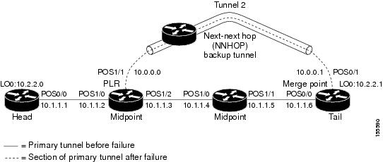
 Feedback