The documentation set for this product strives to use bias-free language. For the purposes of this documentation set, bias-free is defined as language that does not imply discrimination based on age, disability, gender, racial identity, ethnic identity, sexual orientation, socioeconomic status, and intersectionality. Exceptions may be present in the documentation due to language that is hardcoded in the user interfaces of the product software, language used based on RFP documentation, or language that is used by a referenced third-party product. Learn more about how Cisco is using Inclusive Language.
To preauthenticate calls on the basis of the Calling Line IDentification (CLID) number, use the clid command in AAA preauthentication configuration mode. To remove the clid command from your configuration, use the no form of this command.
(Optional) Implies that if the switch provides the data, RADIUS must be reachable and must accept the string in order for
preauthentication to pass. If the switch does not provide the data, preauthentication passes.
required
(Optional) Implies that the switch must provide the associated data, that RADIUS must be reachable, and that RADIUS must accept
the string in order for preauthentication to pass. If these three conditions are not met, preauthentication fails.
accept-stop
(Optional) Prevents subsequent preauthentication elements such as ctype or dnis from being tried once preauthentication has
succeeded for a call element.
passwordpassword
(Optional) Defines the password for the preauthentication element. The default password string is cisco.
Command Default
The if-avail and required keywords are mutually exclusive. If the if-avail keyword is not configured, the preauthentication setting defaults to required.
Command Modes
AAA preauthentication configuration
Command History
Release
Modification
12.1(2)T
This command was introduced.
Usage Guidelines
You may configure more than one of the authentication, authorization and accounting (AAA) preauthentication commands (clid, ctype, dnis) to set conditions for preauthentication. The sequence of the command configuration decides the sequence of the preauthentication
conditions. For example, if you configure dnis, then clid, then ctype, in this order, then this is the order of the conditions considered in the preauthentication process.
In addition to using the preauthentication commands to configure preauthentication on the Cisco router, you must set up the
preauthentication profiles on the RADIUS server.
Examples
The following example specifies that incoming calls be preauthenticated on the basis of the CLID number:
aaa preauth
 group radius
 clid required
Related Commands
Command
Description
ctype
Preauthenticates calls on the basis of the call type.
dnis(RADIUS)
Preauthenticates calls on the basis of the DNIS number.
dnisbypass(AAApreauthenticationconfiguration)
Specifies a group of DNIS numbers that will be bypassed for preauthentication.
group(RADIUS)
Specifies the AAA RADIUS server group to use for preauthentication.
clid (dial peer)
To control the presentation and use of calling-line ID (CLID) information, use the
clid command in dial peer configuration mode. To remove CLID controls, use the
no form of this command.
Network number. Establishes the calling-party network number in the CLID for this router.
network-provided
Allows you to set the screening indicator to reflect the number that was provided by the network.
overriderdnis
Supported for POTS dial peers only Overrides the CLID with the redirected dialed number identification service (RDNIS) if
available.
pi-restrict
Restricted progress indicator (PI). Causes removal of the calling-party number from the CLID when the PI is restricted.
restrict
Restricts presentation of the caller ID in the CLID.
second-numberstrip
(Optional) Removes a previously configured second network number from the CLID.
strip
Strips the calling-party number from the CLID.
name--(Optional) Calling-party name. Causes removal of the calling-party name from the CLID.
pi-restrict[all]--(Optional) Restricted PI. Causes removal of all calling-party names and numbers from the CLID when the PI is restricted.
substitutename
Copies the calling number into the display name if PI allows it (and the calling name is empty).
Command Default
No default behavior or values
Command Modes
Dial Peer configuration (config-dial-peer)
Command History
Release
Modification
12.2(11)T
This command was introduced.
12.2(13)T
The
overriderdnis keywords were added.
12.4(4)T
The following keywords were added:
network-provided,
pi-restrictall, and
substitutename.
Usage Guidelines
The
overriderdnis keywords are supported only for POTS dial peers.
CLID is the collection of information about the billing telephone number from which a call originated. The CLID value might
be the entire phone number, the area code, or the area code plus the local exchange. It is also known as caller ID. The various
keywords to this command manage the presentation, restriction, or stripping of the various CLID elements.
The
clidnetwork-number command sets the presentation indicator to "y" and the screening indicator to "network-provided." The
second-numberstrip keyword strips from the H.225 source-address field the original calling-party number, and is valid only if a network number
was previously configured.
The
clidoverriderdnis command overrides the CLID with the RDNIS if it is available.
The
clidrestrict command causes the calling-party number to be present in the information element, but the presentation indicator is set to
"n" to prevent its presentation to the called party.
The
clidstrip command causes the calling-party number to be null in the information element, and the presentation indicator is set to "n"
to prevent its presentation to the called party.
Examples
The following example sets the calling-party network number to 98765 for POTS dial peer 4321:
An alternative method of accomplishing this result is to enter the
second-numberstrip keywords as part of the
clidnetwork-number command. The following example sets the calling-party network number to 56789 for VoIP dial peer 1234 and also prevents the
second network number from being sent:
The following example overrides the calling-party number with RDNIS if available:
Router(config-dial-peer)# clid override rdnis
The following example prevents the calling-party number from being presented:
Router(config-dial-peer)# clid restrict
The following example removes the calling-party number from the CLID information and prevents the calling-party number from
being presented:
Router(config-dial-peer)# clid strip
The following example strips the name from the CLID information and prevents the name from being presented:
Router(config-dial-peer)# clid strip name
The following example strips the calling party number when PI is set to restrict clid strip from the CLID information and
prevents the calling party number from being presented:
Router(config-dial-peer)# clid strip pi-restrict
The following example strips calling party name and number when the PI is set to the restrict all clid strip from the CLID
information and prevents the calling party name and number from being presented:
Router(config-dial-peer)# clid strip pi-restrict all
The following example substitutes the calling party number into the display name:
Router(config-dial-peer)# clid substitute name
The following example allows you to set the screening indicator to reflect that the number was provided by the network:
Router(config-dial-peer)# clid network-provided
Related Commands
Command
Description
clid(voice-service-voip)
Passes the network provided ISDN numbers in an ISDN calling party information element screening indicator field, removes
the calling party name and number from the calling-line identifier in voice service voip configuration mode, or allows a presentation
of the calling number by substituting for the missing Display Name field in the Remote-Party-ID and From headers.
clid (voice service voip)
To pass the network-provided ISDN numbers in an ISDN calling party information element screening indicator field, and remove
the calling party name and number from the calling-line identifier in voice service voip configuration mode, or allow a presentation
of the calling number by substituting for the missing Display Name field in the Remote-Party-ID and From headers use the clid command in voice service voip configuration mode. To return to the default configuration, use the no form of this command.
Removes the CLID when the progress indicator (PI) is restricted for PSTN to SIP operations and removes the calling party name
and number when the PI is restricted for PSTN to SIP operations.
substitutename
Copies the calling number to the display name if unavailable for PSTN to SIP operations.
Command Default
The clid command passes along user-provided ISDN numbers in an ISDN calling party information element screening indicator field.
Command Modes
Voice service VoIP configuration (config-voi-srv)
Command History
Release
Modification
12.4(4)T
This command was introduced.
Cisco IOS XE Cupertino 17.7.1a
Introduced support for YANG models.
Usage Guidelines
Use the clidnetwork-provided keyword to pass along network-provided ISDN numbers in an ISDN calling party information element screening indicator field.
Use the clidstrippi-restrictall keyword to remove the Calling Party Name and Calling Party Number from the CLID.
Use the clidsubstitutename keyword to allow a presentation of the Display Name field in the Remote-Party-ID and From headers. The Calling Number is
substituted for the Display Name field.
Examples
The following example passes along network-provided ISDN numbers in an ISDN calling party information element screening indicator
field:
Router(conf-voi-serv)# clid network-provided
The following example passes along user-provided ISDN numbers in an ISDN calling party information element screening indicator
field:
Router(conf-voi-serv)# no clid network-provided
The following example removes the calling party name and number from the calling-line identifier (CLID):
Router(conf-voi-serv)# clid strip pi-restrict all
The following example does not remove the calling party name and number from the CLID:
Router(conf-voi-serv)# no clid strip pi-restrict all
The following example allows the presentation of the calling number to be substituted for the missing Display Name field in
the Remote-Party-ID and From headers:
Router(conf-voi-serv)# clid substitute name
The following example disallows the presentation of the calling number to be substituted for the missing Display Name field
in the Remote-Party-ID and From headers:
Router(conf-voi-serv)# no clid substitute name
Related Commands
Command
Description
clid(dial-peer)
Controls the presentation and use of CLID information in dial peer configuration mode.
clid strip
To remove the calling-party number from calling-line-ID (CLID) information and to prevent the calling-party number from being
presented to the called party, use the
clidstrip command in dial-peer configuration mode. To remove the restriction, use the
no form of this command.
clidstrip [name]
noclidstrip [name]
Syntax Description
name
(Optional) Removes the calling-party name for both incoming and outgoing calls.
Command Default
Calling-party number and name are included in the CLID information.
Command Modes
Dial-peer configuration (config-dial-peer)
Command History
Cisco IOS Release
Cisco CME Version
Modification
12.2(11)T
2.01
This command was introduced.
12.2(15)ZJ1
3.0
This command was modified. The
name keyword was added.
12.3(4)T
3.0
This command was integrated into Cisco IOS Release 12.3(4)T.
Usage Guidelines
If the
clidstrip command is issued, the calling-party number is null in the information element, and the presentation indicator is set to
"n" to prevent the presentation of the number to the called party.
If you want to remove both the number and the name, you must issue the command twice, once with the
name keyword.
Examples
The following example removes the calling-party number from the CLID information and prevents the calling-party number from
being presented:
Router(config-dial-peer)# clid strip
The following example removes both the calling-party number and the calling-party name from the caller-ID display:
Router(config-dial-peer)# clid strip
Router(config-dial-peer)# clid strip name
Related Commands
Command
Description
clidnetwork-number
Configures a network number in the router for CLID and uses it as the calling-party number.
clidrestrict
Prevents the calling-party number from being presented by CLID.
clidsecond-numberstrip
Prevents the second network number from being sent in the CLID information.
clid strip reason
To remove the calling-line ID (CLID) reason code and to prevent it from being displayed on the phone, use the clidstripreason command in dial peer voice configuration mode. To disable the configuration, use the no form of this command.
clidstripreason
noclidstripreason
Syntax Description
This command has no arguments or keywords.
Command Default
The CLID reason code is not removed.
Command Modes
Dial peer voice configuration (config-dial-peer)
Command History
Release
Modification
12.4(15)T
This command was introduced.
Usage Guidelines
When the caller-idenablecommand is enabled on the gateway so that the gateway forwards information depending on the preference of the caller, client
layer interface port (CLIP), or calling line identification restriction (CLIR), an "unavailable" message is displayed on the
terminating phone. An "unavailable" message is a standard message that indicates the reason for the absence of calling party
name.
You can use the clidstripreason command to remove the message and have only the call parameters forwarded.
Examples
The following example shows how to remove the CLID reason code:
Allows the sending or receiving of caller-ID information.
clidstrip
Removes the calling-party number from CLID information and prevents the calling-party number from being presented to the called
party.
dial-peervoice
Defines a particular dial peer, specifies the method of voice encapsulation, and enters dial peer configuration mode.
client-vtp (voice class)
To configure a client verification trustpoint, and associate it to a TLS profile, use
the command client-vtp in voice class configuration mode.
To delete the client verification trustpoint, use no form
of this command.
client-vtp verification trustpoint
no client-vtp
Syntax Description
verification trustpoint
Assigns a client verification trustpoint.
Command Default
No default behavior or values
Command Modes
Voice class configuration (config-class)
Command History
Release
Modification
Cisco IOS XE Amsterdam 17.3.1a
This command was introduced under voice class configuration
mode.
Usage Guidelines
The client verification truspoint is associated to a TLS profile through the command
voice class tls-profile tag. The
tag associates the client verification trustpoint
configuration to the command crypto signaling.
Examples
The following example illustrates how to create a voice class tls-profile and
associate a client verification trustpoint:
Router(config)#voice class tls-profile 2
Router(config-class)#client-vtp TPname
Related Commands
Command
Description
voice class tls-profile
Provides sub-options to configure the commands that are required
for a TLS session.
crypto signaling
Identifies the trustpoint or the tls-profiletag that is used during the TLS handshake
process.
clock-rate (codec-profile)
To set the clock rate, in Hz, for the codec, use the clock-rate command in codec-profile configuration mode. To return to the default value, use the no form of this command.
Defines video capabilities needed for video endpoints.
clock-select
To establish the sources and priorities of the requisite clocking
signals for the OC-3/STM-1 ATM Circuit Emulation Service network module, use
the
clock-select
command in CES configuration mode.
clock-select priority-number
interface slot/port
Syntax Description
priority-number
Priority of the clock source. Range is from 1 (high
priority) to 4 (low priority). There is no default value.
interface
Specifies the interface to supply the clock source.
slot/port
Backplane slot number and port number on the interface.
Command Default
No default behavior or values
Command Modes
CES configuration (config-ces)
Command History
Release
Modification
12.1(2)T
This command was introduced on the Cisco 3600 series.
Usage Guidelines
This command is used on Cisco 3600 series routers that have
OC-3/STM-1 ATM CES network modules.
To support synchronous or synchronous residual time stamp (SRTS)
clocking modes, you must specify a primary reference source to synchronize the
flow of constant bit rate (CBR) data from its source to its destination.
You can specify up to four clock priorities. The highest priority
active interface in the router supplies primary reference source to all other
interfaces that require network clock synchronization services. The fifth
priority is the local oscillator on the network module.
Use the
showcesclock-selectcommand to display the currently configured clock priorities on
the router.
Examples
The following example defines two clock priorities on the router:
clock-select 1 cbr 2/0
clock-select 2 atm 2/0
Related Commands
Command
Description
channel-group
Configures the timing recovery clock for the CES interface.
clocksource
Configures a transmit clock source for the CES interface.
showcesclock
Displays which ports are designated as network clock
sources.
cm-current-enhance
To improve immunity to extreme levels of longitudinal noise present in wiring that includes long cable lengths, use the
cm-current-enhance command in Voice-port configuration mode. To return to the default configuration, use the
no form of this command.
cm- current- enhance
nocm- current- enhance
Syntax Description
This command has no arguments or keywords.
Command Default
The
cm-current-enhance command is not configured.
Command Modes
Voice-port configuration (config-voiceport)
Command History
Release
Modification
15.2(1)T
This command was introduced.
Usage Guidelines
This command should not be used under normal conditions. It should be used only to improve immunity to noise in cases of extreme
levels of longitudinal noise on the wiring.
The command is available on the following platforms, in the modes indicated:
VIC3-2FXS-E/DID (FXS and DID mode)
VIC3-2FXS/DID, VIC3-4FXS/DID, and EM3-HDA-8FXS/DID (DID mode only)
Mode of action: When the cm-current-enhance mode is activated, REG 73 of the Silab chip (Si324x) is programmed to 1 to enhance
the immunity to common-mode current noise.
Change of signaling type: The command is effective for the current signaling type value. The command state is not saved and
applied after a change of signaling type.
Examples
The following example indicates the usage:
Device# config t
Enter configuration commands, one per line.  End with CNTL/Z.
Device(config)# voice-port 0/1/0
Device(config-voiceport)# cm-current-enhance
cn-san validate (voice class tls-profile)
To enable server, client, or bidirectional identity validation of a peer certificate during TLS handshake, use the command cn-sanvalidate in voice class tls-profile configuration mode. To disable certificate identity validation, use no form of this command.
cn-sanvalidate {server| client | bidirectional}
no cn-san
Syntax Description
validate server
Enables server identity validation through Common Name (CN) and
Subject Alternate Name (SAN) fields in the server certificate
during client-side SIP/TLS connections.
validate client
Enables client identity validation through CN and SAN fields in the client certificate during server side SIP/TLS connections.
validate bidirectional
Enables both client and server identity validation through CN-SAN fields.
Command Default
Identity validation is disabled.
Command Modes
Voice class configuration (config-class)
Command History
Release
Modification
Cisco IOS XE Cupertino
17.8.1a
client and bidirectional options were introduced under voice class tls-profile configuration mode.
Cisco IOS XE Amsterdam 17.3.1a
validate server command was introduced under voice class tls-profile configuration mode.
Introduced support for YANG Model.
Usage Guidelines
Server identity validation is associated with a secure signaling connection through the global crypto signaling and voice class tls-profileconfigurations.
From Cisco IOS XE Amsterdam 17.3.1a release, cn-sanvalidate serverallows a server certificate to be validated while establishing a SIP TLS connection. For this validation, CUBE checks that the domain name configured in the session target matches one of the names included in either the CN or SAN fields.
The session is established only if these match.
From Cisco IOS XE Cupertino
17.8.1a release, the command is enhanced to include the client and biderectional keywords. The client option allows a server to validate the identity of a client by checking CN and SAN hostnames included
in the provided certificate against a trusted list of cn-san FQDNs. The connection will only be established if a match is
found. This list of cn-san FQDNs is also now used to validate a server certificate, in addition to the session target host
name. The biderectional option validates peer identity for both client and server connections by combining both server and client modes. Once you configure cn-san validate, the identity of the peer certificate is validated for every new TLS connection.
Examples
From Cisco IOS XE Cupertino
17.8.1a onwards, the voice class tls-profiletag can be associated to a voice-class tenant also. For CN-SAN validation of the client certificate, define a list of allowed hostnames and patterns using the command
cn-santagsan-name.
Examples
The following example illustrates how to configure a voice class tls-profile and associate server identity validation functionality:
Router(config)#voice class tls-profile 2
Router(config-class)#cn-san validate server
Router(config)#voice class tls-profile 3
Router(config-class)#cn-san validate client
Router(config)#voice class tls-profile 4
Router(config-class)#cn-san validate bidirectional
Related Commands
Command
Description
voice classtls-profile
Provides suboptions to configure the commands that are required for a TLS session.
cn-santagsan-name
List of CN-SAN names used to validate the peer certificate for inbound or outbound TLS connections.
cn-san (voice class tls-profile)
To configure a list of Fully Qualified Domain Names (FQDN) names to validate against the peer certificate for inbound or
outbound TLS connections, use the cn-san command in voice class tls-profile configuration mode.
For inbound connections, the list is used to validate CN and SAN fields in the client certificate. For outbound connections,
the list is used along with the session target hostname to validate CN and SAN fields in the server certificate.
To delete a certificate validation cn-san entry, use the no form of this command.
cn-san{1-10} fqdn
nocn-san{1-10}fqdn
Syntax Description
1-10
Specifies the tag of cn-san FQDN list entry.
fqdn
Specifies the FQDN or a domain wildcard in the form of *.domain-name.
Command Default
no cn-san names are configured.
Command Modes
Voice class tls-profile configuration mode
Command History
Release
Modification
Cisco IOS XE Cupertino
17.8.1a
This command is introduced.
Usage Guidelines
FQDN used for peer certificate validation are assigned to a TLS profile with up to ten cn-san entries. At least one of these entries must be matched to an FQDN in either of the certificate Common Name (CN) or Subject-Alternate-Name
(SAN) fields before a TLS connection is established. To match any domain host used in an CN or SAN field, a cn-san entry may be configured with a domain wildcard, strictly in the form *.domain-name (e.g. *.cisco.com). No other use of wildcards
is permitted.
Note
Server certificates may also be verified by matching the SIP session target FQDN to a CN or SAN field.
Examples
The following example globally enables cn-san names:
Router(config)# voice class tls-profile 1
Router(config-class)# cn-san 2 *.webex.com
Related Commands
Command
Description
voice class tls-profile
Provides suboptions to configure the commands that are required for a TLS session.
codec (dial peer)
To specify the voice coder rate of speech for a dial peer, use the codec command in dial peer configuration mode. To reset command settings to the default value, use the no form of this command.
Specifies the voice coder rate for speech. Codec options available for various platforms are described in the following (first)
table.
bytes
(Optional) Precedes the argument that specifies the number of bytes in the voice payload of each frame.
payload-size
(Optional) Number of bytes in the voice payload of each frame. See the second table below for valid entries and default values.
transparent
Enables codec capabilities to be passed transparently between endpoints in a Cisco Unified Border Element.
Note
The
transparent keyword is available only on the Cisco 2600, 3600, 7200, and 7500 series router platforms.
fixed-bytes
(Optional) Indicates that the codec byte size is fixed and nonnegotiable.
mode
(Optional) For Cisco internet Speech Audio Codec (iSAC) codec only. Specifies the iSAC operating frame mode that is encapsulated
in each packet.
independent
(Optional) For iSAC codec only. Specifies that the configuration mode variable bit rate is independent (value 1).
adaptive
(Optional) For iSAC codec only. Specifies that the configuration mode variable bit rate is adaptive (value 0).
bitratevalue
(Optional) For iSAC codec only. Configures the target bit rate in kilobits per second. Range is 10–32.
frame-size
(Optional) For iSAC codec only. Specifies the operating frame in milliseconds (ms). Valid entries are:
30--30-ms frames
60--60-ms frames
fixed--This keyword is applicable only for adaptive mode.
profile
(Optional) Defines the profile that is associated with the codec.
tag
(Optional) Specifies the codec profile tag that is associated with the codec. Range: 1–1000000.
Command Default
g729r8, 30-byte payload for Voice over Frame Relay (VoFR) and Voice over ATM (VoATM). g729r8, 20-byte payload for Voice over
IP (VoIP). See the second table for valid entries and default values for codecs.
Command Modes
Dial peer configuration (config-dial-peer)
Command History
Release
Modification
11.3(1)T
This command was introduced on the Cisco 3600 series.
11.3(3)T
This command was implemented on the Cisco 2600 series.
12.0(3)T
This command was implemented on the Cisco AS5300. This release does not support the
clear-channel keyword.
12.0(4)T
This command was implemented on the Cisco 3600 series, Cisco 7200 series, and Cisco MC3810, and the command was modified
for VoFR dial peers.
12.0(5)XE
More codec choices and other options were implemented.
12.0(5)XK
The
g729br8 and
pre-ietf codec keywords were added for the Cisco 2600 and Cisco 3600 series.
12.0(7)T
This command was integrated into Cisco IOS Release 12.0.(7)T and implemented on the Cisco AS5800. Voice coder rates of speech
were added. This release does not support the
clear-channel keyword, so it is no longer available in the command syntax.
12.0(7)XK
The g729abr8 and g729ar8 codec keywords were added for the Cisco MC3810, and the pre-ietf keyword was deleted.
12.1(1)T
This command was integrated in Cisco IOS Release 12.1(1)T.
12.1(5)T
The gsmefr and gsmfr codec keywords were added.
12.2(8)T
The command was implemented on the Cisco 1750 and Cisco 1751.
12.2(13)T3
The
transparent keyword was added for use with H.323 to H.323 connections. This keyword is available only in js2 images.
12.4(11)XJ2
The gsmefr and gsmfrkeywords were removed as configurable codec options for all platforms except the gsmfr codec on the Cisco AS5400 and AS5350 with MSAv6 DSPs. The transparent keyword now supports H.323 to SIP connections.
12.4(15)T
This command was integrated into Cisco IOS Release 12.4(15)T.
12.4(15)XY
The
g722-64 keyword was added.
12.4(20)T
This command was integrated into Cisco IOS Release 12.4(20)T.
15.0(1)M
The
fixed-bytes keyword was added.
15.1(1)T
This command was modified. The isac keyword was added as a codec type, and the mode, independent, adaptive, bitrate, and fixed keywords were added as configurable parameters.
Cisco IOS XE Amsterdam 17.3.1a
The command was modified to support Opus codec in Cisco Unified Border Element. The keyword profile and the variable tag were added as configurable parameters for Opus codec.
Cisco IOS XE Cupertino 17.7.1a
Introduced support for YANG models.
Usage Guidelines
Note
In YANG, only codec transparent can be configured under dial-peer. For all other codec configurations, use 'voice class codec' configuration.
Use this command to define a specific voice coder rate of speech and payload size for a VoIP or VoFR dial peer. This command
is also used for VoATM.
A specific codec type can be configured on the dial peer as long as the codec is supported by the setting that is used with
the codec complexity voice-card configuration command. The codec complexity command is voice-card specific and platform specific. The codec complexity voice-card configuration command is set to either high or medium.
If the codec complexity command is set to high, the following keywords are available: g711alaw, g711ulaw, g722-64, g723ar53, g723ar63, g723r53, g723r63, g726r16, g726r24, g726r32, g728, g729r8, and g729br8.
If the codec complexity command is set to medium, the following keywords are available: g711alaw, g711ulaw, g726r16, g726r24, g726r32, g729r8, and g729br8.
The codec dial peer configuration command is useful when you must change to a small-bandwidth codec. Large-bandwidth codecs, such as
G.711, do not fit in a small-bandwidth link. However, the g711alaw and g711ulaw codecs provide higher quality voice transmission
than other codecs. The g729r8 codec provides near-toll quality with considerable bandwidth savings.
The
transparent keyword is available with H.323 to H.323 call connections beginning in Cisco IOS Release 12.2(13)T3. Support for the keyword
in H.32 to SIP call connections begins in Cisco IOS Release 12.4(11)XJ2.
If codec values for the dial peers of a connection do not match, the call fails.
You can change the payload of each VoIP frame by using the bytes keyword; you can change the payload of each VoFR frame by using the bytes keyword with the payload-size argument. However, increasing the payload size can add processing delay for each voice packet.
The table below describes the voice payload options and default values for the codecs and packet voice protocols.
Table 1. Voice Payload-per-Frame Options and Defaults
Codec
Protocol
Voice Payload Options (in Bytes)
Default Voice Payload (in Bytes)
g711alaw g711ulaw
VoIP VoFR VoATM
80, 160 40 to 240 in multiples of 40 40 to 240 in multiples of 40
160 240 240
g722-64
VoIP
80, 160, 240
160
g723ar53 g723r53
VoIP VoFR VoATM
20–220 in multiples of 20 20 to 240 in multiples of 20 20 to 240 in multiples of 20
20 20 20
g723ar63 g723r63
VoIP VoFR VoATM
24 to 216 in multiples of 24 24 to 240 in multiples of 24 24 to 240 in multiples of 24
24 24 24
g726r16
VoIP VoFR VoATM
20 to 220 in multiples of 20 10 to 240 in multiples of 10 10 to 240 in multiples of 10
40 60 60
g726r24
VoIP VoFR VoATM
30–210 in multiples of 30 15 to 240 in multiples of 15 30 to 240 in multiples of 15
60 90 90
g726r32
VoIP VoFR VoATM
40–200 in multiples of 40 20 to 240 in multiples of 20 40 to 240 in multiples of 20
80 120 120
g728
VoIP VoFR VoATM
10 to 230 in multiples of 10 10 to 240 in multiples of 10 10 to 240 in multiples of 10
40 60 60
g729abr8 g729ar8 g729br8 g729r8
VoIP VoFR VoATM
10 to 230 in multiples of 10 10 to 240 in multiples of 10 10 to 240 in multiples of 10
20 30 30
isac
VoIP
10 to 230 in multiples of 10
30 60
Note
If you are configuring G.729r8 or G.723 as the
codec-type, the maximum value for the
payload-size argument is 60 bytes.
For toll quality, use the
g711alaw or
g711ulawkeyword. These values provide high-quality voice transmission but use a significant amount of bandwidth. For nearly toll quality
(and a significant savings in bandwidth), use the
g729r8keyword.
Note
The G.723 and G.728 codecs are not supported on the Cisco 1700 platform for Cisco Hoot and Holler applications.
Note
The
clear-channel keyword is not supported on the Cisco AS5300.
Note
The G.722-64 codec is supported only for H.323 and SIP.
Examples
The following example shows how to configure a voice coder rate that provides toll quality voice with a payload of 120 bytes
per voice frame on a router that acts as a terminating node. The sample configuration begins in global configuration mode
and is for VoFR dial peer 200.
dial-peer voice 200 vofr
 codec g711ulaw bytes 240
Examples
The following example shows how to configure a voice coder rate for VoIP dial peer 10 that provides toll quality but uses
a relatively high amount of bandwidth:
dial-peer voice 10 voip
 codec g711alaw
Examples
The following example shows how to configure the transparent codec used by the Cisco Unified Border Element:
Specifies call density and codec complexity based on the codec used.
showdialpeervoice
Displays the codec setting for dial peers.
codec (dsp)
To specify call density and codec complexity based on a particular codec standard, use the codec command in DSP interface DSP farm configuration mode. To reset the card type to the default, use the no form of the command.
codec {high | med}
nocodec {high | med}
Syntax Description
high
Specifies high complexity: two channels of any mix of codec.
med
Specifies medium complexity: four channels of g711/g726/g729a/fax.
Command Default
Medium complexity
Command Modes
DSP interface DSP farm
Command History
Release
Modification
12.0(5)XE
This command was introduced on the Cisco 7200 series.
12.1(1)T
This command was integrated into Cisco Release 12.1(1)T.
12.1(3)T
This command was implemented on the Cisco 7500 series.
Usage Guidelines
This command is supported on only the Cisco 7200 series and Cisco 7500 series routers.
Codec complexity refers to the amount of processing required to perform compression. Codec complexity affects the number of
calls, referred to as call density, that can take place on the DSPfarm interfaces. The greater the codec complexity, the fewer
the calls that are handled. For example, G.711 requires less DSP processing than G.728, so as long as the bandwidth is available,
more calls can be handled simultaneously by using the G.711 standard than by using G.728.
The DSPinterface dspfarm codec complexity setting affects the options available for the codecdialpeerconfiguration command.
To change codec complexity, you must first remove any configured-channel associated signaling (CAS) or DS0 groups and then
reinstate them after the change.
Note
On the Cisco 2600 series routers, and 3600 series codec-complexity is configured using the codeccomplexity command in voice-card configuration mode.
Examples
The following example configures the DSPfarm interface 1/0 on the Cisco 7200 series routers to support high compression:
dspint DSPFarm 1/0
 codec high
Related Commands
Command
Description
codec(dialpeer)
Specifies the voice codec rate of speech for a dial peer.
codeccomplexity
Specifies call density and codec complexity based on the codec standard you are using.
codec (DSP farm profile)
To specify the codecs that are supported by a digital signal processor (DSP) farm profile, use the
codec command in DSP farm profile configuration mode. To remove the codec, use the
no form of this command.
g711alaw--G.711 a-law 64,000 bits per second (bps)
g711ulaw--G.711 mu-law 64,000 bps
g722r-64--G.722-64 at 64,000 bps
g729abr8--G.729 ANNEX A and B 8000 bps
g729ar8--G.729 ANNEX A 8000 bps
g729br8--G.729 ANNEX B 8000 bps
g729r8--G.729 8000 bps
h263--H.263 video codec
h264--H.264 video codec
ilbc--Internet Low Bitrate Codec (iLBC)
isac--Cisco internet Speech Audio Codec (iSAC) codec
resolution
Specifies the supported video resolution. The valid entries are:
For H.263--qcifandcif
For H.264--qcif,
cif,
vga,
w360p,
w448p,
4cif, and
720p
Note
720p option applies only to homogeneous video conferences.
frame-rateframerate
Specifies the frame rate. The valid entries are 15 fps or 30 fps.
This option applies to homogeneous conferences only.
bitratebitrate
Specifies the bitrate.
This option applies to homogeneous conferences only.
rfc-2190
Specifies the payload format follow RFC-2190.
pass-through
Enables codec pass-through. Supported for transcoding and media termination point (MTP) profiles.
Transcoding
The following transcoding default apply when you are configuring audio profiles only. When you configure video transcoding,
you must specify the audio codecs.
The
gsmefrand
gsmfrkeywords were removed as configurable codec options for all platforms.
12.4(15)T
This command was integrated into Cisco IOS Release 12.4(15)T.
12.4(15)XY
The
g722r-64 keyword was added.
12.4(20)T
This command was integrated into Cisco IOS Release 12.4(20)T.
12.4(22)T
Support for IPv6 was added.
15.1(1))T
This command was modified. The
isac keyword was added.
15.1(4)M
This command was modified. The
frame-rate,
bitrate,
rfc-2190, and
pass-throughkeywords were added and codec support was added for
ilbc,
h.263and
h.264.
Usage Guidelines
Only one codec is supported for each MTP profile. To support multiple codecs, you must define a separate MTP profile for
each codec.
For homogeneous video profiles, only one video format is supported
For heterogeneous and heterogeneous guaranteed-audio video profiles, multiple video formats and audio codecs are supported.
To change the configured codec in the profile, you must first enter a
nomaximumsessioncommand.
The table below shows the relationship between DSP farm functions and codecs.
Table 2. DSP Farm Functions and Codec Relationships
DSP Farm Function
Supported Codec
Transcoding
g711alaw
g711ulaw
g729abr8
g729ar8
iSAC
h263
h264
Conferencing
g711alaw
g711ulaw
g722r-64
g729abr8
g729ar8
g729br8
g729r8
h263
h264
ilbc
MTP
g711ulaw
iSAC
Hardware MTPs support only G.711 a-law and G.711 mu-law. If you configure a profile as a hardware MTP and you want to change
the codec to other than G.711, you must first remove the hardware MTP by using thenomaximumsessionshardware command.
The
pass-through keyword is supported for transcoding and MTP profiles only; the keyword is not supported for conferencing profiles. To support
the Resource Reservation Protocol (RSVP) agent on a Skinny Client Control Protocol (SCCP) device, you must use the
codecpass-through command. In the pass-through mode, the SCCP device processes the media stream by using a pure software MTP, regardless of
the nature of the stream, which enables video and data streams to be processed in addition to audio streams. When the pass-through
mode is set in a transcoding profile, no transcoding is done for the session; the transcoding device performs a pure software
MTP function. The pass-through mode can be used for secure Real-Time Transport Protocol (RTP) sessions.
Examples
The following example shows how to set the call density and codec complexity to g729abr8:
Router(config)# dspfarm profile 123 transcode
Router(config-dspfarm-profile)# codec g729abr8
The following example shows how to set up a video conference with guaranteed-audio.
Router(config)# dspfarm profile 99 conference video guaranteed-audio
Router(config-dspfarm-profile)# codec h264 4cif
Router(config-dspfarm-profile)# codec h264 cif
Router(config-dspfarm-profile)# maximum conference-participants 8
Related Commands
Command
Description
associateapplication
Associates the SCCP protocol to the DSP farm profile.
dspfarmprofile
Enters DSP farm profile configuration mode and defines a profile for DSP farm services.
maximumsessions(DSPFarmprofile)
Specifies the maximum number of sessions that are supported by the profile.
rsvp
Enables RSVP support on a transcoding or MTP device.
maximumconference-participants(DSPFarmprofile)
Specifies the maximum number of conference participants that are supported by this profile.
shutdown(DSPFarmprofile)
Disables a DSP farm profile.
codec (voice-card)
To specify call density and codec complexity according to the codec standard that is being used or to increase processing
frequency for the G.711 codec, use the
codeccommand in voice-card configuration mode. To reset the flex complexity default or to disable configured values, use the no
form of this command.
codec {complexity {flex [reservation-fixed {high | medium}] | high | medium | secure} | sub-sample}
nocodeccomplexity
Syntax Description
complexity
Manages the complexity and density of codecs used in voice processing.
flex
When the
flex keyword is used, up to 16 calls can be completed per digital signal processor (DSP). The number of supported calls varies
from 6 to 16, depending on the codec used for a call. In this mode, reservation for analog voice interface cards (VICs) may
be needed for certain applications such as Central Automatic Message Accounting (CAMA) E-911 calls because oversubscription
of DSPs is possible. If this is true, enable the
reservation-fixed keyword. There is no reservation by default.
reservation-fixed
(Optional) If you have specified the
flex keyword, the
reservation-fixed keyword ensures that sufficient DSP resources are available to handle a call. If you enter the
reservation-fixed keyword, set the complexity for
high or
medium. (See the guidelines following to understand the effects of the keywords.) This option appears only when there is an analog
VIC present.
high
If you specify the
high keyword to define the complexity, each DSP supports two voice channels encoded in any of the following formats:
If you specify the
securekeyword to define complexity, each DSP on an NM-HDV network module supports two voice channels encoded in any of the following
formats:
g711alaw--G.711 a-law 64,000 bps.
g711ulaw--G.711 mu-law 64,000 bps.
g729--G.729 8000 bps.
g729A--G.729 8000 bps.
sub-sample
Increases the processing frequency for the G.711 codec with reduced 5510 DSP density.
Command Default
The default type of codec complexity is
flex. The default value for the G.711 codec is 10 milliseconds (ms).
Command Modes
Voice-card configuration (config-voice-card)
Command History
Release
Modification
12.0(5)XK
This command was introduced as the codec complexity on the Cisco 2600 and Cisco 3600 series.
12.0(7)T
This command was integrated into Cisco IOS Release 12.0(7)T.
12.0(7)XK
This command was implemented on the Cisco MC3810 for use with the high-performance compression module (HCM).
12.1(2)T
This command was integrated into Cisco IOS Release 12.1(2)T.
12.2(8)T
This command was implemented on the Cisco 1750 and Cisco 1751.
12.2(13)T
The
ecan-extendedkeyword was added.
12.2(15)T
This command was integrated into Cisco IOS Release 12.2(15)T with support for the Cisco 2600 series, Cisco 2600XM, Cisco
3660, Cisco 3725, and Cisco 3745 routers. High codec complexity is supported for DSP processing on these platforms.
12.2(15)ZJ
This command was integrated into Cisco IOS Release 12.2(15)ZJ and the
flex keyword was added. The
ecan-extended keyword was removed and G.168 echo-cancellation compliance became the default.
12.3(4)T
This command was integrated into Cisco IOS Release 12.3(4)T.
12.3(7)T
This command was integrated into Cisco IOS Release 12.3(7)T and the
reservation-fixed keyword was added.
12.3(14)T
This command was integrated into Cisco IOS Release 12.3(14)T and the
secure keyword was added to provide secure codec complexity for TI-549 DSP processing on the NM-HDV network module.
12.4(22)T1
The
codeccomplexity command was changed to the
codec(voice-card) command and the
sub-sample keyword was added for the 5510 DSP.
Usage Guidelines
Codec complexity refers to the amount of processing required to perform voice compression. Codec complexity affects the call
density--the number of calls reconciled on the DSPs. With higher codec complexity, fewer calls can be handled. Select a higher
codec complexity if that is required to support a particular codec or combination of codecs. Select a lower codec complexity
to support the greatest number of voice channels, provided that the lower complexity is compatible with the particular codecs
in use.
For codec complexity to change, all of the DSP voice channels must be in the idle state.
When you have specified the
flexkeyword, you can connect (or configure in the case of DS0 groups and PRI groups) more voice channels to the module than the
DSPs can accommodate. If all voice channels should go active simultaneously, the DSPs become oversubscribed, and calls that
are unable to allocate a DSP resource fail to connect. The
flex keyword allows the DSP to process up to 16 channels. In addition to continuing support for configuring a fixed number of
channels per DSP, theflex keyword enables the DSP to handle a flexible number of channels. The total number of supported channels varies from 6 to
16, depending on which codec is used for a call. Therefore, the channel density varies from 6 per DSP (high-complexity codec)
to 16 per DSP (g.711 codec).
The
high keyword selects a higher codec complexity if that is required to support a particular codec or combination of codecs. When
you use the
codeccomplexityhigh command to change codec complexity, the system prompts you to remove all existing DS0 or PRI groups using the specified voice
card, then all DSPs are reset, loaded with the specified firmware image, and released.
The
medium keyword selects a lower codec complexity to support the greatest number of voice channels, provided that the lower complexity
is compatible with the particular codecs in use.
The
secure keyword restricts the number of TI-549 DSP channels to 2, which is the lower codec complexity required to support Secure
Real-Time Transport Protocol (SRTP) package capability on the NM-HDV and enable media authentication and encryption. If the
secure command is not configured then the gateway will not advertise secure capability to Cisco CallManager, resulting in nonsecure
calls. You do not need to use any command to specify secure codec complexity for TI-5510 DSPs, which support SRTP capability
in all modes. Use the
mgcppackage-capabilitysrtp-packagecommand to enable MGCP gateway capability to process SRTP packages. Use the
showvoicedsp command to display codec complexity status.
Voice quality issues may occur when there are more than 15 G.711 channels on one 5510 DSP. To resolve the voice-quality issue,
change the processing period (or segment size) of the G.711 codec from 5 ms to 10 ms. (The segment size of most voice codecs
is 10 ms.) However, a voice call with 10-ms segment size has longer end-to-end delay (+ 5ms to 10 ms) than a call with 5-ms
segment size.
Beginning in Cisco IOS Release 12.4(22)T1, the
sub-sample keyword is added for applications that have strict requirements for round-trip delay times for VoIP. You can now accept the
default G.711 (10 ms with lower MIPS) or enter the
codecsub-sample command to select 5-ms G.711 (lower delay with higher MIPS). The
sub-sample keyword is enabled only for the 5510 DSP.
The
codecsub-sample command enables 5-ms processing for the G.711 codec inside the DSP to reduce the delay. However, this reduces the channel
density of G.711 channels from 16 to 14. There is no difference in secure channel density when this mode is enabled.
Examples
The following example sets the codec complexity to high on voice card 1 installed on a router, and configures local calls
to bypass the DSP:
voice-card 1
 codec complexity high
local-bypass
The following example sets the codec complexity to secure on voice card 1 installed on the NM-HDV, and configures it to support
SRTP package processing, media authentication, and encryption:
voice-card 1
 codec complexity secure
The following example shows how to enable 5-ms processing for the G.711 codec inside the 5510 DSP:
voice-card 1
 codec sub-sample
Related Commands
Command
Description
ds0-group
Defines T1/E1 channels for compressed voice calls and the CAS method by which the router connects to the PBX or PSTN.
mgcppackage-capability
Enables MGCP gateway capability to process SRTP packages.
showvoicedsp
Displays the current status of all DSP voice channels.
codec aal2-profile
To set the codec profile for a digital signal processor (DSP) on a per-call basis, use the codecaal2-profile command in dial peer configuration mode. To restore the default codec profile, use the no form of this command.
Establishes a session protocol for calls between the local and remote routers via the packet network.
codec gsmamr-nb
To specify the Global System for Mobile Adaptive Multi-Rate Narrow Band (GSMAMR-NB) codec for a dial peer, use the codecgsmamr-nbcommand in dial peer voice configuration mode. To disable the GSMAMR-NB codec, use the no form of this command.
(Optional) The eight speech-encoding modes (bit rates between 4.75 and 12.2 kbps) available in the GSMAMR-NB codec.
modes-value
(Optional) Valid values are from 0 to 7. You can specify modes as a range (for example, 0-2), or individual modes separated
by commas (for example, 2,4,6), or a combination of the two (for example, 0-2,4,6-7).
Command Default
Packetization period is 20 ms.
Encapsulation is rfc3267.
Frame format is octet-aligned.
CRC is no-crc.
Modes value is 0-7.
Command Modes
Dial peer configuration (config-dial-peer)
Command History
Release
Modification
12.4(4)XC
This command was introduced.
12.4(9)T
This command was integrated into Cisco IOS Release 12.4(9)T.
Usage Guidelines
The codecgsmamr-nb command configures the GSMAMR-NB codec and its parameters on the Cisco AS5350XM and Cisco AS5400XM platforms.
Examples
The following example sets the codec to gsmamr-nb and sets parameters:
Specifies call density and codec complexity based on the codec used.
showdialpeervoice
Displays the codec setting for dial peers.
codec ilbc
To specify the voice coder rate of speech for a dial peer using the internet Low Bandwidth Codec (iLBC), use the codecilbccommand in dial-peer configuration mode. To reset the default value, use the no form of this command.
codecilbc [modeframe_size [bytespayload_size]]
nocodecilbc [modeframe_size [bytespayload_size]]
Syntax Description
mode
(Optional) Specifies the iLBC operating frame mode that is encapsulated in each packet.
frame_size
(Optional) iLBC operating frame in milliseconds (ms). Valid entries are:
20--20ms frames for 15.2kbps bit rate
30--30ms frames for 13.33 kbps bit rate
Default is 20.
bytes
(Optional) Specifies the number of bytes in the voice payload of each frame.
payload_size
(Optional) Number of bytes in the voice payload of each frame. Valid entries are:
For mode20--38, 76, 114, 152, 190, 228. Default is 38.
For mode30--50, 100, 150, 200. Default is 50.
Command Default
20ms frames with a 15.2kbps bit rate.
Command Modes
Dial-peer configuration
Command History
Release
Modification
12.4(11)T
This command was introduced.
IOS Release XE 2.5
This command was integrated into Cisco IOS XE Release 2.5.
Usage Guidelines
Use thiscommand to define a specific voice coder rate of speech and payload size for a VoIP dial peer using an iLBC codec.
If codec values for the dial peers of a connection do not match, the call fails.
You can change the payload of each VoIP frame by using the byteskeyword. However, increasing the payload size can add processing delay for each voice packet.
Examples
The following example shows how to configure the iLBC codec on an IP-to-IP Gateway:
To specify a list of preferred codecs to use on a dial peer, use the codec preference command in voice class configuration mode. To disable this functionality, use the no form of this command.
Specifies the order of preference; Range is 1 to 24. 1 is the most preferred.
codec-type
The codec preferred. Values are as follows:
clear-channel—Clear Channel 64,000 bps.
g711alaw—G.711 a-law 64,000 bps.
g711ulaw—G.711 mu-law 64,000 bps.
g722r-64—G.722-64 at 64,000 bps.
g723ar53—G.723.1 Annex-A 5300 bps.
g723ar63—G.723.1 Annex-A 6300 bps.
g723r53—G.723.1 5300 bps.
g723r63—G.723.1 6300 bps.
g726r16—G.726 16,000 bps
g726r24—G.726 24,000 bps
g726r32—G.726 32,000 bps.
g728—G.728 16,000 bps.
g729abr8—G.729 ANNEX-A and B 8000 bps.
g729br8—G.729 ANNEX-B 8000 bps.
g729r8—G.729 8000 bps.
gsmamr-nb—Enables GSMAMR-NB codec capability.
gsmfr—Global System for Mobile Communications Full Rate (GSMFR) 13,200 bps.
Note
The gsmfr keyword is configurable only on the Cisco AS5350 and AS5400 with MSAv6 digital signal processors (DSPs).
opus—Opus upto 510 kbps.
scip—scip audio codec.
Note
In Cisco IOS XE 17.16.1a release, the Secure Communications Interoperability Protocol (SCIP) feature is available in 'preview’ mode as it includes
limited functionality or incomplete software dependencies.
ilbc—internet Low Bitrate Codec (iLBC) at 13,330 bps or 15,200 bps.
isac—Cisco internet Speech Audio Codec (iSAC) codec.
transparent—Enables codec capabilities to be passed transparently between endpoints.
Note
The transparent keyword is not supported when the call-start command is configured.
mode
(Optional) For iLBC and iSAC codecs only. Specifies the iLBC or iSAC operating frame mode that is encapsulated in each packet.
independent
(Optional) For iSAC codec only. Specifies that the configuration mode variable bit rate (VBR) is independent (value 1).
adaptive
(Optional) For iSAC codec only. Specifies that the configuration mode VBR is adaptive (value 0).
frame-size
(Optional) For iLBC and iSAC codecs only. Specifies the operating frame in milliseconds (ms). Valid entries are:
20--20-ms frames (iLBC only)
30--30-ms frames (iLBC or iSAC)
60--60-ms frames (iLBC or iSAC)
fixed--This keyword is applicable only for adaptive mode.
bitratevalue
(Optional) Configures the target bit rate in kilobits per second. The range is 10 to 32.
bytes
(Optional) Specifies that the size of the voice frame is in bytes.
payload-size
(Optional) Number of bytes that you specify as the voice payload of each frame. Values depend on the codec type and the packet
voice protocol.
packetization-period20
(Optional) Sets the packetization period at 20 ms. This keyword is applicable only to GSMAMR-NB codec support.
encaprfc3267
(Optional) Sets the encapsulation value to comply with RFC 3267. This keyword is applicable only to GSMAMR-NB codec support.
frame-format
(Optional) Specifies a frame format. Supported values are
octet-aligned and
bandwidth-efficient. The default is
octet-aligned. This keyword is applicable only to GSMAMR-NB codec support.
crc |
no-crc
(Optional) Cyclic Redundancy Check (CRC) is applicable only for octet-aligned frame format. If you enter bandwidth-efficient
frame format, the
crc |
no-crcoptions are not available because they are inapplicable. This keyword is applicable only to GSMAMR-NB codec support.
modesmodes-values
(Optional) Valid values are from 0 to 7. You can specify modes as a range (for example, 0-2), or individual modes separated
by commas (for example, 2,4,6), or a combination of the two (for example, 0-2,4,6-7). This argument is applicable only to
GSMAMR-NB codec support.
profileprofile-tag
(Optional) Specifies the codec profile for which preference is set within the voice class codec configuration mode. The range
for profile-tag is 1 to 1000000.
Command Default
If this command is not entered, no specific types of codecs are identified with preference.
If you enter the
gsmamr-nb keyword, the default values are as follows:
Packetization period is 20 ms. Encap is
rfc3267. Frame format is
octet-aligned. CRC is
no-crc. Modes value is
0-7.
If you enter the
isac keyword, the default values are as follows:
Mode is
independent. Target bit-rate is
32000bps. Framesize is
30ms.
Command Modes
voice class configuration (config-class)
Command History
Release
Modification
12.0(2)XH
This command was introduced on the Cisco AS5300.
12.0(7)T
This command was implemented on the Cisco 2600 series and Cisco 3600 series.
12.0(7)XK
This command was implemented on the Cisco MC3810.
12.1(2)T
This command was integrated into Cisco Release IOS Release 12.1(2)T.
12.1(5)T
This command was modified. The
gsmefr and
gsmfr keywords were added.
12.2(13)T3
This command was modified.The
transparent keyword was added.
12.4(4)XC
This command was extended to include GSMAMR-NB codec parameters on the Cisco AS5350XM and Cisco AS5400XM platforms.
12.4(9)T
This command was integrated into Cisco IOS Release 12.4(9)T.
12.4(11)T
This command was modified. The
ilbc and
mode keywords were added.
12.4(11)XJ2
This command was modified. The gsmefrand gsmfr keywords were removed as configurable codec options for all platforms with the exception of the gsmfr codec on the Cisco AS5400 and AS5350 with MSAv6 dsps.
12.4(15)T
This command was integrated into Cisco IOS Release 12.4(15)T.
12.4(15)XY
This command was modified. The
g722r-64 keyword was added.
12.4(20)T
This command was integrated into Cisco IOS Release 12.4(20)T.
IOS Release XE 2.5
This command was integrated into Cisco IOS XE Release 2.5.
15.1(1)T
This command was modified. The isac keyword was added as a codec type, and the independent, adaptive, bitrate, and fixed keywords were added as configurable parameters.
Cisco IOS XE Amsterdam 17.2.1r
Introduced support for YANG models.
Cisco IOS XE Amsterdam 17.3.1a
This command was modified. Opus was added as a supported codec type.
Cisco IOS XE Dublin
17.10.1a
Introduced support for the following YANG model:
video codec [h261 | mpeg4]
Cisco IOS XE 17.16.1a
This command was modified. SCIP audio codec type is supported.
Introduced support for YANG models.
Note
This feature is available in 'preview' mode.
Usage Guidelines
The routers at opposite ends of the WAN may have to negotiate the codec selection for the network dial peers. The codec preference command specifies the order of preference for selecting a negotiated codec for the connection. The table below describes
the voice payload options and default values for the codecs and packet voice protocols.
Note
The transparent keyword is not supported when the call start command is configured.
Table 3. Voice Payload-per-Frame Options and Defaults
Codec
Protocol
Voice Payload Options (in Bytes)
Default Voice Payload (in Bytes)
g711alaw g711ulaw
VoIP VoFR VoATM
80, 160 40 to 240 in multiples of 40 40 to 240 in multiples of 40
160 240 240
g722r-64
VoIP
80, 160, 240
160
g723ar53 g723r53
VoIP VoFR VoATM
20 to 220 in multiples of 20 20 to 240 in multiples of 20 20 to 240 in multiples of 20
20 20 20
g723ar63 g723r63
VoIP VoFR VoATM
24 to 216 in multiples of 24 24 to 240 in multiples of 24 24 to 240 in multiples of 24
24 24 24
g726r16
VoIP VoFR VoATM
20 to 220 in multiples of 20 10 to 240 in multiples of 10 10 to 240 in multiples of 10
40 60 60
g726r24
VoIP VoFR VoATM
30 to 210 in multiples of 30 15 to 240 in multiples of 15 30 to 240 in multiples of 15
60 90 90
g726r32
VoIP VoFR VoATM
40 to 200 in multiples of 40 20 to 240 in multiples of 20 40 to 240 in multiples of 20
80 120 120
g728
VoIP VoFR VoATM
10 to 230 in multiples of 10 10 to 240 in multiples of 10 10 to 240 in multiples of 10
40 60 60
g729abr8 g729ar8 g729br8 g729r8
VoIP VoFR VoATM
10 to 230 in multiples of 10 10 to 240 in multiples of 10 10 to 240 in multiples of 10
20 30 30
ilbc
VoIP
For the
mode20 keyword,
38,76,
114,
152, 190, 228 For the
mode30 keyword,
50,
100,
150,
200
38 50
iSAC
VoIP
--
--
opus
VoIP
Variable
--
Examples
The following example show how to set the codec preference to the GSMAMR-NB codec and specify parameters:
The following example shows how to configure the transparent codec used by the Cisco Unified Border Element:
voice class codec 99
 codec preference 1 transparent
Note
You can assign a preference value of 1 only to the transparent codec. Additional codecs assigned to other preference values
are ignored if the transparent codec is used.
Examples
The following example shows how to configure the iLBC codec used by the Cisco Unified Border Element:
The following example shows how to configure scip codec:
voice class codec 90
 codec preference 1 scip
Examples
The following example shows how to configure the opus codec profile, codec preference and apply it to a dial peer:
Device(config)#codec profile 79 opus
Device(conf-codec-profile)#fmtp "fmtp:114 maxplaybackrate=16000; sprop-maxcapturerate=16000; maxaveragebitrate=20000;
stereo=1; sprop-stereo=0; useinbandfec=0; usedtx=0"
Device(conf-codec-profile)#exit

Device(config)#voice class codec 80
Device(config-class)#codec preference 1 opus profile 79
Device(config-class)#exit

Device(config)#dial-peer voice 604 voip
Device(config-dial-peer)#rtp payload-type opus 126
Device(config-dial-peer)#voice-class codec 80 offer-all
Device(config-dial-peer)#exit
Related Commands
Command
Description
call-start
Forces an H.323 Version 2 gateway to use fast connect or slow connect procedures for a dial peer.
voiceclasscodec
Enters voice-class configuration mode and assigns an identification tag number to a codec voice class.
voice-classcodec(dial peer)
Assigns a previously configured codec selection preference list to a dial peer.
codec profile
To define audio and video capabilities needed for video endpoints, use the codec profile command in global configuration mode. To disable the codec profile, use the no form of this command.
codecprofiletagprofile
nocodecprofile
Syntax Description
tag
A number in the range of 1 to 1000000.
profile
The name of the audio or video codec profile:
aacld
h263
h263+
h264
opus
Command Default
No codec profile is configured.
Command Modes
Global configuration (config)
Command History
Release
Modification
12.4(22)T
This command was introduced.
Cisco IOS XE Amsterdam 17.3.1a
Introduced support for the codec opus.
Cisco IOS XE Cupertino 17.7.1a
Introduced support for YANG models.
Usage Guidelines
For the Cisco Unified Customer Voice Portal solution, only h263 and h263+ are supported profile options.
Examples
The following example shows the codec tagged 116 assigned to the H263 profile.
To generate background noise to fill silent gaps during calls if voice activity detection (VAD) is activated, use the
comfort-noise command in voice-port configuration mode. To provide silence when the remote party is not speaking and VAD is enabled at
the remote end of the connection, use the
no form of this command.
comfort-noise
nocomfort-noise
Syntax Description
This command has no arguments or keywords.
Command Default
Background noise is generated by default.
Command Modes
Voice-port configuration (config-voiceport)
Command History
Release
Modification
11.3(1)T
This command was introduced on the Cisco 3600 series.
12.2(13)T
This command was integrated into Cisco IOS Release 12.2(13)T and was implemented on the Cisco 2600 series, the Cisco 7200
series, and the Cisco 7500 series using the extended echo canceller.
Usage Guidelines
Use the
comfort-noisecommand to generate background noise to fill silent gaps during calls if VAD is activated. If the
comfort-noise command is not enabled, and VAD is enabled at the remote end of the connection, the user hears dead silence when the remote
party is not speaking.
The configuration of the
comfort-noise command affects only the silence generated at the local interface; it does not affect the use of VAD on either end of the
connection or the silence generated at the remote end of the connection.
Examples
The following example enables background noise on voice port 1/0/0:
voice-port 1/0/0
 comfort-noise
Related Commands
Command
Description
vad(dialpeerconfiguration)
Enables VAD for the calls using a particular dial peer.
vad(voice-portconfiguration)
Enables VAD for the calls using a particular voice port.
compand-type
To specify the companding standard used to convert between analog and digital signals in pulse code modulation (PCM) systems,
use the compand-type command in voice-port configuration mode. To disable the compand type, use the no form of this command.
compand-type {u-law | a-law}
nocompand-type {u-law | a-law}
Syntax Description
u-law
Specifies the North American mu-law ITU-T PCM encoding standard.
a-law
Specifies the European a-law ITU-T PCM encoding standard.
Command Default
mu-law (T1 digital)a-law (E1 digital)
Command Modes
Voice-port configuration (config-voiceport)
Command History
Release
Modification
11.3(1)MA
This command was introduced.
Usage Guidelines
The Cisco 2660 and the Cisco 3640 routers do not require configuration of the compand-typea-law command. However, if you request a list of commands, the compand-typea-law command displays.
Note
On the Cisco 3600 series routers router, the mu-law and a-law settings are configured using the codec dial peer configuration command.
Note
This command is not supported on the Cisco AS 5300/5350/5400 and 5850 Universal Gateway series which use the Nextport DSP.
Examples
The following example configures a-law encoding on voice port 1/1:
voice-port 1/1
 compand-type a-law
Related Commands
Command
Description
codec(voice-portconfiguration)
Configures voice compression.
complete (ctl file)
To complete the configuration of the Certificate Trust List (CTL) file use the complete command in CTL file configuration mode. To deactivate the CTL file use the no form of the command.
complete
no complete
This command has no arguments or keywords.
Command Default
The CTl file instance is not activated.
Command Modes
CTL file configuration mode (config-ctl-file)
Command History
Release
Modification
15.3(3)M
This command was introduced.
Usage Guidelines
Examples
The following example shows how to activate the CTL file called “myctl”. The specific configurations of myctl are entered
before using the complete command:
To activate the phone proxy instance, use the complete command in phone proxy configuration mode. To deactivate the phone proxy instance, use the no form of the command.
If the phone proxy has been configured in any adjacency, and the adjacency's admin-status is attach, then you cannot deactivate
it with the no complete command.
Examples
The following example shows how to activate the specific phone proxy called “first-pp”. The specific configurations of first-pp
are entered before using the complete command:
To define a Feature Access Code (FAC) to initiate a three-party conference in feature mode on analog phones connected to FXS
ports, use the conference command in STC application feature-mode call-control configuration mode. To return the code to its default, use the no form of this command.
conferencekeypad-character
noconference
Syntax Description
keypad-character
Character string of one to four characters that can be dialed on a telephone keypad (0-9, *, #). Default is #3.
This command changes the value of the FAC for the Call Conference feature from the default (#3) to the specified value.
If you attempt to configure this command with a value that is already configured for another FAC in feature mode, you receive
a message. This message will not prevent you from configuring the feature code. If you configure a duplicate FAC, the system
implements the first feature it matches in the order of precedence as determined by the value for each FAC (#1 to #5).
If you attempt to configure this command with a value that precludes or is precluded by another FAC in feature mode, you receive
a message. If you configure a FAC to a value that precludes or is precluded by another FAC in feature mode, the system always
executes the call feature with the shortest code and ignores the longer code. For example, 1 will always preclude 12 and 123.
These messages will not prevent you from configuring the feature code. You must configure a new value for the precluded code
in order to enable phone user access to that feature.
Examples
The following example shows how to change the value of the feature code for Call Conference from the default (#3). With this
configuration, a phone user presses hook flash to get the first dial tone, then dials an extension number to connect to a
second call. When the second call is established, the user presses hook flash to get the feature tone and then dials 33 to
initiate a three-party conference.
Defines FAC in feature mode to use to drop last active call during a three-party conference.
hangup-last-active-call
Defines FAC in feature mode to drop last active call during a three-party conferencee.
toggle-between-two-calls
Defines FAC in feature mode to toggle between two active calls.
transfer
Defines FAC in feature mode to connect a call to a third party that the phone user dials.
conference-join custom-cptone
To associate a custom call-progress tone to indicate joining a conference with a DSP farm profile, use the conference-joincustom-cptone command in DSP farm profile configuration mode. To remove the custom call-progress tone association and disable the tone
for the conference profile, use the no form of this command.
conference-joincustom-cptonecptone-name
noconference-joincustom-cptonecptone-name
Syntax Description
cptone-name
Descriptive identifier for this custom call-progress tone that indicates joining a conference.
Command Default
No custom call-progress tone to indicate joining a conference is associated with the DSP farm profile.
This command was integrated into Cisco IOS Release 12.4(15)T
Usage Guidelines
To have a tone played when a party joins a conference, define the join tone, then associate it with the DSP farm profile for
that conference.
Use the voiceclasscustom-cptone command to create a voice class for defining custom call-progress tones to indicate joining a conference.
Use the cadence and frequency commands to define the characteristics of the join tone.
Use the conference-joincustom-cptone command to associate the join tone to the DSP farm profile for that conference. Use the showdspfarmprofilecommand to display the DSP farm profile.
Examples
The following example defines a custom call-progress tone to indicate joining a conference and associates that join tone to
a DSP farm profile defined for conferencing. Note that the custom call-progress tone names in the voiceclasscustom-cptone and conference-joincustom-cptone commands must be the same.
Defines the tone-on and tone-off durations for a call-progress tone.
conference-leave
Associates a custom call-progress tone to indicate leaving a conference with a DSP farm profile.
daultoneconference
Enters cp-dualtone configuration mode for specifying a custom call-progress tone.
frequency
Defines the frequency components for a call-progress tone.
showdspfarmprofile
Display configured digital signal processor (DSP) farm profile information.
voiceclasscustom-cptone
Creates a voice class for defining custom call-progress tones to be detected.
conference-leave custom-cptone
To associate a custom call-progress tone to indicate leaving a conference with a DSP farm profile, use the conference-leavecustom-cptone command in DSP farm profile configuration mode. To remove the custom call-progress tone association and disable the tone
for the conference profile, use the no form of this command.
conference-leavecustom-cptonecptone-name
noconference-leavecustom-cptonecptone-name
Syntax Description
cptone-name
Descriptive identifier for this custom call-progress tone that indicates leaving a conference.
Command Default
No custom call-progress tone to indicate leaving a conference is is associated with the DSP farm profile.
This command was integrated into Cisco IOS Release 12.4(15)T
Usage Guidelines
For a tone to be played when a party leaves a conference, define the leave tone, then associate it with the DSP farm profile
for that conference.
Use the voiceclasscustom-cptone command to create a voice class for defining custom call-progress tones to indicate leaving a conference.
Use the cadence and frequency commands to define the characteristics of the leave tone.
Use the conference-joincustom-cptone command to associate the leave tone to the DSP farm profile for that conference. Use the showdspfarmprofilecommand to display the DSP farm profile.
Examples
The following example defines a custom call-progress tone to indicate leaving a conference and associates that leave tone
to a DSP farm profile defined for conferencing. Note that the custom call-progress tone names in the voiceclasscustom-cptone and conference-joincustom-cptone commands must be the same.
Defines the tone-on and tone-off durations for a call-progress tone.
conference-join
Associates a custom call-progress tone to indicate joining a conference with a DSP farm profile.
dualtoneconference
Enters cp-dualtone configuration mode for specifying a custom call-progress tone.
frequency
Defines the frequency components for a call-progress tone.
showdspfarmprofile
Display configured digital signal processor (DSP) farm profile information.
voiceclasscustom-cptone
Creates a voice class for defining custom call-progress tones to be detected.
condition
To manipulate the
signaling format bit-pattern for all voice signaling types, use the
condition
command in voice-port configuration mode. To turn off conditioning on the voice
port, use the
no form of this
command.
The signaling
format is not manipulated (for all sent or received A, B, C, and D bits).
Command Modes
Voice-port configuration (config-voiceport)
Command History
Release
Modification
11.3(1)MA
This
command was introduced on the Cisco MC3810.
12.0(7)XK
This
command was implemented on the Cisco 2600 series and 3600 series.
12.1(2)T
This
command was integrated into Cisco IOS Release 12.1(2)T.
Usage Guidelines
Use the
condition
command to manipulate the sent or received bit patterns to match expected
patterns on a connected device. Be careful not to destroy the information
content of the bit pattern. For example, forcing the a-bit on or off prevents
Foreign Exchange Office (FXO) interfaces from being able to generate both an
on-hook and off-hook state.
The
condition
command is applicable to digital voice ports only.
Examples
The following
example manipulates the signaling format bit pattern on digital voice port 0:5:
Defines
the transmit and receive bits for North American E&M and E&M MELCAS
voice signaling.
ignore
Configures the North American E&M or E&M MELCAS voice port to ignore
specific receive bits.
connect (channel bank)
To define connections between T1 or E1 controller ports for the channel bank feature, use the connectcommand in global configuration mode. To restore default values, use the no form of this command.
Specifies that a voice port is used in the connection.
voice-port-number
The voice port slot number and port number.
t1
Specifies a T1 port.
e1
Specifies an E1 port.
controller-number
The location of the first T1 or E1 controller to be connected. Valid values for the slot and port are 0 and 1.
ds0-group-number
The number identifier of the DS0 group associated with the first T1 or E1 controller port. The number is created by using
the ds0-group command. Valid values are from 0 to 23 for T1 and from 0 to 30 for E1.
Command Default
There is no drop-and-insert connection between the ports.
Command Modes
Global configuration (config)
Command History
Release
Modification
12.0(5)XK
This command was introduced.
12.0(7)T
This command was integrated into Cisco IOS Release 12.0(7)T.
12.2(15)ZJ
The voice-port keyword was added.
12.3(4)T
This command was integrated into Cisco IOS Release 12.3(4)T.
Usage Guidelines
The connect command creates a named connection between two DS0 groups associated with voice ports on T1 or E1 interfaces where the groups
have been defined by the ds0-group command.
Examples
The following example shows how to configure a channel bank connection for FXS loop-start signaling:
Specifies the DS0 time slots that make up a logical voice port on a T1 or E1 controller and the signaling type by which the
router communicates with the PBX or PSTN.
showconnect
Displays configuration information about drop-and-insert connections that have been configured on a router.
connect (drop-and-insert)
To define connections among T1 or E1 controller ports for drop-and-insert (also called TDM cross-connect), use the connect command inglobal configuration mode. To restore default values, use the no form of this command.
The location of the first T1 or E1 controller to be connected. Range for slot andport is 0 and 1.
tdm-group-no-1
The number identifier of the TDM) group associated with the first T1 or E1 controller port and created by using the tdm-group command. Range is from 0 to 23 for T1 and from 0 to 30 for E1.
slotport-2
The location of the second T1 or E1 controller port to be connected. Range for slot is from 0 to 5, depending on the platform. Range for port is from 0 to 3, depending on the platform and the presence of a network module.
tdm-group-no-2
The number identifier of the TDM group associated with the second T1 or E1 controller and created by using the tdm-group command. Range is from 0 to 23 for T1 and from 0 to 30 for E1.
Command Default
There is no drop-and-insert connection between the ports.
Command Modes
Global configuration (config)
Command History
Release
Modification
12.0(5)XK
The command was introduced on the Cisco 2600 series and Cisco 3600 series.
12.0(7)T
This command was integrated into Cisco IOS Release 12.0(7)T.
12.1(1)T
The command was modified to accommodate two channel groups on a port for 1- and 2-port T1/E1 multiflex voice/WAN interface
cards (VWICs) on the Cisco 3600 series.
Usage Guidelines
The connect command creates a named connection between two TDM groups associated with drop-and-insert ports on T1 or E1 interfaces where
you have already defined the groups by using the tdm-group command.
Once TDM groups are created on two different physical ports, use the connect command to start the passage of data between the ports. If a crosspoint switch is provided in the AIM slot, the connections
can extend between ports on different cards. Otherwise, the connection is restricted to ports on the same VWIC.
The VWIC can make a connection only if the number of time slots at the source and destination are the same. For the connection
to be error-free, the two ports must be driven by the same clock source; otherwise, slips occur.
Examples
The following example shows a fractional T1 terminated on port 0 using time slots 1 through 8, a fractional T1 is terminated
on port 1 using time slots 2 through 12, and time slots 13 through 20 from port 0 are connected to time slots 14 through 21
on port 1 by using the connect command:
Displays configuration information about drop-and-insert connections that have been configured on a router.
tdm-group
Configures a list of time slots for creating clear channel groups (pass-through) for TDM cross-connect.
connect atm
To define connections between T1 or E1 controller ports and the ATM interface, enter the
connectatmcommand in global configuration mode. Use the
no form of this command to restore the default values.
The location of the ATM controller to be connected.
virtual-circuit-name
Specifies the permanent virtual circuit (PVC) or switched virtual circuit (SVC).
vpi/vci
Specifies a virtual path identifier (VPI) and virtual channel identifier (VCI).
atm
Specifies the second ATM interface.
T1
Specifies a T1 port.
E1
Specifies an E1 port.
slot/port-2
The location of the T1 or E1 controller to be connected.
TDM-group-number
The number identifier of the time-division multiplexing (TDM) group associated with the T1 or E1 controller port and created
by using the
tdm-group command. Range is 0 to 23 for T1 and 0 to 30 for E1.
Command Default
No default behavior or values
Command Modes
Global configuration (config)
Command History
Release
Modification
12.1(2)T
This command was introduced for ATM interfaces on the Cisco 2600 series and Cisco 3600 series.
12.3(4)XD
ATM-to-ATM connections are allowed.
12.3(7)T
Support for ATM-to-ATM connections was integrated into Cisco IOS Release 12.3(7)T.
Usage Guidelines
This command is used on Cisco 2600, Cisco 3600, and Cisco 3700 series routers to provide connections between T1/E1 and ATM
interfaces. This command is used after all interfaces are configured.
After TDM groups are created on two different physical ports, you can use the
connectatmcommand to start the passage of data between the ports. If a crosspoint switch is provided in the advanced integration module
(AIM) slot, the connections can extend between ports on different cards. Otherwise, the connection is restricted to ports
on the same VWIC card.
The VWIC can make a connection only if the number of time slots at the source and destination are the same. For the connection
to be error free, the two ports must be driven by the same clock source; otherwise, slips occur.
Examples
The following example shows how the ATM permanent virtual circuit (PVC) and T1 TDM group are set up and then connected:
interface atm 1/0
pvc pvc1 10/100 ces
exit
controller T1 1/1
tdm-group 3 timeslots 13-24 type e&m
exitconnecttdm1atm1/0pvc110/100T11/13
Related Commands
Command
Description
tdm-group
Creates TDM groups that can be connected.
pvc
Creates a private virtual circuit.
connect interval
To specify the amount of time that a given digital signal processor (DSP) farm profile waits before attempting to connect
to a Cisco Unified CallManager when the current Cisco Unified CallManager fails to connect, use the connectintervalcommand in SCCP Cisco Unified CallManager configuration mode. To reset to the default value, use the no form of this command.
connectintervalseconds
noconnectinterval
Syntax Description
seconds
Timer value, in seconds. Range is 1 to 3600. Default is 60.
The optimum setting for this command depends on the platform and your individual network characteristics. Adjust the connect
interval value to meet your needs.
Examples
The following example specifies that the profile attempts to connect to another Cisco Unified CallManager after 1200 seconds
(20 minutes) when the current Cisco Unified CallManager connection fails:
Router(config-sccp-ccm)# connect interval 1200
Related Commands
Command
Description
associateccm
Associates a Cisco Unified CallManager with a Cisco Unified CallManager group and establishes its priority within the group.
associateprofile
Associates a DSP farm profile with a Cisco Unified CallManager group.
bindinterface
Binds an interface to a Cisco Unified CallManager group.
connectretries
Specifies the number of times that a DSP farm attempts to connect to a Cisco Unified CallManager when the current Cisco Unified
CallManager connections fails.
sccpccmgroup
Creates a Cisco Unified CallManager group and enters SCCP Cisco Unified CallManager configuration mode.
connect retries
To specify the number of times that a digital signal processor (DSP) farm attempts to connect to a Cisco Unified CallManager
when the current Cisco Unified CallManager connections fails, use the connectretriescommand in SCCP Cisco Unified CallManager configuration mode. To reset this number to the default value, use the no form of this command.
connectretriesnumber
noconnectretries
Syntax Description
number
Number of connection attempts. Range is 1 to 32. Default is 3.
The value of this command specifies the number of times that the given DSP farm attempts to connect to the higher-priority
Cisco Unified CallManager before it gives up and attempts to connect to the next Cisco Unified CallManager.
The optimum setting for this command depends on the platform and your individual network characteristics. Adjust the connect
retries value to meet your needs.
Examples
The following example allows a DSP farm to make five attempts to connect to the Cisco Unified CallManager before giving up
and attempting to connect to the next Cisco Unified CallManager specified in the group:
Router(config-sccp-ccm)# connect retries 5
Related Commands
Command
Description
associateccm
Associates a Cisco Unified CallManager with a Cisco Unified CallManager group and establishes its priority within the group.
associateprofile
Associates a DSP farm profile with a Cisco Unified CallManager group.
bindinterface
Binds an interface to a Cisco Unified CallManager group.
connectinterval
Specifies how many times a given profile attempts to connect to the specific Cisco Unified CallManager.
sccpccmgroup
Creates a Cisco Unified CallManager group and enters SCCP Cisco Unified CallManager configuration mode.
connection
To specify a
connection mode for a voice port, use the
connection
command in voice-port configuration mode. To disable the selected connection
mode, use the
no form of this
command.
Specifies
a private line automatic ringdown (PLAR) connection. PLAR is an autodialing
mechanism that permanently associates a voice interface with a far-end voice
interface, allowing call completion to a specific telephone number or PBX
without dialing. When the calling telephone goes off-hook, a predefined network
dial peer is automatically matched, which sets up a call to the destination
telephone or PBX.
tie-line
Specifies
a connection that emulates a temporary tie-line trunk to a private branch
exchange (PBX). A tie-line connection is automatically set up for each call and
torn down when the call ends.
plaropx
Specifies
a PLAR off-premises extension (OPX) connection. Using this option, the local
voice port provides a local response before the remote voice port receives an
answer. On Foreign Exchange Office (FXO) interfaces, the voice port does not
answer until the remote side has answered.
cut-through-wait
(Optional) Specifies that the router waits for the off-hook signal before
cutting through the audio path.
Note
This
keyword suppresses the subtle clicking sound that is heard when a phone goes
off-hook. Users may have difficulty perceiving when the local FXO port has gone
off-hook.
immediate
(Optional) Configures the FXO port to set up calls immediately (without waiting
for Caller ID information) so the ring-cycle perception is identical for the
caller and the called party. When the Caller ID is available, it is forwarded
to the called number if the called party has not already answered the call.
Note
This
option cannot be configured on an FXO port that is configured as a Centralized
Automatic Message Accounting (CAMA) port.
phone-number
Specifies
the destination telephone number. Valid entries are any series of digits that
specify the E.164 telephone number.
trunk
Specifies a connection that emulates a permanent trunk connection to a PBX. A
trunk connection remains permanent in the absence of any active calls.
answer-mode
(Optional) Specifies that the router does not initiate a trunk connection but
waits for an incoming call before establishing the trunk. Use only with the
trunk
keyword.
Command Default
No connection
mode is specified, and the standard session application outputs a dial tone
when the interface goes off-hook until enough digits are collected to match a
dial peer and complete the call.
This
command was introduced on the Cisco 3600 series.
11.3(1)MA1
This
command was implemented on the Cisco MC3810, and the
tie-line
keyword added.
11.3(1)MA5
This
command was modified. Theplaropx keyword was implemented on the Cisco MC3810 as
the
plar-opx-ringrelay keyword. The keyword was
shortened in a subsequent release.
12.0(2)T
This
command was integrated into Cisco IOS Release 12.0(2)T.
12.0(3)XG
This
command was modified. The
trunk keyword
was implemented on the Cisco MC3810. The
trunkanswer-mode
option was added.
12.0(4)T
This
command was integrated in Cisco IOS Release 12.0(4)T.
12.0(7)XK
This
command was unified across the Cisco 2600, Cisco 3600, and Cisco MC3810.
12.1(2)T
This
command was integrated into Cisco IOS Release 12.1(2)T.
12.3(8)T
This
command was modified. The
cut-through-wait keyword was added.
12.4(11)XW
This
command was modified. The
immediatekeyword was added.
12.4(20)T
This
command was integrated into Cisco IOS Release 12.4(20)T.
Usage Guidelines
Use the
connection
command to specify a connection mode for a specific interface. For example, use
the
connectionplar command to specify a PLAR interface. The
string you configure for this command is used as the called number for all
incoming calls over this connection. The destination peer is determined by the
called number.
The
connectionplaropximmediate option enables FXO ports to set up calls
with no ring discrepancy for Caller ID between the caller and the called party.
To implement the FXO Delayed Caller ID Delivery feature, you must have a
configured network with a Cisco 2800 or Cisco 3800 series integrated services
router running Cisco IOS Release 12.4(11)XW. The integrated services router
must have at least one voice interface card. Cisco CallManager Release 4.2.3
SR1 or later releases must be installed on the network to support this feature.
Note
immediate keyword is not recommended to configure
on FXO ports that are managed by Cisco Unified Communications Manager (SCCP or
MGCP) with caller ID enabled under voice-port. If
immediate keyword is configured, then Cisco Unified
Communications Manager could instruct FXO port immediately connected to
destination port, close the loop as answer signal, stop collecting the caller
ID and enter answer stage while the first ring is still on.
The two figures
below show the network topology and call flow for the FXO Delayed Caller ID
feature. The caller is in the PSTN, and the call arrives via an FXO port at the
gateway. In the figure below, the gateway is connected via H.323 to Cisco
CallManager. Cisco CallManager extends the call to the called party which is a
SCCP-based IP phone (Cisco 7941).
Figure 1. Network
Topology for FXO Delayed Caller ID - H.323
In the figure
below, the gateway is on the same router as the figure above, and Survivable
Remote Site Telephony (SRST) is active. SRST extends the call to the called
party, which is a Skinny Client Control Protocol (SCCP)-based IP phone (Cisco
7941).
Figure 2. Network
Topology for FXO Delayed Caller ID - SRST
Use the
connectiontrunk command
to specify a permanent tie-line connection to a PBX. VoIP simulates a trunk
connection by creating virtual trunk tie lines between PBXs connected to Cisco
devices on each side of a VoIP connection (see Virtual Trunk Connection
Figure). In this example, two PBXs are connected using a virtual trunk. PBX-A
is connected to Router A via an E&M voice port; PBX-B is connected to
Router B via an E&M voice port. The Cisco routers spoof the connected PBXs
into believing that a permanent trunk tie line exists between them.
Figure 3. Virtual
Trunk Connection
When configuring
virtual trunk connections in VoIP, the following restrictions apply:
You can use
the following voice port combinations:
E&M to E&M (same
type)
Foreign Exchange Station
(FXS) to Foreign Exchange Office (FXO)
FXS to FXS (with no
signaling)
Do not
perform number expansion on the destination pattern telephone numbers
configured for trunk connection.
Configure
both end routers for trunk connections.
Note
Because virtual
trunk connections do not support number expansion, the destination patterns on
each side of the trunk connection must match exactly.
To configure one of the devices in the trunk connection to act as secondary and only receive calls, use the answer-mode option with the connectiontrunk command when configuring that device.
Note
When using the
connectiontrunk
command, you must enter the
shutdown
command followed by the
noshutdown
command on the voice port.
VoIP establishes
the trunk connection immediately after configuration. Both ports on either end
of the connection are dedicated until you disable trunking for that connection.
If for some reason the link between the two switching systems goes down, the
virtual trunk reestablishes itself after the link comes back up.
Use the
connectiontie-line
command when the dial plan requires you to add digits in front of any digits
dialed by the PBX, and the combined set of digits is used to route the call
onto the network. The operation is similar to the
connectionplar command
operation, but in this case, the tie-line port waits to collect thedigits from
the PBX. Tie-line digits are automatically stripped by a terminating port.
Examples
The following
example shows PLAR as the connection mode with a destination telephone number
of 555-0100:
voice-port 1/0/0
 connection trunk 5550100
The following
example shows the tie-line as the connection mode with a destination telephone
number of 555-0100:
voice-port 1/1
 connection tie-line 5550100
The following
example shows a PLAR off-premises extension connection with a destination
telephone number of 555-0100:
voice-port 1/0/0
 connection plar-opx 5550100
The following
example shows a trunk connection configuration that is established only when
the trunk receives an incoming call:
The following
example shows a PLAR off-premises extension connection with a destination
telephone number of 0199. The router waits for the off-hook signal before
cutting through the audio path:
The following
examples show configuration of the routers on both sides of a VoIP connection
(as illustrated in the figure above) to support trunk connections.
Specifies the prefix or the full E.164 telephone number for a dial peer.
dialpeervoice
Enters
dial peer configuration mode and specifies the voice encapsulation type.
session-protocol
Establishes a session protocol for calls between the local and remote routers
via the packet network.
session-target
Configures a network-specific address for a dial peer.
shutdown
Takes a
specific voice port or voice interface card offline.
voice-port
Enters
voice-port configuration mode.
conn-reuse
To reuse the TCP connection of a SIP registration for an endpoint behind a firewall,
use conn-reuse command in voice service SIP or voice class tenant
configuration mode. To disable, use the no form of
this command.
conn-reuse
{
system
}
no conn-reuse
Syntax Description
system
Specifies that the conn-reuse requests use the global voice service
voip value. This keyword is available only for the voice class
tenant mode to allow it to fallback to the global configuration.
Command Default
This command is disabled by default.
Command Modes
Voice service SIP configuration (conf-serv-sip)
Voice class tenant configuration (config-class)
Command History
Release
Modification
Cisco IOS XE Cupertino 17.7.1a
Introduced support for YANG models.
Cisco IOS XE Dublin
17.10.1a
Introduced support for YANG models under voice class tenant
configuration.
Usage Guidelines
Running this command enables you to reuse the TCP connection of a SIP registration
for an endpoint behind a firewall.
Examples
In voice service sip mode:
Router> enable
Router# configure terminal
Router(config)#voice service voip
Router(conf-voi-serv)#sip
Router(conf-serv-sip)#conn-reuse ?
  <cr>  <cr>
Router(conf-serv-sip)#conn-reuse
In voice class tenant mode:
Router> enable
Router# configure terminal
Router(config)#voice class tenant 222
Router(config-class)#conn-reuse ?
  system  Use global config for conn-reuse
  <cr>    <cr>
Router(config-class)#conn-reuse
Related Commands
Command
Description
connection-reuse
Uses global listener port for sending requests over UDP.
connection-reuse
To use global or tenant configuration mode listener port for sending requests over UDP, use connection-reuse command in sip-ua mode or voice class tenant configuration mode. To disable, use no form of this command.
connection-reuse
{
via-port
| system
}
no connection-reuse
Syntax Description
via-port
Sends responses to the port present in via header.
system
Specifies that the connection-reuse requests use the global sip-ua value. This keyword is available only for the tenant mode
to allow it to fallback to the global configurations.
Command Default
CUBE or Local Gateway will use an ephemeral UDP port for sending requests over UDP.
Command Modes
SIP UA configuration
voice class tenant configuration
Command History
Release
Modification
Cisco IOS 15.6(2)T and Cisco IOS XE Denali 16.3.1
This command was modified to include the keyword: system. This command is now available under voice class tenants.
Cisco IOS XE Cupertino 17.7.1a
Introduced support for YANG models.
Cisco IOS XE Dublin
17.10.1a
Introduced support for YANG models under voice class tenant
configuration.
Usage Guidelines
Executing this command enables the use listener port for sending requests over UDP. Default listener port for regular non-secure
SIP is 5060 and secure SIP is 5061. Configure listen-port [non-secure | secure]port command in voice service voip > sip configuration mode to change the global UDP port.
Note
If connection-reuse is enabled, the UDP listen port configured in global or tenant configuration mode is used. However, if connection-reuse is not enabled, an ephemeral port is used instead.
To configure the time in seconds for which a connection is maintained after completion of a communication exchange, use the
connection-timeout command in settlement configuration mode. To return to the default value, use the no form of this command.
connection-timeoutseconds
noconnection-timeoutseconds
Syntax Description
seconds
Time, in seconds, for which a connection is maintained after the communication exchange is completed. Range is from 0 to 86400;
0 means that the connection does not time out. The default is 3600 (1 hour).
Command Default
3600 seconds (1 hour)
Command Modes
Settlement configuration (config-settlement)
Command History
Release
Modification
12.0(4)XH1
This command was introduced on the Cisco 2600 series, Cisco 3600 series, and Cisco AS5300.
12.0(7)T
This command was integrated into Cisco IOS Release 12.0(7)T.
Usage Guidelines
The router maintains the connection for the configured period in anticipation of future communication exchanges to the same
server.
Examples
The following example shows a connection configured to be maintained for 3600 seconds after completion of a communications
exchange:
settlement 0
 connection-timeout 3600
Related Commands
Command
Description
customer-id
Sets the customer identification.
device-id
Sets the device identification.
encryption
Specifies the encryption method.
max-connection
Sets the maximum simultaneous connections.
response-timeout
Sets the response timeout.
retry-delay
Sets the retry delay.
retry-limit
Sets the connection retry limit.
session-timeout
Sets the session timeout.
settlement
Enters settlement configuration mode.
showsettlement
Displays the configuration for all settlement server transactions.
shutdown
Brings up or shuts down the settlement provider.
type
Specifies the provider type.
url
Specifies the Internet service provider address.
connection (media-profile)
To configure idle timeout and call threshold for a media profile in CUBE, use the connection command in media profile configuration mode. To remove the configuration, use the no form of this command.
no connection { calls-threshold calls | idle-timeout minutes}
Syntax Description
calls
Number of calls allowed per WebSocket connection. Range is 1–20. Default is 5.
minutes
Idle timeout period for a connection in minutes. Range: 1–60 minutes.
Command Default
Disabled by default.
Command Modes
Media Profile configuration mode (cfg-mediaprofile)
Command History
Release
Modification
Cisco IOS XE Bengaluru 17.6.1a
This command was introduced on Cisco Unified Border Element.
Usage Guidelines
The connection command configures the parameters associated with a media profile. You can configure the threshold for the number of calls
supported per WebSocket connection. Also, you can configure the timeout interval for an idle connection using this command.
Examples
The following is a sample configuration for connection (media-profile) in CUBE:
router(cfg-mediaprofile)#connection ?
calls-threshold number of calls per connection
idle-timeout idle timeout in minutes

router(cfg-mediaprofile)#connection calls-threshold ?
<1-20> number of calls per connection
router(cfg-mediaprofile)#connection calls-threshold 50

router(cfg-mediaprofile)#connection idle-timeout ?
<1-60> idle-timeout in minutes
router(cfg-mediaprofile)#connection idle-timeout 45
Related Commands
Command
Description
media profile stream-service
Enables stream service on CUBE.
proxy (media-profile)
Configures IP address or hostname of proxy in media profile.
source-ip (media-profile)
Configures local source IP address of a WebSocket connection.
media class
Applies the media class at the dial peer level.
contact-passing
To configure
pass-through of the contact header from one leg to the other leg for 302
pass-through, use the
contact-passing command in voice service SIP
configuration mode. To disable this configuration, use the
no form of
the command.
contact-passing
nocontact-passing
Syntax Description
This command has
no arguments or keywords.
Command Default
Pass-through of
the contact header from one leg to the other leg for 302 pass-through is not
enabled.
Command Modes
Voice service SIP configuration mode (conf-serv-sip).
Voice class tenant configuration (config-class).
Command History
Release
Modification
15.4(1)T
This
command was introduced.
Cisco IOS XE Cupertino 17.7.1a
Introduced support for YANG models.
Examples
The following
example shows how to configure pass-through of the contact header from one leg
to the other leg for 302 pass-through using the
contact-passing command:
Device> enable
Device# configure terminal
Device(config)# voice service voip
Device(conf-voi-serv)# sip
Device(conf-serv-sip)# contact-passing
Device(config-class)# end
Related Commands
Command
Description
requri-passing
Enables pass through of the host part of the Request-URI and
To SIP headers.
session target sip-uri
Derives session target from incoming URI.
voice-class sip requri-passing
Enables the pass through of SIP URI headers.
content sdp version increment
To increment the SDP version for any RE-INVITE with SDP change even if the previous offer sent by CUBE was rejected, use content sdp version increment command in voice service voip sip configuration mode.
content sdp version increment
Syntax Description
This command has no arguments or keywords.
Command Default
SDP version will not be incremented for any RE-INVITE with SDP change even if the previous offer sent by CUBE was rejected.
Command Modes
voice service voip sip configuration mode (conf-serv-sip)
Command History
Release
Modification
Cisco IOS 15.5(2)T
Cisco IOS XE 3.15
This command was introduced.
Usage Guidelines
Use content sdp version increment command to increment the SDP version for any RE-INVITE with SDP change even if the previous offer sent by CUBE was rejected.
Examples
Device> enable
Device# configure terminal
Device(config)# voice service voip
Device(conf-voi-serv)# sip
Devoce(conf-serv-sip)# content sdp version increment
copy flash vfc
To copy a new version of VCWare from the Cisco AS5300 universal access server motherboard to voice feature card (VFC) flash
memory, use the copyflashvfccommand inprivileged EXEC mode.
copyflashvfcslot-number
Syntax Description
slot-number
Slot on the Cisco AS5300 in which the VFC is installed. Range is from 0 to 2.
Command Modes
Privileged EXEC (#)
Command History
Release
Modification
11.3NA
This command was introduced on the Cisco AS5300.
Usage Guidelines
Use the copyflashvfccommand to use the standard copy user interface in order to copy a new version of VCWare from the Cisco AS5300 universal access
server motherboard to VFC flash memory. The VFC is a plug-in feature card for the Cisco AS5300 universal access server and
has its own Flash memory storage for embedded firmware. For more information about VFCs, refer to
Voice-over-IP Card.
Once the VCWare file has been copied, use the unbundlevfc command to uncompress and install VCWare.
Examples
The following example copies a new version of VCWare from the Cisco AS5300 universal access server motherboard to VFC flash
memory:
Router# copy flash vfc 0
Related Commands
Command
Description
copytftpvfc
Copies a new version of VCWare from a TFTP server to VFC flash memory.
unbundlevfc
Unbundles the current running image of VCWare or DSPWare into separate files.
copy tftp vfc
To copy a new version of VCWare from a TFTP server to voice feature card (VFC) flash memory, use the copytftpvfccommand in privileged EXEC mode.
copytftpvfcslot-number
Syntax Description
slot-number
Slot on the Cisco AS5300 in which the VFC is installed. Range is from 0 to 2. There is no default.
Command Default
No default behavior or values
Command Modes
Privileged EXEC (#)
Command History
Release
Modification
11.3NA
This command was introduced on the Cisco AS5300.
Usage Guidelines
Use the copytftpvfccommand to copy a new version of VCWare from a TFTP server to VFC flash memory. The VFC is a plug-in feature card for the
Cisco AS5300 universal access server and has its own flash storage for embedded firmware. For more information about VFCs,
refer to
Voice-over-IP Card.
Once the VCWare file has been copied, use the unbundlevfc command to uncompress and install VCWare.
Examples
The following example copies a file from the TFTP server to VFC flash memory:
Router# copy tftp vfc 0
Related Commands
Command
Description
copyflashvfc
Copies a new version of VCWare from the Cisco AS5300 motherboard to VFC flash memory.
unbundlevfc
Unbundles the current running image of VCWare or DSPWare into separate files.
corlist incoming
To specify the class of restrictions (COR) list to be used when a specified dial peer acts as the incoming dial peer, use
the corlistincoming command in dial peer configuration mode. To clear the previously defined incoming COR list in preparation for redefining
the incoming COR list, use the no form of this command.
corlistincomingcor-list-name
nocorlistincomingcor-list-name
Syntax Description
cor-list-name
Name of the dial peer COR list that defines the capabilities that the specified dial peer has when it is used as an incoming
dial peer.
Command Default
No default behavior or values.
Command Modes
Dial peer configuration (config-dial-peer)
Command History
Release
Modification
12.1(3)T
This command was introduced.
Cisco IOS XE Bengaluru 17.6.1a
Introduced support for YANG models.
Usage Guidelines
The dial-peercorlist and member commands define a set of capabilities (a COR list). These lists are used in dial peers to indicate the capability set that
a dial peer has when it is used as an incoming dial peer (the corlistincoming command) or to indicate the capability set that is required for an incoming dial peer to make an outgoing call through the
dial peer (the corlistoutgoing command). For example, if dial peer 100 is the incoming dial peer and its incoming COR list name is list100, dial peer 200
has list200 as the outgoing COR list name. If list100 does not include all the members of list200 (that is, if list100 is
not a superset of list200), it is not possible to have a call from dial peer 100 that uses dial peer 200 as the outgoing dial
peer.
Examples
In the following example, incoming calls from 526.... are blocked from being switched to outgoing calls to 1900.... because
the COR list for the incoming dial peer (list2) is not a superset of the COR list for the outgoing dial peer (list1):
dial-peer list list1
 member 900call
dial-peer list list2
 member 800call
 member othercall
dial-peer voice 526 pots
 answer-address 408555....
 corlist incoming list2
 direct-inward-dial
dial-peer voice 900 pots
 destination pattern 1900.......
 direct-inward-dial
 trunkgroup 101
 prefix 333
 corlist outgoing list1
Related Commands
Command
Description
corlistoutgoing
Specifies the COR list to be used by outgoing dial peers.
dial-peercorlist
Defines a COR list name.
member
Adds a member to a dial peer COR list.
corlist outgoing
To specify the class of restrictions (COR) list to be used by outgoing dial peers, use the corlistoutgoingcommand in dial peer configuration mode. To clear the previously defined outgoing COR list in preparation for redefining the
outgoing COR list, use the no form of this command.
corlistoutgoingcor-list-name
nocorlistoutgoingcor-list-name
Syntax Description
cor-list-name
Required name of the dial peer COR list for outgoing calls to the configured number using this dial peer.
Command Default
No default behavior or values.
Command Modes
Dial peer configuration (config-dial-peer)
Command History
Release
Modification
12.1(3)T
This command was introduced.
Cisco IOS XE Bengaluru 17.6.1a
Introduced support for YANG models.
Usage Guidelines
If the COR list for the incoming dial peer is not a superset of the COR list for the outgoing dial peer, calls from the incoming
dial peer cannot use that outgoing dial peer.
Examples
In the following example, incoming calls from 526.... are blocked from being switched to outgoing calls to 1900.... because
the COR list for the incoming dial peer (list2) is not a superset of the COR list for the outgoing dial peer (list1):
dial-peer list list1
member 900call
dial-peer list list2
 member 800call
 member othercall
dial-peer voice 526 pots
 answer-address 408555....
 corlist incoming list2
 direct-inward-dial
dial-peer voice 900 pots
 destination pattern 1900.......
 direct-inward-dial
 trunk group 101
 prefix 333
 corlist outgoing list1
cpa
To enable the call progress analysis (CPA) algorithm for outbound VoIP calls and to set CPA parameters, use the cpa command in voice service configuration mode. To disable the CPA algorithm, use the no form of this command.
(Optional) Sets the CPA thresholds, in decibels (dB).
active-signal
(Optional) Sets the active signal threshold that is related to the measured noise floor level.
9dB | 12dB | 15dB | 18dB | 21dB
(Optional) Specifies active signal thresholds above the measured noise floor level (in dB). The default value is 15 dB.
noise-level
(Optional) Sets the CPA noise floor level limits.
max
(Optional) Sets the maximum noise floor level.
-45dBm0 | -50dBm0 | -55dBm0 | -60dBm0
(Optional) Specifies maximum noise floor level values (root mean square), in dBm0, where dBm0 is decibels referred to one
milliwatt and corrected to a 0-dBm effective power level. The default value is -50 dBm0.
min
(Optional) Sets the minimum noise floor level.
-55dBm0 | -60dBm0 | -65dBm0 | -70dBm0
(Optional) Minimum noise floor level values, in dBm0, where dBm0 is decibels referred to one milliwatt and corrected to a
0-dBm effective power level. The default value is -60 dBm0. Note that this value must be less than or equal to the value configured
by the cpa threshold noise-level max command.
timing
(Optional) Sets the CPA timing parameters.
live-personmax-duration
(Optional) Sets the maximum waiting time (in milliseconds) that the CPA algorithm uses to determine if the call is answered
by a living person. The range is from 1 to 60000. The default value is 2500.
noise-periodmax-duration
(Optional) Sets the maximum waiting time (in milliseconds) that the CPA algorithm uses to measure the noise floor level at
the beginning of the call. The range is from 1 to 60000. The default value is 100.
silentmin-duration
(Optional) Sets the minimum silent duration (in milliseconds) afer active speech is detected for the CPA algorithm to declare
that the call is answered by a live human. The range is from 1 to 60000. The default value is 375.
term-tonemax-duration
(Optional) Sets the maximum waiting time (in milliseconds) that the CPA algorithm uses to wait for the answering machine termination
tone after the answering machine is detected. The range is from 1 to 60000. The default value is 15000.
timeoutmax-duration
(Optional) Sets the maximum waiting time (in milliseconds) that the CPA algorithm uses to timeout if it does not detect any
voice signal. The range is from 1 to 60000. The default value is 3000.
valid-speechmin-duration
(Optional) Sets the minimum voice duration (in milliseconds) for the CPA algorithm to consider it as a valid speech signal.
The range is from 1 to 60000. The default value is 112.
Command Default
The CPA algorithm is enabled for outbound VoIP calls.
Command Modes
Voice service configuration (conf-voi-serv)
Command History
Release
Modification
12.4(24)T
This command was introduced.
Cisco IOS XE Release 3.9S
This command was integrated into Cisco IOS XE Release 3.9S.
Cisco IOS XE Cupertino 17.7.1a
Introduced support for YANG models.
Usage Guidelines
Use the cpa command to enable the call progress analysis algorithm for outbound VoIP calls. You must activate the CPA capability using
the call-progress-analysis command in digital signal processor (DSP) farm profile configuration mode before you use the cpa command to configure values for threshold and timing parameters.
Note
With VCC codec configured on the dial-peer, the list of codecs in the VCC should match with the list of codec provisioned
in DSP transcoder profile when CPA is enabled.
Examples
The following example shows how to enable CPA and configure the timing and threshold parameters:
Activates CPA for a DSP farm profile on the Cisco UBE.
dspfarm profile
Enters DSP farm profile configuration mode and defines a profile for
DSP farm services.
noisefloor
Configures the noise level, in dBm, above which noise reduction (NR)
will operate.
cptone
To specify a regional analog voice-interface-related tone, ring, and cadence setting for a voice port, use the
cptone command in voice-port configuration mode. To disable the selected tone, use the
no form of this command.
cptonelocale
nocptonelocale
Syntax Description
locale
Country-specific voice-interface-related default tone, ring, and cadence setting (for ISDN PRI and E1 R2 signaling). Keywords
are shown in the table below. The default keyword is
us in Cisco IOS Release 12.0(4)T and later releases.
Command Default
The default keyword is
us for all supported gateways and interfaces in Cisco IOS Release 12.0(4)T and later releases.
Command Modes
Voice-port configuration (config-voiceport)
Command History
Release
Modification
11.3(1)T
This command was introduced on the Cisco 3600 series.
11.3(1)MA
This command was modified. The full keyword names for the countries were first added on the Cisco MC3810.
12.0(4)T
This command was modified. ISO 3166 two-letter country codes were added on the Cisco MC3810.
12.1(5)XM
This command was modified. The following keywords were added:
eg,
gh,
jo,
ke,
lb,
ng,np,
pa,pk,
sa, and
zw.
12.2(2)T
This command was implemented on the Cisco 1750 and integrated into Cisco IOS Release 12.2(2)T.
12.2(15)ZJ
This command was modified. The
c1 and
c2 keywords were added for the following platforms: Cisco 2610XM, Cisco 2611XM, Cisco 2620XM, Cisco 2621XM, Cisco 2650XM, Cisco
2651XM, Cisco 2691, Cisco 3640A, Cisco 3660, Cisco 3725, and Cisco 3745.
12.3(4)T
This command was integrated into Cisco IOS Release 12.3(4)T.
12.4(15)T
This command was modified. The following keywords were added:
ae,
kw, and
om.
15.0(1)M
This command was modified. The
cl keyword was added.
15.1(3)T
This command was modified. The
mt keyword was added.
Usage Guidelines
This command defines the detection of call-progress tones generated at the local interface. It does not affect any information
passed to the remote end of a connection, and it does not define the detection of tones generated at the remote end of a connection.
Use the
cptone command to specify a regional analog voice interface-related default tone, ring, and cadence setting for a specified voice
port.
If your device is configured to support E1 R2 signaling, the E1 R2 signaling type (whether ITU, ITU variant, or local variant
as defined by the
cas-customcommand) must match the appropriate pulse code modulation (PCM) encoding type as defined by the
cptone command. For countries for which a
cptone value has not yet been defined, you can try the following:
If the country uses a-law E1 R2 signaling, use the
gb value for the
cptone command.
If the country uses mu-law E1 R2 signaling, use the
us value for the
cptone command.
The table below lists valid entries for the
locale argument.
Table 4. Valid Command Entries for locale Argument
1 Automatically configured the first time the XML file is downloaded to the gateway.
2 Automatically configured the first time the XML file is downloaded to the gateway.
Examples
The following example configures United States as the call-progress tone locale:
voice-port 1/0/0
 cptone us
The following example configures Brazil as the call-progress tone locale on a Cisco universal access server:
voice-port 1:0
 cptone br
 description Brasil Tone
Related Commands
Command
Description
voice-port
Enters voice-port configuration mode.
cas-custom
Customizes signaling parameters for a particular E1 or T1 channel group on a channelized line.
cptone call-waiting repetition interval
To set the call-waiting alert pattern on analog endpoints that are connected to Foreign Exchange Station (FXS) ports, use
the cptonecall-waitingrepetitioninterval command in supplementary-service voice-port configuration mode. To return to the default behavior, use the no form of this command.
cptonecall-waitingrepetitionintervalsecond
nocptonecall-waitingrepetitioninterval
Syntax Description
second
Length of time, in seconds for the tone repetition interval. Range: 0 to 30. Default: 0.
Use the cptonecall-waitingrepetitioninterval command to set the call-waiting alert pattern on analog endpoints that are connected to FXS ports on a Cisco IOS voice gateway,
such as a Cisco Integrated Services Router (ISR) or Cisco VG224 Analog Phone Gateway.
When configured, the ringtone periodically repeats with configured interval until either the user switches to the new call
or the calling party hangs up.
Examples
The following example shows how to set the call-waiting alert pattern on analog endpoints connected to port 2/0 on a Cisco
VG224:
Router(config)# stcapp supplementary-services
Router(config-stcapp-suppl-serv)# port 2/0
Router(config-stcapp-suppl-serv-port)# cptone call-waiting repetition interval 20
Router(config-stcapp-suppl-serv-port)# end
Related Commands
Command
Description
stcappsupplementary-services
Enters supplementary-service configuration mode for configuring STCAPP supplementary-service features on an FXS port.
credential load
To reload a credential file into flash memory, use the credentialload command in privileged EXEC mode.
credentialloadtag
Syntax Description
tag
Number that identifies the credential (.csv) file to load. Range: 1 to 5. This is the number that was defined with the authenticatecredential command.
Command Default
The credential file is not reloaded.
Command Modes
Privileged EXEC (#)
Command History
Release
Modification
12.4(11)XJ
This command was introduced.
12.4(15)T
This command was integrated into Cisco IOS Release 12.4(15)T.
Usage Guidelines
This command provides a shortcut to reload credential files that were defined with the authenticatecredential command.
Up to five .csv files can be configured and loaded into the system. The contents of these five files are mutually exclusive,
that is, the username/password pairs must be unique across all the files. For Cisco Unified CME, these username/password pairs
cannot be the same ones defined for SCCP or SIP phones with the usernamecommand.
Examples
The following example shows how to reload credential file 3:
credential load 3
Related Commands
Command
Description
authenticate(voiceregisterglobal)
Defines the authenticate mode for SIP phones in a Cisco Unified CME or Cisco Unified SRST system.
username(ephone)
Defines a username and password for SCCP phones.
username(voiceregisterpool)
Defines a username and password for authenticating SIP phones.
credentials (SIP UA)
To configure a
Cisco IOS Session Initiation Protocol (SIP) time-division multiplexing (TDM)
gateway, a Cisco Unified Border Element (Cisco UBE), or Cisco Unified
Communications Manager Express (Cisco Unified CME) to send a SIP registration
message when in the UP state, use the
credentials
command in SIP UA configuration mode or voice class tenant configuration mode.
To disable SIP digest credentials, use the
no form of this
command.
(Optional) Specifies the Dynamic Host Configuration Protocol (DHCP) is to be used to send the SIP message.
numbernumber
(Optional) A string representing the registrar with which the SIP trunk will register (must be at least four characters).
usernameusername
A string
representing the username for the user who is providing authentication (must be
at least four characters). This option is only valid when configuring a
specific registrar using the
number keyword.
password
Specifies password settings for authentication.
0
Specifies the encryption type as cleartext (no encryption).
6
Specifies secure reversible encryption for passwords using type 6 Advanced Encryption Scheme (AES).
Note
Requires AES primary key to be preconfigured.
7
Specifies the encryption type as encrypted.
password
A
string representing the password for authentication. If no encryption type is
specified, the password will be cleartext format. The string must be between 4
and 128 characters.
realmrealm
(Optional) A string representing the domain where the credentials are
applicable.
Note
Ensure that realm name is configured with domain name. It should not be configured with an IP address as its name.
Command Default
SIP digest
credentials are disabled.
Command Modes
SIP UA configuration (config-sip-ua)
Voice class tenant configuration (config-class)
Command History
Release
Modification
12.3(8)T
This
command was introduced.
12.4(22)T
This
command was integrated into Cisco IOS Release 12.4(22)T.
12.4(22)YB
This
command was modified. The
dhcp keyword
was added and the
username
keyword and
username
argument were removed.
15.0(1)M
This
command was integrated into Cisco IOS Release 15.0(1)M.
15.0(1)XA
This
command was modified. The
number
keyword and
number
argument were added and the
username
keyword and
username
argument reintroduced to configure credentials for a given registrar when
multiple registrars are configured.
15.1(1)T
This
command was integrated into Cisco IOS Release 15.1(1)T.
15.6(2)T
and IOS XE Denali 16.3.1
This
command is now available under voice class tenants.
IOS XE 16.11.1a
Secure reversible encryption for passwords using type 6 Advanced Encryption Scheme (AES) was introduced.
Cisco IOS XE Cupertino 17.7.1a
Introduced support for YANG models.
Usage Guidelines
The following
configuration rules are applicable when credentials are enabled:
Only one
password is valid for all domain names. A new configured password overwrites
any previously configured password.
The password will always be displayed in encrypted format when the credentials command is configured and the show running-config command is used.
The dhcp keyword in the command signifies that the primary number is obtained via DHCP and the Cisco IOS SIP TDM gateway, Cisco UBE,
or Cisco Unified CME on which the command is enabled uses this number to register or unregister the received primary number.
It is mandatory to specify the encryption type for the password. If a clear text password (type 0) is configured, it is encrypted as type 6 before saving it to the running configuration.
If you specify the encryption type as 6 or 7, the entered password is checked against a valid type 6 or 7 password format and saved as type 6 or 7 respectively.
Type-6 passwords are encrypted using AES cipher and a user-defined primary key. These passwords are comparatively more secure.
The primary key is never displayed in the configuration. Without the knowledge of the primary key, type 6 passwords are unusable. If the primary key is modified, the password that is saved as type 6 is re-encrypted with the new
primary key. If the primary key configuration is removed, the type 6 passwords cannot be decrypted, which may result in the authentication failure for calls and registrations.
Note
When backing up a configuration or migrating the configuration to another device, the primary key is not dumped. Hence the
primary key must be configured again manually.
The password type 7 is supported in IOS XE Release 16.11.1a, but will be deprecated in the later releases. Following warning message is displayed
when encryption type 7 is configured.
Warning: Command has been added to the configuration using a type 7 password. However, type 7 passwords will soon be deprecated.
Migrate to a supported password type 6.
Note
In YANG, you cannot configure the same username across two different realms.
Examples
The following
example shows how to configure SIP digest credentials using the encrypted
format:
Enables
SIP digest authentication on an individual dial peer.
authentication(SIPUA)
Enables
SIP digest authentication.
localhost
Configures global settings for substituting a DNS localhost name in place of
the physical IP address in the From, Call-ID, and Remote-Party-ID headers of
outgoing messages.
registrar
Enables
Cisco IOS SIP TDM gateways to register E.164 numbers for FXS, EFXS, and SCCP
phones on an external SIP proxy or SIP registrar.
voice-classsiplocalhost
Configures settings for substituting a DNS localhost name in place of the
physical IP address in the From, Call-ID, and Remote-Party-ID headers of
outgoing messages on an individual dial peer, overriding the global setting.
crypto
To specify the preference for a SRTP cipher-suite that will be offered by Cisco Unified Border Element (CUBE) in the SDP in
offer and answer, use the crypto command in voice class configuration mode. To disable this functionality, use the no form of this command.
cryptopreference
cipher-suite
no
cryptopreference
Syntax Description
preference
Specifies
the preference for a cipher-suite. The range is from 1 to 4, where 1 is the
highest.
cipher-suite
Associates the cipher-suite with the preference. The following cipher-suites are supported:
AEAD_AES_256_GCM
AEAD_AES_128_GCM
AES_CM_128_HMAC_SHA1_80
AES_CM_128_HMAC_SHA1_32
Command Default
If this command is not configured, the default behavior is to offer the srtp-cipher suites in the following preference order:
AEAD_AES_256_GCM
AEAD_AES_128_GCM
AES_CM_128_HMAC_SHA1_80
AES_CM_128_HMAC_SHA1_32
Command Modes
voice class srtp-crypto (config-class)
Command History
Release
Modification
Cisco IOS XE Everest 16.5.1b
This
command was introduced.
Usage Guidelines
If you change the
preference of an already configured cipher-suite, the preference is
overwritten.
Examples
Specify preference for
SRTP cipher-suites
The following is
an example for specifying the preference for SRTP cipher-suites:
To identify the trustpointtrustpoint-name keyword and argument used during the Transport Layer Security (TLS) handshake that corresponds to the remote device address,
use the crypto signaling command in SIP user agent (UA) configuration mode. To reset to the default trustpoint string, use the no form of this command.
no crypto signaling{remote-addr ip-address subnet-mask| default}
Syntax Description
default
(Optional) Configures the default trustpoint.
remote-addr ip-address subnet-mask
(Optional) Associates an Internet Protocol (IP) address to a trustpoint.
tls-profile tag
(Optional) Associates TLS profile configuration to the command crypto signaling.
trustpointtrustpoint-name
(Optional)trustpointtrustpoint-name name refers to the device's certificate generated as part of the enrollment process using Cisco IOS public-key infrastructure
(PKI) commands.
cn-san-validate server
(Optional) Enables the server identity validation through Common Name (CN) and Subject Alternate Name (SAN) fields in the
server certificate during client-side SIP/TLS connections.
client-vtp trustpoint-name
(Optional) Assigns a client verification trustpoint to SIP-UA.
ecdsa-cipher
(Optional) When the ecdsa-cipher keyword is not specified, the SIP TLS process uses the larger set of ciphers depending on the support at the Secure Socket
Layer (SSL).
Following are the cipher suites supported:
TLS_ECDHE_ECDSA_WITH_AES_128_GCM_SHA256
TLS_ECDHE_ECDSA_WITH_AES_256_GCM_SHA384
curve-size 384
(Optional) Configures the specific size of elliptic curves to be used for a TLS session.
strict-cipher
(Optional) The strict-cipher keyword supports only the TLS Rivest, Shamir, and Adelman (RSA) encryption with the Advanced Encryption Standard-128 (AES-128)
cipher suite.
Following are the cipher suites supported:
TLS_RSA_WITH_AES_128_CBC_SHA
TLS_DHE_RSA_WITH_AES_128_CBC_SHA1
TLS_ECDHE_RSA_WITH_AES_128_GCM_SHA256
TLS_ECDHE_RSA_WITH_AES_256_GCM_SHA384
Note
When the strict-cipher keyword is not specified, the SIP TLS process uses the default set of ciphers depending on the support at the Secure Socket
Layer (SSL).
Command Default
The crypto signaling command is disabled.
Command Modes
SIP UA configuration (sip-ua)
Command History
Release
Modification
Cisco IOS XE 17.18.2
Security warnings for usage of legacy TLS and associated weaker ciphers.
Cisco IOS XE Cupertino 17.7.1a
Introduced Yang Model support for this command.
Cisco IOS XE Amsterdam 17.3.1a
This command was modified to include the keyword: tls-profile tag.
16.11.1a
This command was modified to include the keyword: cn-san-validate server.
16.10.1a
This command was modified to include the keyword: curve-size 384.
16.9.1
This command was modified to include the keyword: client-vtp.
15.6(1)T and 3.17S
This command was modified to include the keyword: ecdsa-cipher.
12.4(6)T
This command was introduced.
Usage Guidelines
The trustpointtrustpoint-name keyword and argument refers to the CUBE certificate generated as part of the enrollment process using Cisco IOS PKI commands.
When a single certificate is configured, it is used by all the remote devices and is configured
by the default keyword.
When multiple certificates are used, they may be associated with remote services using the remote-addr argument for each trustpoint. The remote-addr and default arguments may be used together to cover all services as required.
Note
The default
cipher suite in this case is the following set that is supported by the SSL
layer on CUBE:
TLS_RSA_WITH_RC4_128_MD5
TLS_RSA_WITH_AES_128_CBC_SHA
TLS_DHE_RSA_WITH_AES_128_CBC_SHA1
TLS_ECDHE_RSA_WITH_AES_128_GCM_SHA256
TLS_ECDHE_RSA_WITH_AES_256_GCM_SHA384
TLS_ECDHE_ECDSA_WITH_AES_128_GCM_SHA256
TLS_ECDHE_ECDSA_WITH_AES_256_GCM_SHA384
The keyword cn-san-validate server enables server identity validation through the CN and SAN fields in the certificate when establishing client-side SIP/TLS
connections. Validation of the CN and SAN fields of the server certificate ensures that the server-side domain is a valid
entity. When creating a secure connection with a SIP server, CUBE validates the configured session target domain name against
the CN/SAN fields in the server’s certificate before establishing a TLS session. Once you configure cn-san-validate server, validation of the server identity happens for every new TLS connection.
The tls-profile option associates the TLS policy configurations made through the associated voice class tls-profile configuration. In addition to the TLS policy options available directly with the crypto signaling command, a tls-profile also includes the sni send option.
sni send enables Server Name Indication (SNI), a TLS extension that allows a TLS client to indicate the name of the server it is trying
to connect to during the initial TLS handshake process. Only the fully qualified DNS hostname of the server is sent in the
client hello. SNI does not support IPv4 and IPv6 addresses in the client hello extension. After receiving a "hello" with the
server name from the TLS client, the server uses the appropriate certificate in the subsequent TLS handshake process. SNI
requires TLS version 1.2.
Note
From Cisco IOS XE Amsterdam 17.3.1a onwards, new TLS policy features will only be available through a voice class tls-profile configuration.
The crypto signaling command continues to support previously existing TLS crypto options. You can use either the voice class tls-profile tag or crypto signaling command to configure a trustpoint. From Cisco IOS XE Amsterdam 17.3.1a onwards, we recommend that you use the command voice class tls-profile tag to perform TLS profile configurations.
Note
In the Cisco IOS XE 17.18.2 release, a security warning message appears for configurations using TLS versions below 1.2 and associated weaker ciphers.
For secure configurations, we recommend configuring stronger ciphers with TLS version 1.2 or higher.
Examples
The following example configures the CUBE to use the trustpoint trustpoint-name keyword and argument when it establishes or accepts the TLS connection with a remote device with IP address 172.16.0.0:
The following example configures the CUBE to use trustpoint trustpoint-name keyword and argument when it establishes or accepts the TLS connection with any remote devices:
The following example configures the CUBE to use its trustpoint trustpoint-name keyword and argument when it establishes or accepts the TLS connection with any remote devices with IP address 172.16.0.0:
The following example configures the CUBE to perform the server identity validation through
Common Name (CN) and Subject Alternate Name (SAN) fields in the server
certificate:
configure terminal
sip-ua
crypto signaling default trustpoint cubeTP cn-san-validate server
The following example, associates voice class configurations done using the command
voice class tls-profile tag to the
command crypto signaling:
/* Configure TLS Profile Tag */
Router#configure terminal
Router(config)#voice class tls-profile 2
Router(config-class)#trustpoint TP1
exit
/* Associate TLS Profile Tag to Crypto Signaling */
Router(config)#sip-ua
Router(config-sip-ua)#crypto signaling default tls-profile 2
Router(config-sip-ua)#crypto signaling remote-addr 192.0.2.1 255.255.255.255 tls-profile 2
Examples
The following example illustrates a security warning message display for configurations using TLS versions below 1.2 and associated
weaker ciphers:
Router(config)#sip-ua
Router(config-sip-ua)#crypto signaling remote-addr 10.10.10.70 255.255.255.255 trustpoint CUBE-TLS strict-cipher
 SECURITY WARNING - Module: SIPUA, Command: crypto signaling remote-addr 10.10.10.70 255.255.255.255 trustpoint CUBE-TLS strict-cipher,
Reason: strict-cipher includes weak ciphers like RSA_WITH_AES_128_CBC_SHA,
Remediation: Use stronger cipher(s) to enhance security
Router(config-sip-ua)#
Router(config-sip-ua)#end

Router#sh run | sec sip-ua
sip-ua
 no remote-party-id
 timers connect 501
 timers dns registrar-cache 60
 transport tcp tls v1.1
 registration spike 100
 connection-reuse
  crypto signaling remote-addr 10.10.10.70 255.255.255.255  trustpoint CUBE-TLS strict-cipher
alias exec tcp show sip-ua connections tcp tls detail
Examples
The following example illustrates a security warning message display for default configurations:
Router(config-sip-ua)#no crypto signaling default
 SECURITY WARNING - Module: SIPUA, Command: no crypto signaling default, Reason: Weak cipher(s) are present in the command,
Remediation: Use stronger cipher(s) to enhance security
Router(config-sip-ua)#


Router(config-sip-ua)#do sh run | sec sip-ua
sip-ua
 no remote-party-id
 timers connect 501
 timers dns registrar-cache 60
 transport tcp tls v1.0
 registration spike 100
 connection-reuse
  crypto signaling remote-addr 10.10.10.70 255.255.255.255  trustpoint CUBE-TLS strict-cipher
alias exec tcp show sip-ua connections tcp tls detail
Router(config-sip-ua)#
Related Commands
Command
Description
sip-ua
Enables the SIP user agent configuration commands.
voice class tls-profile
tag
Enables configuration of voice class commands required for a TLS
session.

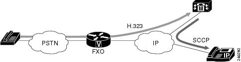
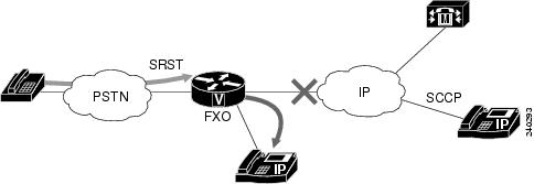
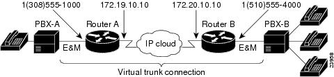
 Feedback