IP Routing: Protocol-Independent Configuration Guide, Cisco IOS Release 15M&T
Bias-Free Language
The documentation set for this product strives to use bias-free language. For the purposes of this documentation set, bias-free is defined as language that does not imply discrimination based on age, disability, gender, racial identity, ethnic identity, sexual orientation, socioeconomic status, and intersectionality. Exceptions may be present in the documentation due to language that is hardcoded in the user interfaces of the product software, language used based on RFP documentation, or language that is used by a referenced third-party product. Learn more about how Cisco is using Inclusive Language.
This module describes how to configure basic IP routing. The Internet Protocol (IP) is a network layer (Layer 3) protocol
that contains addressing information and some control information that enables packets to be routed. IP is documented in RFC
791 and is the primary network layer protocol in the Internet protocol suite.
Finding Feature Information
Your software release may not support all the features documented in this module. For the latest caveats and feature information,
see
Bug Search Tool and the release notes for your platform and software release. To find information about the features documented in this module,
and to see a list of the releases in which each feature is supported, see the feature information table at the end of this
module.
Use Cisco Feature Navigator to find information about platform support and Cisco software image support. To access Cisco Feature
Navigator, go to
www.cisco.com/go/cfn. An account on Cisco.com is not required.
Information About Basic IP Routing
Variable-Length Subnet Masks
Enhanced Interior Gateway Routing Protocol (EIGRP), Intermediate System-to-Intermediate System (IS-IS), Open Shortest Path
First (OSPF), Routing Information Protocol (RIP) Version 2, and static routes support variable-length subnet masks (VLSMs).
With VLSMs, you can use different masks for the same network number on different interfaces, which allows you to conserve
IP addresses and more efficiently use available address space. However, using VLSMs also presents address assignment challenges
for the network administrator and ongoing administrative challenges.
Refer to RFC 1219 for detailed information about VLSMs and how to correctly assign addresses.
Note
Consider your decision to use VLSMs carefully. You can easily make mistakes in address assignments and you will generally
find that the network is more difficult to monitor using VLSMs.
The best way to implement VLSMs is to keep your existing addressing plan in place and gradually migrate some networks to
VLSMs to recover address space.
Static Routes
Static routes are user-defined routes that cause packets moving between a source and a destination to take a specified path.
Static routes can be important if the device cannot build a route to a particular destination. They are also useful for specifying
a gateway of last resort to which all unroutable packets will be sent.
To configure a static route, use the
ip route prefix mask {ip-address |
interface-type interface-number [ip-address]} [distance] [name] [permanent |
track number] [tag tag] global configuration command.
Static routes remains in the device configuration until you remove them (using the
no ip route global configuration command). However, you can override static routes with dynamic routing information through prudent assignment
of administrative distance values. An administrative distance is a rating of the trustworthiness of a routing information
source, such as an individual router or a group of routers. Numerically, an administrative distance is an integer from 0 to
255. In general, the higher the value, the lower the trust rating. An administrative distance of 255 means the routing information
source cannot be trusted at all and should be ignored.
Each dynamic routing protocol has a default administrative distance, as listed in the table below. If you want a static route
to be overridden by information from a dynamic routing protocol, simply ensure that the administrative distance of the static
route is higher than that of the dynamic protocol.
Table 1. Default Administrative Distances for Dynamic Routing Protocols
intermediate System to Intermediate System (IS-IS)
115
Routing Information Protocol (RIP)
120
Exterior Gateway Routing Protocol (EGP)
140
On Demand Routing (ODR)
160
External EIGRP
170
Internal BGP
200
Unknown
255
Static routes that point to an interface are advertised via RIP, EIGRP, and other dynamic routing protocols, regardless of
whether
redistribute static router configuration commands are specified for those routing protocols. These static routes are advertised because static
routes that point to an interface are considered in the routing table to be connected and hence lose their static nature.
However, if you define a static route to an interface that is not one of the networks defined in a
network command, no dynamic routing protocols will advertise the route unless a
redistribute static command is specified for these protocols.
When an interface goes down, all static routes through that interface are removed from the IP routing table. Also, when the
software can no longer find a valid next hop for the address specified as the address of the forwarding device in a static
route, the static route is removed from the IP routing table.
Note
A packet with an E-class source address (240.0.0.0/4) gets dropped on Cisco ASR 1000 Series Aggregation Services Routers,
although RFC 1812 (Requirements for IP Version 4 Routers) defines this behavior only for destination addresses and not specifically
for source addresses.
Default Routes
Default routes, also known as gateways of last resort, are used to route packets that are addressed to networks not explicitly
listed in the routing table. A device might not be able to determine routes to all networks. To provide complete routing capability,
network administrators use some devices as smart devices and give the remaining devices default routes to the smart device.
(Smart devices have routing table information for the entire internetwork.) Default routes can be either passed along dynamically
or configured manually into individual devices.
Most dynamic interior routing protocols include a mechanism for causing a smart device to generate dynamic default information,
which is then passed along to other devices.
You can configure a default route by using the following commands:
ip default-gateway
ip default-network
ip route 0.0.0.0 0.0.0.0
You can use the
ip default-gateway global configuration command to define a default gateway when IP routing is disabled on a device. For instance, if a device
is a host, you can use this command to define a default gateway for the device. You can also use this command to transfer
a Cisco software image to a device when the device is in boot mode. In boot mode, IP routing is not enabled on the device.
Unlike the
ip default-gateway command, the
ip default-network command can be used when IP routing is enabled on a device. When you specify a network by using the
ip default-network command, the device considers routes to that network for installation as the gateway of last resort on the device.
Gateways of last resort configured by using the
ip default-network command are propagated differently depending on which routing protocol is propagating the default route. For Interior Gateway
Routing Protocol (IGRP) and Enhanced Interior Gateway Routing Protocol (EIGRP) to propagate the default route, the network
specified by the
ip default-network command must be known to IGRP or EIGRP. The network must be an IGRP- or EIGRP-derived network in the routing table, or the
static route used to generate the route to the network must be redistributed into IGRP or EIGRP or advertised into these protocols
by using the
network command. The Routing Information Protocol (RIP) advertises a route to network 0.0.0.0 if a gateway of last resort is configured
by using the
ip default-network command. The network specified in the
ip default-network command need not be explicitly advertised under RIP.
Creating a static route to network 0.0.0.0 0.0.0.0 by using the
ip route 0.0.0.0 0.0.0.0 command is another way to set the gateway of last resort on a device. As with the
ip default-network command, using the static route to 0.0.0.0 is not dependent on any routing protocols. However, IP routing must be enabled
on the device. IGRP does not recognize a route to network 0.0.0.0. Therefore, it cannot propagate default routes created by
using the
ip route 0.0.0.0 0.0.0.0 command. Use the
ip default-network command to have IGRP propagate a default route.
EIGRP propagates a route to network 0.0.0.0, but the static route must be redistributed into the routing protocol.
Depending on your release of the Cisco software, the default route created by using the
ip route 0.0.0.0 0.0.0.0 command is automatically advertised by RIP devices. In some releases, RIP does not advertise the default route if the route
is not learned via RIP. You might have to redistribute the route into RIP by using the
redistribute command.
Default routes created using the
ip route 0.0.0.0 0.0.0.0 command are not propagated by Open Shortest Path First (OSPF) and Intermediate System to Intermediate System (IS-IS). Additionally,
these default routes cannot be redistributed into OSPF or IS-IS by using the
redistribute command. Use the
default-information originate command to generate a default route into an OSPF or IS-IS routing domain.
Default Network
Default networks are used to route packets to destinations not established in the routing table. You can use the
ip default-network network-number global configuration command to configure a default network when IP routing is enabled on the device. When you configure
a default network, the device considers routes to that network for installation as the gateway of last resort on the device.
Gateway of Last Resort
When default information is being passed along through a dynamic routing protocol, no further configuration is required.
The system periodically scans its routing table to choose the optimal default network as its default route. In the case of
the Routing Information Protocol (RIP), there is only one choice, network 0.0.0.0. In the case of Enhanced Interior Gateway
Routing Protocol (EIGRP), there might be several networks that can be candidates for the system default. Cisco software uses
both administrative distance and metric information to determine the default route (gateway of last resort). The selected
default route appears in the gateway of last resort display of the
show ip route privileged EXEC command.
If dynamic default information is not being passed to the software, candidates for the default route are specified with the
ip default-network global configuration command. In this usage, the
ip default-network command takes an unconnected network as an argument. If this network appears in the routing table from any source (dynamic
or static), it is flagged as a candidate default route and is a possible choice as the default route.
If the device has no interface on the default network, but does have a route to it, it considers this network as a candidate
default path. The route candidates are examined and the best one is chosen, based on administrative distance and metric. The
gateway to the best default path becomes the gateway of last resort.
Maximum Number of Paths
By default, most IP routing protocols install a maximum of four parallel routes in a routing table. Static routes always
install six routes. The exception is Border Gateway Protocol (BGP), which by default allows only one path (the best path)
to a destination. However, BGP can be configured to use equal and unequal cost multipath load sharing.
The number of parallel routes that you can configure to be installed in the routing table is dependent on the installed version
of Cisco software. To change the maximum number of parallel paths allowed, use the
maximum-paths number-paths command in router configuration mode.
Multi-Interface Load Splitting
Multi-interface load splitting allows you to efficiently control traffic that travels across multiple interfaces to the same
destination. The
traffic-share min router configuration command specifies that if multiple paths are available to the same destination, only paths with the
minimum metric will be installed in the routing table. The number of paths allowed is never more than six. For dynamic routing
protocols, the number of paths is controlled by the
maximum-paths router configuration command. The static route source can install six paths. If more paths are available, the extra paths
are discarded. If some installed paths are removed from the routing table, pending routes are added automatically.
Routing Information Redistribution
In addition to running multiple routing protocols simultaneously, Cisco software can be configured to redistribute information
from one routing protocol to another. For example, you can configure a device to readvertise Enhanced Interior Gateway Routing
Protocol (EIGRP)-derived routes using the Routing Information Protocol (RIP), or to readvertise static routes using the EIGRP
protocol. Redistribution from one routing protocol to another can be configured in all of the IP-based routing protocols.
You also can conditionally control the redistribution of routes between routing domains by configuring route maps between
the two domains. A route map is a route/packet filter that is configured with permit and deny statements, match and set clauses,
and sequence numbers.
Although redistribution is a protocol-independent feature, some of the
match and
set commands are specific to a particular protocol.
One or more
match commands and one or more
set commands are configured in route map configuration mode. If there are no
match commands, then everything matches. If there are no
set commands, then no set action is performed.
To define a route map for redistribution, use the
route-map map-tag [permit |
deny ] [sequence-number] global configuration command.
The metrics of one routing protocol do not necessarily translate into the metrics of another. For example, the RIP metric
is a hop count and the EIGRP metric is a combination of five metric values. In such situations, a dynamic metric is assigned
to the redistributed route. Redistribution in these cases should be applied consistently and carefully with inbound filtering
to avoid routing loops.
Removing options that you have configured for the
redistribute command requires careful use of the
no redistribute command to ensure that you obtain the result that you are expecting.
Supported Metric Translations
This section describes supported automatic metric translations between the routing protocols. The following descriptions
assume that you have not defined a default redistribution metric that replaces metric conversions:
The Routing Information Protocol (RIP) can automatically redistribute static routes. It assigns static routes a metric of
1 (directly connected).
The Border Gateway Protocol (BGP) does not normally send metrics in its routing updates.
The Enhanced Interior Gateway Routing Protocol (EIGRP) can automatically redistribute static routes from other EIGRP-routed
autonomous systems as long as the static route and any associated interfaces are covered by an EIGRP network statement. EIGRP
assigns static routes a metric that identifies them as directly connected. EIGRP does not change the metrics of routes derived
from EIGRP updates from other autonomous systems.
Note
Note that any protocol can redistribute routes from other routing protocols as long as a default metric is configured.
Protocol Differences in Implementing the no redistribute Command
Caution
Removing options that you have configured for the
redistribute command requires careful use of the
no redistribute command to ensure that you obtain the result that you are expecting. In most cases, changing or disabling any keyword will
not affect the state of other keywords.
Different protocols implement the
no redistribute command differently as follows:
In Border Gateway Protocol (BGP), Open Shortest Path First (OSPF), and Routing Information Protocol (RIP) configurations,
the
no redistribute command removes only the specified keywords from the
redistribute commands in the running configuration. They use the
subtractive keyword method when redistributing from other protocols. For example, in the case of BGP, if you configure
no redistribute static route-map interior , only the route map is removed from the redistribution, leaving
redistribute static in place with no filter.
The
no redistribute isis command removes the Intermediate System to Intermediate System (IS-IS) redistribution from the running configuration. IS-IS
removes the entire command, regardless of whether IS-IS is the redistributed or redistributing protocol.
The Enhanced Interior Gateway Routing Protocol (EIGRP) used the subtractive keyword method prior to EIGRP component version
rel5. Starting with EIGRP component version rel5, the
no redistribute command removes the entire
redistribute command when redistributing from any other protocol.
Sources of Routing Information Filtering
Filtering sources of routing information prioritizes routing information from different sources because some pieces of routing
information might be more accurate than others. An administrative distance is a rating of the trustworthiness of a routing
information source, such as an individual device or a group of devices. In a large network, some routing protocols and some
devices can be more reliable than others as sources of routing information. Also, when multiple routing processes are running
in the same device for IP, the same route could be advertised by more than one routing process. By specifying administrative
distance values, you enable the device to intelligently discriminate between sources of routing information. The device always
picks the route whose routing protocol has the lowest administrative distance.
There are no general guidelines for assigning administrative distances because each network has its own requirements. You
must determine a reasonable matrix of administrative distances for the network as a whole.
For example, consider a device using the Enhanced Interior Gateway Routing Protocol (EIGRP) and the Routing Information Protocol
(RIP). Suppose you trust the EIGRP-derived routing information more than the RIP-derived routing information. In this example,
because the default EIGRP administrative distance is lower than the default RIP administrative distance, the device uses the
EIGRP-derived information and ignores the RIP-derived information. However, if you lose the source of the EIGRP-derived information
(because of a power shutdown at the source network, for example), the device uses the RIP-derived information until the EIGRP-derived
information reappears.
Note
You can also use administrative distance to rate the routing information from devices that are running the same routing protocol.
This application is generally discouraged if you are unfamiliar with this particular use of administrative distance because
it can result in inconsistent routing information, including forwarding loops.
Note
The weight of a route can no longer be set with the
distance command. To set the weight for a route, use a route map.
Authentication Key Management and Supported Protocols
Key management is a method of controlling the authentication keys used by routing protocols. Not all protocols support key
management. Authentication keys are available for Director Response Protocol (DRP) Agent, Enhanced Interior Gateway Routing
Protocol (EIGRP), and Routing Information Protocol (RIP) Version 2.
You can manage authentication keys by defining key chains, identifying the keys that belong to the key chain, and specifying
how long each key is valid. Each key has its own key identifier (specified using the
key chain configuration command), which is stored locally. The combination of the key identifier and the interface associated with
the message uniquely identifies the authentication algorithm and the message digest algorithm 5 (MD5) authentication key in
use.
You can configure multiple keys with lifetimes. Only one authentication packet is sent, regardless of how many valid keys
exist. The software examines the key numbers in ascending order and uses the first valid key it encounters. The lifetimes
allow for overlap during key changes.
How to Configure Basic IP Routing
Redistributing Routing Information
You can redistribute routes from one routing domain into another, with or without controlling the redistribution with a route
map. To control which routes are redistributed, configure a route map and reference the route map from the
redistribute command.
The tasks in this section describe how to define the conditions for redistributing routes (a route map), how to redistribute
routes, and how to remove options for redistributing routes, depending on the protocol being used.
Defining Conditions for Redistributing Routes
Route maps can be used to control route redistribution (or to implement policy-based routing). To define conditions for redistributing
routes from one routing protocol into another, configure the
route-map command. Then use at least one
match command in route map configuration mode, as needed. At least one
match command is used in this task because the purpose of the task is to illustrate how to define one or more conditions on which
to base redistribution.
Note
A route map is not required to have
match commands; it can have only
set commands. If there are no
match commands, everything matches the route map.
Note
There are many more
match commands not shown in this table. For additional
match commands, see the
Cisco IOS Master Command List.
Command or Action
Purpose
match as-path path-list-number
Matches a BGP autonomous system path access list.
match community {standard-list-number | expanded-list-number| community-list-namematch community [exact ]}
Matches a BGP community.
match ip address {access-list-number [access-list-number... | access-list-name...] | access-list-name [access-list-number...| access-list-name] | prefix-list prefix-list-name[prefix-list-name...]}
Matches routes that have a destination network address that is permitted to policy route packets or is permitted by a standard
access list, an extended access list, or a prefix list.
match metric metric-value
Matches routes with the specified metric.
match ip next-hop {access-list-number | access-list-name}[access-list-number | access-list-name]
Matches a next-hop device address passed by one of the specified access lists.
match tag tag-value[tag-value]
Matches the specified tag value.
match interface typenumber [typenumber]
Matches routes that use the specified interface as the next hop.
match ip route-source {access-list-number | access-list-name}[access-list-number | access-list-name]
Matches the address specified by the advertised access lists.
To optionally specify the routing actions for the system to perform if the match criteria are met (for routes that are being
redistributed by the route map), use one or more
set commands in route map configuration mode, as needed.
Note
A route map is not required to have
set commands; it can have only
match commands.
Note
There are more
set commands not shown in this table. For additional
set commands, see the
Cisco IOS Master Command List.
Command or Action
Purpose
set community {community-number [additive ] [well-known ]| none }
Sets the community attribute (for BGP).
set dampening halflifereusesuppressmax-suppress-time
Sets route dampening parameters (for BGP).
set local-preference number-value
Assigns a local preference value to a path (for BGP).
set origin {igp | egp as-number | incomplete }
Sets the route origin code.
set as-path {tag | prepend as-path-string}
Modifies the autonomous system path (for BGP).
set next-hop next-hop
Specifies the address of the next hop.
set automatic-tag
Enables automatic computation of the tag table.
set level {level-1 |level-2 |level-1-2 | stub-area | backbone }
Specifies the areas to import routes.
set metric metric-value
Sets the metric value for redistributed routes (for any protocol, except EIGRP).
set metric bandwidthdelayreliabilityloadmtu
Sets the metric value for redistributed routes (for EIGRP only).
set metric-type {internal | external |type-1 | type-2 }
Sets the metric type for redistributed routes.
set metric-type internal
Sets the Multi Exit Discriminator (MED) value on prefixes advertised to the external BGP neighbor to match the Interior Gateway
Protocol (IGP) metric of the next hop.
set tag tag-value
Sets a tag value to be applied to redistributed routes.
Redistributing Routes from
One Routing Domain to Another
Perform this task
to redistribute routes from one routing domain into another and to control
route redistribution. This task shows how to redistribute OSPF routes into a
BGP domain.
SUMMARY STEPS
enable
configure
terminal
router
bgp autonomous-system
redistribute
protocolprocess-id
default-metric
number
end
DETAILED STEPS
Command or Action
Purpose
Step 1
enable
Example:
Device> enable
Enables
privileged EXEC mode.
Enter your
password if prompted.
Step 2
configure
terminal
Example:
Device# configure terminal
Enters global
configuration mode.
Step 3
router
bgp autonomous-system
Example:
Device(config)# router bgp 109
Enables a BGP
routing process and enters router configuration mode.
Step 4
redistribute
protocolprocess-id
Example:
Device(config-router)# redistribute ospf 2 1
Redistributes
routes from the specified routing domain into another routing domain.
Step 5
default-metric
number
Example:
Device(config-router)# default-metric 10
Sets the
default metric value for redistributed routes.
Note
The metric
value specified in the
redistribute
command supersedes the metric value specified using the
default-metric
command.
Step 6
end
Example:
Device(config-router)# end
Exits router
configuration mode and returns to privileged EXEC mode.
Removing Options for Redistribution Routes
Caution
Removing options that you have configured for the
redistribute command requires careful use of the
no redistribute command to ensure that you obtain the result that you are expecting.
Different protocols implement the
no redistribute command differently as follows:
In BGP, OSPF, and RIP configurations, the
no redistribute command removes only the specified keywords from the
redistribute commands in the running configuration. They use the
subtractive keyword method when redistributing from other protocols. For example, in the case of BGP, if you configure
no redistribute static route-map interior , only the route map is removed from the redistribution, leaving
redistribute static in place with no filter.
The
no redistribute isis command removes the IS-IS redistribution from the running configuration. IS-IS removes the entire command, regardless of
whether IS-IS is the redistributed or redistributing protocol.
EIGRP used the subtractive keyword method prior to EIGRP component version rel5. Starting with EIGRP component version rel5,
the
no redistribute command removes the entire
redistribute command when redistributing from any other protocol.
For the
no redistribute connected command, the behavior is subtractive if the
redistribute command is configured under the
router bgp or the
router ospf command. The behavior is complete removal of the command if it is configured under the
router isis or the
router eigrp command.
The following OSPF commands illustrate how various options are removed from the redistribution in router configuration mode.
Command or Action
Purpose
no redistribute connected metric 1000 subnets
Removes the configured metric value of 1000 and the configured subnets and retains the
redistribute connected command in the configuration.
no redistribute connected metric 1000
Removes the configured metric value of 1000 and retains the
redistribute connected subnets command in the configuration.
no redistribute connected subnets
Removes the configured subnets and retains the
redistribute connected metric metric-value command in the configuration.
no redistribute connected
Removes the
redistribute connected command and any of the options that were configured for the command.
Configuring Routing Information Filtering
Note
When routes are redistributed between Open Shortest Path First (OSPF) processes, no OSPF metrics are preserved.
Controlling the Advertising of Routes in Routing Updates
To prevent other devices from learning one or more routes, you can suppress routes from being advertised in routing updates.
To suppress routes from being advertised in routing updates, use the
distribute-list {access-list-number |
access-list-name}
out [interface-name |
routing-process |
as-number] command in router configuration mode.
You cannot specify an interface name in Open Shortest Path First (OSPF). When used for OSPF, this feature applies only to
external routes.
Controlling the Processing of Routing Updates
You might want to avoid processing certain routes that are listed in incoming updates (this does not apply to Open Shortest
Path First [OSPF] or Intermediate System to Intermediate System [IS-IS]). To suppress routes in incoming updates, use the
distribute-list {access-list-number |
access-list-name}
in [interface-typeinterface-number] command in router configuration mode.
Filtering Sources of Routing Information
To filter sources of routing information, use the
distance
ip-addresswildcard-mask [ip-standard-acl |
ip-extended-acl |
access-list-name] command in router configuration mode.
You can
configure multiple keys with lifetimes. Only one authentication packet is sent,
regardless of how many valid keys exist. The software examines the key numbers
in ascending order and uses the first valid key it encounters. The lifetimes
allow for overlap during key changes.
Device> enable
Enables
privileged EXEC mode.
Enter your
password if prompted.
Step 2
configure
terminal
Example:
Device# configure terminal
Enters global
configuration mode.
Step 3
key chain name-of-chain
Example:
Device(config)# key chain chain1
Defines a key
chain and enters key-chain configuration mode.
Step 4
key number
Example:
Device(config-keychain)# key 1
Identifies
number of an authentication key on a key chain. The range of keys is from 0 to
2147483647. The key identification numbers need not be consecutive.
You can remove all contents of a particular table. Clearing a table may become necessary when the contents of the particular
structure have become, or are suspected to be, invalid.
To clear one or more routes from the IP routing table, use the
clear ip route {network [mask] |
* } command in privileged EXEC mode.
Displaying System and Network Statistics
You can use the following
show commands to display system and network statistics. You can display specific statistics such as contents of IP routing tables,
caches, and databases. You can also display information about node reachability and discover the routing path that packets
leaving your device are taking through the network. This information can an be used to determine resource utilization and
solve network problems.
Command or Action
Purpose
show ip cache policy
Displays cache entries in the policy route cache.
show ip local policy
Displays the local policy route map if one exists.
show ip policy
Displays policy route maps.
show ip protocols
Displays the parameters and current state of the active routing protocols.
show ip route [ip-address [mask] [longer-prefixes ] | protocol [process-id] | list {access-list-number | access-list-name} | static download ]
Displays the current state of the routing table.
show ip route summary
Displays the current state of the routing table in summary form.
show ip route supernets-only
Displays supernets.
show key chain [name-of-chain]
Displays authentication key information.
show route-map [map-name]
Displays all route maps configured or only the one specified.
Configuration Examples for Basic IP Routing
Example: Variable-Length Subnet Mask
The following example uses two different subnet masks for the class B network address of 172.16.0.0. A subnet mask of /24
is used for LAN interfaces. The /24 mask allows 265 subnets with 254 host IP addresses on each subnet. The final subnet of
the range of possible subnets using a /24 mask (172.16.255.0) is reserved for use on point-to-point interfaces and assigned
a longer mask of /30. The use of a /30 mask on 172.16.255.0 creates 64 subnets (172.16.255.0 to 172.16.255.252) with 2 host
addresses on each subnet.
Caution: To ensure unambiguous routing, you must not assign 172.16.255.0/24 to a LAN interface in your network.
Device(config)# interface GigabitEthernet 0/0/0
Device(config-if)# ip address 172.16.1.1 255.255.255.0
Device(config-if)# ! 8 bits of host address space reserved for GigabitEthernet interfaces
Device(config-if)# exit
Device(config)# interface Serial 0/0/0
Device(config-if)# ip address 172.16.255.5 255.255.255.252
Device(config-if)# ! 2 bits of address space reserved for point-to-point serial interfaces
Device(config-if)# exit
Device(config)# router rip
Device(config-router)# network 172.16.0.0
Device(config-router)# ! Specifies the network directly connected to the device
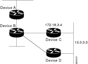
Example: Overriding Static Routes with Dynamic Protocols
In the following example, packets for network 10.0.0.0 from Device B (where the static route is installed) will be routed
through 172.18.3.4 if a route with an administrative distance less than 110 is not available. The figure below illustrates
this example. The route learned by a protocol with an administrative distance of less than 110 might cause Device B to send
traffic destined for network 10.0.0.0 via the alternate path through Device D.
Device(config)# ip route 10.0.0.0 255.0.0.0 172.18.3.4 110
Figure 1. Overriding Static Routes
Example: IP Default Gateway as a Static IP Next Hop When IP Routing Is Disabled
The following example shows how to configure IP address 172.16.5.4 as the default route when IP routing is disabled:
Device> enable
Device# configure terminal
Device(conf)# no ip routing
Device(conf)# ip default-gateway 172.16.15.4
Examples: Administrative Distances
In the following example, the
router eigrp global configuration command configures Enhanced Interior Gateway Routing Protocol (EIGRP) routing in autonomous system 1.
The
network command configuration specifies EIGRP routing on networks 192.168.7.0 and 172.16.0.0. The first
distance router configuration command sets the default administrative distance to 255, which instructs the device to ignore all routing
updates from devices for which an explicit distance has not been set. The second
distance command sets the administrative distance to 80 for internal EIGRP routes and to 100 for external EIGRP routes. The third
distance command sets the administrative distance to 120 for the device with the address 172.16.1.3.
The
distance eigrp command must be used to set the administrative distance for EIGRP-derived routes.
The following example assigns the device with the address 192.168.7.18 an administrative distance of 100 and all other devices
on subnet 192.168.7.0 an administrative distance of 200:
However, if you reverse the order of these two commands, all devices on subnet 192.168.7.0 are assigned an administrative
distance of 200, including the device at address 192.168.7.18:
Assigning administrative distances can be used to solve unique problems. However, administrative distances should be applied
carefully and consistently to avoid the creation of routing loops or other network failures.
In the following example, the distance value for IP routes learned is 90. Preference is given to these IP routes rather than
routes with the default administrative distance value of 110.
Device(config)# router isis
Device(config-router)# distance 90 ip
Example: Static Routing Redistribution
In the example that follows, three static routes are specified, two of which are to be advertised. The static routes are
created by specifying the
redistribute static router configuration command and then specifying an access list that allows only those two networks to be passed to the Enhanced
Interior Gateway Routing Protocol (EIGRP) process. Any redistributed static routes should be sourced by a single device to
minimize the likelihood of creating a routing loop.
Each Enhanced Interior Gateway Routing Protocol (EIGRP) routing process provides routing information to only one autonomous
system. The Cisco software must run a separate EIGRP process and maintain a separate routing database for each autonomous
system that it services. However, you can transfer routing information between these routing databases.
In the following configuration, network 10.0.0.0 is configured under EIGRP autonomous system 1 and network 192.168.7.0 is
configured under EIGRP autonomous system 101:
In the following example, routes from the 192.168.7.0 network are redistributed into autonomous system 1 (without passing
any other routing information from autonomous system 101):
The following example is an alternative way to redistribute routes from the 192.168.7.0 network into autonomous system 1.
Unlike the previous configuration, this method does not allow you to set the metric for redistributed routes.
Example: Mutual Redistribution Between EIGRP and RIP
Consider a WAN at a university that uses the Routing Information Protocol (RIP) as an interior routing protocol. Assume that
the university wants to connect its WAN to regional network 172.16.0.0, which uses the Enhanced Interior Gateway Routing Protocol
(EIGRP) as the routing protocol. The goal in this case is to advertise the networks in the university network to devices in
the regional network.
Mutual redistribution is configured between EIGRP and RIP in the following example:
In this example, an EIGRP routing process is started. The
network router configuration command specifies that network 172.16.0.0 (the regional network) is to send and receive EIGRP routing
information. The
redistribute router configuration command specifies that RIP-derived routing information be advertised in routing updates. The
default-metric router configuration command assigns an EIGRP metric to all RIP-derived routes. The
distribute-list router configuration command instructs the Cisco software to use access list 10 (not defined in this example) to limit the
entries in each outgoing update. The access list prevents unauthorized advertising of university routes to the regional network.
Example: Mutual Redistribution Between EIGRP and BGP
In the following example, mutual redistribution is configured between the Enhanced Interior Gateway Routing Protocol (EIGRP)
and the Border Gateway Protocol (BGP).
Routes from EIGRP routing process 101 are injected into BGP autonomous system 50000. A filter is configured to ensure that
the correct routes are advertised, in this case, three networks. Routes from BGP autonomous system 50000 are injected into
EIGRP routing process 101. The same filter is used.
Device(config)# ! All networks that should be advertised from R1 are controlled with ACLs:
Device(config)# access-list 1 permit 172.18.0.0 0.0.255.255
Device(config)# access-list 1 permit 172.16.0.0 0.0.255.255
Device(config)# access-list 1 permit 172.25.0.0 0.0.255.255
Device(config)# ! Configuration for router R1:
Device(config)# router bgp 50000
Device(config-router)# network 172.18.0.0
Device(config-router)# network 172.16.0.0
Device(config-router)# neighbor 192.168.10.1 remote-as 2
Device(config-router)# neighbor 192.168.10.15 remote-as 1
Device(config-router)# neighbor 192.168.10.24 remote-as 3
Device(config-router)# redistribute eigrp 101
Device(config-router)# distribute-list 1 out eigrp 101
Device(config-router)# exit
Device(config)# router eigrp 101
Device(config-router)# network 172.25.0.0
Device(config-router)# redistribute bgp 50000
Device(config-router)# distribute-list 1 out bgp 50000
Device(config-router)# !
Caution
BGP should be redistributed into an Interior Gateway Protocol (IGP) when there are no other suitable options. Redistribution
from BGP into any IGP should be applied with proper filtering by using distribute lists, IP prefix lists, and route map statements
to limit the number of prefixes.
Examples: OSPF Routing and Route Redistribution
OSPF typically requires coordination among many internal devices, area border routers (ABRs), and Autonomous System Boundary
Routers (ASBRs). At a minimum, OSPF-based devices can be configured with all default parameter values, with no authentication,
and with interfaces assigned to areas.
This section provides the following configuration examples:
The first example shows simple configurations illustrating basic OSPF commands.
The second example shows configurations for an internal device, ABR, and ASBR within a single, arbitrarily assigned OSPF
autonomous system.
The third example illustrates a more complex configuration and the application of various tools available for controlling
OSPF-based routing environments.
Examples: Basic OSPF Configuration
The following example illustrates a simple OSPF configuration that enables OSPF routing process 1, attaches Gigabit Ethernet
interface 0/0/0 to area 0.0.0.0, and redistributes RIP into OSPF and OSPF into RIP:
The following example illustrates the assignment of four area IDs to four IP address ranges. In the example, OSPF routing
process 1 is initialized, and four OSPF areas are defined: 10.9.50.0, 2, 3, and 0. Areas 10.9.50.0, 2, and 3 mask specific
address ranges, whereas area 0 enables OSPF for all other networks.
Device(config)# router ospf 1
Device(config-router)# network 172.18.20.0 0.0.0.255 area 10.9.50.0
Device(config-router)# network 172.18.0.0 0.0.255.255 area 2
Device(config-router)# network 172.19.10.0 0.0.0.255 area 3
Device(config-router)# network 0.0.0.0 255.255.255.255 area 0
Device(config-router)# exit
Device(config)# ! GigabitEthernet interface 0/0/0 is in area 10.9.50.0:
Device(config)# interface GigabitEthernet 0/0/0
Device(config-if)# ip address 172.18.20.5 255.255.255.0
Device(config-if)# exit
Device(config)# ! GigabitEthernet interface 1/0/0 is in area 2:
Device(config)# interface GigabitEthernet 1/0/0
Device(config-if)# ip address 172.18.1.5 255.255.255.0
Device(config-if)# exit
Device(config)# ! GigabitEthernet interface 2/0/0 is in area 2:
Device(config)# interface GigabitEthernet 2/0/0
Device(config-if)# ip address 172.18.2.5 255.255.255.0
Device(config-if)# exit
Device(config)# ! GigabitEthernet interface 3/0/0 is in area 3:
Device(config)# interface GigabitEthernet 3/0/0
Device(config-if)# ip address 172.19.10.5 255.255.255.0
Device(config-if)# exit
Device(config)# ! GigabitEthernet interface 4/0/0 is in area 0:
Device(config)# interface GigabitEthernet 4/0/0
Device(config-if)# ip address 172.19.1.1 255.255.255.0
Device(config-if)# exit
Device(config)# ! GigabitEthernet interface 5/0/0 is in area 0:
Device(config)# interface GigabitEthernet 5/0/0
Device(config-if)# ip address 10.1.0.1 255.255.0.0
Device(config-if)# !
Each
network router configuration command is evaluated sequentially, so the specific order of these commands in the configuration is important.
The Cisco software sequentially evaluates the
address/wildcard-mask pair for each interface. See the
IP Routing Protocols Command Reference for more information.
Consider the first
network command. Area ID 10.9.50.0 is configured for the interface on which subnet 172.18.20.0 is located. Assume that a match is
determined for Gigabit Ethernet interface 0/0/0. Gigabit Ethernet interface 0/0/0 is attached to Area 10.9.50.0 only.
The second
network command is evaluated next. For Area 2, the same process is then applied to all interfaces (except Gigabit Ethernet interface
0/0/0). Assume that a match is determined for Gigabit Ethernet interface 1/0/0. OSPF is then enabled for that interface, and
Gigabit Ethernet 1/0/0 is attached to Area 2.
This process of attaching interfaces to OSPF areas continues for all
network commands. Note that the last
network command in this example is a special case. With this command, all available interfaces (not explicitly attached to another
area) are attached to Area 0.
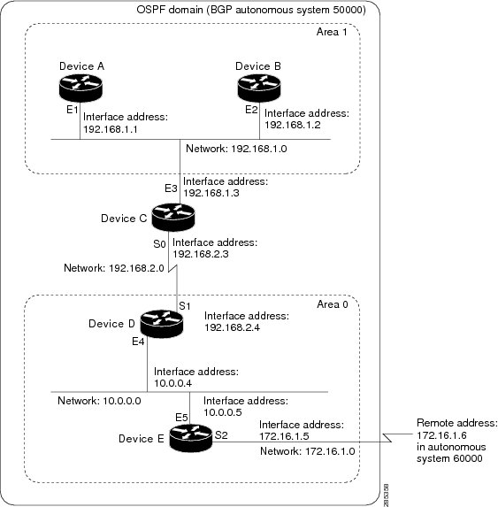
Example: Internal Device ABR and ASBRs Configuration
The figure below provides a general network map that illustrates a sample configuration for several devices within a single
OSPF autonomous system.
Figure 2. Example OSPF Autonomous System Network Map
In this configuration, five devices are configured in OSPF autonomous system 1:
Device A and Device B are both internal devices within area 1.
Device C is an OSPF ABR. Note that for Device C, area 1 is assigned to E3 and Area 0 is assigned to S0.
Device D is an internal device in area 0 (backbone area). In this case, both
network router configuration commands specify the same area (area 0, or the backbone area).
Device E is an OSPF ASBR. Note that the Border Gateway Protocol (BGP) routes are redistributed into OSPF and that these routes
are advertised by OSPF.
Note
Definitions of all areas in an OSPF autonomous system need not be included in the configuration of all devices in the autonomous
system. You must define only the
directly connected areas. In the example that follows, routes in Area 0 are learned by the devices in area 1 (Device A and Device
B) when the ABR (Device C) injects summary link state advertisements (LSAs) into area 1.
Autonomous system 60000 is connected to the outside world via the BGP link to the external peer at IP address 172.16.1.6.
Following is the sample configuration for the general network map shown in the figure above.
The following sample configuration accomplishes several tasks in setting up an ABR. These tasks can be split into two general
categories:
Basic OSPF configuration
Route redistribution
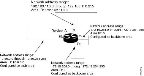
The specific tasks outlined in this configuration are detailed briefly in the following descriptions. The figure below illustrates
the network address ranges and area assignments for the interfaces.
Figure 3. Interface and Area Specifications for OSPF Configuration Example
The basic configuration tasks in this example are as follows:
Configure address ranges for Gigabit Ethernet interface 0/0/0 through Gigabit Ethernet interface 3/0/0.
Enable OSPF on each interface.
Set up an OSPF authentication password for each area and network.
Assign link-state metrics and other OSPF interface configuration options.
Create a stub area with area ID 10.0.0.0. (Note that the
authentication and
stub options of the
area router configuration command are specified with separate
area command entries, but they can be merged into a single
area command.)
Specify the backbone area (area 0).
Configuration tasks associated with redistribution are as follows:
Redistribute the Enhanced Interior Gateway Routing Protocol (EIGRP) and the Routing Information Protocol (RIP) into OSPF
with various options set (including metric-type, metric, tag, and subnet).
Redistribute EIGRP and OSPF into RIP.
The following is an example OSPF configuration:
Device(config)# interface GigabitEthernet 0/0/0
Device(config-if)# ip address 192.168.110.201 255.255.255.0
Device(config-if)# ip ospf authentication-key abcdefgh
Device(config-if)# ip ospf cost 10
Device(config-if)# exit
Device(config)# interface GigabitEthernet 1/0/0
Device(config-if)# ip address 172.19.251.201 255.255.255.0
Device(config-if)# ip ospf authentication-key ijklmnop
Device(config-if)# ip ospf cost 20
Device(config-if)# ip ospf retransmit-interval 10
Device(config-if)# ip ospf transmit-delay 2
Device(config-if)# ip ospf priority 4
Device(config-if)# exit
Device(config)# interface GigabitEthernet 2/0/0
Device(config-if)# ip address 172.19.254.201 255.255.255.0
Device(config-if)# ip ospf authentication-key abcdefgh
Device(config-if)# ip ospf cost 10
Device(config-if)# exit
Device(config)# interface GigabitEthernet 3/0/0
Device(config-if)# ip address 10.56.0.201 255.255.0.0
Device(config-if)# ip ospf authentication-key ijklmnop
Device(config-if)# ip ospf cost 20
Device(config-if)# ip ospf dead-interval 80
Device(config-if)# exit
In the following configuration, OSPF is on network 172.19.0.0:
Device(config)# router ospf 1
Device(config-router)# network 10.0.0.0 0.255.255.255 area 10.0.0.0
Device(config-router)# network 192.168.110.0 0.0.0.255 area 192.168.110.0
Device(config-router)# network 172.19.0.0 0.0.255.255 area 0
Device(config-router)# area 0 authentication
Device(config-router)# area 10.0.0.0 stub
Device(config-router)# area 10.0.0.0 authentication
Device(config-router)# area 10.0.0.0 default-cost 20
Device(config-router)# area 192.168.110.0 authentication
Device(config-router)# area 10.0.0.0 range 10.0.0.0 255.0.0.0
Device(config-router)# area 192.168.110.0 range 192.168.110.0 255.255.255.0
Device(config-router)# area 0 range 172.19.251.0 255.255.255.0
Device(config-router)# area 0 range 172.19.254.0 255.255.255.0
Device(config-router)# redistribute eigrp 200 metric-type 2 metric 1 tag 200 subnets
Device(config-router)# redistribute rip metric-type 2 metric 1 tag 200
Device(config-router)# exit
In the following configuration, EIGRP autonomous system 1 is on 172.19.0.0:
The following example shows a device in autonomous system 1 that is configured to run both the Routing Information Protocol
(RIP) and the Enhanced Interior Gateway Routing Protocol (EIGRP). The example advertises EIGRP-derived routes using RIP and
assigns the EIGRP-derived routes a RIP metric of 10.
Examples: Redistribution With and Without Route Maps
The examples in this section illustrate the use of redistribution, with and without route maps. Examples from both the IP
and Connectionless Network Service (CLNS) routing protocols are given. The following example redistributes all Open Shortest
Path First (OSPF) routes into the Enhanced Interior Gateway Routing Protocol (EIGRP):
The following example redistributes Routing Information Protocol (RIP) routes with a hop count equal to 1 into OSPF. These
routes will be redistributed into OSPF as external link state advertisements (LSAs) with a metric of 5, metric a type of type
1, and a tag equal to 1.
Device(config)# router ospf 1
Device(config-router)# redistribute rip route-map rip-to-ospf
Device(config-router)# exit
Device(config)# route-map rip-to-ospf permit
Device(config-route-map)# match metric 1
Device(config-route-map)# set metric 5
Device(config-route-map)# set metric-type type 1
Device(config-route-map)# set tag 1
Device(config-route-map)# exit
The following example redistributes OSPF learned routes with tag 7 as a RIP metric of 15:
Device(config)# router rip
Device(config-router)# redistribute ospf 1 route-map 5
Device(config-router)# exit
Device(config)# route-map 5 permit
Device(config-route-map)# match tag 7
Device(config-route-map)# set metric 15
The following example redistributes OSPF intra-area and interarea routes with next hop devices on serial interface 0/0/0
into the Border Gateway Protocol (BGP) with an INTER_AS metric of 5:
Device(config)# router bgp 50000
Device(config-router)# redistribute ospf 1 route-map 10
Device(config-router)# exit
Device(config)# route-map 10 permit
Device(config-route-map)# match route-type internal
Device(config-route-map)# match interface serial 0/0/0
Device(config-route-map)# set metric 5
The following example redistributes two types of routes into the integrated IS-IS routing table (supporting both IP and CLNS).
The first type is OSPF external IP routes with tag 5; these routes are inserted into Level 2 IS-IS link-state packets (LSPs)
with a metric of 5. The second type is ISO-IGRP derived CLNS prefix routes that match CLNS access list 2000; these routes
will be redistributed into IS-IS as Level 2 LSPs with a metric of 30.
Device(config)# router isis
Device(config-router)# redistribute ospf 1 route-map 2
Device(config-router)# redistribute iso-igrp nsfnet route-map 3

Device(config-router)# exit
Device(config)# route-map 2 permit
Device(config-route-map)# match route-type external
Device(config-route-map)# match tag 5
Device(config-route-map)# set metric 5
Device(config-route-map)# set level level-2
Device(config-route-map)# exit
Device(config)# route-map 3 permit
Device(config-route-map)# match address 2000
Device(config-route-map)# set metric 30
Device(config-route-map)# exit
With the following configuration, OSPF external routes with tags 1, 2, 3, and 5 are redistributed into RIP with metrics of
1, 1, 5, and 5, respectively. The OSPF routes with a tag of 4 are not redistributed.
Device(config)# router rip
Device(config-router)# redistribute ospf 101 route-map 1
Device(config-router)# exit
Device(config)# route-map 1 permit
Device(config-route-map)# match tag 1 2
Device(config-route-map)# set metric 1
Device(config-route-map)# exit
Device(config)# route-map 1 permit
Device(config-route-map)# match tag 3
Device(config-route-map)# set metric 5
Device(config-route-map)# exit
Device(config)# route-map 1 deny
Device(config-route-map)# match tag 4
Device(config-route-map)# exit
Device(config)# route map 1 permit
Device(config-route-map)# match tag 5
Device(config-route-map)# set metric 5
Device(config-route-map)# exit
Given the following configuration, a RIP learned route for network 172.18.0.0 and an ISO-IGRP learned route with prefix 49.0001.0002
will be redistributed into an IS-IS Level 2 LSP with a metric of 5:
The following configuration example illustrates how a route map is referenced by the
default-information router configuration command. This type of reference is called conditional default origination. OSPF will originate the default
route (network 0.0.0.0) with a type 2 metric of 5 if 172.20.0.0 is in the routing table.
Device(config)# route-map ospf-default permit
Device(config-route-map)# match ip address 1
Device(config-route-map)# set metric 5
Device(config-route-map)# set metric-type type-2
Device(config-route-map)# exit
Device(config)# access-list 1 172.20.0.0 0.0.255.255
Device(config)# router ospf 101
Device(config-router)# default-information originate route-map ospf-default
Examples: Key Management
The following example configures a key chain named chain1. In this example, the software always accepts and sends key1 as
a valid key. The key key2 is accepted from 1:30 p.m. to 3:30 p.m. and is sent from 2:00 p.m. to 3:00 p.m. The overlap allows
for migration of keys or discrepancy in the set time of the device. Likewise, the key key3 immediately follows key2, and there
is 30-minutes on each side to handle time-of-day differences.
The Cisco
Support and Documentation website provides online resources to download
documentation, software, and tools. Use these resources to install and
configure the software and to troubleshoot and resolve technical issues with
Cisco products and technologies. Access to most tools on the Cisco Support and
Documentation website requires a Cisco.com user ID and password.
The following table provides release information about the feature or features described in this module. This table lists
only the software release that introduced support for a given feature in a given software release train. Unless noted otherwise,
subsequent releases of that software release train also support that feature.
Use Cisco Feature Navigator to find information about platform support and Cisco software image support. To access Cisco
Feature Navigator, go to www.cisco.com/go/cfn. An account on Cisco.com is not required.
Table 2. Feature Information for Basic
IP Routing
Feature
Name
Releases
Feature
Information
IP Routing
The IP
Routing feature introduced basic IP routing features that are documented
throughout this module and also in other IP Routing Protocol modules.


 Feedback