- Configuring OSPF
- IPv6 Routing: OSPFv3
- IPv6 Routing: OSPFv3 Authentication Support with IPsec
- OSPFv2 Cryptographic Authentication
- OSPFv3 IPSec ESP Encryption and Authentication
- OSPF ABR Type 3 LSA Filtering
- OSPF Stub Router Advertisement
- OSPF Update Packet-Pacing Configurable Timers
- OSPF Sham-Link Support for MPLS VPN
- OSPF Retransmissions Limit
- OSPF Support for Multi-VRF on CE Routers
- OSPFv2 Multiarea Adjacency
- OSPFv2 Autoroute Exclude
- OSPFv3 Multiarea Adjacency
- OSPFv3 Authentication Trailer
- OSPFv3 Autoroute Exclude
- OSPFv2-OSPF Live-Live
- OSPFv3 Address Families
- OSPF Forwarding Address Suppression in Translated Type-5 LSAs
- OSPF Inbound Filtering Using Route Maps with a Distribute List
- OSPFv3 Fast Convergence: LSA and SPF Throttling
- OSPF Shortest Path First Throttling
- OSPF Support for Fast Hello Packets
- OSPF Incremental SPF
- OSPF Limit on Number of Redistributed Routes
- OSPFv3 Max-Metric Router LSA
- OSPF Link-State Advertisement Throttling
- OSPF Support for Unlimited Software VRFs per PE Router
- OSPF Area Transit Capability
- OSPF Per-Interface Link-Local Signaling
- OSPF Link-State Database Overload Protection
- OSPF Enhanced Traffic Statistics for OSPFv2 and OSPFv3
- OSPF MIB Support of RFC 1850 and Latest Extensions
- SNMP ifIndex Value for Interface ID in OSPFv2 and OSPFv3 Data Fields
- OSPFv3 Graceful Restart
- OSPF RFC 3623 Graceful Restart Helper Mode
- OSPF Mechanism to Exclude Connected IP Prefixes from LSA Advertisements
- OSPFv2 Local RIB
- OSPFv3 MIB
- TTL Security Support for OSPFv3 on IPv6
- OSPFv3 VRF-Lite/PE-CE
- Graceful Shutdown Support for OSPFv3
- Prefix Suppression Support for OSPFv3
- OSPFv3 ABR Type 3 LSA Filtering
OSPF Sham-Link Support for MPLS VPN
Feature History
|
Release |
Modification |
|---|---|
|
12.2(8)T |
This feature was introduced. |
This module describes how to configure and use a sham-link to connect Virtual Private Network (VPN) client sites that run the Open Shortest Path First (OSPF) protocol and share backdoor OSPF links in a Multiprotocol Label Switching (MPLS) VPN configuration.
- Finding Feature Information
- Feature Overview
- Supported Platforms
- Supported Standards MIBs and RFCs
- Prerequisites
- Configuration Tasks
- Monitoring and Maintaining a Sham-Link
- Configuration Examples
- Glossary
Finding Feature Information
Your software release may not support all the features documented in this module. For the latest caveats and feature information, see Bug Search Tool and the release notes for your platform and software release. To find information about the features documented in this module, and to see a list of the releases in which each feature is supported, see the feature information table.
Use Cisco Feature Navigator to find information about platform support and Cisco software image support. To access Cisco Feature Navigator, go to www.cisco.com/go/cfn. An account on Cisco.com is not required.
Feature Overview
- Using OSPF in PE-CE Router Connections
- Using a Sham-Link to Correct OSPF Backdoor Routing
- Sham-Link Configuration Example
- Benefits
- Restrictions
- Related Features and Technologies
- Related Documents
Using OSPF in PE-CE Router Connections
In an MPLS VPN configuration, the OSPF protocol is one way you can connect customer edge (CE) routers to service provider edge (PE) routers in the VPN backbone. OSPF is often used by customers that run OSPF as their intrasite routing protocol, subscribe to a VPN service, and want to exchange routing information between their sites using OSPF (during migration or on a permanent basis) over an MPLS VPN backbone.
The figure below shows an example of how VPN client sites that run OSPF can connect over an MPLS VPN backbone.
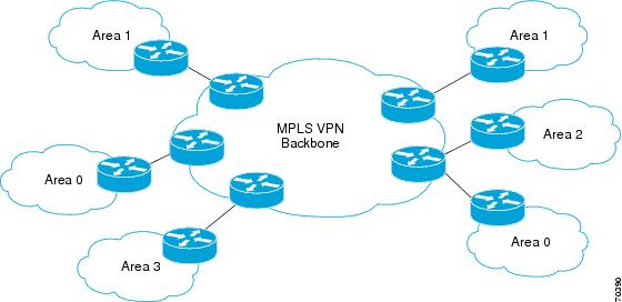
When OSPF is used to connect PE and CE routers, all routing information learned from a VPN site is placed in the VPN routing and forwarding (VRF) instance associated with the incoming interface. The PE routers that attach to the VPN use the Border Gateway Protocol (BGP) to distribute VPN routes to each other. A CE router can then learn the routes to other sites in the VPN by peering with its attached PE router. The MPLS VPN superbackbone provides an additional level of routing hierarchy to interconnect the VPN sites running OSPF.
When OSPF routes are propagated over the MPLS VPN backbone, additional information about the prefix in the form of BGP extended communities (route type, domain ID extended communities) is appended to the BGP update. This community information is used by the receiving PE router to decide the type of link-state advertisement (LSA) to be generated when the BGP route is redistributed to the OSPF PE-CE process. In this way, internal OSPF routes that belong to the same VPN and are advertised over the VPN backbone are seen as interarea routes on the remote sites.
For basic information about how to configure an MPLS VPN, refer to the "MPLS Virtual Private Networks Configuration" module.
Using a Sham-Link to Correct OSPF Backdoor Routing
Although OSPF PE-CE connections assume that the only path between two client sites is across the MPLS VPN backbone, backdoor paths between VPN sites (shown in grey in the figure below) may exist. If these sites belong to the same OSPF area, the path over a backdoor link will always be selected because OSPF prefers intraarea paths to interarea paths. (PE routers advertise OSPF routes learned over the VPN backbone as interarea paths.) For this reason, OSPF backdoor links between VPN sites must be taken into account so that routing is performed based on policy.
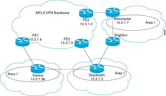
For example, the figure above shows three client sites, each with backdoor links. Because each site runs OSPF within the same Area 1 configuration, all routing between the three sites follows the intraarea path across the backdoor links, rather than over the MPLS VPN backbone.
The following example shows BGP routing table entries for the prefix 10.3.1.7/32 in the PE-1 router in the figure above. This prefix is the loopback interface of the Winchester CE router. As shown in bold in this example, the loopback interface is learned via BGP from PE-2 and PE-3. It is also generated through redistribution into BGP on PE-1.
PE-1# show ip bgp vpnv4 all 10.3.1.7
BGP routing table entry for 100:251:10.3.1.7/32, version 58
Paths: (3 available, best #2)
  Advertised to non peer-group peers:
  10.3.1.2 10.3.1.5
  Local
    10.3.1.5 (metric 30) from 10.3.1.5 (10.3.1.5)
      Origin incomplete, metric 22, localpref 100, valid, internal
      Extended Community: RT:1:793 OSPF DOMAIN ID:0.0.0.100 OSPF
      RT:1:2:0 OSPF 2
  Local
    10.2.1.38 from 0.0.0.0 (10.3.1.6)
      Origin incomplete, metric 86, localpref 100, weight 32768,
      valid, sourced, best
      Extended Community: RT:1:793 OSPF DOMAIN ID:0.0.0.100 OSPF
      RT:1:2:0 OSPF 2
  Local
    10.3.1.2 (metric 30) from 10.3.1.2 (10.3.1.2)
      Origin incomplete, metric 11, localpref 100, valid, internal
      Extended Community: RT:1:793 OSPF DOMAIN ID:0.0.0.100 OSPF
      RT:1:2:0 OSPF 2
Within BGP, the locally generated route (10.2.1.38) is considered to be the best route. However, as shown in bold in the next example, the VRF routing table shows that the selected path is learned via OSPF with a next hop of 10.2.1.38, which is the Vienna CE router.
PE-1# show ip route vrf ospf 10.3.1.7
Routing entry for 10.3.1.7/32
  Known via "ospf 100", distance 110, metric 86, type intra area
  Redistributing via bgp 215
  Advertised by bgp 215
  Last update from 10.2.1.38 on Serial0/0/0, 00:00:17 ago
  Routing Descriptor Blocks:
  * 10.2.1.38
, from 10.3.1.7, 00:00:17 ago, via Serial0/0/0
      Route metric is 86, traffic share count is 1
This path is selected because:
The OSPF intra-area path is preferred over the interarea path (over the MPLS VPN backbone) generated by the PE-1 router.
OSPF has a lower administrative distance (AD) than internal BGP (BGP running between routers in the same autonomous system).
If the backdoor links between sites are used only for backup purposes and do not participate in the VPN service, then the default route selection shown in the preceding example is not acceptable. To reestablish the desired path selection over the MPLS VPN backbone, you must create an additional OSPF intra-area (logical) link between ingress and egress VRFs on the relevant PE routers. This link is called a sham-link.
A sham-link is required between any two VPN sites that belong to the same OSPF area and share an OSPF backdoor link. If no backdoor link exists between the sites, no sham-link is required.
The figure below shows a sample sham-link between PE-1 and PE-2. A cost is configured with each sham-link and is used to decide whether traffic will be sent over the backdoor path or the sham-link path. When a sham-link is configured between PE routers, the PEs can populate the VRF routing table with the OSPF routes learned over the sham-link.
Because the sham-link is seen as an intra-area link between PE routers, an OSPF adjacency is created and database exchange (for the particular OSPF process) occurs across the link. The PE router can then flood LSAs between sites from across the MPLS VPN backbone. As a result, the desired intra-area connectivity is created.
The section, "Creating a Sham-Link", describes how to configure a sham-link between two PE routers. For more information about how to configure OSPF, refer to the "Configuring OSPF" module.
Sham-Link Configuration Example
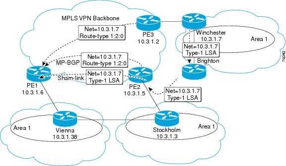
The example in this section is designed to show how a sham-link is used only to affect the OSPF intra-area path selection of the PE and CE routers. The PE router also uses the information received from MP-BGP to set the outgoing label stack of incoming packets, and to decide to which egress PE router to label switch the packets.
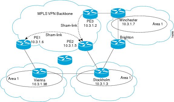
The figure below shows a sample MPLS VPN topology in which a sham-link configuration is necessary. A VPN client has three sites, each with a backdoor link. Two sham-links have been configured, one between PE-1 and PE-2, and another between PE-2 and PE-3. A sham-link between PE-1 and PE-3 is not necessary in this configuration because the Vienna and Winchester sites do not share a backdoor link.
The following example shows the forwarding that occurs between sites from the standpoint of how PE-1 views the 10.3.1.7/32 prefix, the loopback1 interface of the Winchester CE router in the figure above.
PE-1# show ip bgp vpnv4 all 10.3.1.7
BGP routing table entry for 100:251:10.3.1.7/32, version 124
Paths: (1 available, best #1)
  Local
    10.3.1.2 (metric 30) from 10.3.1.2
 (10.3.1.2)
       Origin incomplete, metric 11, localpref 100, valid, internal,
       best
       Extended Community: RT:1:793 OSPF DOMAIN ID:0.0.0.100 OSPF
       RT:1:2:0 OSPF 2
PE-1# show ip route vrf ospf 10.3.1.7
Routing entry for 10.3.1.7/32
  Known via "ospf 100
", distance 110, metric 13, type intra area
  Redistributing via bgp 215
  Last update from 10.3.1.2 00:12:59 ago
  Routing Descriptor Blocks:
10.3.1.2 (Default-IP-Routing-Table), from 10.3.1.7, 00:12:59 ago
The next example shows forwarding information in which the next hop for the route, 10.3.1.2, is the PE-3 router rather than the PE-2 router (which is the best path according to OSPF). The reason the OSPF route is not redistributed to BGP on the PE is because the other end of the sham-link already redistributed the route to BGP and there is no need for duplication. The OSPF sham-link is used only to influence intra-area path selection. When sending traffic to a particular destination, the PE router uses the MP-BGP forwarding information.
PE-1# show ip bgp vpnv4 all tag | begin 10.3.1.7
   10.3.1.7/32      10.3.1.2
        notag/38

PE-1# show tag-switching forwarding 10.3.1.2
Local  Outgoing   Prefix           Bytes tag  Outgoing   Next Hop
tag    tag or VC  or Tunnel Id     switched   interface
31    42         10.3.1.2/32
       0          PO3/0/0    point2point
PE-1# show ip cef vrf ospf 10.3.1.7
10.3.1.7/32, version 73, epoch 0, cached adjacency to POS3/0/0
0 packets, 0 bytes
  tag information set
   local tag: VPN-route-head
   fast tag rewrite with PO3/0/0, point2point, tags imposed: {42 38
}
  via 10.3.1.2
, 0 dependencies, recursive
    next hop 10.1.1.17, POS3/0/0 via 10.3.1.2/32
    valid cached adjacency
    tag rewrite with PO3/0/0, point2point, tags imposed: {42 38}
If a prefix is learned across the sham-link and the path via the sham-link is selected as the best, the PE router does not generate an MP-BGP update for the prefix. It is not possible to route traffic from one sham-link over another sham-link.
In the following example, PE-2 shows how an MP-BGP update for the prefix is not generated. Although 10.3.1.7/32 has been learned via OSPF across the sham-link as shown in bold, no local generation of a route into BGP is performed. The only entry within the BGP table is the MP-BGP update received from PE-3 (the egress PE router for the 10.3.1.7/32 prefix).
PE-2# show ip route vrf ospf 10.3.1.7
Routing entry for 10.3.1.7/32
  Known via "ospf 100
", distance 110, metric 12, type intra area
  Redistributing via bgp 215
  Last update from 10.3.1.2 00:00:10 ago
  Routing Descriptor Blocks:
  * 10.3.1.2 (Default-IP-Routing-Table), from 10.3.1.7, 00:00:10 ago
      Route metric is 12, traffic share count is 1
PE-2# show ip bgp vpnv4 all 10.3.1.7
BGP routing table entry for 100:251:10.3.1.7/32, version 166
Paths: (1 available, best #1)
  Not advertised to any peer
  Local
    10.3.1.2 (metric 30) from 10.3.1.2 (10.3.1.2)
      Origin incomplete, metric 11, localpref 100, valid, internal,
      best
      Extended Community: RT:1:793 OSPF DOMAIN ID:0.0.0.100 OSPF
      RT:1:2:0 OSPF 2
The PE router uses the information received from MP-BGP to set the ongoing label stack of incoming packets, and to decide to which egress PE router to label switch the packets.
Benefits
Client Site Connection Across the MPLS VPN Backbone
A sham-link overcomes the OSPF default behavior for selecting an intra-area backdoor route between VPN sites instead of an interarea (PE-to-PE) route. A sham-link ensures that OSPF client sites that share a backdoor link can communicate over the MPLS VPN backbone and participate in VPN services.
Flexible Routing in an MPLS VPN Configuration
In an MPLS VPN configuration, the OSPF cost configured with a sham-link allows you to decide if OSPF client site traffic will be routed over a backdoor link or through the VPN backbone.
Restrictions
When OSPF is used as a protocol between PE and CE routers, the OSPF metric is preserved when routes are advertised over the VPN backbone. The metric is used on the remote PE routers to select the correct route. For this reason, you should not modify the metric value when OSPF is redistributed to BGP, and when BGP is redistributed to OSPF. If you modify the metric value, routing loops may occur.
Related Features and Technologies
MPLS
OSPF
BGP
Related Documents
Supported Platforms
Cisco 1400 series
Cisco 1600
Cisco 1600R
Cisco 1710
Cisco 1720
Cisco 1721
Cisco 1750
Cisco 1751
Cisco 2420
Cisco 2600
Cisco 2691
Cisco 3620
Cisco 3631
Cisco 3640
Cisco 3660
Cisco 3725
Cisco 3745
Cisco 7100
Cisco 7200
Cisco 7500
Cisco 7700
URM
Cisco uBR7200
Determining Platform Support Through Cisco Feature Navigator
Cisco IOS software is packaged in feature sets that support specific platforms. To get updated information regarding platform support for this feature, access Cisco Feature Navigator. Cisco Feature Navigator dynamically updates the list of supported platforms as new platform support is added for the feature.
Cisco Feature Navigator is a web-based tool that enables you to quickly determine which Cisco IOS software images support a specific set of features and which features are supported in a specific Cisco IOS image. You can search by feature or release. Under the release section, you can compare releases side by side to display both the features unique to each software release and the features in common.
Cisco Feature Navigator is updated regularly when major Cisco IOS software releases and technology releases occur. For the most current information, go to the Cisco Feature Navigator home page at the following URL:
Supported Standards MIBs and RFCs
Standards
No new or modified standards are supported by this feature.
MIBs
No new or modified MIBs are supported by this feature.
To obtain lists of supported MIBs by platform and Cisco IOS release, and to download MIB modules, go to the Cisco MIB website on Cisco.com at the following URL:
http://www.cisco.com/public/sw-center/netmgmt/cmtk/mibs.shtml
RFCs
No new or modified RFCs are supported by this feature.
Prerequisites
Before you can configure a sham-link in an MPLS VPN, you must first enable OSPF as follows:
Create an OSPF routing process.
Specify the range of IP addresses to be associated with the routing process.
Assign area IDs to be associated with the range of IP addresses.
For more information on these OSPF configuration procedures, go to:
http://www.cisco.com/en/US/docs/ios/iproute_ospf/command/reference/iro_book.html
Configuration Tasks
See the following sections for configuration tasks for the sham-link feature. Each task in the list is identified as either required or optional.
Creating a Sham-Link (required)
Verifying Sham-Link Creation (optional)
Creating a Sham-Link
Before you create a sham-link between PE routers in an MPLS VPN, you must:
-
Configure a new interface with a /32 address on the remote PE so that OSPF packets can be sent over the VPN backbone to the remote end of the sham-link. The /32 address must meet the following criteria:
You can use the /32 address for other sham-links.
-
Associate the sham-link with an existing OSPF area.
1. Router1# configure terminal
2. Router1(config)# interface loopback interface-number
3. Router1(config-if)# ip vrf forwarding vrf-name
4. Router1(config-if)# ip address ip-address mask
5. Router1(config)# end
6. Router2# configure terminal
7. Router2(config)# interface loopback interface-number
8. Router2(config-if)# ip vrf forwarding vrf-name
9. Router2(config-if)# ip address ip-address mask
10. Router1(config)# end
11. Router1(config)# router ospf process-id vrf vrf-name
12. Router1(config-if)# areaarea-id sham-linksource-address destination-address cost number
13. Router2(config)# router ospf process-id vrf vrf-name
14. Router2(config-if)# area area-id sham-link source-address destination-address cost number
DETAILED STEPS
| Command or Action | Purpose | |
|---|---|---|
| Step 1 | Router1# configure terminal |
Enters global configuration mode on the first PE router. |
| Step 2 | Router1(config)# interface loopback interface-number |
Creates a loopback interface to be used as an endpoint of the sham-link on PE-1 and enters interface configuration mode. |
| Step 3 | Router1(config-if)# ip vrf forwarding vrf-name |
Associates the loopback interface with a VRF. Removes the IP address. |
| Step 4 | Router1(config-if)# ip address ip-address mask |
Reconfigures the IP address of the loopback interface on PE-1. |
| Step 5 | Router1(config)# end |
Returns to EXEC mode. |
| Step 6 | Router2# configure terminal |
Enters global configuration mode on the second PE router. |
| Step 7 | Router2(config)# interface loopback interface-number |
Creates a loopback interface to be used as the endpoint of the sham-link on PE-2 and enters interface configuration mode. |
| Step 8 | Router2(config-if)# ip vrf forwarding vrf-name |
Associates the second loopback interface with a VRF. Removes the IP address. |
| Step 9 | Router2(config-if)# ip address ip-address mask |
Reconfigures the IP address of the loopback interface on PE-2. |
| Step 10 | Router1(config)# end |
Returns to EXEC mode. |
| Step 11 | Router1(config)# router ospf process-id vrf vrf-name |
Configures the specified OSPF process with the VRF associated with the sham-link interface on PE-1 and enters interface configuration mode. |
| Step 12 | Router1(config-if)# areaarea-id sham-linksource-address destination-address cost number |
Configures the sham-link on the PE-1 interface within a specified OSPF area and with the loopback interfaces specified by the IP addresses as endpoints. cost number configures the OSPF cost for sending an IP packet on the PE-1 sham-link interface. |
| Step 13 | Router2(config)# router ospf process-id vrf vrf-name |
Configures the specified OSPF process with the VRF associated with the sham-link interface on PE-2 and enters interface configuration mode. |
| Step 14 | Router2(config-if)# area area-id sham-link source-address destination-address cost number |
Configures the sham-link on the PE-2 interface within a specified OSPF area and with the loopback interfaces specified by the IP addresses as endpoints. cost number configures the OSPF cost for sending an IP packet on the PE-2 sham-link interface. |
Verifying Sham-Link Creation
To verify that the sham-link was successfully created and is operational, use the show ip ospf sham-links command in EXEC mode:
Router1# show ip ospf sham-links
Sham Link OSPF_SL0 to address 10.2.1.2 is up
Area 1 source address 10.2.1.1
  Run as demand circuit
  DoNotAge LSA allowed. Cost of using 40 State POINT_TO_POINT,
  Timer intervals configured, Hello 10, Dead 40, Wait 40,
    Hello due in 00:00:04
    Adjacency State FULL (Hello suppressed)
    Index 2/2, retransmission queue length 4, number of
    retransmission 0
    First 0x63311F3C(205)/0x63311FE4(59) Next
    0x63311F3C(205)/0x63311FE4(59)
    Last retransmission scan length is 0, maximum is 0
    Last retransmission scan time is 0 msec, maximum is 0 msec
    Link State retransmission due in 360 msec
Monitoring and Maintaining a Sham-Link
|
Command |
Purpose |
|---|---|
Router# show ip ospf sham-links
|
Displays the operational status of all sham-links configured for a router. |
Router# show ip ospf data router ip-address |
Displays information about how the sham-link is advertised as an unnumbered point-to-point connection between two PE routers. |
Configuration Examples
The following example shows how to configure a sham-link between two PE routers:
Router1(config)
# interface loopback 1
Router1(config-if)# ip vrf forwarding ospf
Router1(config-if)# ip address 10.2.1.1 255.255.255.255
!
Router2(config)# interface loopback 1
Router2(config-if)# ip vrf forwarding ospf
Router2(config-if)# ip address 10.2.1.2 255.255.255.255
!
Router1(config)# router ospf 100 vrf ospf
Router1(config-if)# area 1 sham-link 10.2.1.1 10.2.1.2 cost 40
!
Router2(config)# router ospf 100 vrf ospf
Router2(config-if)# area 1 sham-link 10.2.1.2 10.2.1.1 cost 40
Glossary
BGP --Border Gateway Protocol. Interdomain routing protocol that exchanges reachability information with other BGP systems. It is defined in RFC 1163.
CE router --customer edge router. A router that is part of a customer network and that interfaces to a provider edge (PE) router. CE routers are not aware of associated VPNs.
CEF -- Cisco Express Forwarding. An advanced Layer 3 IP switching technology. CEF optimizes network performance and scalability for networks with large and dynamic traffic patterns.
OSPF --Open Shortest Path First protocol.
IGP --Interior Gateway Protocol. An Internet protocol used to exchange routing information within an autonomous system. Examples of common IGPs include IGRP, OSPF, and RIP.
LSA --link-state advertisement. A broadcast packet used by link-state protocols. The LSA contains information about neighbors and path costs and is used by the receiving router to maintain a routing table.
MPLS --Multiprotocol Label Switching. Emerging industry standard upon which tag switching is based.
PE router --provider edge router. A router that is part of a service provider network connected to a customer edge (CE) router. All VPN processing occurs in the PE router.
SPF --shortest path first calculation.
VPN --Virtual Private Network. A secure IP-based network that shares resources on one or more physical networks. A VPN contains geographically dispersed sites that can communicate securely over a shared backbone.
VRF --VPN routing and forwarding instance. A VRF consists of an IP routing table, a derived forwarding table, a set of interfaces that use the forwarding table, and a set of rules and routing protocols that determine what goes into the forwarding table. In general, a VRF includes the routing information that defines a customer VPN site that is attached to a PE router.
 Feedback