BGP is an interdomain routing protocol designed to provide loop-free routing between separate routing domains that contain independent routing policies (autonomous systems).
Your software release may not support all the features documented in this module. For the latest caveats and feature information, see
Bug Search Tool and the release notes for your platform and software release. To find information about the features documented in this module, and to see a list of the releases in which each feature is supported, see the feature information table at the end of this module.
Use Cisco Feature Navigator to find information about platform support and Cisco software image support. To access Cisco Feature Navigator, go to
www.cisco.com/go/cfn. An account on Cisco.com is not required.
BGP is an interdomain routing protocol designed to provide loop-free routing links between organizations. BGP is designed to run over a reliable transport protocol; it uses TCP (port 179) as the transport protocol because TCP is a connection-oriented protocol. The destination TCP port is assigned 179, and the local port is assigned a random port number. Cisco software supports BGP version 4 and it is this version that has been used by Internet service providers (ISPs) to help build the Internet. RFC 1771 introduced and discussed a number of new BGP features to allow the protocol to scale for Internet use. RFC 2858 introduced multiprotocol extensions to allow BGP to carry routing information for IP multicast routes and multiple Layer 3 protocol address families, including IPv4, IPv6, and CLNS.
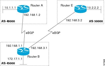
BGP is mainly used to connect a local network to an external network to gain access to the Internet or to connect to other organizations. When connecting to an external organization, external BGP (eBGP) peering sessions are created. Although BGP is referred to as an exterior gateway protocol (EGP), many networks within an organization are becoming so complex that BGP 
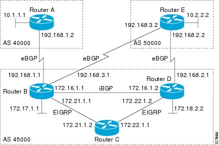
can be used to simplify the internal network used within the organization. BGP peers within the same organization exchange routing information through internal BGP (iBGP) peering sessions.
BGP uses a path-vector routing algorithm to exchange network reachability information with other BGP-speaking networking devices. Network reachability information is exchanged between BGP peers in routing updates. Network reachability information contains the network number, path-specific attributes, and the list of autonomous system numbers that a route must transit to reach a destination network. This list is contained in the AS-path attribute. BGP prevents routing loops by rejecting any routing update that contains the local autonomous system number because this indicates that the route has already traveled through that autonomous system and a loop would therefore be created. The BGP path-vector routing algorithm is a combination of the distance-vector routing algorithm and the AS-path loop detection.
BGP selects a single path, by default, as the best path to a destination host or network. The best path selection algorithm analyzes path attributes to determine which route is installed as the best path in the BGP routing table. Each path carries well-known mandatory, well-known discretionary, and optional transitive attributes that are used in BGP best path analysis. Cisco software provides the ability to influence BGP path selection by altering some of these attributes using the command-line interface (CLI.) BGP path selection can also be influenced through standard BGP policy configuration. For more details about using BGP to influence path selection and configuring BGP policies to filter traffic, see the “BGP 4 Prefix Filter and Inbound Route Maps” module and the “BGP Prefix-Based Outbound Route Filtering” module.
BGP uses the best-path selection algorithm to find a set of equally good routes. These routes are the potential multipaths. In Cisco IOS Release 12.2(33)SRD and later releases, when there are more equally good multipaths available than the maximum permitted number, the oldest paths are selected as multipaths.
BGP can be used to help manage complex internal networks by interfacing with Interior Gateway Protocols (IGPs). Internal BGP can help with issues such as scaling the existing IGPs to match the traffic demands while maintaining network efficiency.
Note
BGP requires more configuration than other routing protocols and the effects of any configuration changes must be fully understood. Incorrect configuration can create routing loops and negatively impact normal network operation.
BGP Router ID
BGP uses a router ID to identify BGP-speaking peers. The BGP router ID is a 32-bit value that is often represented by an IPv4 address. By default, the Cisco software sets the router ID to the IPv4 address of a loopback interface on the router. If no loopback interface is configured on the device, the software chooses the highest IPv4 address configured on a physical interface of the device to represent the BGP router ID. The BGP router ID must be unique to the BGP peers in a network.
BGP-Speaker and Peer Relationships
A BGP-speaking device does not discover another BGP-speaking device automatically. A network administrator usually manually configures the relationships between BGP-speaking devices. A peer device is a BGP-speaking device that has an active TCP connection to another BGP-speaking device. This relationship between BGP devices is often referred to as a neighbor, but because this can imply the idea that the BGP devices are directly connected with no other device in between, the term
neighbor will be avoided whenever possible in this document. A BGP speaker is the local device, and a peer is any other BGP-speaking network device.
When a TCP connection is established between peers, each BGP peer initially exchanges all its routes—the complete BGP routing table—with the other peer. After this initial exchange, only incremental updates are sent when there has been a topology change in the network, or when a routing policy has been implemented or modified. In the periods of inactivity between these updates, peers exchange special messages called keepalives.
A BGP autonomous system is a network that is controlled by a single technical administration entity. Peer devices are called external peers when they are in different autonomous systems and internal peers when they are in the same autonomous system. Usually, external peers are adjacent and share a subnet; internal peers may be anywhere in the same autonomous system.
BGP Peer Session Establishment
When a BGP routing process establishes a peering session with a peer, it goes through the following state changes:
Idle—The initial state that the BGP routing process enters when the routing process is enabled or when the device is reset. In this state, the device waits for a start event, such as a peering configuration with a remote peer. After the device receives a TCP connection request from a remote peer, the device initiates another start event to wait for a timer before starting a TCP connection to a remote peer. If the device is reset, the peer is reset and the BGP routing process returns to the Idle state.
Connect—The BGP routing process detects that a peer is trying to establish a TCP session with the local BGP speaker.
Active—In this state, the BGP routing process tries to establish a TCP session with a peer device using the ConnectRetry timer. Start events are ignored while the BGP routing process is in the Active state. If the BGP routing process is reconfigured or if an error occurs, the BGP routing process will release system resources and return to an Idle state.
OpenSent—The TCP connection is established, and the BGP routing process sends an OPEN message to the remote peer, and transitions to the OpenSent state. The BGP routing process can receive other OPEN messages in this state. If the connection fails, the BGP routing process transitions to the Active state.
OpenReceive—The BGP routing process receives the OPEN message from the remote peer and waits for an initial keepalive message from the remote peer. When a keepalive message is received, the BGP routing process transitions to the Established state. If a notification message is received, the BGP routing process transitions to the Idle state. If an error or configuration change occurs that affects the peering session, the BGP routing process sends a notification message with the Finite State Machine (FSM) error code and then transitions to the Idle state.
Established—The initial keepalive is received from the remote peer. Peering is now established with the remote neighbor and the BGP routing process starts exchanging update message with the remote peer. The hold timer restarts when an update or keepalive message is received. If the BGP process receives an error notification, it will transition to the Idle state.
BGP Session Reset
Whenever the routing policy changes due to a configuration change, BGP peering sessions must be reset by using the
clearipbgp command. Cisco software supports the following three mechanisms to reset BGP peering sessions:
Hard reset—A hard reset tears down the specified peering sessions including the TCP connection and deletes routes coming from the specified peer.
Soft reset—A soft reset uses stored prefix information to reconfigure and activate BGP routing tables without tearing down existing peering sessions. Soft reconfiguration uses stored update information, at the cost of additional memory for storing the updates, to allow you to apply new BGP policy without disrupting the network. Soft reconfiguration can be configured for inbound or outbound sessions.
Dynamic inbound soft reset—The route refresh capability, as defined in RFC 2918, allows the local device to reset inbound routing tables dynamically by exchanging route refresh requests to supporting peers. The route refresh capability does not store update information locally for nondisruptive policy changes. It instead relies on dynamic exchange with supporting peers. Route refresh must first be advertised through BGP capability negotiation between peers. All BGP devices must support the route refresh capability. To determine if a BGP device supports this capability, use the
showipbgpneighbors command. The following message is displayed in the output when the device supports the route refresh capability:
Received route refresh capability from peer.
The
bgpsoft-reconfig-backup command was introduced to configure BGP to perform inbound soft reconfiguration for peers that do not support the route refresh capability. The configuration of this command allows you to configure BGP to store updates (soft reconfiguration) only as necessary. Peers that support the route refresh capability are unaffected by the configuration of this command.
BGP Route Aggregation
BGP peers store and exchange routing information and the amount of routing information increases as more BGP speakers are configured. The use of route aggregation reduces the amount of information involved. Aggregation is the process of combining the attributes of several different routes so that only a single route is advertised. Aggregate prefixes use the classless interdomain routing (CIDR) principle to combine contiguous networks into one classless set of IP addresses that can be summarized in routing tables. Fewer routes now need to be advertised.
Two methods are available in BGP to implement route aggregation. You can redistribute an aggregated route into BGP or you can use a form of conditional aggregation. Basic route redistribution involves creating an aggregate route and then redistributing the routes into BGP. Conditional aggregation involves creating an aggregate route and then advertising or suppressing the advertising of certain routes on the basis of route maps, autonomous system set path (AS-SET) information, or summary information.
The bgpsuppress-inactive command configures BGP to not advertise inactive routes to any BGP peer. A BGP routing process can advertise routes that are not installed in the routing information database (RIB) to BGP peers by default. A route that is not installed into the RIB is an inactive route. Inactive route advertisement can occur, for example, when routes are advertised through common route aggregation. Inactive route advertisements can be suppressed to provide more consistent data forwarding.
BGP Route Aggregation Generating AS_SET Information
AS_SET information can be generated when BGP routes are aggregated using the
aggregate-address command. The path advertised for such a route is an AS_SET consisting of all the elements, including the communities, contained in all the paths that are being summarized. If the AS_PATHs to be aggregated are identical, only the AS_PATH is advertised. The ATOMIC-AGGREGATE attribute, set by default for the
aggregate-address command, is not added to the AS_SET.
Routing Policy Change Management
Routing policies for a peer include all the configurations for elements such as a route map, distribute list, prefix list, and filter list that may impact inbound or outbound routing table updates. Whenever there is a change in the routing policy, the BGP session must be soft-cleared, or soft-reset, for the new policy to take effect. Performing inbound reset enables the new inbound policy configured on the device to take effect. Performing outbound reset causes the new local outbound policy configured on the device to take effect without resetting the BGP session. As a new set of updates is sent during outbound policy reset, a new inbound policy of the neighbor can also take effect. This means that after changing inbound policy, you must do an inbound reset on the local device or an outbound reset on the peer device. Outbound policy changes require an outbound reset on the local device or an inbound reset on the peer device.
There are two types of reset: hard reset and soft reset. The table below lists their advantages and disadvantages.
Table 1 Advantages and Disadvantages of Hard and Soft Resets
Type of Reset
Advantages
Disadvantages
Hard reset
No memory overhead.
The prefixes in the BGP, IP, and Forwarding Information Base (FIB) tables provided by the neighbor are lost. A hard reset is not recommended.
Outbound soft reset
No configuration, and no storing of routing table updates.
Does not reset inbound routing table updates.
Dynamic inbound soft reset
Does not clear the BGP session and cache.
Does not require storing of routing table updates, and has no memory overhead.
Both BGP devices must support the route refresh capability.
Note
Does not reset outbound routing table updates.
Configured inbound soft reset (uses the
neighborsoft-reconfiguration router configuration command)
Can be used when both BGP devices do not support the automatic route refresh capability.
The
bgpsoft-reconfig-backup command was introduced to configure inbound soft reconfiguration for peers that do not support the route refresh capability.
Requires preconfiguration.
Stores all received (inbound) routing policy updates without modification; is memory-intensive.
Recommended only when absolutely necessary, such as when both BGP devices do not support the automatic route refresh capability.
Note
Does not reset outbound routing table updates.
Once you have defined two devices to be BGP neighbors, they will form a BGP connection and exchange routing information. If you subsequently change a BGP filter, weight, distance, version, or timer, or if you make a similar configuration change, you must reset BGP connections in order for the configuration change to take effect.
A soft reset updates the routing table for inbound and outbound routing updates. Cisco software supports soft reset without any prior configuration. This soft reset allows the dynamic exchange of route refresh requests and routing information between BGP devices, and allows the subsequent readvertisement of the respective outbound routing table. There are two types of soft reset:
When soft reset is used to generate inbound updates from a neighbor, it is called dynamic inbound soft reset.
When soft reset is used to send a new set of updates to a neighbor, it is called outbound soft reset.
To use soft reset without preconfiguration, both BGP peers must support the soft route refresh capability, which is advertised in the OPEN message sent when the peers establish a TCP session.
BGP Peer Groups
Often, in a BGP network, many neighbors are configured with the same update policies (that is, the same outbound route maps, distribute lists, filter lists, update source, and so on). Neighbors with the same update policies can be grouped into BGP peer groups to simplify configuration and, more importantly, to make configuration updates more efficient. When you have many peers, this approach is highly recommended.
BGP Backdoor Routes
In a BGP network topology with two border devices using eBGP to communicate to a number of different autonomous systems, using eBGP to communicate between the two border devices may not be the most efficient routing method. In the figure below, Router B as a BGP speaker will receive a route to Router D through eBGP, but this route will traverse at least two autonomous systems. Router B and Router D are also connected through an Enhanced Interior Gateway Routing Protocol (EIGRP) network (any IGP can be used here), and this route has a shorter path. EIGRP routes, however, have a default administrative distance of 90, and eBGP routes have a default administrative distance of 20, so BGP will prefer the eBGP route. Changing the default administrative distances is not recommended because changing the administrative distance may lead to routing loops. To cause BGP to prefer the EIGRP route, you can use the
networkbackdoor command. BGP treats the network specified by the
networkbackdoor command as a locally assigned network, except that it does not advertise the specified network in BGP updates. In the figure below, this means that Router B will communicate to Router D using the shorter EIGRP route instead of the longer eBGP route.
Figure 1. BGP Backdoor Route Topology
How to Configure BGP 4
Configuring a basic BGP network consists of a few required tasks and many optional tasks. A BGP routing process must be configured and BGP peers must be configured, preferably using the address family configuration model. If the BGP peers are part of a VPN network, the BGP peers must be configured using the IPv4 VRF address family task.
Perform this task to configure a BGP routing process. You must perform the required steps at least once to enable BGP. The optional steps here allow you to configure additional features in your BGP network. Several of the features, such as logging neighbor resets and immediate reset of a peer when its link goes down, are enabled by default but are presented here to enhance your understanding of how your BGP network operates.
Note
A device that runs Cisco software can be configured to run only one BGP routing process and to be a member of only one BGP autonomous system. However, a BGP routing process and autonomous system can support multiple concurrent BGP address family and subaddress family configurations.
The configuration in this task is done at Router A in the figure below and would need to be repeated with appropriate changes to the IP addresses (for example, at Router B) to fully achieve a BGP process between the two devices. No address family is configured here for the BGP routing process, so routing information for the IPv4 unicast address family is advertised by default.
Figure 2. BGP Topology with Two Autonomous Systems
(Optional) Specifies a network as local to this autonomous system and adds it to the BGP routing table.
For exterior protocols, the
network command controls which networks are advertised. Interior protocols use the
network command to determine where to send updates.
Step 5
bgprouter-idip-address
Example:
Device(config-router)# bgp router-id 10.1.1.99
(Optional) Configures a fixed 32-bit router ID as the identifier of the local device running BGP.
Use the
ip-address argument to specify a unique router ID within the network.
Note
Configuring a router ID using the
bgprouter-id command resets all active BGP peering sessions.
Step 6
timersbgpkeepaliveholdtime
Example:
Device(config-router)# timers bgp 70 120
(Optional) Sets BGP network timers.
Use the
keepalive argument to specify the frequency, in seconds, with which the software sends keepalive messages to its BGP peer. By default, the keepalive timer is set to 60 seconds.
Use the
holdtime argument to specify the interval, in seconds, after which the software, having not received a keepalive message, declares a BGP peer dead. By default, the holdtime timer is set to 180 seconds.
Step 7
bgpfast-external-fallover
Example:
Device(config-router)# bgp fast-external-fallover
(Optional) Enables the automatic resetting of BGP sessions.
By default, the BGP sessions of any directly adjacent external peers are reset if the link used to reach them goes down.
Step 8
bgplog-neighbor-changes
Example:
Device(config-router)# bgp log-neighbor-changes
(Optional) Enables logging of BGP neighbor status changes (up or down) and neighbor resets.
Use this command for troubleshooting network connectivity problems and measuring network stability. Unexpected neighbor resets might indicate high error rates or high packet loss in the network and should be investigated.
Step 9
end
Example:
Device(config-router)# end
Exits router configuration mode and enters privileged EXEC mode.
Step 10
showipbgp [network] [network-mask]
Example:
Device# show ip bgp
(Optional) Displays the entries in the BGP routing table.
Note
Only the syntax applicable to this task is used in this example. For more details, see the
Cisco IOS IP Routing: BGP Command Reference.
Examples
The following sample output from the
showipbgp command shows the BGP routing table for Router A in the figure above after this task has been configured on Router A. You can see an entry for the network 10.1.1.0 that is local to this autonomous system.
BGP table version is 12, local router ID is 10.1.1.99
Status codes: s suppressed, d damped, h history, * valid, > best, i - internal,
r RIB-failure, S Stale
Origin codes: i - IGP, e - EGP, ? - incomplete
Network Next Hop Metric LocPrf Weight Path
*> 10.1.1.0/24 0.0.0.0 0 32768 i
Troubleshooting Tips
Use the ping command to check basic network connectivity between the BGP routers.
Configuring a BGP Peer
Perform this task to configure BGP between two IPv4 devices (peers). The address family configured here is the default IPv4 unicast address family, and the configuration is done at Router A in the figure above. Remember to perform this task for any neighboring devices that are to be BGP peers.
Before You Begin
Before you perform this task, perform the “Configuring a BGP Routing Process” task.
Note
By default, neighbors that are defined using the
neighborremote-as command in router configuration mode exchange only IPv4 unicast address prefixes. To exchange other address prefix types, such as IPv6 prefixes, neighbors must also be activated using the
neighboractivate command in address family configuration mode for the other prefix types, such as IPv6 prefixes.
Specifies the IPv4 address family and enters address family configuration mode.
The
unicast keyword specifies the IPv4 unicast address family. By default, the device is placed in configuration mode for the IPv4 unicast address family if the
unicast keyword is not specified with the
address-familyipv4 command.
The
multicast keyword specifies IPv4 multicast address prefixes.
The
vrf keyword and
vrf-name argument specify the name of the virtual routing and forwarding (VRF) instance to associate with subsequent IPv4 address family configuration mode commands.
Enables the neighbor to exchange prefixes for the IPv4 unicast address family with the local device.
Step 7
end
Example:
Device(config-router-af)# end
Exits address family configuration mode and returns to privileged EXEC mode.
Step 8
showipbgp[network] [network-mask]
Example:
Device# show ip bgp
(Optional) Displays the entries in the BGP routing table.
Note
Only the syntax applicable to this task is used in this example. For more details, see the
Cisco IOS IP Routing: BGP Command Reference.
Step 9
showipbgpneighbors[neighbor-address]
Example:
Device(config-router-af)# show ip bgp neighbors 192.168.2.2
(Optional) Displays information about the TCP and BGP connections to neighbors.
Note
Only the syntax applicable to this task is used in this example. For more details, see the
Cisco IOS IP Routing: BGP Command Reference.
Examples
The following sample output from the
showipbgp command shows the BGP routing table for Router A in the figure above after this task has been configured on Router A and Router B. You can now see an entry for the network 172.17.1.0 in autonomous system 45000.
BGP table version is 13, local router ID is 10.1.1.99
Status codes: s suppressed, d damped, h history, * valid, > best, i - internal,
r RIB-failure, S Stale
Origin codes: i - IGP, e - EGP, ? - incomplete
Network Next Hop Metric LocPrf Weight Path
*> 10.1.1.0/24 0.0.0.0 0 32768 i
*> 172.17.1.0/24 192.168.1.1 0 0 45000 i
The following sample output from the
showipbgpneighbors command shows information about the TCP and BGP connections to the BGP neighbor 192.168.1.1 of Router A in the figure above after this task has been configured on Router A:
BGP neighbor is 192.168.1.1, remote AS 45000, external link
BGP version 4, remote router ID 172.17.1.99
BGP state = Established, up for 00:06:55
Last read 00:00:15, last write 00:00:15, hold time is 120, keepalive intervals
Configured hold time is 120,keepalive interval is 70 seconds, Minimum holdtims
Neighbor capabilities:
Route refresh: advertised and received (old & new)
Address family IPv4 Unicast: advertised and received
Message statistics:
InQ depth is 0
OutQ depth is 0
Sent Rcvd
Opens: 1 1
Notifications: 0 0
Updates: 1 2
Keepalives: 13 13
Route Refresh: 0 0
Total: 15 16
Default minimum time between advertisement runs is 30 seconds
For address family: IPv4 Unicast
BGP table version 13, neighbor version 13/0
Output queue size : 0
Index 1, Offset 0, Mask 0x2
1 update-group member
Sent Rcvd
Prefix activity: ---- ----
Prefixes Current: 1 1 (Consumes 52 bytes)
Prefixes Total: 1 1
Implicit Withdraw: 0 0
Explicit Withdraw: 0 0
Used as bestpath: n/a 1
Used as multipath: n/a 0
Outbound Inbound
Local Policy Denied Prefixes: -------- -------
AS_PATH loop: n/a 1
Bestpath from this peer: 1 n/a
Total: 1 1
Number of NLRIs in the update sent: max 0, min 0
Connections established 1; dropped 0
Last reset never
Connection state is ESTAB, I/O status: 1, unread input bytes: 0
Connection is ECN Disabled
Local host: 192.168.1.2, Local port: 179
Foreign host: 192.168.1.1, Foreign port: 37725
Enqueued packets for retransmit: 0, input: 0 mis-ordered: 0 (0 bytes)
Event Timers (current time is 0x12F4F2C):
Timer Starts Wakeups Next
Retrans 14 0 0x0
TimeWait 0 0 0x0
AckHold 13 8 0x0
SendWnd 0 0 0x0
KeepAlive 0 0 0x0
GiveUp 0 0 0x0
PmtuAger 0 0 0x0
DeadWait 0 0 0x0
iss: 165379618 snduna: 165379963 sndnxt: 165379963 sndwnd: 16040
irs: 3127821601 rcvnxt: 3127821993 rcvwnd: 15993 delrcvwnd: 391
SRTT: 254 ms, RTTO: 619 ms, RTV: 365 ms, KRTT: 0 ms
minRTT: 12 ms, maxRTT: 300 ms, ACK hold: 200 ms
Flags: passive open, nagle, gen tcbs
IP Precedence value : 6
Datagrams (max data segment is 1460 bytes):
Rcvd: 20 (out of order: 0), with data: 15, total data bytes: 391
Sent: 22 (retransmit: 0, fastretransmit: 0, partialack: 0, Second Congestion: 04
Troubleshooting Tips
Use the ping command to verify basic network connectivity between the BGP routers.
Configuring a BGP Peer for the IPv4 VRF Address Family
Perform this optional task to configure BGP between two IPv4 devices (peers) that must exchange IPv4 VRF information because they exist in a VPN. The address family configured here is the IPv4 VRF address family, and the configuration is done at Router B in the figure below with the neighbor 192.168.3.2 at Router E in autonomous system 50000. Remember to perform this task for any neighboring devices that are to be BGP IPv4 VRF address family peers.
Figure 3. BGP Topology for IPv4 VRF Address Family
Before You Begin
Before you perform this task, perform the “Configuring a BGP Routing Process” task.
Creates a route target extended community for a VRF.
Use the
import keyword to import routing information from the target VPN extended community.
Use the
export keyword to export routing information to the target VPN extended community.
Use the
both keyword to import both import and export routing information to the target VPN extended community.
Use the
route-target-ext-community argument to add the route target extended community attributes to the VRF's list of import, export, or both (import and export) route target extended communities.
Step 10
exit
Example:
Device(config-vrf)# exit
Exits VRF configuration mode and enters global configuration mode.
Step 11
routerbgpautonomous-system-number
Example:
Device(config)# router bgp 45000
Enters router configuration mode for the specified routing process.
Specifies the IPv4 address family and enters address family configuration mode.
Use the
unicast keyword to specify the IPv4 unicast address family. By default, the device is placed in configuration mode for the IPv4 unicast address family if the
unicast keyword is not specified with the
address-familyipv4 command.
Use the
multicast keyword to specify IPv4 multicast address prefixes.
Use the
vrf keyword and
vrf-name argument to specify the name of the VRF instance to associate with subsequent IPv4 address family configuration mode commands.
Controls how many prefixes can be received from a neighbor.
Use the
maximum argument to specify the maximum number of prefixes allowed from the specified neighbor. The number of prefixes that can be configured is limited only by the available system resources on a device.
Use the
threshold argument to specify an integer representing a percentage of the maximum prefix limit at which the device starts to generate a warning message.
Use the
warning-only keyword to allow the device to generate a log message when the maximum prefix limit is exceeded, instead of terminating the peering session.
Enables the neighbor to exchange prefixes for the IPv4 VRF address family with the local device.
Step 16
end
Example:
Device(config-router-af)# end
Exits address family configuration mode and enters privileged EXEC mode.
Troubleshooting Tips
Use the
pingvrf command to verify basic network connectivity between the BGP devices, and use the
showipvrf command to verify that the VRF instance has been created.
Customizing a BGP Peer
Perform this task to customize your BGP peers. Although many of the steps in this task are optional, this task demonstrates how the neighbor and address family configuration command relationships work. Using the example of the IPv4 multicast address family, neighbor address family-independent commands are configured before the IPv4 multicast address family is configured. Commands that are address family-dependent are then configured and the
exitaddress-family command is shown. An optional step shows how to disable a neighbor.
The configuration in this task is done at Router B in the figure below and would need to be repeated with appropriate changes to the IP addresses, for example, at Router E to fully configure a BGP process between the two devices.
Figure 4. BGP Peer Topology
Note
By default, neighbors that are defined using the
neighborremote-as command in router configuration mode exchange only IPv4 unicast address prefixes. To exchange other address prefix types, such as IPv6 prefixes, neighbors must also be activated using the
neighboractivate command in address family configuration mode for the other prefix types, such as IPv6 prefixes.
Enters router configuration mode for the specified routing process.
Step 4
nobgpdefaultipv4-unicast
Example:
Device(config-router)# no bgp default ipv4-unicast
Disables the IPv4 unicast address family for the BGP routing process.
Note
Routing information for the IPv4 unicast address family is advertised by default for each BGP routing session configured with the
neighborremote-as router configuration command unless you configure the
nobgpdefaultipv4-unicast router configuration command before configuring the
neighborremote-as command. Existing neighbor configurations are not affected.
Specifies the IPv4 address family and enters address family configuration mode.
The
unicast keyword specifies the IPv4 unicast address family. By default, the device is placed in configuration mode for the IPv4 unicast address family if the
unicast keyword is not specified with the
address-familyipv4 command.
The
multicast keyword specifies IPv4 multicast address prefixes.
The
vrf keyword and
vrf-name argument specify the name of the VRF instance to associate with subsequent IPv4 address family configuration mode commands.
(Optional) Specifies a network as local to this autonomous system and adds it to the BGP routing table.
For exterior protocols the
network command controls which networks are advertised. Interior protocols use the
network command to determine where to send updates.
(Optional) Displays information about the TCP and BGP connections to neighbors.
Examples
The following sample output from the
showipbgpipv4multicast command shows BGP IPv4 multicast information for Router B in the figure above after this task has been configured on Router B and Router E. Note that the networks local to each device that were configured under IPv4 multicast address family appear in the output table.
BGP table version is 3, local router ID is 172.17.1.99
Status codes: s suppressed, d damped, h history, * valid, > best, i - internal,
r RIB-failure, S Stale
Origin codes: i - IGP, e - EGP, ? - incomplete
Network Next Hop Metric LocPrf Weight Path
*> 10.2.2.0/24 192.168.3.2 0 0 50000 i
*> 172.17.1.0/24 0.0.0.0 0 32768 i
The following partial sample output from the
showipbgpneighbors command for neighbor 192.168.3.2 shows general BGP information and specific BGP IPv4 multicast address family information about the neighbor. The command was entered on Router B in the figure above after this task had been configured on Router B and Router E.
BGP neighbor is 192.168.3.2, remote AS 50000, external link
Description: finance
BGP version 4, remote router ID 10.2.2.99
BGP state = Established, up for 01:48:27
Last read 00:00:26, last write 00:00:26, hold time is 120, keepalive intervals
Configured hold time is 120,keepalive interval is 70 seconds, Minimum holdtims
Neighbor capabilities:
Route refresh: advertised and received (old & new)
Address family IPv4 Unicast: advertised
Address family IPv4 Multicast: advertised and received
!
For address family: IPv4 Multicast
BGP table version 3, neighbor version 3/0
Output queue size : 0
Index 1, Offset 0, Mask 0x2
1 update-group member
Uses NEXT_HOP attribute for MBGP NLRIs
Sent Rcvd
Prefix activity: ---- ----
Prefixes Current: 1 1 (Consumes 48 bytes)
Prefixes Total: 1 1
Implicit Withdraw: 0 0
Explicit Withdraw: 0 0
Used as bestpath: n/a 1
Used as multipath: n/a 0
Outbound Inbound
Local Policy Denied Prefixes: -------- -------
Bestpath from this peer: 1 n/a
Total: 1 0
Number of NLRIs in the update sent: max 0, min 0
Minimum time between advertisement runs is 25 seconds
Connections established 8; dropped 7
Last reset 01:48:54, due to User reset
Connection state is ESTAB, I/O status: 1, unread input bytes: 0
Connection is ECN Disabled
Local host: 192.168.3.1, Local port: 13172
Foreign host: 192.168.3.2, Foreign port: 179
!
Removing BGP Configuration Commands Using a Redistribution
BGP CLI configuration can become quite complex even in smaller BGP networks. If you need to remove any CLI configuration, you must consider all the implications of removing the CLI. Analyze the current running configuration to determine the current BGP neighbor relationships, any address family considerations, and even other routing protocols that are configured. Many BGP CLI commands affect other parts of the CLI configuration.
Perform this task to remove all the BGP configuration commands used in a redistribution of BGP routes into EIGRP. A route map can be used to match and set parameters or to filter the redistributed routes to ensure that routing loops are not created when these routes are subsequently advertised by EIGRP. When removing BGP configuration commands you must remember to remove or disable all the related commands. In this example, if the
route-map command is omitted, then the redistribution will still occur and possibly with unexpected results as the route map filtering has been removed. Omitting just the
redistribute command would mean that the route map is not applied, but it would leave unused commands in the running configuration.
For more details on BGP CLI removal, see the “BGP CLI Removal Considerations” concept in the “Cisco BGP Overview” module.
To view the redistribution configuration before and after the CLI removal, see the “Examples: Removing BGP Configuration Commands Using a Redistribution Example” section.
SUMMARY STEPS
1.enable
2.configureterminal
3.noroute-mapmap-name
4.routereigrpautonomous-system-number
5.noredistributeprotocol [as-number]
6.end
7.showrunning-config
DETAILED STEPS
Command or Action
Purpose
Step 1
enable
Example:
Device> enable
Enables privileged EXEC mode.
Enter your password if prompted.
Step 2
configureterminal
Example:
Device# configure terminal
Enters global configuration mode.
Step 3
noroute-mapmap-name
Example:
Device(config)# no route-map bgp-to-eigrp
Removes a route map from the running configuration.
In this example, a route map named bgp-to-eigrp is removed from the configuration.
Step 4
routereigrpautonomous-system-number
Example:
Device(config)# router eigrp 100
Enters router configuration mode for the specified routing process.
Step 5
noredistributeprotocol [as-number]
Example:
Device(config-router)# no redistribute bgp 45000
Disables the redistribution of routes from one routing domain into another routing domain.
In this example, the configuration of the redistribution of BGP routes into the EIGRP routing process is removed from the running configuration.
Note
If a route map was included in the original
redistribute command configuration, remember to remove the
route-map command configuration as in Step 3 in this example task.
Note
Only the syntax applicable to this task is used in this example. For more details, see the
Cisco IOS IP Routing: BGP Command Reference.
Step 6
end
Example:
Device(config-router)# end
Exits router configuration mode and enters privileged EXEC mode.
Step 7
showrunning-config
Example:
Device# show running-config
(Optional) Displays the current running configuration on the router.
Use this command to verify that the
redistribute and
route-map commands are removed from the router configuration.
Monitoring and Maintaining Basic BGP
The tasks in this section are concerned with the resetting and display of information about basic BGP processes and peer relationships. Once you have defined two devices to be BGP neighbors, they will form a BGP connection and exchange routing information. If you subsequently change a BGP filter, weight, distance, version, or timer, or make a similar configuration change, you may have to reset BGP connections for the configuration change to take effect.
Configuring Inbound Soft Reconfiguration When Route Refresh Capability Is Missing
Perform this task to configure inbound soft reconfiguration using the
bgpsoft-reconfig-backup command for BGP peers that do not support the route refresh capability. BGP peers that support the route refresh capability are unaffected by the configuration of this command. Note that the memory requirements for storing the inbound update information can become quite large.
Enters router configuration mode for the specified routing process.
Step 4
bgplog-neighbor-changes
Example:
Device(config-router)# bgp log-neighbor-changes
Enables logging of BGP neighbor resets.
Step 5
bgpsoft-reconfig-backup
Example:
Device(config-router)# bgp soft-reconfig-backup
Configures a BGP speaker to perform inbound soft reconfiguration for peers that do not support the route refresh capability.
This command is used to configure BGP to perform inbound soft reconfiguration for peers that do not support the route refresh capability. The configuration of this command allows you to configure BGP to store updates (soft reconfiguration) only as necessary. Peers that support the route refresh capability are unaffected by the configuration of this command.
Configures the Cisco software to start storing updates.
All the updates received from this neighbor will be stored unmodified, regardless of the inbound policy. When inbound soft reconfiguration is done later, the stored information will be used to generate a new set of inbound updates.
Configures a route map and enters route-map configuration mode.
In this example, a route map named LOCAL is created.
Step 12
setlocal-preferencenumber-value
Example:
Device(config-route-map)# set local-preference 200
Specifies a preference value for the autonomous system path.
In this example, the local preference value is set to 200.
Step 13
end
Example:
Device(config-route-map)# end
Exits route-map configuration mode and enters privileged EXEC mode.
Step 14
showipbgpneighbors [neighbor-address]
Example:
Device# show ip bgp neighbors 192.168.1.2
(Optional) Displays information about the TCP and BGP connections to neighbors.
Note
Only the syntax applicable to this task is used in this example. For more details, see the
Cisco IOS IP Routing: BGP Command Reference.
Step 15
showipbgp [network] [network-mask]
Example:
Device# show ip bgp
(Optional) Displays the entries in the BGP routing table.
Note
Only the syntax applicable to this task is used in this example. For more details, see the
Cisco IOS IP Routing: BGP Command Reference.
Examples
The following partial output from the
showipbgpneighbors command shows information about the TCP and BGP connections to the BGP neighbor 192.168.2.1. This peer supports route refresh.
BGP neighbor is 192.168.1.2, remote AS 40000, external link
Neighbor capabilities:
Route refresh: advertised and received(new)
The following partial output from the
showipbgpneighbors command shows information about the TCP and BGP connections to the BGP neighbor 192.168.3.2. This peer does not support route refresh so the soft-reconfig inbound paths for BGP peer 192.168.3.2 will be stored because there is no other way to update any inbound policy updates.
BGP neighbor is 192.168.3.2, remote AS 50000, external link
Neighbor capabilities:
Route refresh: advertised
The following sample output from the
showipbgp command shows the entry for the network 172.17.1.0. Both BGP peers are advertising 172.17.1.0/24, but only the received-only path is stored for 192.168.3.2.
BGP routing table entry for 172.17.1.0/24, version 11
Paths: (3 available, best #3, table Default-IP-Routing-Table, RIB-failure(4))
Flag: 0x820
Advertised to update-groups:
1
50000
192.168.3.2 from 192.168.3.2 (172.17.1.0)
Origin incomplete, metric 0, localpref 200, valid, external
50000, (received-only)
192.168.3.2 from 192.168.3.2 (172.17.1.0)
Origin incomplete, metric 0, localpref 100, valid, external
40000
192.168.1.2 from 192.168.1.2 (172.16.1.0)
Origin incomplete, metric 0, localpref 200, valid, external, best
Resetting and Displaying Basic BGP Information
Perform this task to reset and display information about basic BGP processes and peer relationships.
Displays information about the TCP and BGP connections to neighbors.
In the example provided, the routes advertised from the device to BGP neighbor 192.168.3.2 on another device are displayed.
Step 5
showipbgppaths
Example:
Device# showipbgppaths
Displays information about all the BGP paths in the database.
Step 6
showipbgpsummary
Example:
Device# showipbgpsummary
Displays information about the status of all BGP connections.
Aggregating Route Prefixes Using BGP
BGP peers exchange information about local networks, but this can quickly lead to large BGP routing tables. CIDR enables the creation of aggregate routes (or
supernets) to minimize the size of routing tables. Smaller BGP routing tables can reduce the convergence time of the network and improve network performance. Aggregated routes can be configured and advertised using BGP. Some aggregations advertise only summary routes and other methods of aggregating routes allow more specific routes to be forwarded. Aggregation applies only to routes that exist in the BGP routing table. An aggregated route is forwarded if at least one more specific route of the aggregation exists in the BGP routing table. Perform one of the following tasks to aggregate routes within BGP:
Use this task to redistribute a static aggregate route into BPG. A static aggregate route is configured and then redistributed into the BGP routing table. The static route must be configured to point to interface null 0 and the prefix should be a superset of known BGP routes. When a device receives a BGP packet, it will use the more specific BGP routes. If the route is not found in the BGP routing table, then the packet will be forwarded to null 0 and discarded.
Device(config)# ip route 172.0.0.0 255.0.0.0 null 0
Creates a static route.
Step 4
routerbgpautonomous-system-number
Example:
Device(config)# router bgp 45000
Enters router configuration mode for the specified routing process.
Step 5
redistributestatic
Example:
Device(config-router)# redistribute static
Redistributes routes into the BGP routing table.
Step 6
end
Example:
Device(config-router)# end
Exits router configuration mode and returns to privileged EXEC mode.
Configuring Conditional Aggregate Routes Using BGP
Use this task to create an aggregate route entry in the BGP routing table when at least one specific route falls into the specified range. The aggregate route is advertised as originating from your autonomous system. For more information, see the “BGP Route Aggregation Generating AS_SET Information” section.
SUMMARY STEPS
1.enable
2.configureterminal
3.routerbgpautonomous-system-number
4.aggregate-addressaddressmask [as-set]
5.end
DETAILED STEPS
Command or Action
Purpose
Step 1
enable
Example:
Device> enable
Enables privileged EXEC mode.
Enter your password if prompted.
Step 2
configureterminal
Example:
Device# configure terminal
Enters global configuration mode.
Step 3
routerbgpautonomous-system-number
Example:
Device(config)# router bgp 45000
Enters router configuration mode for the specified routing process.
Creates an aggregate entry in a BGP routing table.
A specified route must exist in the BGP table.
Use the
aggregate-address command with no keywords to create an aggregate entry if any more-specific BGP routes are available that fall in the specified range.
Use the
as-set keyword to specify that the path advertised for this route is an AS_SET. Do not use the
as-set keyword when aggregating many paths because this route is withdrawn and updated every time the reachability information for the aggregated route changes.
Note
Only partial syntax is used in this example. For more details, see the
Cisco IOS IP Routing: BGP Command Reference.
Step 5
end
Example:
Device(config-router)# end
Exits router configuration mode and enters privileged EXEC mode.
Suppressing and Unsuppressing the Advertisement of Aggregated Routes Using BGP
Use this task to create an aggregate route, suppress the advertisement of routes using BGP, and subsequently unsuppress the advertisement of routes. Routes that are suppressed are not advertised to any neighbors, but it is possible to unsuppress routes that were previously suppressed to specific neighbors.
Use the optional
summary-only keyword to create the aggregate route (for example, 10.*.*.*) and also suppresses advertisements of more-specific routes to all neighbors.
Use the optional
suppress-map keyword to create the aggregate route but suppress advertisement of specified routes. Routes that are suppressed are not advertised to any neighbors. You can use the
match clauses of route maps to selectively suppress some more-specific routes of the aggregate and leave others unsuppressed. IP access lists and autonomous system path access lists
match clauses are supported.
Note
Only partial syntax is used in this example. For more details, see the
Cisco IOS IP Routing: BGP Command Reference.
(Optional) Selectively advertises routes previously suppressed by the
aggregate-address command.
In this example, the routes previously suppressed in Step 5 are advertised to neighbor 192.168.1.2.
Step 7
end
Example:
Device(config-router)# end
Exits router configuration mode and enters privileged EXEC mode.
Conditionally Advertising BGP Routes
Perform this task to conditionally advertise selected BGP routes. The routes or prefixes that will be conditionally advertised are defined in two route maps: an advertise map and either an exist map or nonexist map. The route map associated with the exist map or nonexist map specifies the prefix that the BGP speaker will track. The route map associated with the advertise map specifies the prefix that will be advertised to the specified neighbor when the condition is met.
If a prefix is found to be present in the exist map by the BGP speaker, the prefix specified by the advertise map is advertised.
If a prefix is found not to be present in the nonexist map by the BGP speaker, the prefix specified by the advertise map is advertised.
If the condition is not met, the route is withdrawn and conditional advertisement does not occur. All routes that may be dynamically advertised or not advertised must exist in the BGP routing table in order for conditional advertisement to occur. These routes are referenced from an access list or an IP prefix list.
Adds the IP address of the neighbor in the specified autonomous system to the IPv4 multiprotocol BGP neighbor table of the local device.
In this example, the prefix (172.17.0.0) matching the ACL in the advertise map (the route map named map1) will be advertised to the neighbor only when a prefix (192.168.50.0) matching the ACL in exist map (the route-map named map2) is in the local BGP table.
Step 6
exit
Example:
Device(config-router)# exit
Exits router configuration mode and enters global configuration mode.
Step 7
route-mapmap-tag[permit |deny] [sequence-number]
Example:
Device(config)# route-map map1 permit 10
Configures a route map and enters route map configuration mode.
In this example, a route map named map1 is created.
In this example, access list 2 permits the 192.168.50.0 to be the prefix of the exist-map.
Step 15
exit
Example:
Device(config)# exit
Exits global configuration mode and returns to privileged EXEC mode.
Originating BGP Routes
Route aggregation is useful to minimize the size of the BGP table, but there are situations when you want to add more specific prefixes to the BGP table. Route aggregation can hide more specific routes. Using the
network command as shown in the “Configuring a BGP Routing Process” section originates routes, and the following optional tasks originate BGP routes for the BGP table for different situations.
Perform this task to advertise a default route to BGP peers. The default route is locally originated. A default route can be useful to simplify configuration or to prevent the device from using too many system resources. If the device is peered with an Internet service provider (ISP), the ISP will carry full routing tables, so configuring a default route into the ISP network saves resources at the local device.
(Optional) Permits a BGP speaker--the local device--to send the default route 0.0.0.0 to a peer for use as a default route.
Step 9
end
Example:
Device(config-router)# end
Exits router configuration mode and enters privileged EXEC mode.
Originating BGP Routes Using Backdoor Routes
Use this task to indicate to border devices which networks are reachable using a backdoor route. A backdoor network is treated the same as a local network, except that it is not advertised. For more information, see the BGP Backdoor Routes section.
Before You Begin
This task assumes that the IGP (EIGRP, in this example) is already configured for the BGP peers. The configuration is done at Router B in the figure in the “BGP Backdoor Routes” section, and the BGP peer is Router D.
Indicates a network that is reachable through a backdoor route.
Step 6
end
Example:
Device(config-router)# end
Exits router configuration mode and returns to privileged EXEC mode.
Configuring a BGP Peer Group
This task explains how to configure a BGP peer group. Often, in a BGP speaker, many neighbors are configured with the same update policies (that is, the same outbound route maps, distribute lists, filter lists, update source, and so on). Neighbors with the same update policies can be grouped into peer groups to simplify configuration and, more importantly, to make updating more efficient. When you have many peers, this approach is highly recommended.
The three steps to configure a BGP peer group, described in the following task, are as follows:
Creating the peer group
Assigning options to the peer group
Making neighbors members of the peer group
You can disable a BGP peer or peer group without removing all the configuration information using the
neighborshutdown router configuration command.
Note
By default, neighbors that are defined using the
neighborremote-as command in router configuration mode exchange only IPv4 unicast address prefixes. To exchange other address prefix types, such as IPv6 prefixes, neighbors must also be activated using the
neighboractivate command in address family configuration mode for the other prefix types.
Enables the neighbor to exchange prefixes for the IPv4 address family with the local device.
Note
By default, neighbors that are defined using the
neighborremote-as command in router configuration mode exchange only unicast address prefixes. To allow BGP to exchange other address prefix types, such as multicast that is configured in this example, neighbors must also be activated using the
neighboractivate command.
Example: Configuring a BGP Process and Customizing Peers
The following example shows the configuration for Router B in the figure above (in the “Customizing a BGP Peer” section) with a BGP process configured with two neighbor peers (at Router A and at Router E) in separate autonomous systems. IPv4 unicast routes are exchanged with both peers and IPv4 multicast routes are exchanged with the BGP peer at Router E.
Examples: Removing BGP Configuration Commands Using a Redistribution Example
The following examples show first the CLI configuration to enable the redistribution of BGP routes into EIGRP using a route map and then the CLI configuration to remove the redistribution and route map. Some BGP configuration commands can affect other CLI commands and this example demonstrates how the removal of one command affects another command.
In the first configuration example, a route map is configured to match and set autonomous system numbers. BGP neighbors in three different autonomous systems are configured and activated. An EIGRP routing process is started, and the redistribution of BGP routes into EIGRP using the route map is configured.
In the second configuration example, both the
route-map command and the
redistribute command are disabled. If only the route-map command is removed, it does not automatically disable the redistribution. The redistribution will now occur without any matching or filtering. To remove the redistribution configuration, the
redistribute command must also be disabled.
CLI to Remove BGP Route Redistribution Into EIGRP
configure terminal
no route-map bgp-to-eigrp
router eigrp 100
no redistribute bgp 45000
end
Examples: BGP Soft Reset
The following examples show two ways to reset the connection for BGP peer 192.168.1.1.
Example: Dynamic Inbound Soft Reset
The following example shows the command used to initiate a dynamic soft reconfiguration in the BGP peer 192.168.1.1. This command requires that the peer support the route refresh capability.
clear ip bgp 192.168.1.1 soft in
Example: Inbound Soft Reset Using Stored Information
The following example shows how to enable inbound soft reconfiguration for the neighbor 192.168.1.1. All the updates received from this neighbor will be stored unmodified, regardless of the inbound policy. When inbound soft reconfiguration is performed later, the stored information will be used to generate a new set of inbound updates.
The following example clears the session with the neighbor 192.168.1.1:
clear ip bgp 192.168.1.1 soft in
Example: Resetting and Displaying Basic BGP Information
The following example shows how to reset and display basic BGP information.
The
clearipbgp* command clears and resets all the BGP neighbor sessions. Specific neighbors or all peers in an autonomous system can be cleared by using the
neighbor-address and
autonomous-system-number arguments. If no argument is specified, this command will clear and reset all BGP neighbor sessions.
Note
The
clearipbgp* command also clears all the internal BGP structures, which makes it useful as a troubleshooting tool.
Device# clear ip bgp *
The
showipbgp command is used to display all the entries in the BGP routing table. The following example displays BGP routing table information for the 10.1.1.0 network:
Device# show ip bgp 10.1.1.0 255.255.255.0
BGP routing table entry for 10.1.1.0/24, version 2
Paths: (1 available, best #1, table Default-IP-Routing-Table)
Advertised to update-groups:
1
40000
192.168.1.2 from 192.168.1.2 (10.1.1.99)
Origin IGP, metric 0, localpref 100, valid, external, best
The
showipbgpneighbors command is used to display information about the TCP and BGP connections to neighbors. The following example displays the routes that were advertised from Router B in the figure above (in the “Configuring a BGP Peer for the IPv4 VRF Address Family” section) to its BGP neighbor 192.168.3.2 on Router E:
Device# show ip bgp neighbors 192.168.3.2 advertised-routes
BGP table version is 3, local router ID is 172.17.1.99
Status codes: s suppressed, d damped, h history, * valid, > best, i - internal,
r RIB-failure, S Stale
Origin codes: i - IGP, e - EGP, ? - incomplete
Network Next Hop Metric LocPrf Weight Path
*> 10.1.1.0/24 192.168.1.2 0 0 40000 i
*> 172.17.1.0/24 0.0.0.0 0 32768 i
Total number of prefixes 2
The
showipbgppaths command is used to display all the BGP paths in the database. The following example displays BGP path information for Router B in the figure above (in the “Customizing a BGP Peer” section):
Device# show ip bgp paths
Address Hash Refcount Metric Path
0x2FB5DB0 0 5 0 i
0x2FB5C90 1 4 0 i
0x2FB5C00 1361 2 0 50000 i
0x2FB5D20 2625 2 0 40000 i
The
showipbgpsummary command is used to display the status of all BGP connections. The following example displays BGP routing table information for Router B in the figure above (in the “Customizing a BGP Peer” section):
Device# show ip bgp summary
BGP router identifier 172.17.1.99, local AS number 45000
BGP table version is 3, main routing table version 3
2 network entries using 234 bytes of memory
2 path entries using 104 bytes of memory
4/2 BGP path/bestpath attribute entries using 496 bytes of memory
2 BGP AS-PATH entries using 48 bytes of memory
0 BGP route-map cache entries using 0 bytes of memory
0 BGP filter-list cache entries using 0 bytes of memory
BGP using 882 total bytes of memory
BGP activity 14/10 prefixes, 16/12 paths, scan interval 60 secs
Neighbor V AS MsgRcvd MsgSent TblVer InQ OutQ Up/Down State/PfxRcd
192.168.1.2 4 40000 667 672 3 0 0 00:03:49 1
192.168.3.2 4 50000 468 467 0 0 0 00:03:49 (NoNeg)
Examples: Aggregating Prefixes Using BGP
The following examples show how you can use aggregate routes in BGP either by redistributing an aggregate route into BGP or by using the BGP conditional aggregation routing feature.
In the following example, the
redistributestatic router configuration command is used to redistribute aggregate route 10.0.0.0:
The following configuration shows how to create an aggregate entry in the BGP routing table when at least one specific route falls into the specified range. The aggregate route will be advertised as coming from your autonomous system and has the atomic aggregate attribute set to show that information might be missing. (By default, atomic aggregate is set unless you use the
as-set keyword in the
aggregate-address router configuration command.)
The following example shows how to create an aggregate entry using the same rules as in the previous example, but the path advertised for this route will be an AS_SET consisting of all elements contained in all paths that are being summarized:
The following example configures a maximum route limit in the VRF named RED and configures BGP to not advertise inactive routes through the VRF named RED:
Device(config)# ip vrf RED
Device(config-vrf)# rd 50000:10
Device(config-vrf)# maximum routes 1000 10
Device(config-vrf)# exit
Device(config)# router bgp 50000
Device(config-router)# address-family ipv4 vrf RED
Device(config-router-af)# bgp suppress-inactive
Device(config-router-af)# end
Example: Configuring a BGP Peer Group
The following example shows how to use an address family to configure a peer group so that all members of the peer group are both unicast- and multicast-capable:
The Cisco Support and Documentation website provides online resources to download documentation, software, and tools. Use these resources to install and configure the software and to troubleshoot and resolve technical issues with Cisco products and technologies. Access to most tools on the Cisco Support and Documentation website requires a Cisco.com user ID and password.
The following table provides release information about the feature or features described in this module. This table lists only the software release that introduced support for a given feature in a given software release train. Unless noted otherwise, subsequent releases of that software release train also support that feature.
Use Cisco Feature Navigator to find information about platform support and Cisco software image support. To access Cisco Feature Navigator, go to
www.cisco.com/go/cfn. An account on Cisco.com is not required.
Table 2 Feature Information for BGP 4
Feature Name
Releases
Feature Information
BGP 4
11.2(1)
Cisco IOS XE Release 3.1.0SG
Cisco IOS XE Release 3.7S
Cisco IOS XE Release 3.2SE
BGP is an interdomain routing protocol designed to provide loop-free routing between separate routing domains that contain independent routing policies (autonomous systems). The Cisco software implementation of BGP Version 4 includes multiprotocol extensions to allow BGP to carry routing information for IP multicast routes and multiple Layer 3 protocol address families, including IP Version 4 (IPv4), IP Version 6 (IPv6), Virtual Private Networks version 4 (VPNv4), and Connectionless Network Services (CLNS).
In Cisco IOS XE Release 3.7S, support was added for the Cisco ASR 903 router.