|
BFD Control
Channel over VCCV—Support for ATM Pseudowire
|
15.0(1)S
|
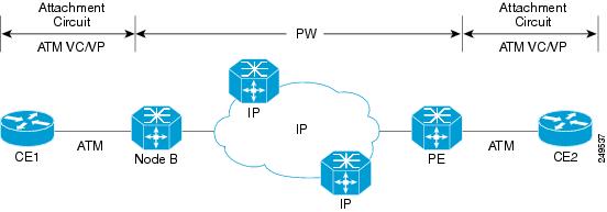
VCCV
provides a control channel that is associated with an ATM pseudowire to perform
operations and management functions over the pseudowire. BFD uses the VCCV
control channel to detect dataplane failures for pseudowires.
In Cisco
IOS Release 15.0(1)S the BFD control channel over VCCV Support for ATM
Pseudowire feature is supported for VCCV type-1 (without an IP/UDP header)
only.
The
following commands were introduced or modified by this feature:
bfd-template ,
debug
mpls
l2transport
vc
vccv ,
interval (BFD),
vccv ,
vccv
bfd
template ,
vccv
bfd
status
signaling .
|
|
BFD Echo
Mode
|
12.2(33)SRB
12.4(9)T
15.0(1)S
|
BFD echo
mode works with asynchronous BFD. Echo packets are sent by the forwarding
engine and forwarded back along the same path in order to perform
detection--the BFD session at the other end does not participate in the actual
forwarding of the echo packets. The echo function and the forwarding engine are
responsible for the detection process, therefore the number of BFD control
packets that are sent out between two BFD neighbors is reduced. And since the
forwarding engine is testing the forwarding path on the remote (neighbor)
system without involving the remote system, there is an opportunity to improve
the interpacket delay variance, thereby achieving quicker failure detection
times than when using BFD Version 0 with BFD control packets for the BFD
session.
|
|
BFD—BFD
Hardware Offload Support
|
15.1(2)S
15.1(1)SG
|
This
feature supports offloading BFD sessions to ES+ line cards on Cisco 7600 series
routers. The following command was introduced or modified:
show
bfd
neighbors
.
|
|
BFD IPv6
Encapsulation Support
|
Cisco IOS
XE Release 3.11S
|
This
feature extends IPv6 support for BFD.
The
following command was introduced or modified:
bfd interval
|
|
BFD Multihop
|
15.1(3)S
15.4(1)S
|
This feature
supports multihop BFD for IPv4 and IPv6 addresses.
In Cisco
IOS Release 15.4(1)S, support was added for the Cisco ASR 901S Series Routers.
The
following commands were introduced or modified:
authentication ,
bfd map ,
bfd-template ,
interval ,
show bfd
neighbors ,
show bfd neighbor
drops .
|
|
BFD—Static
Route Support
|
12.2(33)SRC
15.0(1)M
15.0(1)S
15.0(1)SY
15.1(2)S
15.1(1)SG
15.4(1)S
|
Unlike
dynamic routing protocols, such as OSPF and BGP, static routing has no method
of peer discovery. Therefore, when BFD is configured, the reachability of the
gateway is completely dependent on the state of the BFD session to the
specified neighbor. Unless the BFD session is up, the gateway for the static
route is considered unreachable, and therefore the affected routes will not be
installed in the appropriate RIB.
A single
BFD session can be used by an IPv4 static client to track the reachability of
next hops through a specific interface. A BFD group can be assigned for a set
of BFD-tracked static routes.
In Cisco
IOS Release 15.4(1)S, support was added for the Cisco ASR 901S Series Routers.
The
following commands were introduced or modified:
ip
route
static
bfd and
show
ip
static
route
bfd .
|
|
BFD
Support for IP Tunnel (GRE, with IP address)
|
15.1(1)SY
|
This
feature supports BFD forwarding on point-to-point IPv4, IPv6, and GRE tunnels.
The following commands were introduced or modified:
bfd
.
|
|
BFD
Support over Port Channel
|
15.1(1)SY
15.1(2)SY
|
This
feature supports configuring BFD timers on port channel interface.
The
following commands were introduced or modified:
bfd
.
|
|
BFD—VRF
Support
|
12.2(33)SRC
15.0(1)M
15.0(1)S
15.1(1)SY
|
The BFD
feature support is extended to be VPN Routing and Forwarding (VRF) aware to
provide fast detection of routing protocol failures between provider edge (PE)
and customer edge (CE) devices.
|
|
BFD—WAN
Interface Support
|
12.2(33)SRC
15.0(1)M
15.0(1)S
|
The BFD
feature is supported on nonbroadcast media interfaces including ATM, POS,
serial, and VLAN interfaces. BFD support also extends to ATM, FR, POS, and
serial subinterfaces.
The
bfd
interval command must be configured on the
interface to initiate BFD monitoring.
|
|
Bidirectional Forwarding Detection (standard implementation, Version 1)
|
12.0(31)S
12.0(32)S
12.2(33)SRB
12.2(33)SRC
12.2(18)SXE
12.2(33)SXH
12.4(9)T
12.4(11)T
12.4(15)T
15.0(1)S
15.4(1)S
|
This
document describes how to enable the Bidirectional Forwarding Detection (BFD)
protocol. BFD is a detection protocol designed to provide fast forwarding path
failure detection times for all media types, encapsulations, topologies, and
routing protocols. In addition to fast forwarding path failure detection, BFD
provides a consistent failure detection method for network administrators.
Because the network administrator can use BFD to detect forwarding path
failures at a uniform rate, rather than the variable rates for different
routing protocol hello mechanisms, network profiling and planning will be
easier, and reconvergence time will be consistent and predictable.
In
Release 12.0(31)S, support was added for the Cisco 12000 series Internet
router.
In
Release 12.0(32)S, support was added for the Cisco 10720 Internet router and IP
Services Engine (Engine 3) and Engine 5 shared port adapters (SPAs) and SPA
interface processors (SIPs) on the Cisco 12000 series Internet router.
In Cisco
IOS Release 15.4(1)S, support was added for the Cisco ASR 901S Series Routers.
|
|
HSRP
Support for BFD
|
12.2(33)SRC
12.4(11)T
12.4(15)T
|
In
Release 12.4(11)T, support for HSRP was added.
In
Release 12.4(15)T, BFD is supported on the Integrated Services Router (ISR)
family of Cisco routers, for example, the Cisco 3800 ISR series routers.
In
Release 12.2(33)SRC, the number of BFD sessions that can be created has been
increased, BFD support has been extended to ATM, FR, POS, and serial
subinterfaces, the BFD feature has been extended to be VRF-aware, BFD sessions
are placed in an “Admin Down” state during a planned switchover, and BFD
support has been extended to static routing.
|
|
IS-IS
Support for BFD over IPv4
|
12.0(31)S
12.2(18)SXE
12.2(33)SRA
12.4(4)T
15.0(1)S
15.4(1)S
|
BFD
support for OSPF can be configured globally on all interfaces or configured
selectively on one or more interfaces. When BFD support is configured with
IS-IS as a registered protocol with BFD, IS-IS receives forwarding path
detection failure messages from BFD.
In Cisco
IOS Release 15.4(1)S, support was added for the Cisco ASR 901S Series Routers.
|
|
OSPF
Support for BFD over IPv4
|
12.0(31)S
12.2(18)SXE
12.2(33)SRA
12.4(4)T
15.0(1)S
15.1(1)SG
|
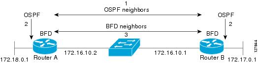
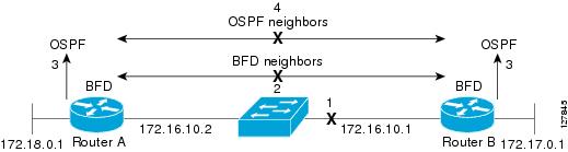
BFD
support for OSPF can be configured globally on all interfaces or configured
selectively on one or more interfaces. When BFD support is configured with OSPF
as a registered protocol with BFD, OSPF receives forwarding path detection
failure messages from BFD.
|
|
SSO—BFD
|
12.2(33)SRE
12.2(33)SXI2
12.2(33)XNE
15.0(1)S
15.1(1)SG
|
Network
deployments that use dual RP routers and switches have a graceful restart
mechanism to protect forwarding states across a switchover. This feature
enables BFD to maintain sessions in a up state across switchovers.
|
|
SSO—BFD
(Admin Down)
|
12.2(33)SRC
15.0(1)S
|
To
support SSO, BFD sessions are placed in an “Admin Down” state during a planned
switchover. The BFD configuration is synched from the active to standby
processor, and all BFD clients re-register with the BFD process on the standby
processor.
|
|
BFD Support on IPbasek9 Image for Cisco ISR G2 Modular
Routers.
|
15.6(3)M
|
Effective with Cisco IOS release 15.6(3)M, BFD is also
supported in the ipbasek9 image for Cisco ISR G2 modular routers. For example,
if EIGRP feature is part of the ipbasek9 image, the BFD for EIGRP feature will
be also part of the ipbasek9 image. When a feature is part of a software
package other than IP Base which supports BFD, the associated BFD feature will
be part of the equivalent software package.
|

 Feedback