Installing and Removing a Shared Port Adapter
This chapter describes how to install or remove SPAs on the Catalyst 6500 Series switch. This chapter contains the following sections:
•![]() SPA Cable-Management Brackets
SPA Cable-Management Brackets
Handling SPAs
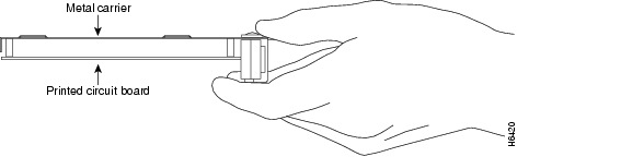
Each SPA circuit board is mounted to a metal carrier and is sensitive to electrostatic discharge (ESD) damage. Before you begin installation, read the "Preparing to Install a SIP or a Shared Port Adapter," chapter for a list of parts and tools required for installation.

When a subslot is not in use, a SPA blank filler plate must fill the empty subslot to allow the router or switch to conform to electromagnetic interference (EMI) emissions requirements and to allow proper airflow across the installed modules. If you plan to install a SPA in a subslot that is not in use, you must first remove the SPA blank filler plate.
Figure 6-1 Handling a SPA
SPA Installation and Removal
This section provides step-by-step instructions for installing and removing a SPA in a SIP.

Warning ![]() During this procedure, wear grounding wrist straps to avoid ESD damage to the card. Do not directly touch the backplane with your hand or any metal tool, or you could shock yourself. Statement 94
During this procedure, wear grounding wrist straps to avoid ESD damage to the card. Do not directly touch the backplane with your hand or any metal tool, or you could shock yourself. Statement 94
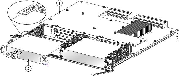
Figure 6-2 illustrates how to install and remove a SPA in a SIP.
Figure 6-2 SPA Installation and Removal
|
|
SIP |
|
SPA |
Installing a SPA in a SIP
To install a SPA in a SIP, refer to Figure 6-2 and do the following:
Step 1 ![]() To insert the SPA in the SIP, locate the guide rails inside the SIP that hold the SPA in place. They are at the top left and top right of the SPA slot and are recessed about an inch, as shown in Figure 6-2.
To insert the SPA in the SIP, locate the guide rails inside the SIP that hold the SPA in place. They are at the top left and top right of the SPA slot and are recessed about an inch, as shown in Figure 6-2.
Step 2 ![]() Carefully slide the SPA all the way in the SIP until the SPA is firmly seated in the SPA interface connector. When fully seated, the SPA might be slightly behind the SIP faceplate.
Carefully slide the SPA all the way in the SIP until the SPA is firmly seated in the SPA interface connector. When fully seated, the SPA might be slightly behind the SIP faceplate.
Step 3 ![]() After the SPA is properly seated, fasten the SPA in place with the captive installation screws.
After the SPA is properly seated, fasten the SPA in place with the captive installation screws.
Step 4 ![]() Tighten the screws to a torque of between 8.3 and 11 inch-pounds (94 to 124 N-cm). Do not overtighten.
Tighten the screws to a torque of between 8.3 and 11 inch-pounds (94 to 124 N-cm). Do not overtighten.
Removing a SPA from a SIP
To remove a SPA from a SIP, refer to Figure 6-2 and do the following:
Step 1 ![]() If attached, remove any cables from the SPA.
If attached, remove any cables from the SPA.
Step 2 ![]() To remove the SPA from the SIP, unfasten the captive installation screws on the SPA.
To remove the SPA from the SIP, unfasten the captive installation screws on the SPA.
Step 3 ![]() Grasp the handles of the SPA and pull the SPA from the SIP. (You have already disconnected the cables from the SPA when removing the SIP).
Grasp the handles of the SPA and pull the SPA from the SIP. (You have already disconnected the cables from the SPA when removing the SIP).
Online Insertion and Removal
Cisco 7600 series router SIPs and SPAs support online insertion and removal (OIR). SPAs can be inserted or removed independently from the SIP. OIR of a SIP with installed SPAs is also supported.
For more information about performing OIR, refer to the "Preparing for Online Removal of a SPA" section on page 5-4.
Optical Device Maintenance
Any contamination of the fiber connection can cause failure of the component or failure of the whole system. A particle that partially or completely blocks the core generates strong back reflections, which can cause instability in the laser system. Inspection, cleaning, and reinspection are critical steps to take before making fiber-optic connections.
Cleaning Optical Devices
See Inspection and Cleaning Procedures for Fiber-Optic Connections for information on cleaning optical devices.
Checking the Installation
This section describes the procedures you can use to verify the SIP and SPA installation, and includes information on the following topics:
•![]() Using show Commands to Verify SIP and SPA Status
Using show Commands to Verify SIP and SPA Status
•![]() Using show Commands to Display SPA Information
Using show Commands to Display SPA Information
Verifying the Installation
This section describes how to verify the SIP and SPA installation by observing the SIP LED states, SPA LED states, and the information displayed on the console terminal.
When the system has reinitialized all interfaces, the SIP STATUS LED should be green (on) and the SPA STATUS LEDs should be green (on). The port LEDs (C/A and A/L) may be green (on), depending on your connections and configuration. The console screen also displays a message as the system discovers each interface during its reinitialization.

Note ![]() A POS interface is used in the following examples for illustrative purposes.
A POS interface is used in the following examples for illustrative purposes.
The following sample display shows the events logged by the system as a SIP with a POS SPA was removed from module slot 4 in the router. In this example, interface 0 (interface 4/0/0) on the POS SPA was up and active when the SIP was removed from the router. Note that the system logs that the SIP card was removed from slot 4 and that interface 4/0/0 is changed to down.
Router#
00:06:17:%WS_ALARM-6-INFO:ASSERT CRITICAL slot 4 Active Card Removed OIR Alarm
00:06:17:%OIR-6-REMCARD:Card removed from slot 4, interfaces disabled
00:06:18:%LINEPROTO-5-UPDOWN:Line protocol on Interface pos4/0/0, changed state to down
When you reinsert the SIP with the installed POS SPA, the system automatically brings up the interface that was changed to down when the SIP was removed.
Router#
00:07:29:%OIR-6-INSCARD:Card inserted in slot 4, interfaces administratively shut down
00:07:32:%WS_ALARM-6-INFO:CLEAR CRITICAL slot 4 Active Card Removed OIR Alarm
00:07:35:%LINK-3-UPDOWN:Interface pos4/0/0, changed state to up
00:07:36:%LINEPROTO-5-UPDOWN:Line protocol on Interface pos4/0/0, changed state to up
Use the following procedure to verify that a SIP and SPA are installed correctly:
Step 1 ![]() Observe the console display messages and verify that the system discovers the SIP, while the system reinitializes each interface, as follows:
Observe the console display messages and verify that the system discovers the SIP, while the system reinitializes each interface, as follows:
•![]() As a SIP is initialized, the STATUS LED will first be amber, indicating that power is on, but the SIP is being configured. When the SIP is active, the STATUS LED will illuminate green.
As a SIP is initialized, the STATUS LED will first be amber, indicating that power is on, but the SIP is being configured. When the SIP is active, the STATUS LED will illuminate green.
•![]() SPAs will follow the same sequence once the SIP has completed its initialization. The SPA STATUS LEDs will illuminate amber, turning to green when the SPAs become active.
SPAs will follow the same sequence once the SIP has completed its initialization. The SPA STATUS LEDs will illuminate amber, turning to green when the SPAs become active.
•![]() When the SIP and SPA STATUS LEDs are green, all associated interfaces are configurable.
When the SIP and SPA STATUS LEDs are green, all associated interfaces are configurable.
Refer to the Catalyst 6500 Series Switch SIP, SSC, and SPA Software Configuration Guide for configuration instructions.
•![]() If a SIP or SPA is replaced with a module of the same type (as in an OIR or hardware swap), the previous configuration will be reinstated when the SIP or SPA becomes active.
If a SIP or SPA is replaced with a module of the same type (as in an OIR or hardware swap), the previous configuration will be reinstated when the SIP or SPA becomes active.
•![]() If a SIP or SPA has not been previously installed in the same slot or subslot, then the configuration for all associated interfaces will be empty.
If a SIP or SPA has not been previously installed in the same slot or subslot, then the configuration for all associated interfaces will be empty.
Note ![]() New interfaces are not available until you configure them.
New interfaces are not available until you configure them.
Step 2 ![]() If the SIPs and SPAs have not become active within three minutes, refer to the system console messages as follows:
If the SIPs and SPAs have not become active within three minutes, refer to the system console messages as follows:
•![]() If a SIP or SPA is undergoing an FPD upgrade, then console messages will indicate that the FPD process has been initiated. The upgrade process might take several minutes. Use the show upgrade fpd progress command to obtain information about the FPD process. SIPs or SPAs that undergo an FPD upgrade will automatically be rebooted. Return to Step 1.
If a SIP or SPA is undergoing an FPD upgrade, then console messages will indicate that the FPD process has been initiated. The upgrade process might take several minutes. Use the show upgrade fpd progress command to obtain information about the FPD process. SIPs or SPAs that undergo an FPD upgrade will automatically be rebooted. Return to Step 1.
•![]() If there is no indication that an FPD upgrade is under way, see Chapter 7, "Troubleshooting the Installation."
If there is no indication that an FPD upgrade is under way, see Chapter 7, "Troubleshooting the Installation."
Using show Commands to Verify SIP and SPA Status
The following procedure uses show commands to verify that the new SPAs are configured and operating correctly.
Step 1 ![]() Use the show running-config command to display the system configuration. Verify that the configuration includes the new SPA interfaces.
Use the show running-config command to display the system configuration. Verify that the configuration includes the new SPA interfaces.
Step 2 ![]() Display all of the current SPAs and a summary of their status using the show hw-module subslot all oir command.
Display all of the current SPAs and a summary of their status using the show hw-module subslot all oir command.
Step 3 ![]() Display information about the installed SIPs using the show diag command.
Display information about the installed SIPs using the show diag command.
Step 4 ![]() Use the show hw-module subslot all fpd command to verify the FPD version information of the SPAs installed in the system.
Use the show hw-module subslot all fpd command to verify the FPD version information of the SPAs installed in the system.
Note ![]() If a SPA does not meet the minimum FPD version required, it will be updated automatically. If the update fails, the failing SPA will be powered down and an error message will be reported on the system console.
If a SPA does not meet the minimum FPD version required, it will be updated automatically. If the update fails, the failing SPA will be powered down and an error message will be reported on the system console.
For more information about FPD upgrades, refer to the "Upgrading Field-Programmable Devices" chapter of the Catalyst 6500 Series Switch SIP, SSC, and SPA Software Configuration Guide.
Step 5 ![]() Use the show version command to obtain a few details on the installed SIPs and interfaces available.
Use the show version command to obtain a few details on the installed SIPs and interfaces available.
Using show Commands to Display SPA Information
Table 6-1 describes the show commands you can use to display SPA information.
SPA Blank Filler Plates
SPA blank filler plates are available to fill an unused SPA subslot.
When a SPA subslot is not in use, a SPA blank filler plate must be installed in the empty subslot to allow the router or switch to conform to electromagnetic interference (EMI) emissions requirements and to allow proper airflow across the SPAs. If you plan to install a new SPA in a subslot that is not in use, you must first remove the SPA blank filler plate.
SPA Cable-Management Brackets
SPAs are shipped with an accessory kit that includes cable-management brackets. Figure 6-3 shows cable-management brackets installed in a SPA, as well as cable routing.
Figure 6-3 SPA Cable-Management Brackets

To install cable-management brackets on a SPA, perform the following steps:
Step 1 ![]() Screw the two pull assemblies into both sides of the SPA.
Screw the two pull assemblies into both sides of the SPA.
Step 2 ![]() Insert the cable-management clip into the slot.
Insert the cable-management clip into the slot.
Step 3 ![]() To remove the cable-management clip, depress the button on the clip and pull it out.
To remove the cable-management clip, depress the button on the clip and pull it out.
Note ![]() Blank filler plugs are provided if no cable-management clips are installed.
Blank filler plugs are provided if no cable-management clips are installed.
 Feedback