Overview
The Catalyst 6500 series Content Switching Module (CSM) provides high-performance server load balancing (SLB) among groups of servers, firewalls, caches, VPN termination devices, and other network devices, based on Layer 3 as well as Layer 4 through Layer 7 packet information. Server farms are groups of load balanced devices.
Server farms that are represented as virtual servers can improve scalability and availability of services for your network. You can add new servers and remove failed or existing servers at any time without affecting the virtual server's availability.
Clients connect to the CSM directing their requests to the virtual IP (VIP) address of the virtual server. When a client initiates a connection to the virtual server, the CSM chooses a real server (a physical device that is assigned to a server farm) for the connection based on configured load-balancing algorithms and policies (access rules). Policies manage traffic by defining where to send client connections.
Sticky connections limit traffic to individual servers by allowing multiple connections from the same client to stick to the same real server using source IP addresses, source IP subnets, cookies, and the secure socket layer (SSL) or by redirecting these connections using Hypertext Transfer Protocol (HTTP) redirect messages.

These sections describe the CSM:
Features
The CSM provides these enhanced features:
•![]() More than one CSM can run in a Catalyst 6500 series switch chassis, and CSMs can run concurrently with Cisco IOS server load balancing (SLB).
More than one CSM can run in a Catalyst 6500 series switch chassis, and CSMs can run concurrently with Cisco IOS server load balancing (SLB).
•![]() CSM fault-tolerance support allows two CSM modules (in the same or in different chassis) to be configured in the active and standby modes.
CSM fault-tolerance support allows two CSM modules (in the same or in different chassis) to be configured in the active and standby modes.
•![]() The sticky database and connection table also can be replicated from active to standby to minimize any service disruption.
The sticky database and connection table also can be replicated from active to standby to minimize any service disruption.
•![]() CSM firewall load balancing allows you to scale firewall protection. Multiple firewall farms and DMZs are supported.
CSM firewall load balancing allows you to scale firewall protection. Multiple firewall farms and DMZs are supported.
•![]() A configurable pending-connection timeout feature is available. Pending-connection timeout sets the response time for terminating connections if a switch is flooded with traffic. This feature is used to prevent denial of service (DOS) attacks. Pending connections are configurable on a per virtual server basis.
A configurable pending-connection timeout feature is available. Pending-connection timeout sets the response time for terminating connections if a switch is flooded with traffic. This feature is used to prevent denial of service (DOS) attacks. Pending connections are configurable on a per virtual server basis.
•![]() The CSM supports 255 VLANs (including the client VLANs, server VLANs and one fault tolerant VLAN used for redundant pairs of CSMs).
The CSM supports 255 VLANs (including the client VLANs, server VLANs and one fault tolerant VLAN used for redundant pairs of CSMs).
•![]() The minimum time between health probes has been reduced to 2 seconds, starting from release 2.1(1).
The minimum time between health probes has been reduced to 2 seconds, starting from release 2.1(1).
•![]() Sample scripts are available for reference to support the TCL (Toolkit Command Language) feature. The filename is: c6slb-script.3-1-1a.tcl. This file is located with the CSM Release 3.1(1a) software image at this URL:
Sample scripts are available for reference to support the TCL (Toolkit Command Language) feature. The filename is: c6slb-script.3-1-1a.tcl. This file is located with the CSM Release 3.1(1a) software image at this URL:
Table 1-1 lists the new CSM features in this release.
Table 1-2 lists the CSM features available in this release and previous releases.
Front Panel Description
Figure 1-1 shows the CSM front panel.
Figure 1-1 Content Switching Module Front Panel
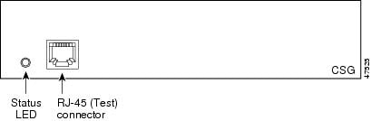

Note ![]() The RJ-45 connector is covered by a removable plate.
The RJ-45 connector is covered by a removable plate.
Status LED
When the CSM powers up, it initializes various hardware components and communicates with the supervisor engine. The Status LED indicates the supervisor engine operations and the initialization results. During the normal initialization sequence, the status LED changes from off to red, orange, and green.
Note ![]() For more information on the supervisor engine LEDs, refer to the Catalyst 6500 Series Module Installation Guide.
For more information on the supervisor engine LEDs, refer to the Catalyst 6500 Series Module Installation Guide.
Table 1-3 describes the Status LED operation.
|
|
|
|---|---|
Off |
• • • – – |
Red |
• • |
Orange |
• • • • |
Green |
• |
Green to orange |
• |
1 Enter the show environment temperature mod command to display the temperature of each of four sensors on the CSM. 2 CLI = command-line interface. |
RJ-45 Connector
The RJ-45 connector, which is covered by a removable plate, is used to connect a management station device or a test device. This connector is used by field engineers to perform testing and to obtain dump information.
Operation Mode
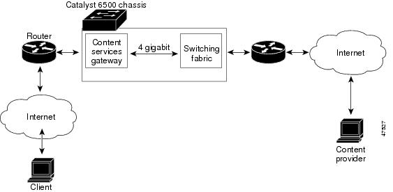
Clients and servers communicate through the CSM using Layer 2 and Layer 3 technology in a specific VLAN configuration. (See Figure 1-2.) In a simple SLB deployment, clients connect to the client-side VLAN and servers connect to the server-side VLAN. Servers and clients can exist on different subnets. Servers can also be located one or more Layer 3 hops away and connect to the CSM through routers.
A client sends a request to one of the module's VIP addresses. The CSM forwards this request to a server that can respond to the request. The server then forwards the response to the CSM, and the CSM forwards the response to the client.
When the client-side and server-side VLANs are on the same subnets, you can configure the CSM in single subnet (bridge) mode. For more information, see the "Configuring the Single Subnet (Bridge) Mode" section.
When the client-side and server-side VLANs are on different subnets, you can configure the CSM to operate in a secure (router) mode. For more information, see the "Configuring the Secure (Router) Mode" section.
You can set up a fault-tolerant configuration in either the secure (router) or single subnet (bridged) mode using redundant CSMs. For more information, see the "Configuring Fault Tolerance" section.
Using multiple VLANs, single subnet (bridge) mode and secure (router) mode can coexist in the same CSM.
Figure 1-2 Content Switching Module and Servers
Traffic Flow
This section describes how the traffic flows between the client and server in a CSM environment. (See Figure 1-3.)
Figure 1-3 Traffic Flow between Client and Server
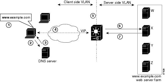
Note ![]() The numbers in Figure 1-3 correspond to the steps in the following procedure.
The numbers in Figure 1-3 correspond to the steps in the following procedure.
When you enter a request for information by entering a URL, the traffic flows as follows:
1. ![]() You enter a URL. (Figure 1-3 shows www.example.com as an example.)
You enter a URL. (Figure 1-3 shows www.example.com as an example.)
2. ![]() The client contacts a DNS server to locate the IP address associated with the URL.
The client contacts a DNS server to locate the IP address associated with the URL.
3. ![]() The DNS server sends the IP address of the virtual IP (VIP) to the client.
The DNS server sends the IP address of the virtual IP (VIP) to the client.
4. ![]() The client uses the IP address (CSM VIP) to send the HTTP request to the CSM.
The client uses the IP address (CSM VIP) to send the HTTP request to the CSM.
5. ![]() The CSM receives the request with the URL, makes a load-balancing decision, and selects a server.
The CSM receives the request with the URL, makes a load-balancing decision, and selects a server.
For example, in Figure 1-3, the CSM selects a server (X server) from the www.example.com server pool, replacing its own VIP address with the address of the X server (directed mode), and forwards the traffic to the X server. If the NAT server option is disabled, the VIP address remains unchanged (dispatch mode).
6. ![]() The CSM performs Network Address Translation (NAT) and eventually TCP sequence numbers translation.
The CSM performs Network Address Translation (NAT) and eventually TCP sequence numbers translation.
 Feedback