Catalyst 6500 Series Switch Content Switching Module (CSM) Installation and Configuration Note Software Release 3.1
Bias-Free Language
The documentation set for this product strives to use bias-free language. For the purposes of this documentation set, bias-free is defined as language that does not imply discrimination based on age, disability, gender, racial identity, ethnic identity, sexual orientation, socioeconomic status, and intersectionality. Exceptions may be present in the documentation due to language that is hardcoded in the user interfaces of the product software, language used based on RFP documentation, or language that is used by a referenced third-party product. Learn more about how Cisco is using Inclusive Language.
- Updated:
- March 18, 2015
Chapter: Installing the Hardware
Installing the Hardware
This chapter describes how to install the CSM into the Catalyst 6500 series switch and contains these sections:
System Requirements
Before you install the CSM into the Catalyst 6500 series switch, make sure that the switch meets the hardware and software requirements listed in this section.

Memory Requirements
The CSM memory is not configurable.
Supported Hardware
Before you can use the CSM, you must have a Supervisor Engine 1A with an MSFC, a Policy Feature Card (PFC) or a Supervisor Engine 2 with an MSFC, and any module that has ports to connect server and client networks.
Table 2-1 lists the supported hardware and software for the CSM:
Power Supply
You can place the CSM in any slot in the Catalyst 6500 series chassis except for the slots occupied by the supervisor engine and the standby supervisor engine. The CSM operates on power supplied by the chassis.
Software Requirements
Table 2-2 lists the software versions for the CSM:
Software Compatibility
Beginning with software release 2.1(1), backward compatibility is not allowed.
If the CSM software image version you are using is more recent than the Cisco IOS software specified for that release in Table 2-2, you will not have all the CSM features available to you. For example, if you are running CSM software release 3.1(1a) with Cisco IOS software release 12.1(11b)E, the Cisco IOS software will not have the new CLI commands that support the CSM 3.1(1a) features.
If the CSM software image version you are using is older than the Cisco IOS software specified for that release in Table 2-2, the older CSM application software will not understand the newer IOS commands. The CSM software will still run, however the new IOS commands will have no effect.
Environmental Requirements
Table 2-3 lists the environmental requirements for the CSM:
Installing the CSM
The following sections describe how to install the CSM:
•![]() Installing and Removing the Module
Installing and Removing the Module
Preparing to Install the CSM
Before installing the CSM, make sure that the following items are available:
•![]() Catalyst 6500 series switch chassis
Catalyst 6500 series switch chassis
•![]() Management station that is available through a Telnet or a console connection to perform configuration tasks
Management station that is available through a Telnet or a console connection to perform configuration tasks
Required Tools
These tools are required to install the module in the Catalyst 6500 series switches:
•![]() Flat-blade screwdriver
Flat-blade screwdriver
•![]() Phillips-head screwdriver
Phillips-head screwdriver
•![]() Wrist strap or other grounding device
Wrist strap or other grounding device
•![]() Antistatic mat or antistatic foam
Antistatic mat or antistatic foam
Whenever you handle the module, always use a wrist strap or other grounding device to prevent electrostatic discharge (ESD).
Installing and Removing the Module

Warning ![]() During this procedure, wear grounding wrist straps to avoid ESD damage to the card. Do not directly touch the backplane with your hand or any metal tool, or you could shock yourself.
During this procedure, wear grounding wrist straps to avoid ESD damage to the card. Do not directly touch the backplane with your hand or any metal tool, or you could shock yourself.
All Catalyst 6500 series switches support hot swapping, which allows you to install, remove, replace, and rearrange modules without turning off the system power. For more information on removing the module from a switch, see the "Removing the Module" section.
When the system detects that a module has been installed or removed, the system automatically runs diagnostic and discovery routines, acknowledges the presence or absence of the module, and resumes system operation.
This section describes how to install and verify the operation of the Firewall Services Module in the Catalyst 6500 series switches and contains the following sections:
Slot Assignments
The Catalyst 6006 and 6506 switch chassis have six slots, the Catalyst 6009 and 6509 switch chassis have nine slots, and the Catalyst 6513 switch chassis has thirteen slots.

Note ![]() The Catalyst 6509-NEB switch has vertical slots, which are numbered 1 to 9 from right to left. Install the modules with the component side facing to the right.
The Catalyst 6509-NEB switch has vertical slots, which are numbered 1 to 9 from right to left. Install the modules with the component side facing to the right.
•![]() Slot 1 is reserved for the supervisor engine.
Slot 1 is reserved for the supervisor engine.
•![]() Slot 2 can be used for a redundant supervisor engine in case the supervisor engine in slot 1 fails.
Slot 2 can be used for a redundant supervisor engine in case the supervisor engine in slot 1 fails.
•![]() If a redundant supervisor engine is not required, slots 2 through 6 on the 6-slot chassis, slots 2 through 9 on the 9-slot chassis, and slots 2 through 13 on the 13-slot chassis are available for switching modules, such as the Firewall Services Module.
If a redundant supervisor engine is not required, slots 2 through 6 on the 6-slot chassis, slots 2 through 9 on the 9-slot chassis, and slots 2 through 13 on the 13-slot chassis are available for switching modules, such as the Firewall Services Module.
•![]() The empty slots require filler plates, which are blank switching-module carriers that maintain consistent airflow through the switch chassis.
The empty slots require filler plates, which are blank switching-module carriers that maintain consistent airflow through the switch chassis.
Removing the Module
This section describes how to remove an existing module from a Catalyst 6500 series switch chassis slot.
Warning ![]() During this procedure, wear grounding wrist straps to avoid ESD damage to the card. Do not directly touch the backplane with your hand or any metal tool, or you could shock yourself.
During this procedure, wear grounding wrist straps to avoid ESD damage to the card. Do not directly touch the backplane with your hand or any metal tool, or you could shock yourself.
Warning ![]() Before you install, operate, or service the system, read the Site Preparation and Safety Guide. This guide contains important safety information you should know before working with the system.
Before you install, operate, or service the system, read the Site Preparation and Safety Guide. This guide contains important safety information you should know before working with the system.
Warning ![]() Invisible laser radiation may be emitted from disconnected fibers or connectors. Do not stare into beams or view directly with optical instruments.
Invisible laser radiation may be emitted from disconnected fibers or connectors. Do not stare into beams or view directly with optical instruments.
To remove a supervisor engine or module from the chassis, perform these steps:
Step 1 ![]() Disconnect any network interface cables attached to the supervisor engine or module.
Disconnect any network interface cables attached to the supervisor engine or module.
Step 2 ![]() Verify that the captive installation screws on all of the modules in the chassis are tight.
Verify that the captive installation screws on all of the modules in the chassis are tight.
This step assures that the space created by the removed module is maintained.
Note ![]() If the captive installation screws are loose, the electromagnetic interference (EMI) gaskets on the installed modules will push the modules toward the open slot, reducing the opening size and making it difficult to install the replacement module.
If the captive installation screws are loose, the electromagnetic interference (EMI) gaskets on the installed modules will push the modules toward the open slot, reducing the opening size and making it difficult to install the replacement module.
Step 3 ![]() Loosen the two captive installation screws on the supervisor engine or module.
Loosen the two captive installation screws on the supervisor engine or module.
Step 4 ![]() Depending on the orientation of the slots in the chassis (horizontal or vertical), perform one of the following set of substeps:
Depending on the orientation of the slots in the chassis (horizontal or vertical), perform one of the following set of substeps:
Horizontal slots
a. ![]() Place your thumbs on the left and right ejector levers, and simultaneously rotate the levers outward to unseat the module from the backplane connector.
Place your thumbs on the left and right ejector levers, and simultaneously rotate the levers outward to unseat the module from the backplane connector.
b. ![]() Grasp the front edge of the module, and slide the module part of the way out of the slot. Place your other hand under the module to support the weight of the module. Do not touch the module circuitry.
Grasp the front edge of the module, and slide the module part of the way out of the slot. Place your other hand under the module to support the weight of the module. Do not touch the module circuitry.
Vertical slots
a. ![]() Place your thumbs on the ejector levers located at the top and bottom of the module, and simultaneously rotate the levers outward to unseat the module from the backplane connector.
Place your thumbs on the ejector levers located at the top and bottom of the module, and simultaneously rotate the levers outward to unseat the module from the backplane connector.
b. ![]() Grasp the edges of the module, and slide the module straight out of the slot. Do not touch the module circuitry.
Grasp the edges of the module, and slide the module straight out of the slot. Do not touch the module circuitry.
Step 5 ![]() Place the module on an antistatic mat or antistatic foam, or immediately reinstall it in another slot.
Place the module on an antistatic mat or antistatic foam, or immediately reinstall it in another slot.
Step 6 ![]() If the slot from which you removed the module is to remain empty, install a module filler plate to keep dust out of the chassis and to maintain proper airflow through the chassis.
If the slot from which you removed the module is to remain empty, install a module filler plate to keep dust out of the chassis and to maintain proper airflow through the chassis.
Warning ![]() Blank faceplates (filler panels) serve three important functions: they prevent exposure to hazardous voltages and currents inside the chassis; they contain electromagnetic interference (EMI) that might disrupt other equipment; and they direct the flow of cooling air through the chassis. Do not operate the system unless all cards and faceplates are in place.
Blank faceplates (filler panels) serve three important functions: they prevent exposure to hazardous voltages and currents inside the chassis; they contain electromagnetic interference (EMI) that might disrupt other equipment; and they direct the flow of cooling air through the chassis. Do not operate the system unless all cards and faceplates are in place.
Installing a Module
This section describes how to install modules in the Catalyst 6500 series switches.
Warning ![]() During this procedure, wear grounding wrist straps to avoid ESD damage to the card. Do not directly touch the backplane with your hand or any metal tool, or you could shock yourself.
During this procedure, wear grounding wrist straps to avoid ESD damage to the card. Do not directly touch the backplane with your hand or any metal tool, or you could shock yourself.
Warning ![]() Invisible laser radiation may be emitted from disconnected fibers or connectors. Do not stare into beams or view directly with optical instruments.
Invisible laser radiation may be emitted from disconnected fibers or connectors. Do not stare into beams or view directly with optical instruments.
Warning ![]() Before you install, operate, or service the system, read the Site Preparation and Safety Guide. This guide contains important safety information you should know before working with the system.
Before you install, operate, or service the system, read the Site Preparation and Safety Guide. This guide contains important safety information you should know before working with the system.
To install a supervisor engine or module in the chassis, perform these steps:
Step 1 ![]() Choose a slot for the supervisor engine or module.
Choose a slot for the supervisor engine or module.
Step 2 ![]() Verify that there is enough clearance to accommodate any interface equipment that you will connect directly to the supervisor engine or module ports. If possible, place modules between empty slots that contain only module filler plates.
Verify that there is enough clearance to accommodate any interface equipment that you will connect directly to the supervisor engine or module ports. If possible, place modules between empty slots that contain only module filler plates.
Step 3 ![]() Verify that the captive installation screws are tightened on all modules installed in the chassis.
Verify that the captive installation screws are tightened on all modules installed in the chassis.
This action ensures that the EMI gaskets on all modules are fully compressed in order to maximize the opening space for the replacement module.
Note ![]() If the captive installation screws are loose, the EMI gaskets on the installed modules will push adjacent modules toward the open slot, reducing the opening size and making it difficult to install the replacement module.
If the captive installation screws are loose, the EMI gaskets on the installed modules will push adjacent modules toward the open slot, reducing the opening size and making it difficult to install the replacement module.
Step 4 ![]() Remove the module filler plate by removing the two Phillips pan-head screws from the filler plate. (To remove a module, refer to "Removing the Module" section.)
Remove the module filler plate by removing the two Phillips pan-head screws from the filler plate. (To remove a module, refer to "Removing the Module" section.)
Step 5 ![]() Fully open both ejector levers on the new or replacement module. (See Figure 2-1.)
Fully open both ejector levers on the new or replacement module. (See Figure 2-1.)
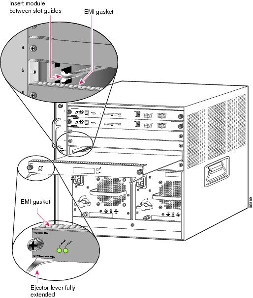
Figure 2-1 Positioning the Module in a Horizontal Slot Chassis
Step 6 ![]() Depending on the orientation of the slots in the chassis (horizontal or vertical), perform one of the following sets of substeps:
Depending on the orientation of the slots in the chassis (horizontal or vertical), perform one of the following sets of substeps:
Horizontal slots
a. ![]() Position the supervisor engine or module in the slot. Make sure that you align the sides of the module carrier with the slot guides on each side of the slot. (See Figure 2-1.)
Position the supervisor engine or module in the slot. Make sure that you align the sides of the module carrier with the slot guides on each side of the slot. (See Figure 2-1.)
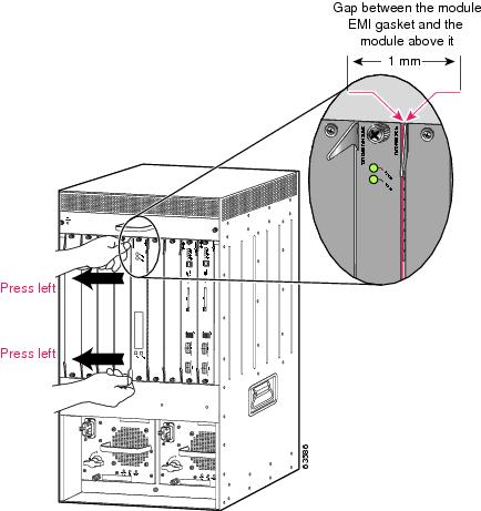
b. ![]() Carefully slide the supervisor engine or module into the slot until the EMI gasket along the top edge of the module makes contact with the module in the slot above it and both ejector levers have closed to approximately 45 degrees with respect to the module faceplate. (See Figure 2-2.)
Carefully slide the supervisor engine or module into the slot until the EMI gasket along the top edge of the module makes contact with the module in the slot above it and both ejector levers have closed to approximately 45 degrees with respect to the module faceplate. (See Figure 2-2.)
Figure 2-2 Clearing the EMI Gasket in a Horizontal Slot Chassis
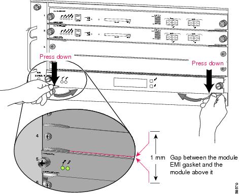
c. ![]() Using the thumb and forefinger of each hand, grasp the two ejector levers and press down to create a small (0.040 inch [1 mm]) gap between the module's EMI gasket and the module above it. (See Figure 2-2.)
Using the thumb and forefinger of each hand, grasp the two ejector levers and press down to create a small (0.040 inch [1 mm]) gap between the module's EMI gasket and the module above it. (See Figure 2-2.)
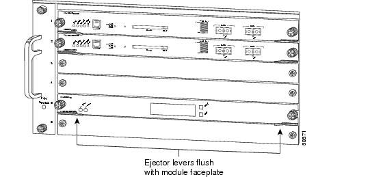
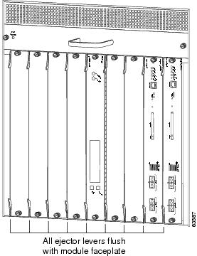
d. ![]() While pressing down, simultaneously close the left and right ejector levers to fully seat the supervisor engine or module in the backplane connector. The ejector levers are fully closed when they are flush with the module faceplate. (See Figure 2-3.)
While pressing down, simultaneously close the left and right ejector levers to fully seat the supervisor engine or module in the backplane connector. The ejector levers are fully closed when they are flush with the module faceplate. (See Figure 2-3.)
Figure 2-3 Ejector Lever Closure in a Horizontal Slot Chassis
Note ![]() Failure to fully seat the module in the backplane connector can result in error messages.
Failure to fully seat the module in the backplane connector can result in error messages.
e. ![]() Tighten the two captive installation screws on the supervisor engine or module.
Tighten the two captive installation screws on the supervisor engine or module.
Note ![]() Make sure the ejector levers are fully closed before tightening the captive installation screws.
Make sure the ejector levers are fully closed before tightening the captive installation screws.
Vertical slots
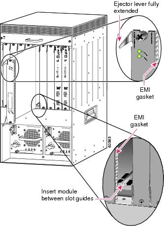
a. ![]() Position the supervisor engine or switching module in the slot. (See Figure 2-4.) Make sure that you align the sides of the switching-module carrier with the slot guides on the top and bottom of the slot.
Position the supervisor engine or switching module in the slot. (See Figure 2-4.) Make sure that you align the sides of the switching-module carrier with the slot guides on the top and bottom of the slot.
Figure 2-4 Positioning the Module in a Vertical Slot Chassis
b. ![]() Carefully slide the supervisor engine or module into the slot until the EMI gasket along the right edge of the module makes contact with the module in the slot adjacent to it and both ejector levers have closed to approximately 45 degrees with respect to the module faceplate. (See Figure 2-5.)
Carefully slide the supervisor engine or module into the slot until the EMI gasket along the right edge of the module makes contact with the module in the slot adjacent to it and both ejector levers have closed to approximately 45 degrees with respect to the module faceplate. (See Figure 2-5.)
c. ![]() Using the thumb and forefinger of each hand, grasp the two ejector levers and exert a slight pressure to the left, deflecting the module approximately 0.040 inches (1 mm) to create a small gap between the module's EMI gasket and the module adjacent to it. (See Figure 2-5.)
Using the thumb and forefinger of each hand, grasp the two ejector levers and exert a slight pressure to the left, deflecting the module approximately 0.040 inches (1 mm) to create a small gap between the module's EMI gasket and the module adjacent to it. (See Figure 2-5.)
Figure 2-5 Clearing the EMI Gasket in a Vertical Slot Chassis
d. ![]() While pressing on the ejector levers, simultaneously close them to fully seat the supervisor engine or module in the backplane connector. The ejector levers are fully closed when they are flush with the module faceplate. (See Figure 2-6.)
While pressing on the ejector levers, simultaneously close them to fully seat the supervisor engine or module in the backplane connector. The ejector levers are fully closed when they are flush with the module faceplate. (See Figure 2-6.)
Figure 2-6 Ejector Lever Closure in a Vertical Slot Chassis
e. ![]() Tighten the two captive installation screws on the module.
Tighten the two captive installation screws on the module.
Note ![]() Make sure the ejector levers are fully closed before tightening the captive installation screws.
Make sure the ejector levers are fully closed before tightening the captive installation screws.
This completes the CSM installation procedure.
Verifying the Installation
When you install the CSM into the Catalyst 6500 series switch, the module goes through a boot sequence that requires no intervention. At the successful conclusion of the boot sequence, the green Status LED will light and remain on. If the Status LED does not show green, or if it shows a different color, refer to Table 1-3 to determine the module's status.
 Feedback