Cisco UCS C240 M5 with Scality RING 8
Available Languages
Bias-Free Language
The documentation set for this product strives to use bias-free language. For the purposes of this documentation set, bias-free is defined as language that does not imply discrimination based on age, disability, gender, racial identity, ethnic identity, sexual orientation, socioeconomic status, and intersectionality. Exceptions may be present in the documentation due to language that is hardcoded in the user interfaces of the product software, language used based on RFP documentation, or language that is used by a referenced third-party product. Learn more about how Cisco is using Inclusive Language.
- US/Canada 800-553-2447
- Worldwide Support Phone Numbers
- All Tools
 Feedback
 Feedback

Cisco UCS C240 M5 with Scality RING 8
Design and Deployment Guide for Scality RING 8 + Scality NAS Archiver on Cisco UCS C240 M5 with Cisco Intersight and Terraform
Published: October 2020
In partnership with:
![]()
About the Cisco Validated Design Program
The Cisco Validated Design (CVD) program consists of systems and solutions designed, tested, and documented to facilitate faster, more reliable, and more predictable customer deployments. For more information, go to:
http://www.cisco.com/go/designzone.
ALL DESIGNS, SPECIFICATIONS, STATEMENTS, INFORMATION, AND RECOMMENDATIONS (COLLECTIVELY, "DESIGNS") IN THIS MANUAL ARE PRESENTED "AS IS," WITH ALL FAULTS. CISCO AND ITS SUPPLIERS DISCLAIM ALL WARRANTIES, INCLUDING, WITHOUT LIMITATION, THE WARRANTY OF MERCHANTABILITY, FITNESS FOR A PARTICULAR PURPOSE AND NONINFRINGEMENT OR ARISING FROM A COURSE OF DEALING, USAGE, OR TRADE PRACTICE. IN NO EVENT SHALL CISCO OR ITS SUPPLIERS BE LIABLE FOR ANY INDIRECT, SPECIAL, CONSEQUENTIAL, OR INCIDENTAL DAMAGES, INCLUDING, WITHOUT LIMITATION, LOST PROFITS OR LOSS OR DAMAGE TO DATA ARISING OUT OF THE USE OR INABILITY TO USE THE DESIGNS, EVEN IF CISCO OR ITS SUPPLIERS HAVE BEEN ADVISED OF THE POSSIBILITY OF SUCH DAMAGES.
THE DESIGNS ARE SUBJECT TO CHANGE WITHOUT NOTICE. USERS ARE SOLELY RESPONSIBLE FOR THEIR APPLICATION OF THE DESIGNS. THE DESIGNS DO NOT CONSTITUTE THE TECHNICAL OR OTHER PROFESSIONAL ADVICE OF CISCO, ITS SUPPLIERS OR PARTNERS. USERS SHOULD CONSULT THEIR OWN TECHNICAL ADVISORS BEFORE IMPLEMENTING THE DESIGNS. RESULTS MAY VARY DEPENDING ON FACTORS NOT TESTED BY CISCO.
CCDE, CCENT, Cisco Eos, Cisco Lumin, Cisco Nexus, Cisco StadiumVision, Cisco TelePresence, Cisco WebEx, the Cisco logo, DCE, and Welcome to the Human Network are trademarks; Changing the Way We Work, Live, Play, and Learn and Cisco Store are service marks; and Access Registrar, Aironet, AsyncOS, Bringing the Meeting To You, Catalyst, CCDA, CCDP, CCIE, CCIP, CCNA, CCNP, CCSP, CCVP, Cisco, the Cisco Certified Internetwork Expert logo, Cisco IOS, Cisco Press, Cisco Systems, Cisco Systems Capital, the Cisco Systems logo, Cisco Unified Computing System (Cisco UCS), Cisco UCS B-Series Blade Servers, Cisco UCS C-Series Rack Servers, Cisco UCS S-Series Storage Servers, Cisco UCS Manager, Cisco UCS Management Software, Cisco Unified Fabric, Cisco Application Centric Infrastructure, Cisco Nexus 9000 Series, Cisco Nexus 7000 Series. Cisco Prime Data Center Network Manager, Cisco NX-OS Software, Cisco MDS Series, Cisco Unity, Collaboration Without Limitation, EtherFast, EtherSwitch, Event Center, Fast Step, Follow Me Browsing, FormShare, GigaDrive, HomeLink, Internet Quotient, IOS, iPhone, iQuick Study, LightStream, Linksys, MediaTone, MeetingPlace, MeetingPlace Chime Sound, MGX, Networkers, Networking Academy, Network Registrar, PCNow, PIX, PowerPanels, ProConnect, ScriptShare, SenderBase, SMARTnet, Spectrum Expert, StackWise, The Fastest Way to Increase Your Internet Quotient, TransPath, WebEx, and the WebEx logo are registered trademarks of Cisco Systems, Inc. and/or its affiliates in the United States and certain other countries. Lisa.
All other trademarks mentioned in this document or website are the property of their respective owners. The use of the word partner does not imply a partnership relationship between Cisco and any other company. (0809R)
© 2020 Cisco Systems, Inc. All rights reserved.
Contents
Deployment Hardware and Software
Installation of Cisco Intersight
Create a Terraform Configuration Environment for Cisco Intersight
Configure Scality RING Infrastructure with Terraform
Prepare Virtual Environment for Scality RING Solution
Manage and Monitor Scality RING
Scality RING Performance Testing
Scality RING High Availability Testing
Cisco Validated Designs consist of systems and solutions that are designed, tested, and documented to facilitate and improve customer deployments. These designs incorporate a wide range of technologies and products into a portfolio of solutions that have been developed to address the business needs of our customers.
The purpose of this document is to describe the design and deployment of Scality RING and Scality NAS Archiver on the latest generation of Cisco UCS C240 Rack Servers. This validated design provides the framework of designing and deploying Scality SDS software on Cisco UCS C240 Rack Servers together with Cisco Intersight. The Cisco Unified Computing System provides the storage, network, and storage access components for Scality RING, deployed as a single cohesive system. The Scality NAS Archiver provides the connectivity between Tier 1 NAS storage solutions and Scality RING. All together built with an orchestration tool Terraform and the Terraform provider for Cisco Intersight.
The Cisco Validated Design describes how the Cisco Unified Computing System can be used in conjunction with the latest release of Scality RING and Scality NAS Archiver. With the continuous evolution of Software Defined Storage (SDS), there has been increased demand to have small Scality RING solutions validated on Cisco UCS servers. The Cisco UCS C240 Rack Server, originally designed for the data center, together with Scality RING is optimized for such object storage solutions, making it an excellent fit for unstructured data workloads such as active archive, backup, and cloud data. The Cisco UCS C240 Rack Server delivers a complete infrastructure with exceptional scalability for computing and storage resources together with 25 Gigabit Ethernet networking.
Cisco and Scality are collaborating to offer customers a scalable object storage solution for unstructured data that is integrated with Scality RING. With the power of the Cisco Intersight management framework, the solution is cost effective to deploy and manage and will enable the next-generation cloud deployments that drive business agility, lower operational costs, and avoid vendor lock-in.
When combining various storage solutions like Tiered Storage or Cloud Storage, companies struggle to find the right solution. Especially when it comes to connect private storage cloud solutions with private or public cloud storage solutions, so called hybrid cloud storage solutions. Hybrid cloud storage utilizes services to connect on-premises or private clouds to data hosted on private clouds or on the public cloud. Many solutions come equipped with a storage gateway to connect local appliances to various cloud storage services. Companies use these tools to increase scalability and integrate multiple data sources. These tools also centralize and streamline many data access and retrieval operations. Hybrid cloud storage solutions will typically connect users to a number of file storage and sharing software and object storage software.
Typically, hybrid cloud storage solutions consolidate storage infrastructure across storage environments and provide a storage gateway or local access point for data retrieval. One main use case for hybrid cloud storage is data management – a way to effectively handle data in both worlds. Most often companies rely on an inflexible infrastructure with the use of traditional storage systems like NAS storage to hold the data. When it comes to moving, migrating, or archiving data, there is an enormous effort needed – often combined with additional costs.
Cisco and Scality offer a solution, which solves the problem of connecting storage cloud solutions and managing data effectively. Cisco with Cisco UCS provides an enterprise-grade compute, network, and storage infrastructure, building the foundation for Scality RING storage platform and Scality NAS Archiver data management solution. To offer a more intelligent level of management that enables IT organizations to analyze, simplify, and automate their environments, Cisco Intersight as a Cisco’s systems management platform plays a major role in building and managing the infrastructure. With Terraform for building, changing, and versioning infrastructure safely and efficiently, Terraform is an ideal tool for building and managing these hybrid cloud storage infrastructures.
Scality RING is a storage platform that is ideal for holding large amounts of colder production data, such as backups and archives, and very large individual files, such as video files, image files, and genomic data and can also include support of warm or even hot data, by increasing CPU performance and/or memory capacity. Scality RING is a perfect archive target for inactive NAS data, to achieve 50% and higher TCO savings versus traditional NAS data protection, along with freeing up a commensurate amount (50%+) of NAS Tier 1 storage capacity.
To transparently detect and migrate inactive data to the RING, Scality provides the Scality NAS Archiver as an optimal solution for NAS offload. The Scality NAS Archiver provides a wide range of migration policies based on file size, file types, file age and more.
This document describes the architecture, design, and deployment procedures of Scality RING and Scality NAS Archiver on Cisco UCS C240 M5 servers together Cisco Intersight and Terraform.
The intended audience for this document includes, but is not limited to, sales engineers, field consultants, professional services, IT managers, partner engineering, and customers who want to deploy Scality RING with Scality NAS Archiver on Cisco UCS C240 M5 Servers with Cisco Intersight and Terraform.
This document describes how to deploy Scality RING and Scality NAS Archiver with Cisco Intersight and Terraform on Cisco UCS C240 M5 Servers.
It presents a tested and validated solution and provides insight into operational best practices.
This is an update of the former Scality RING solution with Scality RING 7.4 and Cisco UCS C240 M5. The update contains the following:
● Cisco Intersight Virtual Appliance
● Terraform Provider for Cisco Intersight
● Scality RING 8
● Scality NAS Archiver
This revision of the CVD focuses on the latest release of Scality’s SDS platform, RING 8, along with Scality NAS Archiver, a brand new offering aimed at offloading inactive, dormant data from premium NAS storage into Scality RING, to reclaim space on the NAS and cost-optimize data storage location to its value.
In this architecture we have deployed Scality RING on Cisco UCS C240 M5 with Cisco Intersight. The deployment of Cisco UCS C240 M5 on Cisco Intersight was done through the Terraform provider for Cisco Intersight. In addition, we have deployed the Scality NAS Archiver, a policy-based Tiering Engine. We have setup a Windows File Share to show the functionality of Scality NAS archiver to archive files directly to the Scality RING.
Figure 1. High Level Overview
The configuration uses the following architecture for the deployment:
● 3 x Cisco UCS C240 M5L
● 1 x Cisco UCS C220 M5S
● 2 x Cisco Nexus 93180YC-EX
Cisco Unified Computing System
Cisco Unified Computing System (Cisco UCS) is a state-of-the-art data center platform that unites computing, network, storage access, and virtualization into a single cohesive system.
The main components of Cisco Unified Computing System are:
● Computing - The system is based on an entirely new class of computing system that incorporates rackmount and blade servers based on Intel Xeon Scalable processors. Cisco UCS servers offer the patented Cisco Extended Memory Technology to support applications with large datasets and allow more virtual machines (VM) per server.
● Network - The system is integrated onto a low-latency, lossless, 10/25/40/100-Gbps unified network fabric. This network foundation consolidates LANs, SANs, and high-performance computing networks which are separate networks today. The unified fabric lowers costs by reducing the number of network adapters, switches, and cables, and by decreasing the power and cooling requirements.
● Virtualization - The system unleashes the full potential of virtualization by enhancing the scalability, performance, and operational control of virtual environments. Cisco security, policy enforcement, and diagnostic features are now extended into virtualized environments to better support changing business and IT requirements.
● Storage access - The system provides consolidated access to both SAN storage and Network Attached Storage (NAS) over the unified fabric. By unifying the storage access, the Cisco Unified Computing System can access storage over Ethernet (NFS or iSCSI), Fibre Channel, and Fibre Channel over Ethernet (FCoE). This provides customers with choice for storage access and investment protection. In addition, the server administrators can pre-assign storage-access policies for system connectivity to storage resources, simplifying storage connectivity, and management for increased productivity.
The Cisco Unified Computing System is designed to deliver:
● A reduced Total Cost of Ownership (TCO) and increased business agility
● Increased IT staff productivity through just-in-time provisioning and mobility support
● A cohesive, integrated system, which unifies the technology in the data center
● Industry standards supported by a partner ecosystem of industry leaders
The Cisco UCS C240 Rack Server is a 2-socket, 2-Rack-Unit (2RU) rack server offering industry-leading performance and expandability. It supports a wide range of storage and I/O-intensive infrastructure workloads, from big data and analytics to collaboration. Cisco UCS C-Series Rack Servers can be deployed as standalone servers or as part of a Cisco UCS managed environment to take advantage of Cisco’s standards-based unified computing innovations that help reduce customers’ TCO and increase their business agility.
Figure 2. Cisco UCS C240 Rack Server
In response to ever-increasing computing and data-intensive real-time workloads, the enterprise-class Cisco UCS C240 server extends the capabilities of the Cisco UCS portfolio in a 2RU form factor. It incorporates the Intel® Xeon® Scalable processors, supporting up to 20 percent more cores per socket, twice the memory capacity, and five times more Non-Volatile Memory Express (NVMe) PCI Express (PCIe) Solid-State Disks (SSDs) compared to the previous generation of servers. These improvements deliver significant performance and efficiency gains that will improve your application performance. The Cisco UCS C240 M5 delivers outstanding levels of storage expandability with exceptional performance, comprised of the following:
● Latest Intel Xeon Scalable CPUs with up to 28 cores per socket
● Up to 24 DDR4 DIMMs for improved performance
● Up to 26 hot-swappable Small-Form-Factor (SFF) 2.5-inch drives, including 2 rear hot-swappable SFF drives (up to 10 support NVMe PCIe SSDs on the NVMe-optimized chassis version), or 12 Large-Form-Factor (LFF) 3.5-inch drives plus 2 rear hot-swappable SFF drives
● Support for 12-Gbps SAS modular RAID controller in a dedicated slot, leaving the remaining PCIe Generation 3.0 slots available for other expansion cards
● Modular LAN-On-Motherboard (mLOM) slot that can be used to install a Cisco UCS Virtual Interface Card (VIC) without consuming a PCIe slot, supporting dual 10-, 25- or 40-Gbps network connectivity
● Dual embedded Intel x550 10GBASE-T LAN-On-Motherboard (LOM) ports
● Modular M.2 or Secure Digital (SD) cards that can be used for boot
The Cisco UCS C240 rack server is well suited for a wide range of enterprise workloads, including:
● Object Storage
● Big Data and analytics
● Collaboration
● Small and medium-sized business databases
● Virtualization and consolidation
● Storage servers
● High-performance appliances
Cisco UCS C240 rack servers can be deployed as standalone servers or in a Cisco UCS managed environment. When used in combination with Cisco UCS Manager, the Cisco UCS C240 brings the power and automation of unified computing to enterprise applications, including Cisco® SingleConnect technology, drastically reducing switching and cabling requirements.
Cisco UCS Manager uses service profiles, templates, and policy-based management to enable rapid deployment and help ensure deployment consistency. If also enables end-to-end server visibility, management, and control in both virtualized and bare-metal environments.
The Cisco Integrated Management Controller (IMC) delivers comprehensive out-of-band server management with support for many industry standards, including:
● Redfish Version 1.01 (v1.01)
● Intelligent Platform Management Interface (IPMI) v2.0
● Simple Network Management Protocol (SNMP) v2 and v3
● Syslog
● Simple Mail Transfer Protocol (SMTP)
● Key Management Interoperability Protocol (KMIP)
● HTML5 GUI
● HTML5 virtual Keyboard, Video, and Mouse (vKVM)
● Command-Line Interface (CLI)
● XML API
Management Software Development Kits (SDKs) and DevOps integrations exist for Python, Microsoft PowerShell, Ansible, Puppet, Chef, and more. For more information about integrations, see Cisco DevNet (https://developer.cisco.com/site/ucs-dev-center/).
The Cisco UCS C240 is Cisco Intersight™ ready. Cisco Intersight is a new cloud-based management platform that uses analytics to deliver proactive automation and support. By combining intelligence with automated actions, you can reduce costs dramatically and resolve issues more quickly.
Cisco UCS Virtual Interface Card 1455
The Cisco UCS VIC 1455 is a quad-port Small Form-Factor Pluggable (SFP28) half-height PCIe card designed for the M5 generation of Cisco UCS C-Series Rack Servers. The card supports 10/25-Gbps Ethernet or FCoE. The card can present PCIe standards-compliant interfaces to the host, and these can be dynamically configured as either NICs or HBAs.
Figure 3. Cisco UCS Virtual Interface Card 1455
The Cisco UCS VIC 1400 series provides the following features and benefits:
● Stateless and agile platform: The personality of the card is determined dynamically at boot time using the service profile associated with the server. The number, type (NIC or HBA), identity (MAC address and Worldwide Name [WWN]), failover policy, bandwidth, and Quality-of-Service (QoS) policies of the PCIe interfaces are all determined using the service profile. The capability to define, create, and use interfaces on demand provides a stateless and agile server infrastructure.
● Network interface virtualization: Each PCIe interface created on the VIC is associated with an interface on the Cisco UCS fabric interconnect, providing complete network separation for each virtual cable between a PCIe device on the VIC and the interface on the Fabric Interconnect.
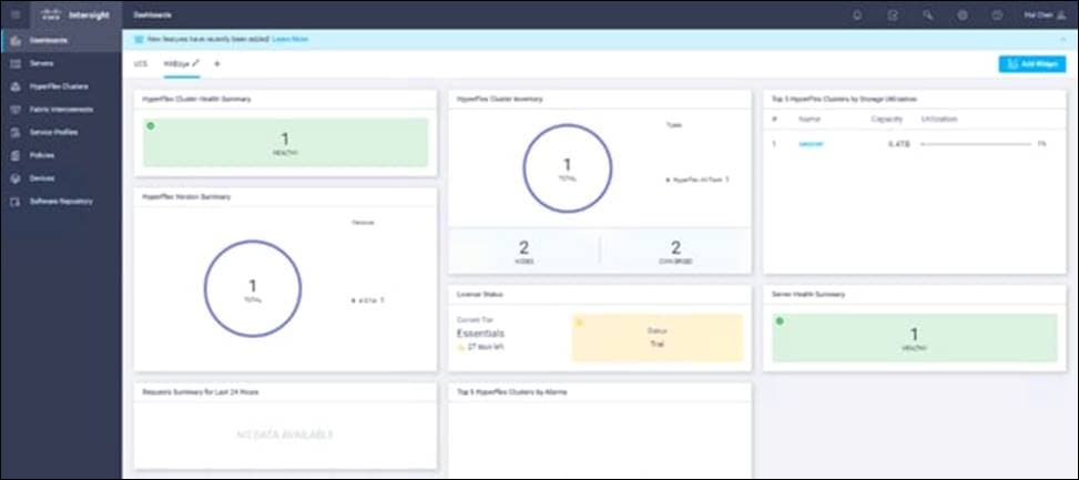
Cisco Intersight (https://intersight.com) is an API driven, cloud-based system management platform. It is designed to help organizations to achieve their IT management and operations with a higher level of automation, simplicity, and operational efficiency. It is a new generation of global management tool for the Cisco Unified Computing System (Cisco UCS) and Cisco HyperFlex systems and provides a holistic and unified approach to managing the customers’ distributed and virtualized environments. Cisco Intersight simplifies the installation, monitoring, troubleshooting, upgrade, and support for your infrastructure with the following benefits:
● Cloud Based Management: The ability to manage Cisco UCS and HyperFlex from the cloud provides the customers the speed, simplicity, and easy scaling in the management of their infrastructure whether in the datacenters or remote and branch office locations.
● Automation: Unified API in Cisco UCS and Cisco HyperFlex systems enables policy driven configuration and management of the infrastructure and it makes Intersight itself and the devices connected to it fully programmable and DevOps friendly.
● Analytics and Telemetry: Intersight monitors the health and relationships of all the physical and virtual infrastructure components. It also collects telemetry and configuration information for developing the intelligence of the platform in the way in accordance with Cisco information security requirements.
● Connected TAC: Solid integration with Cisco TAC enables more efficient and proactive technical support. Intersight provides enhanced operations automation by expediting sending files to speed troubleshooting.
● Recommendation Engine: Driven by analytics and machine learning, Intersight recommendation engine provides actionable intelligence for IT operations management from daily increasing knowledge base and practical insights learned in the entire system.
● Management as A Service: Cisco Intersight provides management as a service and is designed to be infinitely scale and easy to implement. It relieves users of the burden of maintaining systems management software and hardware.
Figure 4. Cisco Intersight
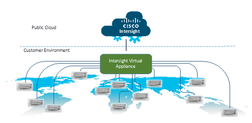
Intersight Virtual Appliance
The Cisco Intersight Virtual Appliance delivers the management features of Intersight for Cisco UCS and HyperFlex into the on-premise environment. It is deployed from a VMware OVA that enables the additional control to specify what data is sent back to Cisco with a single point of egress within the enterprises network. The virtual appliance form factor enables additional data locality, security, or compliance needs that are not completely met by connecting directly to intersight.com in the cloud. However, The Cisco Intersight Virtual Appliance is not intended for an environment with no external connectivity, the Cisco Intersight virtual appliance requires an internet connection back to Cisco and the cloud-based Intersight services for updates and to deliver some of the product features. Communication back to Cisco can be redirected via a proxy server if direct connectivity is not available or allowed by policy. Updates to the virtual appliance are automated and applied during a user specified recurring maintenance window. This connection also facilitates the streamlining of Cisco TAC services for Cisco UCS and HyperFlex systems, with features like automated support log collection.
Cisco Intersight Virtual Appliance OVA can be downloaded from Cisco website and can be deployed as a virtual machine in your existing environment. Cisco Intersight Virtual Appliance uses a subscription-based license delivered via Cisco Smart Licensing. After the installation of the appliance OVA is completed, you must connect the appliance to Cisco Intersight, and register the license as part of the initial setup process.
Figure 5. Cisco Intersight Virtual Appliance
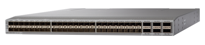
The Cisco Nexus® 9300-EX Series switches belongs to the fixed Cisco Nexus 9000 platform based on Cisco Cloud Scale technology. The platform supports cost-effective cloud-scale deployments, an increased number of endpoints, and cloud services. The platform is built on modern system architecture designed to provide high performance and meet the evolving needs of highly scalable data centers and growing enterprises.
Cisco Nexus 9300-EX series switches offer a variety of interface options to transparently migrate existing data centers from 100-Mbps, 1-Gbps, and 10-Gbps speeds to 25-Gbps at the server, and from 10- and 40-Gbps speeds to 50- and 100-Gbps at the aggregation layer. The platforms provide investment protection for customers, delivering large buffers, highly flexible Layer 2 and Layer 3 scalability, and performance to meet the changing needs of virtualized data centers and automated cloud environments.
Cisco provides two modes of operation for Cisco Nexus 9000 Series Switches. Organizations can use Cisco NX-OS Software to deploy the switches in standard Cisco Nexus switch environments (NX-OS mode). Organizations can also deploy the infrastructure that is ready to support the Cisco Application Centric Infrastructure (Cisco ACI™) platform to take full advantage of an automated, policy-based, systems-management approach (ACI mode).
The Cisco Nexus 93180YC-EX Switch is a 1-Rack-Unit (1RU) switch with latency of less than 1 microsecond that supports 3.6 Terabits per second (Tbps) of bandwidth and over 2.6 billion packets per second (bpps). The 48 downlink ports on the 93180YC-EX can be configured to work as 1-, 10-, or 25-Gbps ports, offering deployment flexibility and investment protection. The uplink can support up to six 40- and 100-Gbps ports, or a combination of 1-, 10-, 25-, 40-, 50, and 100-Gbps connectivity, offering flexible migration options. The switch has FC-FEC enabled for 25Gbps and supports up to 3m in DAC connectivity. Please check Cisco Optics Matrix for the most updated support.
Figure 6. Cisco Nexus 93180 YC-EX
RING is a cloud-scale, distributed software solution for petabyte-scale unstructured data storage. It is designed to create unbounded scale-out storage systems for the many petabyte-scale applications and use cases, both object and file, that are deployed in today’s enterprise data centers. RING is a fully distributed system deployed on industry standard hardware, starting with a minimum of three (3) storage servers and/or 200TB of usable capacity. It is designed to support an unbounded number of storage servers and can grow to 100’s of petabytes of storage capacity. RING has no single points of failure, and requires no downtime during any upgrades, scaling, planned maintenance or unplanned system events. With self-healing capabilities, it continues operating normally throughout these events. To match performance to increasing capacity, RING can also independently scale-out its access layer of protocol Connectors, to enable an even match of aggregate performance to the application load. RING provides data protection and resiliency through local or geo-distributed erasure-coding and replication, with services for continuous self-healing to resolve expected failures in platform components such as servers and disk drives. RING is fundamentally built on a scale-out object-storage layer that employs a second-generation peer-to-peer architecture. This approach uniquely distributes both the user data and the associated metadata across the underlying nodes to eliminate the typical central metadata database bottleneck. To enable file and object data in the same system, the RING integrates a virtual file system layer through an internal NoSQL scale-out database system, which provides POSIX-based access semantics using standard NFS, SMB and FUSE protocols with shared access to the files as objects using the REST protocol.
Figure 7. Scality RING Diagram
Scality has designed RING along the design criteria spearheaded by the leading cloud-scale service providers, such as Google, Facebook, and Amazon. RING leverages loosely-coupled, distributed systems designs that leverage commodity, mainstream hardware along the following key tenets:
● 100 percent parallel design for metadata and data - to enable scaling of capacity and performance to unbounded numbers of objects, with no single points of failures, service disruptions, or forklift upgrades as the system grows.
● Multi-protocol data access – to enable the widest variety of object, file, and host-based applications to leverage RING storage.
● Flexible data protection mechanisms - to protect a wide range of data types and sizes efficiently and durably.
● Self-healing from component failures – to provide high-levels of data durability, the system expects and tolerates failures and automatically resolves them.
● Hardware freedom – to provide optimal platform flexibility, eliminate lock-in and reduce TCO.
RING incorporates these design principles at multiple levels, to deliver the highest levels of data durability, at the highest levels of scale, for most optimal economics.
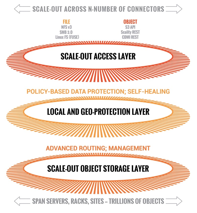
To scale both storage capacity and performance to massive levels, the Scality RING software is designed as a distributed, parallel, scale-out architecture with a set of intelligent services for data access and presentation, data protection and systems management. To implement these capabilities, RING provides a set of fully abstracted software services including a top-layer of scalable access services (Connectors) that provide storage protocols for applications. The middle layers are comprised of a distributed virtual file system layer, a set of data protection mechanisms to ensure data durability and integrity, self-healing processes and a set of systems management and monitoring services. At the bottom of the stack, the system is built on a distributed storage layer comprised of virtual storage nodes and underlying IO daemons that abstract the physical storage servers and disk drive interfaces.
At the heart of the storage layer is a scalable, distributed object key/value store based on a second-generation peer-to-peer routing protocol. This routing protocol ensures that store and lookup operations scale efficiently to very high numbers of nodes.
RING software is comprised of the following main components: RING Connectors, a distributed internal NoSQL database called MESA, RING Storage Nodes and IO daemons, and the Supervisor web-based management portal. The MESA database is used to provide the Scale-Out-File-System (SOFS) file system abstraction layer, and the underlying core routing protocol and Keyspace mechanisms are described later in this paper.
Figure 8. Scality Scale-out Architecture
The Connectors provide the data access endpoints and protocol services for applications that use RING for data storage. As a scale-out system, RING supports any number of Connectors and endpoints to support large and growing application workloads. The RING 7 release provides a family of object and file interfaces:
● AWS S3 API - a comprehensive implementation of the AWS S3 REST API, with support for the Bucket and Object data model, AWS style Signature v4/v2 authentication, and the AWS model of Identity and Access Management (IAM)
● http/REST (sproxyd) - the RING’s native key/value REST API, provides a flat object storage namespace with direct access to RING objects
● NFS v3 - SOFS volumes presented as a standard NFSv3 mount points
● SMB 3.0 - SOFS volumes presented as SMB Shares to Microsoft Windows clients. Scality implements a subset of the SMB 3.0 protocol.
● FUSE - SOFS volumes presented as a local Linux file system
● CDMI/REST - support for the SNIA CDMI REST interface, with full compatibility to SOFS file data
● S3 on SOFS - SOFS volumes may be accessed in read-only mode over the S3 protocol, for namespace and data sharing between objects and files
● NFS v4/v3 on S3 - S3 buckets may be exported as NFS v4/v3 mount points
Connectors provide storage services for read, write, delete and lookup for objects or files stored into the RING based on either object or POSIX (file) semantics. Applications can make use of multiple connectors in parallel to scale out the number of operations per second, or the aggregate throughput of the RING. A RING deployment may be designed to provide a mix of file access and object access (over NFS and S3 for example), simultaneously—to support multiple application use cases.
The heart of the ring is the Storage Nodes, that are virtual processes that own and store a range of objects associated with its portion of the RING’s keyspace. Each physical storage server (host) is typically configured with six (6) storage node processes (termed bizstorenode). Under the storage nodes are the storage daemons (termed biziod), which are responsible for persistence of the data on disk, in an underlying local standard disk file system. Each biziod instance is a low-level software process that manages the IO operations to a particular physical disk drive and maintains the mapping of object keys to the actual object locations on disk. Biziod processes are local to a given server, managing only local, direct-attached storage, and communicating only with Storage Nodes on the same server. The typical configuration is one biziod per physical disk drive, with support for up to hundreds of daemons per server, so the system can support very large, high-density storage servers.
Each biziod stores object payloads and metadata in a set of fixed size container files on the disk it is managing. With such containerization the system can maintain high-performance access even to small files, without any storage overhead. The bizoid deamons typically leverage low-latency flash (SSD or NVMe) devices to store the index files for faster lookup performance. The system provides data integrity assurance and validation through the use of stored checksums on the index and data container files, which are validated upon read access to the data. The use of a standard file system underneath biziod ensures that administrators can use normal operating system utilities and tools to copy, migrate, repair, and maintain the disk files if required.
The recommended deployment for systems that have both HDD and SSD media on the storage servers is to deploy a data RING on HDD, and the associated metadata in a separate RING on SSD. Typically, the requirements for metadata are approximately 2 percent of the storage capacity of the actual data, so the sizing of SSD should follow that percentage for best effect. Scality can provide specific sizing recommendations based on the expected average file sizes, and number of files for a given application.
Managing and monitoring the RING is enabled through a cohesive suite of user interfaces, built on top of a family of RESTful interfaces termed the Supervisor API (SupAPI). The SupAPI provides an API based method that may be accessed from scripts, tools, and frameworks for gathering statistics, metrics, health check probes and alerts, and for provisioning new services on the RING. The SupAPI is also enabled with Role Based Access Control (RBAC), by supporting an administrator identity to provide access control privileges for Super-Admin and Monitor admin user Roles.
RING provides a family of tools that use the SupAPI for accessing the same information and services. RING 7 includes the new Scality Supervisor, a browser-based portal for both systems monitoring and management of Scality components. In RING 7, the Supervisor now provides capabilities across object (S3) and file (NFS, SMB, FUSE) Connectors including integrated dashboards including Key Performance Indicators (KPIs) with trending information such as Global Health, Performance, Availability and Forecast. The Supervisor also includes provisioning capabilities to add new servers in the system and a new zone management module to handle customer failure domains for multi-site deployments.
Figure 9. Supervisor Web GUI
RING Supervisor also includes an Advanced Monitoring dashboard where all collected metrics can be graphed and analyzed component per-component and per-server. This is based on a very powerful graphing engine that has access to thousands of metrics.
A new S3 Service Management console portal is provided to manage the integrated AWS Identity and Access Management (IAM) model of S3 multi-tenancy in the RING. This provides two-level management of Accounts, Users/Groups and IAM access control policies. The S3 Console may also be easily customized for white-labeling purposes.
Figure 10. S3 Service Management Console
A new Scality S3 Browser is also provided to browse S3 buckets, upload and download object data, and for managing key S3 features such as bucket versioning, CORS, editing of metadata attributes and tagging. The S3 Browser is an S3 API client that runs on the S3 user browser and is accessible to both the Storage administrator and also to the S3 end-user.
Figure 11. Scality S3 Browser
A scriptable Command Line Interface (CLI) called RingSH is also provided, as well as an SNMP compatible MIB and traps interface for monitoring from standard SNMP consoles. RING is designed to be self-managing and autonomous to free administrators to work on other value-added tasks, and not worry about the component level management tasks common with traditional array-based storage solutions.
S3 Connector: AWS S3 Storage with Identity and Access Management (IAM)
The Scality S3 Connector provides a modern S3 compatible application interface to the Scality RING. The AWS S3 API has now become the industry’s default cloud storage API and has furthermore emerged as the standard RESTful dialect for object storage as NFS was for the NAS generation. The S3 Connector is built on a distributed scale-out architecture to support very high levels of application workloads and concurrent user access. This is based on a highly-available, high-performance metadata engine that can also be scaled-out for increased performance. Deployments can be geo-replicated deployments to enable highly-available disaster recovery solutions, for both Metro-Area Network environments (stretched deployments), as well as Cross Region Replication (CRR) asynchronous replication of individual S3 buckets or a full site.
The Scality S3 Connector also provides a full implementation of the AWS multi-tenancy and identity management (AWS IAM) model with federated authentication to LDAP and Active Directory to integrate into enterprise deployment environments. In addition to the RING Supervisor management UI, the S3 Service Provider UI is a web-based user interface to manage multi-tenancy accounts, users, group, and policies. To support enterprise security, development and operational methodologies, the S3 Connector on RING supports:
● Integration with Enterprise directory/security servers: most commonly Microsoft Active Directory or LDAP servers. Federated authentication integration is supported through a SAML 2.0-compatible Identity Provider such as Microsoft ADFS, and many other SAML compatible products, to enable a complete Single Sign-On (SSO) solution.
● Secure Multi-tenancy support: through IAM Accounts, secure access keys, Users, Groups, access control policies and v4 authentication per-tenant, bucket encryption (integrated with corporate KMS solutions) and auditing
● Utilization reporting to enable chargeback: the S3 Connector Utilization API provides an extended API for reporting on comprehensive usage metrics including capacity, #objects, bandwidth and S3 operations (per unit time). This provides all of the metrics required for consumption into corporate tools for chargeback calculations.
● High-performance, scale-out access: to support many corporate applications and workloads simultaneously reading and writing to the S3 service
● Highly-available disaster-recovery solutions: enabled deployments through multi-data center deployments to provide availability in the event of site failure
● Bucket Versioning via the S3 API, and for Cross Region Replication (CRR) of Buckets through the S3 API, this provides bucket-level asynchronous replication to another S3/RING deployment.
● S3 Object Lock API: designed to render data immutable, by preventing data from being deleted or overwritten for a period of time or indefinitely. Combined with backup solutions like Veeam Backup and Replication v10, Scality RING8 provides for an air-gapped, tamper-proof backup data that stays immune to ransomware, thereby mitigating its impact and offering a swift recovery path in case of an attack, and therefore thwarting malicious ransomware attacks.
RING supports native file system access to RING storage through the integrated Scale-Out-File-System (SOFS) with NFS, SMB and FUSE Connectors for access over these well-known file protocols. SOFS is a POSIX compatible, parallel file system that provides file storage services on the RING without the need for external gateways.
SOFS is more precisely a virtual file system, which is based on an internal distributed database termed MESA (table in Spanish) on top of the RING’s storage services. MESA is a distributed, semi-structured database that is used to store the file system directories and file inode structures. This provides the virtual file system hierarchical view, with the consistency required for file system data, by ensuring that file system updates are always atomic. This means that updates are either committed or rolled back entirely—which guarantees the file system is never left in an intermediate or inconsistent state. A key advantage for scaling is that MESA is itself is distributed as a set of objects across all of the RING’s storage node in a shared nothing manner to eliminate any bottlenecks or limitations.
File system lookups are performed using the RING’s standard peer-to-peer routing protocol. For fast access performance, SOFS metadata is recommended to be stored on flash storage, typically on its own dedicated SSD drives in the storage servers, with the SOFS file payloads stored in the data RING on hard disk drives (HDDs). SOFS works directly with the data protection and durability mechanisms present in the RING, including replication and configurable Erasure Coding schemas.
SOFS can be provisioned into one or more volumes and can be scaled in capacity as needed to support application requirements. Each volume can be accessed by any number of Connectors to support the incoming load workload, even with mixed protocols (NFS, SMB or FUSE). RING can support an enormous number of volumes (up to 2^32) and can grow to billions of files per volume. There is no need to pre-configure volumes for capacity (the RING effectively supports thin-provisioning of volumes). Volumes will utilize the RING’s storage pool to expand as needed when files are created and updated. For efficient storage of very large files, the RING supports the concept of sparse files, effectively files combined from multiple individual data-stripes.
While multiple Connectors may be used to simultaneously access a volume, the RING currently supports scale-out access for multiple concurrent readers, and a new File Access Coordination mode that allows multiple readers on a file while it is being written from another Connector. This is useful in use-cases such as video streaming where very large video files are written over the course of minutes or hours, but the file must be accessed for content distribution before the write is complete. Multiple Connectors attempt to write to the same directory or one per file within a directory, SOFS maintains view consistency across multiple connectors. By supporting scale-out across any number of Connectors, SOFS throughput can be scaled out to support increasing workload demands. When performance saturation is reached, it is always possible to add more connectors or storage nodes (and disk spindles) to the RING to further increase throughput into the system. The system can achieve 10’s of Gigabytes per second of aggregate throughput for parallel workloads through this architecture.
SOFS provides volume-level utilization metering and quota support, in addition to User and Group (uid/gid) quotas. This enables administrators to effectively use the concept of volumes to meter, report, and limit space (capacity) usage at the volume level. This is useful in a multi-tenant environment where multiple applications or use cases are sharing the same RING, but accessing data stored in their own volume.
SOFS also provides integrated failover and load balancer services for the NFS and SMB Connectors. The load balancer uses an integrated DNS service to expose one or more service names (e.g., sofs1.companyname. com) on Virtual IP addresses (VIPs), which can be mounted as NFS mount points or SMB shares. The load balancer can be configured with multiple underlying NFS or SMB connector real IP addresses, and provides load balancing of file traffic across these SOFS connectors. In combination with the RING 6.0 Folder Scale-out feature, this also provides transparent multi-connector access to a single folder, as well as enabling failover. In the event one of the underlying NFS or SMB Connectors becomes non-responsive, the load balancer can select another Connector IP address as the access point for the request.
Intelligent Data Durability and Self-Healing
RING is designed to expect and manage a wide range of component failures including disks, server networks and even across multiple data centers, while ensuring that data remains durable and available during these conditions. RING provides data durability through a set of flexible data protection mechanisms optimized for distributed systems, including replication, erasure coding and geo-replication capabilities that allow applications to select the best data protection strategies for their data. These flexible data protection mechanisms implement Scality’s design principle to address a wide spectrum (80 percent) of storage workloads and data sizes. A full description of multi-site data protection is provided in the next section, Multi-Site Geo-Distribution.
Replication Class of Service (COS)
To optimize data durability in a distributed system, the RING employs local replication, or the storage of multiple copies of an object within the RING. RING will attempt to spread these replicas across multiple storage nodes, and across multiple disk drives, in order to separate them from common failures (assuming sufficient numbers of servers and disks are available). RING supports six Class-of-Service levels for replication (0-5), indicating that the system can maintain between 0 to 5 replicas (or 1-6 copies) of an object. This allows the system to tolerate up to 5 simultaneous disk failures, while still preserving access and storage of the original object. Note that any failure will cause the system to self-heal the lost replica, to automatically bring the object back up to its original Class-of-Service, as fast as possible.
While replication is optimal for many use cases where the objects are small, and access performance is critical, it does impose a high storage overhead penalty compared to the original data. For example, a 100KB object being stored with a Class-of-Service=2 (2 extra copies so 3 total), will therefore consume 3 x 100KB = 300KB of actual physical capacity on the RING, in order to maintain its 3 replicas. This overhead is acceptable in many cases for small objects but can become a costly burden for megabyte or gigabyte level video and image objects. In this case, paying a penalty of 200% to store a 1GB object since it will require 3GB of underlying raw storage capacity for its 3 replicas. When measured across petabytes of objects, this becomes a significant cost burden for many businesses, requiring a more efficient data protection mechanism.
Scality’s erasure coding (EC) provides an alternative data protection mechanism to replication that is optimized for large objects and files. RING implements Reed-Solomon erasure coding6 techniques, to store large objects with an extended set of parity chunks, instead of multiple copies of the original object. The basic idea with erasure coding is to break an object into multiple chunks (m) and apply a mathematical encoding to produce an additional set of parity chunks (k). A description of the mathematical encoding is beyond the scope of this paper, but they can be simply understood as an extension of the XOR parity calculations used in traditional RAID. The resulting set of chunks, (m+k) are then distributed across the RING nodes, providing the ability to access the original object as long as any subset of m data or parity chunks are available. Stated another way, this provides a way to store an object with protection against k failures, with only k/m overhead in storage space.
Many commercial storage solutions impose a performance penalty on reading objects stored through erasure coding, due to the fact that all of the chunks, including the original data, are encoded before they are stored. This requires mandatory decoding on all access to the objects, even when there are no failure conditions on the main data chunks. With Scality’s EC, the data chunks are stored in the clear, without any encoding, so that this performance penalty is not present during normal read accesses. This means that erasure coded data can be accessed as fast as other data, unless a data chunk is missing which would require a parity chunk to be accessed and decoded. In summary, for single-site data protection, Scality’s replication and erasure coded data protection mechanisms can provide very high-levels of data durability, with the ability to trade-off performance and space characteristics for different data types.
Note that replication and erasure coding may be combined, even on a single Connector, by configuring a policy for the connector to store objects below a certain size threshold with a replication CoS, but files above the file size limit with a specific erasure coding schema. This allows the application to simply store objects without worrying about the optimal storage strategy per object, with the system managing that automatically.
Note that RING does not employ traditional RAID based data protection techniques. While RAID has served the industry well in legacy NAS and SAN systems, industry experts have written at large about the inadequacies of classical RAID technologies when employed on high-density disk drives, in capacity-optimized and distributed storage systems. These deficiencies include higher probabilities of data loss due to long RAID rebuild times, and the ability to protect against only a limited set of failure conditions (for example, only two simultaneous disk failures per RAID6 group). Further information and reading on the limitations of RAID as a data protection mechanism on high-capacity disk drives is widely available
RING provides self-healing processes that monitor and automatically resolve component failures. This includes the ability to rebuild missing data chunks due to disk drive or server failures, rebalance data when nodes leave and join the RING, and to proxy requests around component failures. In the event a disk drive or even a full server fails, background rebuild operations are spawned to restore the missing object data from its surviving replicas or erasure coded chunks. The rebuild process completes when it has restored the original Class of Service - either the full number of replicas or the original number of erasure coded data and parity chunks. A local disk failure can also be repaired quickly on a node (distinct from a full distributed rebuild), through the use of an in-memory key map maintained on each node. Nodes are also responsible for automatically detecting mismatches in their own Keyspace, rebalancing keys and for establishing and removing proxies during node addition and departure operations. Self-healing provides the RING with the resiliency required to maintain data availability and durability in the face of the expected wide set of failure conditions, including multiple simultaneous component failures at the hardware and software process levels.
To optimize rebuilds as well as mainline IO performance during rebuilds, RING utilizes the distributed power of the entire storage pool. The parallelism of the underlying architecture pays dividends by eliminating any central bottlenecks that might otherwise limit performance or cause contention between servicing application requests, and normal background operations such as rebuilds, especially when the system is under load. To further optimize rebuild operations, the system will only repair the affected object data, not the entire set of disk blocks, as is commonly the case in RAID arrays. Rebuilds are distributed across multiple servers and disks in the system, to utilize the aggregate processing power and available IO of multiple resources in parallel, rather than serializing the rebuilds onto a single disk drive.
By leveraging the entire pool, the impact of rebuilding data stored either with replication or erasure coding is minimized since there will be relatively small degrees of overlap between disks involved in servicing data requests, and those involved in the rebuilds.
Scality RING Multi-Site Deployments
To support multi data center deployments with site protection and complete data consistency between all sites, the RING natively supports a stretched (synchronous) deployment mode across sites. In this mode, a single logical RING is deployed across multiple data centers, with all nodes participating in the standard RING protocols as if they were local to one site.
When a stretched RING is deployed with EC, it provides multiple benefits including full site-level failure protection, active/active access from both data centers, and dramatically reduced storage overhead compared to mirrored RINGs. An erasure coding schema for a three-site stretched RING of 7+5 would provide protection against one complete site failure, or up to four disk/server failures per site, plus one additional disk/server failure in another site, with approximately 70 percent space overhead. This compares favorably to a replication policy that might require 300-400 percent space overhead, for similar levels of protection across these sites.
File System (SOFS) Multi-Site Geo-Distribution
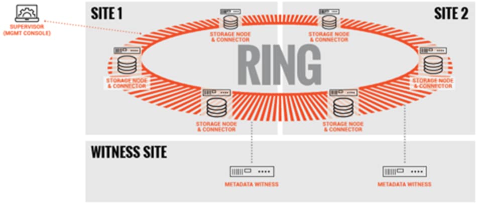
The Scality RING can be stretched across 2 to 3 sites within a Metro-Area Network (MAN) to provide full site failover, should the latency between the several sites go above 10ms. The stretched architecture provides zero RTO and RPO since the failover is automatized. This is the same for the failback procedure since when the lost site is recovered, the system will automatically recover the data. For the two-site stretched architecture only and to manage the mitigation between the 2 sites, 2 witness servers will be needed.
The 2 stretched sites + witness is an Active / Active replication system based on a synchronous replication.
Figure 12. SOFS – Two-site Stretched

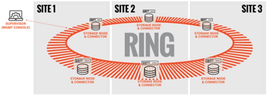
The 3 stretched sites are an Active / Active replication system based on a synchronous replication.
Figure 13. SOFS – Three-Site Stretched
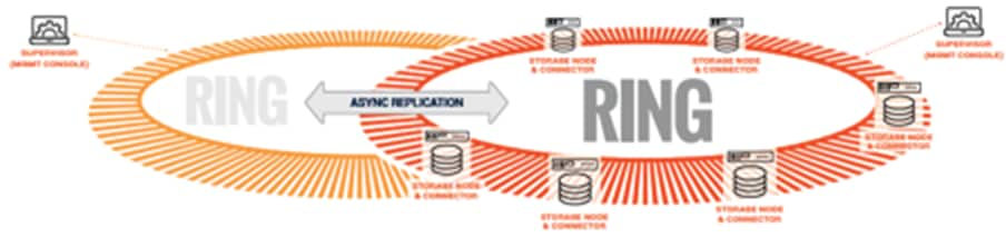
For high latency between sites, Scality supports SOFS 2 Sites Full Asynchronous replication mechanism at Scale to enable the replication of massive amount of file data across the 2 sites. Scality also supports a Full Diff mechanism that can compare at scale the content of the 2 sites to ensure the data are effectively replicated. Should one site be fully lost, Scality provides a mechanism to fully reconstruct the lost site.
To manage replication burst, Scality integrates a back-pressure system to be sure your production network link won’t be overloaded by the replication itself and at the same time will respect the RPO defined during the setup of the installation. This feature enables the Disaster Recovery (DR) feature by providing Failover and Failback system to recover in case of partial or full loss.
The 2 sites with high latency between them are an Active / Passive replication system based on an asynchronous replication.
Figure 14. SOFS – Two-Site Asynchronous Replication
S3 Object Multi-Site Geo-Distribution
The same multi-site architectures are supported for S3 as with SOFS, both synchronous & asynchronous. The first one with a stretched solution on two and three sites with no RPO and no RTO. As for SOFS, a stretched architecture is available within a MAN to provide full site failover. Should the latency between the several sites goes above 10ms. For the two-site stretched architecture only and to manage the mitigation between the 2 sites, 1 witness server will be needed.
The 2 stretched sites + witness is an Active / Active replication system based on a synchronous replication.
Figure 15. S3 – Two-site Stretched
The 3 stretched sites are an Active / Active replication system based on a synchronous replication.
Figure 16. S3 – Three-Site Stretched
For high latency between sites (such as on a Wide Area Network - WAN), Scality supports the S3 2 Sites Full Asynchronous replication mechanism at Scale to enable the replication of massive amount of data across the 2 sites. This system is based on the S3 CRR design to replicate a bucket between 2 sites. For site replication, Scality developed its own system to support site replication instead of just bucket. This feature enables the Disaster Recovery (DR) feature by providing Failover and Failback system to recover in case of partial or fully (flooding, fire, and so on) lost.
The 2 sites with high latency between them are an Active / Passive replication system based on an asynchronous replication.
Figure 17. S3 – Two-Site Asynchronous Replication
Scality NAS Archiver makes it easy to identify and migrate inactive data automatically and transparently to Scality RING, freeing-up premium primary storage capacity while cutting down overall backup and operating costs.
Scality NAS Archiver is a software-based fi le archiving solution that is designed to meet the needs of today’s modern data center, capitalizing on the benefits of the RING platform. This intelligent file archiving system maximizes the value of existing primary storage by removing the burden of stale data wasting space and compromising performance. Scality NAS Archiver offers an optimal solution for NAS offload and archiving, ensuring that data migration from the NAS to the RING stays perfectly seamless and totally transparent, with no impact to applications it serves.
The Scality NAS Archiving solution provides such a compelling TCO savings for users of enterprise NAS systems that pays for itself and more. It provides not only a transparent two-tier storage solution, preserving the normal performance and access characteristics of the NAS filers for users and applications, but also introduces a scalable, long-term, durable, and cost-effective solution for archiving on the RING object storage solution. Perhaps more important than the direct TCO savings, the NAS filer now has 60-80% free capacity, which can be used for additional Tier 1 file data – this opens up new applications and use-cases that the enterprise can use for its key business goals. Moreover, while all data archived to Scality RING is fully and seamlessly accessible through the NAS without any changes, this also provides a super optimal zero RPO/RTO solution in the event the NAS filer fails or becomes inaccessible.
In this architecture, we have Scality RING and Scality NAS Archiver deployed on Cisco UCS with Cisco Intersight and Terraform provider for Cisco Intersight. We automatically have setup three Cisco UCS C240 M5L server with Terraform provider for Cisco Intersight, simplifying the process of orchestrating a scale-out storage environment. All three servers were installed with the latest Red Hat Enterprise Linux 7 operating system.
We deployed manually Cisco Intersight virtual Appliance and Terraform as virtual machines. In addition, we automatically installed three virtual machines with Terraform for VMware vSphere, covering the Scality Supervisor, Scality NAS Archiver SQL server, and Scality NAS Archiver Portal. All virtual machines were deployed on a Cisco UCS C220 M5 server, connected to a pair of Cisco Nexus switches.
We’ve setup Scality NAS Archiver with a virtual machine for the SQL database and a virtual machine for the Scality NAS Archiver Portal server to show in an example how to archive data from a Windows File Server to Scality RING.
Figure 18. Solution Overview
This Cisco Validated Design provides a comprehensive, end-to-end guide for deploying Scality RING and Scality NAS Archiver on Cisco UCS C240 M5 with Cisco Intersight and Terraform provider for Cisco Intersight.
The 3-node Scality RING solution has various options to scale capacity. The tested configuration uses ARC (Advanced Resiliency Configuration) 7+5 and COS 3 replication for small objects. A base capacity summary for the tested solution is listed in Table 1. Because of the smallest Scality RING license of 200 TB usable, there is no option to use smaller drives than 10 TB.
| HDD Type |
Number of Disks |
Usable Capacity |
| 10 TB 7200-rpm LFF NL-SAS |
36 |
196 TB |
| 12 TB 7200-rpm LFF NL-SAS |
236 TB |
|
| 14 TB 7200-rpm LFF NL-SAS |
275 TB |
|
| 16 TB 7200-rpm LFF NL-SAS |
314 TB |
The solution setup consists of multiple parts. It covers basic setup of the network components, policies and profiles setup, installations of various parts as well as functional tests and high availability testing. The high-level flow of the solution setup is as follows:
1. Install and configure Cisco Nexus 93180YC-EX.
2. Deploy Cisco Intersight virtual Appliance.
3. Deploy Terraform virtual machine.
4. Install and configure Cisco UCS C240 M5 with Cisco Intersight and Terraform provider for Cisco Intersight.
5. Deploy Scality RING Supervisor, Scality NAS Archiver SQL virtual machine, and Scality NAS Archiver Portal server virtual machine through Terraform for VMware vSphere.
6. Configure and install Scality RING.
7. Configure and install Scality NAS Archiver.
8. Functional tests of the whole solution.
9. Performance tests for S3 and NFS.
10. High Availability testing of the solution.
The following sections detail the physical hardware, software revisions, and firmware versions required to install a single Scality RING cluster on Cisco UCS as well Scality NAS Archiver. This is specific to the solution built in this CVD.
Table 2. Hardware Components used in this CVD
| Component |
Model |
Quantity |
Comments |
| Switches |
Cisco Nexus 93180YC-EX |
2 |
|
| Cisco UCS |
Cisco UCS C240 M5L |
3 |
Each Node: 2 x Intel Xeon Silver 4214 (2.2 GHz, 12 Cores) 256 GB Memory Cisco 12G Modular Raid Controller with 2GB cache 2 x 960 GB M.2 6 Gbps SATA SSD for Metadata 2 x 960 GB 6 Gbps SATA SSD for System 12 x 10 TB 12 Gbps NL-SAS HDD for Data 1 x VIC 1455 |
| Cisco UCS |
Cisco UCS C220 M5S |
1 |
2 x Intel Xeon Platinum 8180 (2.5 GHz, 28 Cores) 192 GB Memory Cisco 12G Modular Raid Controller with 2GB cache 2 x 480 GB 6 Gbps SATA SSD for System 3 x 3.8 TB 6 Gbps SATA SSD for Data 1 x VIC 1455 |
| Cisco Intersight Virtual Appliance |
Virtual Machine |
1 |
16 vCPU 32 GB Memory 500 GB Disk 1 x Network |
| Terraform |
Virtual Machine |
1 |
2 vCPU 16 GB Memory 100 GB Disk 1 x Network |
| Scality Supervisor |
Virtual Machine |
1 |
4 vCPU 16 GB Memory 800 GB Disk 2 x Network |
| Scality NAS Archiver SQL |
Virtual Machine |
1 |
8 vCPU 16 GB Memory 250 GB Disk 1 x Network |
| Scality NAS Archiver Portal |
Virtual Machine |
1 |
4 vCPU 8 GB Memory 80 GB Disk 1 x Network |
The required software distribution versions are listed in Table 3.
| Layer |
Component |
Version or Release |
| Cisco UCS C240 M5L |
Firmware Version |
4.1(1f) |
| Cisco UCS C220 M5SX |
Firmware Version |
4.1(1f) |
| Network Nexus 93180YC-EX |
BIOS |
07.67 |
| NXOS |
9.3(4) |
|
| Cisco Intersight Virtual Appliance |
Version |
1.0.9-164 |
| Software |
Terraform |
0.13.2 |
| Software |
Terraform Provider for Intersight |
0.1.3 |
| Software |
Scality RING |
8.2 |
| Software |
Scality NAS Archiver |
8.2 |
| Software |
Red Hat Enterprise Linux |
7.8 |
| Hypervisor |
VMware ESXi |
6.7 Update 3 |
| Management Server |
VMware vCenter |
6.7 Update 3 |
The solution contains one topology configuration. There are three Cisco UCS C240 M5 and one Cisco UCS C220 M5 connected to a pair of Cisco Nexus 93180YC-EX switches. Each Cisco UCS C240 M5 and C220 M5 server relates to one 25-Gbps cable to each Cisco Nexus 93180YC-EX. All three Cisco UCS C240 M5 server use 802.3ad bonding to achieve high availability and high performance. The Cisco UCS C220 M5 server uses two active network interfaces configured under ESXi to achieve in the same way high availability and high performance.
The following diagram illustrates the details of the configuration.
Figure 19. Datacenter Topology
VLANs and Subnets
For the base configuration multiple VLANs need to be carried to the Cisco UCS domain from the upstream LAN, and these VLANs are also defined in the Cisco UCS configuration. Table 4 lists the VLANs created by the Cisco Intersight used in this CVD and their functions:
| VLAN Name |
VLAN ID |
Subnet |
Purpose |
| Management/Client |
205 |
172.16.21.0/24 GW 172.16.21.1 |
Cisco UCS CIMC management interfaces Cisco Intersight Terraform Client network for Scality RING, Scality NAS Archiver Windows File Server for Scality NAS Archiver |
| Storage |
206 |
172.16.22.0/24 GW 172.16.22.1 |
Storage network for Scality RING |
Jumbo Frames
All traffic traversing the Client and Storage VLAN and subnet is configured by default to use jumbo frames, or to be precise, all communication is configured to send IP packets with a Maximum Transmission Unit (MTU) size of 9000 bytes. Using a larger MTU value means that each IP packet sent carries a larger payload, therefore transmitting more data per packet, and consequently sending and receiving data faster.
Naming Scheme and DNS
DNS servers are highly recommended to be configured for querying Fully Qualified Domain Names (FQDN). DNS records need to be created prior to beginning the installation. At a minimum, it is highly recommended to create A records and reverse PTR records.
Use Table 5 to gather the required DNS information for the installation and list the information required for this CVD:
Table 5. DNS Server Information
| Item |
Name |
| DNS Server |
192.168.10.51 |
| DNS Domain |
sjc02dmz.net |
| vCenter Server Name |
sjc02dmz-vcsa |
| Cisco Nexus 93180YC-EX #1 |
sjc02dmz-f9-n93180ycex-a |
| Cisco Nexus 93180YC-EX #2 |
sjc02dmz-f11-n93180ycex-b |
| Cisco Intersight virtual Appliance |
sjc02dmz-f11-intersight |
| Cisco UCS C240 M5 #1 |
sjc02dmz-f11-storage1 |
| Cisco UCS C240 M5 #2 |
sjc02dmz-f11-storage2 |
| Cisco UCS C240 M5 #3 |
sjc02dmz-f11-storage3 |
| Cisco UCS C220 M5 |
sjc02dmz-f11-esxi |
| Cisco Intersight |
sjc02dmz-f11-intersight |
| Terraform |
sjc02dmz-f11-terraform |
| Scality Supervisor |
sjc02dmz-f11-supervisor |
| Scality NAS Archiver SQL Server |
sjc02dmz-f11-sql |
| Scality NAS Archiver Portal Server |
sjc02dmz-f11-portal |
| Windows File Server for Scality NAS Archiver |
sjc02dmz-f11-winnas |
Cabling
The physical layout of the solution was previously described in section Topology Overview. The Cisco Nexus switches, and the Cisco UCS server need to be cabled properly before beginning the installation activities. Table 6 provides the cabling map for installation of a Scality RING solution on Cisco UCS.
Table 6. Cabling Map Cisco Nexus 93180YC-EX
| Device |
Port |
Connected To |
Port |
Note |
| sjc02dmz-f9-n93180ycex-a |
11 |
sjc02dmz-f11-esxi |
Port 0 |
|
| sjc02dmz-f9-n93180ycex-a |
12 |
sjc02dmz-f11-storage1 |
Port 0 |
|
| sjc02dmz-f9-n93180ycex-a |
13 |
sjc02dmz-f11-storage2 |
Port 0 |
|
| sjc02dmz-f9-n93180ycex-a |
14 |
sjc02dmz-f11-storage3 |
Port 0 |
|
| sjc02dmz-f9-n93180ycex-a |
49 |
sjc02dmz-f11-n93180ycex-b |
Eth1/49 |
vPC Peer Link |
| sjc02dmz-f9-n93180ycex-a |
50 |
sjc02dmz-f11-n93180ycex-b |
Eth1/50 |
vPC Peer Link |
| sjc02dmz-f11-n93180ycex-b |
11 |
sjc02dmz-f11-esxi |
Port 2 |
|
| sjc02dmz-f11-n93180ycex-b |
12 |
sjc02dmz-f11-storage1 |
Port 2 |
|
| sjc02dmz-f11-n93180ycex-b |
13 |
sjc02dmz-f11-storage2 |
Port 2 |
|
| sjc02dmz-f11-n93180ycex-b |
14 |
sjc02dmz-f11-storage3 |
Port 2 |
|
| sjc02dmz-f11-n93180ycex-b |
49 |
sjc02dmz-f9-n93180ycex-a |
Eth1/49 |
vPC Peer Link |
| sjc02dmz-f11-n93180ycex-b |
50 |
sjc02dmz-f9-n93180ycex-a |
Eth1/50 |
vPC Peer Link |
Deployment Hardware and Software
This section provides the details to configure a fully redundant, highly available Cisco UCS configuration.
● Initial setup of Cisco Nexus 93180YC-EX Switch A and B
Configure Cisco Nexus 93180YC-EX Switch A and B
Both Cisco UCS Fabric Interconnect A and B are connected to two Cisco Nexus 93180YC-EX switches for connectivity to applications and clients. The following sections describe the setup of both Cisco Nexus 93180YC-EX switches.
Initial Setup of Cisco Nexus 93180YC-EX Switch A and B
To configure Switch A, connect a Console to the Console port of each switch, power on the switch and follow these steps:
1. Type yes.
2. Type n.
3. Type n.
4. Type n.
5. Enter the switch name.
6. Type y.
7. Type your IPv4 management address for Switch A.
8. Type your IPv4 management netmask for Switch A.
9. Type y.
10. Type your IPv4 management default gateway address for Switch A.
11. Type n.
12. Type n.
13. Type y for ssh service.
14. Press <Return> and then <Return>.
15. Type y for ntp server.
16. Type the IPv4 address of the NTP server.
17. Type in L2 for interface layer.
18. Press <Return> and again <Return>.
19. Check the configuration and if correct then press <Return> and again <Return>.
The complete setup looks like the following:
---- System Admin Account Setup ----
Do you want to enforce secure password standard (yes/no) [y]:
Enter the password for "admin":
Confirm the password for "admin":
---- Basic System Configuration Dialog VDC: 1 ----
This setup utility will guide you through the basic configuration of
the system. Setup configures only enough connectivity for management
of the system.
Please register Cisco Nexus9000 Family devices promptly with your
supplier. Failure to register may affect response times for initial
service calls. Nexus9000 devices must be registered to receive
entitled support services.
Press Enter at any time to skip a dialog. Use ctrl-c at anytime
to skip the remaining dialogs.
Would you like to enter the basic configuration dialog (yes/no): yes
Create another login account (yes/no) [n]:
Configure read-only SNMP community string (yes/no) [n]:
Configure read-write SNMP community string (yes/no) [n]:
Enter the switch name : sjc02dmz-f9-n93180ycex-a
Continue with Out-of-band (mgmt0) management configuration? (yes/no) [y]:
Mgmt0 IPv4 address : 172.16.16.4
Mgmt0 IPv4 netmask : 255.255.255.0
Configure the default gateway? (yes/no) [y]:
IPv4 address of the default gateway : 192.168.12.3
Configure advanced IP options? (yes/no) [n]:
Enable the telnet service? (yes/no) [n]:
Enable the ssh service? (yes/no) [y]:
Type of ssh key you would like to generate (dsa/rsa) [rsa]:
Number of rsa key bits <1024-2048> [1024]:
Configure the ntp server? (yes/no) [n]: y
NTP server IPv4 address : 173.38.201.115
Configure default interface layer (L3/L2) [L3]: L2
Configure default switchport interface state (shut/noshut) [shut]:
Configure CoPP system profile (strict/moderate/lenient/dense) [strict]:
The following configuration will be applied:
password strength-check
switchname sjc02dmz-f9-n93180ycex-a
vrf context management
ip route 0.0.0.0/0 192.168.12.3
exit
no feature telnet
ssh key rsa 1024 force
feature ssh
ntp server 173.38.201.115
no system default switchport
system default switchport shutdown
copp profile strict
interface mgmt0
ip address 172.16.16.4 255.255.255.0
no shutdown
Would you like to edit the configuration? (yes/no) [n]:
Use this configuration and save it? (yes/no) [y]:
[########################################] 100%
Copy complete.
User Access Verification
Sjc02dmz-f9-n93180ycex-a login:
![]() Repeat steps 1-19 for the Cisco Nexus 93180YC-EX Switch B with the exception of configuring a different IPv4 management address in step 7.
Repeat steps 1-19 for the Cisco Nexus 93180YC-EX Switch B with the exception of configuring a different IPv4 management address in step 7.
Enable Features on Cisco Nexus 93180YC-EX Switch A and B
To enable the features UDLD, VLAN, LACP, HSRP, VPC, and Jumbo Frames, connect to the management interface via ssh on both switches and follow these steps on both Switch A and B:
Switch A
sjc02dmz-f9-n93180ycex-a # configure terminal
Enter configuration commands, one per line. End with CNTL/Z.
sjc02dmz-f9-n93180ycex-a (config)# feature udld
sjc02dmz-f9-n93180ycex-a (config)# feature interface-vlan
sjc02dmz-f9-n93180ycex-a(config)# feature lacp
sjc02dmz-f9-n93180ycex-a(config)# feature vpc
sjc02dmz-f9-n93180ycex-a(config)# feature hsrp
sjc02dmz-f9-n93180ycex-a(config)# system jumbomtu 9216
sjc02dmz-f9-n93180ycex-a(config)# spanning-tree port type edge bpduguard default
sjc02dmz-f9-n93180ycex-a(config)# spanning-tree port type edge bpdufilter default
sjc02dmz-f9-n93180ycex-a(config)# port-channel load-balance src-dst ip-l4port-vlan
sjc02dmz-f9-n93180ycex-a(config)# exit
sjc02dmz-f9-n93180ycex-a#
Switch B
sjc02dmz-f11-n93180ycex-b# configure terminal
Enter configuration commands, one per line. End with CNTL/Z.
sjc02dmz-f11-n93180ycex-b(config)# feature udld
sjc02dmz-f11-n93180ycex-b(config)# feature interface-vlan
sjc02dmz-f11-n93180ycex-b(config)# feature lacp
sjc02dmz-f11-n93180ycex-b(config)# feature vpc
sjc02dmz-f11-n93180ycex-b(config)# feature hsrp
sjc02dmz-f11-n93180ycex-b(config)# system jumbomtu 9216
sjc02dmz-f11-n93180ycex-b(config)# spanning-tree port type edge bpduguard default
sjc02dmz-f11-n93180ycex-b(config)# spanning-tree port type edge bpdufilter default
sjc02dmz-f11-n93180ycex-b(config)# port-channel load-balance src-dst ip-l4port-vlan
sjc02dmz-f11-n93180ycex-b(config)# exit
sjc02dmz-f11-n93180ycex-b#
Configure VLANs on Nexus 93180YC-EX Switch A and B
To configure VLAN Client and Storage, follow these steps on Switch A and Switch B:
Switch A
sjc02dmz-f9-n93180ycex-a# config terminal
Enter configuration commands, one per line. End with CNTL/Z.
sjc02dmz-f9-n93180ycex-a(config)# vlan 205
sjc02dmz-f9-n93180ycex-a(config-vlan)# name Client
sjc02dmz-f9-n93180ycex-a(config-vlan)# exit
sjc02dmz-f9-n93180ycex-a(config)# vlan 206
sjc02dmz-f9-n93180ycex-a(config-vlan)# name Storage
sjc02dmz-f9-n93180ycex-a(config-vlan)# exit
sjc02dmz-f9-n93180ycex-a(config)#interface vlan 205
sjc02dmz-f9-n93180ycex-a(config-if)# no shut
sjc02dmz-f9-n93180ycex-a(config-if)# mtu 9216
sjc02dmz-f9-n93180ycex-a(config-if)# no ip redirects
sjc02dmz-f9-n93180ycex-a(config-if)# ip address 172.16.21.2/24
sjc02dmz-f9-n93180ycex-a(config-if)# no ipv6 redirects
sjc02dmz-f9-n93180ycex-a(config-if)# hsrp version 2
sjc02dmz-f9-n93180ycex-a(config-if)# hsrp 205
sjc02dmz-f9-n93180ycex-a(config-if-hsrp)# preempt delay minimum 300
sjc02dmz-f9-n93180ycex-a(config-if-hsrp)# priority 110
sjc02dmz-f9-n93180ycex-a(config-if-hsrp)# ip 172.16.21.1
sjc02dmz-f9-n93180ycex-a(config-if-hsrp)# exit
sjc02dmz-f9-n93180ycex-a(config-if)# exit
sjc02dmz-f9-n93180ycex-a(config)#interface vlan 206
sjc02dmz-f9-n93180ycex-a(config-if)# no shut
sjc02dmz-f9-n93180ycex-a(config-if)# mtu 9216
sjc02dmz-f9-n93180ycex-a(config-if)# no ip redirects
sjc02dmz-f9-n93180ycex-a(config-if)# ip address 172.16.22.2/24
sjc02dmz-f9-n93180ycex-a(config-if)# no ipv6 redirects
sjc02dmz-f9-n93180ycex-a(config-if)# hsrp version 2
sjc02dmz-f9-n93180ycex-a(config-if)# hsrp 206
sjc02dmz-f9-n93180ycex-a(config-if-hsrp)# preempt delay minimum 300
sjc02dmz-f9-n93180ycex-a(config-if-hsrp)# priority 110
sjc02dmz-f9-n93180ycex-a(config-if-hsrp)# ip 172.16.22.1
sjc02dmz-f9-n93180ycex-a(config-if-hsrp)# exit
sjc02dmz-f9-n93180ycex-a(config-if)# exit
sjc02dmz-f9-n93180ycex-a(config)# copy run start
Switch B
sjc02dmz-f11-n93180ycex-b# config terminal
Enter configuration commands, one per line. End with CNTL/Z.
sjc02dmz-f11-n93180ycex-b(config)# vlan 205
sjc02dmz-f11-n93180ycex-b(config-vlan)# name Client
sjc02dmz-f11-n93180ycex-b(config-vlan)# exit
sjc02dmz-f11-n93180ycex-b(config)# vlan 206
sjc02dmz-f11-n93180ycex-b(config-vlan)# name Storage
sjc02dmz-f11-n93180ycex-b(config-vlan)# exit
sjc02dmz-f11-n93180ycex-b(config)#interface vlan 205
sjc02dmz-f11-n93180ycex-b(config-if)# no shut
sjc02dmz-f11-n93180ycex-b(config-if)# mtu 9216
sjc02dmz-f11-n93180ycex-b(config-if)# no ip redirects
sjc02dmz-f11-n93180ycex-b(config-if)# ip address 172.16.21.3/24
sjc02dmz-f11-n93180ycex-b(config-if)# no ipv6 redirects
sjc02dmz-f11-n93180ycex-b(config-if)# hsrp version 2
sjc02dmz-f11-n93180ycex-b(config-if)# hsrp 205
sjc02dmz-f11-n93180ycex-b(config-if-hsrp)# preempt delay minimum 300
sjc02dmz-f11-n93180ycex-b(config-if-hsrp)# priority 120
sjc02dmz-f11-n93180ycex-b(config-if-hsrp)# ip 172.16.21.1
sjc02dmz-f11-n93180ycex-b(config-if-hsrp)# exit
sjc02dmz-f11-n93180ycex-b(config-if)# exit
sjc02dmz-f11-n93180ycex-b(config)#interface vlan 206
sjc02dmz-f11-n93180ycex-b(config-if)# no shut
sjc02dmz-f11-n93180ycex-b(config-if)# mtu 9216
sjc02dmz-f11-n93180ycex-b(config-if)# no ip redirects
sjc02dmz-f11-n93180ycex-b(config-if)# ip address 172.16.22.3/24
sjc02dmz-f11-n93180ycex-b(config-if)# no ipv6 redirects
sjc02dmz-f11-n93180ycex-b(config-if)# hsrp version 2
sjc02dmz-f11-n93180ycex-b(config-if)# hsrp 206
sjc02dmz-f11-n93180ycex-b(config-if-hsrp)# preempt delay minimum 300
sjc02dmz-f11-n93180ycex-b(config-if-hsrp)# priority 120
sjc02dmz-f11-n93180ycex-b(config-if-hsrp)# ip 172.16.22.1
sjc02dmz-f11-n93180ycex-b(config-if-hsrp)# exit
sjc02dmz-f11-n93180ycex-b(config-if)# exit
sjc02dmz-f11-n93180ycex-b(config)# copy run start
Configure vPC Domain on Nexus 93180YC-EX Switch A and B
To configure the vPC Domain, follow these steps on Switch A and Switch B:
Switch A
sjc02dmz-f9-n93180ycex-a# config terminal
Enter configuration commands, one per line. End with CNTL/Z.
sjc02dmz-f9-n93180ycex-a(config)# vpc domain 2
sjc02dmz-f9-n93180ycex-a(config-vpc-domain)# role priority 10
sjc02dmz-f9-n93180ycex-a(config-vpc-domain)# peer-keepalive destination 172.16.16.5 source 172.16.16.4
sjc02dmz-f9-n93180ycex-a(config-vpc-domain)# peer-switch
sjc02dmz-f9-n93180ycex-a(config-vpc-domain)# peer-gateway
sjc02dmz-f9-n93180ycex-a(config-vpc-domain)# ip arp synchronize
sjc02dmz-f9-n93180ycex-a(config-vpc-domain)# auto-recovery
sjc02dmz-f9-n93180ycex-a(config-vpc-domain)# copy run start
sjc02dmz-f9-n93180ycex-a(config-vpc-domain)# exit
Switch B
sjc02dmz-f11-n93180ycex-b# config terminal
Enter configuration commands, one per line. End with CNTL/Z.
sjc02dmz-f11-n93180ycex-b(config)# vpc domain 1
sjc02dmz-f11-n93180ycex-b(config-vpc-domain)# role priority 20
sjc02dmz-f11-n93180ycex-b(config-vpc-domain)# peer-keepalive destination 172.16.16.4 source 172.16.16.5
sjc02dmz-f11-n93180ycex-b(config-vpc-domain)# peer-switch
sjc02dmz-f11-n93180ycex-b(config-vpc-domain)# peer-gateway
sjc02dmz-f11-n93180ycex-b(config-vpc-domain)# ip arp synchronize
sjc02dmz-f11-n93180ycex-b(config-vpc-domain)# auto-recovery
sjc02dmz-f11-n93180ycex-b(config-vpc-domain)# copy run start
sjc02dmz-f11-n93180ycex-b(config-vpc-domain)# exit
Configure Network Interfaces for vPC Peer Links on Nexus 93180YC-EX Switch A and B
To configure the network interfaces for vPC Peer Links, follow these steps on Switch A and Switch B:
Switch A
sjc02dmz-f9-n93180ycex-a# config terminal
Enter configuration commands, one per line. End with CNTL/Z.
sjc02dmz-f9-n93180ycex-a(config)# interface Eth 1/49
sjc02dmz-f9-n93180ycex-a(config-if)# description VPC Peer Nexus B Port 1/49
sjc02dmz-f9-n93180ycex-a(config-if)# interface Eth 1/50
sjc02dmz-f9-n93180ycex-a(config-if)# description VPC Peer Nexus B Port 1/50
sjc02dmz-f9-n93180ycex-a(config-if)# interface Eth1/49,Eth1/50
sjc02dmz-f9-n93180ycex-a(config-if)# channel-group 2 mode active
sjc02dmz-f9-n93180ycex-a(config-if)# no shutdown
sjc02dmz-f9-n93180ycex-a(config-if)# udld enable
sjc02dmz-f9-n93180ycex-a(config-if)# interface port-channel 2
sjc02dmz-f9-n93180ycex-a(config-if)# description vPC peer-link
sjc02dmz-f9-n93180ycex-a(config-if)# switchport
sjc02dmz-f9-n93180ycex-a(config-if)# switchport mode trunk
sjc02dmz-f9-n93180ycex-a(config-if)# switchport trunk allowed vlan 205,206
sjc02dmz-f9-n93180ycex-a(config-if)# spanning-tree port type network
sjc02dmz-f9-n93180ycex-a(config-if)# vpc peer-link
sjc02dmz-f9-n93180ycex-a(config-if)# no shutdown
sjc02dmz-f9-n93180ycex-a(config-if)# copy run start
Switch B
sjc02dmz-f11-n93180ycex-b# config terminal
Enter configuration commands, one per line. End with CNTL/Z.
sjc02dmz-f11-n93180ycex-b(config)# interface Eth 1/49
sjc02dmz-f11-n93180ycex-b(config-if)# description VPC Peer Nexus A Port 1/49
sjc02dmz-f11-n93180ycex-b(config-if)# interface Eth 1/50
sjc02dmz-f11-n93180ycex-b(config-if)# description VPC Peer Nexus A Port 1/50
sjc02dmz-f11-n93180ycex-b(config-if)# interface Eth1/49,Eth1/50
sjc02dmz-f11-n93180ycex-b(config-if)# channel-group 2 mode active
sjc02dmz-f11-n93180ycex-b(config-if)# no shutdown
sjc02dmz-f11-n93180ycex-b(config-if)# udld enable
sjc02dmz-f11-n93180ycex-b(config-if)# interface port-channel 2
sjc02dmz-f11-n93180ycex-b(config-if)# description vPC peer-link
sjc02dmz-f11-n93180ycex-b(config-if)# switchport
sjc02dmz-f11-n93180ycex-b(config-if)# switchport mode trunk
sjc02dmz-f11-n93180ycex-b(config-if)# switchport trunk allowed vlan 205,206
sjc02dmz-f11-n93180ycex-b(config-if)# spanning-tree port type network
sjc02dmz-f11-n93180ycex-b(config-if)# vpc peer-link
sjc02dmz-f11-n93180ycex-b(config-if)# no shutdown
sjc02dmz-f11-n93180ycex-b(config-if)# copy run start
Verification Check of Cisco Nexus 93180YC-EX Configuration for Switch A and B
Switch A
sjc02dmz-f9-n93180ycex-a# config terminal
Enter configuration commands, one per line. End with CNTL/Z.
sjc02dmz-f9-n93180ycex-a# show vpc brief
Legend:
(*) - local vPC is down, forwarding via vPC peer-link
vPC domain id : 2
Peer status : peer adjacency formed ok
vPC keep-alive status : peer is alive
Configuration consistency status : success
Per-vlan consistency status : success
Type-2 consistency status : success
vPC role : primary
Number of vPCs configured : 2
Peer Gateway : Enabled
Dual-active excluded VLANs : -
Graceful Consistency Check : Enabled
Auto-recovery status : Enabled, timer is off.(timeout = 240s)
Delay-restore status : Timer is off.(timeout = 30s)
Delay-restore SVI status : Timer is off.(timeout = 10s)
Operational Layer3 Peer-router : Disabled
vPC Peer-link status
---------------------------------------------------------------------
id Port Status Active vlans
-- ---- ------ -------------------------------------------------
1 Po2 up 205-206
Please check "show vpc consistency-parameters vpc <vpc-num>" for the
consistency reason of down vpc and for type-2 consistency reasons for
any vpc.
sjc02dmz-f9-n93180ycex-a# show port-channel summary
Flags: D - Down P - Up in port-channel (members)
I - Individual H - Hot-standby (LACP only)
s - Suspended r - Module-removed
b - BFD Session Wait
S - Switched R – Routed
U - Up (port-channel)
p - Up in delay-lacp mode (member)
M - Not in use. Min-links not met
--------------------------------------------------------------------------------
Group Port- Type Protocol Member Ports
Channel
--------------------------------------------------------------------------------
2 Po2(SU) Eth LACP Eth1/49(P) Eth1/50(P)
Switch B
sjc02dmz-f11-n93180ycex-b# config terminal
Enter configuration commands, one per line. End with CNTL/Z.
sjc02dmz-f11-n93180ycex-b# show vpc brief
Legend:
(*) - local vPC is down, forwarding via vPC peer-link
vPC domain id : 2
Peer status : peer adjacency formed ok
vPC keep-alive status : peer is alive
Configuration consistency status : success
Per-vlan consistency status : success
Type-2 consistency status : success
vPC role : secondary
Number of vPCs configured : 2
Peer Gateway : Enabled
Dual-active excluded VLANs : -
Graceful Consistency Check : Enabled
Auto-recovery status : Enabled, timer is off.(timeout = 240s)
Delay-restore status : Timer is off.(timeout = 30s)
Delay-restore SVI status : Timer is off.(timeout = 10s)
Operational Layer3 Peer-router : Disabled
vPC Peer-link status
---------------------------------------------------------------------
id Port Status Active vlans
-- ---- ------ -------------------------------------------------
1 Po2 up 205-206
Please check "show vpc consistency-parameters vpc <vpc-num>" for the
consistency reason of down vpc and for type-2 consistency reasons for
any vpc.
sjc02dmz-f11-n93180ycex-b# show port-channel summary
Flags: D - Down P - Up in port-channel (members)
I - Individual H - Hot-standby (LACP only)
s - Suspended r - Module-removed
b - BFD Session Wait
S - Switched R – Routed
U - Up (port-channel)
p - Up in delay-lacp mode (member)
M - Not in use. Min-links not met
--------------------------------------------------------------------------------
Group Port- Type Protocol Member Ports
Channel
--------------------------------------------------------------------------------
2 Po2(SU) Eth LACP Eth1/49(P) Eth1/50(P)
Implement Intelligent Buffer Management for Cisco Nexus 93180YC-EX
Cisco Nexus 9000 Series Switches with Cisco cloud-scale ASICs are built with a moderate amount of on-chip buffer space to achieve 100 percent throughput on high-speed 10/25/40/50/100-Gbps links and with intelligent buffer management functions to efficiently serve mixed mice flows and elephant flows. The critical concept in Cisco’s innovative intelligent buffer management is the capability to distinguish mice and elephant flows and apply different queue management schemes to them based on their network forwarding requirements in the event of link congestion. This capability allows both elephant and mice flows to achieve their best performance, which improves overall application performance.
Cisco intelligent buffer management includes approximate fair dropping (AFD) with elephant trap (ETRAP), and dynamic packet prioritization (DPP) functions. It uses an algorithm-based architectural approach to address the buffer requirements in modern data centers. It offers a cost-effective and sustainable solution to support the ever-increasing network speed and data traffic load.
The intelligent buffer management capabilities are built in to Cisco cloud-scale ASICs for hardware-accelerated performance. The main functions include approximate fair dropping (AFD) with elephant trap (ETRAP) and dynamic packet prioritization (DPP). AFD focuses on preserving buffer space to absorb mice flows, particularly microbursts, which are aggregated mice flows, by limiting the buffer use of aggressive elephant flows. It also aims to enforce bandwidth allocation fairness among elephant flows. DPP provides the capability of separating mice flows and elephant flows into two different queues so that buffer space can be allocated to them independently, and different queue scheduling can be applied to them. For example, mice flows can be mapped to a low-latency queue (LLQ), and elephant flows can be sent to a weighted fair queue. AFD and DPP can be deployed separately or jointly.
Configure Queuing Policy with AFD
AFD itself is configured in queuing policies and applied to the egress class-based queues. The only parameter in a queuing policy map that needs to be configured for AFD is the desired queue depth for a given class-based queue. This parameter controls when AFD starts to apply algorithm-based drop or ECN marking to elephant flows within this class. AFD can be defined in any class-based queues.
The desired queue depth should be set differently for different link speeds of the egress port because it needs to be sufficient to achieve 100 percent throughput. It also should be a balance of the buffer headroom that needs to be reserved for mice flows, the number of packet retransmissions, and queue latency. Table 7 lists the recommended values for some typical link speeds, but users can choose different values in their particular data center environments.
Table 7. Recommended Desired Queue Depth for Typical Link Speeds
| Port Speed |
Value of Desired Queue Depth |
| 10 Gbps |
150 KB |
| 25 Gbps |
375 KB |
| 40 Gbps |
600 KB |
| 100 Gbps |
1500 KB |
To configure the queue depth for switch A, run the following:
sjc02dmz-f9-n93180ycex-a# config terminal
Enter configuration commands, one per line. End with CNTL/Z.
sjc02dmz-f9-n93180ycex-a(config)# policy-map type queuing afd_8q-out
sjc02dmz-f9-n93180ycex-a(config-pmap-que)# class type queuing c-out-8q-q7
sjc02dmz-f9-n93180ycex-a(config-pmap-c-que)# priority level 1
sjc02dmz-f9-n93180ycex-a(config-pmap-c-que)# class type queuing c-out-8q-q6
sjc02dmz-f9-n93180ycex-a(config-pmap-c-que)# bandwidth remaining percent 0
sjc02dmz-f9-n93180ycex-a(config-pmap-c-que)# class type queuing c-out-8q-q5
sjc02dmz-f9-n93180ycex-a(config-pmap-c-que)# bandwidth remaining percent 0
sjc02dmz-f9-n93180ycex-a(config-pmap-c-que)# class type queuing c-out-8q-q4
sjc02dmz-f9-n93180ycex-a(config-pmap-c-que)# bandwidth remaining percent 0
sjc02dmz-f9-n93180ycex-a(config-pmap-c-que)# class type queuing c-out-8q-q3
sjc02dmz-f9-n93180ycex-a(config-pmap-c-que)# bandwidth remaining percent 0
sjc02dmz-f9-n93180ycex-a(config-pmap-c-que)# class type queuing c-out-8q-q2
sjc02dmz-f9-n93180ycex-a(config-pmap-c-que)# bandwidth remaining percent 0
sjc02dmz-f9-n93180ycex-a(config-pmap-c-que)# class type queuing c-out-8q-q1
sjc02dmz-f9-n93180ycex-a(config-pmap-c-que)# bandwidth remaining percent 0
sjc02dmz-f9-n93180ycex-a(config-pmap-c-que)# class type queuing c-out-8q-q-default
sjc02dmz-f9-n93180ycex-a(config-pmap-c-que)# afd queue-desired 375 kbytes
sjc02dmz-f9-n93180ycex-a(config-pmap-c-que)# bandwidth remaining percent 100
sjc02dmz-f9-n93180ycex-a(config-pmap-c-que)# exit
sjc02dmz-f9-n93180ycex-a(config-pmap-que)# exit
sjc02dmz-f9-n93180ycex-a(config)# system qos
sjc02dmz-f9-n93180ycex-a(config-sys-qos)# service-policy type queuing output afd_8q-out
sjc02dmz-f9-n93180ycex-a(config-sys-qos)# exit
sjc02dmz-f9-n93180ycex-a(config)# copy run start
[########################################] 100%
Copy complete, now saving to disk (please wait)...
Copy complete.
sjc02dmz-f9-n93180ycex-a(config)# sh policy-map type queuing afd_8q-out
Type queuing policy-maps
========================
policy-map type queuing afd_8q-out
class type queuing c-out-8q-q7
priority level 1
class type queuing c-out-8q-q6
bandwidth remaining percent 0
class type queuing c-out-8q-q5
bandwidth remaining percent 0
class type queuing c-out-8q-q4
bandwidth remaining percent 0
class type queuing c-out-8q-q3
bandwidth remaining percent 0
class type queuing c-out-8q-q2
bandwidth remaining percent 0
class type queuing c-out-8q-q1
bandwidth remaining percent 0
class type queuing c-out-8q-q-default
afd queue-desired 375 kbytes
bandwidth remaining percent 100
The line in yellow shows the configured queue depth for 25 Gbps connectivity. Please repeat this step for switch B.
Configure Network-QoS Policy with DPP
To configure the network-QoS policy for switch A, follow these steps:
sjc02dmz-f9-n93180ycex-a# config terminal
Enter configuration commands, one per line. End with CNTL/Z.
sjc02dmz-f9-n93180ycex-a(config)# policy-map type network-qos dpp
sjc02dmz-f9-n93180ycex-a(config-pmap-nqos)# class type network-qos c-8q-nq-default
sjc02dmz-f9-n93180ycex-a(config-pmap-nqos-c)# dpp set-qos-group 7
sjc02dmz-f9-n93180ycex-a(config-pmap-nqos-c)# mtu 9216
sjc02dmz-f9-n93180ycex-a(config-pmap-nqos-c)# system qos
sjc02dmz-f9-n93180ycex-a(config-sys-qos)# service-policy type network-qos dpp
sjc02dmz-f9-n93180ycex-a(config-sys-qos)# exit
sjc02dmz-f9-n93180ycex-a(config)# copy run start
[########################################] 100%
Copy complete, now saving to disk (please wait)...
Copy complete.
Repeat this step for switch B.
Configure Switch Ports for Scality Nodes
To configure the switch ports for all nodes in our solution, run the following:
sjc02dmz-f9-n93180ycex-a(config)# int eth 1/11-14
sjc02dmz-f9-n93180ycex-a(config-if-range)# switchport
sjc02dmz-f9-n93180ycex-a(config-if-range)# switchport mode trunk
sjc02dmz-f9-n93180ycex-a(config-if-range)# switchport trunk allowed vlan 205,206
sjc02dmz-f9-n93180ycex-a(config-if-range)# spanning-tree port type edge trunk
Edge port type (portfast) should only be enabled on ports connected to a single
host. Connecting hubs, concentrators, switches, bridges, etc... to this
interface when edge port type (portfast) is enabled, can cause temporary bridging loops.
Use with CAUTION
Edge port type (portfast) should only be enabled on ports connected to a single
host. Connecting hubs, concentrators, switches, bridges, etc... to this
interface when edge port type (portfast) is enabled, can cause temporary bridging loops.
Use with CAUTION
Edge port type (portfast) should only be enabled on ports connected to a single
host. Connecting hubs, concentrators, switches, bridges, etc... to this
interface when edge port type (portfast) is enabled, can cause temporary bridging loops.
Use with CAUTION
Edge port type (portfast) should only be enabled on ports connected to a single
host. Connecting hubs, concentrators, switches, bridges, etc... to this
interface when edge port type (portfast) is enabled, can cause temporary bridging loops.
Use with CAUTION
sjc02dmz-f9-n93180ycex-a(config-if-range)# mtu 9216
sjc02dmz-f9-n93180ycex-a(config-if-range)# fec fc-fec
sjc02dmz-f9-n93180ycex-a(config-if-range)# copy run start
[########################################] 100%
Copy complete, now saving to disk (please wait)...
Copy complete.
sjc02dmz-f9-n93180ycex-a(config-if-range)# exit
sjc02dmz-f9-n93180ycex-a(config)# exit
Repeat this step for switch B. The formal setup for the Cisco Nexus 93180YC-EX switches is now finished.
Installation of Cisco Intersight
Cisco Intersight provides infrastructure management for Cisco Unified Compute System (Cisco UCS) and Cisco HyperFlex platforms. This platform offers an intelligent level of management that enables IT organizations to analyze, simplify, and automate their environments in more advanced ways than previous generations of tools.
Cisco Intersight Virtual Appliance delivers the management features of Intersight for Cisco UCS and HyperFlex in an easy to deploy VMware OVA that allows you to control what system details leave your premises. The Virtual Appliance form factor enables additional data locality, security, or compliance needs that are not completely met by intersight.com. Cisco Intersight Virtual Appliance requires a connection back to Cisco and Intersight services for updates and access required services for full functionality of intersight.com. Cisco Intersight Virtual Appliance is not intended for an environment where you operate data centers with no external connectivity.
You can deploy Cisco Intersight Virtual Appliance as a virtual machine in your existing environment quickly in a few easy steps, which will be shown in the next couple of steps. This guide provides an overview of how to install and set up Cisco Intersight Virtual Appliance in your environment.
Cisco Intersight Virtual Appliance uses a subscription-based license that is required to use the features of the appliance. Intersight Essentials is a subscription license delivered via Cisco Smart Licensing. Enabled platforms are those Cisco UCS and Cisco HyperFlex systems with a Cisco Intersight device connector, including eligible Cisco UCS Manager, Cisco IMC, Cisco HyperFlex software.
You must register the license as part of the initial setup of Cisco Intersight Virtual Appliance. After you complete the installation of the appliance OVA, launch the UI, and set up a password, connect the appliance to Intersight, and register the license.
You can obtain an Intersight evaluation license for Cisco Intersight Virtual Appliance from your Cisco sales representative, channel partner, or reseller. If you already have a Cisco Smart Account, the evaluation license will be added to your Cisco Smart Account. You can then generate a token for the virtual account in the Smart account and proceed with registering Cisco Intersight Virtual Appliance. In our validated design we obtained an evaluation license for 90 days.
The Cisco Intersight Virtual Appliance OVA can be deployed on VMware ESXi 6.0 and higher. The following sections describe the various system requirements to install and deploy Cisco Intersight Virtual Appliance:
You can deploy Intersight Virtual Appliance in the Small or Medium options. For more information on the resource requirements and supported maximum configuration limits for Intersight Virtual Appliance Sizing Options, see Intersight Virtual Sizing Options.
Table 8. Resource Requirements for the Intersight Virtual Appliance
| Resource Requirements |
System Requirements |
|
| Small |
Medium |
|
| vCPU |
16 |
24 |
| RAM (GiB) |
32 |
64 |
| Storage (Disk)(GiB) |
500 Cisco recommends that you use thick provisioning |
500 Cisco recommends that you use thick provisioning |
| Number of servers |
2000 |
5000 |
| Supported Hypervisors |
VMware ESXi 6.0 and higher VMware vSphere Web Client 6.5 and higher |
|
IP Address and Hostname Requirements
Setting up Intersight Appliance requires an IP address and 2 hostnames for that IP address. The hostnames must be in the following formats:
● myhost.mydomain.com—A hostname in this format is used to access the GUI. This must be defined as an A record and PTR record in DNS. The PTR record is required for reverse lookup of the IP address. For details about Regular Expression for a valid hostname, see RFC 1123. If an IP address resolves to multiple hostnames, the first resolved hostname is used.
● dc-myhost.mydomain.com—The dc- must be prepended to your hostname. This hostname must be defined as the CNAME of myhost.mydomain.com. Hostnames in this format are used internally by the appliance to manage device connections.
![]() Ensure that the appropriate entries of type A, CNAME, and PTR records exist in the DNS, as described above.
Ensure that the appropriate entries of type A, CNAME, and PTR records exist in the DNS, as described above.
The following table lists the ports required to be open for Intersight Appliance communication.
Table 9. Port requirements for Cisco Intersight
| Port |
Protocol |
Description |
| 443 |
TCP/UDP |
This port is required for communication between:
· Intersight Virtual Appliance and the users' web browser.
· Intersight Virtual Appliance to and from the endpoint devices.
|
| 80 |
TCP |
This port is optional for normal operation but is required for initial monitoring of the appliance setup and when using the one-time device connector upgrade. For more information, see Device Connector Upgrade. This port is used for communication between:
· Intersight Virtual Appliance and the user's web browser for initial monitoring of the appliance setup and when using the one-time device connector up-grade.
· Appliance and the endpoint device for upgrade of the device connector. Port 80 is required when the device connector version is lower than the minimum supported version. For more information, see Device Connector Requirements.
Port 80 is not used if the device connector is at the minimum supported version. |
Ensure that Cisco Intersight Virtual Appliance has access to the following sites directly or through a proxy. For more information about setting up a proxy, see Cloud Connection. All the following URLs are accessed through HTTPS.
● Access to Cisco services (*.cisco.com).
● tools.cisco.com:443—for access to Cisco Smart Licensing Manager
● api.cisco.com:443— for access to Cisco Software download site
● Access to Intersight Cloud services.
Intersight Virtual Appliance connects to Intersight by resolving one of the following URLs:
● svc.intersight.com—(Preferred)
● svc.ucs-connect.com—(Will be deprecated in the future)
● IP address for any given URL could change. In case you need to specify firewall configurations for URLs with fixed IPs, use one of the following:
svc-static1.intersight.com—(Preferred)
● svc-static1.ucs-connect.com—(Will be deprecated in the future)
Both these URLs resolve to the following IP addresses:
● 3.208.204.228
● 54.165.240.89
● 3.92.151.78
Install Cisco Intersight Virtual Appliance Using VMware vSphere Web Client
Cisco Intersight Virtual Appliance is distributed as a deployable virtual machine contained in an Open Virtual Appliance (OVA) file format. You can install the appliance on an ESXi server. Cisco Intersight Virtual Appliance supports VMware High Availability (VMHA) to ensure non-disruptive operation of the virtual appliance. Use the following procedure to install and deploy the appliance using a VMware vSphere Web Client.
Ensure that you have downloaded the Cisco Intersight Virtual Appliance package from the URL provided by your Cisco representative or a location accessible from your setup, such as a local hard drive, a network share, or a CD/DVD drive.
Figure 20. Download of Cisco Intersight from cisco.com
To install Cisco Intersight Virtual Appliance, follow these steps;
1. Log in to VMware vSphere Web Client with administrator credentials.
2. Right-click on the host and select Deploy OVF Template.
3. On the Deploy OVF Template wizard Select template page, specify the source location, and click Next. You can specify a URL or browse to location accessible from your local hard drive, a network share, or a DVD/CD drive.
Figure 21. Deploy OVF Template
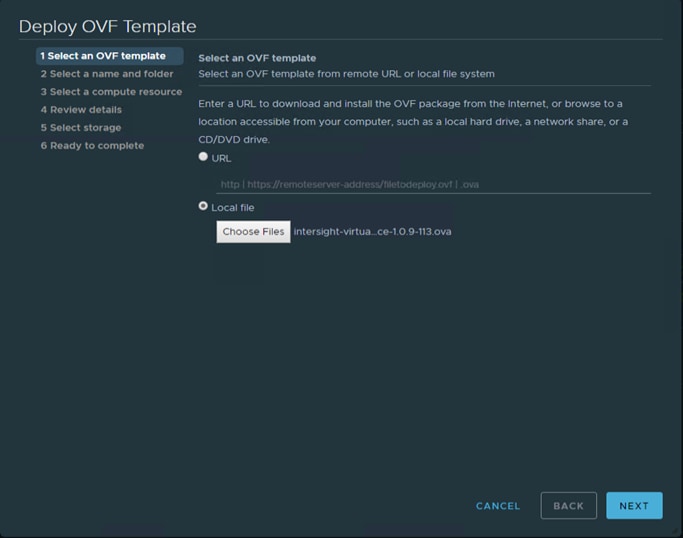
4. On the OVF Template Details page, verify the OVF template details and click Next. No input is necessary.
5. On the Select a name and location page, add/edit the Name and Location for the Virtual appliance, and click Next.
6. On the Select a resource page, select the specific Host (ESX station), Cluster, Resource Pool, or virtual appliance you want to deploy and click Next.
7. Each VM must be assigned to a specific host on clusters that are configured with vSphere HA or Manual mode vSphere DRS.
8. On the Review details page, verify the OVA template details and click Next.
Figure 22. Review Details
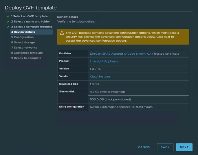
9. On the Configuration page, select a deployment configuration and click Next. You can select Small or Medium deployment configuration based on your requirement for Intersight Virtual Appliance. A brief description of the selected size displays. You can select Tiny(8 vCPU, 16 Gi RAM) deployment configuration for Intersight Assist only.
Figure 23. Select Configuration
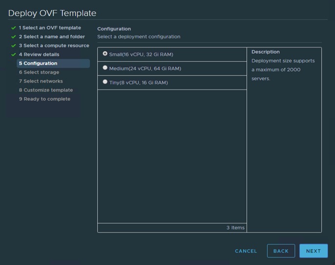
10. On the Select storage page, select a destination storage (hard drives) for the VM files in the selected host (ESX station) and click Next. Select the Disk Format for the virtual machine virtual disks. Select Thin Provision to optimize disk usage.
Figure 24. Select Storage
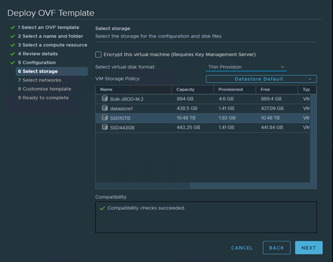
11. On the Select networks page, for each network that is specified in the OVF template, select a source network, and map it to a destination network and click Next.
Figure 25. Select Network
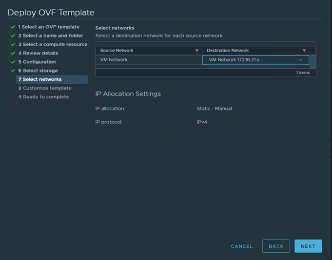
12. On the Customize Template page, customize the deployment properties of the OVF template, and click Next.
Figure 26. OVF Template Summary
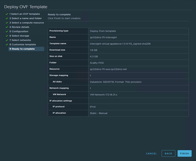
13. After finishing the deployment, power on the virtual machine.
Log into Intersight Virtual Appliance
After installing the Intersight Virtual Appliance OVA, you can connect to the configured IP address or DNS name. To log into the Intersight Virtual Appliance, follow these steps:
1. Select the installation “Intersight Connected Virtual Appliance.”
Figure 27. Select Installation
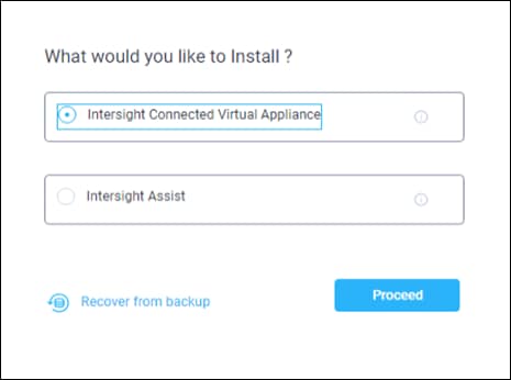
2. After you install the Cisco Intersight Virtual Appliance OVA, go to <<http://your fqdn.com>>. The Initial Setup Wizard appears and allows you to complete the setup for one of the following:
● Intersight Connected Virtual Appliance
● Intersight Assist—For more information, see the Cisco Intersight Assist documentation.
3. Select Intersight Connected Virtual Appliance and click Proceed.
The wizard runs through a series of steps to download and install software packages. You can view the progress of the installation. You can expect this process to complete in about an hour’s time. After that the formal setup is finished and you’re getting redirected to the login page where you have to change the password.
Figure 28. Connect to Intersight for the first time
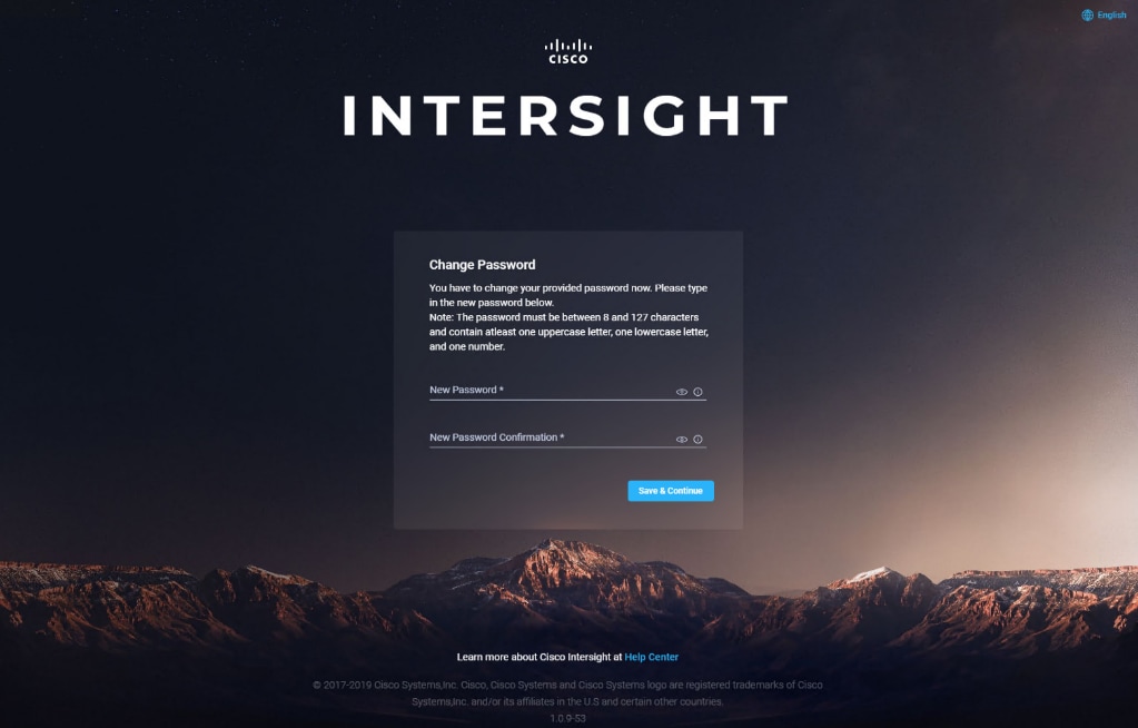
The initial Setup Wizard displays. The wizard enables you to complete the setup of the Intersight appliance.
Figure 29. Intersight Setup Wizard
To complete the setup, follow these steps:
1. Data Collection—Specify your preference to allow Intersight to send additional system information to Cisco. This option is enabled by default. For more information about what data is collected by Intersight, see Data Collected from Intersight Virtual Appliance.
Figure 30. Intersight Setup Wizard – Data Collection
2. Register License—Click Register License. Obtain a license registration token from Cisco Smart License Manager and apply add the token to activate your license. The license registration process could take a few minutes to complete. For more information about registering your Intersight license, watch Activating Intersight License.
Figure 31. Intersight Register License
3. Click Finish. The Cisco Intersight Virtual Appliance dashboard displays.
Cisco Intersight Virtual Appliance Settings
Before you start building the solution, you need configure the virtual appliance for using the correct license and for performing backups.
You need to use the right license to automatically install an operating system. You need at a minimum, the Advantage license. In our solution we used the Premier license. To change to Premier license, follow these steps:
1. Click Settings/Licensing and then click Set Default Tier.
2. Select Premier and click Set.
Figure 32. Set Intersight License
Back Up Data
Backing up the Cisco Intersight Virtual Appliance regularly is essential. Without regular backups, there is no automatic way to reconstruct the configuration settings and recreating the profiles and policies. You can perform a regular backup once a day using a scheduled backup or create backup on demand if there is a data loss or corruption event. Cisco Intersight Virtual Appliance enables you to take a full state backup of the data in the appliance and store it in a remote server. If there is a total site failure or other disaster recovery scenarios, the restore capability enables you to do a full state system restore from the backed-up system data.
Schedule Backup enables you to schedule a periodic backup of the data in the Intersight Appliance. The Appliance can store three copies of the backup locally on the appliance.
To schedule a backup, follow these steps:
1. Log in to Cisco Intersight Virtual Appliance as a user with account administrator role.
2. From the Appliance UI, navigate to Settings icon > Settings > General > Backup, click Schedule Backup.
3. On the Schedule Backup window, toggle ON Use Backup Schedule.
![]() If you disable this option, you must enable the Use Backup Schedule option to schedule a backup.
If you disable this option, you must enable the Use Backup Schedule option to schedule a backup.
4. Provide the following details to complete creating the Backup Schedule:
a. Backup Schedule
b. Day of Week—Specify the day in the week when you want to schedule a data backup.
c. Time of Day—Specify the time in the selected day when you want to schedule a data backup. The Time of Day follows the browser time of your session and displays your local time of the day.
d. Backup Destination
e. Protocol—Communication protocol (SCP/ STFP) used in the backup process.
f. Remote Port—Remote TCP port on the backup server.
g. Remote Host—The remote host for saving the backup files.
h. Remote Path—Directory location where the backup files are saved.
i. Filename—Name of the backup file to restore
j. Username—Username for authenticating the backup client to the backup server.
k. Password—Password for authenticating the backup client to the backup server.
l. Password Confirmation—Reenter the password and click Schedule Backup to complete the process.
Figure 33. Schedule Backup Configuration
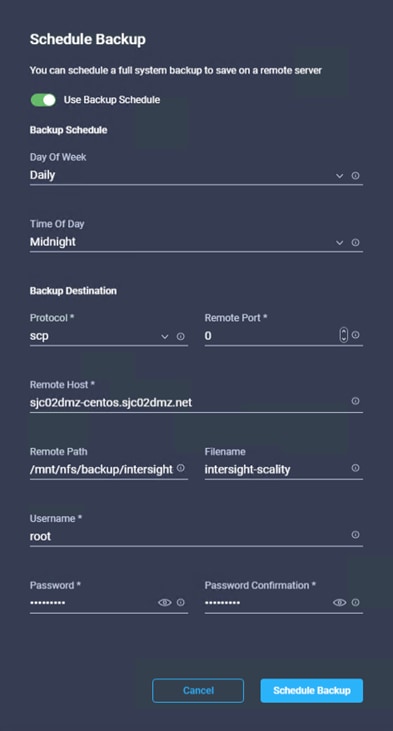
You can claim a device in Cisco Intersight Virtual Appliance through the embedded device connector. Before you claim a device, ensure that the device connector requirements are met. The following table lists the software compatibility and the supported device connector versions for Intersight Virtual Appliance:
Table 10. Device Connector Requirements
| Component |
Minimum Software Version |
Supported Device Connector Version |
Versions which include supported Device Connectors |
| Cisco UCS Manager |
3.2(1) |
1.0.9-2290 |
4.0(2a) or later |
| Cisco IMC Software |
For M5 Servers: 3.1(3a) For M4 Servers: 3.0(4) |
1.0.9-335 |
4.0(2d) or later |
| HyperFlex Connect and Data Platform |
2.6 |
1.0.9-1335 |
3.5(2a) or later |
| Cisco UCS Director |
6.7.2.0 |
1.0.9-911 |
6.7.2.0 |
To claim a device, follow these steps:
1. Log into the appliance as a user with account administrator privileges.
2. Ensure that you have completed the Cisco Intersight Virtual Appliance OVA installation and set up the appliance.
3. You have an account on the device being claimed that has administrative privileges.
4. You can claim a device or multiple devices in bulk.
5. From Intersight Dashboard > Devices, click Claim a New Device.
6. Select Multiple by File to claim multiple devices using a file.
7. Create a .csv file with the following configuration:
IMC,172.16.16.31,admin,<your_password>
IMC,172.16.16.32,admin,<your_password>
IMC,172.16.16.33,admin,<your_password>
Figure 34. Claim multiple Devices by file
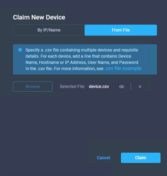
8. Click Claim and wait for a couple of minutes to get the devices connected with Cisco Intersight.
9. Click Servers to view the discovered UCS servers.
Figure 35. Claimed Devices under Servers
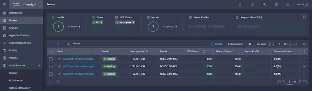
Create a Terraform Configuration Environment for Cisco Intersight
You need to prepare the environment prior to starting the automated configuration:
● Install Terraform
● Clone Repository
● Copy Terraform provider binary file
● Generate API keys
● Define Cisco Intersight Provider
● Configure Variables
You will install Terraform on an administration host; in our solution we used a virtual Linux CentOS machine. HashiCorp distributes Terraform as a binary package. You can also install Terraform using popular package managers.
To install Terraform, follow these steps:
1. Obtain the appropriate package for your system and download it as a zip archive.
2. After downloading Terraform, unzip the package. Terraform runs as a single binary named terraform. Any other files in the package can be safely removed and Terraform will still function. (You can also compile the Terraform binary from source.)
3. Make sure that the terraform binary is available on your PATH. This process will differ depending on your operating system.
[root@sjc02dmz-f11-terraform ~]# ll
total 16448
-rw-------. 1 root root 1812 Jun 15 10:49 anaconda-ks.cfg
-rw-r--r--. 1 root root 34869112 Jun 16 06:23 terraform_0.13.2_linux_amd64.zip
[root@sjc02dmz-f11-terraform ~]# unzip terraform_0.13.2_linux_amd64.zip
Archive: terraform_0.13.2_linux_amd64.zip
inflating: terraform
[root@sjc02dmz-f11-terraform ~]# ll
total 68080
-rw-------. 1 root root 1812 Jun 15 10:49 anaconda-ks.cfg
-rwxr-xr-x. 1 root root 85545348 May 27 09:38 terraform
-rw-r--r--. 1 root root 34869112 Jun 16 06:23 terraform_0.13.2_linux_amd64.zip
4. Move the terraform binary to one of the listed locations. The following command assumes that the binary is currently in your downloads folder and that your PATH includes /usr/local/bin, but you can customize it if your locations are different.
[root@sjc02dmz-f11-terraform ~]# echo $PATH
/usr/local/sbin:/usr/local/bin:/usr/sbin:/usr/bin:/root/bin
[root@sjc02dmz-f11-terraform ~]# mv ~/terraform /usr/local/bin/terraform
5. Verify the installation:
[root@sjc02dmz-f11-terraform ~]# terraform -version
Terraform v0.13.2
There is an existing Terraform Repository with examples for scale-out storage under Github.
To Clone the repository into a directory on your administration host, run the following:
[root@sjc02dmz-f11-terraform ~]# git clone https://github.com/ucs-compute-solutions/terraform-intersight-sds
Cloning into 'terraform-intersight-sds'...
remote: Enumerating objects: 59, done.
remote: Counting objects: 100% (59/59), done.
remote: Compressing objects: 100% (57/57), done.
remote: Total 59 (delta 29), reused 15 (delta 2), pack-reused 0
Unpacking objects: 100% (59/59), done.
You should now have a directory ~/terraform-intersight-sds with subdirectories for create_infra, firmware_update, os_deployment, provision_infra, and unbind_profiles.
For an overview there a subdirectory created for each task, but you can also put the files into just one directory and edit it from there.
Download and Copy Terraform Provider for Cisco Intersight
The provider block configures the named provider, in our case Cisco Intersight, which is responsible for creating and managing resources. A provider is a plugin that Terraform uses to translate the API interactions with the service. A provider is responsible for understanding API interactions and exposing resources. Because Terraform can interact with any API, you can represent almost any infrastructure type as a resource in Terraform.
To download and install the Terraform Provider for Cisco Intersight, follow these steps:
1. Download Go distribution for Linux from https://dl.google.com/go/go1.14.4.linux-amd64.tar.gz
2. Install Go on the Terraform admin host.
3. Develop the Terraform Provider for Cisco Intersight and copy it to the subdirectories:
[root@sjc02dmz-f11-terraform ~]# ll
total 204764
-rw-------. 1 root root 1812 Jun 15 10:49 anaconda-ks.cfg
drwxr-xr-x. 4 root root 28 Jun 23 08:10 go
-rw-r--r--. 1 root root 123711003 Jun 16 07:00 go1.14.4.linux-amd64.tar.gz
drwxr-xr-x. 12 root root 4096 Jun 17 06:00 intersight-python
drwxr-xr-x. 8 root root 208 Jun 17 06:14 terraform-intersight-sds
root@sjc02dmz-f11-terraform ~]# tar -C /usr/local -xzf go1.14.4.linux-amd64.tar.gz
root@sjc02dmz-f11-terraform ~]# export PATH=$PATH:/usr/local/go/bin
root@sjc02dmz-f11-terraform ~]# dnf -y install make gcc
root@sjc02dmz-f11-terraform ~]# mkdir -p /usr/local/go/bin/src/github.com/cisco-intersight/; cd /usr/local/go/bin/src/github.com/cisco-intersight/
[root@sjc02dmz-f11-terraform cisco-intersight]# git clone https://github.com/cisco-intersight/terraform-provider-intersight
[root@sjc02dmz-f11-terraform cisco-intersight]# cd terraform-provider-intersight/
[root@sjc02dmz-f11-terraform cisco-intersight]# make
[root@sjc02dmz-f11-terraform cisco-intersight]# mkdir -p ~/.terraform.d/plugins/registry.terraform.io/sjc02dmz-f11-terraform/intersight/0.1.3/linux_amd64
[root@sjc02dmz-f11-terraform cisco-intersight]# cp .build/linux_amd64/terraform-provider-intersight_v0.1.3 ~/.terraform.d/plugins/registry.terraform.io/sjc02dmz-f11-terraform/intersight/0.1.3/linux_amd64
You should now have the Terraform provider file for Cisco Intersight installed.
To start using the provider the API Key, Secret Key, and Intersight endpoint URL are required. To generate the API Keys, follow these steps:
1. Log into your Cisco Intersight virtual Appliance.
2. Go to Settings, API Keys and click on Generate API Keys.
3. Enter a description and click Generate.
Figure 36. Generate API Key
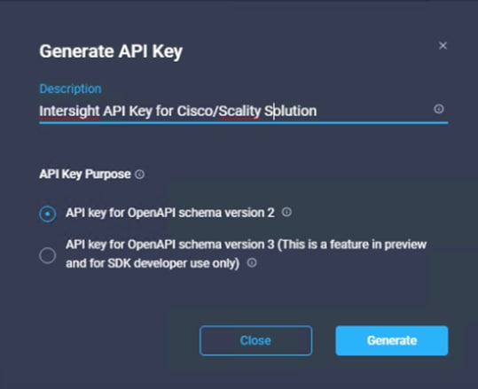
4. Copy the API Key.
5. Save the secret key into a .pem file on your Terraform administration host in the repository directory.
Define Cisco Intersight Provider
To define the Cisco Intersight Provider, follow these steps:
1. On the Terraform administration host, go into the subdirectory create_infra of the repository and edit the main.tf file:
terraform {
required_providers {
intersight = {
source = "sjc02dmz-f11-terraform/intersight"
version = "0.1.3"
}
}
}
provider "intersight" {
apikey = "5ee7b6527564612d3026f971/5ee7bff47564612d3027318a/5ee8e4b27564612d302d414c"
secretkeyfile = "/root/terraform-intersight-sds/intersight.pem"
endpoint = "sjc02dmz-f11-intersight.sjc02dmz.net"
}
2. Copy main.tf file into each other subdirectory of your repository:
[root@sjc02dmz-f11-terraform terraform-intersight-sds]# for dest in ./firmware_update/ ./os_deployment/ ./provision_infra/ ./u
nbind_profiles/ ; do \cp -f -v "/root/terraform-intersight-sds/create_infra/main.tf" "$dest" ; done
'/root/terraform-intersight-sds/create_infra/main.tf' -> './firmware_update/main.tf'
'/root/terraform-intersight-sds/create_infra/main.tf' -> './os_deployment/main.tf'
'/root/terraform-intersight-sds/create_infra/main.tf' -> './provision_infra/main.tf'
'/root/terraform-intersight-sds/create_infra/main.tf' -> './unbind_profiles/main.tf'
To provision the infrastructure, you’ll need to define variables for various workflows. These variables are:
● VLANs
● Remote server hosting images
● Remote server share
● Remote server OS image
● Remote server HUU image
● Remote server SCU image
● Remote server protocol
● Manages object ID for all nodes that needs to be provisioned
● Managed object ID for organization
Download the images for OS, HUU, and SCU from Red Hat and Cisco and store them in a directory on the Terraform server:
[root@sjc02dmz-f11-terraform create_infra]# ll /var/www/html/images/
total 6382396
-rw-r--r--. 1 root root 4550819840 Jun 16 11:38 rhel-server-7.8-x86_64-dvd.iso
-rw-r--r--. 1 root root 587167744 May 5 04:55 ucs-c240m5-huu-4.1.1f.iso
-rw-r--r--. 1 root root 1397583872 Jun 16 10:56 ucs-cxxx-scu-6.1.1b.iso
To get the managed object ID for the organization and servers, follow these steps:
1. Log into Intersight virtual appliance.
2. Click Help and then Get More Help on Cisco Intersight.
3. Click API Documentation.
4. Click API Reference.
5. Search for compute/PhysicalSummary.
6. Click GET Read a ‘compute.PhysicalSummary’ resource.
Figure 37. API Reference for compute.PhysicalSummary
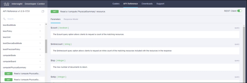
7. Change the top URL now from https://intersight.com/apidocs/compute/PhysicalSummaries/get/ to https://<your appliance FQDN>/apidocs/compute/PhysicalSummaries/get/ to the address of the virtual Intersight appliance. For example, https://sjc02dmz-f11-intersight.sjc02dmz.net/apidocs/compute/PhysicalSummaries/get/
8. Click Send.
Figure 38. GET Request from virtual Appliance
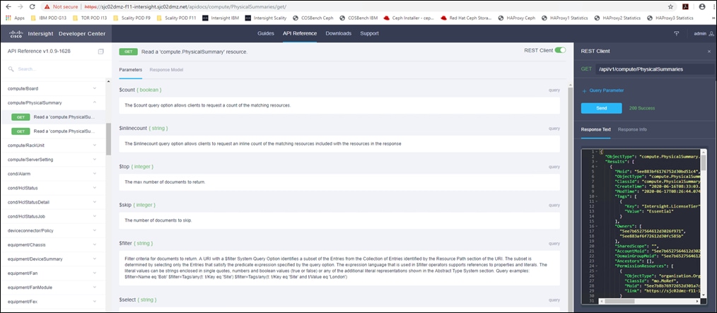
9. From the Response Text take note of the Moid of each server and the organization:
{
"Moid": "5ee883bf6176752d30bd51c4", <- Moid for server1
"ObjectType": "compute.PhysicalSummary",
.
.
"ObjectType": "organization.Organization",
"ClassId": "mo.MoRef",
"Moid": "5ee7b8b76972652d301a7ca4", <- Moid for organization
.
.
"Ipv4Address": "172.16.16.31",
"KvmIpAddresses": [
.
.
}
},
{
"Moid": "5ee883c06176752d30bd51d8", <- Moid for server2
"ObjectType": "compute.PhysicalSummary",
.
.
"Ipv4Address": "172.16.16.32",
"KvmIpAddresses": [
.
.
}
},
{
"Moid": "5ee883c26176752d30bd51fd", <- Moid for server3
"ObjectType": "compute.PhysicalSummary",
.
.
"Ipv4Address": "172.16.16.32",
"KvmIpAddresses": [
.
.
}
}
]
10. Edit the file variables.tf under create_infra as follows:
//Define all the basic variables here
variable "org_moid" {
default = "5ee7b8b76972652d301a7ca4"
}
variable "client_vlan" {
default = 205
}
variable "storage_vlan" {
default = 206
}
variable "storage-node1" {
default = "5ee883bf6176752d30bd51c4"
}
variable "storage-node2" {
default = "5ee883c06176752d30bd51d8"
}
variable "storage-node3" {
default = "5ee883c26176752d30bd51fd"
}
variable "remote-server" {
default = "172.16.21.14"
}
variable "remote-share" {
default = "/images"
}
variable "remote-os-image-storage-node1" {
default = "rhel7.8-storage-node1.iso"
}
variable "remote-os-image-storage-node2" {
default = "rhel7.8-storage-node2.iso"
}
variable "remote-os-image-storage-node3" {
default = "rhel7.8-storage-node3.iso"
}
variable "remote-scu-image" {
default = "ucs-cxxx-scu-6.1.1b.iso"
}
variable "remote-protocol" {
default = "softwarerepository.HttpServer"
}
variable "remote-huu" {
default = "ucs-c240m5-huu-4.1.1f.iso"
}
11. Copy the file to all subdirectories in the Terraform repository:
[root@sjc02dmz-f11-terraform terraform-intersight-sds]# for dest in ./firmware_update/ ./os_deployment/ ./provision_infra/ ./u
nbind_profiles/ ; do \cp -f -v "/root/terraform-intersight-sds/create_infra/variables.tf" "$dest" ; done
'/root/terraform-intersight-sds/create_infra/variables.tf' -> './firmware_update/variables.tf'
'/root/terraform-intersight-sds/create_infra/variables.tf' -> './os_deployment/variables.tf'
'/root/terraform-intersight-sds/create_infra/variables.tf' -> './provision_infra/variables.tf'
'/root/terraform-intersight-sds/create_infra/variables.tf' -> './unbind_profiles/variables.tf'
Understand Cisco Intersight Provider and Terraform Configuration
To understand and create the main configuration file, the following is an example code snippet for creating a specific vNIC from the infrastructure file:
resource "intersight_vnic_eth_if" "eth0" { -> Define the resource. In this case intersight_vnic_eth_if from https://github.com/cisco-intersight/terraform-provider-intersight/blob/master/website/docs/d/vnic_eth_if.html.markdown
name = "eth0"
order = 0
placement { -> Define the placement of the vNIC
id = "1"
pci_link = 0
uplink = 0
}
cdn {
nr_source = "vnic"
}
vmq_settings {
enabled = false
}
lan_connectivity_policy { -> Define LAN Connectivity Policy to use
moid = intersight_vnic_lan_connectivity_policy.scality-lan-connectivity-policy.id
object_type = "vnic.LanConnectivityPolicy"
}
eth_network_policy { -> Define the Network Policy to use
moid = intersight_vnic_eth_network_policy.scality-client-network.id
}
eth_adapter_policy { -> Define the Adapter Policy to use
moid = intersight_vnic_eth_adapter_policy.scality-ethernet-adapter-policy.id
}
eth_qos_policy { -> Define the QoS Policy to use
moid = intersight_vnic_eth_qos_policy.sscality-ethernet-qos-policy.id
}
}
Each resource is assigned a name, which can later be used for tracking and referencing. This name will not be reflected anywhere in the Cisco Intersight platform. It is only for reference among the .tf files. A resource can point to or reference another resource using the format <resource>.<resource_name>.<property_name>
Documentation about provider resources and configuration options can be found at https://github.com/ciscointersight/terraform-provider-intersight/tree/master/website/docs.
The Appendix contains all the configuration files for the specific sub tasks Firmware Update, OS Installation, Policies Creation, Infrastructure Provisioning, and Unbinding Profiles for reference.
Implement Terraform Configuration – Init, Plan, Apply
After creating all the configuration files and the main infrastructure files, the next step is to validate and deploy the configuration.
terraform init
The terraform init command is used to initialize a working directory containing Terraform configuration files. This is the first command that should be run after writing a new Terraform configuration or cloning an existing one from version control. It is safe to run this command multiple times.
This command performs several different initialization steps in order to prepare a working directory for use. This command is always safe to run multiple times, to bring the working directory up to date with changes in the configuration. Though subsequent runs may give errors, this command will never delete the existing configuration or state. If no arguments are given, the configuration in the current working directory is initialized.
terraform plan
The terraform plan command is used to create an execution plan. Terraform performs a refresh, unless explicitly disabled, and then determines what actions are necessary to achieve the desired state specified in the configuration files.
This command is a convenient way to check whether the execution plan for a set of changes matches the expectations without making any changes to real resources or to the state. For example, terraform plan might be run before committing a change to version control, to create confidence that it will behave as expected.
In the output, the symbols show you the following:
● Resources with a plus sign (+) will be created.
● Resources with a minus sign (-) will be deleted.
● Resources with a tilde (~) will be modified in place.
The terraform apply command is used to apply the changes required to reach the desired state of the configuration, or the pre-determined set of actions generated by a terraform plan execution plan.
Configure Scality RING Infrastructure with Terraform
The configuration to automatically prepare the environment for the following Scality RING installation consists of four steps. All of these steps were run in sub-directories for a better overview. They can also run in just one configuration file and one directory.
1. Update firmware in directory ./firmware_update
2. Create policies in directory ./create_infra
3. Provision profiles in directory ./provision_infra
4. Install OS in directory ./os_deployment
In addition to the four steps, we also implemented a task to unbind the infrastructure in the directory ./unbind_profiles.
Update Cisco UCS Firmware with Terraform
In this solution, we wanted to make sure that the Scality storage nodes were running the latest supported firmware at the time of testing. This was release Cisco HUU 4.1(1f) for Cisco UCS C240 M5L. There are various options to update the firmware. In our case we use the Terraform administration server where all the images are located under /var/www/html/images and are accessible via http. You can also pull the image via NFS or CIFS. The complete task can be found in the Appendix.
To update the Cisco UCS firmware, follow these steps:
1. Log into the Terraform administration host and run the following for updating the firmware on storage-node1:
[root@sjc02dmz-f11-terraform ~]# cd terraform-intersight-sds/firmware_update/
[root@sjc02dmz-f11-terraform firmware_update]# terraform init
Initializing the backend...
Initializing provider plugins...
- Finding sjc02dmz-f11-terraform/intersight versions matching "0.1.3"...
- Installing sjc02dmz-f11-terraform/intersight v0.1.3...
- Installed sjc02dmz-f11-terraform/intersight v0.1.3 (unauthenticated)
Terraform has been successfully initialized!
You may now begin working with Terraform. Try running "terraform plan" to see
any changes that are required for your infrastructure. All Terraform commands
should now work.
If you ever set or change modules or backend configuration for Terraform,
rerun this command to reinitialize your working directory. If you forget, other
commands will detect it and remind you to do so if necessary.
[root@sjc02dmz-f11-terraform firmware_update]# terraform plan
… -> We skip the full output as it is very lengthy.
Plan: 1 to add, 0 to change, 0 to destroy.
[root@sjc02dmz-f11-terraform firmware_update]# terraform apply
…
Plan: 1 to add, 0 to change, 0 to destroy.
Do you want to perform these actions?
Terraform will perform the actions described above.
Only 'yes' will be accepted to approve.
Enter a value: yes
intersight_firmware_upgrade.scality-firmware-update: Creating...
intersight_firmware_upgrade.scality-firmware-update: Creation complete after 0s [id=5ef333307068612d306032c7]
Apply complete! Resources: 1 added, 0 changed, 0 destroyed.
2. Change the firmware_update.tf file and insert storage-node2 under server:
server {
object_type = "compute.RackUnit"
moid = var.storage-node2
}
3. Repeat these steps with storage-node3.
Prepare Custom RHEL ISO Images for Automated Installation
The last part of the Cisco UCS automation is the installation of RHEL 7.8 on all Scality storage nodes through Terraform. As a goal we want to have three individual installations, each for every single storage node. For that we create custom ISO files, which include a kickstart file with all the specific details for the storage node. An example kickstart file for storage node 1 is provided below:
lang en_US.UTF-8
keyboard --vckeymap=us --xlayouts='us'
timezone --isUtc America/Los_Angeles --ntpservers=173.38.201.115
# System services
services --enabled="chronyd"
rootpw $1$pm1n5WC0$AD5clDkZR/vCZTIIIbUa11 --iscrypted
#platform x86, AMD64, or Intel EM64T
cdrom
reboot
#Network Information
network --bootproto=static --device=bond0 --ip=172.16.21.21 --netmask=255.255.255.0 --gateway=172.16.21.1 --hostname=sjc02dmz-f11-storage1.sjc02dmz.net --nameserver=192.168.10.51 --noipv6 --mtu=9000 --onboot=on --activate --bondopts=mode=802.3ad,miimon=100,xmit_hash_policy=layer3+4,lacp_rate=1 --bondslaves=eth0,eth1
network --bootproto=static --device=bond1 --ip=172.16.22.21 --netmask=255.255.255.0 --noipv6 --mtu=9000 --onboot=on --activate --bondopts=mode=802.3ad,miimon=100,xmit_hash_policy=layer3+4,lacp_rate=1 --bondslaves=eth2,eth3
bootloader --location=mbr --append="rhgb quiet crashkernel=auto" --boot-drive=/dev/disk/by-path/pci-0000:18:00.0-scsi-0:2:0:0
clearpart --all --initlabel
zerombr
# Disk partitioning information
part pv.1 --fstype="lvmpv" --ondisk=/dev/disk/by-path/pci-0000:18:00.0-scsi-0:2:0:0 --size=890000
part /boot --fstype="xfs" --ondisk=/dev/disk/by-path/pci-0000:18:00.0-scsi-0:2:0:0 --size=1024
volgroup scality --pesize=4096 pv.1
logvol /home --fstype="xfs" --size=10240 --name=home --vgname=scality
logvol swap --fstype="swap" --size=4096 --name=swap --vgname=scality
logvol / --fstype="xfs" --size=51200 --name=root --vgname=scality
logvol /var --fstype="xfs" --grow --size=1 --name=var --vgname=scality
logvol /tmp --fstype="xfs" --size=20480 --name=tmp --vgname=scality
auth --passalgo=sha512 --useshadow
selinux --disabled
firewall --disabled
firstboot --disable
ignoredisk --only-use=/dev/disk/by-path/pci-0000:18:00.0-scsi-0:2:0:0
%packages
@^minimal
@core
chrony
kexec-tools
%end
%addon com_redhat_kdump --enable --reserve-mb='auto'
%end
To create a custom ISO for RHEL 7.8, follow these steps:
1. Mount the DVD ISO:
[root@sjc02dmz-f11-terraform ~]# mount -o loop /var/www/html/images/rhel-server-7.8-x86_64-dvd.iso /mnt
mount: /mnt: WARNING: device write-protected, mounted read-only.
2. Create a directory and copy all the content of the ISO into the same.
[root@sjc02dmz-f11-terraform ~]# shopt -s dotglob
[root@sjc02dmz-f11-terraform ~]# mkdir /tmp/rhel7
[root@sjc02dmz-f11-terraform ~]# cp -avRf /mnt/* /tmp/rhel7
3. Verify that all hidden files like .treeinfo are there in /tmp/rhel7
[root@sjc02dmz-f11-terraform ~]# cd /tmp/rhel7
[root@sjc02dmz-f11-terraform rhel7]# ls -a
. addons EFI extra_files.json images LiveOS Packages RPM-GPG-KEY-redhat-beta TRANS.TBL
.. .discinfo EULA GPL isolinux media.repo repodata RPM-GPG-KEY-redhat-release .treeinfo
4. Get the kickstart file and copy it to /tmp/rhel7
[root@sjc02dmz-f11-terraform rhel7]# cp /var/www/html/images/ks1.cfg /tmp/rhel7/
5. Confirm the LABEL of the DVD iso. This will give the LABEL information.
[root@sjc02dmz-f11-terraform rhel7]# blkid /var/www/html/images/rhel-server-7.8-x86_64-dvd.iso
/var/www/html/images/rhel-server-7.8-x86_64-dvd.iso: UUID="2020-02-25-11-40-31-00" LABEL="RHEL-7.8 Server.x86_64" TYPE="iso9660" PTUUID="13fb291d" PTTYPE="dos"
6. Add the following part in /tmp/rhel7/isolinux/isolinux.cfg file as follows. Make sure that the part has inst.stage2 and the correct label. Remove “menu default” from “label check” and change timeout to 100.
label kickstart
menu label ^Kickstart Installation of RHEL7.8
kernel vmlinuz
menu default
append initrd=initrd.img inst.stage2=hd:LABEL=RHEL-7.8\x20Server.x86_64 inst.ks=cdrom:/ks1.cfg net.ifnames=0 biosdevname=0
7. Now, save the file and create the ISO as follows. Make sure that -V has the correct LABEL , a slight mistake in that will make DVD not working.
[root@sjc02dmz-f11-terraform rhel7]# mkisofs -o /tmp/rhel7.8-storage-node1.iso -b isolinux/isolinux.bin -J -R -l -c isolinux/boot.cat -no-emul-boot -boot-load-size 4 -boot-info-table -eltorito-alt-boot -e images/efiboot.img -no-emul-boot -graft-points -V "RHEL-7.8 Server.x86_64" .
[root@sjc02dmz-f11-terraform rhel7]# cp ../rhel7.8-storage-node1.iso /var/www/html/images/
8. Repeat steps 1-7 for storage-node2 and storage-node3 with the different kickstart file and copy them to /var/www/html/images.
Create Cisco Intersight Policies and Profiles with Terraform
After upgrading the firmware to the latest Cisco HUU release, we start creating the policies we need for the Scality RING solution and build the server profiles out of the policies. The full configuration file is in the Appendix. The following policies will be built by Terraform:
Table 11. Terraform Provider Policies and Resource Objects
| Policy |
Terraform Resource Object |
Comments |
| Adapter Configuration |
intersight_adapter_config_policy |
Specify the PCI slot ID where the Cisco VIC adapter is placed and set FEC mode for 25G connectivity Configured: ● Slot 1 ● FEC mode cl74 |
| Ethernet Adapter |
intersight_vnic_eth_adapter_policy |
Specify the adapter properties to improve the throughput over network Configured: ● Interrupt 32 ● Completion 16 ● Rx count 8 and ring size 4096 ● Tx count 8 and ring size 4096 ● RSS true |
| Ethernet Network |
intersight_vnic_eth_network_policy |
Specify the network and VLANs used for Scality RING, in our cases two networks with different VLANs Configured: ● Client network VLAN 205 ● Storage network VLAN 206 |
| Ethernet QoS |
intersight_vnic_eth_qos_policy |
Specify the Quality of Service with MTU size 9000 Configured: ● MTU 9000 |
| LAN Connectivity |
inter-sight_vnic_lan_connectivity_policy intersight_vnic_eth_if |
Specify the LAN connectivity with the vNICs Configured: ● eth0 (uplink port 0), eth1 (uplink port 1) for Client network ● eth2 (uplink port 0), eth3 (uplink port 1) for Storage network |
| NTP |
intersight_ntp_policy |
Specify the NTP servers to be used Configured: ● NTP IP 173.38.201.115 |
| Disk Group |
intersight_storage_disk_group_policy |
Specify the disk group policies for Boot disks (RAID 1) and Data disks (RAID 0) Configured: ● Slot 13 and 14 RAID 1 for Boot ● Slot 1-12, each disk RAID 0 for Data |
| Storage |
intersight_storage_storage_policy |
Specify the Storage Policies with the previous created disk group policies. Configured: ● Virtual disk for Boot ● Virtual disks for Data ● All in common: ReadWrite, Rea-dAhead, WriteBackGoodBBU |
| Boot Order |
intersight_boot_precision_policy |
Specify the boot order. Configured: ● Local disk from MRAID ● Virtual media from CIMC mapped DVD |
After creating the policies, the same task creates the server profiles for all three Scality storage nodes. To start building the policies and profiles, log into the Terraform administration host and follow these steps:
[root@sjc02dmz-f11-terraform ~]# cd terraform-intersight-sds/create_infra/
[root@sjc02dmz-f11-terraform create_infra]# terraform init
[root@sjc02dmz-f11-terraform create_infra]# terraform plan
… -> We skipped the full output since it is very lengthy.
Plan: 32 to add, 0 to change, 0 to destroy.
[root@sjc02dmz-f11-terraform create_infra]# terraform apply
…
Do you want to perform these actions?
Terraform will perform the actions described above.
Only 'yes' will be accepted to approve.
Enter a value: yes
intersight_storage_disk_group_policy.scality-disk-group-data12-policy: Creating...
intersight_vnic_eth_qos_policy.scality-ethernet-qos-policy: Creating...
intersight_vnic_eth_network_policy.scality-storage-network: Creating...
intersight_storage_disk_group_policy.scality-disk-group-data10-policy: Creating...
intersight_storage_disk_group_policy.scality-disk-group-data3-policy: Creating...
intersight_storage_disk_group_policy.scality-disk-group-data5-policy: Creating...
intersight_server_profile.storage-node2: Creating...
intersight_vnic_eth_adapter_policy.scality-ethernet-adapter-policy: Creating...
intersight_vnic_eth_network_policy.scality-client-network: Creating...
intersight_storage_disk_group_policy.scality-disk-group-data8-policy: Creating...
intersight_vnic_eth_adapter_policy.scality-ethernet-adapter-policy: Creation complete after 0s [id=5f61f5d81b697f129846212d]
intersight_storage_disk_group_policy.scality-disk-group-data8-policy: Creation complete after 0s [id=5f61f5d9656f6e2d3005a499]
intersight_storage_disk_group_policy.scality-disk-group-data4-policy: Creating...
intersight_storage_disk_group_policy.scality-disk-group-data2-policy: Creating...
intersight_vnic_eth_qos_policy.scality-ethernet-qos-policy: Creation complete after 0s [id=5f61f5d91b697f1298462133]
intersight_server_profile.storage-node1: Creating...
intersight_storage_disk_group_policy.scality-disk-group-data12-policy: Creation complete after 0s [id=5f61f5d9656f6e2d3005a49f]
intersight_storage_disk_group_policy.scality-disk-group-data9-policy: Creating...
intersight_vnic_eth_network_policy.scality-storage-network: Creation complete after 0s [id=5f61f5d91b697f1298462139]
intersight_storage_disk_group_policy.scality-disk-group-data6-policy: Creating...
intersight_storage_disk_group_policy.scality-disk-group-data3-policy: Creation complete after 0s [id=5f61f5d9656f6e2d3005a4a5]
intersight_storage_disk_group_policy.scality-disk-group-boot-policy: Creating...
intersight_storage_disk_group_policy.scality-disk-group-data10-policy: Creation complete after 0s [id=5f61f5d9656f6e2d3005a4ab]
intersight_server_profile.storage-node3: Creating...
intersight_vnic_eth_network_policy.scality-client-network: Creation complete after 0s [id=5f61f5d91b697f129846213f]
intersight_storage_disk_group_policy.scality-disk-group-data1-policy: Creating...
intersight_server_profile.storage-node2: Creation complete after 0s [id=5f61f5d977696e2d30df5ceb]
intersight_storage_disk_group_policy.scality-disk-group-data11-policy: Creating...
intersight_storage_disk_group_policy.scality-disk-group-data5-policy: Creation complete after 0s [id=5f61f5d9656f6e2d3005a4b1]
intersight_storage_disk_group_policy.scality-disk-group-data7-policy: Creating...
intersight_storage_disk_group_policy.scality-disk-group-data4-policy: Creation complete after 0s [id=5f61f5d9656f6e2d3005a4b8]
intersight_storage_disk_group_policy.scality-disk-group-data2-policy: Creation complete after 0s [id=5f61f5d9656f6e2d3005a4be]
intersight_vmedia_policy.scality-vmedia-policy-storage2: Creating...
intersight_storage_disk_group_policy.scality-disk-group-data9-policy: Creation complete after 0s [id=5f61f5d9656f6e2d3005a4c4]
intersight_server_profile.storage-node1: Creation complete after 0s [id=5f61f5d977696e2d30df5cf7]
intersight_storage_disk_group_policy.scality-disk-group-data6-policy: Creation complete after 0s [id=5f61f5d9656f6e2d3005a4ca]
intersight_vmedia_policy.scality-vmedia-policy-storage1: Creating...
intersight_storage_disk_group_policy.scality-disk-group-boot-policy: Creation complete after 0s [id=5f61f5d9656f6e2d3005a4d1]
intersight_server_profile.storage-node3: Creation complete after 1s [id=5f61f5d977696e2d30df5d03]
intersight_storage_disk_group_policy.scality-disk-group-data1-policy: Creation complete after 1s [id=5f61f5d9656f6e2d3005a4d7]
intersight_vnic_lan_connectivity_policy.scality-lan-connectivity-policy: Creating...
intersight_adapter_config_policy.scality-adapter-config-policy: Creating...
intersight_boot_precision_policy.scality-boot-policy: Creating...
intersight_vmedia_policy.scality-vmedia-policy-storage3: Creating...
intersight_ntp_policy.scality-ntp-policy: Creating...
intersight_storage_disk_group_policy.scality-disk-group-data11-policy: Creation complete after 1s [id=5f61f5d9656f6e2d3005a4de]
intersight_storage_disk_group_policy.scality-disk-group-data7-policy: Creation complete after 1s [id=5f61f5d9656f6e2d3005a4e4]
intersight_storage_storage_policy.scality-storage-policy: Creating...
intersight_vmedia_policy.scality-vmedia-policy-storage2: Creation complete after 1s [id=5f61f5d96275722d30881f9d]
intersight_vmedia_policy.scality-vmedia-policy-storage1: Creation complete after 1s [id=5f61f5d96275722d30881fa8]
intersight_vnic_lan_connectivity_policy.scality-lan-connectivity-policy: Creation complete after 0s [id=5f61f5d91b697f1298462151]
intersight_boot_precision_policy.scality-boot-policy: Creation complete after 0s [id=5f61f5d96275722d30881fb4]
intersight_vnic_eth_if.eth3: Creating...
intersight_adapter_config_policy.scality-adapter-config-policy: Creation complete after 0s [id=5f61f5d91b697f1298462166]
intersight_vnic_eth_if.eth1: Creating...
intersight_vmedia_policy.scality-vmedia-policy-storage3: Creation complete after 0s [id=5f61f5d96275722d30881fc8]
intersight_vnic_eth_if.eth2: Creating...
intersight_vnic_eth_if.eth0: Creating...
intersight_storage_storage_policy.scality-storage-policy: Creation complete after 0s [id=5f61f5d9656f6e2d3005a4ee]
intersight_ntp_policy.scality-ntp-policy: Creation complete after 0s [id=5f61f5d96275722d30881fde]
intersight_vnic_eth_if.eth3: Creation complete after 0s [id=5f61f5d91b697f12984621ac]
intersight_vnic_eth_if.eth1: Creation complete after 0s [id=5f61f5d91b697f12984621bd]
intersight_vnic_eth_if.eth2: Creation complete after 0s [id=5f61f5d91b697f12984621cc]
intersight_vnic_eth_if.eth0: Creation complete after 0s [id=5f61f5d91b697f12984621dc]
Apply complete! Resources: 32 added, 0 changed, 0 destroyed.
You can now view in Intersight under Policies the 25 new policies.
Figure 39. Cisco Intersight Server Policies after Terraform task
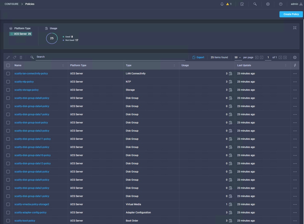
Under Profiles you can view the three new server profiles for the Scality storage nodes.
Figure 40. Cisco Intersight Server Profiles after Terraform task
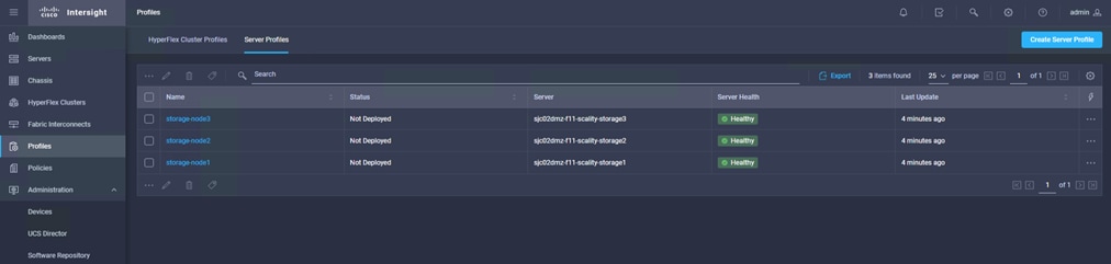
The formal task of creating policies and profiles is now finished and in the next step the server profiles get associated with the selected servers.
Associate Cisco Intersight Profiles with Terraform
In the next step, associate the former created server profiles with Terraform to the physical servers. The configuration file is located in the provision_infra directory and can be seen in the Appendix section. Log into the Terraform administration server and run the following commands:
[root@sjc02dmz-f11-terraform ~]# cd terraform-intersight-sds/provision_infra/
[root@sjc02dmz-f11-terraform ~]# terraform init
[root@sjc02dmz-f11-terraform ~]# terraform plan
… -> We skip the full output as it is very lengthy.
Plan: 3 to add, 0 to change, 0 to destroy.
------------------------------------------------------------------------
[root@sjc02dmz-f11-terraform ~]# terraform apply
…
Plan: 3 to add, 0 to change, 0 to destroy.
Do you want to perform these actions?
Terraform will perform the actions described above.
Only 'yes' will be accepted to approve.
Enter a value: yes
intersight_server_profile.storage-node3: Creating...
intersight_server_profile.storage-node1: Creating...
intersight_server_profile.storage-node2: Creating...
intersight_server_profile.storage-node1: Creation complete after 0s [id=5ef31e8877696e2d3092a777]
intersight_server_profile.storage-node2: Creation complete after 0s [id=5ef31e8877696e2d3092a76d]
intersight_server_profile.storage-node3: Creation complete after 0s [id=5ef31e8877696e2d3092a781]
Apply complete! Resources: 3 added, 0 changed, 0 destroyed.
Verify the deployment by checking the status in Cisco Intersight under Profiles.
Figure 41. Server Profile Deployment Status
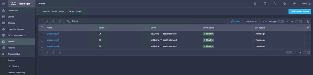
If any changes need to be done, unbind the Server Profile and then the server policies can be easily changed with the Terraform commands. To unbind the Server Profile, follow these steps:
1. Go to the subdirectory ./unbind_profiles on the Terraform administration host.
2. Edit unbind_profiles.tf with the server you want to unbind.
3. Re-run terraform apply.
4. Edit the policies in ./create_infra/infra.tf and re-run with terraform apply.
5. Then change to ./provision_infra and bind the profiles again with terraform apply.
Automated Install of RHEL OS with Terraform
After doing a firmware upgrade, creating policies and profiles, assigning, and deploying profiles, in the last steps we do an automated install of RHEL 7.8 on all Scality storage nodes. The process contains two actions:
● Create the Software Repository with the OS image for each storage node and the Server Configuration Utility for the environment.
● Trigger all storage nodes to reboot and boot via vMedia from the OS image.
For that you need two specific configuration files; repo.tf and os_install.tf. repo.tf creates the software repositories in Cisco Intersight. os_install.tf reboots the storage nodes and installs the OS based on the software repository.
To do an automated OS install with Terraform under Cisco Intersight, follow these steps:
1. Log into the Terraform server and go to subdirectory for OS install:
[root@sjc02dmz-f11-terraform ~]# cd terraform-intersight-sds/os_deployment/
2. Run terraform plan to see whether your configuration runs through:
[root@sjc02dmz-f11-terraform os_deployment]# terraform plan
… -> We skip the full output as it is very lengthy.
Plan: 7 to add, 0 to change, 0 to destroy.
------------------------------------------------------------------------
Note: You didn't specify an "-out" parameter to save this plan, so Terraform
can't guarantee that exactly these actions will be performed if
"terraform apply" is subsequently run.
3. If your configuration is good, run the apply command to deploy the OS:
[root@sjc02dmz-f11-terraform os_deployment]# terraform apply
Prepare Virtual Environment for Scality RING Solution
This section provides detailed information about deploying virtual machines for Scality RING Supervisor with RHEL 7.8 and Scality NAS Archiver virtual machines with Windows 2016.
Deployment of Scality Supervisor VM on ESXi 6.7 with Terraform
Preparation of the Environment
In the same way you deployed the Cisco UCS environment under Cisco Intersight with Terraform, you are now going to prepare the Scality RING Supervisor virtual machine with Terraform as well.
The VMware vSphere provider gives Terraform the ability to work with VMware vSphere Products, notably vCenter Server and ESXi. This provider can be used to manage many aspects of a VMware vSphere environment, including virtual machines, standard and distributed networks, datastores, and more.
In this solution you’re going to create three virtual machines with Terraform:
● Scality RING Supervisor
● Scality NAS Archiver Database
● Scality NAS Archiver Portals
Before creating all three virtual machines, you need to create a Linux boot image for the Scality RING Supervisor VM. The procedure is the same as it was described in the previous section Prepare Custom RHEL ISO Images for automated Installation. See the Appendix for the kickstart file for the Supervisor. This enables Terraform to do a fully automated install of the OS with pre-defined variables. Upload two images to a VMware ESXi server: RHEL 7.8 ISO image for the Scality Supervisor and Windows 2016 ISO image for the Scality NAS Archiver.
Upload ISO Images to vSphere Host
To upload the ISO images for Supervisor and NAS Archiver to the vSphere host, follow these steps:
1. Log into your vSphere host and click Storage.
2. Click the datastore you would like to use for the ISO image.
3. Click Datastore Browser. A new window opens.
Figure 42. Datastore Browser
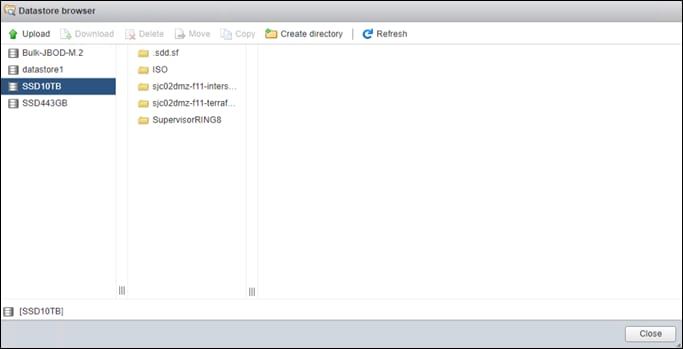
4. Click Create directory and type a name for a new directory.
5. Click the new directory and then click Upload.
6. Select the Scality RING Supervisor ISO and then Open. Repeat this for the Windows 2016 ISO for NAS Archiver.
7. Click Close.
Run Terraform to install Virtual Machines
To create a VMware vSphere provider main.tf, run the following:
provider "vsphere" {
user = "administrator@sjc02dmz.net"
password = "XXX"
vsphere_server = "192.168.10.50"
version = "~> 1.21"
allow_unverified_ssl = true
}
Next you’ll create the configuration file for all three virtual machines in a file called create_vm.tf. The Terraform file describes the details for each virtual machine. A set of global variables in the beginning defines the datacenter, datastore, a resource pool and the networks to be used. In the following example, the virtual machine for the Scality RING Supervisor is defined with all the specific details for CPU, Memory, Disk, and Network as well as the boot device:
data "vsphere_datacenter" "dc" {
name = "Scality POD" #e.g Datacenter1
}
data "vsphere_datastore" "datastore" {
name = "SSD10TB" #e.g Datastore1
datacenter_id = "${data.vsphere_datacenter.dc.id}"
}
data "vsphere_resource_pool" "pool" {
name = "Compute" #e.g "Compute Cluster/Resources"
datacenter_id = "${data.vsphere_datacenter.dc.id}"
}
data "vsphere_network" "network1" {
name = "VM Network 172.16.21.x" #e.g VM Network
datacenter_id = "${data.vsphere_datacenter.dc.id}"
}
data "vsphere_network" "network2" {
name = "VM Network 172.16.22.x" #e.g VM Network
datacenter_id = "${data.vsphere_datacenter.dc.id}"
}
resource "vsphere_virtual_machine" "vm" {
name = "SupervisorRING"
resource_pool_id = "${data.vsphere_resource_pool.pool.id}"
datastore_id = "${data.vsphere_datastore.datastore.id}"
boot_delay = 10000
wait_for_guest_net_timeout = 0
num_cpus = 4
memory = 16384
guest_id = "rhel7_64Guest"
network_interface {
network_id = "${data.vsphere_network.network1.id}"
}
network_interface {
network_id = "${data.vsphere_network.network2.id}"
}
disk {
label = "disk0"
size = 800
thin_provisioned = false
}
cdrom {
datastore_id = "${data.vsphere_datastore.datastore.id}"
path = "ISO/rhel7.8-supervisor.iso"
}
}
Next, deploy the virtual machines with Terraform:
[root@sjc02dmz-f11-terraform vmware]# terraform plan
Refreshing Terraform state in-memory prior to plan...
The refreshed state will be used to calculate this plan, but will not be
persisted to local or remote state storage.
data.vsphere_datacenter.dc: Refreshing state...
data.vsphere_datastore.datastore: Refreshing state...
data.vsphere_resource_pool.pool: Refreshing state...
data.vsphere_network.network2: Refreshing state...
data.vsphere_network.network1: Refreshing state...
… -> We skipped the full output since it is very lengthy.
Plan: 3 to add, 0 to change, 0 to destroy.
[root@sjc02dmz-f11-terraform vmware]# terraform apply
… -> We skipped the full output since it is very lengthy.
vsphere_virtual_machine.vm1: Creating...
vsphere_virtual_machine.vm: Creating...
vsphere_virtual_machine.vm2: Creating...
vsphere_virtual_machine.vm2: Creation complete after 1s [id=423c46d7-902e-69c3-6d3a-d8f54a4ee2a2]
vsphere_virtual_machine.vm1: Creation complete after 3s [id=423cf529-bbcb-077a-3c8f-369536aa9199]
vsphere_virtual_machine.vm: Creation complete after 8s [id=423c1a9d-1944-fe18-7ba6-2335abb9bc89]
Apply complete! Resources: 3 added, 0 changed, 0 destroyed.
You have now successfully deployed the Scality RING Supervisor VM. Next, you’ll prepare all Scality NAS Archiver VM with Windows 2016.
Installation of Scality NAS Archiver
Base Installation of Windows 2016
After deploying the virtual machines for NAS Archiver, the next step is to install Windows 2016 on both systems. The following procedure is for the base install of one server; repeat these steps with the other server.
![]() Currently, Terraform for vSphere Virtual Machine does not provide an integration for a USB controller. This causes a misbehavior of the mouse integration unless the VMware Tools is installed. We strongly recommend doing the installation with the keyboard and shortcuts.
Currently, Terraform for vSphere Virtual Machine does not provide an integration for a USB controller. This causes a misbehavior of the mouse integration unless the VMware Tools is installed. We strongly recommend doing the installation with the keyboard and shortcuts.
1. Log into your vSphere ESXi server and click Virtual Machines.
2. Click one of the three servers you would like to install and then Console. Click Launch remote console.
Figure 43. Virtual Machine Console
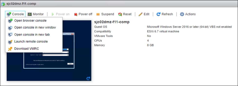
3. Use Tab to move to Next and press Enter or change Language, Time, and Keyboard according to your needs.
4. Press Enter to Install Now.
5. Click” I don’t have a product key” and press Enter or enter a product key.
Figure 44. Activate Windows
6. Select Windows Server 2016 Standard (Desktop Experience) and then click Next.
Figure 45. Select Operating System to install
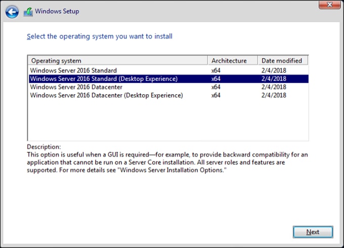
7. Accept the license terms and click Next.
8. Select Custom: Install Windows only (advanced) and then click Next.
Figure 46. Select Type of Installation
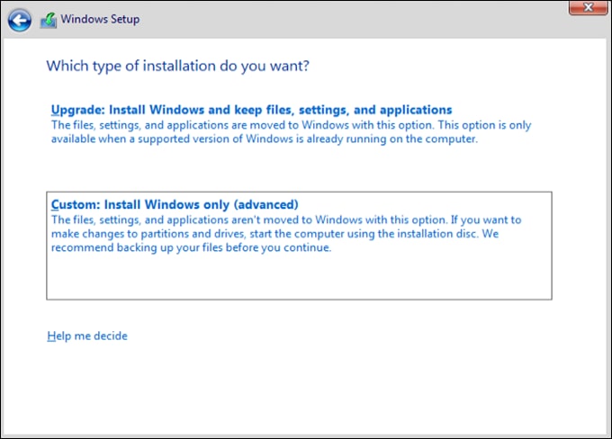
9. Click Next in the disk screen.
Figure 47. Disk Selection
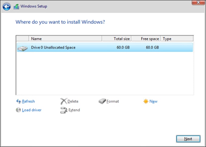
10. After the installation and the reboot, the screen for the Administrator password appears. Enter the new password for the Administrator and click Finish.
11. Click VMRC -> Send Ctrl-Alt-Delete and enter your new password.
12. The Server Manager Window appears. Click with your mouse on the window and a menu opens in the top left. Click Close.
Figure 48. Server Manager Menu
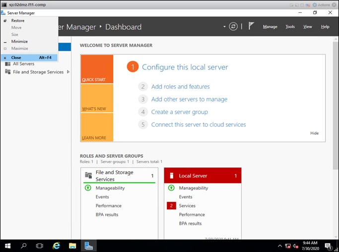
13. Click VMRC and click Manage -> Install VMware Tools.
14. Press the Tab key until you see the ‘start button’ highlighted, then press Enter, then type cmd and press Enter
15. Change the drive and run the setup command to install VMware Tools. The VM automatically reboots.
C:\Users\Administrator>d:
D:\>setup64.exe /s /v”/qn reboot=y”
16. After the reboot click VMRC -> Send Ctrl-Alt-Delete and enter your password. You now have full mouse access.
17. Click the Windows Logo, click Control Panel -> Network and Internet -> Network and Sharing Center -> Ethernet0 -> Properties and double-click Internet Protocol Version 4 (TCP/IPv4).
18. Click Use the following IP address and fill out all the necessary fields.
Figure 49. IPv4 Configuration
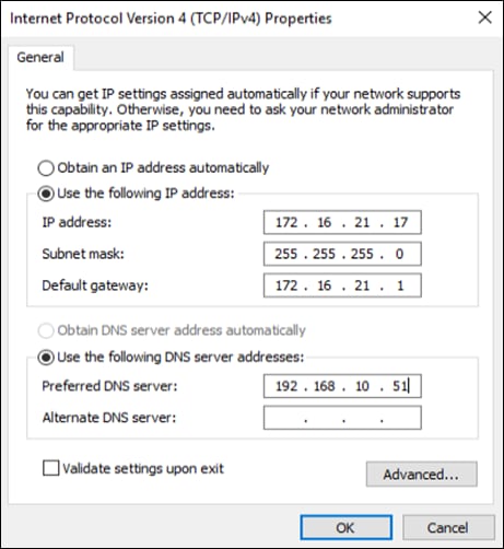
19. Click OK, then click OK, then click Yes on the blue field and then click Close.
20. In the open Network Sharing window search for domain and click Join a Domain.
21. Click Change and type in the Computer name for the system. Go to Domain and type in the domain name and click OK.
Figure 50. Computer Name/Domain Changes
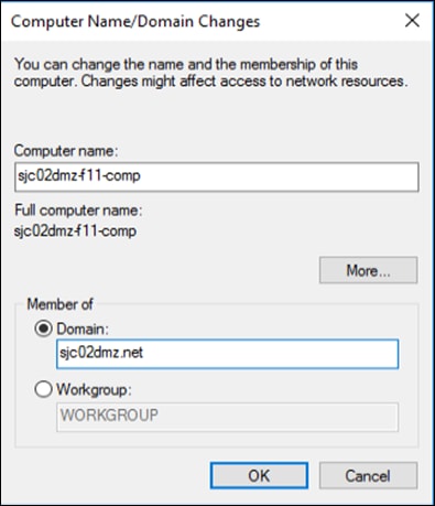
22. Ignore the NetBIOS message and log into your domain server with the specific credentials. After successful logon a Welcome message displays and a prompt to reboot the server.
23. Reboot the server and login again.
24. Go to Start -> Control Panel -> System and Security -> Remote Access.
25. Click Allow remote connections to this computer and then Select Users.
26. Click Add and type in the field the username you want to use for remote access. Click Check Names and type in the credentials of the AD server.
![]() In our environment, we used an AD Domain Controller and created a user on that server before. You can also run the environment with local users but would have more administration tasks to do. Please make sure that this user has administration rights.
In our environment, we used an AD Domain Controller and created a user on that server before. You can also run the environment with local users but would have more administration tasks to do. Please make sure that this user has administration rights.
Figure 51. Select User for Remote Access
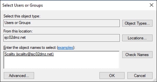
27. Click OK, then click OK again and then click Close.
28. Restart the virtual machine.
29. After the restart, log into the system and make sure that you run all Windows Updates to update the server with the latest security patches.
30. Repeat steps 1-29 for the other virtual machine with a different hostname and IP address.
Configuration Changes for NAS Archiver
To prepare the SQL and the Portal server for the NAS Archiver install, you need to make some minor configuration changes.
NAS Archiver Portal Server
For the Portal server, the IIS role needs to be installed and enabled. Additionally, two firewall ports need to be enabled to communicate to the NAS Archiver SQL host. To configure, follow these steps
1. Log into the NAS Archiver Portal server and open the Server Manager under the Windows Start Menu.
2. Click Manage -> Add Roles and Features.
3. Click Next, then click Next, and click Next again.
4. Select Web Server (IIS) and then click Add Features.
Figure 52. Server Role IIS
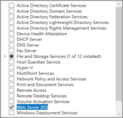
5. Click Next, then click Next, and click Next again.
6. Under Role Security select Basic Authentication and Windows Authentication only.
Figure 53. Security Role under IIS
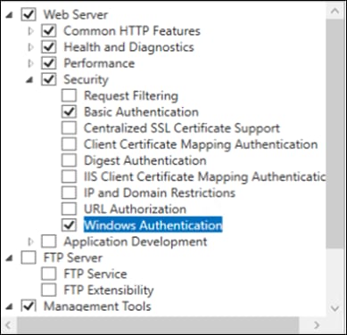
7. Under Role Application Development select .NET Extensibility 3.5 and click Add Features.
8. Select .NET Extensibility 4.6 and ASP and click Add Features.
9. Select ASP.NET 3.5 and click Add Features.
10. Select ASP.NET 4.6 and make sure that ISAPI Extensions and ISAPI Filters is selected as well.
Figure 54. Application Development Role under IIS
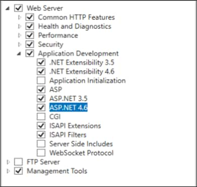
11. Click Next. Ignore the warning and click Install.
To change the firewall to allow communication from the NAS Archiver SQL host, follow these steps:
1. Click the Windows Start menu and type in “firewall”. Select “Windows Firewall with Advanced Security”.
2. Click Inbound Rules and then click New Rule.
Figure 55. Windows Firewall with Advanced Security
![]()
![]()
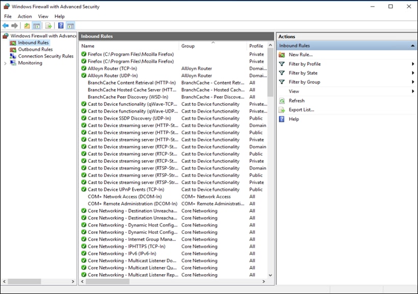
3. Click Port and then click Next.
Figure 56. Windows Firewall Rule Type

4. Select TCP, specify the ports 80 and 1433 and click Next.
Figure 57. Windows Firewall Protocols and Ports

5. Select Allow the connection and click Next.
Figure 58. Windows Firewall Action
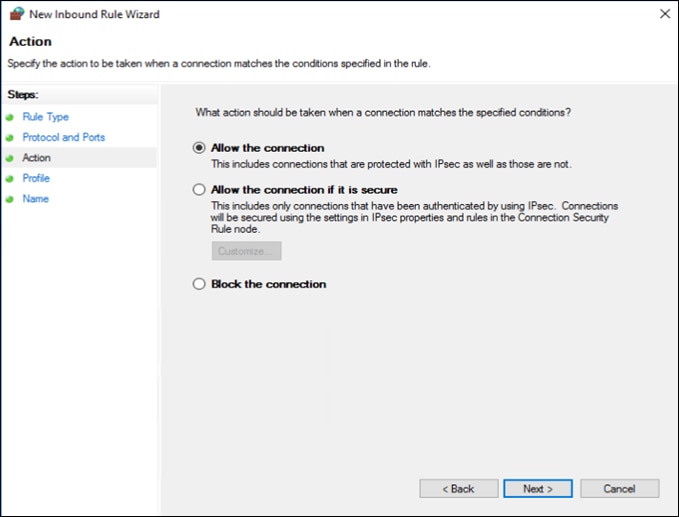
6. Under Profile select Domain and click Next.
Figure 59. Windows Firewall Profile
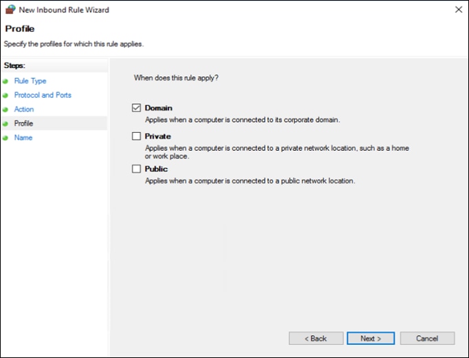
7. Type a Name and click Finish.
Figure 60. Windows Firewall Name

The Portal server is now ready for the installation.
NAS Archiver SQL Server
To install MS SQL 2016 on the NAS Archiver SQL server and change the firewall to work with the appropriate ports for the NAS Archiver, follow these steps:
1. Log into the Scality NAS Archiver SQL server and start the MS SQL installation application.
![]() We already downloaded MS SQL 2016 and uploaded it to the server.
We already downloaded MS SQL 2016 and uploaded it to the server.
2. Click Yes to allow this app to make changes to your device.
3. Select Installation on the left and then New SQL Server stand-alone installation or add features to an existing installation.
4. Enter the Product Key and click Next.
5. Accept the License Terms and click Next.
6. In the next window click Use Microsoft Update to check for updates (recommended).
7. In the Install Rules window, you will see a warning for the Windows Firewall. You can safely ignore it.
Figure 61. MS SQL Installation Rules
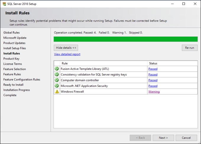
8. Select Database Engine Services and then click Next.
Figure 62. MS SQL Feature Selection
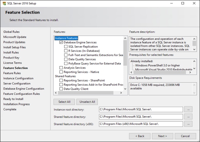
9. Retain the Default Instance and click Next and then click Next again.
10. Under Database Engine Configuration select Mixed Mode. Enter a password and add the current user as SQL Server administrator.
Figure 63. Database Engine Configuration
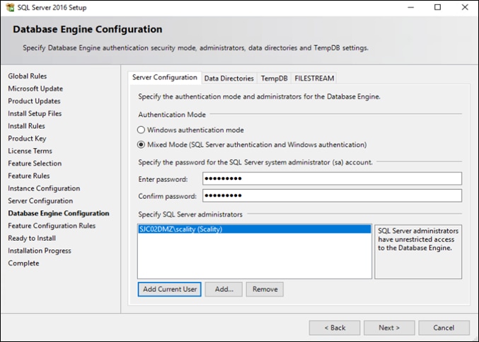
11. Click Next and then click Install.
12. Finally click Close. The MS SQL 2016 Server is then installed.
To change the firewall to allow communication to the NAS Archiver admin host, follow these steps:
1. Click the Windows Start menu and type in “firewall”. Select “Windows Firewall with Advanced Security.”
2. Click Inbound Rules and then click New Rule.
Figure 64. Windows Firewall with Advanced Security
![]()
![]()

3. Click Port and then click Next.
Figure 65. Windows Firewall Rule Type
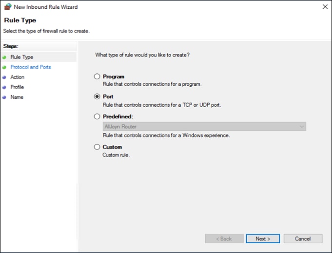
4. Select TCP, specify the ports 80 and 1433 and click Next.
Figure 66. Windows Firewall Protocols and Ports
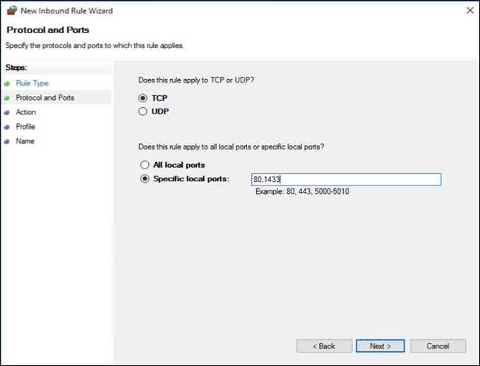
5. Select Allow the connection and click Next.
Figure 67. Windows Firewall Action
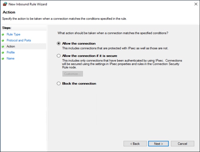
6. Under Profile select Domain and click Next.
Figure 68. Windows Firewall Profile
7. Provide a Name and click Finish.
Figure 69. Windows Firewall Name
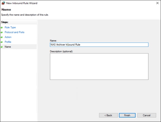
8. Repeat steps 1-7 for an outbound rule with a different name.
The following procedures document the installation and configuration of the Scality RING. The installation process is comprised of five unique stages listed below:
1. Prepare the Environment
2. Run the Pre-Install Suite
3. Install Scality RING
4. Install Scality S3 Connector Service
5. Run the Post-Install Suite
Download the Scality Offline installer with S3 from packages.scality.com. The Scality Installer archive comes with three package sets, each of which can be used for RING installation: Offline packages without S3, Offline packages with S3, and Online packages. Scality recommends using Offline packages for installation.
The installer leverages a platform description file to automate the RING installation process. Key to the automated RING installation process, the Platform Description File supplies information to the Scality Installer concerning the infrastructure on which the RING will be installed. It is generated from the Scality Sizing Tool, with system hardware information entered by Sales Engineers and technical details (for example hostnames, IP addresses, and RING definitions) entered by Customer Solutions Engineers.
The platform description file used for this CVD can be found in the Appendix.
![]() Contact your Scality sales representative for access to packages.scality.com and for help generating the platform description file.
Contact your Scality sales representative for access to packages.scality.com and for help generating the platform description file.
After downloading the installer ensure the root execution flag is set on the .run file.
$ chmod +x scality-ring-with-s3-offline.run
Invoke the installer with the --description-file option and pass the platform description file as the argument.
$ ./scality-ring-with-s3-offline.run --description-file /root/scality-sizing.csv
The Scality Installer Menu offers commands that correlate to major RING installation steps. These commands are presented in the sequence in which the installation steps are best followed.
The first step in an Automated Installation is to prepare the environment for RING installation. This includes setting up the required Scality and third-party repositories, deploying SaltStack to automate the installation and configuring the required OS kernel tunables.
To prepare the environment, follow these steps:
1. From the Scality Installer Menu select option 1 to prepare the environment.
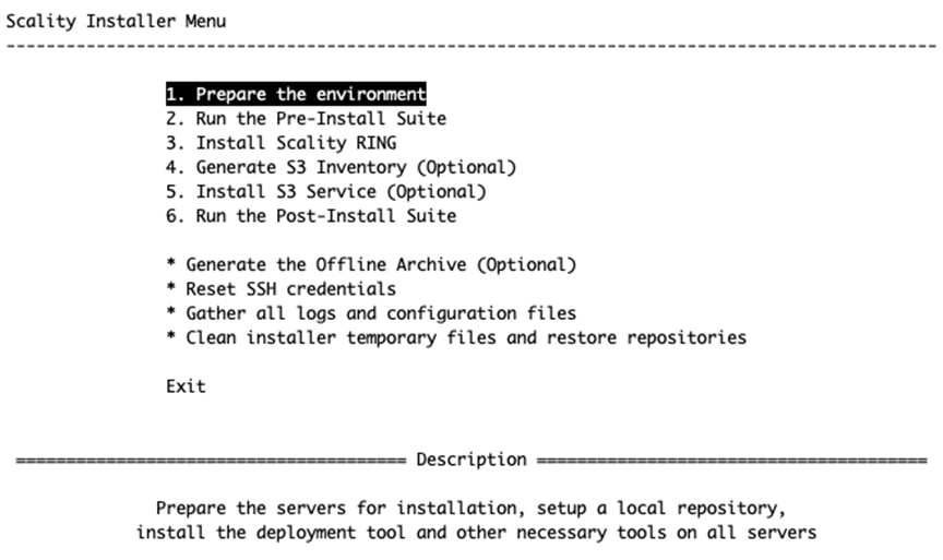
2. Select option 2, Private Key without passphrase.
![]() The first time an installer command is selected, you will be asked to select the SSH authentication method used to connect to each of the servers.
The first time an installer command is selected, you will be asked to select the SSH authentication method used to connect to each of the servers.
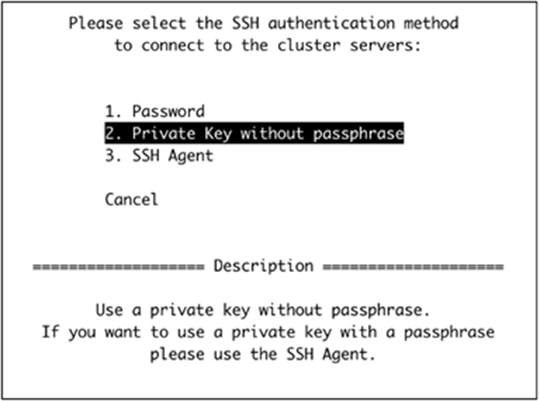
3. Provide the SSH user that will be used to connect to each of the servers.
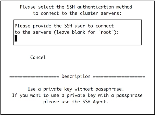
4. Provide the SSH key that will be used to connect to each of the servers.
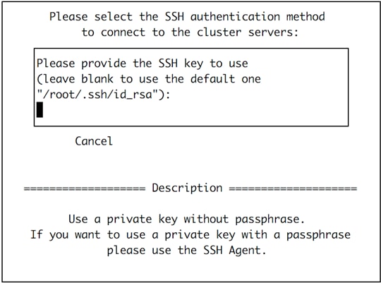
5. Choose option 1, enter a password.
![]() The Scality Supervisor UI requires a password.
The Scality Supervisor UI requires a password.
The installer will now prepare the environment:
[2020-08-17 16:08:40,615] Loading the platform description file '/root/platform.csv'... OK
[2020-08-17 16:08:40,630] Extracting platform description data... OK
[2020-08-17 16:08:40,632] Checking that bootstrap is run from supervisor server... OK
[2020-08-17 16:08:40,924] Generating the salt roster file '/etc/salt/roster'... OK
[2020-08-17 16:08:40,999] Preparing and testing SSH connection on every machine... OK
[2020-08-17 16:08:50,460] Performing server OS version correspondence check... OK
[2020-08-17 16:08:53,398] Checking iptables rules on every machine... OK
[2020-08-17 16:08:58,302] Generating the pillars for the install... OK
[2020-08-17 16:08:58,394] Installing scality-setup-httpd on 'cvd-super'... OK
[2020-08-17 16:09:07,929] Setting up the new repository definitions on every machine... OK
[2020-08-17 16:09:30,081] Tuning servers operating system |################################| 100.0% - ETA: 0:00:00
[2020-08-17 16:10:10,878] Tuning servers operating system... OK
[2020-08-17 16:10:10,878] Warning: Servers that need to be rebooted:
[2020-08-17 16:10:10,878] Warning: cvd-store-1, cvd-store-0, cvd-super, cvd-store-2
[2020-08-17 16:10:10,878] cvd-store-1: 0 failed, 9 skipped, 35 fixed
[2020-08-17 16:10:10,878] cvd-store-0: 0 failed, 9 skipped, 35 fixed
[2020-08-17 16:10:10,878] cvd-super: 0 failed, 10 skipped, 34 fixed
[2020-08-17 16:10:10,878] cvd-store-2: 0 failed, 9 skipped, 35 fixed
[2020-08-17 16:10:10,878] Details in /var/log/scality/setup/ostuning.log
[2020-08-17 16:10:11,975] Configuring logging on 'cvd-super'... OK
[2020-08-17 16:10:33,665] Configuring Scality SSH on every machine... OK
[2020-08-17 16:10:43,713] Installing python-six on every machine... OK
[2020-08-17 16:11:01,575] Installing sreport on every machine... OK
[2020-08-17 16:11:27,606] Installing hardware monitoring dependencies on every machine... OK
[2020-08-17 16:11:38,088] Installing salt-master on 'cvd-super'... OK
[2020-08-17 16:12:14,735] Installing SaltAPI on 'cvd-super'... OK
[2020-08-17 16:12:39,332] Installing salt-minion on every machine... OK
[2020-08-17 16:13:21,160] Accepting minion key(s) on the master instance... OK
[2020-08-17 16:13:48,470] Syncing configuration on every machine... OK
[2020-08-17 16:13:53,554] Cleaning roles on every machine... OK
[2020-08-17 16:13:54,534] Setting up roles on every machine... OK
[2020-08-17 16:14:04,697] Installing python Scality on every machine... OK
[2020-08-17 16:14:17,710] Generating Rings models for keyspace... OK
[2020-08-17 16:14:19,377] Installing scality-sprov... OK
[2020-08-17 16:14:30,435] Installing and configuring scaldisk on every machine... OK
[2020-08-17 16:14:38,576] Preparing disks for installation... OK
Warning: Tuning OS: Some changes require a reboot, the following servers need to be rebooted: cvd-store-1, cvd-store-0, cvd-super, cvd-store-2
-- Bootstrap step successful, duration: 0:06:01.590001 --
[2020-08-17 16:14:40,585] The bootstrap step finished successfully...
Press [Enter] to return to the menu or [Ctrl]+c to exit the installer
![]() After the Prepare the environment phase has completed, the servers may require a reboot as indicated in red above. Reboot the servers before proceeding to the next phase of the installation.
After the Prepare the environment phase has completed, the servers may require a reboot as indicated in red above. Reboot the servers before proceeding to the next phase of the installation.
To run the Pre-Install Suite, follow these steps:
1. After rebooting the servers, the installer can be relaunched with the following command:
$ /srv/scality/bin/launcher
2. Execute option 2 to run the pre-install checks. The pre-install checks verify the availability and accessibility of hardware servers and components as defined in the Platform Description File.
You can find the report at this URL: http://10.100.1.44:8000/platformcheck/report-20200817_181431
error: Command '['/srv/scality/bin/platformcheck', 'all', '--title', 'Scality Pre Install Suite', '--checks-filter', 'preinstall']' returned non-zero exit status 6
[2020-08-17 18:16:46,277] The preinstall step failed...
Press [Enter] to return to the menu or [Ctrl]+c to exit the installer
The results of the pre-install checks can be reviewed by navigating to the report URL provided when the pre-install checks are completed.
![]() Critical errors detected by the Pre-Install Suite should be addressed before proceeding.
Critical errors detected by the Pre-Install Suite should be addressed before proceeding.
To install the Scality RING, follow these steps:
1. Select option 3 to install Scality RING.
[2020-08-17 18:22:09,237] INFO - Launching install, this might take some time
[2020-08-17 18:22:09,270] <salt> Clear the cache and sync modules, grains and pillar ... OK
[2020-08-17 18:22:17,601] <roles> Check storage nodes minions matcher ... OK
[2020-08-17 18:22:17,602] <roles> Ensure grains is deleted everywhere ... OK
[2020-08-17 18:22:22,373] <roles> Setup supervisor role ... OK
[2020-08-17 18:22:24,705] <roles> Setup storage nodes role ... OK
[2020-08-17 18:22:29,253] <roles> Setup prometheus nodes role ... OK
[2020-08-17 18:22:36,108] <roles> Setup elasticsearch cluster role ... OK
[2020-08-17 18:22:38,413] <roles> Advertise elasticsearch cluster ... OK
[2020-08-17 18:22:48,305] <roles> Setup S3 role ... OK
[2020-08-17 18:23:07,870] <roles> Setup HALO role ... OK
[2020-08-17 18:23:12,248] <roles> Setup SPROXYD role ... OK
[2020-08-17 18:23:16,749] <setup> Start scality-setup-httpd ... OK
[2020-08-17 18:23:23,002] <setup> Install python-scality ... OK
[2020-08-17 18:23:30,256] <setup> Install python-scaldisk ... OK
[2020-08-17 18:23:36,770] <setup> Install sreport ... OK
[2020-08-17 18:23:48,685] <setup> Detect the disks ... OK
[2020-08-17 18:23:49,889] <setup> Publish disks infos ... OK
[2020-08-17 18:23:52,221] <sup> Bootstrap SupAPI database ... OK
[2020-08-17 18:24:08,786] <sup> Install and configure supervisor ... OK
[2020-08-17 18:26:57,903] <rings> Compute the keyspace ... OK
[2020-08-17 18:26:59,976] <rings> Configure the rings on the supervisor ... OK
[2020-08-17 18:27:44,959] <elastic> Install and configure elasticsearch cluster ... OK
[2020-08-17 18:29:15,076] <supapi> Configure the supapi service ... OK
[2020-08-17 18:29:37,988] <supapi> Install the cloud monitoring service ... OK
[2020-08-17 18:30:44,206] <disks> Partition and format disks ... OK
[2020-08-17 18:31:10,095] <disks> Mount all disks ... OK
[2020-08-17 18:31:14,177] <nodes> Install and configure storage nodes ... OK
[2020-08-17 18:33:56,213] <keyspace> Spread the keyspace to storage nodes ... OK
[2020-08-17 18:34:01,315] <keyspace> Make storage nodes join rings ... OK
[2020-08-17 18:34:06,682] <conns> Install sproxyd connectors ... OK
[2020-08-17 18:35:09,330] <conns> Install Scality Agent Daemon (sagentd) on S3 connectors ... OK
[2020-08-17 18:35:46,383] <post> Install and configure ringsh ... OK
[2020-08-17 18:35:57,338] <post> Backup the whole platform ... OK
[2020-08-17 18:36:07,152] <post> Install external tools ... OK
[2020-08-17 18:36:31,992] INFO - Install completed without errors
[2020-08-17 18:36:31,992] INFO - RING installed successfully
[2020-08-17 18:36:32,124] The install step finished successfully...
Press [Enter] to return to the menu or [Ctrl]+c to exit the installer
To install the S3 connector service, follow these steps:
1. Select option 4 to generate the S3 inventory. The inventory file describes the architecture of the S3 installation and is generated using the information in the platform description file.
[2020-08-17 18:48:08,929] Searching S3 offline archive file... OK
[2020-08-17 18:48:08,929] Extracting S3 offline archive... OK
[2020-08-17 18:48:52,937] Generating the S3 inventory from platform description file... OK
[2020-08-17 18:49:03,450] Installing sshpass package... OK
[2020-08-17 18:49:10,635] The bootstraps3 step finished successfully...
Press [Enter] to return to the menu or [Ctrl]+c to exit the installer
2. The Install the S3 Service (Optional) menu command installs the S3 Connector components on the nodes as described in the Platform Description File.
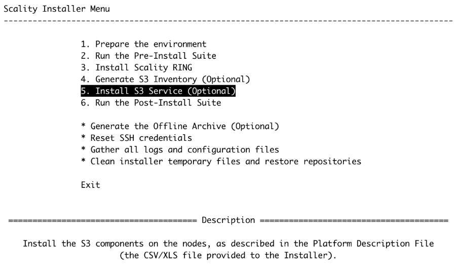
[2020-08-17 18:50:07,203] Searching S3 offline archive file... OK
[2020-08-17 18:50:07,204] Extracting S3 offline archive... OK
[2020-08-17 18:50:09,268] Installing sshpass package... OK
[2020-08-17 18:50:15,330] Generating vault environment configuration... OK
[2020-08-17 18:50:24,115] Running S3 ansible playbook to install the S3 connector... OK
[2020-08-17 19:06:41,084] Setting up the identisee credentials... OK
[2020-08-17 19:06:57,257] The s3 step finished successfully...
Press [Enter] to return to the menu or [Ctrl]+c to exit the installer
To run the post-install suite, follow these steps:
1. Issue the Run the Post-Install Suite menu command to validate the installation.
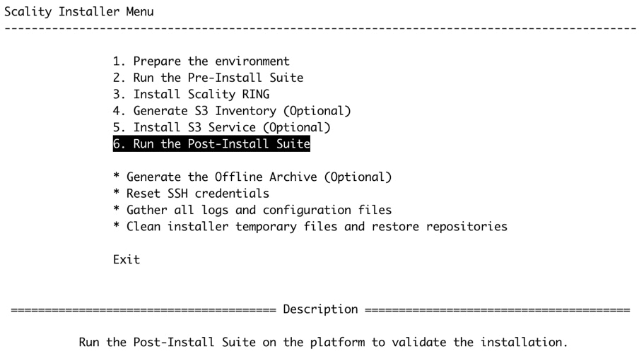
Report generated in '/srv/scality/repository/platformcheck/report-20200817_202929'.
You can find the report at this URL: http://10.100.1.44:8000/platformcheck/report-20200817_202929
error: Command '['/srv/scality/bin/platformcheck', 'all', '--title', 'Scality Post Install Suite', '--checks-filter', 'postinstall']' returned non-zero exit status 6
[2020-08-17 20:32:00,061] The postinstall step failed...
Press [Enter] to return to the menu or [Ctrl]+c to exit the installer
The results of the Post-Install Suite should be shared with your Scality Service or Support representative for review. The results can be found at /root/post-install-checks-results.tgz. The results can also be review by navigating to the provided URL.
Manage and Monitor Scality RING
Managing and monitoring the RING is enabled through a cohesive suite of user interfaces, built on top of a family of RESTful interfaces termed the Supervisor API (SupAPI). RING 7 includes the new Scality Supervisor, a browser-based portal for both systems monitoring and management of Scality components. In RING 7, the Supervisor now provides capabilities across object (S3) and file (NFS, SMB, FUSE) Connectors including integrated dashboards including Key Performance Indicators (KPIs) with trending information such as Global Health, Performance, Availability and Forecast.
The Scality Supervisor can be accessed in a browser via the IP address of the Supervisor server.
To monitor the Scality RING, follow these steps:
1. Launch the Scality Supervisor by navigating to http://<supervisor IP>/gui.
2. Login using the user admin and the password provided during the Preparing the Environment step of the installation.
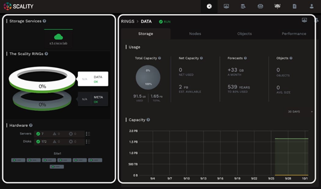
The Component Panel (left) provides an overview of the overall platform health including hardware and services. Services in a failed or critical state will be colored red indicating attention is needed.
The Information Screen (right) provides a capacity overview. The Forecasts section provides the storage administrator with a projected time to 80% full.
To configure and access NFS exports on the Scality Scale-Out Filesystem (SOFS), follow these steps:
1. Volumes are created through the RING Supervisor UI. To access the RING Supervisor UI, navigate to http://<supervisor IP>/gui.
2. Login using the user admin and the password provided during the Preparing the Environment step of the installation.
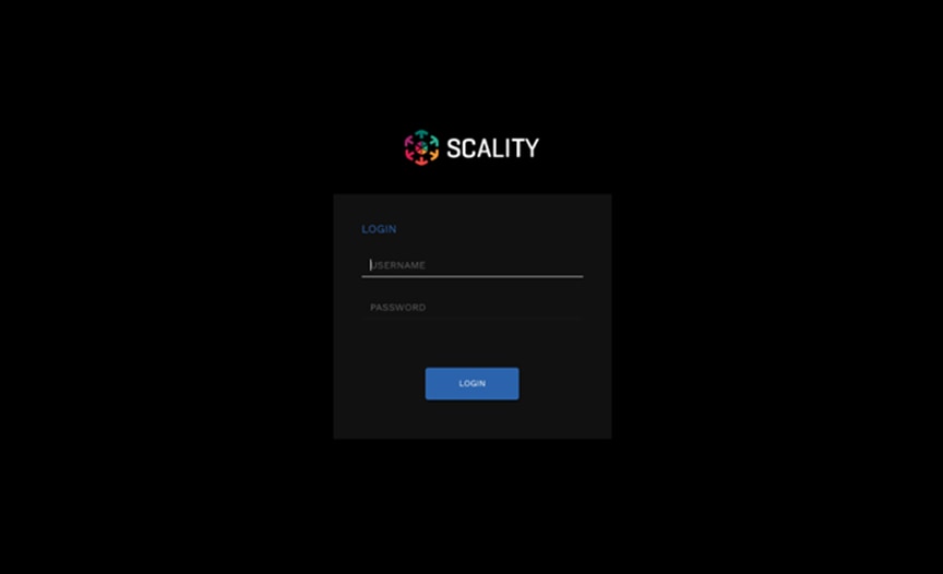
3. Navigate to the Operations>Volumes menu.
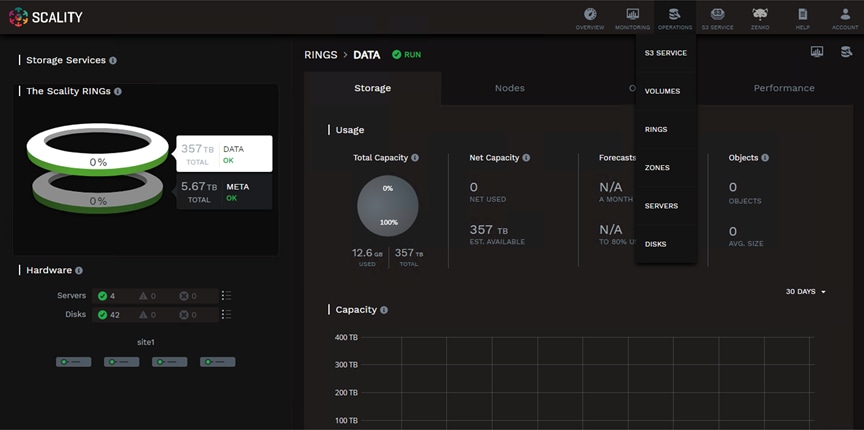
4. Click the + button to create a new volume.
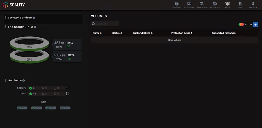
5. Provide a volume name, select the backend RINGs, and protection level then click Create:
◦ Name: volume1
◦ Backend RINGs: DATA+META
◦ Protection Level: 3 Servers Erasure Coding (E.C. 7+5)
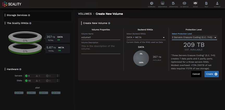
6. Configuration Groups allow the user to group connectors with identical configurations. A new Configuration Group must be created for the NFS connectors. Select NFS from the drop-down list.
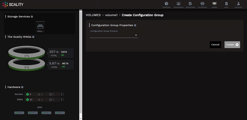
7. Provide a configuration group name.
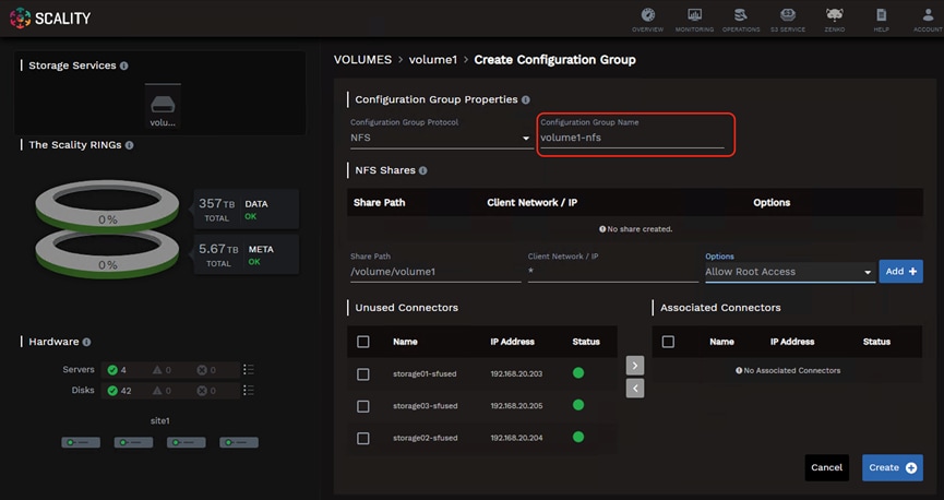
8. Define the share details and click Add +:
◦ Share Path: /volume/volume1
◦ Client Network/IP: *
◦ Options: Allow Root Access
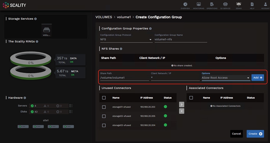
9. Associate the unused connectors with the configuration group.
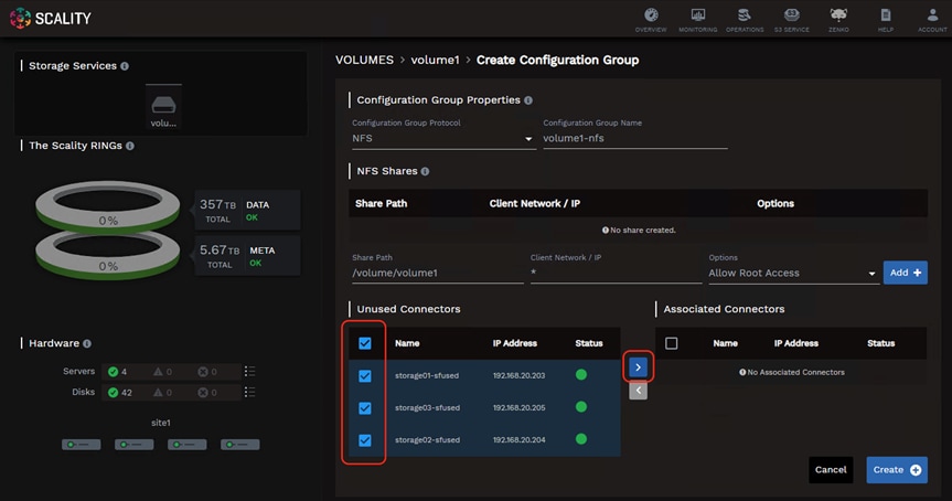
10. Click Create.
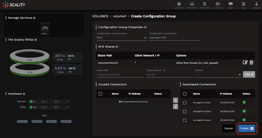
The Scality S3 Connector provides a full implementation of the AWS multi-tenancy and identity management (AWS IAM) model with federated authentication to LDAP and Active Directory to integrate into enterprise deployment environments. In addition to the RING Supervisor management UI, the S3 Service Provider UI is a web-based user interface to manage multi-tenancy accounts, users, group, and policies.
To create a new S3 account through the S3 console, follow these steps:
1. To connect to the S3 Console navigate to the S3 Service drop-down list in the Scality Supervisor and select S3 Console.
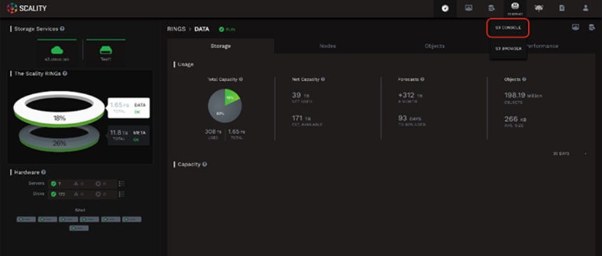
2. Login using the user admin and the password provided during the Preparing the Environment step of the installation.
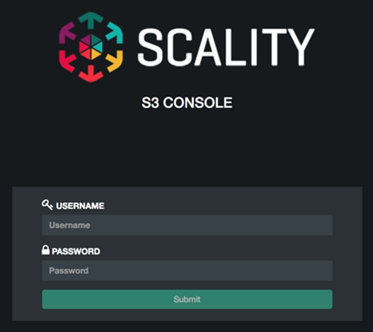
3. Click Create account to create a new S3 account.

4. Provide an account name, email and password then click Submit.
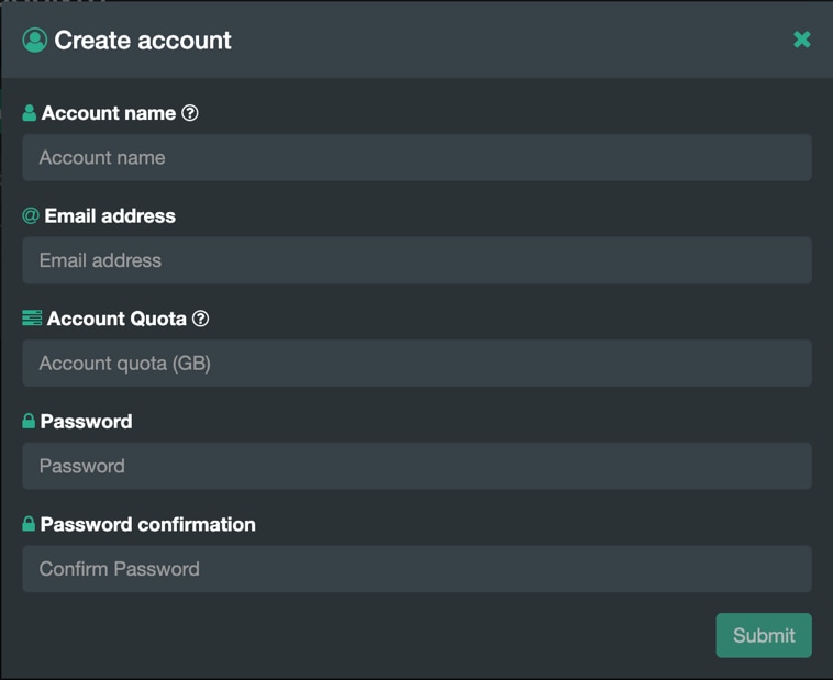
You can view the new account in the accounts table.
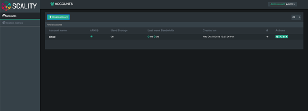
![]() The S3 Console can be used to manage users. To create a new user under the ‘cisco’ account created in the previous section and log into the S3 Console using the user ‘cisco’ and the password provided.
The S3 Console can be used to manage users. To create a new user under the ‘cisco’ account created in the previous section and log into the S3 Console using the user ‘cisco’ and the password provided.
5. Click the + button to create a new user.
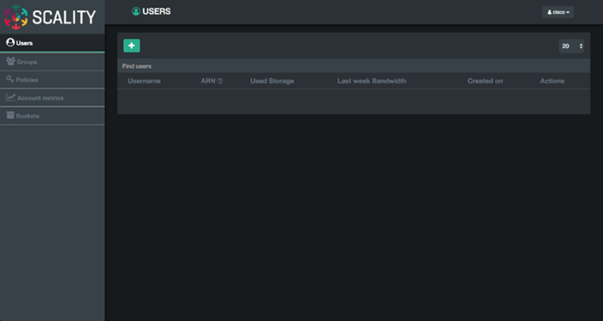
6. Provide a Username, select the FullAccessGroup to grant the user full permissions, and click Submit.
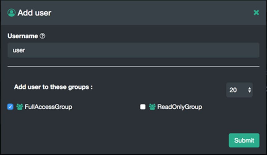
After clicking Submit the user will appear in the users table.
7. To generate the secret key and accesskey required to end S3 requests click the Users Key icon in the Actions column.
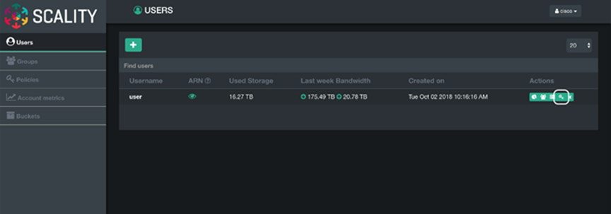
8. Click the Generate a new key button to generate the secrete key and access key.
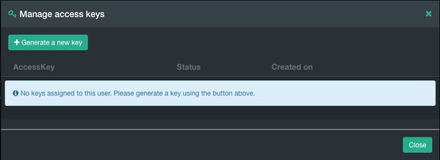
9. Confirm the key generation by clicking Proceed.
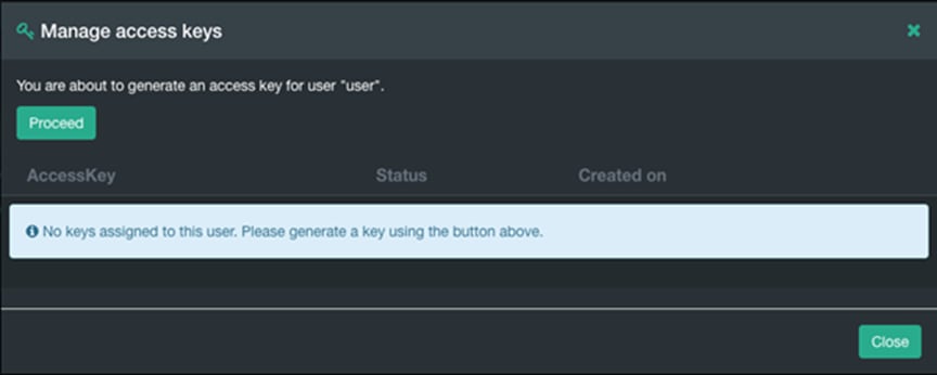
![]() For security reasons the secret key can only be viewed at creation time. Record the secret key in a safe location. If the secret key is lost generate a new secret key and access key can be generated from the S3 Console.
For security reasons the secret key can only be viewed at creation time. Record the secret key in a safe location. If the secret key is lost generate a new secret key and access key can be generated from the S3 Console.
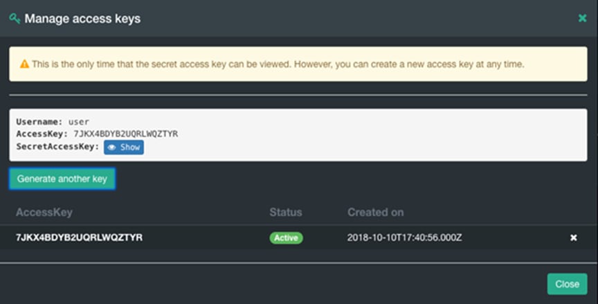
The AccessKey and SecretAccessKey can be used to connect to the S3 endpoint using command line tools like awscli or s3cmd or directly in any application which supports the S3 API.
Scality also provides an S3 Browser that can be used browse or create buckets and upload objects. To connect to the S3 Console navigate to the S3 Browser drop-down list in the Scality Supervisor and select S3 Browser.
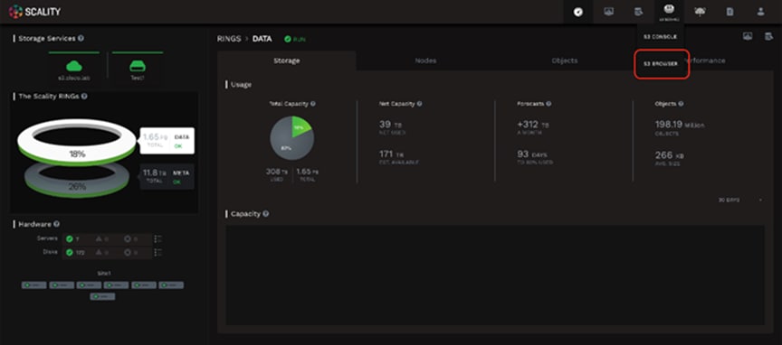
The AccessKey and SecretKey can be used to login.
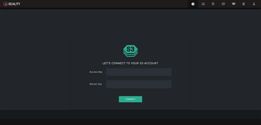
You can browse, upload, download, and delete buckets and objects.
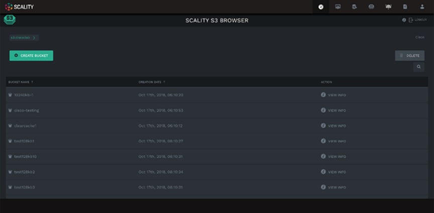
Installation of Scality NAS Archiver
Prepare Scality NAS Archiver Portal Server
This section provides the installation process of the NAS Archiver on the Portal server, the SQL server, and the target server.
![]() We already downloaded the NAS Archiver installer and copied it to all hosts.
We already downloaded the NAS Archiver installer and copied it to all hosts.
Start with the Portal server for NAS Archiver. To install the NAS Archiver, follow these steps:
1. Connect via Remote Desktop to the NAS Archiver Portal host.
2. Go to the directory where the NAS Archiver is stored and then to the subdirectory Admin.
3. Double-click Setup to start the installation.
The Welcome screen appears.
Figure 70. Scality NAS Archiver Welcome Screen
4. Click Next and accept the license agreement. Click Next.
5. Choose your destination folder and click Next.
Figure 71. Scality NAS Archiver Destination Folder
6. Use the default web site in the next screen. Retain the default information and click Next.
Figure 72. Scality NAS Archiver Web Application
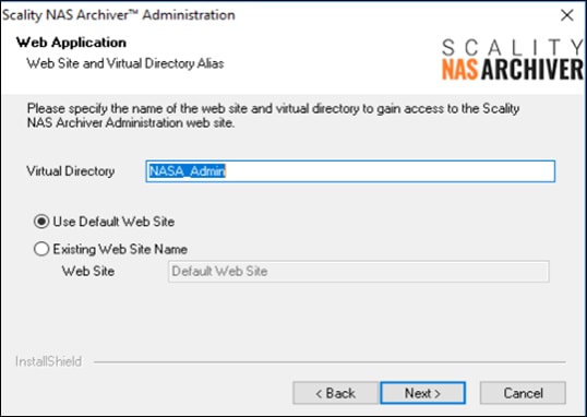
7. For Configuration Database Selection enter the IP Address or the FQDN and click Next.
Figure 73. Configuration Database Selection for Scality NAS Archiver
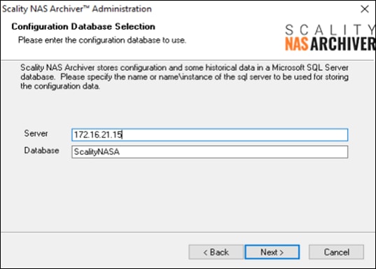
8. A pop-up window appears and asks whether you want to create the configuration database and tables automatically. Answer Yes.
9. For SQL Security leave Integrated Security as the default and click Next.
Figure 74. Scality NAS Archiver SQL Security
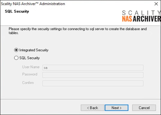
10. For the Secondary Stores Database Selection leave everything untouched and click Next.
Figure 75. Scality NAS Archiver Secondary Stores Database Selection
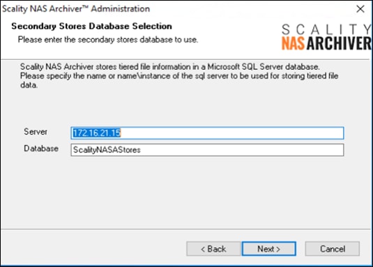
11. A pop-up window appears and asks whether you want to create the secondary stores database and tables automatically. Answer Yes.
12. Click Next for SQL Security and leave it as Integrated Security.
13. Type in the Domain\Account and the password for the account and click Next and then click OK.
Figure 76. Scality NAS Archiver Product Installer Service Configuration
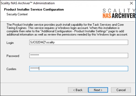
14. Prior to entering a UNC Path, you must first create this path on the Portal host. Open Explorer and create a directory under C:\ and click Share.
Figure 77. File Share
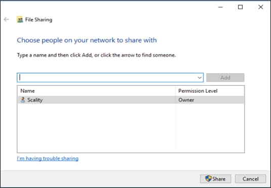
Figure 78. Share Path for UNC Path
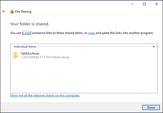
15. Click copy and return to the NAS Archiver installation window and paste it into the UNC Path field. Make sure it has a UNC Path name format and click Next.
Figure 79. UNC Path
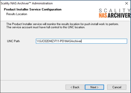
16. Type in the company name, and an email address. If you have a Production Version, then type in the code and click Next.
Figure 80. Contact Information
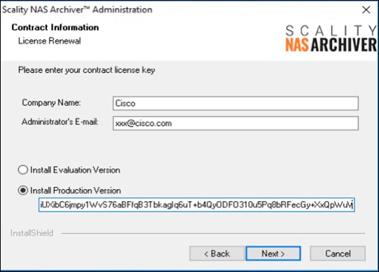
17. Select the Program Folders and click Next.
18. Verify everything and click Next. When the installation finishes, click Finish.
This section details the Windows File Server you’re going to use to archive data to Scality RING. To enable the archiving functionality on the server, you need to install the Core Tiering Engine and the Task Service.
To install the NAS Archiver Core Tiering Engine and the Task Service, follow these steps:
1. Connect via Remote Desktop to the Windows File Server.
2. Go to the directory where the NAS Archiver is stored and then to the subdirectory Admin.
3. Double-click on setup to start the installation.
4. The Welcome screen appears. Click Next.
Figure 81. Core Tiering Engine Welcome Screen
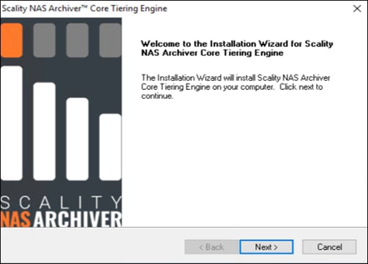
5. Accept the License Agreement and click Next.
6. Choose your destination location and click Next.
7. Click Next again to start the installation process.
Figure 82. Start Copying Files
8. Click Finish. The Core Tiering Engine is now installed.
To install the Task Service, follow these steps:
9. Return to the directory of the NAS Archiver and go to Task Service -> Win32 and double-click Setup.
10. The Welcome screen appears. Click Next.
Figure 83. Task Service Welcome Screen
11. Accept the License Agreement and click Next.
12. Choose your destination location and click Next.
13. In the Agent Configuration window type in your domain account, that has access to the SQL database and then click Next. Click OK.
Figure 84. Agent Configuration
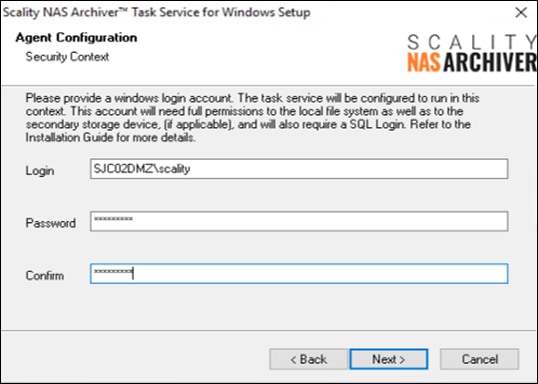
14. Enter now the FQDN name of the Portal host in the <webserver> field and click Next.
Figure 85. Scality NAS Archiver Administration Web Site
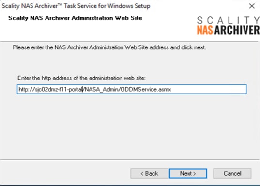
15. Click Next again to start the installation process.
Figure 86. Start Copying Files
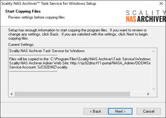
16. Click Finish, then click OK and click Finish again. The Service Task is now installed.
Configuration of Scality NAS Archiver
After installing the NAS Archiver software on all required hosts, you need to configure the Portal server for the primary and secondary storage to enact the archiving process.
![]() When opening the NAS Archiver window for the first time it is important to backup the master key of the NAS Archiver Administration site.
When opening the NAS Archiver window for the first time it is important to backup the master key of the NAS Archiver Administration site.
1. On the NAS Archiver Portal server open the windows menu and start NAS Archiver Administration under Scality NAS Archiver.
2. Login with your domain account you used during installation.
3. When the NAS Archiver window opens, you can see a yellow banner with a link Master Key.
Figure 87. Main NAS Archiver window with Master Key Backup Option
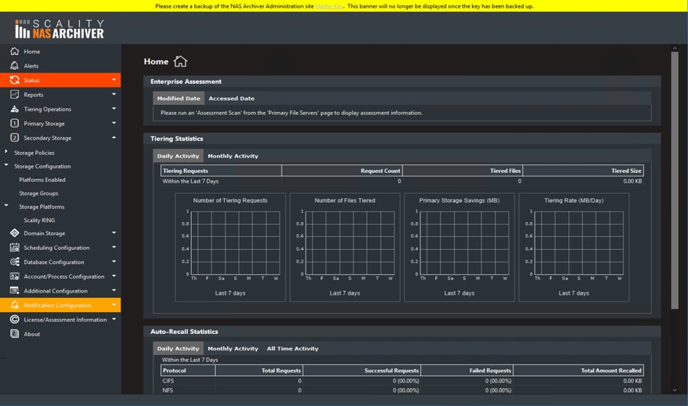
4. Click the link and then Export to save the master key.
Figure 88. Export Master Key
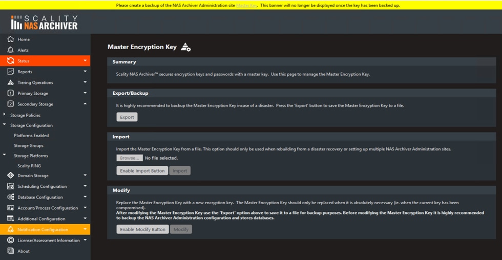
5. Click Save it and the key file is stored in the Downloads folder. Move the file to a safe location.
6. Click Secondary Storage -> Storage Configuration -> Storage Platform -> Scality RING and then New Store.
7. Type in a Secondary Storage Name.
8. For the Primary Address type in an address with the format bucket.fqdn or bucket.namespace.fqdn. In this case we created a bucket archiver on the Scality RING and configured the DNS server with a subdomain s3.sjc02dmz.net for all three connectors.
9. Specify the Primary Port. If needed, please checkmark Use Secure Connection (SSL).
10. Type in Primary Access ID and Primary Access Key, which you created before.
11. Click Add.
Figure 89. Configure Secondary Storage
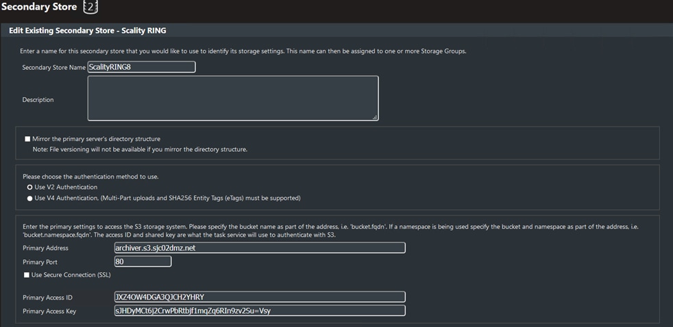
12. Click Scality RING8 and scroll down to the end. Click Test Connection and then click OK. You should see a green message that the connection has been established.
13. Click Secondary Storage -> Storage Configuration -> Storage Groups and then Make This Type the Default for Scality RING.
14. Click New Secondary Storage Group.
15. Type in a Group Name and select under Secondary Store Name the previous created Storage Platform. Click Assign and then click Add.
Figure 90. Secondary Storage Group
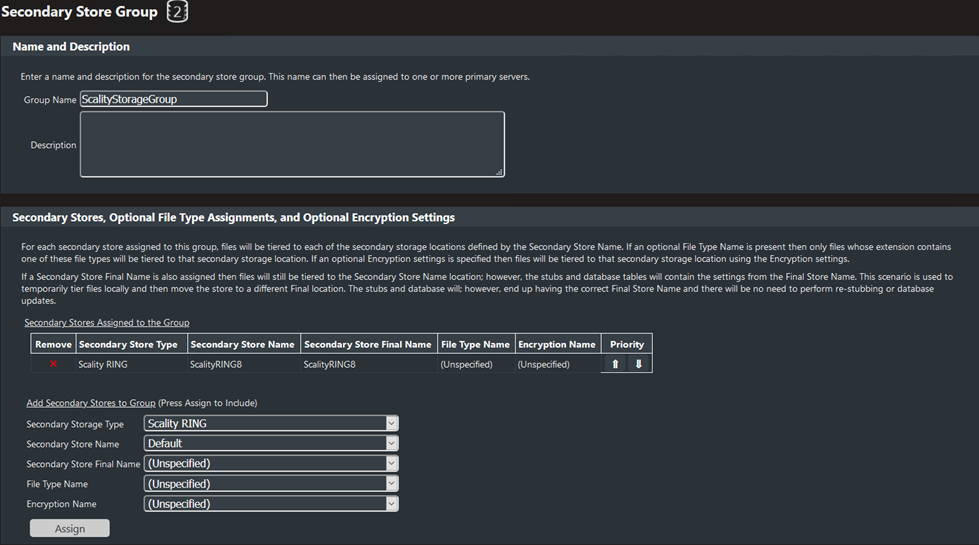
16. Click Primary Storage -> Primary File Servers. Click the name of the primary file server.
17. Under Secondary Storage Group select the previously created storage group and click Update.
18. The red color around Status and Primary Storage Status on the left should now disappear.
Configure a Scality NAS Archiver Schedule
To enable automated archiving from the Windows File Server to Scality RING you need to define scan policies, define the primary server scan settings and setup a schedule, which archives data via pre-defined rule.
![]() In this CVD we describe an example setup for a tiering policy. This has to be changed for a production environment.
In this CVD we describe an example setup for a tiering policy. This has to be changed for a production environment.
Set Up Scan Policies
You need to define a scan policy, which defines what files should be tiered to the secondary storage location, and to do so, follow these steps:
1. Go to Tiering Operations -> Core Tiering Engine -> Scan Policies and click New CTE Scan Policy.
2. Type in a Scan Policy Name.
3. Change under Date Settings -> Modified the Modified date to 7 days.
4. Click under Accessed select Do not capture based on accessed date.
5. Click Add.
Figure 91. Core Tiering Engine Scan Policy
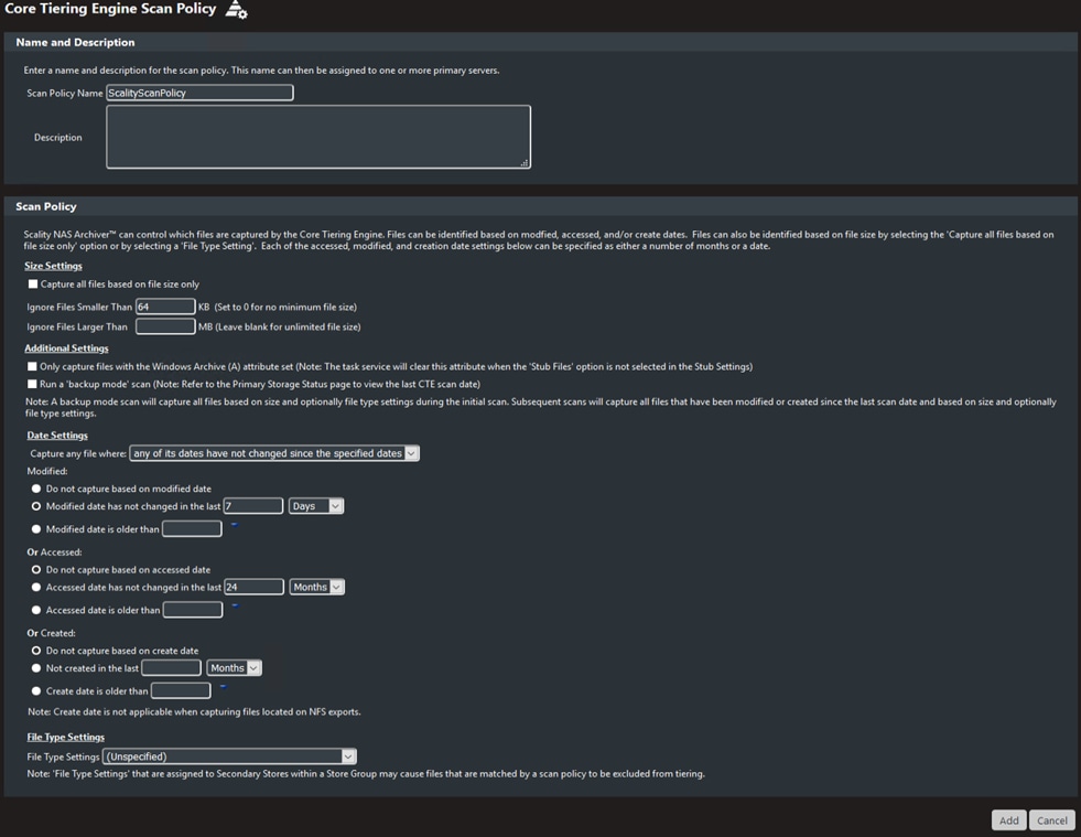
Configure Scan Policies
To configure the scan policies for the target server, in our case a Windows File Server, follow these steps
1. Go to Primary Storage -> Primary File Servers and click Shares of the Windows File Server.
Figure 92. Primary File Servers
![]()
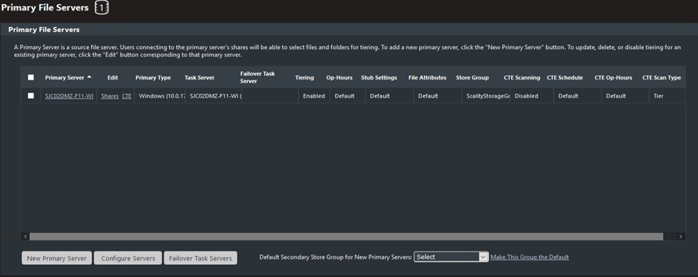
2. Click D$ and change the Scan Policy to the previously created scan policy.
3. Click Add to CTE Scan Locations. You will see a green message at the bottom about the successful adding of the share.
Figure 93. Primary File Server Shares
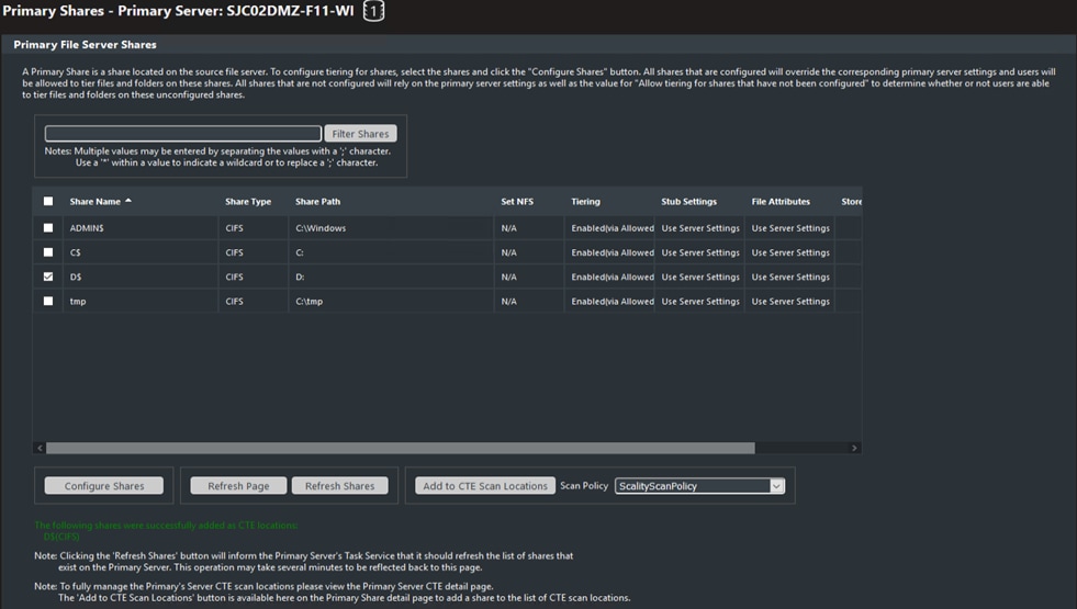
4. Click Refresh Shares. You will see another green message about the successful refresh.
5. Click Primary File Servers and then click CTE of the Windows File Server.
6. Under Core Tiering Engine select Scanning Enabled.
7. Under Scan Specific Locations select the previously created scan policy for Scan Policy.
8. In the List of Specific Locations click the shown share. Click Update.
Figure 94. Core Tiering Engine Windows File Server
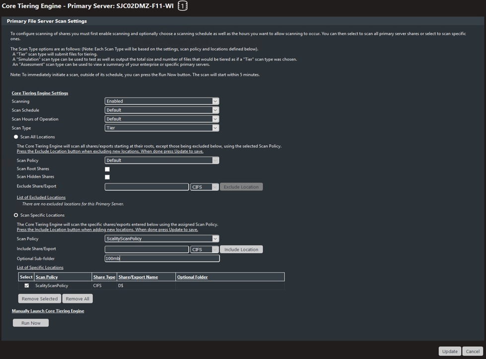
Schedule Setup
To modify the schedule for the Core Tiering Engine, follow these steps:
![]() In our case we changed the default schedule to minimum to start with the tiering at the next available point in time.
In our case we changed the default schedule to minimum to start with the tiering at the next available point in time.
1. Go to Scheduling Operations -> Schedule Settings and click Default.
2. Change the Frequency to Daily and click Update.
Figure 95. Schedule Settings
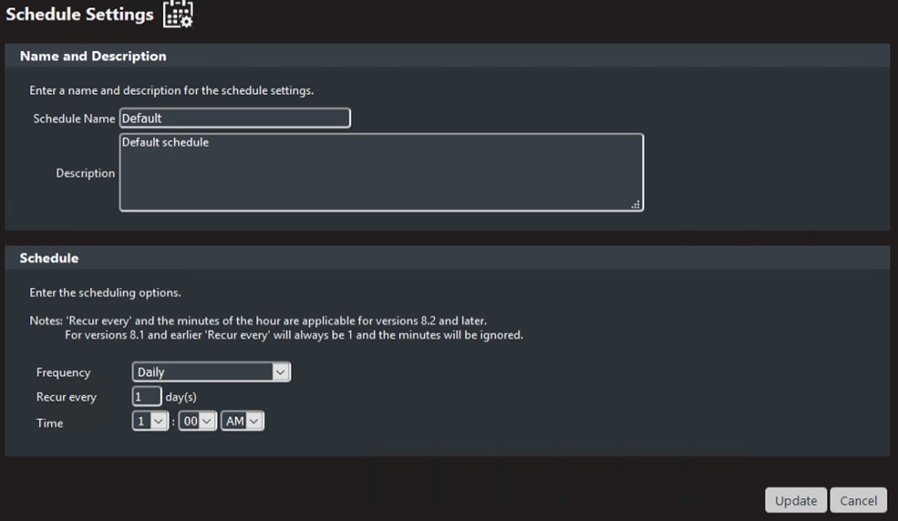
Another way of archiving data is Right-Click-Tiering. With that you could immediately archive data whenever you want by just a right-click on a specific file and then tier that file. With a double-click on the stub, you can easily read the file again. To configure right-click-tiering, follow these steps:
1. Go to the installation folder of the Scality NAS Archiver and then to the subfolder RightClickTiering -> X64 and double-click Right-Click Tiering x64.
2. Click Next and accept the license agreement. Click Next and then click Next again and fill-in the name or IP address of the Scality NAS Archiver Portal Server.
Figure 96. NAS Archiver Administration Web Site
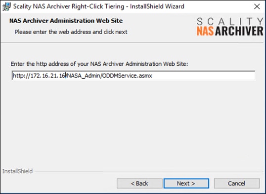
3. Click Next and then click Install and then click Finish.
4. To test Right-Click-Tiering open Windows Explorer on the Portal Server and mount the share from the Windows File Server we use in our example. Go to one of the subdirectories, select a file and right-click Tier File.
Figure 97. Right-Click-Tiering
![]()
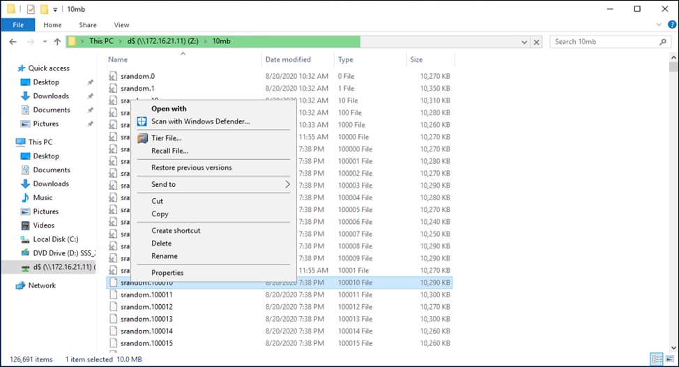
5. A window opens. Click Tier and then click Yes and then click Close. The file is now going to be archived to the Scality RING and the icon of the file changes to ![]() . You can easily recall the file by right-click Recall File or by double-clicking on the stub.
. You can easily recall the file by right-click Recall File or by double-clicking on the stub.
Scality RING Performance Testing
Performance was evaluated on the Scality RING running on Cisco UCS C240 M5 hardware. The goal of the performance testing was to evaluate peak object performance under ideal conditions.
S3 performance testing was conducted with COSBench the standard cloud object storage benchmark. Six virtual machines were used as COSBench drivers to generate the object workload.
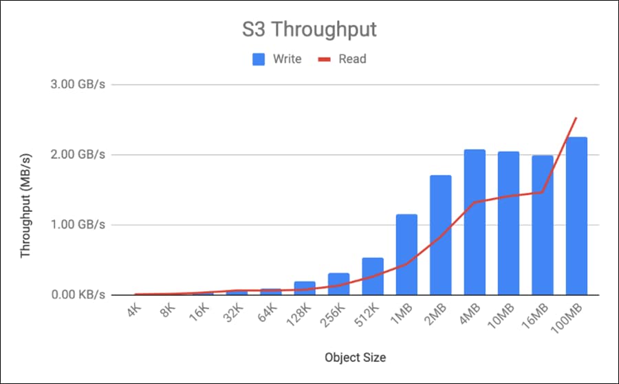
● Read bandwidth peaks at 2.53 GB/s at an object size of 100MB. This translates to a disk performance of 72 MB/s/disk.
● Write bandwidth peaks at 2.26 GB/s at an object size of 100MB. This translates to a disk performance of 64 MB/s/disk.
The Scality RING configuration used for this CVD was sized for functional testing only. There are many factors to consider when sizing RING for high performance use cases. Please contact Scality for more information.
Scality RING High Availability Testing
It is important for business continuity to help ensure high availability of the hardware and software stack. Some of these features are built into the Cisco UCS Infrastructure and enabled by the software stack and some of these features are possible from the Scality RING Storage software itself. To properly test for high availability, the following considerations were given priority:
● The Scality RING deployment will process a reasonable amount of load when the fault is triggered. Total throughput will be recorded for S3 from the COSBench interface and for NFS from Linux fio command.
● Only a single fault will be triggered at any given time. Double failure is not a part of this consideration.
● Performance degradation is acceptable and even expected, but there should be no business interruption tolerated. The underlying infrastructure components should continue to operate within the remaining environment.
The following High Availability tests were performed:
● Cisco Nexus 93180YC-EX Switch A failure
● Cisco UCS C240 M5 – Scality RING storage node disk failure
● Cisco UCS C240 M5 – Scality RING storage node failure
These testes will be performed for S3 and NFS protocol.
As indicated previously, a reasonable amount of load will be defined as follows:
● The COSBench application will be configured to send a steady stream of data to the Scality RING cluster.
Figure 98. High Availability Testing
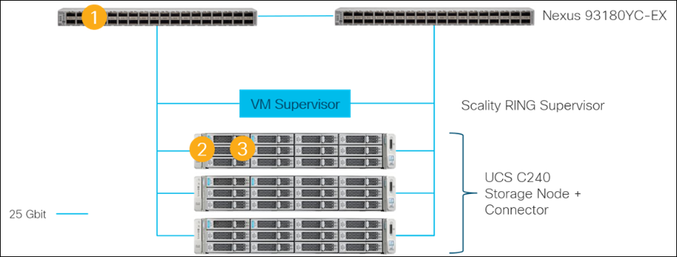
Cisco Nexus 93180YC-EX High Availability Testing
1. Connect to Cisco Nexus 93180YC-EX Switch A and make sure running-config is copied to startup-config to make certain no configuration changes are lost during power cycle.
sjc02dmz-f9-n93180ycex-a# copy run start
[########################################] 100%
Copy complete, now saving to disk (please wait)...
Copy complete.
2. Initiate load to the cluster by utilizing COSBench.
3. Initiate a reload command to reboot the switch.
sjc02dmz-f11-n93180ycex-a(config)# reload
This command will reboot the system. (y/n)? [n] y
![]()
![]()
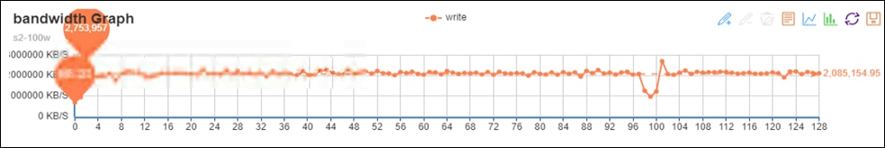
Aside from loss of response from Nexus 93180YC-EX switch, Scality RING environment remained functional, load continued with a small interruption, and redundancy was reestablished upon Switch A completing the reboot process. There was only a small loss in bandwidth between both red lines, but traffic continued.
Cisco UCS C240 M5L Disk Failure Testing
1. Connect to one of the storage nodes.
2. Initiate load to the cluster by utilizing COSBench.
3. Delete one of the virtual drives with storcli.
# /opt/MegaRAID/storcli/storcli64 /c0 /v2 delete force
The graph below is a snapshot from COSBench.
![]()
![]()
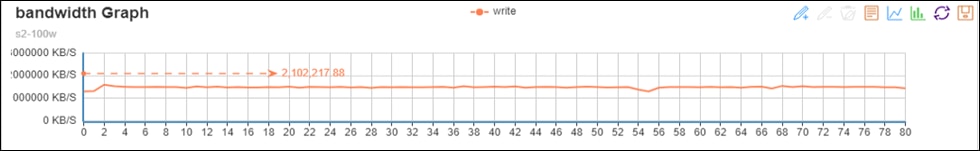
There was only a small loss in bandwidth between both red lines when the virtual disk was deleted. The workload recovered quickly.
Cisco UCS C240 M5L Node Failure Testing
1. Connect to Cisco Intersight and verify that the node is in a known good working condition.
2. Initiate load to the cluster by utilizing COSBench.
3. Power off one of the storage nodes.
The graph below is a snapshot from COSBench. At the vertical red line is where storage-node1 was powered off. A loss in throughput of about 30 percent was observed. The cluster started the self-healing process, but no traffic interruption was observed. Because of the small cluster with just three nodes, the recovery took longer but finally came back to a normal state after the third node joined the cluster.
![]()
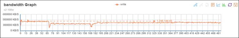
As indicated previously, a reasonable amount of load will be defined as follows:
● With fio under Linux a steady stream of data will be send to the Scality RING cluster.
Cisco Nexus 93180YC-EX High Availability Testing
Sequence of Events
1. Connect to Cisco Nexus 93180YC-EX Switch A and make sure running-config is copied to startup-config to make certain no configuration changes are lost during power cycle.
sjc02dmz-f9-n93180ycex-a# copy run start
[########################################] 100%
Copy complete, now saving to disk (please wait)...
Copy complete.
2. Initiate load to the cluster by utilizing fio under Linux.
3. Initiate a reload command to reboot the switch.
sjc02dmz-f11-n93180ycex-a(config)# reload
This command will reboot the system. (y/n)? [n] y
![]()
![]()
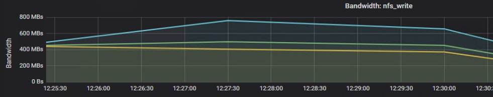
Between both red lines.
Cisco UCS C240 M5L Disk Failure Testing
Sequence of Events
1. Connect to one of the storage nodes.
2. Initiate load to the cluster by utilizing fio under Linux.
3. Delete one of the virtual drives with storcli.
[root@sjc02dmz-f11-storage1 ~]# date && /opt/MegaRAID/storcli/storcli64 /c0 /v10 delete force
Wed Sep 9 13:28:36 PDT 2020
Controller = 0
Status = Success
Description = Delete VD succeeded
![]()
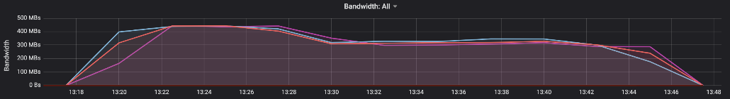
At the red line there is a small loss of throughput, which is understandable given the fact that the cluster was under high load.
Cisco UCS C240 M5L Node Failure Testing
Sequence of Events
1. Connect to Cisco Intersight and verify that the node is in a known good working condition.
2. Initiate load to the cluster by utilizing dd under Linux.
3. Power off one of the storage nodes.
![]()
![]()
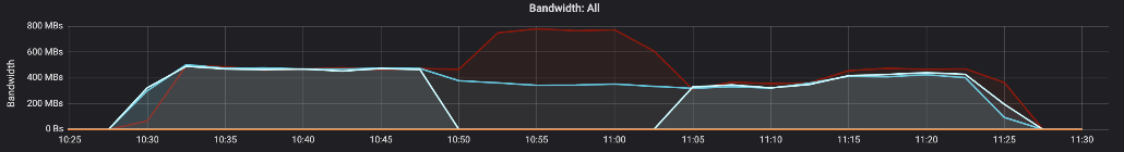
The server was powered off at the first red line and the VIP fails over to one of the two remaining servers. The server taking over the VIP now handles almost 2/3 of the incoming traffic. At the second red line all three servers were up and running and traffic gets normal after a few minutes.
Firmware Upgrade Terraform Configuration File
resource "intersight_firmware_upgrade" "sds-firmware-update" {
upgrade_type = "network_upgrade"
network_share {
map_type = "www"
http_server {
location_link = "http://172.16.21.14/images/ucs-c240m5-huu-4.1.1f.iso"
}
}
server {
object_type = "compute.RackUnit"
moid = var.storage-node1
}
}
Infrastructure Terraform Configuration File for Policies
resource "intersight_adapter_config_policy" "scality-adapter-config-policy" {
name = "scality-adapter-config-policy"
description = "Adapter Configuration Policy for Scality"
organization {
object_type = "organization.Organization"
moid = var.org_moid
}
settings {
dce_interface_settings {
fec_mode = "cl74"
interface_id = "0"
}
dce_interface_settings {
fec_mode = "cl74"
interface_id = "1"
}
dce_interface_settings {
fec_mode = "cl74"
interface_id = "2"
}
dce_interface_settings {
fec_mode = "cl74"
interface_id = "3"
}
slot_id = "1"
eth_settings {
lldp_enabled = true
}
fc_settings {
fip_enabled = false
}
}
profiles {
moid = intersight_server_profile.storage-node1.id
object_type = "server.Profile"
}
profiles {
moid = intersight_server_profile.storage-node2.id
object_type = "server.Profile"
}
profiles {
moid = intersight_server_profile.storage-node3.id
object_type = "server.Profile"
}
}
output "out1" {
value=intersight_adapter_config_policy.scality-adapter-config-policy
}
resource "intersight_vnic_eth_adapter_policy" "scality-ethernet-adapter-policy" {
name = "scality-ethernet-adapter-policy"
description = "Ethernet Adapter Policy for Scality"
rss_settings = true
organization {
object_type = "organization.Organization"
moid = var.org_moid
}
vxlan_settings {
enabled = false
}
nvgre_settings {
enabled = false
}
arfs_settings {
enabled = false
}
interrupt_settings {
coalescing_time = 125
coalescing_type = "MIN"
nr_count = 32
mode = "MSI"
}
completion_queue_settings {
nr_count = 16
ring_size = 1
}
rx_queue_settings {
nr_count = 8
ring_size = 4096
}
tx_queue_settings {
nr_count = 8
ring_size = 4096
}
tcp_offload_settings {
large_receive = true
large_send = true
rx_checksum = true
tx_checksum = true
}
}
resource "intersight_vnic_eth_network_policy" "scality-client-network" {
name = "scality-client-network"
description = "Client Network for Scality"
organization {
object_type = "organization.Organization"
moid = var.org_moid
}
vlan_settings {
default_vlan = var.client_vlan
mode = "TRUNK"
}
}
resource "intersight_vnic_eth_network_policy" "scality-storage-network" {
name = "scality-storage-network"
description = "Storage Network for Scality"
organization {
object_type = "organization.Organization"
moid = var.org_moid
}
vlan_settings {
default_vlan = var.storage_vlan
mode = "TRUNK"
}
}
resource "intersight_vnic_eth_qos_policy" "scality-ethernet-qos-policy" {
name = "scality-ethernet-qos-policy"
description = "Ethernet quality of service for Scality"
mtu = 9000
rate_limit = 0
cos = 0
trust_host_cos = false
organization {
object_type = "organization.Organization"
moid = var.org_moid
}
}
resource "intersight_vnic_lan_connectivity_policy" "scality-lan-connectivity-policy" {
name = "scality-lan-connectivity-policy"
description = "LAN Connectivity Policy for Scality"
organization {
object_type = "organization.Organization"
moid = var.org_moid
}
profiles {
moid = intersight_server_profile.storage-node1.id
object_type = "server.Profile"
}
profiles {
moid = intersight_server_profile.storage-node2.id
object_type = "server.Profile"
}
profiles {
moid = intersight_server_profile.storage-node3.id
object_type = "server.Profile"
}
}
resource "intersight_vnic_eth_if" "eth0" {
name = "eth0"
order = 0
placement {
id = "1"
pci_link = 0
uplink = 0
}
cdn {
nr_source = "vnic"
}
vmq_settings {
enabled = false
num_interrupts = 1
num_vmqs = 1
}
lan_connectivity_policy {
moid = intersight_vnic_lan_connectivity_policy.scality-lan-connectivity-policy.id
object_type = "vnic.LanConnectivityPolicy"
}
eth_network_policy {
moid = intersight_vnic_eth_network_policy.scality-client-network.id
}
eth_adapter_policy {
moid = intersight_vnic_eth_adapter_policy.scality-ethernet-adapter-policy.id
}
eth_qos_policy {
moid = intersight_vnic_eth_qos_policy.scality-ethernet-qos-policy.id
}
}
resource "intersight_vnic_eth_if" "eth1" {
name = "eth1"
order = 1
placement {
id = "1"
pci_link = 0
uplink = 1
}
cdn {
nr_source = "vnic"
}
vmq_settings {
enabled = false
num_interrupts = 1
num_vmqs = 1
}
lan_connectivity_policy {
moid = intersight_vnic_lan_connectivity_policy.scality-lan-connectivity-policy.id
object_type = "vnic.LanConnectivityPolicy"
}
eth_network_policy {
moid = intersight_vnic_eth_network_policy.scality-client-network.id
}
eth_adapter_policy {
moid = intersight_vnic_eth_adapter_policy.scality-ethernet-adapter-policy.id
}
eth_qos_policy {
moid = intersight_vnic_eth_qos_policy.scality-ethernet-qos-policy.id
}
}
resource "intersight_vnic_eth_if" "eth2" {
name = "eth2"
order = 2
placement {
id = "1"
pci_link = 0
uplink = 0
}
cdn {
nr_source = "vnic"
}
vmq_settings {
enabled = false
num_interrupts = 1
num_vmqs = 1
}
lan_connectivity_policy {
moid = intersight_vnic_lan_connectivity_policy.scality-lan-connectivity-policy.id
object_type = "vnic.LanConnectivityPolicy"
}
eth_network_policy {
moid = intersight_vnic_eth_network_policy.scality-storage-network.id
}
eth_adapter_policy {
moid = intersight_vnic_eth_adapter_policy.scality-ethernet-adapter-policy.id
}
eth_qos_policy {
moid = intersight_vnic_eth_qos_policy.scality-ethernet-qos-policy.id
}
}
resource "intersight_vnic_eth_if" "eth3" {
name = "eth3"
order = 3
placement {
id = "1"
pci_link = 0
uplink = 1
}
cdn {
nr_source = "vnic"
}
vmq_settings {
enabled = false
num_interrupts = 1
num_vmqs = 1
}
lan_connectivity_policy {
moid = intersight_vnic_lan_connectivity_policy.scality-lan-connectivity-policy.id
object_type = "vnic.LanConnectivityPolicy"
}
eth_network_policy {
moid = intersight_vnic_eth_network_policy.scality-storage-network.id
}
eth_adapter_policy {
moid = intersight_vnic_eth_adapter_policy.scality-ethernet-adapter-policy.id
}
eth_qos_policy {
moid = intersight_vnic_eth_qos_policy.scality-ethernet-qos-policy.id
}
}
resource "intersight_ntp_policy" "scality-ntp-policy" {
name = "scality-ntp-policy"
enabled = true
ntp_servers = [
"173.38.201.115"
]
organization {
object_type = "organization.Organization"
moid = var.org_moid
}
profiles {
moid = intersight_server_profile.storage-node1.id
object_type = "server.Profile"
}
profiles {
moid = intersight_server_profile.storage-node2.id
object_type = "server.Profile"
}
profiles {
moid = intersight_server_profile.storage-node3.id
object_type = "server.Profile"
}
}
resource "intersight_storage_disk_group_policy" "scality-disk-group-boot-policy" {
name = "scality-disk-group-boot-policy"
description = "Disk Group Boot Policy for Scality"
raid_level = "Raid1"
use_jbods = true
span_groups {
disks {
slot_number = 13
}
disks {
slot_number = 14
}
}
organization {
object_type = "organization.Organization"
moid = var.org_moid
}
}
resource "intersight_storage_disk_group_policy" "scality-disk-group-data1-policy" {
name = "scality-disk-group-data1-policy"
description = "Disk Group Data1 Policy for Scality"
raid_level = "Raid0"
use_jbods = true
span_groups {
disks {
slot_number = 1
}
}
organization {
object_type = "organization.Organization"
moid = var.org_moid
}
}
resource "intersight_storage_disk_group_policy" "scality-disk-group-data2-policy" {
name = "scality-disk-group-data2-policy"
description = "Disk Group Data2 Policy for Scality"
raid_level = "Raid0"
use_jbods = true
span_groups {
disks {
slot_number = 2
}
}
organization {
object_type = "organization.Organization"
moid = var.org_moid
}
}
resource "intersight_storage_disk_group_policy" "scality-disk-group-data3-policy" {
name = "scality-disk-group-data3-policy"
description = "Disk Group Data3 Policy for Scality"
raid_level = "Raid0"
use_jbods = true
span_groups {
disks {
slot_number = 3
}
}
organization {
object_type = "organization.Organization"
moid = var.org_moid
}
}
resource "intersight_storage_disk_group_policy" "scality-disk-group-data4-policy" {
name = "scality-disk-group-data4-policy"
description = "Disk Group Data4 Policy for Scality"
raid_level = "Raid0"
use_jbods = true
span_groups {
disks {
slot_number = 4
}
}
organization {
object_type = "organization.Organization"
moid = var.org_moid
}
}
resource "intersight_storage_disk_group_policy" "scality-disk-group-data5-policy" {
name = "scality-disk-group-data5-policy"
description = "Disk Group Data5 Policy for Scality"
raid_level = "Raid0"
use_jbods = true
span_groups {
disks {
slot_number = 5
}
}
organization {
object_type = "organization.Organization"
moid = var.org_moid
}
}
resource "intersight_storage_disk_group_policy" "scality-disk-group-data6-policy" {
name = "scality-disk-group-data6-policy"
description = "Disk Group Data6 Policy for Scality"
raid_level = "Raid0"
use_jbods = true
span_groups {
disks {
slot_number = 6
}
}
organization {
object_type = "organization.Organization"
moid = var.org_moid
}
}
resource "intersight_storage_disk_group_policy" "scality-disk-group-data7-policy" {
name = "scality-disk-group-data7-policy"
description = "Disk Group Data7 Policy for Scality"
raid_level = "Raid0"
use_jbods = true
span_groups {
disks {
slot_number = 7
}
}
organization {
object_type = "organization.Organization"
moid = var.org_moid
}
}
resource "intersight_storage_disk_group_policy" "scality-disk-group-data8-policy" {
name = "scality-disk-group-data8-policy"
description = "Disk Group Data8 Policy for Scality"
raid_level = "Raid0"
use_jbods = true
span_groups {
disks {
slot_number = 8
}
}
organization {
object_type = "organization.Organization"
moid = var.org_moid
}
}
resource "intersight_storage_disk_group_policy" "scality-disk-group-data9-policy" {
name = "scality-disk-group-data9-policy"
description = "Disk Group Data9 Policy for Scality"
raid_level = "Raid0"
use_jbods = true
span_groups {
disks {
slot_number = 9
}
}
organization {
object_type = "organization.Organization"
moid = var.org_moid
}
}
resource "intersight_storage_disk_group_policy" "scality-disk-group-data10-policy" {
name = "scality-disk-group-data10-policy"
description = "Disk Group Data10 Policy for Scality"
raid_level = "Raid0"
use_jbods = true
span_groups {
disks {
slot_number = 10
}
}
organization {
object_type = "organization.Organization"
moid = var.org_moid
}
}
resource "intersight_storage_disk_group_policy" "scality-disk-group-data11-policy" {
name = "scality-disk-group-data11-policy"
description = "Disk Group Data11 Policy for Scality"
raid_level = "Raid0"
use_jbods = true
span_groups {
disks {
slot_number = 11
}
}
organization {
object_type = "organization.Organization"
moid = var.org_moid
}
}
resource "intersight_storage_disk_group_policy" "scality-disk-group-data12-policy" {
name = "scality-disk-group-data12-policy"
description = "Disk Group Data12 Policy for Scality"
raid_level = "Raid0"
use_jbods = true
span_groups {
disks {
slot_number = 12
}
}
organization {
object_type = "organization.Organization"
moid = var.org_moid
}
}
resource "intersight_storage_storage_policy" "scality-storage-policy" {
name = "scality-storage-policy"
description = "Storage Policy for Scality"
retain_policy_virtual_drives = false
unused_disks_state = "Jbod"
virtual_drives {
object_type = "storage.VirtualDriveConfig"
boot_drive = true
drive_cache = "Default"
expand_to_available = true
io_policy = "Default"
name = "scality-os-boot"
access_policy = "ReadWrite"
disk_group_policy = intersight_storage_disk_group_policy.scality-disk-group-boot-policy.id
read_policy = "ReadAhead"
write_policy = "WriteBackGoodBbu"
}
virtual_drives {
object_type = "storage.VirtualDriveConfig"
boot_drive = false
drive_cache = "Default"
expand_to_available = true
io_policy = "Default"
name = "scality-data1"
access_policy = "ReadWrite"
disk_group_policy = intersight_storage_disk_group_policy.scality-disk-group-data1-policy.id
read_policy = "ReadAhead"
write_policy = "WriteBackGoodBbu"
}
virtual_drives {
object_type = "storage.VirtualDriveConfig"
boot_drive = false
drive_cache = "Default"
expand_to_available = true
io_policy = "Default"
name = "scality-data2"
access_policy = "ReadWrite"
disk_group_policy = intersight_storage_disk_group_policy.scality-disk-group-data2-policy.id
read_policy = "ReadAhead"
write_policy = "WriteBackGoodBbu"
}
virtual_drives {
object_type = "storage.VirtualDriveConfig"
boot_drive = false
drive_cache = "Default"
expand_to_available = true
io_policy = "Default"
name = "scality-data3"
access_policy = "ReadWrite"
disk_group_policy = intersight_storage_disk_group_policy.scality-disk-group-data3-policy.id
read_policy = "ReadAhead"
write_policy = "WriteBackGoodBbu"
}
virtual_drives {
object_type = "storage.VirtualDriveConfig"
boot_drive = false
drive_cache = "Default"
expand_to_available = true
io_policy = "Default"
name = "scality-data4"
access_policy = "ReadWrite"
disk_group_policy = intersight_storage_disk_group_policy.scality-disk-group-data4-policy.id
read_policy = "ReadAhead"
write_policy = "WriteBackGoodBbu"
}
virtual_drives {
object_type = "storage.VirtualDriveConfig"
boot_drive = false
drive_cache = "Default"
expand_to_available = true
io_policy = "Default"
name = "scality-data5"
access_policy = "ReadWrite"
disk_group_policy = intersight_storage_disk_group_policy.scality-disk-group-data5-policy.id
read_policy = "ReadAhead"
write_policy = "WriteBackGoodBbu"
}
virtual_drives {
object_type = "storage.VirtualDriveConfig"
boot_drive = false
drive_cache = "Default"
expand_to_available = true
io_policy = "Default"
name = "scality-data6"
access_policy = "ReadWrite"
disk_group_policy = intersight_storage_disk_group_policy.scality-disk-group-data6-policy.id
read_policy = "ReadAhead"
write_policy = "WriteBackGoodBbu"
}
virtual_drives {
object_type = "storage.VirtualDriveConfig"
boot_drive = false
drive_cache = "Default"
expand_to_available = true
io_policy = "Default"
name = "scality-data7"
access_policy = "ReadWrite"
disk_group_policy = intersight_storage_disk_group_policy.scality-disk-group-data7-policy.id
read_policy = "ReadAhead"
write_policy = "WriteBackGoodBbu"
}
virtual_drives {
object_type = "storage.VirtualDriveConfig"
boot_drive = false
drive_cache = "Default"
expand_to_available = true
io_policy = "Default"
name = "scality-data8"
access_policy = "ReadWrite"
disk_group_policy = intersight_storage_disk_group_policy.scality-disk-group-data8-policy.id
read_policy = "ReadAhead"
write_policy = "WriteBackGoodBbu"
}
virtual_drives {
object_type = "storage.VirtualDriveConfig"
boot_drive = false
drive_cache = "Default"
expand_to_available = true
io_policy = "Default"
name = "scality-data9"
access_policy = "ReadWrite"
disk_group_policy = intersight_storage_disk_group_policy.scality-disk-group-data9-policy.id
read_policy = "ReadAhead"
write_policy = "WriteBackGoodBbu"
}
virtual_drives {
object_type = "storage.VirtualDriveConfig"
boot_drive = false
drive_cache = "Default"
expand_to_available = true
io_policy = "Default"
name = "scality-data10"
access_policy = "ReadWrite"
disk_group_policy = intersight_storage_disk_group_policy.scality-disk-group-data10-policy.id
read_policy = "ReadAhead"
write_policy = "WriteBackGoodBbu"
}
virtual_drives {
object_type = "storage.VirtualDriveConfig"
boot_drive = false
drive_cache = "Default"
expand_to_available = true
io_policy = "Default"
name = "scality-data11"
access_policy = "ReadWrite"
disk_group_policy = intersight_storage_disk_group_policy.scality-disk-group-data11-policy.id
read_policy = "ReadAhead"
write_policy = "WriteBackGoodBbu"
}
virtual_drives {
object_type = "storage.VirtualDriveConfig"
boot_drive = false
drive_cache = "Default"
expand_to_available = true
io_policy = "Default"
name = "scality-data12"
access_policy = "ReadWrite"
disk_group_policy = intersight_storage_disk_group_policy.scality-disk-group-data12-policy.id
read_policy = "ReadAhead"
write_policy = "WriteBackGoodBbu"
}
organization {
object_type = "organization.Organization"
moid = var.org_moid
}
profiles {
moid = intersight_server_profile.storage-node1.id
object_type = "server.Profile"
}
profiles {
moid = intersight_server_profile.storage-node2.id
object_type = "server.Profile"
}
profiles {
moid = intersight_server_profile.storage-node3.id
object_type = "server.Profile"
}
}
resource "intersight_boot_precision_policy" "scality-boot-policy" {
name = "scality-boot-policy"
description = "Boot Policy for Scality"
configured_boot_mode = "Legacy"
enforce_uefi_secure_boot = false
organization {
object_type = "organization.Organization"
moid = var.org_moid
}
boot_devices {
enabled = true
name = "disk"
object_type = "boot.LocalDisk"
additional_properties = jsonencode({
Slot = "MRAID"
})
}
boot_devices {
enabled = true
name = "vmedia"
object_type = "boot.VirtualMedia"
additional_properties = jsonencode({
Subtype = "cimc-mapped-dvd"
})
}
profiles {
moid = intersight_server_profile.storage-node1.id
object_type = "server.Profile"
}
profiles {
moid = intersight_server_profile.storage-node2.id
object_type = "server.Profile"
}
profiles {
moid = intersight_server_profile.storage-node3.id
object_type = "server.Profile"
}
}
resource "intersight_vmedia_policy" "scality-vmedia-policy-storage1" {
name = "scality-vmedia-policy-storage1"
description = "vMedia Configuration Policy for Scality Storage Node 1"
enabled = true
organization {
object_type = "organization.Organization"
moid = var.org_moid
}
mappings {
device_type = "cdd"
host_name = var.remote-server
mount_protocol = "http"
remote_file = var.remote-os-image-storage-node1
remote_path = var.remote-share
volume_name = "Storage-Node1"
}
profiles {
moid = intersight_server_profile.storage-node1.id
object_type = "server.Profile"
}
}
resource "intersight_vmedia_policy" "scality-vmedia-policy-storage2" {
name = "scality-vmedia-policy-storage2"
description = "vMedia Configuration Policy for Scality Storage Node 2"
enabled = true
organization {
object_type = "organization.Organization"
moid = var.org_moid
}
mappings {
device_type = "cdd"
host_name = var.remote-server
mount_protocol = "http"
remote_file = var.remote-os-image-storage-node2
remote_path = var.remote-share
volume_name = "Storage-Node2"
}
profiles {
moid = intersight_server_profile.storage-node2.id
object_type = "server.Profile"
}
}
resource "intersight_vmedia_policy" "scality-vmedia-policy-storage3" {
name = "scality-vmedia-policy-storage3"
description = "vMedia Configuration Policy for Scality Storage Node 3"
enabled = true
organization {
object_type = "organization.Organization"
moid = var.org_moid
}
mappings {
device_type = "cdd"
host_name = var.remote-server
mount_protocol = "http"
remote_file = var.remote-os-image-storage-node3
remote_path = var.remote-share
volume_name = "Storage-Node3"
}
profiles {
moid = intersight_server_profile.storage-node3.id
object_type = "server.Profile"
}
}
Infrastructure Terraform Configuration File for Profiles
resource "intersight_server_profile" "storage-node1" {
name = "storage-node1"
organization {
object_type = "organization.Organization"
moid = var.org_moid
}
assigned_server {
moid = var.storage-node1
object_type = "compute.RackUnit"
}
action = "Deploy"
}
resource "intersight_server_profile" "storage-node2" {
name = "storage-node2"
organization {
object_type = "organization.Organization"
moid = var.org_moid
}
assigned_server {
moid = var.storage-node2
object_type = "compute.RackUnit"
}
action = "Deploy"
}
resource "intersight_server_profile" "storage-node3" {
name = "storage-node3"
organization {
object_type = "organization.Organization"
moid = var.org_moid
}
assigned_server {
moid = var.storage-node3
object_type = "compute.RackUnit"
}
action = "Deploy"
}
Software Repository Terraform File
resource "intersight_softwarerepository_operating_system_file" "rhel-custom-iso-with-kickstart-storage-node1" {
nr_version = "Red Hat Enterprise Linux 7.8"
description = "RHEL 7.8 installer ISO with embedded kickstart storage-node1"
name = "rhel-custom-iso-with-kickstart-storage-node1"
nr_source {
additional_properties = jsonencode({
LocationLink = "http://sjc02dmz-f11-terraform.sjc02dmz.net/images/rhel7.8-storage-node1.iso"
})
object_type = var.remote-protocol
}
vendor = "Red Hat"
catalog {
moid = "5ee7b8b86567612d30167ccf"
}
}
resource "intersight_softwarerepository_operating_system_file" "rhel-custom-iso-with-kickstart-storage-node2" {
nr_version = "Red Hat Enterprise Linux 7.8"
description = "RHEL 7.8 installer ISO with embedded kickstart storage-node2"
name = "rhel-custom-iso-with-kickstart-storage-node2"
nr_source {
additional_properties = jsonencode({
LocationLink = "http://sjc02dmz-f11-terraform.sjc02dmz.net/images/rhel7.8-storage-node2.iso"
})
object_type = var.remote-protocol
}
vendor = "Red Hat"
catalog {
moid = "5ee7b8b86567612d30167ccf"
}
}
resource "intersight_softwarerepository_operating_system_file" "rhel-custom-iso-with-kickstart-storage-node3" {
nr_version = "Red Hat Enterprise Linux 7.8"
description = "RHEL 7.8 installer ISO with embedded kickstart storage-node3"
name = "rhel-custom-iso-with-kickstart-storage-node3"
nr_source {
additional_properties = jsonencode({
LocationLink = "http://sjc02dmz-f11-terraform.sjc02dmz.net/images/rhel7.8-storage-node3.iso"
})
object_type = var.remote-protocol
}
vendor = "Red Hat"
catalog {
moid = "5ee7b8b86567612d30167ccf"
}
}
OS Installation Terraform File
resource "intersight_os_install" "os-install-storage-node1" {
name = "os-install-storage-node1"
server {
object_type = "compute.RackUnit"
moid = var.storage-node1
}
image {
object_type = "softwarerepository.OperatingSystemFile"
moid = intersight_softwarerepository_operating_system_file.rhel-custom-iso-with-kickstart-storage-node1.moid
}
answers {
nr_source = "Embedded"
}
description = "OS install"
install_method = "vMedia"
organization {
object_type = "organization.Organization"
moid = var.org_moid
}
}
resource "intersight_os_install" "os-install-storage-node2" {
name = "os-install-storage-node2"
server {
object_type = "compute.RackUnit"
moid = var.storage-node2
}
image {
object_type = "softwarerepository.OperatingSystemFile"
moid = intersight_softwarerepository_operating_system_file.rhel-custom-iso-with-kickstart-storage-node2.moid
}
answers {
nr_source = "Embedded"
}
description = "OS install"
install_method = "vMedia"
organization {
object_type = "organization.Organization"
moid = var.org_moid
}
}
resource "intersight_os_install" "os-install-storage-node3" {
name = "os-install-storage-node3"
server {
object_type = "compute.RackUnit"
moid = var.storage-node3
}
image {
object_type = "softwarerepository.OperatingSystemFile"
moid = intersight_softwarerepository_operating_system_file.rhel-custom-iso-with-kickstart-storage-node3.moid
}
answers {
nr_source = "Embedded"
}
description = "OS install"
install_method = "vMedia"
organization {
object_type = "organization.Organization"
moid = var.org_moid
}
}
Kickstart File for Scality RING Supervisor
lang en_US.UTF-8
keyboard --vckeymap=us --xlayouts='us'
timezone --isUtc America/Los_Angeles --ntpservers=173.38.201.115
# System services
services --enabled="chronyd"
rootpw $1$pm1n5WC0$AD5clDkZR/vCZTIIIbUa11 --iscrypted
#platform x86, AMD64, or Intel EM64T
cdrom
reboot
#Network Information
network --bootproto=static --device=eth0 --ip=172.16.21.20 --netmask=255.255.255.0 --gateway=172.16.21.1 --hostname=sjc02dmz-f11-supervisor.sjc02dmz.net --nameserver=192.168.10.51 --noipv6 --mtu=9000 --onboot=on --activate
network --bootproto=static --device=eth1 --ip=172.16.22.20 --netmask=255.255.255.0 --noipv6 --mtu=9000 --onboot=on --activate
bootloader --location=mbr --append="rhgb quiet crashkernel=auto" --boot-drive=/dev/sda
clearpart --all --initlabel
zerombr
# Disk partitioning information
part pv.1 --fstype="lvmpv" --ondisk=/dev/sda --size=800000
part /boot --fstype="xfs" --ondisk=/dev/sda --size=1024
volgroup scality --pesize=4096 pv.1
logvol /home --fstype="xfs" --size=10240 --name=home --vgname=scality
logvol swap --fstype="swap" --size=4096 --name=swap --vgname=scality
logvol / --fstype="xfs" --size=51200 --name=root --vgname=scality
logvol /var --fstype="xfs" --grow --size=1 --name=var --vgname=scality
logvol /tmp --fstype="xfs" --size=20480 --name=tmp --vgname=scality
auth --passalgo=sha512 --useshadow
selinux --disabled
firewall --disabled
firstboot --disable
ignoredisk --only-use=/dev/sda
%packages
@^minimal
@core
chrony
kexec-tools
%end
%addon com_redhat_kdump --enable --reserve-mb='auto'
%end
Virtual Machine Terraform File
data "vsphere_datacenter" "dc" {
name = "Scality POD" #e.g Datacenter1
}
data "vsphere_datastore" "datastore" {
name = "SSD10TB" #e.g Datastore1
datacenter_id = "${data.vsphere_datacenter.dc.id}"
}
data "vsphere_resource_pool" "pool" {
name = "Compute" #e.g "Compute Cluster/Resources"
datacenter_id = "${data.vsphere_datacenter.dc.id}"
}
data "vsphere_network" "network1" {
name = "VM Network 172.16.21.x" #e.g VM Network
datacenter_id = "${data.vsphere_datacenter.dc.id}"
}
data "vsphere_network" "network2" {
name = "VM Network 172.16.22.x" #e.g VM Network
datacenter_id = "${data.vsphere_datacenter.dc.id}"
}
resource "vsphere_virtual_machine" "vm" {
name = "RINGSupervisor"
resource_pool_id = data.vsphere_resource_pool.pool.id
datastore_id = data.vsphere_datastore.datastore.id
boot_delay = 0
wait_for_guest_net_timeout = 0
num_cpus = 4
memory = 16384
guest_id = "rhel7_64Guest"
network_interface {
network_id = data.vsphere_network.network1.id
}
network_interface {
network_id = data.vsphere_network.network2.id
}
disk {
label = "disk0"
size = 800
thin_provisioned = false
}
cdrom {
datastore_id = data.vsphere_datastore.datastore.id
path = "ISO/rhel7.8-supervisor.iso"
}
}
resource "vsphere_virtual_machine" "vm1" {
name = "sjc02dmz-f11-sql"
resource_pool_id = data.vsphere_resource_pool.pool.id
datastore_id = data.vsphere_datastore.datastore.id
boot_delay = 0
wait_for_guest_net_timeout = 0
num_cpus = 8
memory = 16384
scsi_type = "lsilogic-sas"
guest_id = "windows9Server64Guest"
network_interface {
network_id = data.vsphere_network.network1.id
}
disk {
label = "disk0"
size = 250
thin_provisioned = false
}
cdrom {
datastore_id = data.vsphere_datastore.datastore.id
path = "ISO/en_windows_server_2016_updated_feb_2018_x64_dvd_11636692.iso"
}
}
resource "vsphere_virtual_machine" "vm2" {
name = "sjc02dmz-f11-portal"
resource_pool_id = data.vsphere_resource_pool.pool.id
datastore_id = data.vsphere_datastore.datastore.id
boot_delay = 0
wait_for_guest_net_timeout = 0
num_cpus = 4
memory = 8192
scsi_type = "lsilogic-sas"
guest_id = "windows9Server64Guest"
network_interface {
network_id = data.vsphere_network.network1.id
}
disk {
label = "disk0"
size = 80
thin_provisioned = false
}
cdrom {
datastore_id = data.vsphere_datastore.datastore.id
path = "ISO/en_windows_server_2016_updated_feb_2018_x64_dvd_11636692.iso"
}
}
Scality Platform Description File for NFS
ring,,,,,,,,,,,,,,,,,,,,,,,,,,,,
sizing_version,customer_name,#ring,data_ring_name,meta_ring_name,HALO API key,S3 endpoint,cos,arc-data,arc-coding,,,,,,,,,,,,,,,,,,,
20.4,Cisco CVD,2,"DATA,META",,,,3,7,5,,,,,,,,,,,,,,,,,,,
,,,,,,,,,,,,,,,,,,,,,,,,,,,,
servers,,,,,,,,,,,,,,,,,,,,,,,,,,,,
data_ip,data_iface,mgmt_ip,mgmt_iface,s3_ip,s3_iface,svsd_ip,svsd_iface,ring_membership,role,minion_id,enclosure,site,#cpu,cpu,ram,#nic,nic_size,#os_disk,os_disk_size,#data_disk,data_disk_size,#raid_card,raid_cache,raid_card_type,#ssd,ssd_size,#ssd_for_s3,ssd_for_s3_size
172.16.22.21,bond1,,,,,,,"DATA,META","storage,nfs,elastic",storage1,Cisco UCS C240 M5 - 3N,site1,2,Intel Xeon Silver 4214 (2.2 GHz/12 cores),256,2,40,2,960,12,10000,1,2,Cisco 12G Modular Raid Controller with 2GB cache (max 16 drives),2,960,0,0
172.16.22.22,bond1,,,,,,,"DATA,META","storage,nfs,elastic",storage2,Cisco UCS C240 M5 - 3N,site1,2,Intel Xeon Silver 4214 (2.2 GHz/12 cores),256,2,40,2,960,12,10000,1,2,Cisco 12G Modular Raid Controller with 2GB cache (max 16 drives),2,960,0,0
172.16.22.23,bond1,,,,,,,"DATA,META","storage,nfs,elastic",storage3,Cisco UCS C240 M5 - 3N,site1,2,Intel Xeon Silver 4214 (2.2 GHz/12 cores),256,2,40,2,960,12,10000,1,2,Cisco 12G Modular Raid Controller with 2GB cache (max 16 drives),2,960,0,0
172.16.22.20,bond1,,,,,,,,supervisor,supervisor,VIRTUAL MACHINE,site1,4,vCPU,16,2,10,1,800,0,0,0,0,,0,0,0,0
Scality Platform Description File for S3
ring,,,,,,,,,,,,,,,,,,,,,,,,,,,,
sizing_version,customer_name,#ring,data_ring_name,meta_ring_name,HALO API key,S3 endpoint,cos,arc-data,arc-coding,,,,,,,,,,,,,,,,,,,
20.4,Cisco CVD,2,"DATA,META",,0,s3.scality.local,3,7,5,,,,,,,,,,,,,,,,,,,
,,,,,,,,,,,,,,,,,,,,,,,,,,,,
servers,,,,,,,,,,,,,,,,,,,,,,,,,,,,
data_ip,data_iface,mgmt_ip,mgmt_iface,s3_ip,s3_iface,svsd_ip,svsd_iface,ring_membership,role,minion_id,enclosure,site,#cpu,cpu,ram,#nic,nic_size,#os_disk,os_disk_size,#data_disk,data_disk_size,#raid_card,raid_cache,raid_card_type,#ssd,ssd_size,#ssd_for_s3,ssd_for_s3_size
172.16.22.21,bond1,,,,,,,"DATA,META","storage,s3,s3_md,elastic",storage1,Cisco UCS C240 M5 - 3N,site1,2,Intel Xeon Silver 4214 (2.2 GHz/12 cores),256,2,40,2,960,12,10000,1,2,Cisco 12G Modular Raid Controller with 2GB cache (max 16 drives),2,960,0,0
172.16.22.22,bond1,,,,,,,"DATA,META","storage,s3,s3_md,elastic",storage2,Cisco UCS C240 M5 - 3N,site1,2,Intel Xeon Silver 4214 (2.2 GHz/12 cores),256,2,40,2,960,12,10000,1,2,Cisco 12G Modular Raid Controller with 2GB cache (max 16 drives),2,960,0,0
172.16.22.23,bond1,,,,,,,"DATA,META","storage,s3,s3_md,elastic",storage3,Cisco UCS C240 M5 - 3N,site1,2,Intel Xeon Silver 4214 (2.2 GHz/12 cores),256,2,40,2,960,12,10000,1,2,Cisco 12G Modular Raid Controller with 2GB cache (max 16 drives),2,960,0,0
172.16.22.20,bond1,,,,,,,,supervisor,supervisor,VIRTUAL MACHINE,site1,4,vCPU,16,2,10,1,800,0,0,0,0,,0,0,0,0
Building hybrid storage cloud solutions is getting more and more important. The way data is handled between private clouds or private and public clouds is still a challenge but there are ways out of the dilemma. Cisco together with Scality has built a solution, which handles data more efficiency between storage clouds and different storage tiers to help customers modernize their datacenter. The way infrastructure is managed by Cisco Intersight together with Terraform Orchestration enables customers to easily install and configure a hybrid cloud storage infrastructure. On the other hand, Scality with Scality NAS Archiver and Scality RING combines storage clouds and helps customers to reduce costs and simplify data management.
Oliver Walsdorf, Technical Marketing Engineer for Software Defined Storage, Computer Systems Product Group, Cisco Systems, Inc.
Oliver has more than 20 years of storage experience, working in different roles at different storage vendors, and is now an expert for software-defined storage at Cisco. For the past four years Oliver was focused on developing storage solutions at Cisco. He now works on Scality RING, develops Co-Solutions with Scality for the overall storage market and published several Cisco documents. With his focus on SDS he drives the overall attention in the market for new technologies. In his leisure time, Oliver enjoys hiking with his dog and motorcycling.
Billy Kettler, Customer Solutions Engineer Partner, Scality
Billy Kettler is a Customer Solutions Engineer Partner within Scality’s Technical Services group. His current role includes helping customers deploy their petabyte-scale storage solutions, certifying strategic ISVs, and being a technical resource for Scality partners like Cisco.
For their support and contribution to the design, validation, and creation of this Cisco Validated Design, we would like to acknowledge the following for their significant contribution and expertise that resulted in developing this document:
● Chris O’Brien, Cisco Systems, Inc.
● Jawwad Memon, Cisco Systems, Inc.
● Billy Kettler, Scality
● Wally MacDermid, Scality
● Maziar Tamadon, Scality
● Marc Villemade, Scality
For comments and suggestions about this guide and related guides, join the discussion on Cisco Community at https://cs.co/en-cvds.