Cisco HyperFlex 4.0 for Business Continuity using VMware vSphere 6.7 and VXLAN Multi-Site Fabric
Available Languages
Bias-Free Language
The documentation set for this product strives to use bias-free language. For the purposes of this documentation set, bias-free is defined as language that does not imply discrimination based on age, disability, gender, racial identity, ethnic identity, sexual orientation, socioeconomic status, and intersectionality. Exceptions may be present in the documentation due to language that is hardcoded in the user interfaces of the product software, language used based on RFP documentation, or language that is used by a referenced third-party product. Learn more about how Cisco is using Inclusive Language.
- US/Canada 800-553-2447
- Worldwide Support Phone Numbers
- All Tools
 Feedback
 Feedback

Cisco HyperFlex 4.0 for Business Continuity using VMware vSphere 6.7 and VXLAN Multi-Site Fabric
Design and Deployment Guide using Cisco HyperFlex Stretched Cluster 4.0(2f), Cisco DCNM 11.5(1), Cisco VXLAN EVPN Multi-Site Fabric, and VMware vSphere 6.7P5
Published: October 2021
About the Cisco Validated Design Program
The Cisco Validated Design (CVD) program consists of systems and solutions designed, tested, and documented to facilitate faster, more reliable, and more predictable customer deployments. For more information, go to:
http://www.cisco.com/go/designzone.
ALL DESIGNS, SPECIFICATIONS, STATEMENTS, INFORMATION, AND RECOMMENDATIONS (COLLECTIVELY, "DESIGNS") IN THIS MANUAL ARE PRESENTED "AS IS," WITH ALL FAULTS. CISCO AND ITS SUPPLIERS DISCLAIM ALL WARRANTIES, INCLUDING, WITHOUT LIMITATION, THE WARRANTY OF MERCHANTABILITY, FITNESS FOR A PARTICULAR PURPOSE AND NONINFRINGEMENT OR ARISING FROM A COURSE OF DEALING, USAGE, OR TRADE PRACTICE. IN NO EVENT SHALL CISCO OR ITS SUPPLIERS BE LIABLE FOR ANY INDIRECT, SPECIAL, CONSEQUENTIAL, OR INCIDENTAL DAMAGES, INCLUDING, WITHOUT LIMITATION, LOST PROFITS OR LOSS OR DAMAGE TO DATA ARISING OUT OF THE USE OR INABILITY TO USE THE DESIGNS, EVEN IF CISCO OR ITS SUPPLIERS HAVE BEEN ADVISED OF THE POSSIBILITY OF SUCH DAMAGES.
THE DESIGNS ARE SUBJECT TO CHANGE WITHOUT NOTICE. USERS ARE SOLELY RESPONSIBLE FOR THEIR APPLICATION OF THE DESIGNS. THE DESIGNS DO NOT CONSTITUTE THE TECHNICAL OR OTHER PROFESSIONAL ADVICE OF CISCO, ITS SUPPLIERS OR PARTNERS. USERS SHOULD CONSULT THEIR OWN TECHNICAL ADVISORS BEFORE IMPLEMENTING THE DESIGNS. RESULTS MAY VARY DEPENDING ON FACTORS NOT TESTED BY CISCO.
CCDE, CCENT, Cisco Eos, Cisco Lumin, Cisco Nexus, Cisco StadiumVision, Cisco TelePresence, Cisco WebEx, the Cisco logo, DCE, and Welcome to the Human Network are trademarks; Changing the Way We Work, Live, Play, and Learn and Cisco Store are service marks; and Access Registrar, Aironet, AsyncOS, Bringing the Meeting To You, Catalyst, CCDA, CCDP, CCIE, CCIP, CCNA, CCNP, CCSP, CCVP, Cisco, the Cisco Certified Internetwork Expert logo, Cisco IOS, Cisco Press, Cisco Systems, Cisco Systems Capital, the Cisco Systems logo, Cisco Unified Computing System (Cisco UCS), Cisco UCS B-Series Blade Servers, Cisco UCS C-Series Rack Servers, Cisco UCS S-Series Storage Servers, Cisco UCS Manager, Cisco UCS Management Software, Cisco Unified Fabric, Cisco Application Centric Infrastructure, Cisco Nexus 9000 Series, Cisco Nexus 7000 Series. Cisco Prime Data Center Network Manager, Cisco NX-OS Software, Cisco MDS Series, Cisco Unity, Collaboration Without Limitation, EtherFast, EtherSwitch, Event Center, Fast Step, Follow Me Browsing, FormShare, GigaDrive, HomeLink, Internet Quotient, IOS, iPhone, iQuick Study, LightStream, Linksys, MediaTone, MeetingPlace, MeetingPlace Chime Sound, MGX, Networkers, Networking Academy, Network Registrar, PCNow, PIX, PowerPanels, ProConnect, ScriptShare, SenderBase, SMARTnet, Spectrum Expert, StackWise, The Fastest Way to Increase Your Internet Quotient, TransPath, WebEx, and the WebEx logo are registered trademarks of Cisco Systems, Inc. and/or its affiliates in the United States and certain other countries. (LDW_P)
All other trademarks mentioned in this document or website are the property of their respective owners. The use of the word partner does not imply a partnership relationship between Cisco and any other company. (0809R)
© 2021 Cisco Systems, Inc. All rights reserved.
Contents
Cisco Validated Designs (CVDs) include systems and solutions that are designed, tested, and documented to accelerate customer deployments. These designs incorporate a wide range of technologies and products into a portfolio of solutions that have been developed to address the business needs of customers. CVDs not only address IT pain points but also minimize risk. The design and deployment guidance found in CVDs also serve as a reference for enterprises to guide their roll-outs.
The Cisco HyperFlex Stretched Cluster with Cisco VXLAN Multi-Site Fabric solution is a disaster recovery (DR) and business continuity (BC) solution for Enterprise data centers. The solution uses an active-active design to ensure the availability of at least one data center at all times. The Virtual Server Infrastructure (VSI) is a VMware vSphere cluster running on a Cisco HyperFlex stretch cluster that spans both data centers. A HyperFlex stretch cluster is a single cluster with geographically distributed nodes, typically in separate data centers either within a campus or a metropolitan area. HyperFlex stretch clusters use synchronous replication between sites to ensure that the data is available in both data centers. The maximum supported Round Trip Time (RTT) between sites is 5ms (~100km), with zero data loss, zero recovery point objective (RPO), and near-zero recovery time objective (RTO).
The solution uses a Cisco VXLAN Ethernet VPN (EVPN) Multi-Site fabric for the end-to-end data center network to provide connectivity within and across sites. The VXLAN Multi-Site fabric provides Layer 2 extension and Layer 3 forwarding, enabling applications to be deployed in either data center with seamless connectivity and mobility. The end-to-end VXLAN fabric is built using Cisco Nexus 9000 series cloud-scale switches and managed by Cisco Data Center Manager (Cisco DCNM) that serves as a centralized controller for the VXLAN fabric.
The hyperconverged infrastructure in each site consists of a pair of Cisco Unified Computing System (Cisco UCS) Fabric Interconnects (FIs) and the HyperFlex nodes that connect to it. The infrastructure design is symmetrical in the two active-active data centers, with the stretch cluster nodes evenly distributed between sites. The virtualized infrastructure is a single VMware vSphere cluster that spans both data centers, managed by VMware vCenter, located in a third site. The two data centers are centrally managed from the cloud using Cisco Intersight and on-prem using HyperFlex Connect. Cisco Intersight is a cloud-hosted operations and orchestration platform that uses the continuous integration/continuous development (CI/CD) model to continuously deliver new capabilities that Enterprises can leverage for their private and hybrid cloud deployments. Cisco Intersight Cloud Orchestrator (ICO) and Cisco Intersight Service for Terraform (IST) are two orchestration capabilities that Enterprises can use with this solution to accelerate and simplify operations.
This solution uses GUI-driven automation for Day 0 provisioning and HashiCorp Terraform for Day 1-2 network provisioning. The Cisco DCNM Fabric Builder and HyperFlex Installer can automate the Day 0 deployment of the two active-active data center sites by provisioning the VXLAN fabric and HyperFlex VSI, respectively. The Day 1-2 network setup is automated using the HashiCorp Terraform provider for Cisco DCNM. In hybrid cloud deployments, Enterprises can leverage Cisco IST to execute the same Terraform plans from the cloud.
This solution was validated using Cisco HyperFlex 4.0(2f), Cisco UCS Manager 4.0(4k), VMware vSphere 6.7P05, NX-OS 9.3(7a) and Cisco DCNM 11.5(1) versions of software. This solution is part of a larger portfolio of Cisco HyperFlex VSI solutions. For the complete list, see: https://www.cisco.com/c/en/us/solutions/design-zone/data-center-design-guides/data-center-hyperconverged-infrastructure.html
The Cisco HyperFlex Stretch Cluster with Cisco VXLAN EVPN Multi-Site Fabric is a business continuity and disaster recovery solution for the Enterprise data center. The HyperFlex stretch cluster provides synchronous storage replication between two data centers sites to ensure the availability of the data in both sites. The solution enables Enterprises to build a VMware vSphere private cloud on distributed infrastructure interconnected by a VXLAN Multi-Site fabric. This infrastructure solution enables multiple sites to behave in much the same way as a single site while protecting application workloads and data from a variety of failure scenarios, including a complete site failure. Cisco Intersight simplifies operations by providing a unified, centralized point of management for the active-active sites. Cisco Intersight orchestration capabilities such as IST and ICO further accelerate an Enterprise’s journey towards Infrastructure as code (IaC) in the data center.
Audience
The audience for this document includes, but not limited to, sales engineers, field consultants, professional services, IT managers, partner engineers, and customers interested in an infrastructure built to deliver IT efficiency and enable IT innovation.
This document provides the end-to-end design for a business continuity and disaster recovery solution using a Cisco HyperFlex Stretch cluster and a Cisco VXLAN EVPN Multi-Site fabric. The document also provides guidance for deploying the solution.
The solution delivers the following features and capabilities:
● Validated reference architecture for business continuity and disaster avoidance in Enterprise data centers using an active-active design.
● Solution level integration and validation of Cisco HyperFlex VSI with a Cisco VXLAN EVPN fabric.
● Solution validation using the latest recommended software releases for Cisco HyperFlex Stretch Cluster, Cisco UCS FI, VMware vSphere, and Cisco VXLAN Fabric.
● Use of Cisco Intersight to ease the operational burden of managing a multi-site, multi-data center solution by providing centralized operations and orchestration from the cloud.
● Use of Cisco DCNM to manage the Cisco VXLAN EVPN Multi-Site fabric simplifies deployment, operations, and automation.
● Operational Agility by using GUI-driven automation for Day 0 provisioning of the HyperFlex VSI and VXLAN fabric in the solution, and HashiCorp Terraform for Day 2 network automation using Cisco DCNM’s Terraform Provider
The Cisco HyperFlex Stretched Cluster with Cisco VXLAN EVPN Multi-Site Fabric solution is a data center infrastructure solution for mission-critical workloads that require high uptime, with near-zero RTO and zero RPO. The solution uses an active-active data center design to provide business continuity and disaster recovery to handle disaster scenarios and data center-wide failures. The two data centers run active workloads under normal conditions and provide failover and backup during major failure events. The solution incorporates technology, design, and product best practices to deliver a highly resilient design across all layers of the infrastructure stack, both within and across data centers. The data centers can be in one location (for example, different buildings in a campus) or geographically separate locations (for example, different sites in a metropolitan area). The HyperFlex stretch cluster used in this design requires a minimum bandwidth of 10Gbps and an RTT latency of <5ms between data center locations.
In this design, the active-active data centers consists of the following infrastructure components in each site.
● Cisco HyperFlex (Cisco HX) Stretched Cluster, HyperFlex Witness (3rd site)
● Cisco Unified Computing System (Cisco UCS), Cisco Intersight (cloud)
● Cisco DCNM managed VXLAN EVPN Multi-Site fabric (Cisco DCNM in 3rd site)
● Cisco Nexus 9000 series switches (for VXLAN fabric and Inter-Site Network)
● VMware vSphere, VMware vCenter (3rd site)
A Cisco HyperFlex (4+4) stretched cluster provides the hyperconverged virtual server infrastructure in the two active-active data centers in the solution. The stretched cluster is a single cluster with evenly distributed nodes in two data centers. When there is a failure in one data center, the Hyperflex stretch cluster provides quick recovery by making the data available from the second data center. HyperFlex stretch clusters synchronously replicate data between sites, enabling both sites to be primary for the application virtual machines as needed. The latency between sites interconnecting stretch cluster nodes should be <5ms and require a minimum bandwidth of 10Gbps to meet storage latency requirements. The end-to-end network in this solution consists of a VXLAN fabric in each data center and an inter-site network that interconnects them, managed using Cisco DCNM. Cisco DCNM serves as a centralized controller to provision and manage the multi-site fabric.
A HyperFlex Installer located at a third site automates the deployment of the HyperFlex stretch cluster and the VMware vSphere cluster that runs on it. The vSphere cluster is a single cluster that spans the two active-active sites, managed using VMware vCenter located in the third site. The stretch clusters also require a HyperFlex Witness node in a third site to resolve split-brain failures to achieve the quorum necessary to maintain cluster operations. The connectivity between the data centers and the Witness site should have a minimum bandwidth of 100Mbps and a worst-case RTT latency of 200ms for 16kB packet sizes. The latency should be significantly lower in large clusters with significant data and load to minimize failure recovery times. The HyperFlex Witness VM, Installer, and VMware vCenter are all on the same site in this design.
Cisco Intersight, centrally manages the virtualized server infrastructure in the two active-active sites from the cloud. Cisco Intersight is a subscription-based, cloud-hosted service with embedded intelligence for managing Cisco and third-party infrastructure. To simplify day-2 operations, Cisco Intersight provides features such as pro-active support with Cisco TAC integration, integration with Cisco Hardware Compatibility List (HCL) for compliance verification, proactive monitoring, and so on. The SAAS delivery model enables Cisco Intersight to continuously roll out new features and functionalities that Enterprises can quickly adopt. For more details on the operational capabilities available on Cisco Intersight, go here.
Solution Components
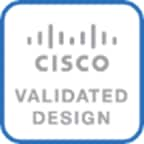
Table 1 lists the component models and versions used for solution validation in Cisco Labs. Other software and hardware combinations can also be used if it is supported in Cisco and VMware’s Hardware Compatibility Lists (HCL).
Table 1. Solution Components per Site
Solution Topology
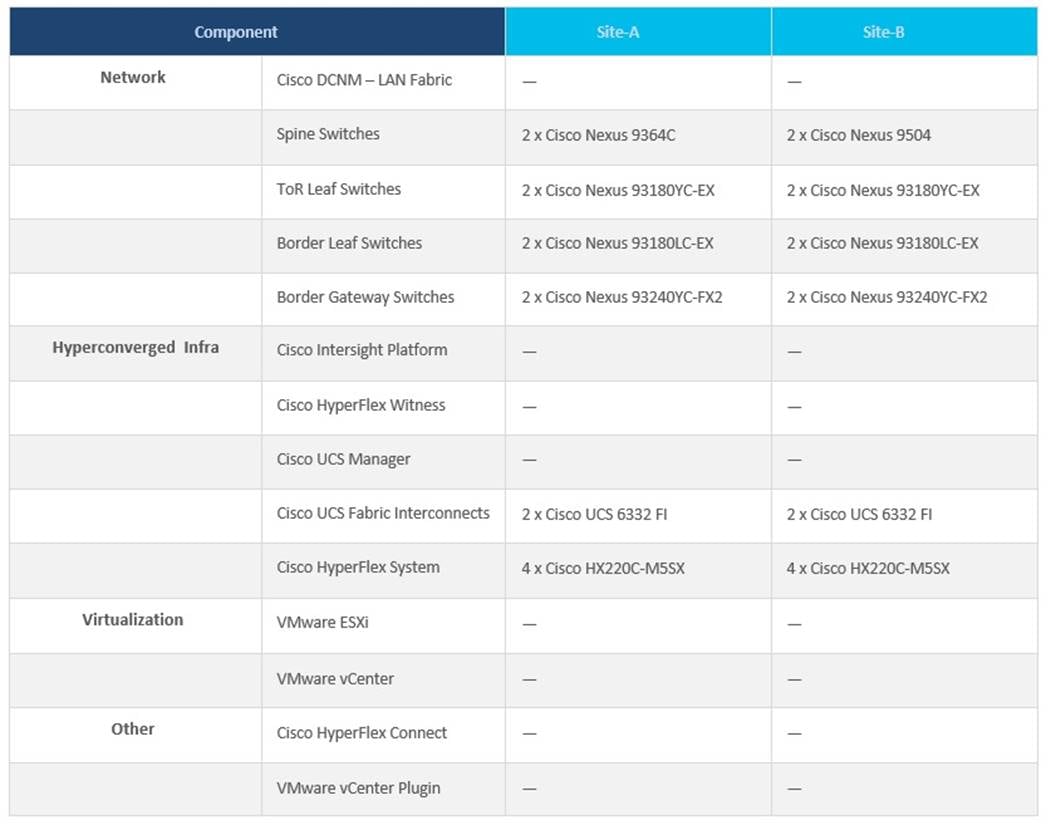
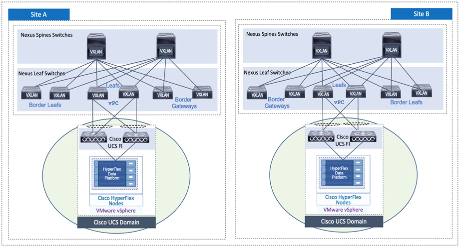
Figure 1 shows the high-level design for the solution using two active-active data center sites.
Figure 1. Solution Topology (High-level)
The Cisco HyperFlex Stretch Cluster with a VXLAN Multi-Site fabric solution is designed to address the following key requirements:
● Business continuity and disaster recovery in the event of a complete data center (site) failure
● Flexible, distributed workload placement with workload mobility across data centers
● Each site should be able to operate independently – no dependency on the other site
● Access to external networks and services directly from each site
● Site Affinity – a Virtual Machine (VM)’s data should be locally accessible under normal conditions
● Quick recovery with zero data loss if a failure occurs
● Simplified administration and operation of the solution
The solution also meets the following high-level design goals:
● Resilient design across all layers of the infrastructure with no single point of failure
● Scalable design with the ability to independently scale compute, storage, and networking as
needed
● Modular design with the ability to upgrade or replace components and sub-systems as needed
● Flexible design across all layers of the solution that includes sub-system design, individual
components used, and storage configuration and connectivity options
● Operational agility and simplicity through the use of automation and orchestration tools
● Incorporates technology and product best practices for the different components in the solution
This section provides a detailed overview of the network, compute, storage, and virtualization layer design used in the solution.
The data center network must first be in place before an Enterprise can deploy the HyperFlex VSI in the two active-active data centers. The design discussion will therefore begin with the network design used in the solution.
The network connectivity required to deploy and maintain a HyperFlex VSI in the two data centers are as follows:
● Reachability from Cisco HyperFlex Installer VM to the out-of-band management IP addresses on Cisco UCS Fabric Interconnects and HyperFlex servers in each data center.
● Reachability from Cisco HyperFlex Installer VM to the in-band management (ESXi) IP addresses on Cisco HyperFlex servers in each data center.
● Reachability from the HyperFlex Installer VM to infrastructure services needed to bring up the cluster. In this design, the HyperFlex Installer VM, Cisco HyperFlex Witness, and VMware vCenter are all located in a third site, separate from the active-active data center sites.
● Layer 2 or Layer 3 reachability from HyperFlex cluster nodes in each data center to the Cisco HyperFlex Witness and VMware vCenter used in the solution.
● Layer 2 in-band management and storage-data connectivity between Cisco HyperFlex cluster nodes distributed across the two active-active sites.
Network - Cisco VXLAN Fabric Design
The end-to-end data center network used in this solution is a Cisco VXLAN EVPN Multi-Site fabric. The VXLAN fabric provides a highly flexible, scalable, and resilient multi-site network architecture for enabling business continuity and disaster recovery in Enterprise data centers. The end-to-end VXLAN fabric consists of two VXLAN fabrics, one in each data center site, interconnected by an inter-site network. The VXLAN fabric in each data center is a 2-tier Clos-based spine and leaf architecture, built using Cisco Nexus® 9000 Series spine and leaf switches. Cisco Data Center Network Manager (Cisco DCNM) centrally manages the end-to-end, multi-site fabric. The fabric design is highly resilient, with no single point of failure, and incorporates technology and product best practices in the design.
VXLAN fabrics establish VXLAN overlays (tunnels) across an IP underlay to extend Layer 2 edge networks across a Layer 3 boundary (in this case, a routed data center network). The Layer 2 extension enables East-West communication between applications and services hosted in the data center that need Layer 2 adjacency. In this solution, the HyperFlex stretch cluster needs Layer 2 adjacency between all nodes in the cluster for intra-cluster communication to bring the cluster online and for the overall health and operation of the cluster.
Layer 2 extension also provides seamless mobility where application endpoints (MAC, IP) can move anywhere in the data center without requiring configuration changes. In this solution, the VXLAN Multi-Site fabric provides Layer 2 extension (and Layer 3 forwarding) with seamless mobility within the data center and between data centers. Seamless mobility is critical for disaster recovery as it enables application VMs to quickly failover and become operational in a second data center. For a HyperFlex stretch cluster, endpoint mobility enables a node in a second data center to take over as the cluster master using the same IP and continue providing data services from the second data center.
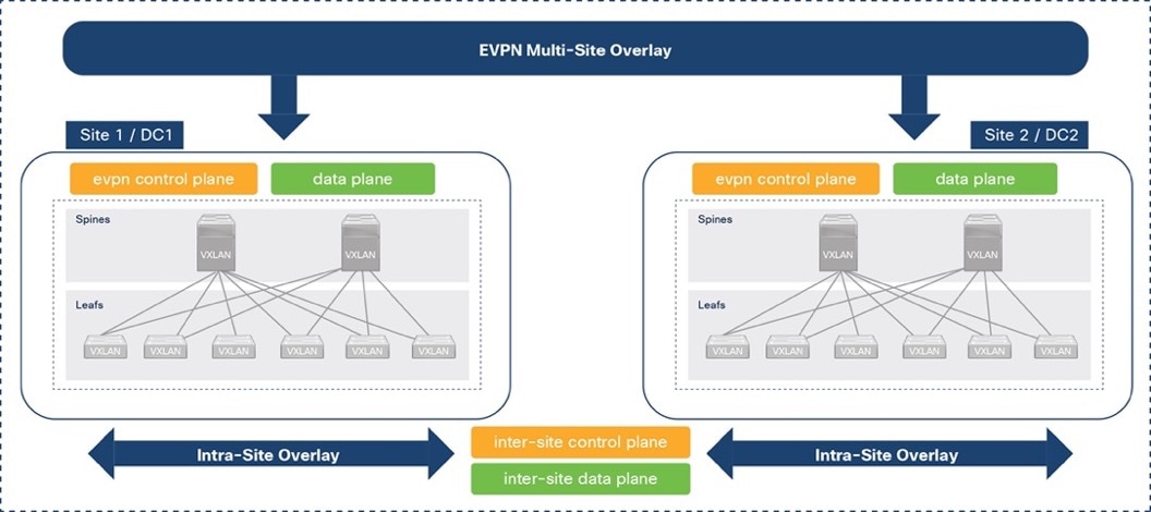
VXLAN overlays are commonly used in data centers due to the flexibility and functionality it provides, but it can also create a flat overlay network that spans data centers, with no fault isolation. VXLAN overlays also use a data plane flood-and-learn mechanism, similar to Ethernet, for address learning. When VXLAN overlays interconnect data centers, this can create a multi-data center, bridged overlay network, causing large amounts of traffic to be flooded across data centers. To address the problem, Internet Engineering Task Force (IETF) standardized a control plane mechanism for address learning using an Internet-scale routing protocol, Multi-Protocol Border Gateway Protocol (MP-BGP), and a new address family called Ethernet VPNs (EVPNs). VXLAN fabrics can use the MP-BGP EVPN address family to distribute endpoint reachability information (MAC, IP) and additional information such as the network and tenant (VRF) associated with the endpoint. This method not only reduces flooding but also enables optimal forwarding of traffic within a VXLAN fabric. MP-BGP also provides segmentation and fault isolation in the overlay without sacrificing Layer 2 extension or seamless mobility between data centers. Cisco’s VXLAN Multi-Site architecture uses MP-BGP to provide a more scalable architecture for interconnecting the active-active data centers in the solution. Figure 2 illustrates this architecture. For more details, see: https://www.cisco.com/c/en/us/products/collateral/switches/nexus-9000-series-switches/white-paper-c11-739942.html
Figure 2. VXLAN EVPN Multi-Site Architecture
Cisco DCNM Design
As stated earlier, Cisco DCNM serves as a centralized controller to provision and manage the VXLAN Multi-site Fabric in the solution. Cisco DCNM, though not required, is highly recommended for any VXLAN deployment with more than a few switches. Cisco DCNM is available in three modes: LAN Fabric, SAN, or IP Fabric for Media. Cisco DCNM in LAN Fabric mode is used in this solution. LAN Fabric simplifies the management of a VXLAN fabric and reduces the deployment time of a data center fabric from days to minutes. Cisco DCNM minimizes configuration errors by using policy templates that generates the configuration that gets deployed on the. Templates provide an error-free and scalable mechanism for deploying and maintaining configuration changes. To ensure configuration compliance, Cisco DCNM continuously monitors the switches and provides alerting with 1-click remediation to maintain consistency and prevent configuration drifts.
In the solution, Cisco DCNM is deployed as a cluster of multiple nodes for high availability (HA). Two Cisco DCNM virtual machines are deployed in native HA mode and operate as active/standby nodes. Additional compute nodes (or worker VMs) can be added for scalability; three worker VMs are used in this solution to support operational tools such as Cisco Network Insights. The VMs are hosted on three physical servers. The Cisco DCNM VMs and compute/worker VMs are clustered and must be in the same Layer 2 network on each ethernet interface (eth0, eth1, eth2).
Figure 3 shows the connectivity from Cisco DCNM to the VXLAN Multi-Site fabric in this solution.
Figure 3. Cisco DCNM Connectivity to VXLAN Fabric Switches
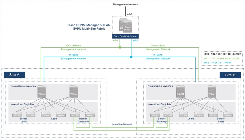
Cisco DCNM GUI is accessible from the management network on the eth0 interface of the VMs in the cluster. Cisco DCNM connects to the VXLAN fabric in each site through the out-of-band (OOB) management network on eth1 and has connectivity to all switches that it manages, including the Nexus 7000 series gateway switches used in the solution for external connectivity. Cisco DCNM uses an in-band (IB) management network on eth2 for bandwidth-intensive operations such as the Endpoint Locator and telemetry features. Cisco DCNM is not necessary for traffic forwarding; only for managing and provisioning the fabric.
Cisco DCNM also provides complete lifecycle management and automation, with capabilities such as automated fabric deployment, automatic consistency-checking, automatic remediation, and device lifecycle management. Cisco DCNM provides real-time health summary of the fabrics, devices, and topologies, with correlated visibility and triggered alarms. Cisco DCNM also offers numerous workflows for agility in operations (return materials authorization [RMA], install, upgrade) and deployment such as customizable Python++ templates for enabling access-layer, multi-site and external connectivity. All deployment history (underlay, overlay, interface) is also available on a per-switch basis. Cisco DCNM also has other features to simplify and speed up operations such as interface grouping, vPC peering using virtual links, auto peer matching of vPC peers for provisioning, and VMM workload automation. For a more complete list of features, see Cisco DCNM’s datasheet available here.
Fabric Automation and Agility
Cisco DCNM serves as a single point of automation for the end-to-end VXLAN Multi-Site fabric. Cisco DCNM offers multiple programmability options to automate and achieve the agility that Infrastructure as Code (IaC) can provide. Cisco DCNM provides RedHat Ansible modules, HashiCorp Terraform providers, and Representational State Transfer (REST) APIs to provision and manage a VXLAN Multi-Site fabric. Cisco DCNM is also a single point of integration, northbound to DevOps and other IT toolsets.
In this solution, Cisco DCNM Fabric Builder provides Day-0 automation for deploying the end-to-end VXLAN Multi-Site fabric and Cisco DCNM Terraform provider for Day-2 automation. Terraform plans automate Day-2 deployment activities such as adding a new leaf switch pair, provisioning access layer connectivity to Cisco UCS FI and HyperFlex VSI, adding tenants, and adding networks. The Fabric Builder deploys a greenfield VXLAN Fabric in each site and provides templates for additional connectivity such as connectivity to outside/external networks, including the configuration of external gateways outside the fabric. Fabric Builder also provisions the multi-site fabric to enable connectivity between the two data center site fabrics. Cisco DCNM uses policy-based Python++ templates for provisioning that incorporates technology and product best practices where possible.
Figure 4 shows the Cisco DCNM Fabric Builder templates used in this solution to automate the deployment of the end-to-end VXLAN Multi-site fabric.
Figure 4. Cisco DCNM LAN Fabric – Fabric Builder Templates
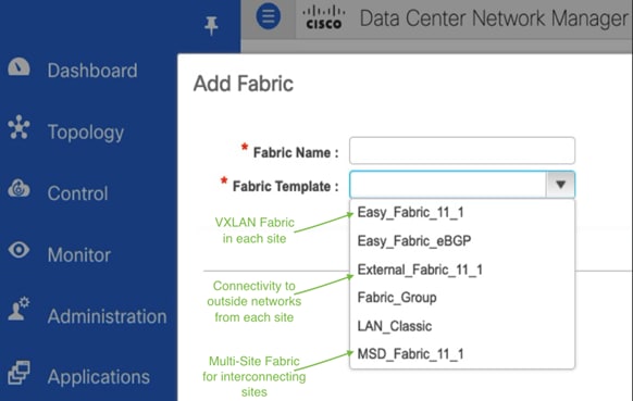
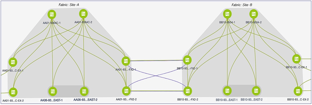
Figure 5 shows the end-to-end VXLAN EVPN Multi-Site fabric deployed by the Fabric Builder templates above. This fabric was used to validate the active-active data center solution in Cisco Labs.
Figure 5. VXLAN EVPN Multi-site Fabric
VXLAN Fabric – Intra-Site Design
In the active-active data center solution, each data center site has an independent VXLAN fabric, built using Cisco Nexus 9000 Series switches in a 2-tier, spine-leaf Clos topology. The intra-site design is highly resilient, with no single point of failure. Cisco DCNM manages the site fabrics as well as the end-to-end multi-site fabric.
Figures 6 and 7 illustrate the intra-site design for the two data centers (Site-A, Site-B) used in the solution.
Figure 6. Intra-Site Design – Data Center Fabric in Site-A
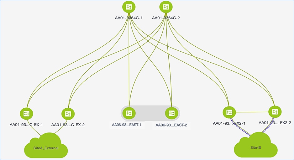
Figure 7. Intra-Site Design – Data Center Fabric in Site-B
The site fabric design in the two active-active data center sites is very similar. Each site uses a two-tier Clos topology consisting of a pair of spine switches and three pairs of leaf switches. The spine switches provide high-speed core connectivity and serve as redundant Internal Border Gateway Protocol (iBGP) route-reflectors (RR) and as IP Multicast Rendezvous-Points (RP) for each site fabric. The leaf switch pairs provide different functionality depending on its role. The three Leaf switch pairs deployed in each site are:
● Access/ToR Leaf switches for connecting to Cisco UCS and HyperFlex infrastructure in each site
● Border Leaf switches for connecting to outside/external networks from each site
● Border Gateway Leaf switches for inter-site connectivity between data centers
For scalability, this design uses separate leaf switch pairs for each role. However, smaller deployments can combine the switch roles and use fewer leaf switch pairs if necessary. The leaf switches are dual-homed to the two spine switches and do not connect directly to other leaf switches. However, border gateway switches connect directly for inter-site connectivity to establish full-mesh E-BGP connectivity between sites. Cross-links minimize the need for the more costly inter-site links. For more details on this design, see VXLAN EVPN Multi-Site Design and Deployment White Paper.
In this solution, the VXLAN fabric is deployed in each site using the Easy_Fabric_11_1 template available in Cisco DCNM Fabric Builder. The template will automate the Day 0 provisioning of the VXLAN fabric in each data center site using the inputs specified by the fabric administrator in Cisco DCNM. The specified inputs, both mandatory and optional, can be broadly grouped as outlined below.
● Underlay Networking – for example, BGP, Anycast GW MAC, Interface Numbering, etc.
● Layer 2 Multi-Destination Traffic handling, replication mode and related configuration
● Underlay Routing Protocols – for example, Intermediate System-to-Intermediate System (S-IS), Open Shortest Path First (OSPF), or Exterior Border Gateway Protocol (eBGP)
● Advanced Configuration (QoS, Encryption, Fabric MTU, Overlay VRF/Network Templates)
Underlay Network
This section is used to provide general information regarding the underlay such as the BGP Autonomous System Number (ASN) for each site, the interface type (point-to-point, unnumbered) and subnet mask (/30, /31) on the interfaces, the underlay routing protocol (OSPF, ISIS) etc.
In the active-active data center design, both site fabrics use the same configuration except for the BGP ASN for each site. The underlay links are point-point IPv4 links with a /30 subnet mask and use OSPF as the underlay routing protocol. All links in the fabric also use jumbo MTU.
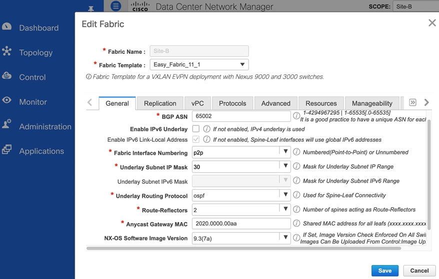
Figure 8 and Figure 9 shows the underlay settings in Site-A and Site-B respectively, configured using the Easy_Fabric_11_1 template.
Figure 8. Fabric Builder: Underlay Configuration (Site-A)
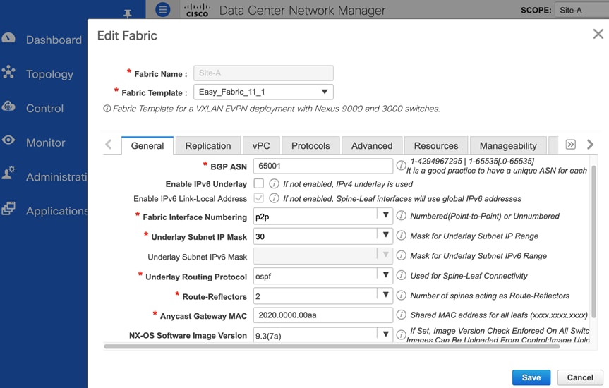
Figure 9. Fabric Builder: Underlay Configuration (Site-B)
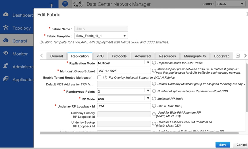
Replication
Ethernet networks use flooding to forward broadcast, unknown (yet-to-be learned destinations) unicasts and multicast (BUM) traffic to endpoints in the same Layer 2 broadcast domain. When the Ethernet networks span a VXLAN fabric, the fabric can use either IP Multicast or Ingress Replication to forward the BUM traffic. A local VXLAN Tunnel Endpoint (VTEP) or Leaf switch will forward the BUM traffic it receives to all remote VTEPs handling traffic for that Ethernet segment. If the fabric uses Ingress (headend) Replication, the local VTEP will replicate and send an individual copy to each remote VTEP. If the fabric uses IP Multicast, the local VTEP will forward it to the IP Multicast group associated with that network. In a VXLAN fabric, each Ethernet network is assigned an IP multicast group for sending and receiving BUM traffic. When the administrator deploys a Layer 2 or Layer 3 network on a VTEP, the VTEP will use Internet Group Management Protocol (IGMP)/Protocol Independent Multicast (PIM) to join the multicast group associated with that network. Cisco recommends using IP multicast for forwarding BUM traffic efficiently across an IP underlay network. This design uses IP multicast.
When using IP multicast, a multicast routing protocol, either PIM-ASM or PIM-BiDir, is needed. Both protocols also use a Rendezvous-Point (RP), and the spine switches in each fabric are ideal for providing this functionality as it is centrally located with connectivity to all leaf switches in the fabric. In this solution, both data center sites use IP multicast with PIM-ASM for BUM forwarding, with the spine switches serving as redundant RPs for each fabric. Cisco DCNM Fabric Builder automatically provisions the configuration necessary to enable IP multicast for BUM forwarding. Figure 10 shows the replication settings used in Site-A, configured using the Easy_Fabric_11_1 template. An identical configuration is used in Site-B. The two sites can also use different replication modes if needed.
Figure 10. Fabric Builder: Replication Configuration (Site-A)
As each network is provisioned, an IP multicast group address must also be provisioned for forwarding BUM traffic. As the number of Layer 2 segments increase, the number of multicast groups and forwarding states that must be maintained also increases. By default, Cisco DCNM uses the same IP Multicast group address for all networks unless explicitly specified otherwise. Using the same multicast group reduces the control plane resources used, but it also means that a VTEP could receive BUM traffic for a network that it does not handle. The VTEP will forward the BUM traffic to a local segment only if the VXLAN Network ID (VNID) on the packets matches that of the local segment. Nevertheless, in this solution, each HyperFlex infrastructure network is assigned a separate Multicast IP group to make it easier to monitor and troubleshoot.
For BUM forwarding between data centers, see “Inter-site Design – Interconnecting Data Centers” section of this document.
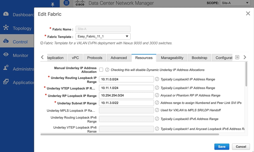
Protocols
A VXLAN fabric uses routing protocols to advertise VTEP and endpoint reachability (or address learning. In this solution, OSPF and BGP are used. Cisco DCNM Fabric Builder deploys multiple loopbacks for use as router ID by the routing protocols, as tunnel endpoint IP, for vPC peering and so on.
Figure 11 and 12 show the settings used in Site-A.
Figure 11. Fabric Builder: Underlay Protocols Configuration (Site-A)
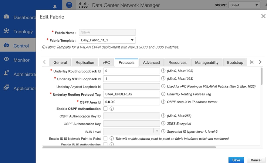
Figure 12. Fabric Builder: Underlay Resources Configuration (Site-A)
Additional Considerations
This section discusses additional factors to consider when deploying a VXLAN EVPN fabric:
● VXLAN fabrics can use a data-plane flood-and-learn mechanism, similar to Ethernet, for address learning and endpoint reachability. The flooding is done using either IP Multicast or Ingress Replication. Though IP Multicast is efficient, large amounts of multicast traffic can still limit the scalability of a data center fabric. Alternatively, a more scalable, control-plane method using MP-BGP EVPN can also be used for address learning. By default, Cisco DCNM Fabric Builder deploys VXLAN fabrics using MP-BGP EVPN.
● Cisco VXLAN fabrics use MP-BGP to advertise endpoint reachability, specifically internal BGP (iBGP) within a site and external BGP (eBGP) between sites. For iBGP, the switches must have full-mesh connectivity or peer with Route-Reflectors (RRs) that can relay the routes. By default, Cisco DCNM deploys route-reflectors deployed on spine switches since all leaf switches connect to it.
● When an endpoint originates an ARP request, the receiving VTEP or Leaf switch will flood the ARP broadcast to all VTEPs in the fabric using the multicast-group address associated with that network. However, if ARP Suppression is enabled, the receiving VTEP will first inspect the ARP request and if it has learned the endpoint info via MP-BGP EVPN, it will respond to the ARP request locally. ARP suppression is only supported for Layer 3 networks.
● In VXLAN fabrics, the Integrated Routing and Bridging (IRB) provided by leaf switches can be symmetric or asymmetric. Symmetric IRB is more scalable and less complex from a configuration perspective. By default, Cisco DCNM deploys symmetric IRB.
● Distributed anycast gateways facilitate flexible workload placement and endpoint mobility across a data center fabric. In a VXLAN fabric, each Leaf switch is a distributed anycast gateway for the Layer 3 networks connected to it. All leaf switches configured for a given Layer 3 network will use the same gateway IP and virtual MAC address (2020.0000.00aa), ensuring that the endpoint always has a valid ARP entry for its gateway, regardless of where it moves to within the data center. For each Layer 3 network provisioned, Cisco DCNM will automatically deploy the corresponding anycast gateway function on all relevant switches in the end-to-end VXLAN Multi-Site fabric.
● VXLAN fabrics with MP-BGP EVPNs use multi-tenancy concepts similar to that of MPLS Layer 3 VPNs. When advertising routes to other BGP peers, Route Distinguishers (RD) ensure the global uniqueness of routes from different VPNs (VRFs). Route targets (RT) enable flexible route export/import on a per-tenant/VRF basis. In the data plane, VXLAN uses VNIDs to segment the overlay network by mapping each edge network to a VXLAN segment (VNID) and by enforcing VNID/VRF boundaries. In this solution, multi-tenancy separates the infrastructure connectivity from that of the applications hosted on the infrastructure. The design uses an infrastructure tenant (HXV-Foundation) for all connectivity required to build and maintain the HyperFlex VSI and an application tenant for the applications hosted on the HyperFlex VSI. For each VRF provisioned, Cisco DCNM will automatically deploy the corresponding tenancy configuration on all relevant switches in the VXLAN Multi-Site fabric. Enterprises can choose a tenancy model that meets the needs of their business.
● VXLAN uses a MAC-in-IP/User Datagram Protocol encapsulation, resulting in a 50B overhead on VXLAN-tagged frames. A VTEP (leaf) also cannot fragment the packets per the IETF standard. For this reason, the fabric MTU should at least be 50B higher than the largest packet it can receive from an endpoint. By default, Cisco DCNM uses an MTU of 9216B.
● VNID allocation and naming conventions: The VXLAN fabric deployed in this design uses VNIDs in the 20000s range for Layer 2 networks and 30000s range for Layer 3 networks.
Similarly, the design uses a naming convention such as “<NameOfObject>_<Type>” where Type indicates the type of object (for example, Mgmt_VLAN). Enterprises can use a similar approach as it can be helpful from a troubleshooting perspective.
Intra-Site Design – Core Connectivity
Core connectivity refers to the connectivity between spine and leaf switches within a given data center site. As stated earlier, the VXLAN fabric in each site is a collapsed, 2-tier Clos-based spine and leaf topology, where each leaf switch connects to all spine switches in the top-tier. Clos topologies are designed for modern applications that are increasingly distributed, resulting in large amounts of East-West traffic in today’s data centers. Clos topology provides a simple and scalable design, with predictable latency and performance to meet the needs of modern data centers. Clos topologies provide multiple equal-cost paths that the VXLAN fabric can leverage for load-balancing East-West traffic. Clos fabrics also offer predictability and consistency where connectivity between any two endpoints is always three hops (leaf-spine-leaf). The fabric can also be easily scaled by adding more leaf and spine switches to the topology.
In this solution, the VXLAN fabric in each site consists of a pair of spine switches and three pairs of Leaf switches, built using Cisco Nexus 9000 series switches. The Solution Validation section of this document provides the specific Cisco Nexus switch models used in the solution. The design uses 40GbE links for core connectivity and 10GbE links for external and inter-site connectivity. The design ensures that each site can operate independently of the other in the event of a failure, and provides access to outside networks and services directly from each site.
Intra-Site Design – Edge Connectivity
Leaf switches use Link Aggregation Control Protocol (LACP) to bundle links that connect to physical and virtual endpoints in the edge network. Link aggregation provides redundancy and higher aggregate bandwidth. A port-channel or a virtual Port-Channel (vPC) can be used but vPCs are preferred when possible as it also provides node-level resiliency.
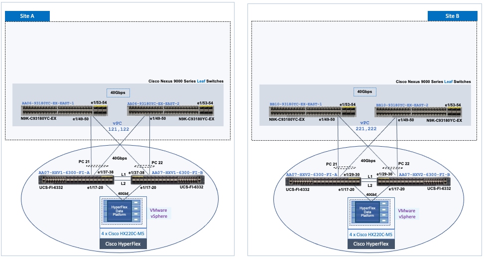
In this solution, leaf switches use vPCs to connect to the Cisco UCS domain (and HyperFlex infrastructure) in each site as shown in Figure 13. Leaf switches are deployed as Virtual Port-Channel (vPC) peers and use 40GbE links for connecting to the Cisco UCS FIs. The vPC design is identical in both active-active data center locations.
Figure 13. Intra-Site Design: Edge Connectivity in Site-A and Site-B
Intra-Site Design – Outside/External Connectivity
Endpoints and applications that connect to the VXLAN fabric require access to networks and services outside the fabric. In this solution, external connectivity is necessary for deploying and managing the HyperFlex VSI. The fabric must provide connectivity to the HyperFlex Installer, HyperFlex Witness, and VMware vCenter located outside the fabric. Applications hosted on the HyperFlex VSI also require access to outside networks and services. In this design, both sites have dedicated connections for external connectivity, enabling each site to operate independently in the event of failure in the other. Figure 13 shows a high-level view of the external connectivity in each site (Site-A, Site-B) to the external gateways outside the fabric (SiteA_External, SiteB_External).
Figure 14. External Connectivity in Site-A and Site-B (High Level View)
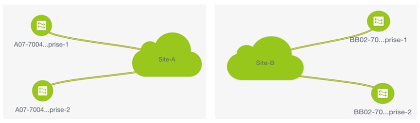
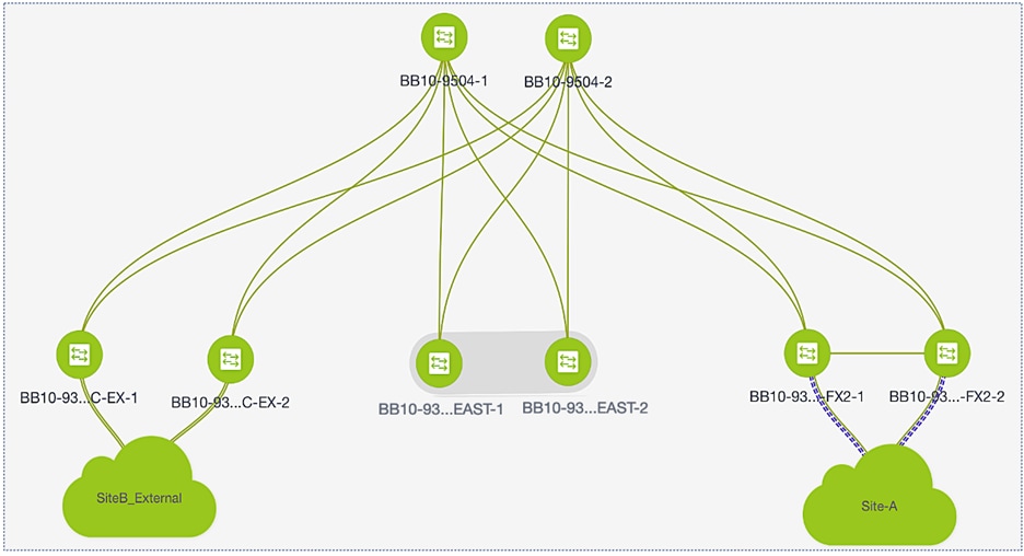
Figure 15 shows the detail external connectivity in each site.
Figure 15. External Connectivity in Site-A and Site-B (Detailed View)
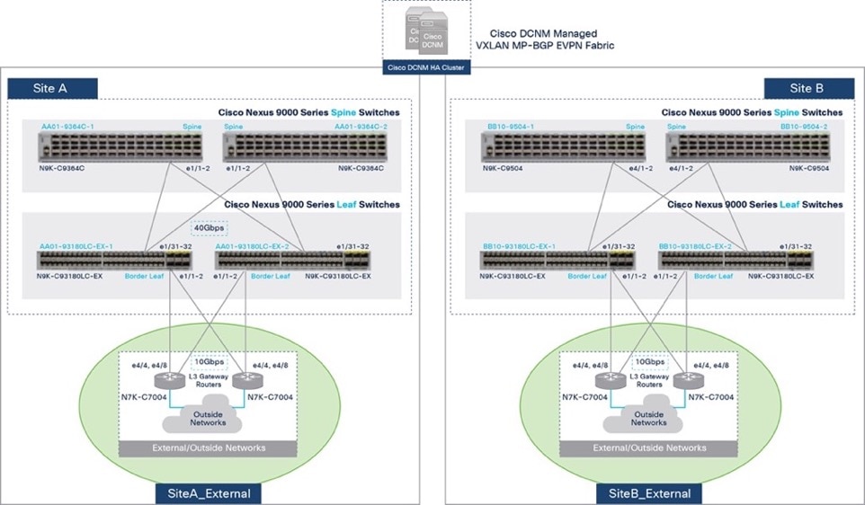
The design uses a pair of Cisco Nexus 7000 Series switches as external gateways in the outside network that connect to the border leaf switches in Site-A and Site-B fabrics using redundant 10 GbE links.
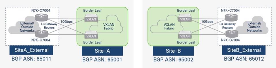
Cisco VXLAN fabrics can connect to outside/external networks using a VRF-to-VRF handoff, either to an MPLS-VPN or IP network, or use VRF-to-IP network handoff. This solution uses VRF-to-VRF handoff to an IP network which extends the multi-tenancy to the external IP network. The design uses MP-BGP to enable this connectivity and extend multi-tenancy (VRFs) to the external network. The VXLAN fabrics in each site and the external networks are all in different BGP Autonomous Systems as shown in Figure 16.
Figure 16. MP-BGP External Connectivity in Site-A and Site-B
Figures 17 and 18 show the Cisco DCNM Fabric Builder configuration for external connectivity from Site-A and Site-B respectively. This configuration is part of the Easy_Fabric_11_1 template.
Figure 17. Cisco DCNM Fabric Builder – External Connectivity (Site-A)
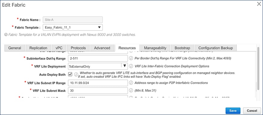
Figure 18. Cisco DCNM Fabric Builder – External Connectivity (Site-B)
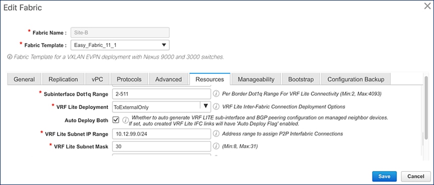
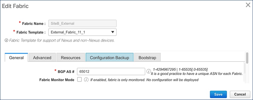
Cisco DCNM can also manage the external network, either in managed or monitored mode. In this solution, the external network is in managed mode which enables Cisco DCNM to provision the VRF-Lite setup on the external gateways. Cisco DCNM Fabric Builder uses the External_Fabric_11_1 template to deploy the external network and establish connectivity from the external gateways to the border leaf switches in each site.
Figures 19 and 20 show the corresponding Cisco DCNM Fabric Builder configuration for external networks (SiteA_External, SiteB_External) that connect to Site-A and Site-B respectively.
Figure 19. Cisco DCNM Fabric Builder – External Network Setup (Site-A)
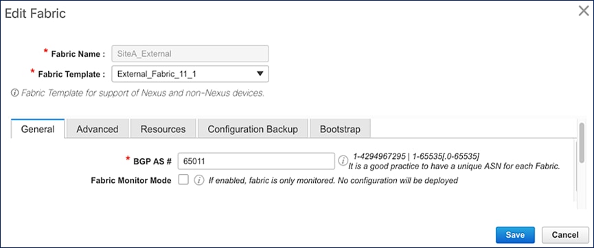
Figure 20. Cisco DCNM Fabric Builder – External Network Setup (Site-B)
The access-layer connectivity from each site to the external gateways is enabled through Inter-Fabric links configured for IEEE 802.1Q trunking. For high availability, each border leaf switch connects to both external gateways in a full-mesh topology. Each connection is from a routed, VLAN tagged, VRF interface on the border leaf switch to a routed, VLAN tagged VRF-Lite interface on the external gateway. The Layer 3 connectivity is on a per VRF basis, enabled only for tenants that require connectivity to external/outside networks. In this design, the HXV-Foundation_VRF requires external connectivity (Layer 3) from both sites.
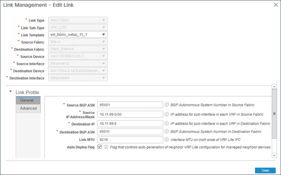
Figure 21 shows the Inter-Fabric connectivity between switches in Site-A and SiteA_External. Cisco DCNM Fabric Builder automatically provisions the links using the ext_fabric_setup_11_1 policy. The setup in Site-B is similar to that of Site-A – IP addressing and BGP ASN are different.
Figure 21. Cisco DCNM Fabric Builder – Site-A External Connections
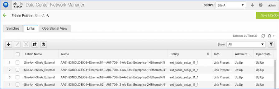
Figure 22 shows the detailed link-level configuration for one link between the VXLAN fabric and external fabric in Site-A. The remaining links in Site-A and Site-B links are set up similarly.
Figure 22. VXLAN Fabric and External Fabric Site A – Detailed Configuration
When the external-facing links and the initial setup is complete as previously described, the tenants and VRF interfaces for the HyperFlex infrastructure connectivity or for applications hosted on the HyperFlex infrastructure can be deployed as needed on the border leaf switches to enable external connectivity for those tenants.
Inter-Site Design – Interconnecting Data Centers
The VXLAN EVPN Multi-Site architecture provides seamless Layer 2 and Layer 3 extension between individual VXLAN EVPN fabrics. Inter-site (or data center) connectivity is possible using different Data Center Interconnect (DCI) technologies; however the VXLAN EVPN Multi-Site approach is a more integrated and scalable architecture. For more details about the Multi-Site approach used in this design, refer to the IETF drafts listed in the References section of this document.
The Inter-Site network provides the Layer 3 connectivity between VXLAN fabric sites in a VXLAN EVPN Multi-Site architecture. In this solution, Border Gateways (BGWs) in the active-active sites directly connect to each other to enable east-west traffic flow between data centers. In Cisco VXLAN fabrics, you can deploy BGWs as standalone leaf switches or combine the function with spine switches already in each site. BGW function can also be combined with the Border leaf switches that provide connectivity to outside networks and services. This design uses standalone BGW leaf switches for a more scalable design to support large Enterprise data centers. The BGWs can be deployed as vPC Gateways or Anycast BGWs. vPC Gateway mode is used when BGWs connect to endpoints, typically network services such as firewalls and load balancers. Anycast BGW mode is used when there are no endpoints directly connecting to them. In this design, BGWs are deployed in Anycast BGW mode. At the time of writing this document, Enterprises can deploy up to four BGWs in each site for higher data-plane scalability. The solution uses two BGWs per site, but you can add additional BGWs as needed.
The BGWs provide separation between the internal VXLAN fabric and the external or inter-site VXLAN network by implementing internal and external VTEP functions for connecting to the internal and external networks respectively. To the internal fabric, the BGWs in a site are anycast BGWs (A-BGWs); they provide a common anycast virtual IP (VIP) address that is used for all data-plane communication between sites. A dedicated loopback IP address is allocated for this VIP. The distributed BGWs with anycast VIP enable you to use Equal Cost Multi-Pathing (ECMP) to provide active data forwarding across all BGWs for load distribution and redundancy.
To enable BUM traffic forwarding between sites, BGWs use ingress replication. However, within a site, Enterprises can use either IP multicast or ingress replication, and it can be different in each site. This design uses IP Multicast with PIM ASM within each site. In the VXLAN EVPN Multi-Site architecture, a BGW is elected as the designated-forwarder for each Layer 2 VNI. The election process distributes the designated-forwarder functionality for the different networks across the different A-BGWs. The A-BGWs will forward BUM traffic for one or more networks typically. Failure detection and the failover of VIP and designated-forwarder function to other BGWs is an important advantage of the VXLAN EVPN Multi-Site architecture. Internal and external interfaces on the BGWs are specially configured to understand their role in the network and tracked to detect failure quickly. Seamless Layer 2 and Layer 3 extension between sites will be available as long as one BGW with one internal- and external-facing interface is available in each site.
The control plane for inter-site connectivity uses Multiprotocol External BGP (MP-eBGP), unlike intra-site connectivity, which can use either eBGP or iBGP. For control-plane scalability, you can deploy route servers in the inter-site network and provide the functions similar to route reflectors in iBGP. Route servers are recommended when three or more sites are being connected. Route servers are not used in this solution because it is an active-active, two-data-center solution. However, not using a centralized entity for route peering means that the BGWs in one site will need full-mesh eBGP connectivity to BGWs in the remote site.
The EVPN Multi-Site architecture uses VXLAN tunnels to provide Layer 2 extension and Layer 3 forwarding. VXLANs add 50 - 54 bytes of overhead, so a minimal MTU of 1550 or 1554 is necessary in the inter-site network. In this design, a jumbo MTU of 9216 is used in the end-to-end VXLAN fabric, including the inter-site network.
Figure 23 shows the high-level inter-site design with back-to-back gateways used in this solution.
Figure 23. Inter-Site Design with Back-to-Back Border Gateways
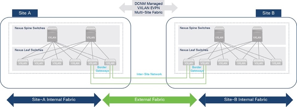
![]() The anycast BGWs in each site are also directly connected to each other using a cross-link, resulting in a square topology in the inter-site network. The IP connectivity provided by the square topology is necessary for proper BUM traffic handling.
The anycast BGWs in each site are also directly connected to each other using a cross-link, resulting in a square topology in the inter-site network. The IP connectivity provided by the square topology is necessary for proper BUM traffic handling.
In this solution, Cisco DCNM deploys and manages the inter-site connectivity. Cisco DCNM Fabric Builder deploys a multi-site domain (MSD) fabric using the MSD_Fabric_11_1 template, and the existing fabrics (Site-A, Site-B, SiteA_External, SiteB_External) are then added and integrated into this new MSD fabric with Cisco DCNM managing the end-to-end network.
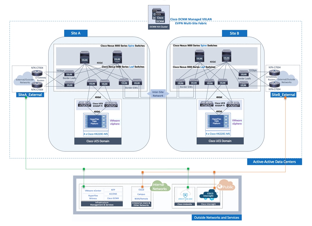
Figure 24 shows the physical connectivity between sites in the end-to-end MSD fabric.
Figure 24. Inter-Site Design – Physical Connectivity
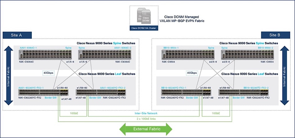
The border gateways used in this solution are a pair of Cisco Nexus 93240YC-FX2 Switches. The connectivity between the BGWs within a given site and across sites are 10-GbE, enabling BGWs to establish full-mesh eBGP sessions across all BGWs in the inter-site network. Within a site, BGWs connect to spine switches using 40-GbE links, the same as other leaf switches in each fabric.
The BGW is a point of transition from the intra-site to inter-site fabric, making it a good location for enforcing policies (QoS, security) between data centers. It may also be a transition point between higher and lower speed links where congestion can occur, so it is important to ensure that critical traffic is prioritized. The traffic across the inter-site links should be monitored to understand the traffic patterns and collect data baseline information such as the bandwidth consumed, and latency (peak, average) experienced by the flows traversing the inter-site links. The baseline collected can be a point of a reference for comparison purposes so that you can take corrective action before any performance issues occur. This monitoring is particularly important for the high-bandwidth, latency-sensitive storage flows that traverse these links. The actions you could take include adding more links to increase the available bandwidth and thereby avoiding congestion altogether or using QoS to prioritize the more critical storage traffic.
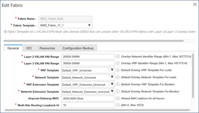
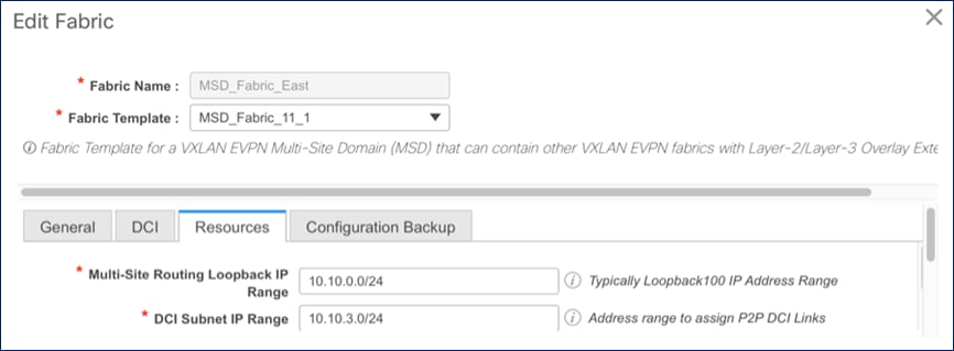
The following figures show the MSD fabric configuration deployed by Cisco DCNM for inter-site connectivity.
Figure 25. MSD Fabric - VNI range and Templates
For Inter-fabric connectivity, Direct_To_BGWS is selected to reflect the back-to-back BGW design used in this solution.
Figure 26. MSD Fabric - DCI Configuration
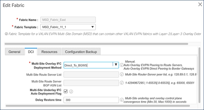
Figure 27. MSD Fabric - Resources Configuration
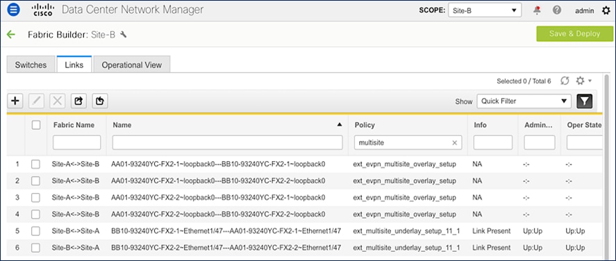
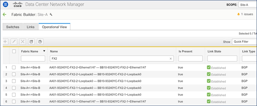
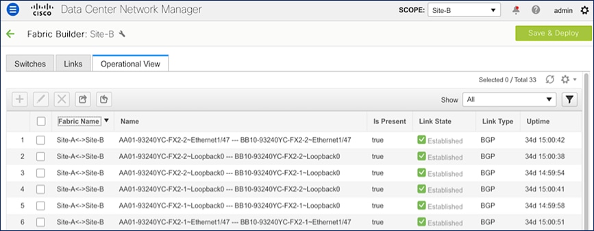
The inter-site connectivity between sites is setup by deploying the ext_multisite_underlay_setup_11_1 and ext_evpn_multisite_overlay_setup policies on the physical and loopback interfaces used for inter-site connectivity. Two 10-GE links (from e1/47 on each BGW) provide connectivity between sites and form the underlay IP transport for the inter-site network. The loopbacks are used to establish VXLAN overlay connectivity between sites. The following screenshots show the connectivity and policies used between sites in this solution.
Figure 28. Inter-Site Network: Overlay and Underlay Connectivity Setup (Site-A)
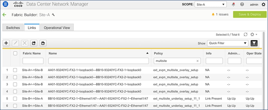
Figure 29. Inter-Site Network: Overlay and Underlay Connectivity Setup (Site-B)
The result of the configuration shown above is the following eBGP sessions getting established between BGWs:
Tenancy Design
The VXLAN MP-BGP EVPN is designed for multitenancy. The tenancy design can be along organizational or functional lines or based on other factors. The tenancy design in this solution is based on connectivity requirements. Two tenants are used in this design: HXV-Foundation_VRF and HXV-Application_VRF. The HXV-Foundation_VRF tenant is used for all HyperFlex infrastructure connectivity. It includes the connectivity required to stand up the virtual server infrastructure within and across data center sites. It also includes connectivity required by management and operational tools that manage the infrastructure. The application tenant, on the other hand, is for any application workloads hosted on the HyperFlex virtual server infrastructure. Enterprises can deploy additional tenants as needed to meet the needs of their deployment.
Connectivity to HyperFlex Infrastructure
The HyperFlex infrastructure networks are critical for the operation of the HyperFlex stretch cluster and the VMware vSphere cluster. To provide reachability for these networks through the VXLAN fabric, the VXLAN fabric must be first provisioned. The VXLAN fabric in each site also needs connectivity to the Cisco UCS domain where the HyperFlex nodes and ESXi hosts in the cluster reside. As described in the “Intra-Site Design — Edge Connectivity” section of this document, vPCs are used for connecting the HyperFlex infrastructure in the edge or access-layer network to the leaf switches in the VXLAN fabric. To enable connectivity beyond the leaf switches, the VXLAN fabric will need to extend the infrastructure networks across the inter-site network. In this design, all infrastructure connectivity is handled within a dedicated tenant ( HXV-Foundation_VRF), to keep the application and infrastructure connectivity (and traffic) separated.
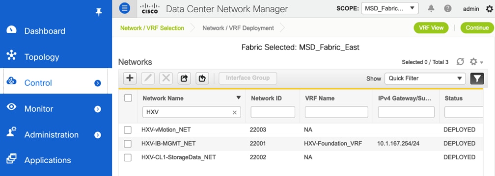
The HXV-Foundation_VRF in the VXLAN fabric enables connectivity for the following HyperFlex infrastructure networks:
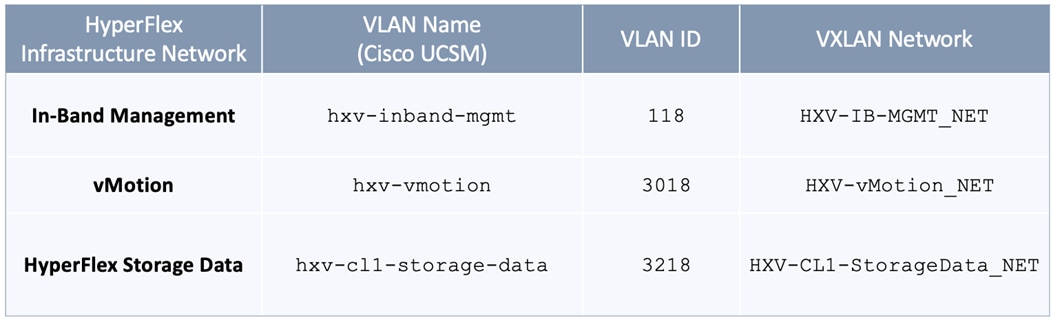
● In-band Management: This network is primarily used by HyperFlex nodes and ESXi hosts in the cluster for intra-cluster communications. The HyperFlex inband management network is mapped to the HXV-IB-MGMT_NET network within the VXLAN fabric to enable traffic forwarding and connectivity between endpoints on that network. This network is deployed as a Layer 3 network with the default gateway in the VXLAN fabric.
● Storage Data Network: This network is primarily used for HyperFlex storage cluster communication, for providing storage services and for accessing datastores hosted on the HyperFlex stretch cluster. The HyperFlex storage data network is mapped to the HXV-CLI1-StorageData_NET network within the VXLAN fabric to enable traffic forwarding and connectivity between endpoints on that network. This network is deployed as a Layer 2 network in the VXLAN fabric.
● VMware vMotion network: To support VMware vMotion for the virtual machines hosted on the HyperFlex VSI, ESXi hosts need connectivity to a VMware vMotion network. The HyperFlex vMotion network is mapped to the HXV-vMotion_NET network within the VXLAN fabric to enable traffic forwarding and connectivity between ESXi hosts in the cluster. It is deployed as a Layer 2 network in the VXLAN fabric.
![]() All provisioning is done using a combination of Cisco DCNM and HashiCorp Terraform automation. Cisco DCNM is used for Day 0 deployment and Terraform for Day 1 and Day 2 provisioning using the Terraform provider for Cisco DCNM
All provisioning is done using a combination of Cisco DCNM and HashiCorp Terraform automation. Cisco DCNM is used for Day 0 deployment and Terraform for Day 1 and Day 2 provisioning using the Terraform provider for Cisco DCNM
Figure 30 shows the HyperFlex Infrastructure networks provisioned in the VXLAN fabric for this solution.
Figure 30. HyperFlex Infrastructure Networks
The access layer connectivity to the UCS domain where the HyperFlex nodes reside is shown in Figure 31.
Figure 31. Access Layer Connectivity Design - To Cisco UCS Domain
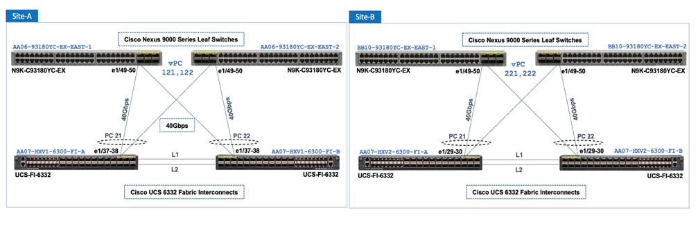
Figure 32 shows the corresponding VXLAN fabric side configuration to enable access-layer connectivity to the HyperFlex and Cisco UCS infrastructure in the access/edge network for Sites A and B, respectively. Note that vPCs 121-122 connect to FI-A and FI-B respectively in Site-A. Similarly, vPCs 221-222 connect to FI-A and FI-B respectively in Site-B.
Figure 32. Access-layer Connectivity to HyperFlex and Cisco UCS Infrastructure
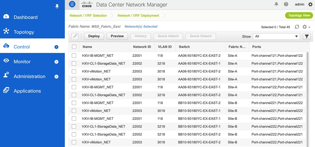
Each of the HyperFlex Infrastructure network (see Table 2) is trunked on the port-channel between the Cisco UCS domain and VXLAN Leaf switches in each site. The VLANs are mapped to the corresponding network in the VXLAN fabric – see Table 2. Note that the HyperFlex Infrastructure networks are part of the HXV-Foundation_VRF Tenant.
Table 2. HyperFlex Infrastructure Network
Connectivity for Applications and Services Hosted on HyperFlex VSI
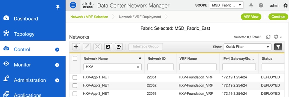
Once the HyperFlex cluster is up and running, applications can be deployed in either of the two active-active data centers. In this design, the connectivity for the application networks through the VXLAN fabric, is handled in one Application Tenant (HXV-Application_VRF). Customers can choose to use one Application Tenant for all their applications or choose a different tenancy model that best suits their needs. In this design, for validation, the following application tenants and networks were deployed.
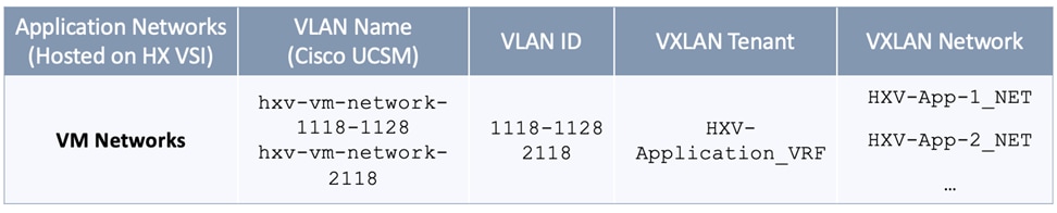
The Application Network VLANs are trunked on the same vPCs as the HyperFlex Infrastructure networks to connect to the application virtual machines that use these networks. Application VMs are hosted on the HyperFlex VSI. The configuration is identical in both sites to ensure that the applications can failover to the second site in the event of a failure in the first site.
High Availability
High availability is a critical consideration for any data center infrastructure design, and more so for a disaster-recovery solution such as this one. The active-active VSI in each data center delivers continuous access to mission-critical workloads, with each site providing backup and seamless failover for instances of failure. You can deploy applications and services in either data center location using local resources (HyperFlex VSI) or remote resources, depending on the type of failure. To achieve availability at the data center level, the sub-systems that make up data center infrastructure (compute, storage, network, virtualization) must provide complementary capabilities in each active-active data center, with the ability to fail over to the second data center if a failure occurs in the first one. High availability is also important within a data center to handle smaller failures with minimal impact.
For the network sub-system, the VXLAN EVPN Multi-Site architecture used in this solution provides the network fabrics in each data center location and the connectivity between them, as well as the ability to fail over by extending connectivity and services across data centers. The solution also provides high availability for the network fabric in each data center and in the inter-site network between them, with no single points of failure. The end-to-end network is resilient at the physical link and node level as well as across higher layers of the infrastructure stack. The high availability features the network provides include:
● VXLAN Multi-Site architecture: The architecture fundamentally provides high availability by enabling interconnection of independent fabrics. This feature allows deployment and interconnection of a second fabric and data center to the first data center, thereby enabling the active-active design used in this solution. The architecture also provides fault containment and isolation between sites because each site is a separate failure domain, helping ensure that a failure in one active site does not affect the other.
● Intra-site connectivity: The connectivity within a site is the same for both active-active data centers. Endpoints connect to top-of-rack leaf switches, and each leaf switch connects to all the spine switches in that data center site. This setup provides redundancy while also enabling multiple IP Equal-Cost Multipath (ECMP) routes between leaf switches for VTEP-to-VTEP connectivity. The VXLAN fabric is deployed using two spine switches that serve as redundant BGP route reflectors for the fabric. The routing protocols deployed in the fabric uses the physical-layer connectivity to provide multiple ECMP paths between VTEPs for redundancy and load distribution.
● Inter-Site connectivity: Two border gateways in each data center site connect to BGWs in the remote data center, providing two redundant paths between sites. The BGWs establish eBGP sessions for inter-site connectivity.
● Access-layer connectivity: Two leaf switches are used in this design to connect to the HyperFlex infrastructure. vPCs are used to connect to Cisco UCS Fabric Interconnects to NetApp storage in each site, providing node and link-level redundancy in the access layer.
● Connectivity to outside networks and services: To enable each site to operate as an independent data center, the design uses separate connections from each site for reachability to outside networks, helping ensure access to critical services directly from each data center.
● Cisco DCNM clustering: To provide resiliency and scalability, a Cisco DCNM cluster consisting of multiple nodes is used to manage the end-to-end VXLAN EVPN Multi-Site fabric. The cluster is located outside the fabric, with reachability to both sites. However, both sites have independent connectivity such that a failure in one site will not affect the ability of Cisco DCNM to communicate and manage the other.
Hyperconverged Infrastructure Design – Cisco HyperFlex and Cisco UCS
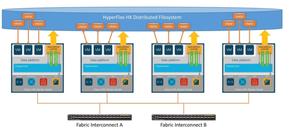
The Cisco HyperFlex system is a fully-contained modular virtual server platform with flexible pools of compute and memory resources, integrated networking, and a distributed log-based filesystem for virtual machine storage. HyperFlex uses a high-performance and highly-available HyperFlex Data Platform (HXDP) software to deliver a hyperconverged platform with distributed storage and Enterprise-grade data management services. The data platform runs on all servers to implement a scale-out, distributed storage file system using internal flash-based SSDs, NVMe storage, or a combination of flash-based SSDs and high-capacity HDDs to store data. HXDP runs on multiple Cisco HyperFlex HX-Series nodes to create a highly available cluster. The data management features provided by HyperFlex include replication, always-on inline deduplication, always-on inline compression, thin provisioning, instantaneous space-efficient clones, and snapshots. Each node also runs a hypervisor software for virtualizing the servers and connects to Fabric Interconnects in a UCS domain. HyperFlex leverages Cisco UCS technology and architecture to deliver an integrated platform with computing, storage, and server networking. HyperFlex also uses software-defined computing, software-defined networking, and software-defined storage to deliver a fully automated, pre-installed, and pre-provisioned virtualized infrastructure ready for hosting application workloads. A HyperFlex system can be deployed as a standard or stretch cluster in an Enterprise data center or as an Edge cluster in smaller or remote site deployments. Figure 33 illustrates the high-level architecture for a HyperFlex system.
Figure 33. HyperFlex System Architecture
In this solution, a single HyperFlex stretched cluster provides the hyperconverged infrastructure. The cluster serves as an Application cluster that spans both data centers, enabling application virtual machines to be deployed in either data center with seamless connectivity and mobility as needed. The HyperFlex servers and UCS Fabric Interconnects in the two data centers are centrally managed from the cloud using Cisco Intersight. Figure 34 illustrates the HyperFlex and UCS design in the two active-active sites.
Figure 34. HyperFlex and Cisco UCS Design
The HyperFlex stretch cluster is a 4+4 cluster, with nodes in the cluster evenly distributed between the sites (Site-A, Site-B) to provide the hyperconverged infrastructure in the active-active data centers. The solution is a 40GbE design within a data center site and 10GbE outside the data center, including inter-site connectivity between data centers provided by the VXLAN Multi-Site fabric. In each site, 4 x HX-series server nodes connect to a pair of Cisco UCS Fabric Interconnects using 2 x 40GbE links. The Cisco UCS Fabric Interconnects then connects to a VXLAN fabric in the site for connectivity between sites and to outside networks and services. The connectivity between stretch cluster nodes within a site, under normal conditions, is through the local Cisco UCS Fabric Interconnects but in certain failure scenarios, the traffic may require the local VXLAN fabric to provide connectivity. The inter-site stretch cluster communication between nodes will always use the VXLAN Multi-Site fabric for Layer 2 and Layer 3 connectivity.
A HyperFlex installer in a third site, outside the fabric, automates the deployment of the stretched cluster across data centers. The VXLAN EVPN Multi-Site fabric provides the necessary reachability to enable the automated deployment. The fabric in each site provides an external connection for accessing networks and services outside the fabric. The external connectivity is through a pair of Border Leaf switches that connect to pair of external Nexus 7000 series gateway switches in the external/outside network. In this design, the HyperFlex Installer uses the external connection in each site to communicate with the HyperFlex and UCS infrastructure in the two active-active sites.
Cisco HyperFlex Stretched Cluster
A HyperFlex “stretched” cluster is designed to provide business continuity in the event of a significant disaster such as site-wide failure that takes down the data center at that location. It is also used when a highly resilient architecture is needed to protect mission critical applications and workloads. Stretch cluster provides geographical redundancy, even if it is between two buildings in a campus environment. Stretch clusters are designed to ensure the availability of the hyperconverged infrastructure, and the VMware vSphere cluster that runs on it. HyperFlex stretch cluster and VMware vSphere cluster that runs on it, are not multiple clusters, but a single cluster that spans data center locations. The HyperFlex servers and ESXi hosts that make up the cluster are geographically distributed across different data center locations. A single VMware vCenter manages the vSphere cluster. Storage Data is mirrored both locally and across data centers.
Stretch Clusters also require a Witness node, one per cluster. The HyperFlex Witness is a VM located in a third location that decides which site becomes the primary when a split-brain failure occurs. Split-brain failure is when the sites cannot communicate with each other, but they can still communicate with the Witness. Stretch clusters require a 100Mbps minimum connection to the Witness, with less than 200ms of RTT latency. Latency to the witness impacts site failure times, so larger clusters with significant load and data, should use RTT times in the order of 10ms or lower. The reachability to the Witness in a third site can be Layer 2 or Layer 3. Layer 3 is used in this solution.
To meet write latency requirements of applications such as databases, the sites in a stretch cluster require 10Gbps of bandwidth per cluster and a less than 5ms round-trip time (RTT) network latency.
A “stretched” HyperFlex cluster requires a symmetric configuration between sites (including Fabric Interconnects), with a minimum of two HX-series “converged” nodes (i.e. nodes with shared disk storage) in each site. Each site can support up to a maximum of 16 SFF or 8SFF converged nodes per site (at the time of writing this document), but both sites must have the same number of nodes to maintain the symmetric configuration. In a stretch cluster, the converged nodes must be an M5 model or higher. Stretch cluster can also be expanded to include compute-only nodes for additional processing capacity, but it cannot exceed the total supported node count. At the time of the writing of this document, a HyperFlex stretch cluster can support a maximum cluster size of 64 (16 per site x 2 or 32 converged nodes, plus 32 compute-only) with SFF converged nodes and 48 (8 per site x 2 or 16 converged nodes, plus 32 compute-only) with LFF converged nodes.
Data is replicated across multiple nodes, depending on the replication factor, for continuous
operation in the event of a single-node failure. The default replication factor in a HyperFlex stretch cluster is (2+2), which means that two copies are maintained in each site, for a total of 4 copies. This is to address the different permutations of failure scenarios in a stretch cluster environment.
HyperFlex stretch clusters also require VMware vSphere Enterprise Plus license since it relies on advanced DRS capabilities available only in the premium edition.
![]() Stretch clusters currently do not support self-encrypting drives (SED) and require M5 or higher server models. VMware ESXi is the only hypervisor supported HyperFlex stretch clusters.
Stretch clusters currently do not support self-encrypting drives (SED) and require M5 or higher server models. VMware ESXi is the only hypervisor supported HyperFlex stretch clusters.
Cisco HyperFlex Data Platform (HXDP)
The foundation for Cisco HyperFlex systems is the Cisco HyperFlex Data Platform software that runs on each node in a HyperFlex cluster. HyperFlex Data Platform is a purpose-built, high-performance, log-structured, scale-out file system that is designed for hyperconverged environments. The data platform runs on Cisco HX-series nodes to create a highly available cluster. Each node includes an HX Data Platform controller that implements the scale-out and distributed file system using internal flash-based SSDs, NVMe storage, or a combination of flash-based SSDs and high-capacity HDDs to store data. The controllers communicate with each other over 10 or 40 GbE to present a single pool of storage that spans the nodes in the cluster. As nodes are added, the cluster scales linearly to deliver computing, storage capacity, and I/O performance.
In this solution, the HyperFlex servers communicate with each other using 40GbE links (bundled in some cases) within a site and 10GbE links between sites. Each server in the cluster has 6 x 1.2TB HDDs that is used to build the distributed file system. The server configuration can be changed to meet the needs of the Enterprise. HyperFlex supports multiple server models, with different drive configurations.
For more details on HyperFlex Data Platform software architecture and design, see: https://www.cisco.com/c/en/us/products/collateral/hyperconverged-infrastructure/hyperflex-hx-series/white-paper-c11-736814.html
Cisco HyperFlex Server
The Cisco HyperFlex portfolio includes a wide range of Hybrid, All-flash and All-NVMe server models that can also be used in this solution. The HyperFlex servers come in different form factors, and offer great flexibility with respect to capacity, processing and memory options that it offers.
The 4+4 stretch cluster in the solution, is built using HX220C-M5SX model of HyperFlex hybrid servers. The server is a 1RU, small footprint model with a minimum of six, and up to eight 2.4TB, 1.8TB or 1.2TB SAS hard disk drives (HDD) for capacity storage, a 240 GB SSD housekeeping drive, a 480 GB or 800 GB SSD caching drive, and a 240 GB M.2 form factor SSD that acts as the boot drive. For configurations requiring self-encrypting drives, the caching SSD is replaced with an 800 GB SAS SED SSD, and the capacity disks are replaced with 1.2TB SAS SED HDDs.
Figure 35. Cisco HX220C-M5SX Server

Either a 480 GB SATA or 800 GB SAS caching SSD may be chosen. This option is provided to allow flexibility in ordering based on product availability, pricing and lead times. While the SAS option may provide a slightly higher level of performance, the partitioning of the two disk options is the same, therefore the amount of cache available on the system is the same regardless of the model chosen.
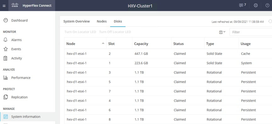
In a HyperFlex cluster, each node with disk storage is equipped with at least one high-performance SSD drive for data caching and rapid acknowledgment of write requests. Each node also is equipped with additional disks, up to the platform’s physical limit, for long term storage and capacity. Caching drives are not factored into the overall cluster capacity, only the capacity disks contribute to total cluster capacity. Many models of servers, drives and form-factors are supported in the solution. However, for validation, the HyperFlex nodes in the cluster used the following drive configuration, with 2 SSDs, one (240GB) for housekeeping, one (480GB) for cache and 6 x 1.2TB capacity drives.
Figure 36. Drive Configuration on HyperFlex Servers used in Validation
For a complete list of HyperFlex server models and specifications supported in this solution, see: https://www.cisco.com/c/en/us/products/hyperconverged-infrastructure/hyperflex-hx-series/index.html#~models
![]() A HyperFlex stretch cluster requires a symmetric configuration across all nodes in the cluster, with M5 or higher server model. For other stretch cluster specific requirements, see HyperFlex Stretch Cluster Guide.
A HyperFlex stretch cluster requires a symmetric configuration across all nodes in the cluster, with M5 or higher server model. For other stretch cluster specific requirements, see HyperFlex Stretch Cluster Guide.
Cisco UCS VIC Interface Card
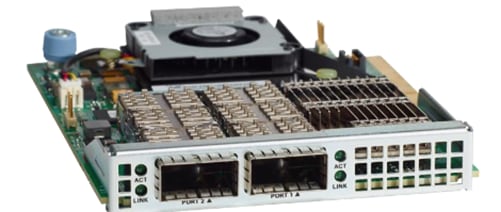
Each HyperFlex server in the solution is equipped with a Cisco UCS VIC 1387 MLOM adapter to enable dual 40GbE connectivity to the 2 x Fabric Interconnects in the site. The VIC 1387 is used in conjunction with the Cisco UCS 6332 or 6332-16UP model Fabric Interconnects to support 40GbE connectivity. The Cisco UCS VIC 1387 MLOM is a dual-port Enhanced Quad Small Form-Factor Pluggable (QSFP+) 40-GbE and Fibre Channel over Ethernet (FCoE)-capable PCI Express (PCIe) modular LAN-on-motherboard (mLOM) adapter that can be installed on any model of Cisco UCS HX-Series Rack Servers.
The mLOM is used to install a Cisco VIC without consuming a PCIe slot, which provides greater I/O expandability. It incorporates next-generation converged network adapter (CNA) technology from Cisco, providing investment protection for future feature releases. The card enables a policy-based, stateless, agile server infrastructure that can present up to 256 PCIe standards-compliant interfaces to the host, each dynamically configured as either a network interface card (NICs) or host bus adapter (HBA). The personality of the interfaces is set programmatically using the service profile associated with the server. The number, type (NIC or HBA), identity (MAC address and World Wide Name [WWN]), failover policy, adapter settings, bandwidth, and quality-of-service (QoS) policies of the PCIe interfaces are all specified using the service profile.
Figure 37. Cisco VIC 1387 mLOM Card
![]() Hardware revision V03 or later of the Cisco VIC 1387 card is required for the Cisco HyperFlex HX-series servers.
Hardware revision V03 or later of the Cisco VIC 1387 card is required for the Cisco HyperFlex HX-series servers.
The HyperFlex stretch cluster nodes connect to separate UCS domains, one in each site. A UCS domain consists of a pair of Cisco UCS 6x00 series Fabric Interconnects and the servers that connect to it. A single Cisco UCS domain can support multiple HyperFlex clusters, the exact number depends on the size of the cluster and the port-density on the Fabric Interconnect model chosen. Cisco UCS Manager that manages the Cisco HyperFlex and UCS servers in the UCS domain, runs on the Fabric Interconnects. In this design, the UCS domains and the associated HyperFlex clusters are also managed centrally from the cloud using Cisco Intersight. Cisco Intersight is a cloud operations, orchestration and management platform for Enterprise data centers and hybrid cloud deployments.
Unified Fabric – Cisco UCS Fabric Interconnects
Cisco UCS Fabric Interconnects (FI) are an integral part of the HyperFlex system. The fabric interconnects providing a unified fabric for integrated LAN, SAN and management connectivity for all HyperFlex servers that connect to the Fabric Interconnects. Fabric Interconnects provide a lossless and deterministic switching fabric, capable of handling I/O traffic from hundreds of servers.
Cisco UCS Fabric Interconnects are typically deployed in pairs to form a single management cluster but with two separate network fabrics, referred to as Fabric A or FI-A and Fabric B or FI-B. Cisco UCS Manager that manages the UCS domain, runs on the Fabric Interconnects. In a UCS domain, one FI is the primary, and the other is the secondary. Each FI has its own IP address and a third roaming IP that serves as the cluster IP address for management. This primary/secondary relationship is only for the management cluster and has no effect on data transmission. The network fabric on both Fabric Interconnects are active at all times, forwarding data on both network fabrics while providing redundancy in the event of a failure. A HyperFlex cluster connects to the VXLAN fabric through a UCS domain, with every node in the cluster connecting to both Fabric Interconnects in the Cisco UCS domain.
The Fabric Interconnect model used in a UCS domain will determine the link speeds that can be used for connecting upstream to the VXLAN fabric and downstream to the servers. Two Fabric Interconnect models are used in this design though other models and uplinks are also supported:
● Cisco UCS 6400 series fabric interconnects provide a 10/25GbE unified fabric with 10/25GbE uplinks for northbound connectivity to the VXLAN fabric and 10/25GbE downlinks for southbound connectivity to HyperFlex servers.
● Cisco UCS 6300 series fabric interconnects provide a 40GbE unified fabric with 40GbE uplinks for northbound connectivity to the VXLAN fabric and 40GbE downlinks for southbound connectivity to HyperFlex servers.
The specific Cisco UCS 6300 and 6400 series models that can be used in HyperFlex deployments are described below:
Cisco UCS 6332 Fabric Interconnect
The Cisco UCS 6332 Fabric Interconnect is a one-rack-unit (1RU) 40 Gigabit Ethernet and FCoE switch offering up to 2560 Gbps of throughput. The switch has 32 40-Gbps fixed Ethernet and FCoE ports. Up to 24 of the ports can be reconfigured as 4x10Gbps breakout ports, providing up to 96 10-Gbps ports, although Cisco HyperFlex nodes must use a 40GbE VIC adapter in order to connect to a Cisco UCS 6300 Series Fabric Interconnect.
Figure 38. Cisco UCS 6332 Fabric Interconnect
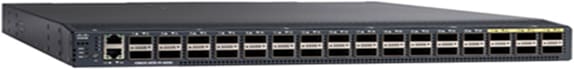
Cisco UCS 6332-16UP Fabric Interconnect
The Cisco UCS 6332-16UP Fabric Interconnect is a one-rack-unit (1RU) 10/40 Gigabit Ethernet, FCoE, and native Fibre Channel switch offering up to 2430 Gbps of throughput. The switch has 24 40-Gbps fixed Ethernet and FCoE ports, plus 16 1/10-Gbps fixed Ethernet, FCoE, or 4/8/16 Gbps FC ports. Up to 18 of the 40-Gbps ports can be reconfigured as 4x10Gbps breakout ports, providing up to 88 total 10-Gbps ports, although Cisco HyperFlex nodes must use a 40GbE VIC adapter in order to connect to a Cisco UCS 6300 Series Fabric Interconnect.
Figure 39. Cisco UCS 6332-16UP Fabric Interconnect
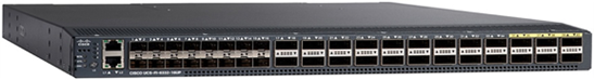
When used for a Cisco HyperFlex deployment, due to mandatory QoS settings in the configuration,
the 6332 and 6332-16UP will be limited to a maximum of four 4x10Gbps breakout ports, which can be used for other non-HyperFlex servers.
Cisco UCS 6454 Fabric Interconnect
The Cisco UCS 6454 54-Port Fabric Interconnect is a One-Rack-Unit (1RU) 10/25/40/100 Gigabit Ethernet, FCoE and Fibre Channel switch offering up to 3.82 Tbps throughput and up to 54 ports. The switch has 28 10/25-Gbps Ethernet ports, 4 1/10/25-Gbps Ethernet ports, 6 40/100-Gbps Ethernet uplink ports and 16 unified ports that can support 10/25-Gbps Ethernet ports or 8/16/32-Gbps Fibre Channel ports. All Ethernet ports are capable of supporting FCoE. Cisco HyperFlex nodes can connect at 10-Gbps or 25-Gbps speeds depending on the model of Cisco VIC card in the nodes and the SFP optics or cables chosen.
Figure 40. Cisco UCS 6454 Fabric Interconnect
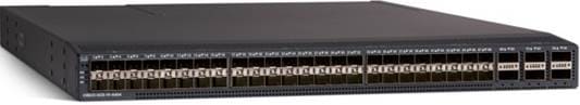
The HyperFlex nodes connect to pair of Cisco UCS 6300 series Fabric Interconnects in this solution. The Fabric Interconnect can connect to the upstream VXLAN fabric using multiple 10/25/40-GbE links in a virtual Port-channel (vPC) configuration for more resiliency and higher aggregate uplink bandwidth.
Uplink Connectivity to Data Center Network Fabric
The Cisco UCS Fabric Interconnects in this design connect to Cisco Nexus 9000 series leaf switches in the Cisco VXLAN fabric and provide uplink or northbound connectivity to other parts of the Enterprise. The Application cluster uses a HyperFlex stretched cluster with 2 pairs of Cisco UCS Fabric Interconnects, one in each site, to provide connectivity to the HyperFlex nodes in that site.
For redundancy and higher uplink bandwidth, multiple links from each FI are used for uplink connectivity to data center fabric. Cisco UCS FI supports 802.3ad standards for aggregating links into a port-channel (PC) using Link Aggregation Protocol (LACP). Multiple links on each FI are bundled together in a port-channel and connected to upstream switches in the data center network. The port-channel provides link-level redundancy and higher aggregate bandwidth for LAN, SAN and Management traffic to/from the UCS domain. The switches in the data center fabric that connect to single FI are bundled into a virtual Port Channel (vPC). vPC enables links that are physically connected to two different switches to be bundled such that it appears as a “single logical" port channel to a third device (in this case, FI). This PC/vPC based design has many benefits such as:
● Higher resiliency - both link and node-level redundancy
● Higher uplink bandwidth by bundling links
● Flexibility to increase the uplink bandwidth as needed by adding more links to the bundle.
All uplinks on the Cisco UCS FIs operate as trunks, carrying multiple 802.1Q VLAN IDs across the uplinks. And all VLAN IDs defined on Cisco UCS should be trunked across all available uplinks. This is important as traffic may need to be forwarded between servers in the UCS domain but use different fabric (FI-A, FI-B) as its primary data path. There are also failure scenarios where a VIC or an internal fabric level port or link failure results in traffic that normally does not leave the Cisco UCS domain, to now be forced over the Cisco UCS uplinks for intra-domain connectivity. Reachability through the second fabric may also be needed for maintenance events such as FI firmware upgrade that may require a fabric to be rebooted.
Downstream Connectivity to HyperFlex Cluster
The Application cluster consists of 4+4 node HyperFlex stretch cluster that connects to a pair of Cisco UCS 6332 Fabric Interconnects in each site. The Fabric Interconnects then connect to the upstream data center network, VXLAN fabric in each site. The Cisco UCS 6300 Fabric Interconnects in each site connect to a pair of upstream Cisco Nexus 9000 series leaf switches in the upstream fabric as follows:
● 2 x 40GbE links from FI-A to Cisco Nexus leaf switches, one to each Leaf switch
● 2 x 40GbE links from FI-B to Cisco Nexus leaf switches, one to each Leaf switch
The FI side ports are configured to be a port-channel, with vPC configuration on the Cisco Nexus leaf switches. The two links from separate Cisco Nexus 9000 leaf switches in the VXLAN fabric that connect to a specific FI is configured to be part of the same vPC.
The connectivity described above, provides the UCS domain with redundant paths and 160Gbps (40Gbps per link x 2 uplinks per FI x 2 FI) of aggregate uplink bandwidth to/from the VXLAN fabric. The uplink bandwidth can be increased as needed by adding additional connections to the port-channel.
The VLANs for in-band management, vMotion, storage data and VM network VLANs are then enabled on the uplinks of Fabric Interconnects in both data centers. The VLANs are also enabled on the individual vNIC templates going to each server in the HyperFlex cluster.
Each server in the cluster uses a VIC 1387 adapter with two 40Gbps uplink ports to connect to each FI, forming a path through each fabric (FI-A, FI-B). The two uplink ports are bundled in a port-channel to provide 2x40Gbps of uplink bandwidth from each server and redundancy in the event of a failure.
Figures 41 and 42 show the stretched cluster connectivity from HyperFlex stretch cluster nodes to Cisco UCS Fabric Interconnects to Cisco Nexus 9000 series Leaf switches in the fabric in Site-A and Site-B respectively.
Figure 41. Cisco UCS and HyperFlex Connectivity in Site-A
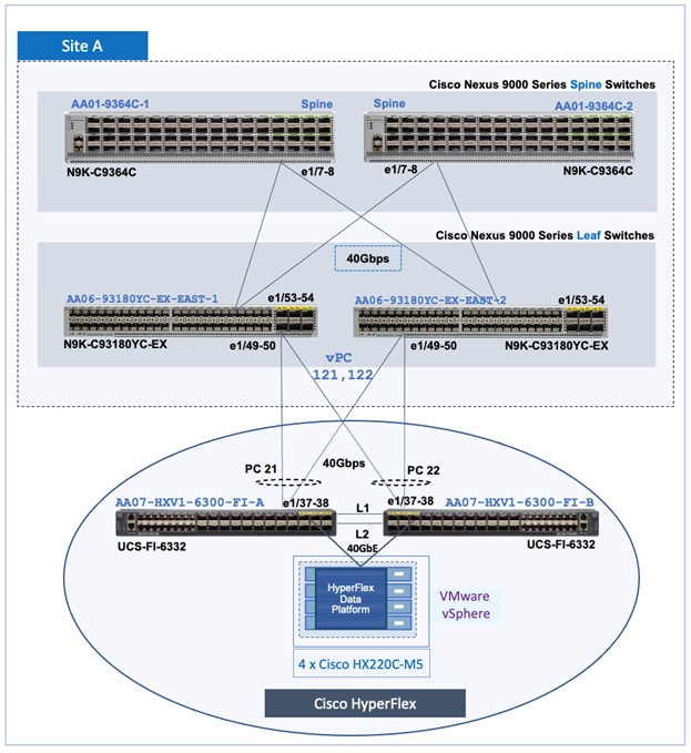
Figure 42. Cisco UCS and HyperFlex Connectivity in Site-B
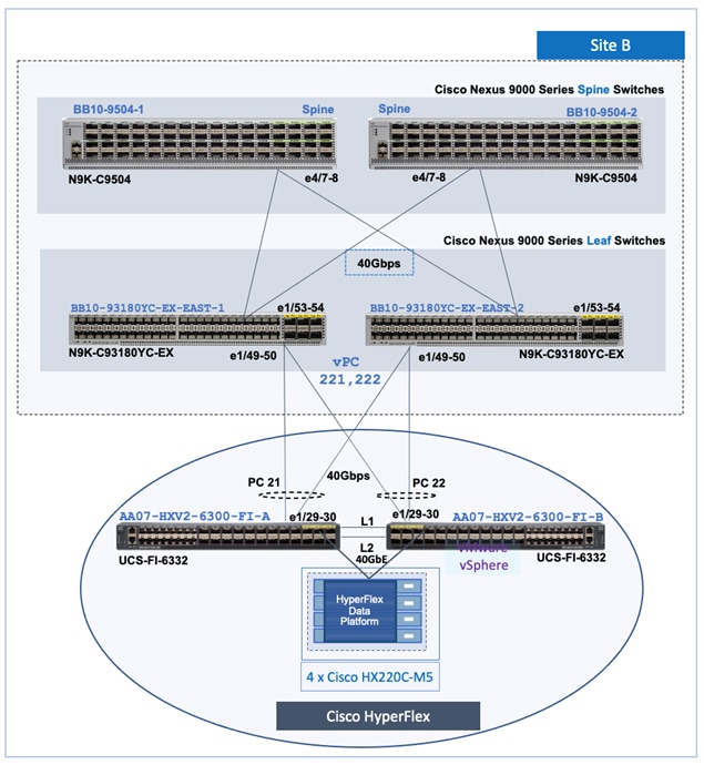
Other Considerations
● Jumbo Frames
HyperFlex uses jumbo frames for storage and vMotion. Jumbo frames should therefore be enabled end-to-end, within the Cisco UCS domain and across the VXLAN Multi-Site fabric to prevent service interruptions or during planned maintenances such as Cisco UCS firmware upgrades, or when a cable or port failure would cause storage traffic to traverse northbound to the VXLAN fabric.
● Connectivity for HyperFlex Installation
To deploy a HyperFlex system, the HyperFlex installer VM requires connectivity to the UCS domain as follows:
◦ IP connectivity to the management interfaces of both Fabric Interconnects – this is typically an out-of-band network dedicated for management.
◦ IP connectivity to the external management IP address of each server in the HX cluster. This IP address comes from an IP Pool (ext-mgmt) defined as a part of the service profile template for configuring the servers in the cluster. The IP address is assigned to the CIMC interface on each server which is reachable through the out-of-band management network of the Fabric Interconnects.
The out-of-band network that provides the above connectivity is not part of the VXLAN fabric. However, connectivity between the VXLAN fabric and the out-of-band network is through the external connectivity provided by each site fabric.
Cisco HyperFlex Networking Design
The Cisco HyperFlex system requires multiple VLANs and IP subnets to enable connectivity between the different sub-components within the HyperFlex system. In a HyperFlex stretched cluster, these VLANs and IP subnets need to also extend across sites for the cluster to operate as intended since the nodes are part of a single cluster. HyperFlex installer will deploy identical VLANs and UCS networking in the two active-active data centers.
The networking design in a HyperFlex system consists of the following networks:
Out-of-Band Management: This network enables out-of-band access to the Cisco UCS Fabric Interconnects in the UCS domain and to the HyperFlex servers that connect to the domain. The interfaces in this network are the management IP addresses for the individual FIs (and FI cluster IP), external management interfaces on the HyperFlex servers (reachable via FI management).
In-Band Management: This network is for management communication between all nodes in a HyperFlex cluster. This includes ESXi hosts and storage controller virtual machines (SCVM) running on each HyperFlex node in the cluster. The specific management interfaces in a HyperFlex cluster are as follows:
● SCVM Management Interface (one per server)
● ESXi Management Interface (one per host)
● Roaming HyperFlex Management Cluster IP (one per cluster)
● SCVM Replication Interface (one per server, if enabled)
● Roaming HyperFlex Replication Cluster IP (one per cluster)
Storage Data: This network is for all storage related communication, used by the HyperFlex Data Platform (HXDP) software, ESXi hosts and SCVMs to enable the Distributed Data Filesystem that HyperFlex uses to provide storage services. This network is also used to service storage IO requests from Guest VMs running on the HyperFlex cluster. The communication on this network is critical for the proper operation of the storage cluster, integrity of the storage data and access to the storage services. This network must support Jumbo frames. The specific storage data interfaces in a HyperFlex cluster are:
● SCVM Storage Data Interface (one per server)
● Roaming HyperFlex Storage Cluster IP (one per HX cluster)
● ESXi Storage Data VMkernel Interface (one per host)
● VMkernel interface for storage access on each ESXi host in the HX cluster
vMotion: This network is used by ESXi hosts to vMotion guest VMs from host to host in the vSphere cluster running on the HyperFlex cluster. To minimize recovery time, vMotion network should use Jumbo frames for quick migration of VMs after a failure. The specific interface in this network is the vMotion VMkernel interface on each ESXi host in the cluster.
Virtual Machine: The networks used by Guest VMs running on the HyperFlex cluster is included here for the sake of completeness. VM networks provide connectivity to the guest virtual machines deployed on the vSphere cluster running on the HyperFlex stretch cluster. There could be several VM networks on a given host in the cluster.
Figure 43 illustrates the HyperFlex networking for In-Band Management, Storage and vMotion at HyperFlex node and cluster level.
Figure 43. HyperFlex Networking - Node and Cluster Level
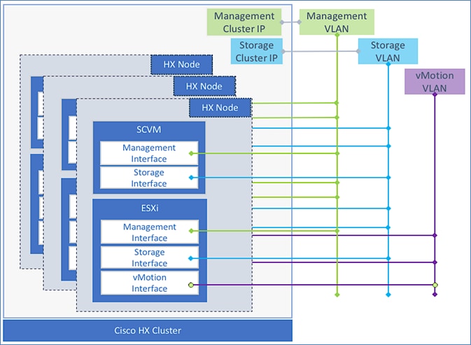
Best Practices and other Guidelines
The design guidelines and best practices for HyperFlex networking and their use in this design are as follows.
● The HyperFlex storage data must be on a dedicated network and therefore must be in a separate VLAN, should not be used for other traffic.
● The HyperFlex installer, during installation, requires reachability to the components in the UCS domain, specifically the Fabric Interconnect’s cluster management IP address and the external management (ext-mgmt) IP addresses of the UCS servers (HX nodes). Cluster management IP is a roaming IP that is assigned to the primary Fabric Interconnect and both the cluster IP and the external management IP of the HX nodes are reachable via the dedicated management ports on each FI.
● All storage and vMotion traffic in a HyperFlex system is configured to use jumbo frames by default. Jumbo frames enable IP traffic to use a Maximum Transmission Unit (MTU) size of 9000 bytes. Larger MTU value enables each IP packet to carry a larger payload, therefore transmitting more data per packet, and consequently sending and receiving data faster. The HyperFlex installer will configure the uplinks (vNICs) on all servers in the HX cluster to use a jumbo frame MTU for storage and vMotion. Links end-to-end must also be configured for jumbo frames.
● Replication Networking is setup after the initial install. Replication was not validated in this design. For a detailed discussion on HyperFlex Replication – see Cisco HyperFlex 4.0 for Virtual Server Infrastructure with VMware ESXi design guide listed in the References section.
Validation
Table 3 lists the HyperFlex networks and VLANs used for validating the design in Cisco Labs. The HyperFlex Installer will provision the networks in both UCS domains and on ESXi hosts in the vSphere cluster. For each network type listed, HyperFlex will create a corresponding VMware virtual switch (vSwitch) on each ESXi host in the HyperFlex cluster. The installer will also provision the virtual switches with port-groups for each of the VLANs listed. The VLANs are also configured on the uplinks from the Cisco UCS Fabric Interconnects to the VXLAN fabric and on the HyperFlex servers vNICs.
If replication is enabled (to a second cluster), an additional VLAN will also be required. The replication VLAN will map to a port-group on the inband management vSwitch. Replication networking is not part of the initial automated install of the HyperFlex cluster. Replication was not validated in this design.
All HyperFlex infrastructure VLANs need to be extended (Layer 2 or Layer 3) across the VXLAN EVPN Multi-Site fabric to enable intra-cluster communication within the HyperFlex cluster.
Table 3. HyperFlex Networks and VLANs
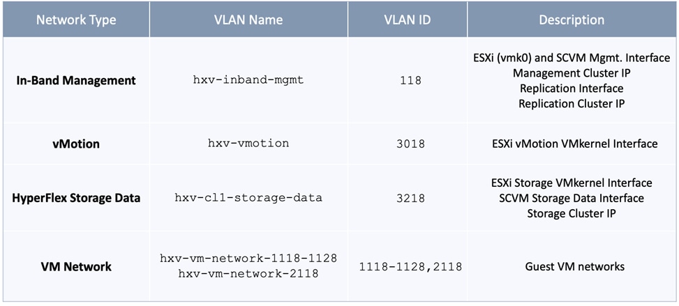
The HyperFlex Installer uses the VM Network VLAN pool to create VLANs in the Cisco UCS domain (FI) and port-groups in vSphere. Additional VLANs can be added for VM network as needed. The VM network VLANs are initially mapped to port-groups on a VMware virtual switch which can be migrated to a VMware virtual distributed switch (vDS) as needed. All HyperFlex VM networks may also need to be extended (Layer 2 or Layer 3) across the VXLAN EVPN Multi-Site fabric depending on the needs of the application or service.
Virtualization Layer Design
In the HyperFlex Stretch cluster solution with VXLAN EVPN Multi-Site fabric, a single VMware vCenter manages the virtualized server infrastructure in the two active-active data centers. The virtualized server infrastructure is a single vSphere cluster that spans both data centers. VMware vSphere is deployed on the HyperFlex stretch cluster nodes to create the vSphere cluster. The VMware vCenter server VM is deployed in a third site with reachability to hosts in both sites that make up the vSphere cluster.
Enterprises can deploy virtual machines in either location because of the workload placement flexibility and mobility enabled by the active-active data center design. For application and services virtual machines deployed on the ESXi cluster, datastores are created with site-affinity to host virtual machines locally. Under normal conditions, virtual machines in a given site will access storage from same site. As part of implementation design, the distribution of the virtual machines across the two sites must be determined, and some virtual machines are hosted primarily in site A while the others are hosted in site B. You can determine this virtual machine and application distribution across the two sites according to your site preferences and requirements. For optimal performance, the virtual-machine disks for the VMs should be hosted on the local datastore to avoid additional latency and traffic across sites. VMware DRS should be configured with site affinity rules to make sure the virtual machines adhere to site preference requirements.
Virtual Networking for Cisco HyperFlex
The HyperFlex installer deploys the Cisco HyperFlex system with a pre-defined virtual networking design on the ESXi hosts in the cluster. The virtual networking for a HyperFlex stretched cluster is identical across all hosts in the cluster regardless of their location. The design segregates the different types of traffic through the HyperFlex system using different VMware virtual switches (vSwitch). Four virtual switches are created by the HyperFlex installer as summarized below. Each vSwitch is assigned two uplinks – the uplink adapters seen by the host at the hypervisor level are virtual NICs (vNICs) created on the VIC converged network adapter installed on the HX server. The vNICs for each server are created in Cisco UCS Manager using service profiles. Installer creates the vNICs as well.
The virtual Switches created by the installer are:
vswitch-hx-inband-mgmt: This is the default ESXi vSwitch0 which is renamed by the ESXi kickstart file as part of the automated installation. The switch has two uplinks, active on fabric A and standby on fabric B – jumbo frames are not enabled on these uplinks. The following port groups are created on this switch:
● Port group for the standard ESXi Management Network. The default ESXi VMkernel port: vmk0, is configured as a part of this group on each ESXi HX node.
● Port Group for the HyperFlex Storage Platform Controller Management Network. The SCVM management interfaces is configured as a part of this group on each HX node.
● If replication is enabled across two HX clusters, a third port group should be deployed for VM snapshot replication traffic.
vswitch-hx-storage-data: This vSwitch is created as part of the automated installation. The switch has two uplinks, active on fabric B and standby on fabric A – jumbo frames are enabled on these uplinks (recommended):
● Port group for the ESXi Storage Data Network. The ESXi VMkernel port:vmk1 is configured as a part of this group on each HyperFlex node.
● Port group for the Storage Platform Controller VMs. The SCVM storage interfaces is configured as a part of this group on each HyperFlex node.
vmotion: This vSwitch is created as part of the automated installation. The switch has two uplinks, active on fabric A and standby on fabric B – jumbo frames are enabled on these uplinks (recommended). The IP addresses of the VMkernel ports (vmk2) are configured by using post_install script.
vswitch-hx-vm-network: This vSwitch is created as part of the automated installation. The switch has two uplinks, active on both fabrics A and B – jumbo frames are not enabled on these uplinks.
The Cisco UCS vNIC template for In-Band Management, Storage Data, vMotion and VM network are all configured for VLAN tagging. The corresponding port-groups in ESXi are also explicitly configured for the VLAN associated with that port-group.
Virtual Networking Design using VMware vSphere vSwitch
Figure 44 shows the default virtual networking deployed by the HyperFlex Installer on ESXi hosts.
Figure 44. Virtual Networking Design on HyperFlex ESXi Host
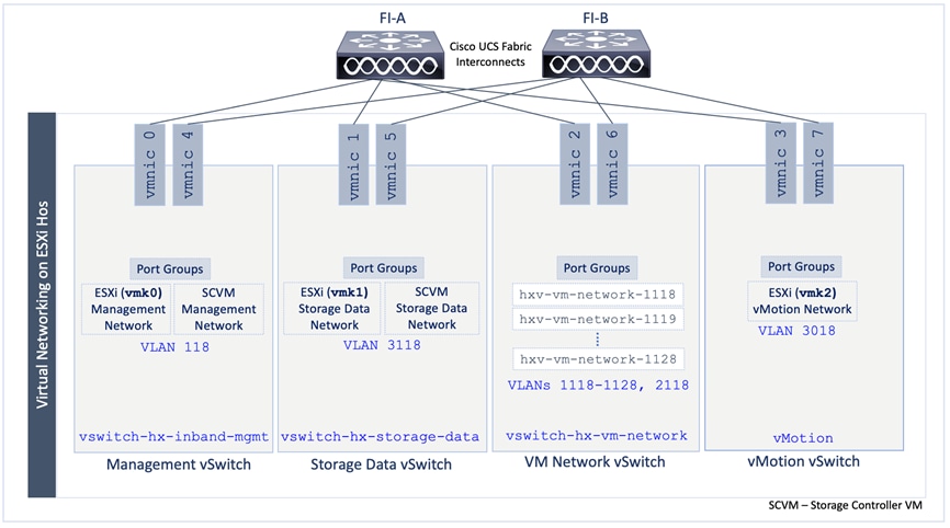
For applications guest VMs, the virtual networking design can be changed from using the default VMware vSwitch to VMware vDS. The infrastructure networks for the HyperFlex system will remain on the VMware vSwitch(s). To support the multi-vSwitch environment, the HyperFlex Installer will use Cisco UCS Manager service profiles to create multiple virtual NIC (vNIC) interfaces on each host. The vNICs are then used as uplinks for the virtual switches, two per host per vSphere vSwitch as shown in the figure above. The HyperFlex installer then deploys the VLANs for management, storage, vMotion, and application traffic on the appropriate vNIC interfaces.
Table 4 lists the networking configuration deployed by the HyperFlex Installer in each Cisco UCS domain.
Table 4. ESXi Host Networking Configuration
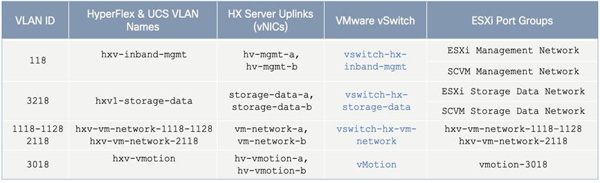
Once the cluster is operational, virtual machine networks may need to be added as new applications and services are added. This requires the VLANs to be provisioned in the Cisco UCS domain and on the ESXi hosts in the cluster. The corresponding networks in the VXLAN fabric must also be provisioned to enable forwarding for those networks (VLANs).
vSphere High Availability Recommendations
VMware vSphere setup is critical for the operation of a HyperFlex stretched cluster. HyperFlex installer deploys many vSphere features such as DRS and virtual machine and host site-affinity groups. In addition, customers should enable the following vSphere High Availability settings in VMware vCenter:
1. Enable vSphere HA using the check-box for Turn on vSphere HA
2. Failure Conditions and responses:
● Use the check-box to Enable Host Monitoring
● For Host Failure Response, select Restart VMs
● For Response for Host Isolation, select Power off and Restart VMs
● For Datastore with PDL, select Power off and Restart VMs
● For Datastore with APD, select Power off and Restart VMs (conservative)
● For VM Monitoring: Customers can enable it if they prefer. It is typically disabled.
3. Set Admission Control to Disable
4. For Heartbeat Datastores, select the button for Use datastores only from the specified list and select HyperFlex datastores in each site.
5. Under Advanced Settings, select:
● False for das.usedefaultisolationaddress to manually enter the following IPs otherwise, default values will be chosen.
● IP address in Site A for das.isolationaddress0 (Management Gateway)
● IP address in Site B for das.isolationaddress1 (IP outside the cluster but not FI VIPs, Cluster IP or Cluster Host IP)
HyperFlex Stretched Cluster - Additional Recommendations
For additional guidelines and up-to-date recommendations on HyperFlex stretched clusters, see Operating Cisco HyperFlex Data Platform Stretched Clusters white paper.
This section provides the detailed procedures for deploying a HyperFlex stretched cluster for providing the VSI in the two active-active data center sites in the solution, interconnected by a VXLAN EVPN Multi-Site fabric. The cluster serves as an Application cluster for hosting mission-critical applications that require the availability that this solution provides.
The deployment procedures covered in this section include:
● Setup of Cisco UCS domains for connecting to HyperFlex stretched cluster nodes in each site.
● Automated discovery and addition of a pair of ToR switches in each site as leaf switches in the VXLAN EVPN Multi-Site fabric.
● Automated provisioning of access layer connectivity in each site, from the ToR leaf switches to the Cisco UCS Fabric Interconnects in each site.
● Automated provisioning of HyperFlex Infrastructure networks in the VXLAN EVPN Multi-Site fabric to enable connectivity and forwarding between nodes in each site.
● Deployment of a HyperFlex stretch cluster and VMware vSphere cluster across both sites.
● Deployment of HyperFlex Witness in a third site, outside the VXLAN EVPN Multi-Site fabric.
● Enabling Intersight management of Cisco UCS Fabric Interconnects and HyperFlex cluster.
The following provisioning tools and methods are used for deploying the solution:
● Console and Cisco UCSM GUI for the setup of Cisco UCS domains in each site and to provision uplink connectivity from the Cisco UCS domain to the VXLAN fabric.
● HashiCorp Terraform Provider for Cisco DCNM automates the Day 2 provisioning of the VXLAN Multi-Site fabric to support the HyperFlex VSI cluster that spans two data center sites.
● Cisco HyperFlex Installer VM automates the Day 0 deployment of HyperFlex stretched cluster running VMware vSphere.
● Cisco Intersight Orchestrator deploys the HyperFlex Installer and HyperFlex Witness. The workflow can be exported to external repository for future use or maintained in Intersight for use in a larger automation efforts. The OVA deployment directly from VMware vCenter is provided in this document
● Cisco DCNM Fabric Builder provides GUI-driven automation for the Day 0 deployment of the end-to-end VXLAN Multi-Site fabric.
The Cisco HyperFlex Installer VM used in the solution is located in a third site, outside the VXLAN EVPN Multi-Site fabric. Other infrastructure services such as Active Directory, DNS, VMware vCenter and HyperFlex Witness are also hosted in this third location with reachability to both data center sites.
![]() Cisco Intersight currently does not support the HyperFlex stretch cluster installation.
Cisco Intersight currently does not support the HyperFlex stretch cluster installation.
The high-level steps for deploying a HyperFlex stretch cluster in a Cisco VXLAN Multi-Site fabric are as follows:
● Setup Cisco UCS domains (one per site) for connecting HyperFlex servers in the cluster.
● Setup VXLAN fabric to enable infrastructure connectivity to Cisco UCS Fabric Interconnects, HyperFlex stretch cluster nodes and VMware vSphere hosts. The setup includes establishing access-layer connectivity to the UCS domain in each site and provisioning networks and related forwarding constructs (Sites, VRFs) to enabled forwarding through the fabric. The connectivity must be in place before a stretch cluster can be installed using the nodes in the two active-active sites. The connectivity also establishes connectivity between ESXi nodes in the vSphere cluster that spans the two sites. The connectivity is also necessary for the continued operation of the Cisco HyperFlex stretch cluster and VMware Sphere cluster.
● Install HyperFlex stretched cluster using a HyperFlex Installer VM located in a third site. The VXLAN fabric must provide connectivity from the HyperFlex and UCS infrastructure in the two active-active data center sites to the HyperFlex Installer VM and other key services (HyperFlex Witness, VMware vCenter) located outside the fabric. The fabric must also provide Layer 2 connectivity between HyperFlex nodes in the two sites for intra-cluster communication.
● Complete post-Install tasks (for example, licensing, vMotion setup, provisioning datastores, enabling Intersight management etc.) as well as enabling management for the deployed cluster
Once the setup is complete, the HyperFlex VSI is ready to host application virtual machines in either data center locations.
Setup Cisco UCS Domain for HyperFlex – using Console and Cisco UCSM GUI
A HyperFlex stretch cluster requires two UCS domains, one in each site for connecting to the HyperFlex nodes in that site. This section covers the setup of a new Cisco UCS domain in one site. Use the same procedures for the second site. This section also provides detailed steps for enabling Cisco Intersight management for the Cisco UCS domain.
Table 5 provides the initial setup information for the two UCS domains in the solution.
Table 5. Cisco UCS Domain Setup Information

Table 6 provides the uplink port-channel information for the two UCS domains in the solution.
Table 6. Cisco UCS Domain: Uplink Port-Channel Setup Information
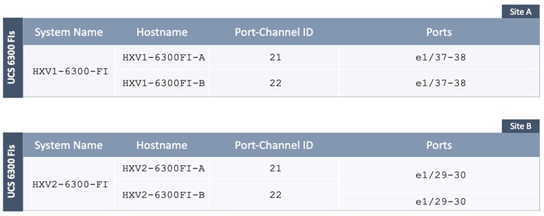
Table 7 provides the connectivity information for the HyperFlex servers in the two UCS domains.
Table 7. Cisco UCS Domain: HyperFlex Server Port Setup Information
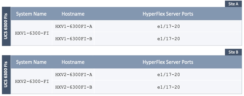
Initial Setup of Cisco UCS Domain in Site-A
Follow the procedures outlined in this section to deploy a new Cisco UCS domain for the HyperFlex nodes in Site-A using the provided setup information.
Setup Cisco UCS Fabric Interconnect A (FI-A)
To deploy the first fabric interconnect (FI-A) in the UCS domain, connect to the FI console and step through the Basic System Configuration Dialogue:
---- Basic System Configuration Dialog ----
This setup utility will guide you through the basic configuration of
the system. Only minimal configuration including IP connectivity to
the Fabric interconnect and its clustering mode is performed through these steps.
Type Ctrl-C at any time to abort configuration and reboot system.
To back track or make modifications to already entered values,
complete input till end of section and answer no when prompted
to apply configuration.
Enter the configuration method. (console/gui) ? console
Enter the setup mode; setup newly or restore from backup. (setup/restore) ? setup
You have chosen to setup a new Fabric interconnect. Continue? (y/n): y
Enforce strong password? (y/n) [y]:
Enter the password for "admin":
Confirm the password for "admin":
Is this Fabric interconnect part of a cluster(select 'no' for standalone)? (yes/no) [n]: yes
Enter the switch fabric (A/B) []: A
Enter the system name: HXV1-6300-FI
Physical Switch Mgmt0 IP address : 192.168.167.205
Physical Switch Mgmt0 IPv4 netmask : 255.255.255.0
IPv4 address of the default gateway : 192.168.167.254
Cluster IPv4 address : 192.168.167.204
Configure the DNS Server IP address? (yes/no) [n]: yes
DNS IP address : 10.99.167.244
Configure the default domain name? (yes/no) [n]: yes
Default domain name : hxv.com
Join centralized management environment (UCS Central)? (yes/no) [n]:
Following configurations will be applied:
Switch Fabric=A
System Name=HXV1-6300-FI
Enforced Strong Password=yes
Physical Switch Mgmt0 IP Address=192.168.167.205
Physical Switch Mgmt0 IP Netmask=255.255.255.0
Default Gateway=192.168.167.254
Ipv6 value=0
DNS Server=10.99.167.244
Domain Name=hxv.com
Cluster Enabled=yes
Cluster IP Address=192.168.167.204
NOTE: Cluster IP will be configured only after both Fabric Interconnects are initialized. UCSM will be functional only after peer FI is configured in clustering mode.
Apply and save the configuration (select 'no' if you want to re-enter)? (yes/no): yes
Applying configuration. Please wait.
Configuration file - Ok
Cisco UCS 6300 Series Fabric Interconnect
HXV1-6300-FI-A login:
Setup Cisco UCS Fabric Interconnect B (FI-B)
Setup the second Fabric Interconnect (FI-B) in the UCS domain by connecting to the FI console:
Enter the configuration method. (console/gui) ? console
Installer has detected the presence of a peer Fabric interconnect. This Fabric interconnect will be added to the cluster. Continue (y/n) ? y
Enter the admin password of the peer Fabric interconnect:
Connecting to peer Fabric interconnect... done
Retrieving config from peer Fabric interconnect... done
Peer Fabric interconnect Mgmt0 IPv4 Address: 192.168.167.205
Peer Fabric interconnect Mgmt0 IPv4 Netmask: 255.255.255.0
Cluster IPv4 address : 192.168.167.204
Peer FI is IPv4 Cluster enabled. Please Provide Local Fabric Interconnect Mgmt0 IPv4 Address
Physical Switch Mgmt0 IP address : 192.168.167.206
Apply and save the configuration (select 'no' if you want to re-enter)? (yes/no): yes
Applying configuration. Please wait.
Wed Jul 11 02:23:14 UTC 2021
Configuration file - Ok
Cisco UCS 6300 Series Fabric Interconnect
HXV1-6300-FI-B login:
Initial Setup of Cisco UCS Domain in Site-B
Follow the procedures outlined in the Initial Setup of Cisco UCS Domain in Site-A section to deploy a new Cisco UCS domain in Site-B using the provided setup information.
Complete Cisco UCS Domain Setup in Site-A
Configure the following settings, policies and ports in Cisco UCS Manager prior to beginning the HyperFlex installation.
To log into the Cisco UCS Manager, follow these steps:
1. Use a browser to navigate to the Cluster IP of the Cisco UCS Fabric Interconnects.
2. Click the Launch UCS Manager to launch Cisco UCS Manager.
3. Click Login to log in to Cisco UCS Manager using the admin account.
4. If prompted to accept security certificates, accept as necessary.
Upgrade Cisco UCS Firmware (if needed)
Verify that the firmware versions running on Cisco UCS Fabric Interconnects is a supported version for the HyperFlex version being deployed. To upgrade the Cisco UCS Manager version, the Fabric Interconnect firmware, and the server bundles used in this document, please refer to the documentation available here.
Configure Cisco UCS Call Home and Anonymous Reporting (Optional)
Cisco highly recommends that you enable Call Home in Cisco UCS Manager. Configuring Call Home will accelerate resolution of support cases.
To configure Call Home, follow these steps:
1. Use a browser to navigate to the Cisco UCS Manager GUI. Log in using the admin account.
2. From the left navigation pane, select the Admin icon.
3. Select All > Communication Management > Call Home.
4. In the General Tab, change the State to On.
5. Use the other tabs to set Call Home Policies and other preferences, including Anonymous Reporting which enables data to be sent to Cisco for implementing enhancements and improvements in future releases and products.
Configure NTP
To synchronize the Cisco UCS environment to NTP, follow these steps:
1. Use a browser to navigate to the Cisco UCS Manager GUI. Log in using the admin account.
2. From the left navigation menu, select the Admin icon.
3. From the left navigation pane, expand and select All > Time Zone Management > Timezone.
4. In the right windowpane, for Time Zone, select the appropriate time zone from the drop-down list.
5. In the NTP Servers section, click [+] Add to add NTP servers.
6. In the Add NTP Server pop-up window, specify the NTP server to use.
7. Click OK and Save Changes to accept.
Modify Chassis Discovery Policy – For Blade Servers Only (Optional)
To add Cisco UCS server blades in a Cisco UCS 5108 blade server chassis as compute-only nodes in an extended HyperFlex cluster design, the chassis discovery policy must be configured. The Chassis Discovery policy defines the number of links between the Fabric Interconnect and the Cisco UCS Fabric Extenders on the blade server chassis. The links determine the uplink bandwidth from the chassis to FI and must be connected and active before the chassis will be discovered. The Link Grouping Preference setting specifies if the links will operate independently, or if Cisco UCS Manager will automatically combine them into port-channels. The number of links and the port types available on the Fabric Extender and Fabric Interconnect models will determine the uplink bandwidth. Cisco best practices recommends using link grouping (port-channeling). For 10 GbE connections Cisco recommends 4 links per side, and for 40 GbE connections Cisco recommends 2 links per side.
To modify the chassis discovery policy when using a blade server chassis with HyperFlex, follow these steps:
1. Use a browser to navigate to the Cisco UCS Manager GUI. Log in using the admin account.
2. From the left navigation menu, select the Equipment icon.
3. From the left navigation pane, select All > Equipment.
4. In the right pane, click the Policies tab.
5. Under the Global Policies tab, set the Chassis/FEX Discovery Policy (for Action) to match the minimum number of uplink ports that are cabled between the fabric extenders on the chassis and the fabric interconnects.
6. Set the Link Grouping Preference to Port Channel.
7. Click Save Changes and OK to complete.
Configure Uplink Ports on Fabric Interconnects in Site-A
The Ethernet ports on Cisco UCS Fabric Interconnects can operate in different modes depending on what is connected to them. The ports can be configured as Network ports, Server ports, Appliance ports, and so on. By default, all ports are unconfigured.
To connect to the upstream network (in this case, the VXLAN EVPN Fabric), the ports connecting to the Leaf switches should be configured as Network ports. Complete the following steps to configure each Cisco UCS FI’s uplink ports as network ports:
1. Use a browser to navigate to the Cisco UCS Manager GUI. Log in using the admin account.
2. From the left navigation menu, select the Equipment icon.
3. From the left navigation pane, expand and select All > Equipment > Fabric Interconnects > Fabric Interconnect A > Fixed Module (or Expansion Module as appropriate) > Ethernet Ports.
4. In the right pane, select the uplink port. Right-click to select Enable and then right-click again to select Configure as Uplink Port.
5. Click Yes and OK to confirm.
6. Repeat steps 1 – 5 for all uplink ports in FI-A that connect to the VXLAN fabric.
7. Navigate to All > Equipment > Fabric Interconnects > Fabric Interconnect B > Fixed Module (or Expansion Module as appropriate) > Ethernet Ports.
8. Select the uplink port. Right-click to select Enable and then right-click again to select Configure as Uplink Port.
9. Click Yes and OK to confirm.
10. Repeat steps 7 – 9 for all uplink ports in FI-B that connect to the VXLAN fabric.
11. Verify that both FI-A and FI-B uplink ports show as Network ports with an Overall Status of Up.
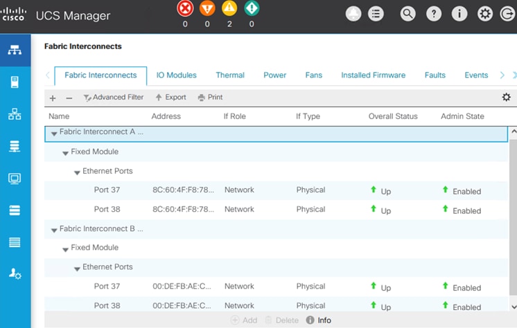
Configure Port-Channeling on Fabric Interconnect Uplink Ports in Site-A
The uplink ports on each FI are bundled into a port-channel. The ports are connected to different Cisco Nexus Leaf switches in the VXLAN EVPN fabric. The leaf switches are part of a virtual Port-Channel (vPC) domain, with two vPCs configured, one to each FI. See the Solution Deployment – HyperFlex Stretch Cluster section of this document for the corresponding vPC configuration from the leaf switches to each Fabric Interconnect in the pair.
To configure a port-channel on the uplink networks ports on each FI, follow these steps:
1. Use a browser to navigate to the Cisco UCS Manager GUI. Log in using the admin account.
2. From the left navigation menu, select the LAN icon.
3. From the left navigation pane, expand and select All > LAN > LAN Cloud > Fabric A.
4. Right-click Fabric A and select Create Port Channel from the list.
5. In the Create Port Channel wizard, in the Set Port Channel Name section, for ID, specify a unique Port-Channel ID for this port-channel and for Name, specify a name for this port-channel. Click Next.
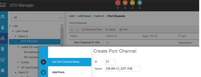
6. In the Add Ports section, select the uplink ports from the Ports table and use the >> to add them to the Ports in the port channel table. Click Finish and OK to complete.
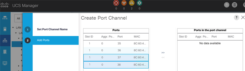
7. Verify the port-channel is up and running on FI-A with Active members (uplink network ports).
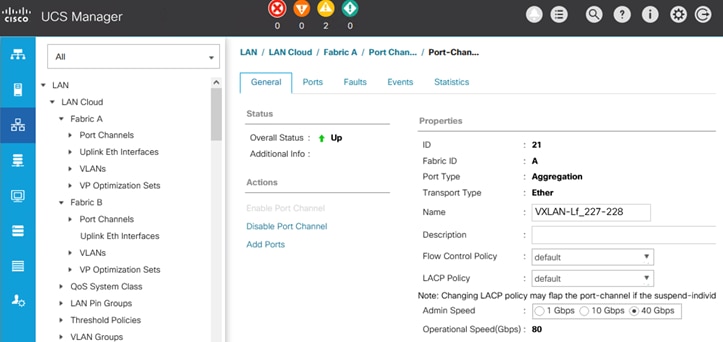
8. Repeat steps 1 - 7 to create a port-channel using the uplink ports on FI-B.
9. Verify the port channel is up and running on FI-B with Active members (uplink network ports).

Configure Downlink Ports to HyperFlex Servers
The Ethernet ports on Cisco UCS Fabric Interconnects that connect to the HyperFlex servers must be defined as server ports. When a server port comes online, a discovery process starts on the connected HyperFlex server. During discovery, hardware inventories are collected, along with their current firmware revisions. Servers are automatically numbered in Cisco UCS Manager in the order which they are first discovered. For this reason, it is important to configure the server ports sequentially in the order you wish the physical servers to appear within Cisco UCS Manager.
(Option 1) Auto-Discovery of Server Ports
To enable servers to be discovered automatically when HyperFlex servers are connected to server ports on the Cisco UCS Fabric Interconnects, follow these steps:
1. In Cisco UCS Manager, from the left navigation menu, click the Equipment icon.
2. Navigate to All > Equipment. In the right windowpane, click the Policies tab > Port Auto-Discovery Policy.
3. Under Properties, set the Auto Configure Server Port to Enabled.
4. Click Save Changes and OK to complete.
(Option 2) Manual Configuration of Server Ports
To manually define the server ports and have control over the numbering of the servers, follow these steps:
1. In Cisco UCS Manager, from the left navigation menu, click the Equipment icon.
2. Navigate to All > Equipment > Fabric Interconnects > Fabric Interconnect A > Fixed Module (or Expansion Module as appropriate) > Ethernet Ports.
3. In the right-window pane, select the first port on FI-A. Right-click and select Configure as Server Port.
4. Click Yes and OK to confirm.
5. Navigate to All > Equipment > Fabric Interconnects > Fabric Interconnect B > Fixed Module (or Expansion Module as appropriate) > Ethernet Ports.
6. In the right-window pane, select the first port on FI-B. Right-click and select Configure as Server Port.
7. Click Yes and OK to confirm.
8. Repeat steps 1 – 7 for the remaining ports that connect to servers.
9. Verify that all ports connected to HyperFlex servers are configured as Server Ports on both FIs.
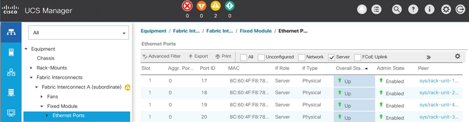
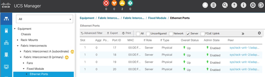
Server Discovery
As previously discussed, when the Fabric Interconnects server ports are configured and active, the HyperFlex servers connected to those ports will begin a discovery process. During discovery, the servers’ internal hardware inventories are collected, along with their current firmware revisions. Before starting the HyperFlex installation processes that configures the HyperFlex servers, wait for the servers to finish their discovery process and show up as unassociated servers with no errors.
To verify the discovery status of HyperFlex servers, follow these steps:
1. In Cisco UCS Manager, click the Equipment icon on the left-hand side, and click Equipment from the navigation tree on the left.
2. In the properties pane, click the Servers tab.
3. Click the Rack-Mount Servers sub-tab for HyperFlex servers to view the servers’ status in the Overall Status column.
Complete Cisco UCS Domain Setup in Site-B
Follow the procedures outlined in the Complete Cisco UCS Domain Setup in Site-A section to complete the UCS domain setup in Site-B setup using the setup information provided.
To verify the setup in Site-B, follow these steps:
1. Verify that the uplink ports in Site-B show as Network ports with an Overall Status of Up.
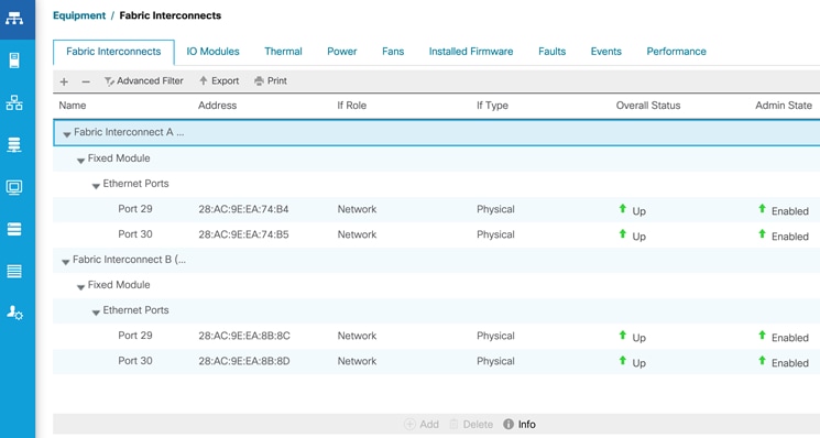
2. Verify that port channels in Site-B are up and running with Active members.
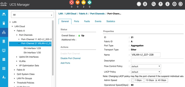
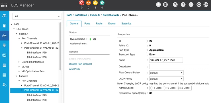
3. Verify that all ports connecting to HyperFlex servers are Server ports with an Overall Status of Up.
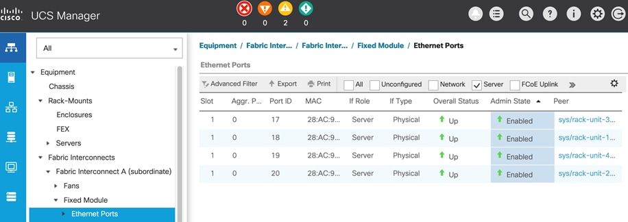
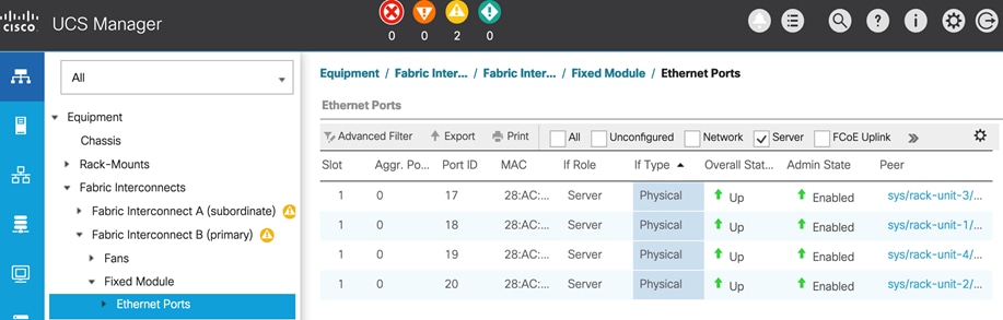
4. Wait for the server discovery process to complete and verify that the servers are in an Unassociated but in an Overall OK state before proceeding with HyperFlex installation.
Enable Cisco Intersight Management in Site-A
Cisco Intersight is a cloud-based management tool for unified management and orchestration of all Cisco UCS domains and HyperFlex systems regardless of where they are located. Cisco Intersight currently does not support the install of HyperFlex stretched clusters.
In this section, you will connect the two Cisco UCS domain in the solution to enable cloud-based management of both active-active sites from Cisco Intersight. Enterprises can now utilize the various orchestration and operations capabilities unique to Cisco Intersight.
The prerequisites for setting up access to Cisco Intersight are as follows.
● Account on cisco.com.
● A valid Cisco Intersight account. This can be created by navigating to https://intersight.com and following the instructions for creating an account. The account creation requires at least one device to be registered in Intersight, along with the Device ID and Claim ID from the device.
● Valid License on Cisco Intersight
● Cisco UCS Fabric Interconnects must have reachability to Cisco Intersight. In this design, the reachability is through an out-of-band network in the existing infrastructure.
● Cisco UCS Fabric Interconnects must be able to do a DNS lookup to access Cisco Intersight.
● Device Connectors on Fabric Interconnects must be able to resolve svc.ucs-connect.com.
● Allow outbound HTTPS connections (port 443) initiated from the Device Connectors on Fabric Interconnects to Cisco Intersight. HTTP Proxy is supported.
To enable cloud-based management of a Cisco UCS domain using Cisco Intersight, collect the following information from the Cisco UCS domain as outlined in the Deployment Steps section.
● Device ID
● Claim Code
To enable Cisco Intersight cloud-based management for a Cisco UCS domain, follow these steps:
1. Use a web browser to navigate to Cisco Intersight at https://intersight.com/.
2. Log in with a valid cisco.com account or single sign-on using your corporate authentication. Select Account that will be used to manage the Cisco UCS domain.
3. Use a web browser to navigate to the Cisco UCS Manager GUI. Log in using the admin account.
4. From the left navigation menu, select the Admin icon.
5. From the left navigation pane, select All > Device Connector.
6. In the right pane, click the Settings wheel icon and enable the Device Connector to enable Intersight management. Also, specify the level of access that is allowed. Configure HTTP Proxy, DNS, NTP and Certificate Manager as needed. Click Save to exit.
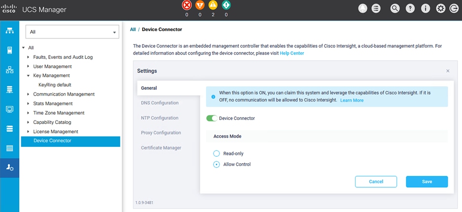
7. From the All/Device Connector, copy the Device ID and Claim ID information. This information will be required to add this device to Cisco Intersight.
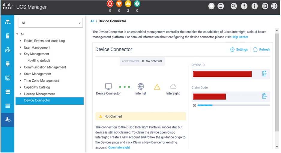
8. Navigate back to Cisco Intersight, select the Account to use, and go to ADMIN > Targets in the left navigation menu.
9. Click the Claim Target button in the top right-hand corner.
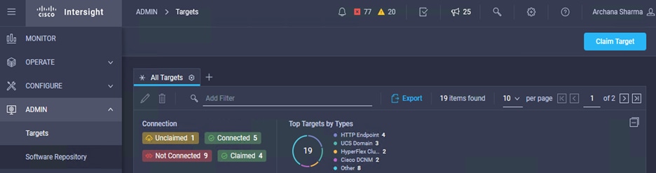
10. In the Select Target Type window, click on Cisco UCS Domain (UCSM Managed) to select it.
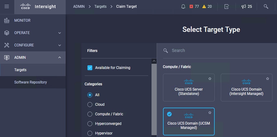
11. Click the Start button from the bottom right corner.
12. Paste the previously copied Device ID and Claim Code from Cisco UCSM. Click Claim.
13. On Cisco Intersight, the newly added UCS domain should now have a Status of Connected.
14. On Cisco UCS Manager, the Device Connector should now have a Status of Claimed.
Enable Cisco Intersight Management of Cisco UCS domain in Site-B
To enable Cisco Intersight cloud-based management of the Cisco UCS domain in Site-B, follow the procedures outlined in the previous section for Site-A.
Verify Cisco Intersight Management in Site-A and Site-B
Verify that Cisco UCS Domains in Site-A and Site-B are available in Cisco Intersight. Enterprises can now leverage the different orchestration and management capabilities available on the platform to manage multiple data centers and sites from the cloud.
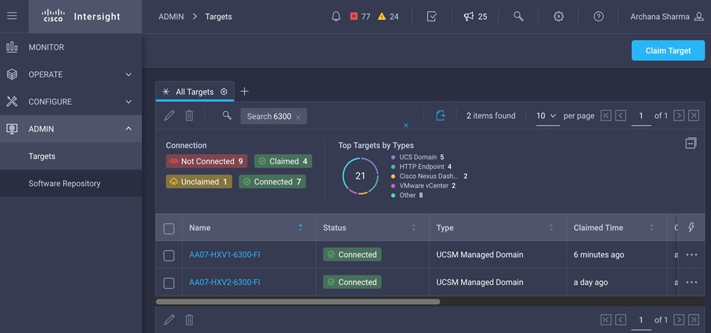
Setup VXLAN Fabric for HyperFlex – using HashiCorp Terraform
In this solution, Cisco DCNM is used to centrally deploy and manage the end-to-end Cisco VXLAN EVPN Multi-Site Fabric. Cisco DCNM’s Fabric Builder provides a GUI-driven mechanism for automating the Day-0 deployment of a VXLAN fabric – see Solution Design section of this document for more details. The centralized management of a VXLAN fabric using Cisco DCNM makes it easier to implement automation as it serves as a single point of integration for provisioning a large fabric such as the multi-site fabric used in this solution. Cisco DCNM provides REST APIs, Ansible modules and a DCNM Terraform Provider to programmatically manage a Cisco VXLAN fabric. The HashiCorp Terraform Provider for Cisco DCNM is used in this solution for Day-1 and Day-2 deployment activities such as adding ToR leaf switches to the fabric, establishing access layer connectivity to Cisco UCS and HyperFlex Infrastructure, and provisioning tenants and networks. By using a scriptable tool such as Terraform, customers can implement changes faster and with fewer errors. This approach is often referred to as Infrastructure as Code (IaC). The Terraform scripts and configuration files can be created and validated prior to deployment. They can be reused in multiple deployments or for repetitive tasks where deployment-specific configuration is captured in a variables file that can be easily modified to support new deployments. The scripts can also be maintained in a version control system (VCS) repository such as GitHub to maintain a historical record of changes for auditing purposes and to serve as a single source of truth for the different application and infrastructure environments that an Enterprise has to manage.
Cisco Intersight Service for Terraform
Cisco Intersight Service for Terraform (IST) is a service available in Cisco Intersight that enables Enterprises to centrally manage their IaC efforts from the cloud using Terraform Cloud for Business. IaC or other automation projects in Enterprises can quickly become distributed and unmanaged as multiple engineers develop and test their Terraform plans or scripts on personal laptops or Linux VMs that they built for their individual use. Having a centralized location such as Terraform Cloud for Business provides Enterprises with a single location to manage their automation efforts in both on-prem and hybrid cloud deployments. Terraform cloud integrates with VCS such as GitHub to store and maintain Terraform plans and provides a web-based portal that administrators and teams can use to manage and collaborate on projects, and generally improve manageability to IaC efforts within an Enterprise. Terraform Cloud can manage both on-prem and cloud-native systems to enable integrated orchestration and provisioning workflows. For example, Terraform Cloud for Business can be used with Cisco Intersight to implement changes on UCS and HyperFlex, and also use Cisco IST to make changes to the on-prem networking, using the Terraform Provider for the networking element such as the Terraform Provider for Cisco DCNM. Cisco IST enables Terraform Cloud for Business to access and provision on-premise infrastructure from the cloud. Without Cisco IST, a Terraform agent would need to be deployed on-prem with access to all systems that Terraform needs to provision. The agent now becomes yet another administrative task that the Enterprise has to manage on an ongoing basis. Cisco IST prevents this by automating the deployment and management of the Terraform cloud agent by running it on a Cisco Intersight Assist appliance that you may already be using. Cisco Intersight Assist is an on-prem component that Enterprises can add to facilitate managing systems and resources that are not native to Cisco Intersight such as VMware vCenter.
The solution uses Terraform plans to provision the VXLAN fabric to support HyperFlex inter-cluster communication within and across two data center sites. Terraform plans use the Terraform provider for Cisco DCNM to provision the end-to-end VXLAN fabric. The plans can be executed on a local, on-prem workstation or from Terraform Cloud using Cisco IST. Cisco IST is required since Cisco DCNM is an on-prem element that is not reachable from the cloud. Enterprises do not have to manage the Terraform Cloud Agent as Cisco IST handles all lifecycle management. The high-level architecture of Cisco IST and integration with Terraform Cloud is shown in Figure 45.
Figure 45. Cisco Intersight Service for Terraform Architecture
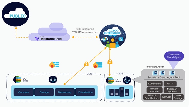
Figure 46 illustrates using Cisco IST to manage on-premise resources.
Figure 46. Terraform Cloud for On-Prem Resources using Cisco IST
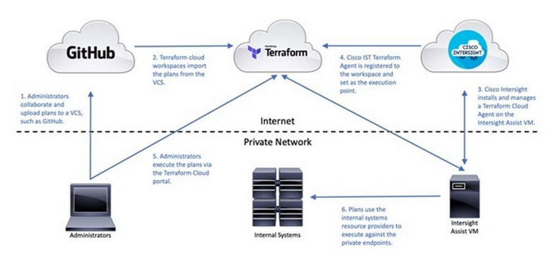
For more information on Cisco Intersight Service for Terraform, see: https://www.cisco.com/c/en/us/products/collateral/cloud-systems-management/intersight/nb-06-intersight-terraf-ser-aag-cte-en.html
Requirements
The requirements for using Cisco IST are outlined below:
● License for Hashicorp Terraform Cloud for Business
● Cisco Intersight Advantage or Premier License
● Operational Cisco Intersight Assist Virtual Appliance
● Operational Terraform Cloud Agent
For more information on deploying Cisco Intersight Assist and Terraform Cloud Agent, see the References section of this document. When the above requirements are in place, the Terraform cloud agent can be added in Terraform Cloud and a new or existing workspace can be provisioned to use the new agent. Any Terraform plans in the workspace will now be executed on the Cisco IST cloud agent to provision resources within the Enterprise datacenter.
Provision VXLAN Fabric using Hashicorp Terraform
As stated earlier, Terraform plans can be executed on a local workstation using local files, or they can be executed from Terraform Cloud, integrated with a VCS such as GitHub where the scripts are stored and maintained. In this solution, Terraform plans were executed from a local workstation.
Prerequisites
The setup required to use Terraform plans to provision the VXLAN fabric to support a new HyperFlex stretch cluster deployment requires:
● Local management workstation to execute the plans, with access to Cisco DCNM
● Working installation of Terraform on the local management workstation. A guide for getting started with HashiCorp Terraform can be found at the following link: https://learn.HashiCorp.com/terraform.
● Working installation of GitHub on the local management workstation, with access to the Cisco UCS Compute Solutions public repository: https://github.com/ucs-compute-solutions.
● The Terraform scripts used in this solution can be cloned from the public repository, located at the following link: https://github.com/ucs-compute-solutions/HyperFlex-VXLAN-Projects Alternatively, the example scripts can be modified and copied to a GitHub repository and then linked to a Terraform Cloud workspace to execute the plans from Terraform Cloud. The workspace is configured to use the Cisco Intersight Service for Terraform agent, which will execute the plans. The examples in this document use a local workstation to execute the Terraform plans.
Clone GitHub Collection
The first step in the process is to clone the GitHub collection named "HyperFlex-VXLAN-Projects" to a new empty folder on the management workstation. Cloning the collection creates a local copy, which is then used to run the playbooks that have been created for this solution. To clone the GitHub collection, follow these steps:
1. From the management workstation, create a new folder for the project. The GitHub collection will be cloned in a new folder inside this one, named HyperFlex-VXLAN-Projects.
2. Open a command-line or console interface on the management workstation and change directories to the new folder just created.
3. Clone the GitHub collection using the following command:
git clone https://github.com/ucs-compute-solutions/HyperFlex-VXLAN-Projects.git
4. Change directories to the new folder named HyperFlex-VXLAN-Projects.
Modify Terraform Variables
The scripts used in this solution contains multiple Terraform plans in a folder named HXV-SC-VXLAN-MS. The plans, have names with numbers starting from ‘0’ to indicate the relative order of the plan in the overall provisioning workflow.
Terraform uses variables like other scripting tools and languages in order to set temporary values for each execution of the plan. The variables are defined in the file named variables.tf, and their values are set in the file named variables.auto.tfvars. For provisioning a VXLAN Multi-Site fabric supporting a Cisco HyperFlex stretched cluster using the Cisco DCNM Terraform Provider, the included variables.auto.tfvars file can be modified, or copied using a new file name and referenced with each execution of the script.
To modify the required variable file(s), follow these steps:
1. On the management workstation, save a copy of the variables.tfvars and variables.auto.tfvars file using a new name, for example, variables.tfvars.bkup and variables.auto.tfvars.bkup. Delete the existing variables.auto.tfvars file.
2. Using either the command line or a graphical file editor, modify the existing variables.tfvars file with the values for configuring the VXLAN fabric to support the Cisco HyperFlex Stretch Cluster VSI being deployed. Rename this file to indicate the specific environment where the plan is being used especially if it will be used for multiple deployments.
3. If using multiple files, then using either the command line or a graphical file editor, modify the new individual *.tfvars files with the values for the necessary variables to configure the VXLAN fabric to support the Cisco HyperFlex Stretch cluster to be installed.
Variable File Details
The variables in the variables.auto.tfvars file are listed in the tables below with a description. The .tfvars file is included in the GitHub repository with the Terraform plans. The values should be modified as appropriate to meet the needs of your deployment.
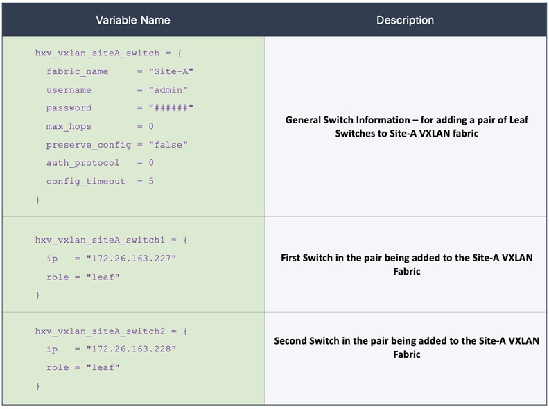
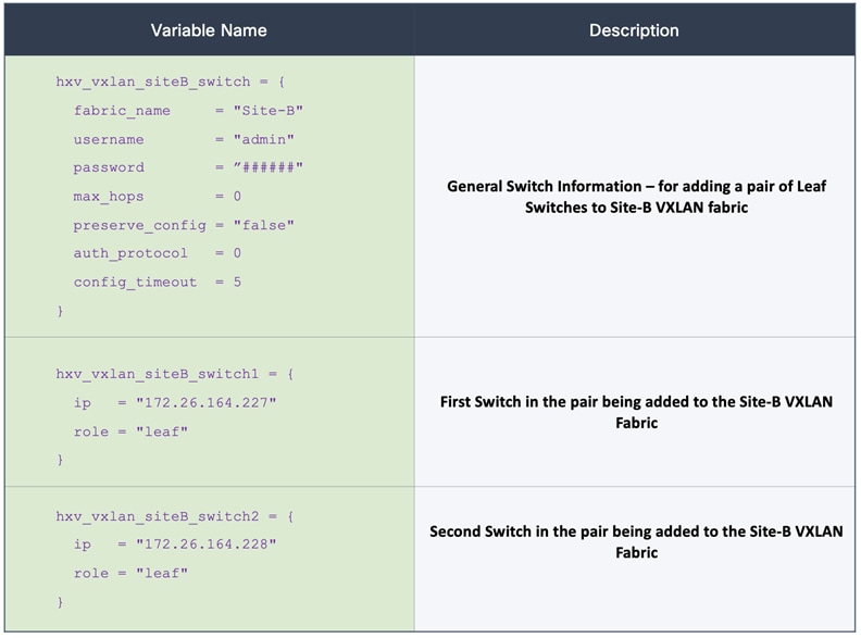
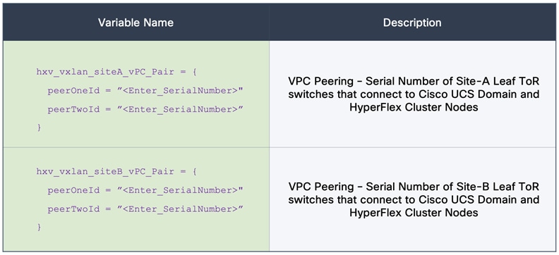
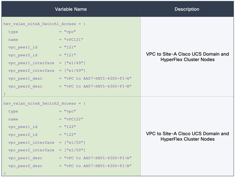
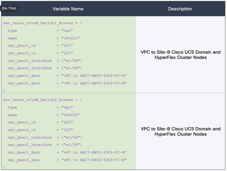
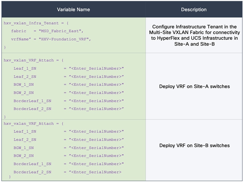
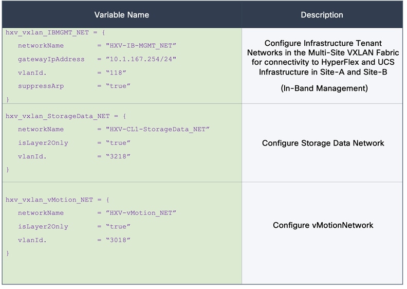
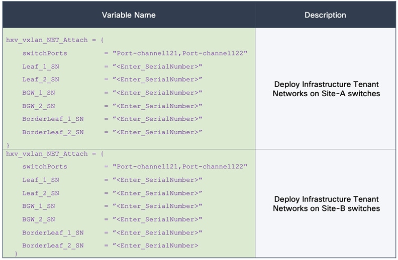
Execute Terraform Scripts/Plans
Once the Terraform plans have been defined, the Terraform plans or scripts can now be executed. Terraform has 4 main verbs; init, plan, apply and destroy. The init verb performs an initial environment setup, plan examines the script to determine which actions will be taken, apply executes the script, while destroy can be used to remove the resources that were created.
Terraform Init
The init command initializes the Terraform environment to execute the plan/script. Any provider modules, such as the Cisco DCNM provider, are downloaded and all prerequisites are checked. This initialization only needs to be run once per plan, with subsequent runs only executing and applying the plan. To initialize the environment via CLI, go to the HyperFlex-VXLAN-Projects folder where the GitHub repository was cloned, and run:
terraform init
Terraform Plan
The plan command is used to evaluate the Terraform script for any syntax errors or other problems. The script will be evaluated against the existing environment and a list of planned actions will be shown. If there are no errors and the planned actions appear correct, then it is safe to proceed to running the apply command in the next step. To evaluate the Terraform plan via CLI, go to the HyperFlex-VXLAN-Projects folder where the GitHub repository was cloned, and run:
terraform plan <First TF Plan>
terraform plan <Second TF Plan>
…
Terraform Apply
The final step is to apply the new configuration. This command will repeat the planning phase and ask for confirmation to continue with creating the new resources. To run the Terraform plan via the CLI, go to the HyperFlex-VXLAN-Projects folder where the GitHub repository was cloned, and run:
terraform apply <First TF Plan>
terraform apply <Second TF Plan>
…
Because the configuration is divided into multiple scripts, terraform plan and terraform apply must
be run multiple times to step through the configuration carefully, at least the first time it is being executed. After applying the Terraform plans, monitor the status of the tenant via Cisco DCNM. It may take several minutes for the settings to propagate and for the tenant to be marked as fully healthy.
The VXLAN fabric should now be provisioned to support the HyperFlex cluster installation process – verify connectivity before proceeding with the installation.
Install HyperFlex Stretched Cluster - using HyperFlex Installer VM
In this section, the installation of a (4+4) node HyperFlex stretched cluster is explained. This cluster is deployed using an on-premise installer. Cisco Intersight currently does not support the installation of HyperFlex stretched clusters. As stated earlier, the HyperFlex stretched cluster is intended for mission critical applications and workloads that require the resiliency provided by an active-active solution. As such, it will also be referred to as the Applications Cluster in this document.
The HyperFlex installer virtual machine will configure Cisco UCS policies, templates, service profiles, and settings, as well as assigning IP addresses to the HyperFlex servers that come from the factory with ESXi hypervisor software preinstalled. The installer will deploy the HyperFlex controller virtual machines and software on the nodes, add the nodes to VMware vCenter managing the HyperFlex Cluster, and finally create the HyperFlex cluster and distributed filesystem. The setup is done through a deployment wizard.
Deployment Overview
The deployment of a HyperFlex stretched cluster that the spans two active-active sites consists of the following high-level steps, automated by the HyperFlex Installer or Wizard, except for the Witness OVA deployment and the post-install steps (script):
● Configure Site-A (Wizard)
● Configure Site-B (Wizard)
● Deploy Witness Virtual Machine in a third Site (OVA)
● Create Cluster (Wizard)
● Verify Setup
The prerequisites for installing a HyperFlex stretched cluster are listed below:
1. Reachability from HyperFlex Installer to the out-of-band management interfaces on the Cisco UCS Fabric Interconnects in each site.
2. Reachability from HyperFlex Installer to the out-of-band management (CIMC) interfaces of the servers in each site, reachable via the Fabric Interconnects’ management interfaces. This network (ext-mgmt) should be in the same subnet as the Fabric Interconnect management interfaces.
3. Reachability from HyperFlex Installer to the ESXi in-band management interface of the HyperFlex nodes in each site (when ESXi setup is complete during the installation process).
4. Reachability from HyperFlex Installer to the VMware vCenter Server that will manage the HyperFlex cluster(s) being deployed.
5. Reachability from HyperFlex Installer to the AD/DNS server(s) for use by the HyperFlex cluster being installed.
6. Reachability from HyperFlex Installer to the NTP server(s) for use by the HyperFlex cluster being installed.
7. Reachability from VMware vCenter to ESXi nodes and HyperFlex Storage Controller Virtual Machines (SCVM) in both sites via the HyperFlex Management network.
8. Reachability from HyperFlex Witness (when the VM is deployed during the installation process) to HyperFlex cluster nodes (ESXi, SCVM) in both sites via the HyperFlex Management network.
9. Reachability to NTP and AD/DNS services from HyperFlex cluster nodes (ESXi, SCVM) in both sites via the HyperFlex Management network.
10. Reachability between HyperFlex cluster nodes (ESXI, SCVM) in each site via the HyperFlex Management network.
11. Reachability between HyperFlex cluster nodes (ESXI, SCVM) in each site via the HyperFlex Storage Data network.
12. Enable the necessary ports to install HyperFlex. For more information, see Networking Ports section in Appendix A of the HyperFlex Hardening Guide: https://www.cisco.com/c/dam/en/us/support/docs/hyperconverged-infrastructure/hyperflex-hx-data-platform/HX-Hardening_Guide_v3_5_v12.pdf
13. Review the Pre-installation Checklist for Cisco HX Data Platform: https://www.cisco.com/c/en/us/td/docs/hyperconverged_systems/HyperFlex_HX_DataPlatformSoftware/HyperFlex_Preinstall_Checklist/b_HX_Data_Platform_Preinstall_Checklist.html
The reachability requirements in the above list must be verified before the install process starts. The VXLAN EVPN Multi-Site fabric provides the network connectivity between the components in the different HyperFlex infrastructure networks (management, storage data, vMotion) to bring the cluster online, and for Application VM networks, once the cluster is operational. The VXLAN EVPN Multi-Site Fabric must therefore be setup before starting the HyperFlex installation process.
The setup information to install a HyperFlex stretched cluster in this design is provided below:
● Installer VM IP Address: 10.99.167.248 (root/Cisco123)
● VMware vCenter VM IP Address: 10.99.167.240
● HyperFlex Witness VM IP Address: 10.99.167.249
Site-A Information
Table 8. Cisco UCSM Credentials (Site-A)
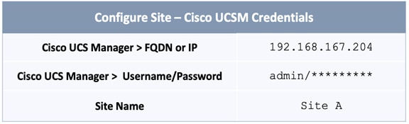
Table 9. Cisco UCSM - Infrastructure VLANs (Site-A, Site-B)
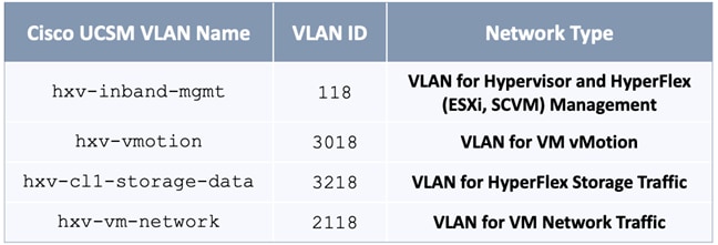
Table 10. Cisco UCSM Configuration (Site-A)
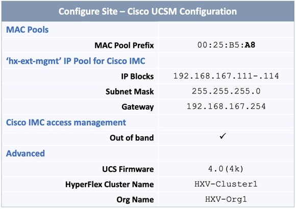
Table 11. Hypervisor Configuration (Site-A)
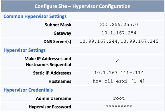
Site B Information
Table 12. Cisco UCSM Credentials (Site-B)
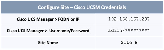
Table 13. Cisco UCSM – Infrastructure VLANs (Site-A, Site-B)
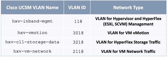
Table 14. Cisco UCSM Configuration (Site-B)

Table 15. Hypervisor Configuration (Site-B)
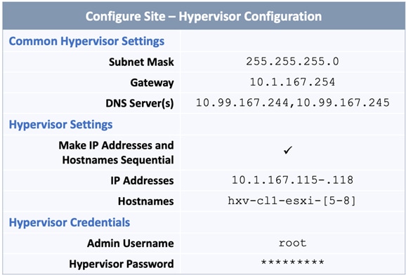
Cluster Information
Table 16. Cluster – Credentials
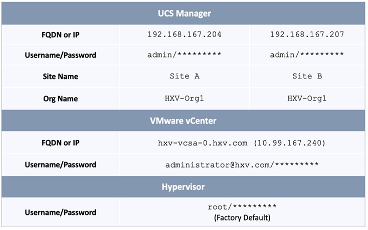
Table 17. Cluster - Subnets and IP Addresses
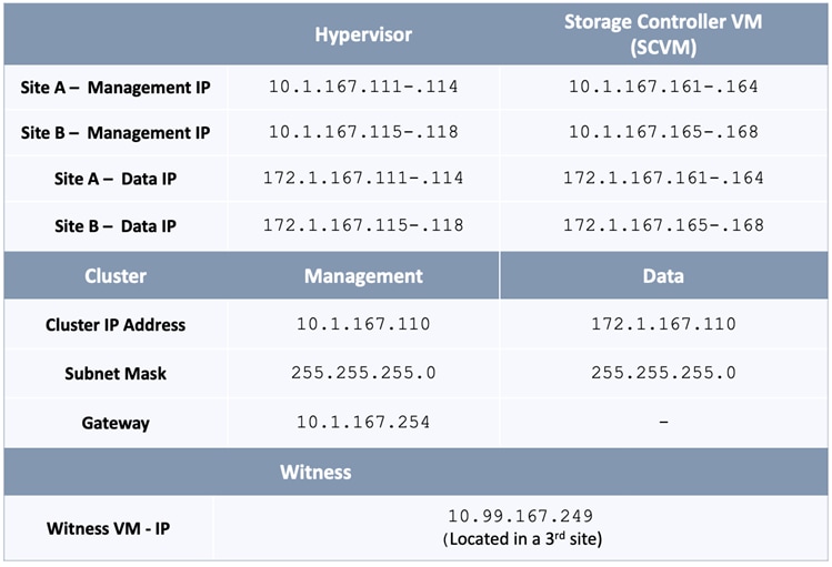
Table 18. Cluster Configuration
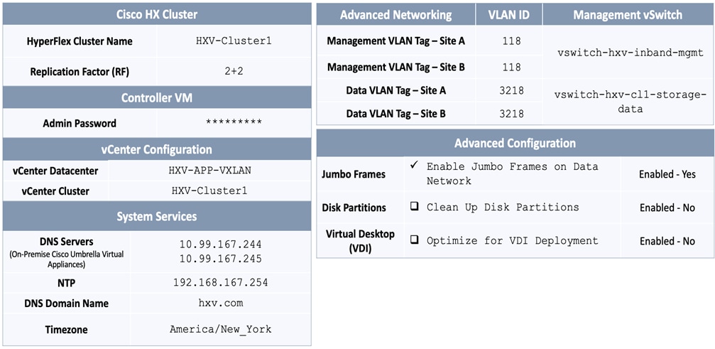
To deploy a HyperFlex stretched cluster across two active-active sites interconnected by an VXLAN EVPN Multi-Site fabric, follow the procedures detailed in this section.
Verify Server Status in Site A and Site B before HyperFlex Installation
Before starting the HyperFlex installation process that will create the service profiles and associate them with the servers, you must verify that the servers in both Cisco UCS domains have finished their discovery process and are in the correct state.
To verify the server status in Site A and Site B, follow these steps:
1. Use a browser to navigate to the Cisco UCS Manager in the first HyperFlex stretched cluster site (Site A). Log in using the admin account.
2. From the left navigation pane, click the Equipment icon.
3. Navigate to All > Equipment. In the In the right windowpane, click the Servers tab.
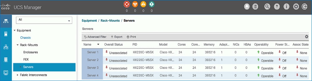
4. For the Overall Status, the servers should be in an Unassociated state. The servers should also be in an Operable state, powered Off and have no alerts with no faults or errors.
5. Repeat steps 1 - 4 for the Hyperflex nodes and Cisco UCS Manager in the second HyperFlex stretched cluster site (Site B).
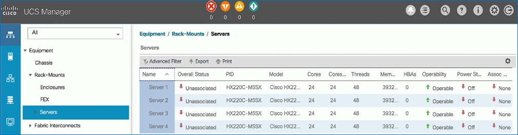
6. The servers in both sites are now ready to begin the HyperFlex stretch cluster installation process.
Connect to the HyperFlex Installer
To access the HyperFlex installer virtual machine, follow these steps:
1. Use a web browser to navigate to the IP address of the installer virtual machine. Click accept or continue to bypass any SSL certificate errors.
2. At the login screen, enter the username and password. The default username is: root. Password is either the default password (Cisco123) or whatever it was changed to after the OVA was deployed. Check the box for accepting terms and conditions. Confirm the installer version – see lower right-hand corner of the login page.
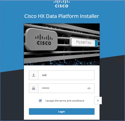
3. Click Login.
4. You should now be forwarded to the HyperFlex Installer Workflow page where you can install a new Standard Cluster, Stretch Cluster, Edge Cluster or expand an existing cluster. In this solution, the installer virtual machine is used to deploy a HyperFlex stretched cluster.
Configure Site A using HyperFlex Deployment Wizard
To configure the first site (Site A) in the stretched cluster, use the Setup Information to complete the following steps:
1. From the HyperFlex Installer/Configuration Workflow page, for the Select a Workflow, click Create Cluster and from the drop-down list, select Stretch Cluster.
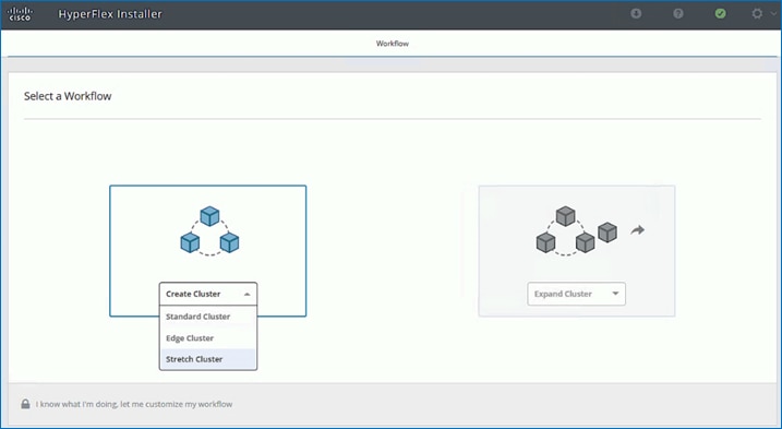
2. In the Credentials screen, select the radio button for Configure Site. Use the setup information to configure the Cisco UCSM Credentials for Site A. The site name will be the name of the physical site in Cisco HyperFlex Connect used to manage the cluster. It also corresponds to the first data center site in the active-active solution. If you have a JSON configuration file saved from a previous attempt to configure Site A, you may click Select a File from right side of the window to select and load a JSON file. Click Use Configuration to populate the fields for configuring this site. The installer does not save passwords.
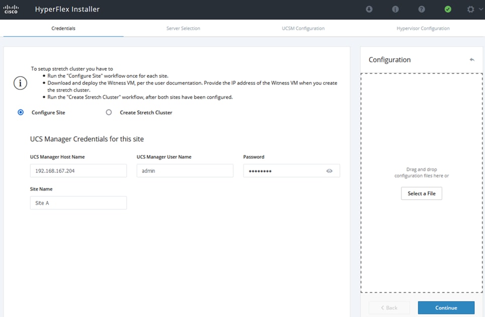
3. Click Continue.
4. In the Server Selection screen, select the unassociated servers in Site A that should be part of the stretched cluster.
![]() The Fabric Interconnect ports that connect to HyperFlex servers were enabled in the Solution Deployment – Setup Cisco UCS Domains section. You can also choose to enable it here by clicking on Configure Server Ports at the top. However, the servers will go through a discovery process that takes a significant amount of time and you will not have control of the server number order.
The Fabric Interconnect ports that connect to HyperFlex servers were enabled in the Solution Deployment – Setup Cisco UCS Domains section. You can also choose to enable it here by clicking on Configure Server Ports at the top. However, the servers will go through a discovery process that takes a significant amount of time and you will not have control of the server number order.
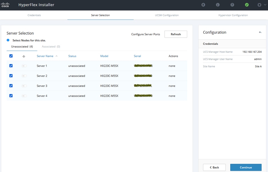
5. Click Continue.
6. In the UCSM Configuration section of the workflow, use the Setup Information to configure the parameters for Site A.
![]() The installer will create a VMware vSwitch for Guest Virtual Machines by default. The VM networks can be migrated to a VMware vDS after the install. At least one VLAN/networks for the Guest VMs must be specified during the install process so that configuration to support VM networks can be provisioned in the Cisco UCS Manager. For example, vNIC Templates, vNICs, QoS policies and so on.
The installer will create a VMware vSwitch for Guest Virtual Machines by default. The VM networks can be migrated to a VMware vDS after the install. At least one VLAN/networks for the Guest VMs must be specified during the install process so that configuration to support VM networks can be provisioned in the Cisco UCS Manager. For example, vNIC Templates, vNICs, QoS policies and so on.
7. The specified VLAN Names and VLAN IDs will be created on Cisco UCS. Multiple VLAN IDs can be specified for the (guest) virtual machine networks.
8. The MAC Pool prefix, specifically the 4th byte must be unique.
9. The ‘hx-ext-mgmt’ IP Pool for Cisco IMC must be unique. It is used by the CIMC interfaces on HyperFlex servers in the UCS domain.
10. The UCS Firmware Version provides a drop-down list of the versions currently available on Site A UCS.
11. The HyperFlex Cluster Name should be the same in both sites since they are part of a single cluster. The Org Name can be the same if the stretched cluster sites are in different UCS domains.
![]() When deploying additional clusters in the same UCS domain, change VLAN names (even if the VLAN IDs are same), MAC Pool prefix, Cluster and Org Names so as to not overwrite the original cluster.
When deploying additional clusters in the same UCS domain, change VLAN names (even if the VLAN IDs are same), MAC Pool prefix, Cluster and Org Names so as to not overwrite the original cluster.
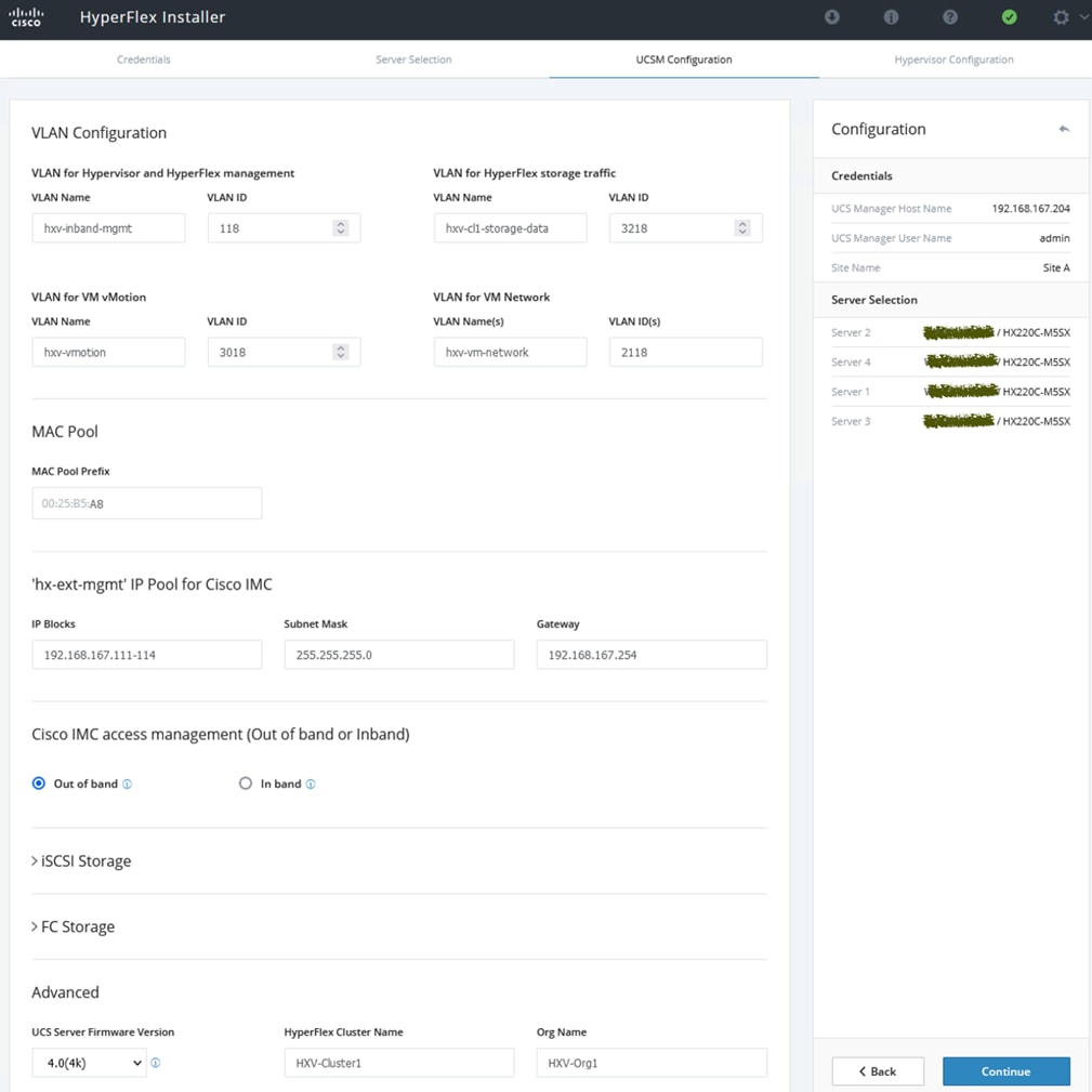
12. Click Continue.
13. In the Hypervisor Configuration screen, use the Setup Information to configure the parameters for ESXi hosts in Site A. The default Hypervisor credentials for factory-installed nodes are: root with a password of Cisco123. The IP addresses will be assigned to the ESXi hosts via Serial over Lan (SoL) from Cisco UCS Manager.
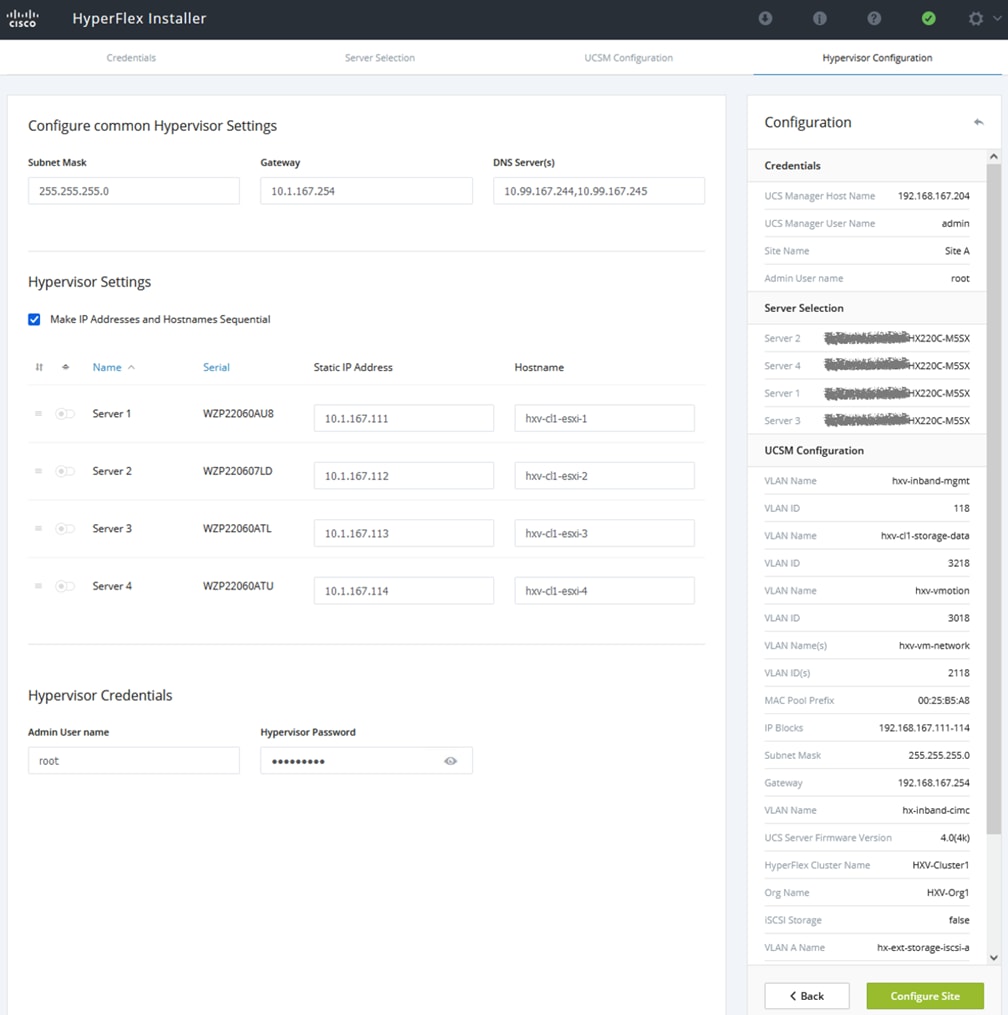
14. Click Configure Site to start configuring Site A. The wizard will step through the configuration stages and provide the status for specific configuration completed as shown below:
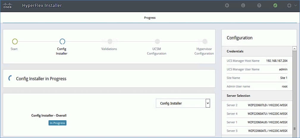
If the configuration is successful, you will see a screen similar to the one shown below:
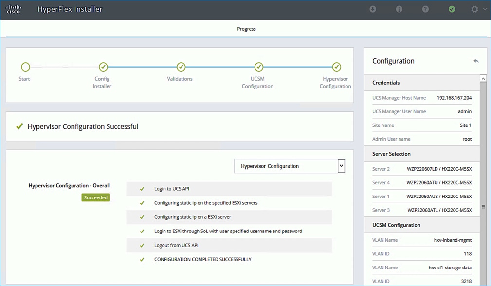
15. Export the Site A configuration by clicking the down arrow icon in the top right of the screen. Click OK to save the configuration to a JSON file. This file can be used to rebuild the same cluster in the future, and as a record of the configuration options and settings used during the installation.

16. Proceed to the next section to Configure Site B.
Configure Site B using HyperFlex Deployment Wizard
To configure the second site (Site B) in the stretched cluster, repeat the procedures in the previous section for Site A using the Setup Information for Site B. Complete by saving the JSON configuration file. Proceed to the next section to Deploy Witness Virtual Machine in a third site.
Deploy HyperFlex Witness Virtual Machine
A HyperFlex stretched cluster requires a HyperFlex Witness to achieve quorum in the event of a site failure or split-brain scenario. The Witness should be deployed in a third site with reachability to all nodes (both sites) in the cluster. In this design, the Witness is deployed on existing infrastructure outside the VXLAN Multi-Site Fabric and reachable via the external connectivity provided by the fabric in each site.
Table 19. Setup Information
| Witness VM - IP Address |
10.99.167.249/24 |
| Gateway |
10.99.167.254 (external to the Fabric) |
| DNS |
10.99.167.244, 10.99.167.245 |
| NTP |
192.168.167.254 |
To deploy the Witness virtual machine for the HyperFlex stretched cluster, follow these steps:
1. Use a browser to navigate to the VMware vCenter server that will be used to deploy the Witness.
2. Click the vSphere Web Client of your choice. Log in using an Administrator account.
3. From the vSphere Web Client, navigate to Home > Hosts and Clusters.
4. From the left navigation pane, select the Datacenter > Cluster and right-click to select Deploy OVF Template….
5. In the Deploy OVF Template wizard, for Select Template, select Local file and click the Browse button to locate and open the HyperFlex-Witness-1.1.1.ova file, click the file and click Open. Click Next.
6. Modify the VM name to be created (optional). Click a folder location to place the VM. Click Next.
7. Click a specific host or cluster to locate the virtual machine. Click Next.
8. After the file validation, review the details. Click Next.
9. Select a Thin provision virtual disk format, and the datastore to store the VM. Click Next.
10. Modify the network port group selection from the drop-down list in the Destination Networks column, choosing the network the witness VM will communicate on. Click Next.
11. Enter the static address settings to be used, fill in the fields for the Witness Node’s IP Address and Mask, DNS server, Default Gateway, and NTP Server info.
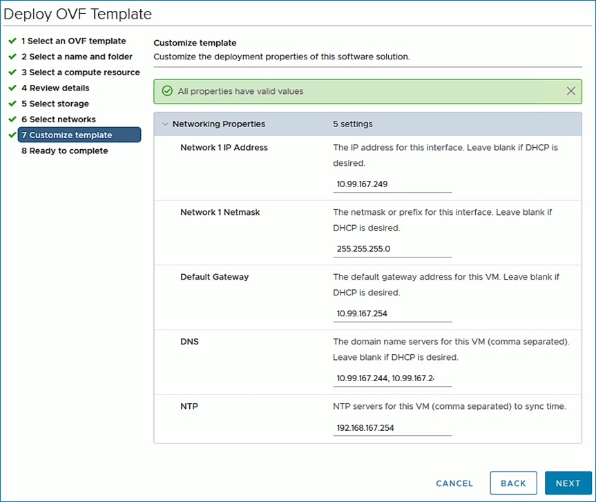
12. Click Next.
13. Review the final configuration and click Finish. The witness VM will take a few minutes to deploy, once it has deployed, power on the new VM.
14. Proceed to the next section to create a stretch HyperFlex cluster.
Create Stretch Cluster using Deployment Wizard
To create a stretched cluster that spans Site A and Site B, use the Setup Information provided to complete the following steps:
1. From the HyperFlex Installer GUI, go to the wheel icon in the top right of the window and select Create Stretch Cluster from the drop-down list.
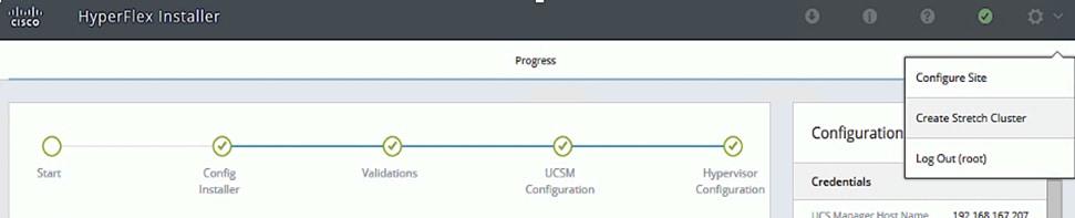
2. In the Credentials screen, select the radio button for Create Stretch Cluster. For Site A and Site B, provide the credentials using the Setup Information provided earlier.
![]() If you have a JSON configuration file saved from a previous attempt for Create Stretch Cluster, you may click Select a File from the box on the right side of the window to select the JSON configuration file and click Use Configuration to populate the fields for configuring this site. The installer does not save passwords.
If you have a JSON configuration file saved from a previous attempt for Create Stretch Cluster, you may click Select a File from the box on the right side of the window to select the JSON configuration file and click Use Configuration to populate the fields for configuring this site. The installer does not save passwords.
3. Click Continue.
4. In the Server Selection screen, select the servers from Site A and Site B that should be part of the stretched cluster.
5. Click Continue.
6. In the IP Addresses screen, use the Setup Information to configure the parameter.
![]() A default gateway is not required for the data network, as those interfaces normally will not communicate with any other hosts or networks, so the subnet can be non-routable, Layer 2 network.
A default gateway is not required for the data network, as those interfaces normally will not communicate with any other hosts or networks, so the subnet can be non-routable, Layer 2 network.
7. Click Continue.
8. In the Cluster Configuration screen, use the Setup Information to configure the parameters.
9. Click Start to start the creation of the stretched cluster. The wizard will step through the configuration stages and provide status for each stage. If the configuration is successful, you will see a screen similar to the one below:
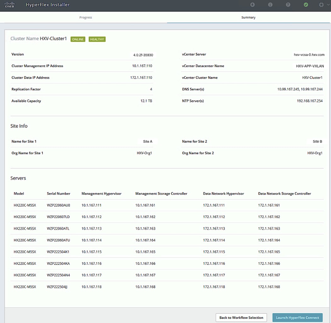
10. Export the cluster configuration by clicking the down arrow icon in the top right of the screen. Click OK to save the configuration to a JSON file. This file can be used to rebuild the same cluster in the future, and as a record of the configuration options and settings used during the installation.
11. Proceed to the next section to complete the post-installation tasks.
Post-Installation Tasks
Run Post-Install Script
Once the HyperFlex stretched cluster install completes, run the post_install script to finish the configuration before deploying any workloads. The script is executed from the HyperFlex Controller VMs.
● License the hosts in VMware vCenter
● Enable HA/DRS on the cluster in VMware vCenter
● Suppress SSH/Shell warnings in VMware vCenter
● Configure vMotion in VMware vCenter
● Enables configuration of additional guest VLANs/port-groups
● Perform HyperFlex Health check
● Send test Auto Support (ASUP) email if enabled during the install process
To run the post-installation script, follow these steps:
1. SSH into a HyperFlex Controller VM’s Management IP using the admin (or root) account.
2. Verify the cluster is online and healthy using stcli cluster info or the command below:
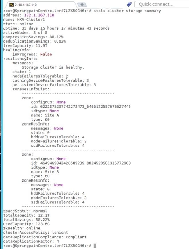
3. Run the following command to execute the post-install script:
/usr/share/springpath/storfs-misc/hx-scripts/post_install.py
4. Select workflow “1” for New/Existing Cluster.
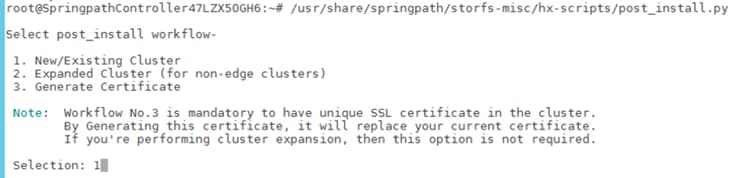
5. Follow the on-screen prompts to complete the post-install configuration as outlined below.
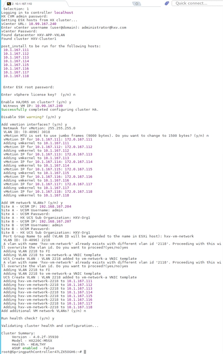
Additional Post-Install Tasks
This section explains the additional post-install tasks that must be completed prior to going into production.
Enable Smart Licensing
To enable licensing for the newly deployed HyperFlex stretched cluster, follow the procedures outlined below. HyperFlex 2.5 and later utilizes Cisco Smart Licensing, which communicates with a Cisco Smart Account to validate and allocate HyperFlex licenses from a pool of licenses available in the account. A HyperFlex cluster is installed with Smart Licensing enabled but the HyperFlex cluster will be in an unregistered, evaluation mode with a temporary 90-day evaluation period as shown below.
To activate and configure smart licensing, follow these steps:
1. Navigate to Cisco Software Central (https://software.cisco.com/) and log in to your Smart Account. From Cisco Smart Software Manager, generate a registration token.
2. In the License pane, click Smart Software Licensing to open Cisco Smart Software Manager.
3. Click Inventory.
4. From the virtual account you want to use to register the cluster, click General > New Token.
5. In the Create Registration Token dialog box, add a Description, enter the number of days you want the token to be active and available to use, and check Allow export controlled function.
6. Click Create Token.
7. From the New ID Token row, click the Actions drop-down list, and click Copy.
8. SSH into a HyperFlex Controller VM. Log in using the admin/root account.
9. Register your HX storage cluster, where idtoken-string is the New ID Token from Cisco Smart Software Manager.
stcli license register --idtoken idtoken-string 12
10. Confirm that the HyperFlex cluster is registered.
stcli license show summary
11. The cluster is now licensed and ready for production deployment.
Enable Syslog
To prevent the loss of diagnostic information when a host fails, ESXi logs should be sent to a central locations such as VMware vCenter server or a syslog server. Use a multi-exec tool (for example, MobaXterm) to simultaneously execute commands on all servers in the cluster as shown below.
To configure syslog on ESXi hosts, follow these steps:
1. SSH into the ESXi hosts as root user.
2. Enter the commands shown below, using the IP address IP address of the vCenter or the syslog server that will receive the syslog logs.
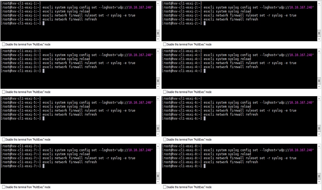
Enable/Disable Auto-Support and Notifications
Auto-Support is enabled if specified during the HyperFlex installation. Auto-Support enables Call Home to automatically send support information to Cisco TAC and notifications of tickets to the email address specified. Auto-Support and Notifications settings can be changed from HyperFlex Connect.
To configure Auto-Support and Notifications Settings, follow these steps:
1. Use a browser to navigate to HyperFlex Connect HTML management web page using the Management IP of the Cluster. Log in using the admin account.
2. Click the gear shaped icon in the upper right-hand corner and click Auto-Support Settings.
3. Enable or Disable Auto-Support as needed. Enter the email address to receive notifications for Auto-Support events.
4. Enable or Disable Remote Support as needed. Remote support allows Cisco TAC to connect to the cluster and accelerate troubleshooting efforts.
5. If a web proxy is used, specify the settings for web proxy. Click OK.
6. To enable email notifications, click the gear shaped icon in top right corner, and click Notifications Settings.
7. Enter the Outgoing Mail Server information, the From Address and the Recipient List. Click OK.
Create Datastores with Site Affinity
Unlike HyperFlex standard and edge clusters, datastores created on HyperFlex stretched clusters must specify a Site Affinity. With datastore affinity, when a virtual machine is deployed on a given datastore, the VM’s virtual disk files (primary copy) will be stored on nodes in the same site as the datastore’s site affinity. Storage access is optimized by ensuring that all requests to read data from a datastore will be serviced by the nodes in the same site as the datastore’s site affinity, rather than by nodes in a remote site. Writes to a datastore in a HyperFlex stretch cluster will still incur inter-site latency as all copies have to be committed to both sites (2+2) before it can be acknowledged. Stretched clusters use a Replication Factor (RF) of 4, with 2 copies written to each site. A datastore created on HyperFlex stretched cluster are available on all nodes in the cluster.
Enterprises should implement the following best-practices to maximize performance:
● Create two datastores, one for each site. For example, HXV-APP-DS1 and HXV-APP-DS2 with affinity for Site A and B respectively.
● When deploying virtual machines in a site, use datastores with the same site-affinity as the VM so that the reads will be from local nodes rather than remote nodes.
To deploy a new datastore with site-affinity, follow these steps:
1. Use a browser to navigate to HyperFlex Connect HTML management web page using the Management IP of the Cluster. Log in using the admin account.
2. From the left navigation menu, select Manage > Datastores. Click the Create Datastore icon at the top.
3. In the Create Datastore pop-up window, specify a Name, Size and Site Affinity for the datastore.
4. Click Create Datastore to create the first datastore with site-affinity for the first site.
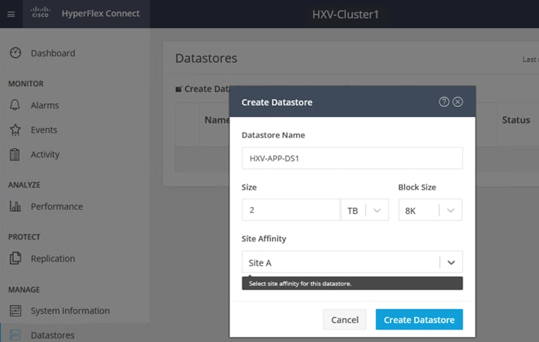
5. Repeat steps 1 - 4 to create a second datastore with site-affinity for the second site.
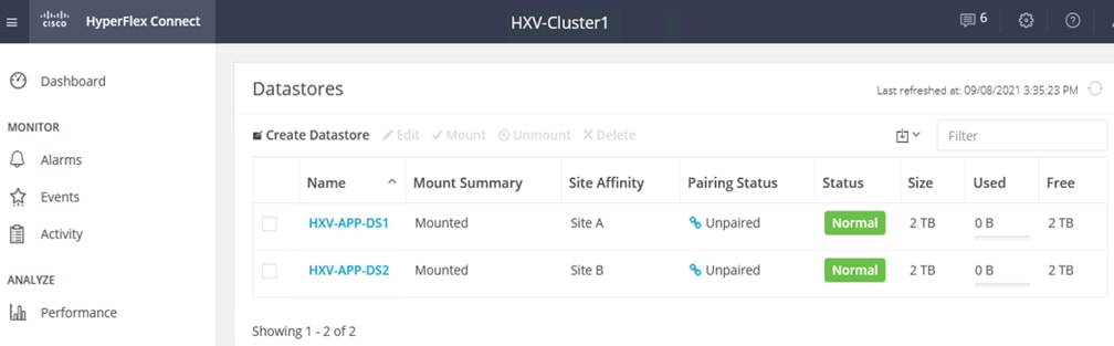
Verify Virtual Machine Site Affinity
HyperFlex uses site-affinity to create VMware Dynamic Resource Scheduler (DRS) affinity rules that will determine the placement of virtual machines on nodes in the cluster. The vSphere DRS affinity rules enable the stretched cluster to operate in an optimal manner. HyperFlex Installer creates the site affinity rules and groups during the cluster installation process. When virtual machines are deployed, they are automatically placed into a virtual machine group for the site. Under normal conditions, site affinity rules constrain the virtual machines to run in a given primary site (primary). If the primary site fails, the virtual machines will restart and failover to nodes to a secondary site. The virtual machines can be active in both data center sites, while providing failover if a site fails. The installer created Host Groups and Virtual Machine Groups for each site are shown below.
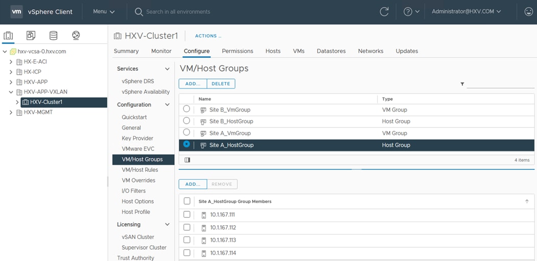
Implement VMware vSphere Best Practices
The failover of VMs between data centers or within a data center requires VMware vSphere High Availability (HA) to be implemented correctly as outlined earlier in the document.
Migrate Virtual Networking to VMware vDS (Optional)
Guest VM networks on the Applications cluster can optionally be migrated to a VMware vDS rather than using the installer created VMware vSwitch but use the uplinks from the vSwitch created for VM networks. This will prevent you from having to reconfigure the Cisco UCS side. To convert, follow the procedures detailed in this document: https://www.cisco.com/c/dam/en/us/products/collateral/hyperconverged-infrastructure/hyperflex-hx-series/white-paper-listing.pdf
Implement Storage Data Management Best Practices
The various best practices and guidelines for storage data management and ongoing use of the Cisco
HyperFlex system are available in Management Best Practices section of this document: https://www.cisco.com/c/en/us/td/docs/unified_computing/ucs/UCS_CVDs/hx_4_vsi_vmware_esxi.html#_Toc41894965
Manage HyperFlex Stretched Clusters
Cisco HyperFlex offer multiple options for managing a HyperFlex cluster, with varying functionality and capabilities depending on the needs of your environment. For private cloud deployments, HyperFlex can be managed on-prem using HyperFlex Connect or HyperFlex HTML plugin for VMWare vCenter, or from the cloud using Cisco Intersight SaaS platform. For hybrid cloud deployments, Cisco Intersight offers cloud operations, orchestration and Infrastructure as Code (IaC) capabilities that can be leveraged for unified and centralized management of all HyperFlex and Cisco UCS infrastructure in your environment, regardless of their geographical location. For the HyperFlex Stretched cluster used in this design, Cisco Intersight currently cannot be used for the initial deployment of the cluster the cluster or host the HyperFlex Witness required in the solution. However, the other integrations and capabilities in Cisco Intersight are still available for managing and operating stretch clusters.
Manage HyperFlex Cluster using HyperFlex Connect
HyperFlex Connect is an easy to use, primary management tool for managing HyperFlex clusters. HyperFlex Connect is a HTML5 web-based GUI tool that runs on the cluster it is managing, accessible via the management IP of the cluster. It is a centralized point of control for a given cluster that administrators can use to create volumes, monitor the health of the system, analyze the performance, monitor resource usage, put hosts in maintenance mode, initiate upgrades and so on. HyperFlex Connect can use pre-defined Local accounts or Role-Based access (RBAC) and integrate authentication with VMware vCenter that manages the vSphere cluster running on the HyperFlex cluster.
To manage the HyperFlex stretched cluster using HyperFlex Connect, follow these steps:
1. Open a web browser and navigate to the Management IP address of the HyperFlex Cluster. Log in using the admin account. Password should be same as the one specified for the Storage Controller virtual machine during the installation process.
2. The Dashboard provides general information about the cluster’s operational status, health, failure tolerance, storage performance, capacity details, cluster size and individual node health.
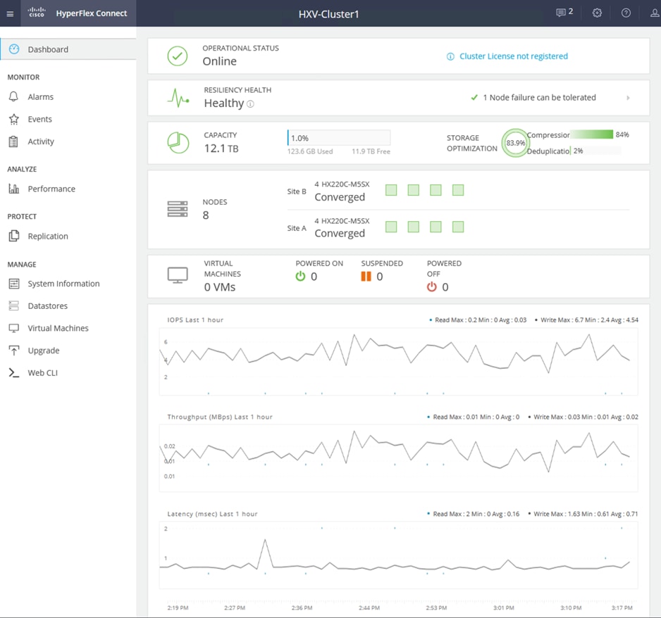
3. The System Information view also provides detailed information on the individual nodes.
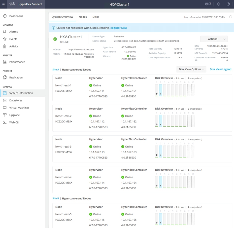
Manage HyperFlex Cluster using Cisco Intersight
Cisco Intersight is a centralized, cloud-based operations and orchestration platform for all Cisco UCS Domains, HyperFlex clusters and servers in an Enterprise regardless of their location. Cisco is SaaS platform that uses CI/CD development model to continuously deliver new features and capabilities to Enterprise. For a complete list of features, please see the Cisco Intersight website.
Cisco Intersight cloud-based management is enabled by a Device Connector running on the device being managed. Device Connector is embedded software that is shipped with Cisco HyperFlex and other Cisco platforms (for example, Cisco UCS FI, Cisco Nexus) to enable the device to initiate communication and register with Cisco Intersight.
Prerequisites
To enable Cisco Intersight cloud-based management of a HyperFlex stretched cluster, the following prerequisites must be met:
● Cisco HyperFlex software version 2.5(1a) or later
● Account on cisco.com
● Account on Cisco Intersight. This can be created by navigating to https://intersight.com and following the instructions for creating an account. The account creation requires at least one device to be registered in Intersight, along with the Device ID and Claim ID from the device.
● Valid Cisco Intersight License
● HyperFlex cluster must have IP reachability to Cisco Intersight from both sites
● HyperFlex cluster must have DNS lookup and resolution capabilities to access Cisco Intersight
● Enterprise must allow outbound HTTPS connections (port 443) initiated from the Device Connector on HyperFlex cluster to Cisco Intersight. If direct access to Internet is not available, the system can connect using a HTTP Proxy server.
To manage the HyperFlex stretched cluster from Cisco Intersight, follow the procedures detailed in the Enable Cisco Intersight Cloud-Based Management section.
Setup Information
The following setup information is required to enable Cisco Intersight cloud-based management of a Cisco HyperFlex cluster. Collect the information as outlined in the Deployment Steps section.
● Device ID
● Claim Code
To enable Cisco Intersight cloud-based management of a Cisco HyperFlex cluster, follow these steps:
1. Use a web browser to navigate to the HyperFlex Connect HTML Management GUI. Log in using the admin account.
2. From the top right corner, click the wheel icon for settings.
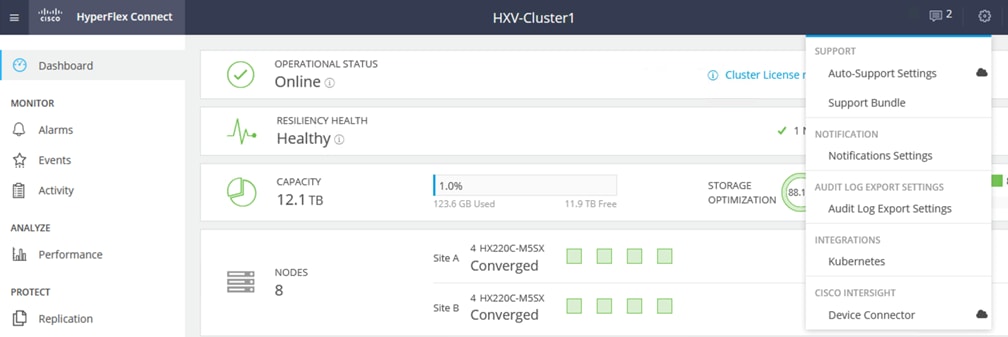
3. Select Cisco Intersight > Device Connector from the menu. From the Device Connector pop-up window, copy the Device ID and Claim ID information. This information will be used in Cisco Intersight.
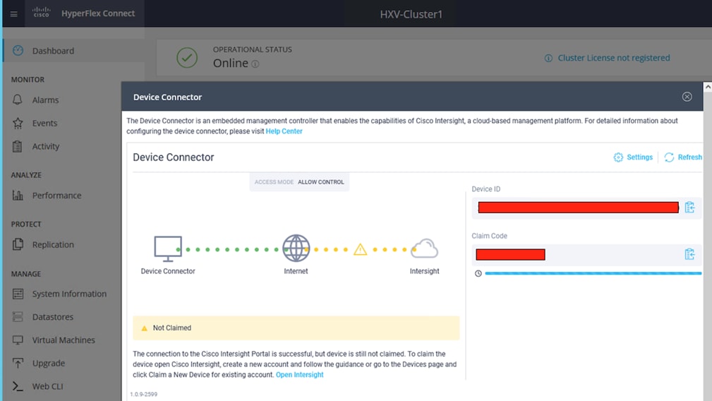
4. Use a web browser to navigate to Cisco Intersight at https://intersight.com/.
5. Log in with a valid cisco.com account or single sign-on using your corporate authentication. Select Account that will be used to manage the HyperFlex cluster.
6. Navigate to ADMIN > Targets in the left navigation menu. Click the Claim Target button in the top right-hand corner.

7. In the Select Target Type window, click on Cisco HyperFlex Cluster to select it.
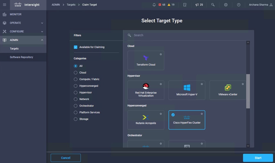
8. Click the Start button. Paste the previously copied Device ID and Claim Code. Click Claim.
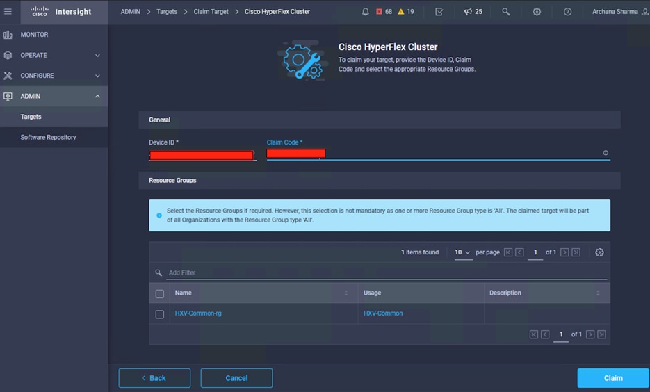
9. On Cisco Intersight, the newly added HyperFlex cluster should now have a Status of Connected.
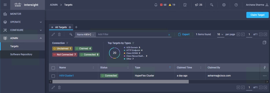
10. On Cisco HyperFlex Connect, the Device Connector should now have a Status of Claimed.
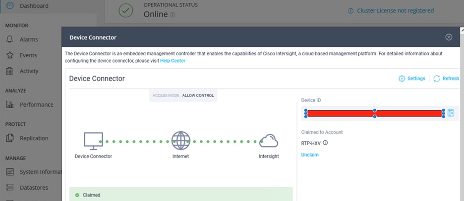
11. Use the left navigation pane to access other Intersight capabilities available for managing and operating a HyperFlex cluster. For example, MONITOR, provides the health and status of the cluster.
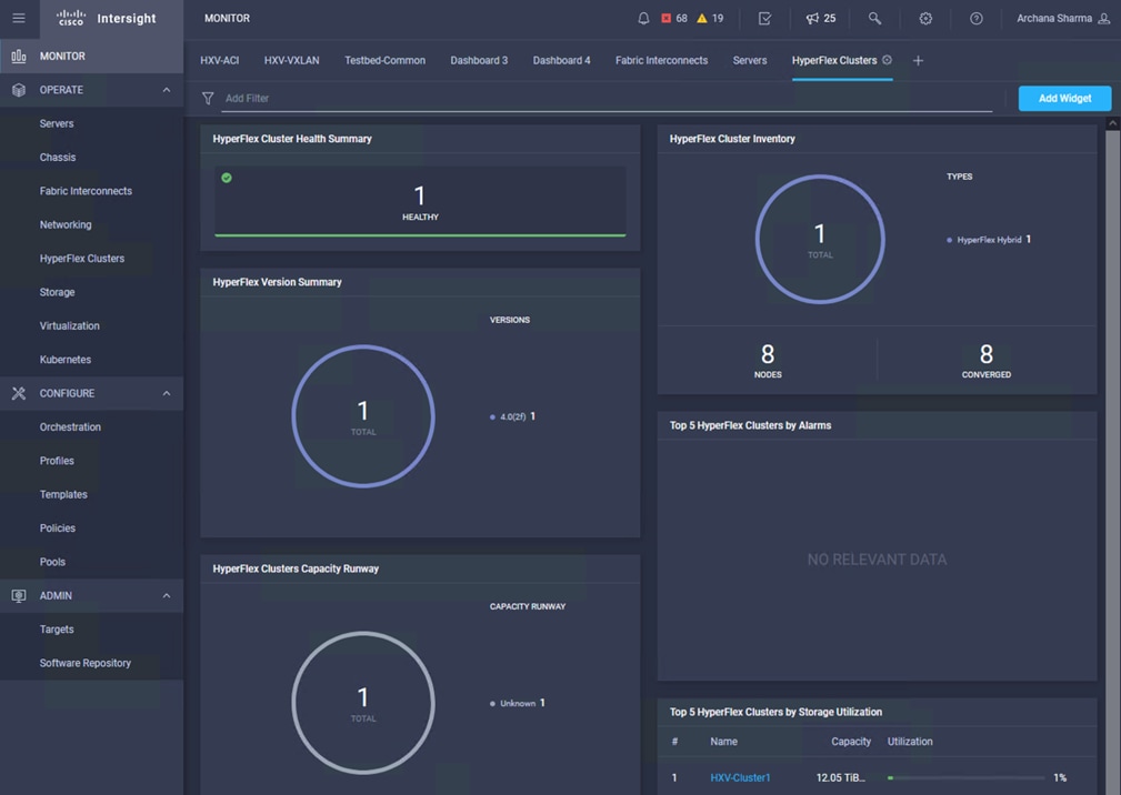
Manage HyperFlex Cluster using HyperFlex HTML5 Plugin for VMWare vCenter
The Cisco HyperFlex plugin for VMware vCenter Web can be deployed as a secondary tool to monitor and configure the HyperFlex cluster. The HyperFlex HTML5 plugin is deployed separately after the cluster is built, and can use the same user management mechanism (RBAC) as HyperFlex Connect. The plugin is available for each HyperFlex release, from the Software Downloads page on cisco.com. The earlier HyperFlex Flash plugin will not be supported in future HyperFlex software releases and VMware has deprecated the vSphere Flash-based Web Client as of vSphere 6.7.
The HyperFlex HTML5 plugin for VMware vCenter can be deployed as outlined in the Cisco HyperFlex Data Platform Administration Guide, Release 4.0 document.
The solution is validated in Cisco Labs with all components integrated to verify the design and ensure interoperability. This section provides a summary of the validation done for this CVD.
Table 20 lists the hardware and software versions used to validate the solution in Cisco labs. The versions are consistent with versions recommended in the interoperability matrixes supported by Cisco and VMware.
Table 20. Solution Components - Hardware and Software
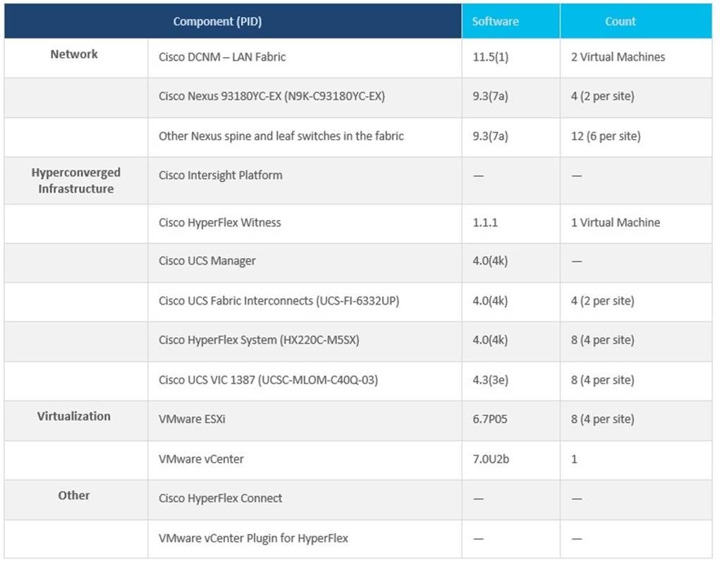
The solution can be deployed using different hardware models or software versions from what was validated in Cisco Labs. When doing so, verify interoperability using the following matrixes. Also, review the release notes for release and product documentation.
● Cisco UCS and HyperFlex Hardware and Software Interoperability Tool
Solution Testing
The solution was built and tested in Cisco Labs to ensure functionality and data forwarding by deploying virtual machine running VdBench and IOMeter tools. The system was validated for resiliency by failing various aspects of the system under load. Examples of the types of tests executed include:
● Failure and recovery of various links and components between the sites and within each site.
● Failure events triggering vSphere high availability between sites.
● Failure events triggering vMotion between sites.
● Site Failures to ensure the second data center site takes over as designed
All tests were performed under load, using load generation tools. Different IO profiles representative of customer deployments were used.
The Cisco HyperFlex Stretched Cluster with Cisco VXLAN EVPN Multi-Site fabric solution delivers an active-active data center design for business continuity and disaster recovery in VMware vSphere environments. The solution protects against a variety of small and large failures, including a complete data center failure. The HyperFlex stretch cluster nodes, running VMware vSphere, are evenly distributed across two geographically separate data center sites to provide the hyperconverged virtual server infrastructure in each data center. The Cisco VXLAN Multi-Site fabric in the design provides Layer 2 extension and Layer 3 connectivity within and across sites to enable the active-active data centers. The HyperFlex stretch cluster synchronously replicates the stored data between sites to ensure quick recovery with zero data loss in the event of a data center site failure.
HyperFlex stretch cluster protects critical business services from site failures with zero RPO and near-zero RTO. HyperFlex Witness and VMware vCenter located in a third site monitor and manage the cluster to ensure the availability of at least one data center site at all times. The Cisco HyperFlex and Cisco UCS infrastructure in two data center sites are centrally managed from the cloud using Cisco Intersight. To simplify and accelerate the infrastructure deployment in the active-active sites, the solution uses GUI-driven automation (Cisco HyperFlex Installer, Cisco DCNM Fabric Builder) for Day-0 provisioning and HashiCorp Terraform for Day 2 provisioning.
The design is validated in Cisco Labs to provide customers and partners with a reliable reference design for deploying their active-active private-cloud solution for business continuity.
This section provides links for additional information on each solution component in this document.
Cisco HyperFlex
● Operating Cisco HyperFlex HX Data Platform Stretch Clusters:
https://www.cisco.com/c/dam/en/us/products/collateral/hyperconverged-infrastructure/hyperflex-hx-series/operating-hyperflex.pdf
● Cisco HyperFlex 4.0 for Virtual Server Infrastructure with VMware ESXi: https://www.cisco.com/c/en/us/td/docs/unified_computing/ucs/UCS_CVDs/hx_4_vsi_vmware_esxi.html
● Cisco HyperFlex Best Practices White Paper:
https://www.cisco.com/c/en/us/products/collateral/hyperconverged-infrastructure/hyperflex-hx-series/white-paper-c11-744135.html
● Cisco HyperFlex:
https://www.cisco.com/c/en/us/products/hyperconverged-infrastructure/index.html?dtid=osscdc000283
● Comprehensive Documentation Roadmap for Cisco HyperFlex: https://www.cisco.com/c/en/us/td/docs/hyperconverged_systems/HyperFlex_HX_DataPlatformSoftware/HX_Documentation_Roadmap/HX_Series_Doc_Roadmap.html
● Converting to VMware vDS from vSwitch in HyperFlex systems: https://www.cisco.com/c/dam/en/us/products/collateral/hyperconverged-infrastructure/hyperflex-hx-series/white-paper-listing.pdf
● Cisco HyperFlex Stretch Cluster Release 4.0 Guide:
https://www.cisco.com/c/en/us/td/docs/hyperconverged_systems/HyperFlex_HX_DataPlatformSoftware/HyperFlex_Stretched_Cluster/4_0/b_HyperFlex_Systems_Stretched_Cluster_Guide_4_0.pdf
● Cisco HyperFlex Data Platform Administration Guide, Release 4.0 https://www.cisco.com/c/en/us/td/docs/hyperconverged_systems/HyperFlex_HX_DataPlatformSoftware/AdminGuide/4_0/b_HyperFlexSystems_AdministrationGuide_4_0.html
● HX220c M5 Server: https://www.cisco.com/c/en/us/td/docs/hyperconverged_systems/HX_series/HX220c_M5/HX220c_M5.html
● Cisco HyperFlex HX Data Platform White Paper:
https://www.cisco.com/c/en/us/products/collateral/hyperconverged-infrastructure/hyperflex-hx-series/white-paper-c11-736814.html
● Cisco Intersight Service for HashiCorp Terraform At-a-Glance:
https://www.cisco.com/c/en/us/products/collateral/cloud-systems-management/intersight/nb-06-intersight-terraf-ser-aag-cte-en.html
● Cisco Intersight Assist Virtual Appliance – Getting Stated Guide: https://www.cisco.com/c/en/us/td/docs/unified_computing/Intersight/cisco-intersight-assist-getting-started-guide/m-installing-cisco-intersight-assist.html
● Cisco Intersight Service for Terraform – Getting Started Guide:
https://cdn.intersight.com/components/an-hulk/1.0.9-750/docs/cloud/data/resources/terraform-service/en/Cisco_IST_Getting_Started_Guide.pdf
Cisco UCS
● Cisco Unified Computing System:
http://www.cisco.com/en/US/products/ps10265/index.html
● Cisco UCS 6300 Series Fabric Interconnects:
http://www.cisco.com/c/en/us/products/servers-unified-computing/ucs-6300-series-fabric-interconnects/index.html
● Cisco UCS Virtual Interface Cards:
https://www.cisco.com/c/en/us/products/interfaces-modules/unified-computing-system-adapters/index.html
Cisco VXLAN and Cisco Nexus Switches
● VXLAN EVPN Multi-Site Design and Deployment White Paper:
https://www.cisco.com/c/en/us/products/collateral/switches/nexus-9000-series-switches/white-paper-c11-739942.html
● IETF Drafts for VXLAN EVPN Multi-Site Fabric:
◦ draft-sharma-multi-site-evpn: https://tools.ietf.org/html/draft-sharma-multi-site-evpn
◦ draft-ietf-bess-evpn-overlay: https://tools.ietf.org/html/draft-ietf-bess-evpn-overlay
◦ BGP MPLS-based Ethernet VPN (RFC-7432): https://tools.ietf.org/html/rfc7432
● VXLAN BGP EVPN–based Multi-Site (BRKDCN-2035):
https://www.ciscolive.com/c/dam/r/ciscolive/emea/docs/2020/pdf/BRKDCN-2035.pdf
● Overlay management and visibility with VXLAN (BRKDCN-2125):
https://www.ciscolive.com/c/dam/r/ciscolive/emea/docs/2020/pdf/BRKDCN-2125.pdf
● Cisco programmable fabric with VXLAN BGP EVPN configuration guide:
https://www.cisco.com/c/en/us/td/docs/switches/datacenter/pf/configuration/guide/b-pf-configuration.html
Archana Sharma, Technical Marketing Engineer, Cisco UCS Solutions, Cisco Systems Inc.
Archana Sharma is a member of Cisco’s Computing Systems Product Group team, with over 20 years of experience on a range of technologies including Data Center, Desktop Virtualization, and Collaboration. Archana’s primary focus is developing data center infrastructure solutions based on Cisco UCS and Cisco HyperFlex. She has 15+ years of solution experience has been delivering Cisco Validated Designs (CVDs) for 10+ years. She does the design, validation, and provides design and deployment guidance for the solutions in CVDs and whitepapers. Archana holds a CCIE (#3080) Emeritus in Routing and Switching and a bachelor’s degree in Electrical Engineering from North Carolina State University.
For comments and suggestions about this guide and related guides, join the discussion on Cisco Community at https://cs.co/en-cvds.