Cisco HyperFlex Edge 4.5 with Cisco ACI and Hashicorp Terraform
Available Languages
Bias-Free Language
The documentation set for this product strives to use bias-free language. For the purposes of this documentation set, bias-free is defined as language that does not imply discrimination based on age, disability, gender, racial identity, ethnic identity, sexual orientation, socioeconomic status, and intersectionality. Exceptions may be present in the documentation due to language that is hardcoded in the user interfaces of the product software, language used based on RFP documentation, or language that is used by a referenced third-party product. Learn more about how Cisco is using Inclusive Language.
- US/Canada 800-553-2447
- Worldwide Support Phone Numbers
- All Tools
 Feedback
 Feedback

Cisco HyperFlex Edge 4.5 with Cisco ACI and Hashicorp Terraform
Deployment Guide for Cisco HyperFlex Edge 4.5 Systems with Cisco ACI Remote Leaf Switches and Terraform Automation
Published: August 2021

About the Cisco Validated Design Program
The Cisco Validated Design (CVD) program consists of systems and solutions designed, tested, and documented to facilitate faster, more reliable, and more predictable customer deployments. For more information, go to:
http://www.cisco.com/go/designzone.
ALL DESIGNS, SPECIFICATIONS, STATEMENTS, INFORMATION, AND RECOMMENDATIONS (COLLECTIVELY, "DESIGNS") IN THIS MANUAL ARE PRESENTED "AS IS," WITH ALL FAULTS. CISCO AND ITS SUPPLIERS DISCLAIM ALL WARRANTIES, INCLUDING, WITHOUT LIMITATION, THE WARRANTY OF MERCHANTABILITY, FITNESS FOR A PARTICULAR PURPOSE AND NONINFRINGEMENT OR ARISING FROM A COURSE OF DEALING, USAGE, OR TRADE PRACTICE. IN NO EVENT SHALL CISCO OR ITS SUPPLIERS BE LIABLE FOR ANY INDIRECT, SPECIAL, CONSEQUENTIAL, OR INCIDENTAL DAMAGES, INCLUDING, WITHOUT LIMITATION, LOST PROFITS OR LOSS OR DAMAGE TO DATA ARISING OUT OF THE USE OR INABILITY TO USE THE DESIGNS, EVEN IF CISCO OR ITS SUPPLIERS HAVE BEEN ADVISED OF THE POSSIBILITY OF SUCH DAMAGES.
THE DESIGNS ARE SUBJECT TO CHANGE WITHOUT NOTICE. USERS ARE SOLELY RESPONSIBLE FOR THEIR APPLICATION OF THE DESIGNS. THE DESIGNS DO NOT CONSTITUTE THE TECHNICAL OR OTHER PROFESSIONAL ADVICE OF CISCO, ITS SUPPLIERS OR PARTNERS. USERS SHOULD CONSULT THEIR OWN TECHNICAL ADVISORS BEFORE IMPLEMENTING THE DESIGNS. RESULTS MAY VARY DEPENDING ON FACTORS NOT TESTED BY CISCO.
CCDE, CCENT, Cisco Eos, Cisco Lumin, Cisco Nexus, Cisco StadiumVision, Cisco TelePresence, Cisco WebEx, the Cisco logo, DCE, and Welcome to the Human Network are trademarks; Changing the Way We Work, Live, Play, and Learn and Cisco Store are service marks; and Access Registrar, Aironet, AsyncOS, Bringing the Meeting To You, Catalyst, CCDA, CCDP, CCIE, CCIP, CCNA, CCNP, CCSP, CCVP, Cisco, the Cisco Certified Internetwork Expert logo, Cisco IOS, Cisco Press, Cisco Systems, Cisco Systems Capital, the Cisco Systems logo, Cisco Unified Computing System (Cisco UCS), Cisco UCS B-Series Blade Servers, Cisco UCS C-Series Rack Servers, Cisco UCS S-Series Storage Servers, Cisco UCS Manager, Cisco UCS Management Software, Cisco Unified Fabric, Cisco Application Centric Infrastructure, Cisco Nexus 9000 Series, Cisco Nexus 7000 Series. Cisco Prime Data Center Network Manager, Cisco NX-OS Software, Cisco MDS Series, Cisco Unity, Collaboration Without Limitation, EtherFast, EtherSwitch, Event Center, Fast Step, Follow Me Browsing, FormShare, GigaDrive, HomeLink, Internet Quotient, IOS, iPhone, iQuick Study, LightStream, Linksys, MediaTone, MeetingPlace, MeetingPlace Chime Sound, MGX, Networkers, Networking Academy, Network Registrar, PCNow, PIX, PowerPanels, ProConnect, ScriptShare, SenderBase, SMARTnet, Spectrum Expert, StackWise, The Fastest Way to Increase Your Internet Quotient, TransPath, WebEx, and the WebEx logo are registered trademarks of Cisco Systems, Inc. and/or its affiliates in the United States and certain other countries. (LDW_P2).
All other trademarks mentioned in this document or website are the property of their respective owners. The use of the word partner does not imply a partnership relationship between Cisco and any other company. (0809R)
© 2021 Cisco Systems, Inc. All rights reserved.
Cisco Intersight Service for Terraform
Installation with Hashicorp Terraform
Post-installation Tasks and Testing
Cisco ACI Remote Leaf Networking
HyperFlex Edge N:1 Replication
Cisco HyperFlex™ Edge systems have established themselves as a premier hyperconverged hardware platform for computing virtualization in small offices and remote locations. Cisco HyperFlex Edge systems are based on Cisco UCS hardware, combining Cisco HX-Series x86 rack-mount servers with industry leading virtualization hypervisor software from VMware, and next-generation software defined storage technology. The combination creates a complete virtualization platform, which provides the network connectivity for the guest virtual machine (VM) connections, and the distributed storage to house the VMs, spread across all of the Cisco UCS x86 servers, versus using specialized storage or networking components. The unique storage features of the HyperFlex log-based filesystem enable rapid cloning of VMs, snapshots without the traditional performance penalties, inline data deduplication and compression, plus VM protection via replication. All configuration, deployment, management, and monitoring of the Cisco HyperFlex Edge solution can be done with standard tools for Cisco UCS and VMware vSphere, such as the cloud-based management platform Cisco Intersight, the integrated HTML management tool HyperFlex Connect, and traditional tools such as VMware vCenter. This powerful linking of advanced technology stacks into a single, simple, rapidly deployed solution makes Cisco HyperFlex a true second generation hyperconverged platform.
Cisco HyperFlex HXDP 4.5 adds to the existing product portfolio by introducing additional features and hardware options which enhance the flexibility and performance of the HyperFlex cluster. New drive models and capacities are offered up to 7.6 TB per disk, and support for VMware ESXi 7.0 is introduced. System security and reliability is enhanced by offering the capability to configure the servers with two boot drives operating in a redundant RAID 1 configuration, and also enabling UEFI secure boot mode to ensure no unsigned or rogue code is executed during system startup. Security is further improved by removing root user access to the HyperFlex controller VMs and replacing it with a reduced rights secure admin login and console shell. Cisco HyperFlex Edge is now available on full-depth HX-240 model servers for deployments which require larger storage capacities than is available from the smaller HX-220 model servers. Edge clusters can also benefit from using replication factor 3 to ensure the highest level of data protection. A new local witness feature allows certain PDU management modules to perform the witness functions for 2-node Edge clusters, versus relying on the invisible cloud witness service. Native data protection features are enhanced with the capability to schedule routine snapshots from the HyperFlex connect management page, and N:1 replication of VMs from multiple HyperFlex Edge clusters to a single target managed via Cisco Intersight.
Cisco’s partnership with Hashicorp has enabled new levels of integration with Terraform, which can be used either in an on-premise configuration, or via the cloud using Terraform Cloud for Business. While Terraform plans can easily be executed against our cloud-based Cisco Intersight management platform, not all Cisco products can be managed via Cisco Intersight today. For these products, normally a Terraform plan would need to be executed from within the network. A new feature in Cisco Intersight named Intersight Service for Terraform allows agents within your environment to run Terraform plans which are managed and triggered via Terraform Cloud. This combination allows Hashicorp Terraform to be used for deployments of Cisco HyperFlex Edge systems via Cisco Intersight, and also to configure your Cisco ACI fabric using the new Intersight Service for Terraform.
The Cisco HyperFlex System provides an all-purpose virtualized server platform, with hypervisor hosts, networking connectivity, and virtual server storage across a set of Cisco UCS HX-Series x86 rack-mount servers. Datacenter architectures have evolved away from the traditional legacy platforms, which typically contained a disparate set of technologies, such as individual servers for applications or hosting virtual machines (VMs), network switches connecting endpoints and transferring Ethernet network traffic, and Fibre Channel (FC) storage arrays providing block-based storage via a dedicated storage area network (SAN). The rapid increase in processing power and storage resources available in modern servers has led to the rise of Software-Defined Storage (SDS), where distributed software replaces the functions of traditional storage controllers. Using a distributed SDS platform, a group of rack-mount servers can effectively be turned into a clustered storage system. If the servers that provided the SDS environment were in fact the same model of server that typically hosts guest VMs, could they simply do both things at once and collapse the two functions into one? This ultimate combination of resources becomes what the industry has given the moniker of a hyperconverged infrastructure. Hyperconverged infrastructures coalesce the computing, memory, hypervisor, and storage devices of servers into a single platform for virtual servers. There is no longer a separate storage system, as the servers running the hypervisors to host virtual machines, also provide the software defined storage resources to store the virtual servers, ultimately storing the virtual machines on themselves.
The Cisco HyperFlex system is a next-generation hyperconverged platform, which uniquely combines the convergence of computing and networking provided by Cisco UCS, along with advanced custom hyperconverged storage software, to provide the compute resources, network connectivity, distributed storage, and hypervisor platform to run an entire virtualized environment, all contained in a single uniform system. Some key advantages of hyperconverged infrastructures are the simplification of deployment and day to day management operations, as well as increased agility, thereby reducing the amount of ongoing operational costs. Since hyperconverged storage can be easily managed by an IT generalist, this can also reduce technical debt that is accrued from implementing complex systems, which often need dedicated management teams and skillsets. Cisco HyperFlex is available in three core configurations; a single site cluster managed by Cisco UCS Fabric Interconnects, a split two-site cluster managed by two pairs of Cisco UCS Fabric Interconnects, and a smaller scale single site deployment without the use of Fabric Interconnects, called HyperFlex Edge, which is the subject of this paper.
Cisco HyperFlex Edge systems are designed as a smaller scale and lower cost compute platform for remote offices and branch offices (also referred to as ROBO), or any other kind of smaller sized or geographically dispersed locations. For example, while traditional branch offices, sales offices or retail sales locations are an easy fit, Cisco HyperFlex Edge can be used in many other environments, such as a remote mining site, drilling platforms, research stations, even cargo container ships. Cisco HyperFlex Edge offers the maximum flexibility of deployment options, from clusters as small as 2 nodes, up to a maximum of 4 nodes. Network options are available for 1Gb, 10Gb and 25Gb Ethernet connection speeds to standard Ethernet switches, using a single network switch or a pair of redundant switches. In additional to traditional network switching and WAN technologies, HyperFlex Edge can be deployed to multiple locations across your WAN and LAN running a Cisco Application Centric Infrastructure (ACI) fabric. Cisco ACI version 3.1 introduced the concept of an ACI Remote Leaf switch running on its own, outside of a traditional ACI pod, which is a natural alignment with the typical deployment model of a Cisco HyperFlex Edge cluster.
Cisco HyperFlex Edge systems are deployed and managed via Cisco Intersight, the cloud-based management platform for Cisco UCS. A Hashicorp Terraform provider for Cisco Intersight is available to automate the configuration of resources within Cisco Intersight, hence the installation of Cisco HyperFlex Edge can be executed by running Terraform plans. For Cisco products such as ACI, and others which are not currently managed directly by Cisco Intersight, a new feature in Cisco Intersight named Intersight Service for Terraform (IST) allows agents within your environment to run Terraform plans which are managed and triggered via Terraform Cloud for Business. In combination, these tools allow for deployment of Cisco HyperFlex Edge and ACI Remote Leaf networking in an Infrastructure-as-Code (IaC) model, where the configuration steps can all be executed using Terraform from a local workstation, or via Terraform Cloud for Business, versus the manual configuration methods using Cisco Intersight and the Cisco Application Policy Infrastructure Controller (APIC) for ACI.
The intended audience for this document includes, but is not limited to, sales engineers, field consultants, professional services, IT managers, partner engineering, and customers deploying the Cisco HyperFlex System. External references are provided wherever applicable, but readers are expected to be familiar with VMware specific technologies, Cisco ACI, infrastructure concepts, networking connectivity, and security policies of the customer installation.
This document describes the steps required to deploy, configure, and manage Cisco HyperFlex Edge systems using the VMware ESXi hypervisor via the Cisco Intersight cloud-based management portal. The document is based on all known best practices using the software, hardware and firmware revisions specified in the document at the time of publication. As such, recommendations and best practices can be amended with later versions. This document showcases the installation and configuration of Cisco HyperFlex Edge using Cisco Intersight, both manually and via the Cisco Intersight Terraform provider. In addition, configuration of Cisco ACI Remote Leaf switches to support the Cisco HyperFlex Edge deployment is presented, both using Cisco APIC and using Terraform. Example Terraform plans are provided as reference along with instructions for their use. While readers of this document are expected to have sufficient knowledge to install and configure the products used, configuration details that are important to the deployment of this solution are provided in this CVD.
The Cisco HyperFlex Edge system has several new capabilities and enhancements in version 4.5:
● HyperFlex Edge 240 Full Depth Servers: New, full depth server offerings are now available for HyperFlex Edge. For more details, see the HyperFlex HX240 M5 Edge Hybrid and All Flash spec sheet.
● RAID Support for Boot Drives: Support for Hardware RAID M.2 boot drives in HyperFlex converged and compute-only nodes. Requires optional HX-M2-HWRAID controller with two boot drives. Existing single boot drive option remains supported.
● UEFI Secure Boot Mode: HX 4.5 simplifies the hardening of hypervisor (ESXi) boot security by providing an automated workflow that non-disruptively changes the boot mode of converged and compute nodes in the cluster to Unified Extensible Firmware Interface (UEFI) Secure Boot, in which the chain of trust is anchored by a hardware trust anchor (such as the Cisco Trust Anchor module) built-in to UCS rack and blade servers.
● vCenter Re-Registration: a new user-interface based feature that allows you to move a HyperFlex cluster to a new vCenter.
● HyperCheck 4.5: An enhanced HyperCheck script is now included with the product and Rest APIs integration with improved performance. You can perform HyperCheck at any time, and it is recommended that you perform HyperCheck prior to upgrades. New features and checks include Cluster Information table, DR (local and remote network) and SED checks for users who have them enabled.
● Scheduled Snapshots in HX Connect: Provides users the ability to manage and monitor Snapshots and Schedule Snapshots from the HX Connect Web UI.
● RF3 support for HX Edge: New HyperFlex Edge deployments can be configured with RF3 for higher resiliency and availability. RF3 is the default setting for 3 node Edge clusters and larger, which follows Cisco's best practices for production clusters.
● HX Drive Catalog: This new capability simplifies the introduction of new drives by allowing customers to perform an HX drive catalog-only upgrade to start consuming new drives and models introduced in the future, without requiring a full HyperFlex Data Platform upgrade.
● Secure Admin Shell: HX 4.5 introduces a new command-line shell, the Admin Shell, which restricts commands executable by an authenticated "admin" user login to a set of allow-listed administrative commands. Command-line login to the Controller VM as the "root" user is also removed. The Admin Shell improves the built-in security posture of the Controller VM by reducing its attack surface.
● N:1 Replication for HyperFlex Edge Clusters: Provides the ability for HyperFlex Edge clusters to take snapshots of Virtual Machines and restore using Intersight. Users can configure multiple HyperFlex Edge clusters at different sites with backup policies to create snapshots of virtual machine data which is replicated to a centralized HyperFlex backup target cluster.
● Local External Witness: Introducing new external local hardware witness support for HyperFlex Edge 2-Node Clusters. This feature increases cluster availability and flexibility for remote sites which will not use the Cisco Intersight invisible cloud-based witness service.
For the comprehensive documentation suite, refer to the following for the Cisco UCS HX-Series Documentation Roadmap: https://www.cisco.com/c/en/us/td/docs/hyperconverged_systems/HyperFlex_HX_DataPlatformSoftware/HX_Documentation_Roadmap/HX_Series_Doc_Roadmap.html
![]() A login is required for the Documentation Roadmap.
A login is required for the Documentation Roadmap.
The Cisco HyperFlex system provides a fully contained virtual server platform, with compute and memory resources, integrated networking connectivity, a distributed high-performance log-based filesystem for VM storage, and the hypervisor software for running the virtualized servers, all within a cluster of Cisco UCS rack-mount servers.
Figure 1. HyperFlex Edge System Overview
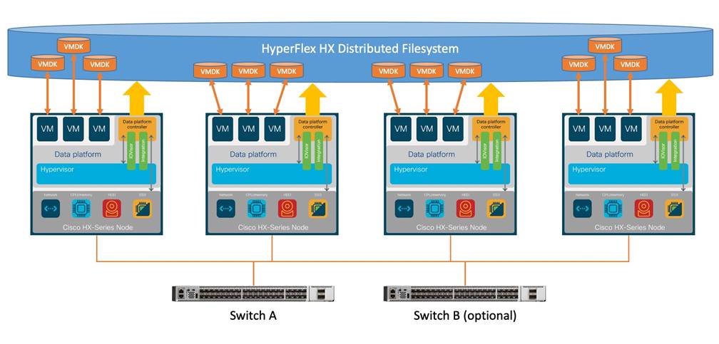
The following are the components of a Cisco HyperFlex Edge system using the VMware ESXi Hypervisor:
● Two to Four Cisco HyperFlex HX-Series Rack-Mount Servers, choose from models:
◦ Cisco HyperFlex HX-E-220M5SX Rack-Mount Servers
◦ Cisco HyperFlex HX-E-240-M5SX Rack-Mount Servers
◦ Cisco HyperFlex HXAF-E-220M5SX All-Flash Rack-Mount Servers
◦ Cisco HyperFlex HXAF-E-240-M5SX All-Flash Rack-Mount Servers
◦ Cisco HyperFlex HX240C-M5SD Short-Depth Rack-Mount Servers
◦ Cisco HyperFlex HXAF240C-M5SD All-Flash Short-Depth Rack-Mount Servers
● Cisco HyperFlex Data Platform Software
● VMware vSphere ESXi Hypervisor
● VMware vCenter Server (end-user supplied)
Cisco HyperFlex Data Platform Software
The Cisco HyperFlex HX Data Platform is a purpose-built, high-performance, distributed file system with a wide array of enterprise-class data management services. The data platform’s innovations redefine distributed storage technology, exceeding the boundaries of first-generation hyperconverged infrastructures. The data platform has all the features expected in an enterprise shared storage system, eliminating the need to configure and maintain complex Fibre Channel storage networks and devices. The platform simplifies operations and helps ensure data availability. Enterprise-class storage features include the following:
● Data protection creates multiple copies of the data across the cluster so that data availability is not affected if single or multiple components fail (depending on the replication factor configured).
● Deduplication is always on, helping reduce storage requirements in virtualization clusters in which multiple operating system instances in guest virtual machines result in large amounts of replicated data.
● Compression further reduces storage requirements, reducing costs, and the log-structured file system is designed to store variable-sized blocks, reducing internal fragmentation.
● Replication copies virtual machine level snapshots from one Cisco HyperFlex cluster to another, to facilitate recovery from a cluster or site failure, via a failover to the secondary site of all VMs.
● Thin provisioning allows large volumes to be created without requiring storage to support them until the need arises, simplifying data volume growth and making storage a "pay as you grow" proposition.
● Fast, space-efficient clones rapidly duplicate virtual storage volumes so that virtual machines can be cloned simply through metadata operations, with actual data copied only for write operations.
● Snapshots help facilitate backup and remote-replication operations, which are needed in enterprises that require always-on data availability.
Cisco HyperFlex HX Data Platform Controller
A Cisco HyperFlex HX Data Platform controller resides on each node and implements the distributed file system. The controller runs as software in user space within a virtual machine, and intercepts and handles all I/O from the guest virtual machines. The Storage Controller Virtual Machine (SCVM) uses the VMDirectPath I/O feature to provide direct PCI passthrough control of the physical server’s SAS disk controller, or direct control of the PCI attached NVMe based SSDs. This method gives the controller VM full control of the physical disk resources, utilizing the SSD drives as a read/write caching layer, and the HDDs or SDDs as a capacity layer for distributed storage. The controller integrates the data platform into the VMware vSphere cluster through the use of three preinstalled VMware ESXi vSphere Installation Bundles (VIBs) on each node:
● scvmclient: This VIB, also called the HyperFlex IO Visor, provides a network file system (NFS) mount point so that the ESXi hypervisor can access the virtual disks that are attached to individual virtual machines. From the hypervisor’s perspective, it is simply attached to a network file system. The IO Visor intercepts guest VM IO traffic, and intelligently redirects it to the HyperFlex SCVMs.
● STFSNasPlugin: This VMware API for Array Integration (VAAI) storage offload API allows vSphere to request advanced file system operations such as snapshots and cloning. The controller implements these operations via manipulation of the filesystem metadata rather than actual data copying, providing rapid response, and thus rapid deployment of new environments.
● stHypervisorSvc: This VIB adds enhancements and features needed for HyperFlex data protection and VM replication.
Data Operations and Distribution
The Cisco HyperFlex HX Data Platform controllers handle all read and write operation requests from the guest VMs to their virtual disks (VMDK) stored in the distributed datastores in the cluster. The data platform distributes the data across multiple nodes of the cluster, and also across multiple capacity disks of each node, according to the replication level policy selected during the cluster setup. This method avoids storage hotspots on specific nodes, and on specific disks of the nodes, and thereby also avoids networking hotspots or congestion from accessing more data on some nodes versus others.
The policy for the number of duplicate copies of each storage block is chosen during cluster setup and is referred to as the replication factor (RF).
● Replication Factor 3: For every I/O write committed to the storage layer, 2 additional copies of the blocks written will be created and stored in separate locations, for a total of 3 copies of the blocks. Blocks are distributed in such a way as to ensure multiple copies of the blocks are not stored on the same disks, nor on the same nodes of the cluster. This setting can tolerate simultaneous failures of 2 entire nodes in a cluster of 5 nodes or greater, without losing data and resorting to restore from backup or other recovery processes. RF3 is recommended for all production systems and is the default for all clusters of 3 nodes or more.
● Replication Factor 2: For every I/O write committed to the storage layer, 1 additional copy of the blocks written will be created and stored in separate locations, for a total of 2 copies of the blocks. Blocks are distributed in such a way as to ensure multiple copies of the blocks are not stored on the same disks, nor on the same nodes of the cluster. This setting can tolerate a failure of 1 entire node without losing data and resorting to restore from backup or other recovery processes. RF2 is suitable for non-production systems, or environments where the extra data protection is not needed. RF2 is the only setting available for two node clusters.
Data Write and Compression Operations
Internally, the contents of each guest VM's virtual disks are subdivided and spread across multiple servers by the HXDP software. For each write operation, the data is intercepted by the IO Visor module on the node where the VM is running, a primary node is determined for that particular operation via a hashing algorithm, and then sent to the primary node via the network. The primary node compresses the data in real time, writes the compressed data to the write log on its caching SSD, and replica copies of that compressed data are sent via the network and written to the write log on the caching SSD of the remote nodes in the cluster, according to the replication factor setting. For example, at RF=3 a write operation will be written to write log of the primary node for that virtual disk address, and two additional writes will be committed in parallel on two other nodes. Because the virtual disk contents have been divided and spread out via the hashing algorithm for each unique operation, this method results in all writes being spread across all nodes, avoiding the problems with data locality and "noisy" VMs consuming all the IO capacity of a single node. The write operation will not be acknowledged until all three copies are written to the caching layer SSDs. Written data is also cached in a write log area resident in memory in the controller VM, along with the write log on the caching SSDs. This process speeds up read requests when reads are requested of data that has recently been written.
Data Destaging and Deduplication
The Cisco HyperFlex HX Data Platform constructs multiple write log caching segments on the caching SSDs of each node in the distributed cluster. As write cache segments become full and based on policies accounting for I/O load and access patterns, those write cache segments are locked and new writes roll over to a new write cache segment. The data in the now locked cache segment is destaged to the HDD capacity layer of the nodes for the Hybrid system or to the SSD capacity layer of the nodes for the All-Flash systems. During the destaging process, data is deduplicated before being written to the capacity storage layer, and the resulting data can now be written to the HDDs or SDDs of the server. On hybrid systems, the now deduplicated and compressed data is also written to the dedicated read cache area of the caching SSD, which speeds up read requests of data that has recently been written. When the data is destaged to the capacity disks, it is written in a single sequential operation, avoiding disk head seek thrashing on the spinning disks and accomplishing the task in the minimal amount of time. Since the data is already deduplicated and compressed before being written, the platform avoids additional I/O overhead often seen on competing systems, which must later do a read/dedupe/compress/write cycle. Deduplication, compression and destaging take place with no delays or I/O penalties to the guest VMs making requests to read or write data, which benefits both the HDD and SDD configurations.
Figure 2. HyperFlex HX Data Platform Data Movement
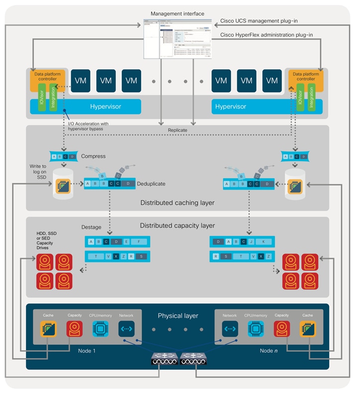
For data read operations, data may be read from multiple locations. For data that was very recently written, the data is likely to still exist in the write log of the local platform controller memory, or the write log of the local caching layer disk. If local write logs do not contain the data, the distributed filesystem metadata will be queried to see if the data is cached elsewhere, either in write logs of remote nodes, or in the dedicated read cache area of the local and remote caching SSDs of hybrid nodes. Finally, if the data has not been accessed in a significant amount of time, the filesystem will retrieve the requested data from the distributed capacity layer. As requests for reads are made to the distributed filesystem and the data is retrieved from the capacity layer, the caching SSDs of hybrid nodes populate their dedicated read cache area to speed up subsequent requests for the same data. This multi-tiered distributed system with several layers of caching techniques, ensures that data is served at the highest possible speed, leveraging the caching SSDs of the nodes fully and equally. All-flash configurations do not employ a dedicated read cache, because such caching does not provide any performance benefit since the persistent data copy already resides on high-performance SSDs.
In summary, the Cisco HyperFlex HX Data Platform implements a distributed, log-structured file system that performs data operations via two configurations:
● In a Hybrid configuration, the data platform provides a caching layer using SSDs to accelerate read requests and write responses, and it implements a storage capacity layer using HDDs.
● In an All-Flash configuration, the data platform provides a dedicated caching layer using high endurance SSDs to accelerate write responses, and it implements a storage capacity layer also using SSDs. Read requests are fulfilled directly from the capacity SSDs, as a dedicated read cache is not needed to accelerate read operations.
The Cisco HyperFlex product family can be divided logically into two families; a collection of hybrid nodes, and a collection of all-flash nodes. Hybrid converged nodes use a combination of solid-state disks (SSDs) for the short-term storage caching layer, and hard disk drives (HDDs) for the long-term storage capacity layer. The hybrid HyperFlex system is an excellent choice for entry-level or midrange storage solutions, and hybrid solutions have been successfully deployed in many non-performance sensitive virtual environments. Meanwhile, there is significant growth in deployment of highly performance sensitive and mission critical applications. The primary challenge to the hybrid HyperFlex system from these highly performance sensitive applications, is their increased sensitivity to high storage latency. Due to the characteristics of the spinning hard disks, it is unavoidable that their higher latency becomes the bottleneck in the hybrid system. Ideally, if all of the storage operations were to occur in the caching SSD layer, the hybrid system’s performance will be excellent. But in several scenarios, the amount of data being written and read exceeds the caching layer capacity, placing larger loads on the HDD capacity layer, and the subsequent increases in latency will naturally result in reduced performance.
Cisco All-Flash HyperFlex systems are an excellent option for customers with a requirement to support high performance, latency sensitive workloads. Because the capacity layer disks are also SSDs, the all-flash systems avoid the increased latency seen in hybrid nodes when larger amounts of data are written and read. With a purpose built, flash-optimized and high-performance log-based filesystem, the Cisco All-Flash HyperFlex system provides:
● Predictable high performance across all the virtual machines the cluster.
● Highly consistent and low latency, which benefits data-intensive applications.
● Future ready architecture that is well suited for flash-memory configuration:
◦ Cluster-wide SSD pooling maximizes performance and balances SSD usage so as to spread the wear.
◦ A fully distributed log-structured filesystem optimizes the data path to help reduce write amplification.
◦ Large sequential writing reduces flash wear and increases component longevity.
◦ Inline space optimization, for example deduplication and compression, minimizes data operations and reduces wear.
● Lower operating cost with the higher density drives for increased capacity of the system.
● Cloud scale solution with easy scale-out and distributed infrastructure and the flexibility of scaling out independent resources separately.
Cisco HyperFlex support for hybrid and all-flash models allows customers to choose the right platform configuration based on their capacity, applications, performance, and budget requirements. All-flash configurations offer repeatable and sustainable high performance, especially for scenarios with a larger working set of data, in other words, a large amount of data in motion. Hybrid configurations are a good option for customers who want the simplicity of the Cisco HyperFlex solution, but their needs focus on capacity-sensitive solutions, lower budgets, and fewer performance-sensitive applications.
Cisco Intersight Cloud Based Management
Cisco Intersight (https://intersight.com) is the latest visionary cloud-based management tool, designed to provide a centralized off-site management, monitoring, and reporting tool for all of your Cisco UCS based solutions, and can be used to deploy and manage Cisco HyperFlex clusters. Cisco Intersight offers direct links to Cisco UCS Manager and Cisco HyperFlex Connect for systems it is managing and monitoring. The Cisco Intersight website and framework is being constantly upgraded and extended with new and enhanced features independently of the products that are managed, meaning that many new features and capabilities can come with no downtime or upgrades required by the end users. This unique combination of embedded and online technologies results in a complete cloud-based management solution that can care for Cisco HyperFlex throughout the entire lifecycle, from deployment through retirement.
Figure 3. Cisco Intersight

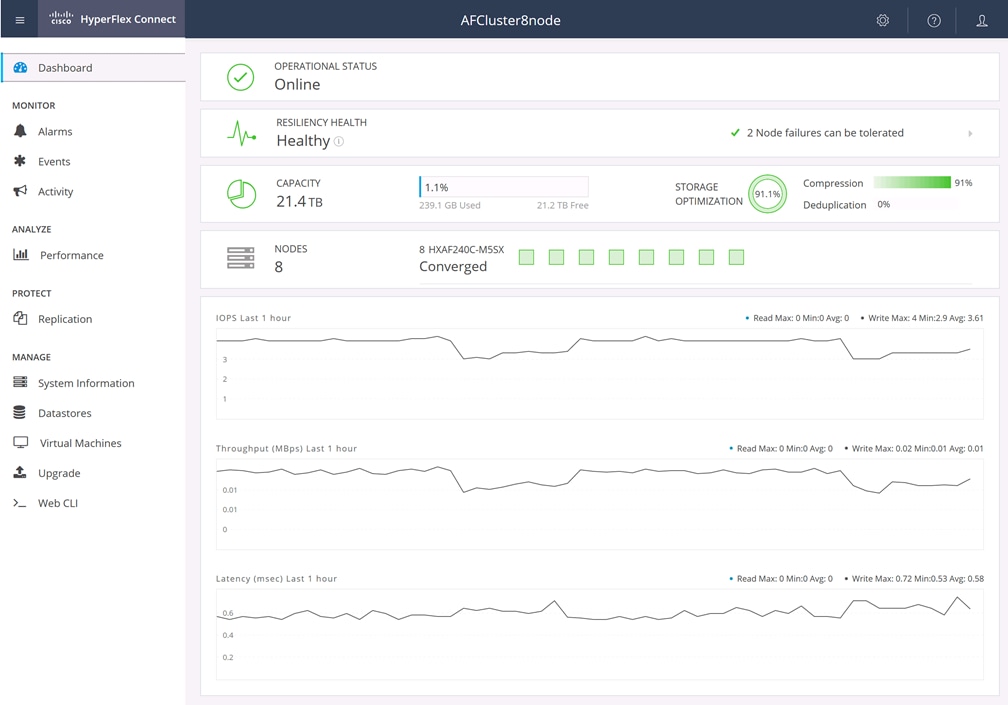
Cisco HyperFlex Connect HTML5 Management Web Page
An HTML 5 based Web UI named HyperFlex Connect is available for use as the primary management tool for Cisco HyperFlex. Through this centralized point of control for the cluster, administrators can create datastores, monitor the data platform health and performance, manage resource usage, and perform upgrades. Administrators can also use this management portal to predict when the cluster will need to be scaled, create VM snapshot schedules and configure native VM replication. To use the HyperFlex Connect UI, connect using a web browser to the HyperFlex cluster IP address: http://<hx controller cluster ip>.
Figure 4. HyperFlex Connect GUI
A HyperFlex Edge cluster requires a minimum of two HX-Series nodes. Each node is equipped with at least one high-performance SSD drive for data caching and rapid acknowledgment of write requests. Each node also is equipped with additional disks, up to the platform’s physical limit, for long term storage and capacity.
Cisco HyperFlex HXAF-E-220M5SX All-Flash Node
This small footprint (1RU) Cisco HyperFlex Edge all-flash model contains one or two 240 GB M.2 form factor solid-state disks (SSD) that acts as the boot drive. When two boot drives are ordered the optional HX-M2-HWRAID controller must be included to enable RAID 1 boot drive redundancy. A 240 GB housekeeping SSD drive, an 800 GB SAS SSD or 1.6 TB SAS SSD write-log drive, and three to eight 960 GB, 3.8 TB or 7.6 TB SATA SSD drives are included for storage capacity. A Cisco VIC model 1457 quad-port 10/25 Gb is included for 10/25GbE configurations, or an Intel i350 quad-port PCIe NIC plus the onboard 1GbE LoM ports are used for 1GbE connectivity.
Figure 5. HXAF-E-220M5SX All-Flash Node
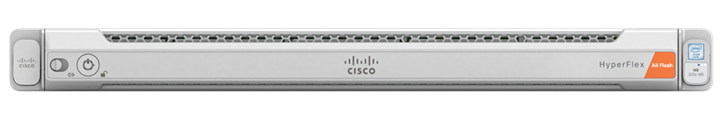
Table 1 lists the hardware component options for the HXAF-E-220M5SX server model.
Table 1. HXAF-E-220M5SX Server Options
| HXAF220c-M5SX Options |
Hardware Required |
| Processors |
Choose one or two 2nd Generation Intel Xeon Processor Scalable Family CPUs |
| Memory |
192 GB to 3 TB of total memory using 16 GB, 32 GB, 64 GB, or 128 GB DDR4 2666 MHz or 2933 MHz 1.2v modules depending on CPU type |
| Disk Controller |
Cisco 12Gbps Modular SAS HBA |
| SSDs |
One 240 GB 2.5 Inch Enterprise Value 6G SATA SSD One 800 GB 2.5 Inch Enterprise Performance SAS SSD, or one 1.6 TB 2.5 Inch Enterprise Performance SAS SSD Three to eight 960 GB, 3.8 TB, or 7.6 TB 2.5 Inch Enterprise Value SAS or SATA SSDs |
| Network |
Cisco UCS VIC1457 VIC MLOM card or Intel i350 quad-port PCIe NIC |
| Boot Device |
One or two 240 GB M.2 form factor SATA SSDs |
| microSD Card |
One 32GB microSD card for local host utilities storage |
| Optional |
M.2 RAID controller |
Cisco HyperFlex HXAF-E-240-M5SX All-Flash Node
This capacity optimized (2RU) Cisco HyperFlex all-flash model contains one or two 240 GB M.2 form factor solid-state disks (SSD) that acts as the boot drive. When two boot drives are ordered the optional HX-M2-HWRAID controller must be included to enable RAID 1 boot drive redundancy. A 240 GB housekeeping SSD drive, an 800 GB SAS SSD or 1.6 TB SAS SSD write-log drive, and three to twenty-three 960 GB, 3.8 TB or 7.6 TB SATA SSD drives are included for storage capacity. A Cisco VIC model 1457 quad-port 10/25 Gb is included for 10/25GbE configurations, or an Intel i350 quad-port PCIe NIC plus the onboard 1GbE LoM ports are used for 1GbE connectivity.
Figure 6. HXAF-E-240-M5SX Node
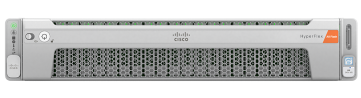
Table 2 lists the hardware component options for the HXAF-E-240-M5SX server model.
Table 2. HXAF-E-240-M5SX Server Options
| HXAF240c-M5SX Options |
Hardware Required |
| Processors |
Choose one or two 2nd Generation Intel Xeon Processor Scalable Family CPUs |
| Memory |
192 GB to 3 TB of total memory using 16 GB, 32 GB, 64 GB, or 128 GB DDR4 2666 MHz or 2933 MHz 1.2v modules depending on CPU type |
| Disk Controller |
Cisco 12Gbps Modular SAS HBA |
| SSD |
One 240 GB 2.5 Inch Enterprise Value 6G SATA SSD One 800 GB 2.5 Inch Enterprise Performance SAS SSD, or one 1.6 TB 2.5 Inch Enterprise Performance SAS SSD Three to twenty-three 960 GB, 3.8 TB, or 7.6 TB 2.5 Inch Enterprise Value SAS or SATA SSDs |
| Network |
Cisco UCS VIC1457 VIC MLOM card or Intel i350 quad-port PCIe NIC |
| Boot Device |
One or two 240 GB M.2 form factor SATA SSDs |
| microSD Card |
One 32GB microSD card for local host utilities storage |
| Optional |
M.2 RAID controller |
Cisco HyperFlex HX-E-220M5SX Hybrid Node
This small footprint (1RU) Cisco HyperFlex Edge hybrid model contains one or two 240 GB M.2 form factor solid-state disks (SSD) that acts as the boot drive. When two boot drives are ordered the optional HX-M2-HWRAID controller must be included to enable RAID 1 boot drive redundancy. A 240 GB housekeeping SSD drive, either a single 480 GB SATA SSD or 800 GB SAS SSD write-log drive, and three to eight 1.2 TB, 1.8 TB or 2.4 TB 10K RPM SAS HDD drives are included for storage capacity. A Cisco VIC model 1457 quad-port 10/25 Gb is included for 10/25GbE configurations, or an Intel i350 quad-port PCIe NIC plus the onboard 1GbE LoM ports are used for 1GbE connectivity.
Figure 7. HX-E-220M5SX Node
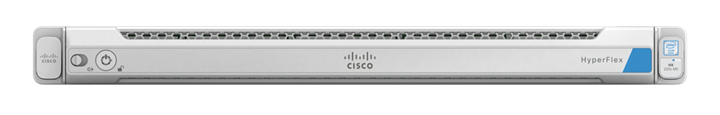
Table 3 lists the hardware component options for the HX-E-220M5SX server model.
Table 3. HX-E-220M5SX Server Options
| HX220c-M5SX Options |
Hardware Required |
| Processors |
Choose one or two 2nd Generation Intel Xeon Processor Scalable Family CPUs |
| Memory |
192 GB to 3 TB of total memory using 16 GB, 32 GB, 64 GB, or 128 GB DDR4 2666 MHz or 2933 MHz 1.2v modules depending on CPU type |
| Disk Controller |
Cisco 12Gbps Modular SAS HBA |
| SSDs |
One 240 GB 2.5 Inch Enterprise Value 6G SATA SSD One 480 GB 2.5 Inch Enterprise Performance 6G SATA SSD, or one 800 GB 2.5 Inch Enterprise Performance 12G SAS SSD |
| HDDs |
Three to eight 1.2 TB, 1.8 TB or 2.4 TB SAS 12G 10K RPM SFF HDDs |
| Network |
Cisco UCS VIC1457 VIC MLOM card or Intel i350 quad-port PCIe NIC |
| Boot Device |
One or two 240 GB M.2 form factor SATA SSDs |
| microSD Card |
One 32GB microSD card for local host utilities storage |
| Optional |
M.2 RAID controller |
Cisco HyperFlex HX-E-240-M5SX Hybrid Node
This capacity optimized (2RU) Cisco HyperFlex hybrid model contains one or two 240 GB M.2 form factor solid-state disks (SSD) that acts as the boot drive. When two boot drives are ordered the optional HX-M2-HWRAID controller must be included to enable RAID 1 boot drive redundancy. A 240 GB housekeeping SSD drive, a single 1.6 TB SAS SSD write-log drive, and three to twenty-three 1.2 TB, 1.8 TB or 2.4 TB 10K RPM SAS HDD drives are included for storage capacity. A Cisco VIC model 1457 quad-port 10/25 Gb is included for 10/25GbE configurations, or an Intel i350 quad-port PCIe NIC plus the onboard 1GbE LoM ports are used for 1GbE connectivity.
Figure 8. HX-E-240-M5SX Node
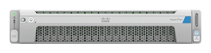
Table 4 lists the hardware component options for the HX-E-240-M5SX server model.
Table 4. HX-E-240-M5SX Server Options
| HX240c-M5SX Options |
Hardware Required |
| Processors |
Choose one or two 2nd Generation Intel Xeon Processor Scalable Family CPUs |
| Memory |
192 GB to 3 TB of total memory using 16 GB, 32 GB, 64 GB, or 128 GB DDR4 2666 MHz or 2933 MHz 1.2v modules depending on CPU type |
| Disk Controller |
Cisco 12Gbps Modular SAS HBA |
| SSDs |
One 240 GB 2.5 Inch Enterprise Value 6G SATA SSD One 1.6 TB 2.5 Inch Enterprise Performance 12G SAS SSD |
| HDDs |
Three to twenty-three 1.2 TB, 1.8 TB or 2.4 TB SAS 12G 10K RPM SFF HDD |
| Network |
Cisco UCS VIC1457 VIC MLOM card or Intel i350 quad-port PCIe NIC |
| Boot Device |
One or two 240 GB M.2 form factor SATA SSDs |
| microSD Card |
One 32GB microSD card for local host utilities storage |
| Optional |
M.2 RAID controller |
Cisco HyperFlex HX240C-M5SD Hybrid Node
This short-depth (2RU) Cisco HyperFlex hybrid model contains one or two 240 GB M.2 form factor solid-state disks (SSD) that acts as the boot drive. When two boot drives are ordered the optional HX-M2-HWRAID controller must be included to enable RAID 1 boot drive redundancy. A 240 GB or 480 GB housekeeping SSD drive, a single 480 GB SAS SSD write-log drive, and three or four 1.2 TB, 1.8 TB or 2.4 TB 10K RPM SAS HDD drives are included for storage capacity. A Cisco VIC model 1457 quad-port 10/25 Gb is included for 10/25GbE configurations, or an Intel i350 quad-port PCIe NIC plus the onboard 1GbE LoM ports are used for 1GbE connectivity.
Figure 9. HX240C-M5SD Node
Table 5 lists the hardware component options for the HX240C-M5SD server model.
Table 5. HX240C-M5SD Server Options
| HX240c-M5L Options |
Hardware Required |
| Processors |
Choose one or two 2nd Generation Intel Xeon Processor Scalable Family CPUs |
| Memory |
192 GB to 3 TB of total memory using 16 GB, 32 GB, 64 GB, or 128 GB DDR4 2666 MHz or 2933 MHz 1.2v modules depending on CPU type |
| Disk Controller |
Cisco 12Gbps Modular SAS HBA |
| SSDs |
One 240 GB or 480 GB 2.5 Inch Enterprise Value 6G SATA SSD One 480 GB 2.5 Inch Enterprise Performance 6G SAS SSD |
| HDDs |
Three or four 1.2 TB, 1.8 TB or 2.4 TB SAS 12G 10K RPM SFF HDD |
| Network |
Cisco UCS VIC1457 VIC MLOM card or Intel i350 quad-port PCIe NIC |
| Boot Device |
One or two 240 GB M.2 form factor SATA SSDs |
| microSD Card |
One 32GB microSD card for local host utilities storage |
| Optional |
M.2 RAID controller |
Cisco HyperFlex HXAF240C-M5SD Hybrid Node
This short-depth (2RU) Cisco HyperFlex all-flash model contains one or two 240 GB M.2 form factor solid-state disks (SSD) that acts as the boot drive. When two boot drives are ordered the optional HX-M2-HWRAID controller must be included to enable RAID 1 boot drive redundancy. A 240 GB or 480 GB housekeeping SSD drive, a single 800 GB or 1.6 TB SAS SSD write-log drive, and three or four 960 GB, 3.8 TB or 7.6 TB SATA SSD drives are included for storage capacity. A Cisco VIC model 1457 quad-port 10/25 Gb is included for 10/25GbE configurations, or an Intel i350 quad-port PCIe NIC plus the onboard 1GbE LoM ports are used for 1GbE connectivity.
Figure 10. HXAF240C-M5SD Node
Table 6 lists the hardware component options for the HXAF240C-M5SD server model.
Table 6. HXAF240C-M5SD Server Options
| HX240c-M5L Options |
Hardware Required |
| Processors |
Choose one or two 2nd Generation Intel Xeon Processor Scalable Family CPUs |
| Memory |
192 GB to 3 TB of total memory using 16 GB, 32 GB, 64 GB, or 128 GB DDR4 2666 MHz or 2933 MHz 1.2v modules depending on CPU type |
| Disk Controller |
Cisco 12Gbps Modular SAS HBA |
| SSDs |
One 240 GB or 480 GB 2.5 Inch Enterprise Value 6G SATA SSD One 800 GB or 1.6 TB 2.5 Inch Enterprise Performance 12G SAS SSD Three or four 960 GB, 3.8 TB, or 7.6 TB 2.5 Inch Enterprise Value SATA SSDs |
| Network |
Cisco UCS VIC1457 VIC MLOM card or Intel i350 quad-port PCIe NIC |
| Boot Device |
One or two 240 GB M.2 form factor SATA SSDs |
| microSD Card |
One 32GB microSD card for local host utilities storage |
| Optional |
M.2 RAID controller |
For complete server specifications and more information, please refer to the links below:
HXAF-E-220M5SX Spec Sheet: https://www.cisco.com/c/dam/en/us/products/collateral/hyperconverged-infrastructure/hyperflex-hx-series/hxaf-e-220m5sx-edge.pdf
HX-E-220M5SX Spec Sheet:https://www.cisco.com/c/dam/en/us/products/collateral/hyperconverged-infrastructure/hyperflex-hx-series/hx-e-220m5sx-edge-specsheet.pdf
HX240 Edge Models Spec Sheet:https://www.cisco.com/c/dam/en/us/products/collateral/hyperconverged-infrastructure/hyperflex-hx-series/hx240c-edge-specsheet.pdf
HX240-M5SD Short-Depth Edge Models Spec Sheet:https://www.cisco.com/c/dam/en/us/products/collateral/hyperconverged-infrastructure/hyperflex-hx-series/hx240-sd-short-depth-nodes.pdf
HyperFlex Edge Cluster Topology
The Cisco HyperFlex Edge system is composed of two to four HX-Series rack-mount servers per cluster. The servers connect to the network via 1Gb, 10Gb, or 25Gb Ethernet connections via a single network switch, or optionally via a pair of redundant switches. This document will focus on the dual redundant switch configuration using 10/25Gb Ethernet connectivity.
Figure 11. HyperFlex Edge Cluster Topology

The software components of the Cisco HyperFlex system must meet minimum requirements for the Cisco UCS firmware, hypervisor version, and the Cisco HyperFlex Data Platform software in order to interoperate properly.
For additional hardware and software combinations, refer to the public Cisco UCS Hardware Compatibility webpage: https://ucshcltool.cloudapps.cisco.com/public/
Table 7 lists the software components and the versions required for the Cisco HyperFlex 4.5 system.
| Component |
Software Required |
| Hypervisor |
VMware ESXi 6.5 Update 3, 6.7 Update 3, 7.0 Update 1c (build 17325551) or 7.0 Update 1d (build 17551050) ESXi 6.7 U3 or later is recommended CISCO Custom Image for ESXi 7.0 Update 1c for HyperFlex: HX-ESXi-7.0U1-17325551-Cisco-Custom-7.1.0.4-install-only.iso
|
| Management Server |
VMware vCenter Server 6.5 Update 3, 6.7 Update 3, 7.0 Update 1c (build 17327517) or 7.0 Update 1d (17491101). Refer to http://www.vmware.com/resources/compatibility/sim/interop_matrix.php for interoperability of your ESXi version and vCenter Server.
|
| Cisco HyperFlex Data Platform |
Cisco HyperFlex HX Data Platform Software 4.5(1a) |
| Cisco Integrated Management Controller Firmware |
CIMC firmware revision 4.1(2f) or later. Use the Cisco Host Upgrade Utility version 4.1(2f) or later to upgrade the firmware of the server and its components: https://software.cisco.com/download/home/286318809/type/283850974/release/4.1(2f) |
Cisco HyperFlex systems must be properly licensed using Cisco Smart Licensing, which is a cloud-based software licensing management solution used to automate many manual, time consuming and error prone licensing tasks. Cisco HyperFlex 2.5 and later communicate with the Cisco Smart Software Manager (CSSM) online service via a Cisco Smart Account, to check out or assign available licenses from the account to the Cisco HyperFlex cluster resources. Communications can be direct via the internet, they can be configured to communicate via a proxy server, or they can communicate with an internal Cisco Smart Software Manager satellite server, which caches and periodically synchronizes licensing data. In a small number of highly secure environments, systems can be provisioned with a Permanent License Reservation (PLR) which does not need to communicate with CSSM. Contact your Cisco sales representative or partner to discuss if your security requirements will necessitate use of these permanent licenses. New HyperFlex cluster installations will operate for 90 days without licensing as an evaluation period, thereafter the system will generate alarms and operate in a non-compliant mode. Systems without compliant licensing will not be entitled to technical support.
For more information on the Cisco Smart Software Manager satellite server, visit this website: https://www.cisco.com/c/en/us/buy/smart-accounts/software-manager-satellite.html
Beginning with Cisco HyperFlex 4.5, licensing of the system requires one license per node from one of two different licensing editions; HyperFlex Edge Advantage or Edge Premier. Depending on the type of cluster being installed, and the desired features to be activated and used in the system, licenses must be purchased from the appropriate licensing tier. Additional features in the future will be added to the different licensing editions as they are released, the features listed below are current only as of the publication of this document.
Table 8 lists an overview of the licensing editions, and the features available with each type of license.
Table 8. HyperFlex System License Editions
| HyperFlex Licensing Edition |
Edge Advantage |
Edge Premier (In addition to Advantage) |
| Features Available |
HyperFlex Edge clusters 220 SFF all-flash and hybrid server models Deduplication Compression HX 1:1 Native Replication 1 Gb, 10 Gb or 25 Gb Ethernet |
240 SFF short depth and standard depth all-flash and hybrid server models N:1 replication |
For a comprehensive guide to licensing and all the features in each edition, consult the Cisco HyperFlex Licensing Guide here: https://www.cisco.com/c/en/us/td/docs/hyperconverged_systems/HyperFlex_HX_DataPlatformSoftware/b_Cisco_HyperFlex_Systems_Ordering_and_Licensing_Guide/b_Cisco_HyperFlex_Systems_Ordering_and_Licensing_Guide_chapter_01001.html
The software revisions listed in Table 7 are the only valid and supported configuration at the time of the publishing of this validated design. Special care must be taken not to alter the revision of the hypervisor, vCenter server, Cisco HX platform software, or the Cisco UCS firmware without first consulting the appropriate release notes and compatibility matrixes to ensure that the system is not being modified into an unsupported configuration.
The following best practice guidance applies to installations of HyperFlex 4.5:
● Do not modify the default TCP port settings of the vCenter installation. Using non-standard ports can lead to failures during the installation.
● It is recommended to build the vCenter server on a physical server or as a virtual machine in a virtual environment outside of the HyperFlex cluster. Building the vCenter server as a virtual machine inside the HyperFlex cluster environment is discouraged. There is a tech note for multiple methods of deployment if no external vCenter server is already available: http://www.cisco.com/c/en/us/td/docs/hyperconverged_systems/HyperFlex_HX_DataPlatformSoftware/TechNotes/Nested_vcenter_on_hyperflex.html
![]() This document does not cover the installation and configuration of VMware vCenter Server for Windows, or the vCenter Server Appliance.
This document does not cover the installation and configuration of VMware vCenter Server for Windows, or the vCenter Server Appliance.
Cisco HyperFlex Edge clusters currently scale from a minimum of 2 to a maximum of 4 Cisco HX-series converged nodes with small form factor (SFF) disks per cluster. A converged node is a member of the cluster which provides storage resources to the HX Distributed Filesystem. Up to 100 HyperFlex clusters can be managed by a single vCenter server. Regarding Cisco Intersight for management and monitoring of Cisco HyperFlex clusters, there are no practical limits to the number of clusters being managed.
Overall usable cluster capacity is based on a number of factors. The number of nodes in the cluster, the number and size of the capacity layer disks, and the replication factor of the HyperFlex HX Data Platform, all affect the cluster capacity. Caching disk sizes are not calculated as part of the cluster capacity.
Table 9 lists a set of example HyperFlex HX Data Platform cluster usable capacity values, using binary prefix, for an array of cluster configurations. These values provide an example of the capacity calculations, for determining the appropriate size of HX cluster to initially purchase, and how much capacity can be gained by adding capacity disks. The calculations for these values are listed in Appendix A: Cluster Capacity Calculations. The HyperFlex tool to help with sizing is listed in Appendix B: HyperFlex Sizer.
Table 9. Example Cluster Usable Capacities
| HX-Series Server Model |
Node Quantity |
Capacity Disk Size (each) |
Capacity Disk Quantity (per node) |
Cluster Usable Capacity at RF=2 |
Cluster Usable Capacity at RF=3 |
| HXAF-E-220M5SX |
2 |
960 GB |
3 |
2.4 TiB |
N/A |
| 3.8 TB |
8 |
25.7 TiB |
N/A |
||
| HXAF-E-240-M5SX |
4 |
7.6 TB |
15 |
96.4 TiB |
64.3 TiB |
| 23 |
147.8 TiB |
98.6 TiB |
|||
| HXAF240C-M5SD |
4 |
3.8 TB |
3 |
19.3 TiB |
12.9 TiB |
| 4 |
25.7 TiB |
17.1 TiB |
Installing the HyperFlex Edge system is done via the Cisco Intersight online management portal, or through a deployable HyperFlex installer virtual machine, available for download at cisco.com as an OVA file. The installer performs the configuration of the physical servers, and also performs significant portions of the ESXi configuration. Finally, the installer will install the HyperFlex HX Data Platform software and create the HyperFlex cluster. Because this simplified installation method has been developed by Cisco, this CVD will not give detailed manual steps for the configuration of all the elements that are handled by the installer. Instead, the elements configured will be described and documented in this section, and the subsequent sections will guide you through the manual prerequisite steps needed for installation, and how to then utilize the HyperFlex Installer for the remaining configuration steps. This document focuses on the use of Cisco Intersight for the initial deployment of a Cisco HyperFlex cluster.
Cisco HyperFlex Edge can be installed using multiple network topologies, including the choice between 1Gb, 10Gb and 25 Gb Ethernet bandwidth, and the use of a single upstream switch or dual redundant upstream switches. This document will focus on the deployment using 10/25Gb Ethernet connections to dual redundant switches. The other deployment choices are fully described in the online Cisco HyperFlex Edge Installation Guide located here: https://www.cisco.com/c/en/us/td/docs/hyperconverged_systems/HyperFlex_HX_DataPlatformSoftware/Edge_Deployment_Guide/4-5/b-hx-edge-deployment-guide-4-5.html
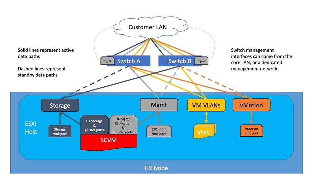
The Cisco HyperFlex system has communication pathways that fall into four defined zones (Figure 12):
● Management Zone: This zone comprises the connections needed to manage the physical hardware, the hypervisor hosts, and the storage controller virtual machines (SCVM). These interfaces and IP addresses need to be available to all staff who will administer the HX system, throughout the LAN/WAN. This zone must provide access to Domain Name System (DNS) and Network Time Protocol (NTP) services, and also allow Secure Shell (SSH) communication. Lastly, for management using Cisco Intersight, these addresses must have access to the internet either directly, or via a proxy server. In this zone are multiple physical and virtual components:
◦ Cisco Integrated Management Controller interfaces used by the servers.
◦ ESXi host management interfaces.
◦ Storage Controller VM management interfaces.
◦ A roaming HX cluster management interface.
◦ Storage Controller VM replication interfaces.
◦ A roaming HX cluster replication interface.
◦ Network switch management interface(s).
● VM Zone: This zone comprises the connections needed to service network IO to the guest VMs that will run inside the HyperFlex hyperconverged system. This zone typically contains multiple VLANs, which are trunked to the Cisco UCS Fabric Interconnects via the network uplinks and tagged with 802.1Q VLAN IDs. These interfaces and IP addresses need to be available to all staff and other computer endpoints which need to communicate with the guest VMs in the HX system, throughout the LAN/WAN.
● Storage Zone: This zone comprises the connections used by the Cisco HX Data Platform software, ESXi hosts, and the storage controller VMs to service the HX Distributed Data Filesystem. These interfaces and IP addresses need to be able to communicate with each other at all times for proper operation. During normal operation in a dual switch configuration, this traffic all traverses just one upstream switch, however there are hardware failure scenarios where this traffic would need to traverse from one switch to the other. For that reason, the VLAN used for HX storage traffic must be able to traverse the network to reach switch A from switch B, and vice-versa. This traffic would not need to be routable to any other parts of the LAN. In this zone are multiple components:
◦ A VMkernel interface used for storage traffic on each ESXi host in the HX cluster.
◦ Storage Controller VM storage interfaces.
◦ A roaming HX cluster storage interface.
● VMotion Zone: This zone comprises the connections used by the ESXi hosts to enable vMotion of the guest VMs from host to host. During normal operation in a dual switch configuration, this traffic all traverses just one upstream switch, however there are hardware failure scenarios where this traffic would need to traverse from one switch to the other. For that reason, the VLAN used for vMotion must be able to traverse the network to reach switch A from switch B, and vice-versa.
Figure 12. Logical Network Design
For the dual switch HyperFlex Edge system configuration, multiple VLANs need to be carried to the Cisco HX-series servers from the upstream switches as tagged traffic. Therefore, the switch interfaces must be configured as trunk ports which allow the required VLANs to pass. The hx-storage-data VLAN must be a separate VLAN ID from the remaining VLANs. Table 10 lists the VLANs created by the HyperFlex installer in Cisco UCS, and their functions.
| VLAN Name |
VLAN ID |
Purpose |
| hx-inband-mgmt |
Customer supplied |
ESXi host management interfaces HX Storage Controller VM management interfaces HX Storage Cluster roaming management interface |
| hx-inband-repl |
Customer supplied |
HX Storage Controller VM Replication interfaces HX Storage Cluster roaming replication interface |
| hx-storage-data |
Customer supplied |
ESXi host storage VMkernel interfaces HX Storage Controller storage network interfaces HX Storage Cluster roaming storage interface |
| vm-network |
Customer supplied |
Guest VM network interfaces |
| hx-vmotion |
Customer supplied |
ESXi host vMotion VMkernel interfaces |
![]() A dedicated network or subnet for physical device management is often used in datacenters. In this scenario, the CIMC interfaces of the servers and the management interfaces of the two switches may be connected to that dedicated network or subnet. This is a valid configuration for HyperFlex Edge installations with the following caveat; the CIMC interfaces must have access to reach Cisco Intersight via the internet or a proxy server and must also have L3 IP connectivity to the subnets used by the hx-inband-mgmt VLAN listed above.
A dedicated network or subnet for physical device management is often used in datacenters. In this scenario, the CIMC interfaces of the servers and the management interfaces of the two switches may be connected to that dedicated network or subnet. This is a valid configuration for HyperFlex Edge installations with the following caveat; the CIMC interfaces must have access to reach Cisco Intersight via the internet or a proxy server and must also have L3 IP connectivity to the subnets used by the hx-inband-mgmt VLAN listed above.
All HyperFlex Edge traffic is configured by default to use standard frames, or to be precise, all communication is configured to send IP packets with a Maximum Transmission Unit (MTU) size of 1500 bytes. HyperFlex Edge clusters can be configured to use jumbo size frames of 9000 bytes during the initial installation for the node-to-node storage traffic. Cisco recommends that this configuration only be used in environments where all connections to the uplink switches are capable of passing jumbo frames, and all ports are properly configured to pass jumbo frames. Due to the additional complexity, plus the possibility of misconfiguration or incompatibility, Cisco recommends that standard MTU frames be enabled for Cisco HyperFlex Edge deployments.
Building upon the configuration of the physical servers set by Cisco Intersight, the following sections detail the design of the elements within the VMware ESXi hypervisors, system requirements, virtual networking, and the configuration of ESXi for the Cisco HyperFlex HX Distributed Data Platform.
The Cisco HyperFlex Edge system has a pre-defined virtual network design at the ESXi hypervisor level. The ESXi host networking design is derived from the configuration of the nodes which is automatically configured via Cisco Intersight during the HyperFlex installation. Eight vNICs are created on the Cisco VIC 1457 card by Cisco Intersight via the CIMC. Four different standard virtual switches are created by the HyperFlex installer, each using two uplinks, which are each serviced by a vNIC defined in the CIMC. The vSwitches created are:
● vswitch-hx-inband-mgmt: This is the default vSwitch0 which is renamed by the ESXi kickstart file as part of the automated installation. The switch has two uplinks, active to switch A and standby to switch B. The default VMkernel port, vmk0, is configured in the standard Management Network port group. A second port group is created for the Storage Platform Controller VMs to connect to with their individual management interfaces. An optional third port group is created for cluster-to-cluster VM snapshot replication traffic. The VLANs are defined in the port groups so they are sent as tagged traffic.
● vswitch-hx-storage-data: This vSwitch is created as part of the automated installation. The switch has two uplinks, active to switch B and standby to switch A, with jumbo frames optionally available. A VMkernel port, vmk1, is configured in the Storage Hypervisor Data Network port group, which is the interface used for connectivity to the HX Datastores via NFS. A second port group is created for the Storage Platform Controller VMs to connect to with their individual storage interfaces. The VLANs are defined in the port groups so they are sent as tagged traffic. Two additional port groups for iSCSI traffic are created but are currently unused.
● vswitch-hx-vm-network: This vSwitch is created as part of the automated installation. The switch has two uplinks, active on both switches A and B, and without jumbo frames. The VLANs are defined in the port groups so they are sent as tagged traffic.
● vmotion: This vSwitch is created as part of the automated installation. The switch has two uplinks, active to switch A and standby to switch B, with jumbo frames optionally available. The IP addresses of the VMkernel ports (vmk2) are configured during the post_install script execution. The VLANs are defined in the port groups so they are sent as tagged traffic.
Table 11 and Figure 13 provide more details about the ESXi virtual networking design as built by the HyperFlex installer by default for servers using the Cisco VIC 1457 for 10/25Gb Ethernet connectivity.
Table 11. Default Virtual Switches
| Virtual Switch |
Port Groups |
Active vmnic(s) |
Passive vmnic(s) |
VLAN IDs |
Jumbo |
| vswitch-hx-inband-mgmt |
Management Network Storage Controller Management Network |
vmnic2 |
vmnic3 |
<<hx-inband-mgmt>> |
no |
| Storage Controller Replication Network |
vmnic2 |
vmnic3 |
<<hx-inband-repl>> |
no |
|
| vswitch-hx-storage-data |
Storage Controller Data Network Storage Hypervisor Data Network |
vmnic5 |
vmnic4 |
<<hx-storage-data>> |
optional |
| vswitch-hx-vm-network |
vm-network-<<VLAN ID>> |
vmnic6 vmnic7 |
<<vm-network>> |
no |
|
| vmotion |
vmotion-<<VLAN ID>> |
vmnic8 |
vmnic9 |
<<hx-vmotion>> |
optional |
Figure 13. ESXi Default Network Design
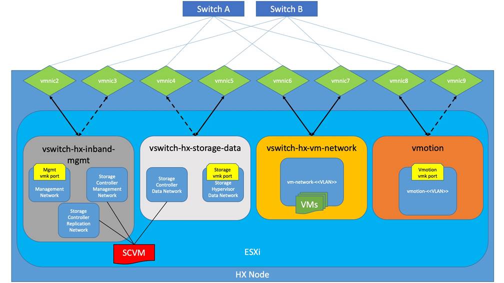
![]() The design shown depicts the configuration when using the Cisco VIC card for 10/25Gb Ethernet connectivy. In this design, vmnic0 and vmnic1 are assigned to the built-in Lan-On-Motherboard (LOM) ports. The design using only 1Gb Ethernet ports is substantially different from what is depicted here.
The design shown depicts the configuration when using the Cisco VIC card for 10/25Gb Ethernet connectivy. In this design, vmnic0 and vmnic1 are assigned to the built-in Lan-On-Motherboard (LOM) ports. The design using only 1Gb Ethernet ports is substantially different from what is depicted here.
VMDirectPath I/O allows a guest VM to directly access PCI and PCIe devices in an ESXi host as though they were physical devices belonging to the VM itself, also referred to as PCI passthrough. With the appropriate driver for the hardware device, the guest VM sends all I/O requests directly to the physical device, bypassing the hypervisor. In the Cisco HyperFlex system, the Storage Platform Controller VMs use this feature to gain full control of the Cisco 12Gbps SAS HBA cards in the Cisco HX-series rack-mount servers. This gives the controller VMs direct hardware level access to the physical disks installed in the servers, which they consume to construct the Cisco HX Distributed Filesystem. Other disks, connected to different controllers, such as the M.2 boot SSDs, remain under the control of the ESXi hypervisor. The configuration of the VMDirectPath I/O feature is done by the Cisco HyperFlex installer and requires no manual steps.
Storage Platform Controller Virtual Machines
A key component of the Cisco HyperFlex system is the Storage Platform Controller Virtual Machine running on each of the nodes in the HyperFlex cluster. The controller VMs cooperate to form and coordinate the Cisco HX Distributed Filesystem, and service all the guest VM IO requests. The storage controller VM runs custom software and services that manage and maintain the Cisco HX Distributed Filesystem. The services and processes that run within the controller VMs are not exposed directly to the ESXi hosts, although the controller VMs are configured to automatically start and stop with the ESXi hosts and protected from accidental deletion. Management and visibility into the function of the controller VMs, and the Cisco HX Distributed Filesystem is done via the HyperFlex Connect HTML management webpage, or a plugin installed to the vCenter server or appliance managing the vSphere cluster. The plugin communicates directly with the controller VMs to display the information requested, or make the configuration changes directed, all while operating within the same web-based interface of the vSphere Web Client. The deployment of the controller VMs are all done by the Cisco HyperFlex installer and requires no manual steps.
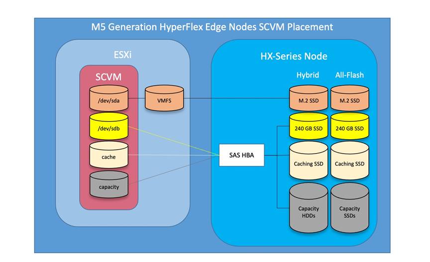
Controller Virtual Machine Locations
The storage controller VM is operationally no different from any other typical virtual machines in an ESXi environment. The VM must have a virtual disk with the bootable root filesystem available in a location separate from the SAS HBA that the VM is controlling via VMDirectPath I/O. The server boots the ESXi hypervisor from the internal M.2 form factor SSD(s). The boot disk is partitioned by the ESXi installer, and all remaining space is used as a VMFS datastore. The controller VM’s root filesystem is stored on a 2.5 GB virtual disk, /dev/sda, which is placed on this VMFS datastore. The controller VM has full control of all the front and rear facing hot-swappable SSDs or HDDs via PCI passthrough. The controller VM operating system mounts the 240 GB SSD, also commonly called the "housekeeping" disk as /dev/sdb, and places HyperFlex binaries and logs on this disk. The remaining disks seen by the controller VM OS are used by the HX Distributed filesystem for caching and capacity layers.
The following figure details the Storage Platform Controller VM placement on the ESXi hypervisor hosts.
Figure 14. All M5 Generation HyperFlex Edge Servers Controller VM Placement
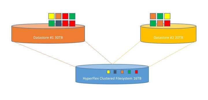
A new HyperFlex cluster has no default datastores configured for virtual machine storage, therefore the datastores must be created using the vCenter Web Client plugin or the HyperFlex Connect GUI. It is important to recognize that all HyperFlex datastores are thinly provisioned, meaning that their configured size can far exceed the actual space available in the HyperFlex cluster. Alerts will be raised by the HyperFlex system in HyperFlex Connect or the vCenter plugin when actual space consumption results in low amounts of free space, and alerts will be sent via auto support email alerts. Overall space consumption in the HyperFlex clustered filesystem is optimized by the default deduplication and compression features.
Since the storage controller VMs provide critical functionality of the Cisco HX Distributed Data Platform, the HyperFlex installer will configure CPU resource reservations for the controller VMs. This reservation guarantees that the controller VMs will have CPU resources at a minimum level, in situations where the physical CPU resources of the ESXi hypervisor host are being heavily consumed by the guest VMs. This is a soft guarantee, meaning in most situations the SCVMs are not using all of the CPU resources reserved, therefore allowing the guest VMs to use them.
Table 12. Controller VM CPU Reservations
| Server Models |
Number of vCPU |
Shares |
Reservation |
Limit |
| All hybrid and all-flash models |
8 |
Low |
10800 MHz |
unlimited |
Since the storage controller VMs provide critical functionality of the Cisco HX Distributed Data Platform, the HyperFlex installer will configure memory resource reservations for the controller VMs. This reservation guarantees that the controller VMs will have memory resources at a minimum level, in situations where the physical memory resources of the ESXi hypervisor host are being heavily consumed by the guest VMs. Table 13 lists the memory resource reservation of the storage controller VMs.
Table 13. Controller VM Memory Reservations
| Server Models |
Amount of Guest Memory |
Reserve All Guest Memory |
| HX-E-220M5SX HXAF-E-220M5SX HXAF240C-M5SD |
48 GB 56 GB when using 7.6 TB disks |
Yes |
| HX-E-240-M5SX HXAF-E-240-M5SX |
72 GB 84 GB when using 7.6 TB disks |
Yes |
Cisco HyperFlex systems are ordered with a factory pre-installation process having been done prior to the hardware delivery. This factory integration work will deliver the HyperFlex servers with the proper firmware revisions pre-set, a copy of the VMware ESXi hypervisor software pre-installed, and some components of the Cisco HyperFlex software already in place. Once on site, the final steps to be performed are reduced and simplified due to the previous factory work. For the purpose of this document, the setup process is described presuming that this factory pre-installation work was done, thereby leveraging the tools and processes developed by Cisco to simplify the process and dramatically reduce the deployment time. The following sections will guide you through the prerequisites and manual steps needed prior to using the HyperFlex installer via Cisco Intersight, how to configure the HyperFlex profiles in Cisco Intersight and perform the installation, then finally how to perform the remaining post-installation tasks.
Prior to beginning the installation activities, it is important to gather the following information:
IP addresses for the Cisco HyperFlex system need to be allocated from the appropriate subnets and VLANs to be used. IP addresses that are used by the system fall into the following groups:
● CIMC Management: These addresses are used and assigned to the CIMC management interfaces of each server. One IP address is assigned to each Cisco HX-series server. These addresses must all be in the same subnet. The CIMC must have IP connectivity to the addresses in the HyperFlex and ESXi Management group, either directly by being in the same subnet, or routable via L3.
● HyperFlex and ESXi Management: These addresses are used to manage the ESXi hypervisor hosts and the HyperFlex Storage Platform Controller VMs. Two IP addresses per node in the HyperFlex cluster are required from the same subnet, and a single additional IP address is needed as the roaming HyperFlex cluster management interface. These addresses can be assigned from the same subnet as the CIMC management addresses, or they may be separate.
● HyperFlex Replication: These addresses are used by the HyperFlex Storage Platform Controller VMs for clusters that are configured to replicate VMs to one another. One IP address per HX node is required, plus one additional IP address as a roaming clustered replication interface. These addresses are assigned to a pool as part of a post-installation activity described later in this document and are not needed to complete the initial installation of a HyperFlex cluster. These addresses can be from the same subnet as the HyperFlex and ESXi management addresses, but it is recommended that the VLAN ID and subnet be unique.
● HyperFlex Storage: These addresses are used by the HyperFlex Storage Platform Controller VMs, and as VMkernel interfaces on the ESXi hypervisor hosts, for sending and receiving data to/from the HX Distributed Data Platform Filesystem. These addresses are automatically provisioned to the nodes from the link-local IPv4 subnet of 169.254.0.0/16 and do not need to be manually assigned prior to installation. Two IP addresses per node in the HyperFlex cluster are assigned from the subnet, and a single additional IP address is assigned as the roaming HyperFlex cluster storage interface. The third octet of the IP addresses is derived from the MAC address pool prefix by converting that value to a decimal number, thereby creating a unique subnet for each cluster, as the subnet mask set on the hosts for these VMkernel ports is 255.255.255.0. The value for the fourth octet is sequentially set, starting with .1 for the overall cluster, then proceeding to .2 for the vmk1(Hypervisor) port of the first server, then .3 for the Storage Controller VM of the first server. The second server would be assigned .4 for its vmk1 port, and .5 for its Storage Controller VM, and this pattern continues for each subsequent server. It is recommended to provision a VLAN ID that is not used in the network for other purposes, and also to use a different VLAN ID for the HyperFlex storage traffic of each cluster, as this is a safer method, guaranteeing that storage traffic from multiple clusters cannot intermix.
● VMotion: These IP addresses are used by the ESXi hypervisor hosts as VMkernel interfaces to enable vMotion capabilities. One or more IP addresses per node in the HyperFlex cluster are required from the same subnet. Multiple addresses and VMkernel interfaces can be used if you wish to enable multi-NIC vMotion, although this configuration would require additional manual steps.
Using the following tables, gather the required IP addresses for the installation of a 4-node HyperFlex Edge cluster, by listing the addresses required, plus an example IP configuration.
![]() Table cells shaded in black do not require an IP address.
Table cells shaded in black do not require an IP address.
Table 14. HyperFlex Edge Cluster IP Addressing
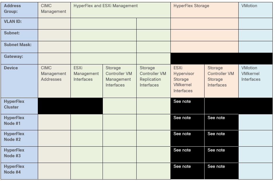
Table 15. HyperFlex Edge Cluster Example IP Addressing
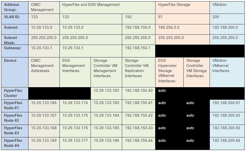
![]() IP addresses for Cisco UCS Management, plus HyperFlex and ESXi Management can come from the same subnet, or can be separate subnets, as long as the HyperFlex installer can reach them both.
IP addresses for Cisco UCS Management, plus HyperFlex and ESXi Management can come from the same subnet, or can be separate subnets, as long as the HyperFlex installer can reach them both.
By default, the HX installation will assign a static IP address to the management interface of the ESXi servers. Using Dynamic Host Configuration Protocol (DHCP) for automatic IP address assignment in not recommended.
DNS servers are highly recommended to be configured for querying Fully Qualified Domain Names (FQDN) in the HyperFlex and ESXi Management group. DNS records need to be created prior to beginning the installation. At a minimum, it is highly recommended to create A records and reverse PTR records for the ESXi hypervisor hosts’ management interfaces. Additional DNS A records can be created for the Storage Controller Management interfaces, ESXi Hypervisor Storage interfaces, and the Storage Controller Storage interfaces if desired.
Using the following tables, gather the required DNS information for the installation, by listing the information required, and an example configuration.
Table 16. DNS Server Information
| Item |
Value |
| DNS Server #1 |
|
| DNS Server #2 |
|
| DNS Domain |
|
| vCenter Server Name |
|
| SMTP Server Name |
|
| HX Server #1 Name |
|
| HX Server #2 Name |
|
| HX Server #3 Name |
|
| HX Server #4 Name |
|
Table 17. DNS Server Example Information
| Item |
Value |
| DNS Server #1 |
10.29.133.110 |
| DNS Server #2 |
|
| DNS Domain |
hx.lab.cisco.com |
| vCenter Server Name |
vcenter.hx.lab.cisco.com |
| SMTP Server Name |
outbound.cisco.com |
| HX Server #1 Name |
hxaf220m5-01.hx.lab.cisco.com |
| HX Server #2 Name |
hxaf220m5-02.hx.lab.cisco.com |
| HX Server #3 Name |
hxaf220m5-03.hx.lab.cisco.com |
| HX Server #4 Name |
hxaf220m5-04.hx.lab.cisco.com |
Consistent time clock synchronization is required across the components of the HyperFlex system, provided by reliable NTP servers, accessible for querying in the CIMC Management network group, and the HyperFlex and ESXi Management group. NTP is used by CIMC, vCenter, the ESXi hypervisor hosts, and the HyperFlex Storage Platform Controller VMs. The use of public NTP servers is highly discouraged, instead a reliable internal NTP server should be used.
Using the following tables, gather the required NTP information for the installation by listing the information required, and an example configuration.
Table 18. NTP Server Information
| Item |
Value |
| NTP Server #1 |
|
| NTP Server #2 |
|
| Timezone |
|
Table 19. NTP Server Example Information
| Item |
Value |
| NTP Server #1 |
ntp1.hx.lab.cisco.com |
| NTP Server #2 |
ntp2.hx.lab.cisco.com |
| Timezone |
(UTC-8:00) Pacific Time |
Prior to the installation, the required VLAN IDs need to be documented, and created in the upstream network if necessary. At a minimum, there are 4 VLANs that need to be trunked to the Cisco UCS Fabric Interconnects that comprise the HyperFlex system; a VLAN for the HyperFlex and ESXi Management group, a VLAN for the HyperFlex Storage group, a VLAN for the VMotion group, and at least one VLAN for the guest VM traffic. If HyperFlex Replication is to be used, another VLAN must be created and trunked for the replication traffic. The VLAN names and IDs must be supplied during the HyperFlex installation wizard.
Using the following tables, gather the required VLAN information for the installation by listing the information required, and an example configuration.
| Name |
ID |
| <<hx-inband-mgmt>> |
|
| <<hx-inband-repl>> |
|
| <<hx-storage-data>> |
|
| <<hx-vm-data>> |
|
| <<hx-vmotion>> |
|
Table 21. VLAN Example Information
| Name |
ID |
| hx-mgmt-133 |
133 |
| hx-repl-150 |
150 |
| hx-storage |
51 |
| vm-network-100 |
100 |
| vmotion-200 |
200 |
Several usernames and passwords need to be defined or known as part of the HyperFlex installation process. Using the following tables, gather the required username and password information by listing the information required and an example configuration.
Table 22. Usernames and Passwords
| Account |
Username |
Password |
|
| CIMC Administrator |
admin |
<<cimc_admin_pw>> |
|
| ESXi Administrator |
root |
<<esxi_root_pw>> |
|
| HyperFlex Administrator |
admin |
<<hx_admin_pw>> |
|
| vCenter Administrator |
<<vcenter_administrator>> |
<<vcenter_admin_pw>> |
|
Table 23. Example Usernames and Passwords
| Account |
Username |
Password |
| CIMC Administrator |
admin |
Cisco123 |
| ESXi Administrator |
root |
CIsco123!! |
| HyperFlex Administrator |
admin |
CIsco123!! |
| vCenter Administrator |
administrator@vsphere.local |
!Q2w3e4r |
Install the HX-Series rack-mount servers according to their corresponding hardware installation guides listed below.
HX220c M5 Server: https://www.cisco.com/c/en/us/td/docs/hyperconverged_systems/HX_series/HX220c_M5/HX220c_M5.html
HX240c M5 Server: https://www.cisco.com/c/en/us/td/docs/hyperconverged_systems/HX_series/HX240c_M5/HX240c_M5.html
The physical layout of the HyperFlex system is described in the Physical Topology section. The HX-series rack-mount servers need to be cabled properly before beginning the installation activities. For the dual redundant 10/25GbE switch configuration, two links per server are connected, one to each switch, plus a third 1GbE link for the CIMC interface. It is important to maintain consistency of the port numbers used, for example always using ports 1 and 2 on the Cisco VIC cards and connecting them to the same ports of the upstream switches. In this example, server #1 has both ports connected to port 1 of each switch, while server #2 has both ports connected to port 2 of each switch. Cisco recommends the use of a dedicated 1GbE port for CIMC traffic, although it is possible to configure the CIMC to send traffic over the same trunked 10/25GbE interfaces of the Cisco VIC cards if no other 1GbE interfaces are available.
Figure 16. Physical Cabling Example
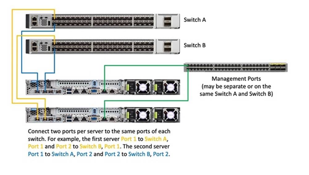
Configure the following settings for the CIMC management interface of each server prior to beginning the HyperFlex installation.
Cisco HX-series servers are shipped with the CIMC configuration set to the default, which will use DHCP for IP address assignment, and a default admin password of "password". To set the initial configuration of the CIMC, follow these steps:
1. Connect the included KVM dongle to the KVM connector on the front of the first server being configured in the Cisco HyperFlex Edge cluster. Plug in a monitor and keyboard to the KVM dongle, then turn the server on.
2. As the server finishes the POST, press the F8 key when indicated on the screen to enter the CIMC setup.
3. Enter the default username of "admin" and password of "password" if prompted.
4. Set the NIC mode to Dedicated and NIC Redundancy to None by using the arrow up/down keys and pressing the space bar to enable or disable the options on the screen. Other settings should only be enabled when forced to use the Cisco VIC (MLOM) for trunked traffic, which also requires the VLAN ID to be set.
5. Disable the DHCP option, then enter the IP address, Subnet Mask, Gateway, and DNS server IP addresses in the appropriate fields. Using DHCP is discouraged unless reservations are also used to ensure consistent IP addressing of the CIMC.
6. Press F10 to save the settings, then after 45 seconds press F5 to refresh.
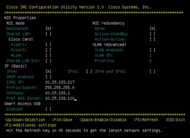
7. Press F1 to move to the second page of settings.
8. Modify the hostname of the CIMC to make it easier to identify the server when it is managed by Cisco Intersight and disable Dynamic DNS.
9. Change the default admin password by entering a new password in the two fields.
10. Press F10 to save the settings, then after 45 seconds press F5 to refresh.
11. Press ESC to quit the CIMC configuration utility.
12. Repeat steps 1-11 for all remaining servers to be used in the Cisco HyperFlex Edge cluster.
Ensuring all components have consistent time is crucial to the proper function of Cisco HyperFlex. To configure NTP for the CIMC of the HX-series servers, follow these steps:
1. Using a web browser, navigate to the IP address of hostname of the CIMC of the first HX-series server being used for the HyperFlex Edge cluster.
2. Enter the default username "admin" and the password as configured in the previous steps, then click Log In.
3. Click the link on the CIMC homepage for Select Timezone.
4. In the pop-up windows, select the desired timezone for the CIMC from the dropdown list, then click OK.
5. At the homepage, click Save Changes to apply the timezone change.
6. Click the menu icon in the top left-hand corner, then click Admin in the menu that appears, then click Networking.
7. Click the NTP Setting tab.
8. Click to enable NTP and click OK to the alert that appears. Enter one or more NTP server IP addresses or hostnames, then click Save Changes.
9. Click the Refresh link at the top of the screen. The NTP status should display as synchronized after a few minutes have passed.
10. Repeat steps 1-9 for all remaining servers to be used in the Cisco HyperFlex Edge cluster.
Your Cisco servers’ firmware version should be correct as shipped from the factory, as documented in the Software Components section. This document is based on Cisco HX-Series bundle software versions 4.1(2f). If the firmware version of the servers is older than this version, the firmware must be upgraded to match the requirements prior to completing any further steps. To upgrade the servers’ firmware version, using the Host Upgrade Utility (HUU) bundle, refer to these instructions: https://www.cisco.com/c/en/us/td/docs/unified_computing/ucs/c/sw/lomug/4_0/b_huu_4_0_2.html
A Cisco Intersight account is required for this solution. To create your Intersight account you must have a valid Cisco ID first. If you do not have a Cisco ID yet, the account can be generated in this way:
1. Visit https://intersight.com from your workstation.
2. Click Sign In with Cisco ID.
3. On the Cisco Login page, you have the option to log into an Existing Account or click Register Now to create a new account.
4. Click Register Now and provide the requested information to create a cisco.com account.
5. Once a valid account is created, it can be used to log into Cisco Intersight.
Consider the following prerequisites pertaining to Intersight connectivity:
● Before installing the HX cluster on a set of HX-series servers, make sure that the device connectors of the servers are properly configured to connect to Cisco Intersight and claimed.
● All device connectors must properly resolve svc.intersight.com and allow outbound initiated HTTPS connections on port 443. The current version of the HX Installer supports the use of an HTTP proxy.
● All HyperFlex controller VM management interfaces must properly resolve svc.intersight.com and allow outbound initiated HTTPS connections on port 443. The current version of HX Installer supports the use of an HTTP proxy if direct Internet connectivity is unavailable.
● IP connectivity (L2 or L3) is required from the CIMC management IP on each server to all of the following: ESXi management interfaces, HyperFlex controller VM management interfaces, and vCenter server. Any firewalls in this path should be configured to allow the necessary ports as outlined in the Hyperflex Hardening Guide: https://www.cisco.com/c/dam/en/us/support/docs/hyperconverged-infrastructure/hyperflex-hx-data-platform/HX-Hardening_Guide.pdf
● When redeploying HyperFlex on the same servers, new controller VMs must be downloaded from Intersight into all ESXi hosts. This requires each ESXi host to be able to resolve svc.intersight.com and allow outbound initiated HTTPS connections on port 443. Use of a proxy server for controller VM downloads is supported and can be configured in the HyperFlex Cluster Profile if desired.
● Post-cluster deployment, the new HyperFlex cluster is automatically claimed in Intersight for ongoing management.
Claim Devices in Cisco Intersight
The CIMC device connector allows Cisco Intersight to manage the Cisco HX-series HyperFlex servers and claim them for cloud-based management. To claim devices in Cisco Intersight, follow these steps:
1. Log into the CIMC web interface of the Cisco HX-series servers that will comprise the new Cisco HyperFlex Edge cluster being installed.
2. Click the menu icon in the top left-hand corner, then click Admin in the menu that appears, then click Device Connector.
3. Note that the CIMC shows a status of "Not Claimed." Copy the Device ID and the Claim Code by clicking the small clipboard icons.
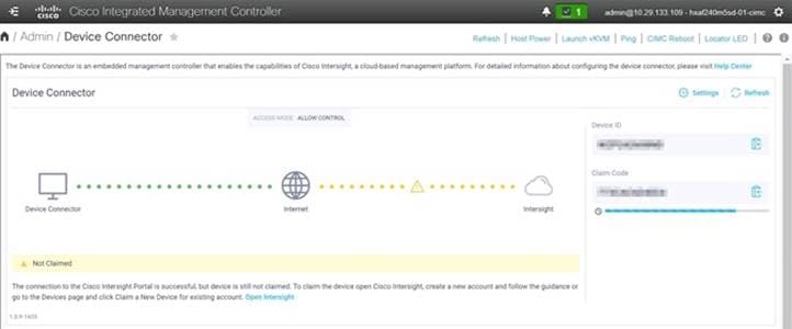
4. Open a web browser and navigate to the Cisco Intersight Cloud Management platform https://intersight.com/.
5. Login with your Cisco ID and password. If this is the first time using Intersight, it is recommended you take a site tour to be guided through some main features.
6. To Claim a new device, from the left-hand Navigation pane, underneath ADMIN, click Targets, in the Targets window, choose Claim a New Target at the right top corner.
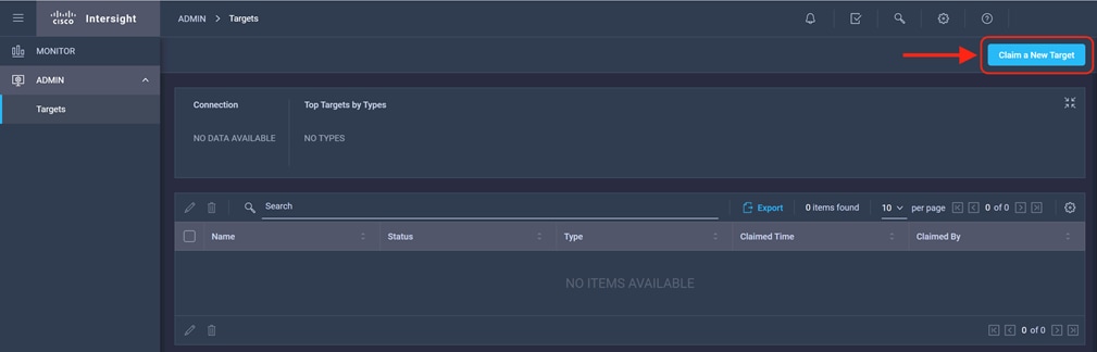
7. Select the target type named Cisco UCS Server (Standalone), then click Start.
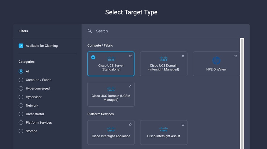
8. Enter the Device ID and Claim Code obtained from Cisco UCS management GUI. Use copy and paste for accuracy. Click Claim.
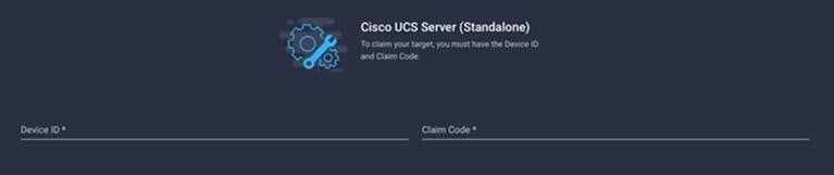
9. In the Targets window, the server should now show as a claimed device.
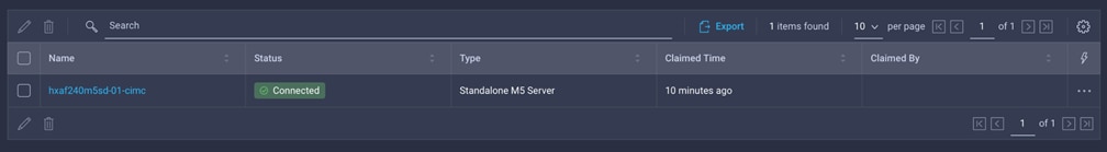
10. Click the Refresh link in the CIMC Device Connector screen. The Device Connector now shows this device is claimed.
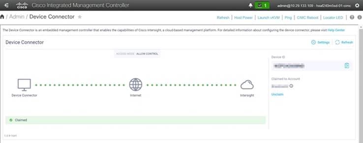
11. Repeat steps 1-10 for all remaining servers to be used in the Cisco HyperFlex Edge cluster.
HyperFlex Edge Cluster Creation
Cisco Intersight provides an installation wizard to install, configure, and deploy Cisco HyperFlex Edge clusters. The wizard constructs a pre-configuration definition of a Cisco HyperFlex cluster called an HX Cluster Profile. The cluster profile is policy driven with administrator-defined sets of rules and operating characteristics such as the node identity, interfaces, and vCenter connectivity. Every active node in the Cisco HyperFlex Edge cluster must be associated with an HX Cluster Profile. After the user inputs all configuration settings, the installation wizard will validate and deploy the HX Cluster Profile on the Cisco HX-series nodes, creating the new HyperFlex cluster. You can clone a successfully deployed HX Cluster Profile, and then use that copy as the basis to easily create many more new clusters.
To install and configure a HyperFlex standard cluster with Intersight, follow these steps:
1. Login to Cisco Intersight Cloud Management platform https://intersight.com/ with your Cisco ID and password.
2. From the left-hand navigation pane, underneath CONFIGURE, choose Profiles. On the Profiles page, click the HyperFlex Cluster Profile tab then click Create HyperFlex Cluster Profile.
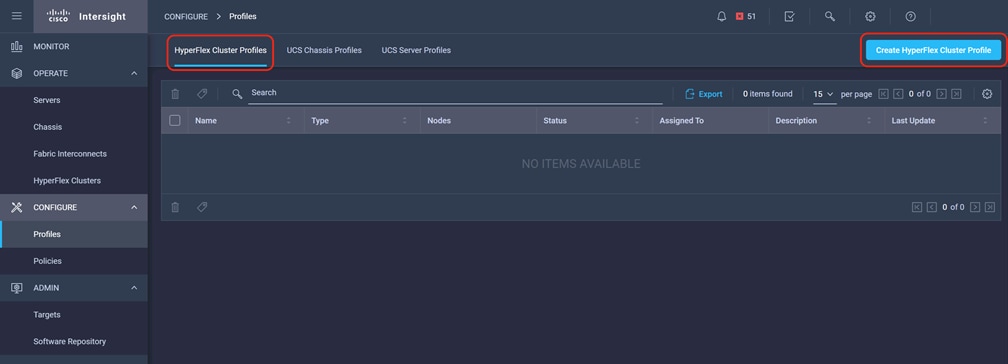
3. The HyperFlex Cluster Profile installation wizard is displayed. On the first page you must choose between installing a standard or edge cluster. Choose Edge then click Start.
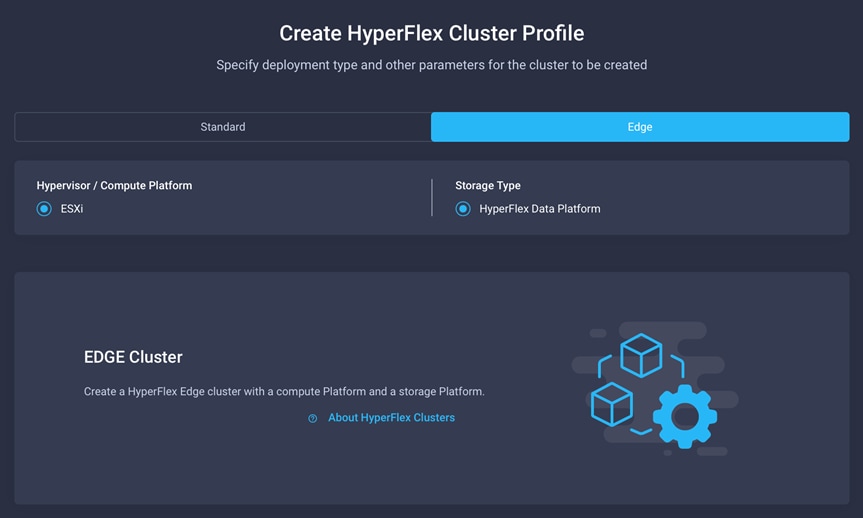
4. On the General page, select the Intersight Organization as appropriate and enter a cluster name under Name. This cluster name must be unique and will be used as the HXDP cluster name, vCenter cluster name, and the Intersight cluster name. Select the appropriate HXDP version and add any desired description or tags for this cluster for good reference, then click Next.
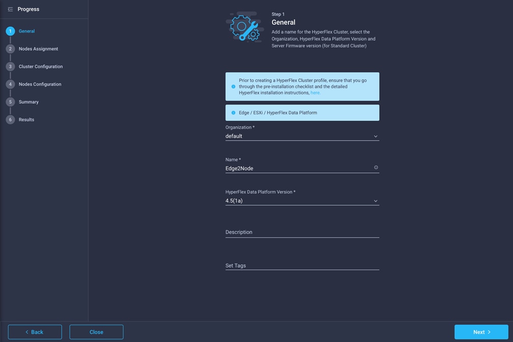
5. The next section allows you to choose which servers in the UCS domain will be assigned to this cluster. Servers can be searched for or filtered by name, model number or serial number. If desired, click Assign Nodes Later in order to complete this step at a later time. Check the box to the left of each server to assign to this cluster, then click Next.
![]() Technically, up to 8 Edge nodes are allowed, but if more than 4 servers are selected Intersight will show a warning which must be dismissed to continue. In addition, clusters with more than 4 nodes will require HXDP Datacenter licensing.
Technically, up to 8 Edge nodes are allowed, but if more than 4 servers are selected Intersight will show a warning which must be dismissed to continue. In addition, clusters with more than 4 nodes will require HXDP Datacenter licensing.
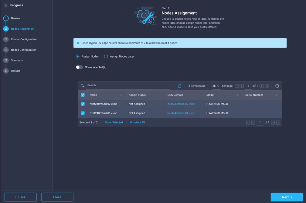
6. In the next section the policies are created to be used as part of the HyperFlex Cluster Profile. At any time, it is possible to click Close to save this cluster profile configuration and then return to complete the work at a later time.
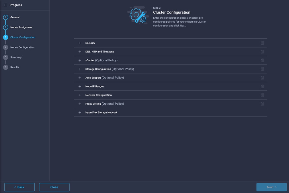
7. Click + to expand Security configuration. Enter root as the Hypervisor administrative user. Click the check box if the hypervisor on this node uses the factory default password. Input a new user supplied password for the root account of the Hypervisor and a user supplied password for the HX controller VM. Once you close the security configuration by collapsing the section via clicking the minus ("-") symbol, clicking another section below, the settings are automatically saved to a policy named <HX-Cluster-Name>-local-credential-policy. This policy is reusable and can be selected for use when you create your next HX Cluster Profile.
8. (Optional) To choose an existing policy for one section of the cluster profile, at the policy line, click Select Policy icon, to choose the desired policy from the available policy list and click Select.
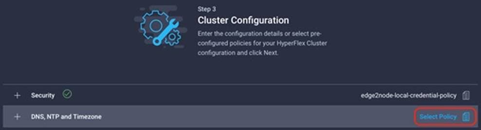
9. Click + to expand DNS, NTP and Timezone configuration. Choose a time zone from the drop-down list, then enter the DNS server and NTP server information. Click + to add secondary DNS or NTP servers. Once you close the DNS, NTP, and Timezone configuration, the settings are automatically saved to a reusable policy named <HX-Cluster-Name>-sys-config-policy.
10. Click + to expand vCenter configuration. Enter the vCenter server FQDN or IP address, and an administrative username and password. Enter the Datacenter name in vCenter hosting the HX Edge cluster. The Datacenter name can match an existing datacenter object in the vCenter environment, if it does not match an existing object a new Datacenter will be created with the name supplied. Once you close the vCenter configuration, the settings are automatically saved to a reusable policy named <HX-Cluster-Name>-vcenter-config-policy.
11. Click + to expand Storage configuration. Select Clean Up Disk Partitions if performing a reinstallation on top of an existing deployment. If deploying a VDI environment on a hybrid HX cluster, check the box to enable filesystem optimizations. Once you close the Storage configuration, the settings are automatically saved to a reusable policy named <HX-Cluster-Name>-cluster-storage-policy.
12. Click + to expand Auto Support configuration. Check the box to enable Auto-Support. Enter your email address for the service ticket notifications. Once you close the Auto Support configuration, the settings are automatically saved to a reusable policy named <HX-Cluster-Name>-auto-support-policy.
13. Click + to expand Node IP Ranges. Enter a starting IP address, an ending IP address, the subnet mask, and gateway for the management IP range. IPs from this range will be automatically assigned to the ESXi hosts’ management interfaces during the node configuration step. If only the management network IPs are entered, the same range will be used for both ESXi management and HX Controller VM management IPs. If you desire to use a second, non-contiguous range of IPs for the HX Controller VMs, you may optionally enter starting and ending IP addresses, subnet mask and gateway for the Controller VM management network IP range. Note these two IP ranges must fall within the same IP subnet and VLAN. Once you close the IP & Hostname configuration, the settings are automatically saved to a reusable named <HX-Cluster-Name>-node-config-policy.
14. Click + to expand Network configuration. Select the network configuration of 1GbE or 10GbE+ as appropriate. If 10GbE+ is selected, enter a value for the fourth byte of the MAC address pool which will be used to assign MAC addresses to the servers’ vNICs, for example 00:25:B5:25. In most cases it is sufficient to enter the same value in the starting and ending field, and all generated MAC addresses will have the same first 4 byte values. It is important to note as detailed earlier that the Hyperflex storage network IP addresses will be derived in part from the MAC address pool prefix entered here. In order to prevent any IP address overlaps, it is important to use a unique MAC address pool prefix for each HyperFlex cluster. Enter a VLAN ID which will be used for management of the Cisco HyperFlex cluster. Lastly, if the network switches are configured to properly support large MTU packets, check the box to enable Jumbo Frames. Once you close the Network configuration, the settings are automatically saved to a reusable policy named <HX-Cluster-Name>-cluster-network-policy.
15. If necessary, click + to expand Proxy Setting. Enter the Proxy server hostname, port, username, and password.
16. Click + to expand HyperFlex Storage Network configuration. Enter the VLAN ID for the HyperFlex data storage network. It is highly recommended to use a unique storage VLAN per cluster if multiple clusters are to be deployed within the same network. To avoid possible conflicts this policy is not saved for reuse.
17. Now that all the policies are configured, the saved or selected policies will be listed in this page. Click Next to proceed to the Nodes Configuration page.
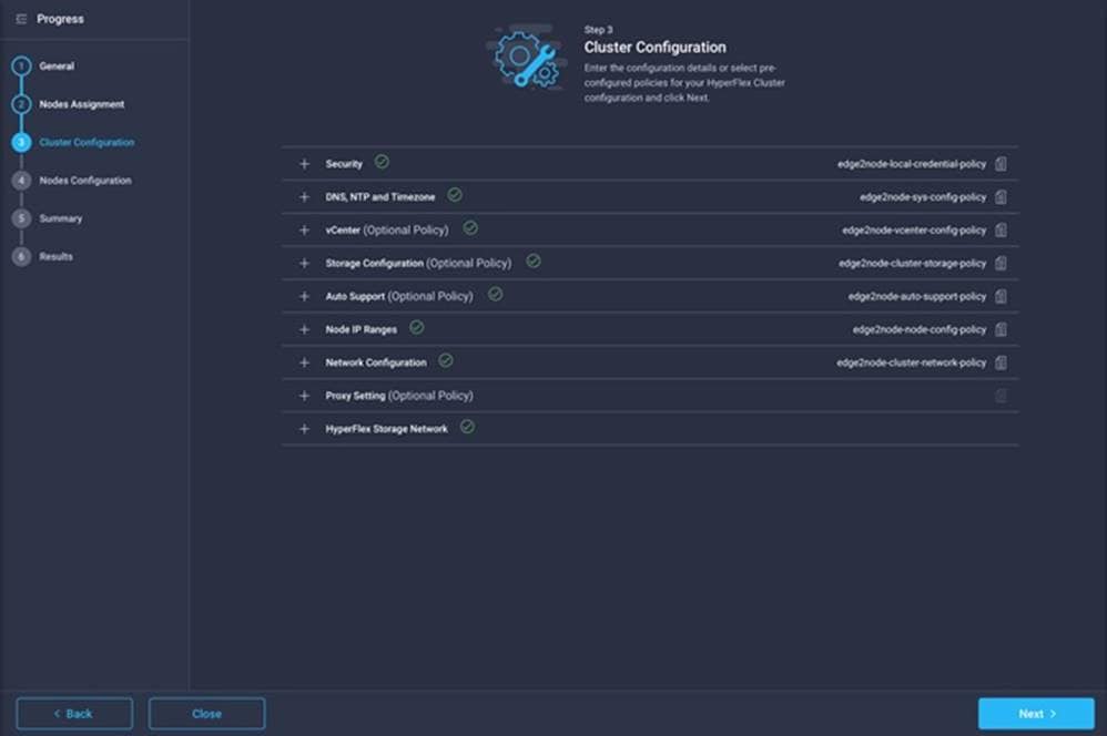
18. Click Next to navigate to the Nodes Configuration page. Enter the HyperFlex cluster management IP address, and also enter the MAC address prefix matching the prefix entered as part of the network configuration policy done earlier. Select the desired Replication Factor, then click Expand All to view the node configuration for all of the HyperFlex cluster nodes. The hostnames will be automatically set, and IP address assignments will be drawn from the pool defined in the previous step which should match the ordering of the servers. The hostnames and IP addresses can be modified if necessary, for example if the automatic naming prefix does not result in the desired naming convention. Modify the names and IP addresses as necessary, then click Next.
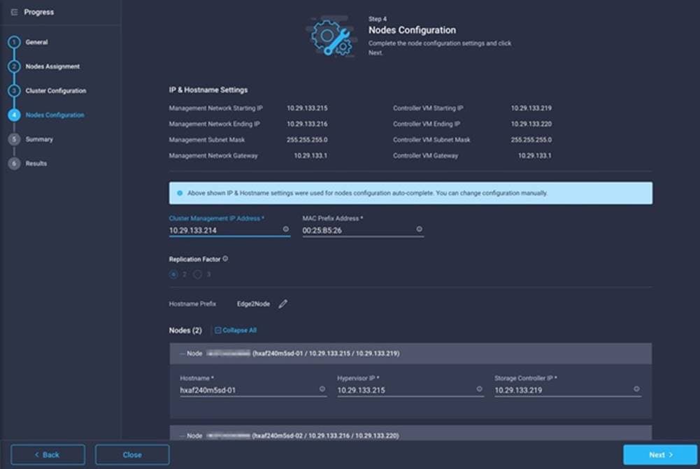
19. On the Summary page, review the configuration and policies to check if there are any warnings or errors. In this example, the warning about enabling replication factor of 2 can be ignored as this is the only valid choice for a 2-node cluster. Click Validate to validate the HyperFlex Edge cluster configuration only without starting the deployment. This will start a series of hardware, software, and environmental checks that will take a few minutes to complete. Alternatively, click Validate & Deploy to complete validation and deployment together. This document follows the path of performing Validate & Deploy in a single step.

20. Optionally, you can click Close to complete deployment later. Installation time will vary based on network bandwidth, but typically takes about 1-2 hours. You can remain on the results page to watch cluster deployment progress in real time. Alternatively, you may click Close to send the task into the background and navigate elsewhere within Intersight. To return to this results view, navigate back to the CONFIGURE > Policies > HyperFlex Cluster Profile list view and select the cluster name.
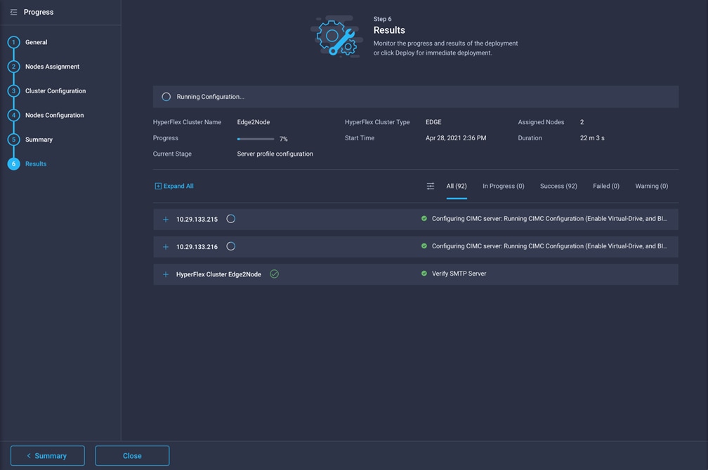
21. When deployment has completed successfully, click OK.
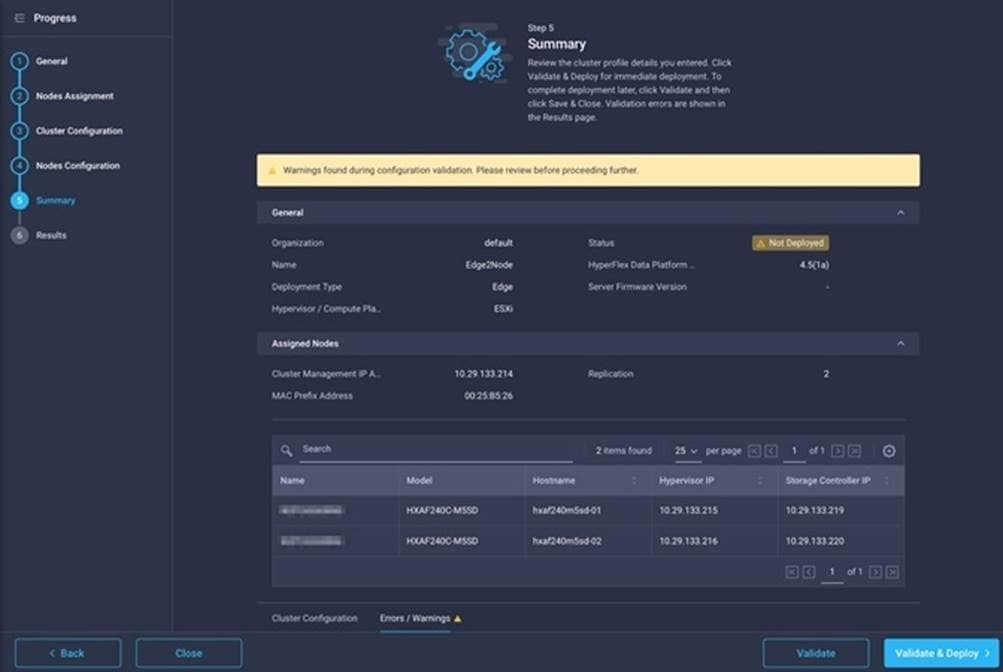
22. Once back on the CONFIGURE > Profiles > HX Cluster Profile page, find the newly deployed HX cluster profile with a status of OK.
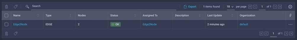
Cisco Intersight Service for Terraform
Cisco Intersight Service for Terraform (Cisco IST) is a new service offering within Cisco Intersight, that extends the ability to run Terraform plans from the cloud-based service offered by Hashicorp, named Terraform Cloud for Business, against non-public services and endpoints within your internal data centers. In many organizations, Terraform plans are created and executed on the local workstations of individual contributors. To overcome the decentralized nature of this process, and to gain collaboration features, execution tracking and logging, Hashicorp has created Terraform Cloud. Terraform Cloud allows for an organization to link their Terraform plans from a version control repository, such as GitHub, into a web-based portal where the plans can be executed from a centralized location. Each execution of a plan is logged, and the results of each execution are saved, providing the organization a way of auditing the use of the Terraform plans and their outcomes. Terraform Cloud is an excellent solution for teams of administrators who use Terraform plans to create and modify resources, when executing plans against cloud-native systems, for example using Terraform Cloud to execute a plan against Cisco Intersight to create a Cisco HyperFlex cluster profile.
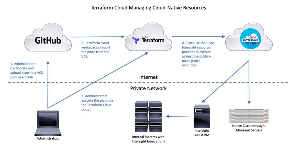
Terraform Cloud is limited to communications with other systems, APIs and services that are publicly accessible on the internet. To overcome this restriction, Hashicorp developed the ability to deploy a Terraform agent which can be installed on a local system within your internal network, which in turn has direct access to the systems, APIs, and services inside of the private data center. The Terraform Cloud Agent acts as a bridge between the public Terraform Cloud service and the private resources being managed by the Terraform plans. Workspaces in Terraform Cloud can be configured to use the connected Terraform Cloud Agent when plans are executed, so the plans are executed on the agent itself, but the initiation and logging of the executions still happens in the Terraform Cloud portal. In this way, non-publicly accessible systems can be managed via Terraform Cloud in the same way that cloud-native systems are.
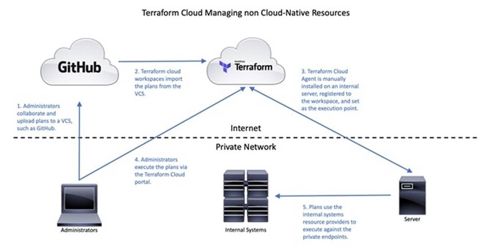
One consideration of the Terraform Cloud agent is that the agent deployment, configuration, and maintenance becomes a new ongoing management task for the on-site administrative staff. To mitigate this ongoing work, Cisco IST has been developed in cooperation with Hashicorp, to automate the deployment and management of a Terraform Cloud agent, running on a Cisco Intersight Assist appliance. Cisco Intersight Assist is an add-on component to Cisco Intersight, to facilitate the ability to use Cisco Intersight to manage local systems and resources that are not native to the Cisco Intersight ecosystem. For example, Cisco Intersight Assist can enable management of virtualized systems by connecting Intersight in the cloud to VMware vCenter, or enable Cisco Intersight to manage storage arrays from partners such as Pure Storage. Cisco Intersight Assist is deployed as a local VM inside the data center, and acts as a bridge between Intersight in the cloud and the private resources in the data center which have integrations developed for Cisco Intersight. Because Cisco Intersight Assist already operates in the same paradigm as Terraform Agents for Terraform Cloud, it is a natural extension to create a Terraform Agent on the Cisco Intersight Assist VM, thereby enabling the ability to run Terraform plans against internal resources accessible from the Intersight Assist VM.
For example, Cisco IST could be used to run Terraform plans from Terraform Cloud for Business to configure Cisco APIC for Remote Leaf switches, in order to support a new Cisco HyperFlex installation. Because Cisco APIC is not exposed to the internet, and there is no current integration with Cisco Intersight, the only options for using Terraform to configure Cisco APIC would be from a local workstation, or via Cisco IST. Furthermore, Cisco IST automates the lifecycle of the Terraform Cloud Agent, so local staff are relieved of that additional burden.
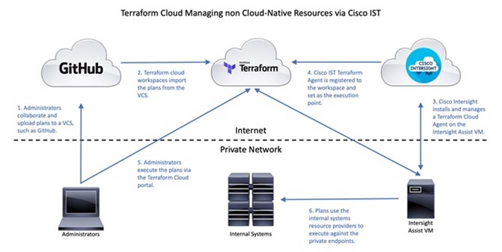
The enhanced flexibility of using Cisco Intersight, Cisco Intersight Assist, and Cisco IST, means that all resources which can be managed by Cisco Intersight natively, such as Cisco UCS servers, plus systems managed via Cisco Intersight Assist, and systems not managed by Cisco Intersight at all, can all be configured using Terraform plans in Terraform Cloud for Business. Workspaces are created in Terraform Cloud for Business, each with their own repository of plans, and the execution location of each workspace can be set independently. Systems and resources that are managed by Cisco Intersight, or via Cisco Intersight Assist can be created or modified using plans in a workspace whose execution is set to the cloud. Systems and resources which are internal, and not manageable by Cisco Intersight can use plans in a workspace whose execution point is the Cisco IST agent inside the data center, running on the Cisco Intersight Assist VM.
To get started using Cisco IST, the following requirements must be met:
● Cisco Intersight Service for Terraform requires licensing for Hashicorp Terraform Cloud for Business, which is a distinct offering above the standard Terraform Cloud service. Contact your local Cisco sales team or Cisco partner to inquire about Terraform Cloud for Business accounts.
● Cisco Intersight Advantage or Premier licensing must be purchased and activated in the Cisco Intersight cloud-based portal.
● A Cisco Intersight Virtual Appliance must be installed. During the initial configuration of the Cisco Intersight Virtual Appliance, the system is designated as an Intersight Assist machine. More details on the installation of Cisco Intersight Assist can be found here: https://www.cisco.com/c/en/us/td/docs/unified_computing/Intersight/cisco-intersight-assist-getting-started-guide/m-installing-cisco-intersight-assist.html
● After the Cisco Intersight Assist VM is installed and claimed in your Cisco Intersight account, a connection is established between Cisco Intersight and Terraform Cloud, then the cloud agent is deployed. More details on the configuration of the cloud connection and agent deployment can be found here: https://cdn.intersight.com/components/an-hulk/1.0.9-750/docs/cloud/data/resources/terraform-service/en/Cisco_IST_Getting_Started_Guide.pdf
● Once the cloud agent is deployed and the agent pool is created in Terraform Cloud, either a new workspace can be created, or the existing workspace settings can be changed to use the new agent pool. Each plan execution from that workspace will now execute on the Cisco IST cloud agent inside the datacenter.
With Cisco IST now available, the Terraform plans provided as examples in this document can be run in various combinations. For example, the Cisco HyperFlex Edge setup plans can be run either locally, or in Terraform Cloud, as in either case the endpoint being contacted is the Cisco Intersight cloud-based service. The Terraform plans for Cisco ACI configuration can be run locally, or be run via Cisco IST, as Cisco APIC is not natively manageable via Cisco Intersight.
Installation with Hashicorp Terraform
The proliferation of small virtualized systems in numerous locations can become a deployment and management challenge. The capability to install, configure, and monitor systems spread out over large geographic distances requires a different framework that does not require IT staff to travel and be on site physically to perform all the installation tasks. The Cisco Intersight™ platform allows the remote installation, management, and monitoring of Cisco HyperFlex Edge systems from our centralized cloud-based web portal.
Despite this advancement, using a web-based GUI to deploy multiple systems can be time consuming, repetitive, and at risk of human error. To mitigate these risks, customers can use the powerful Cisco Intersight API and the enterprise-class end-state configuration tool Hashicorp Terraform. Using the Cisco Intersight Terraform provider to communicate with the Cisco Intersight API, customers can deploy Cisco HyperFlex systems with minimal use of the GUI. Using a scriptable tool such as Terraform, customers can more quickly implement widespread deployments with fewer errors, because configurations are predefined in variable text files. This approach is often referred to as Infrastructure as Code (IaC). These scripts and configuration files can be created and validated prior to deployment and also retained in a version control system (VCS) repository for record keeping to track configuration history.
Hashicorp Terraform evaluates the desired configuration state as defined in the script and variables, then performs all the necessary create, read, update and/or delete (CRUD) operations against Cisco Intersight via the provider, to reach the desired end-state. While Terraform cannot automate the entire process, it can be a useful tool for IT staff when deploying several Cisco HyperFlex Edge systems. As an example, local or regional IT staff can perform the basic setup functions of a new cluster, such as the physical installation, cabling and the CIMC configuration. Afterwards, higher level remote IT staff can claim the devices in Cisco Intersight, and use Terraform to configure the cluster profiles in Cisco Intersight, then trigger the installations. Terraform plans can be executed on a local workstation using local files, or they can be run via Terraform Cloud, where the scripts and variables are synchronized with a remote VCS, such as GitHub. This initial demonstration of using Terraform for installations will use a local workstation.
All prerequisites for installation using Hashicorp Terraform match those when installing manually using Cisco Intersight, as documented in the previous Prerequisites section. The Cisco HyperFlex HX-Series servers must be physically racked, cabled, their CIMC configured, and the servers claimed in Cisco Intersight before the Terraform-based installation procedure can begin.
Setup of the solution begins with a management workstation that has access to Cisco Intersight and with a working installation of Terraform. The management workstation commonly runs a variant of Linux or MacOS for ease of use with these command-line-based tools. Instructions for installing and configuring the workstation and Terraform are not included in this document. A guide for getting started with Hashicorp Terraform can be found at the following link: https://learn.hashicorp.com/terraform
To use the Terraform scripts demonstrated in this document, the management workstation must also have a working installation of Git and access to the Cisco UCS Compute Solutions public GitHub repository, using the terraform-intersight-hyperflex collection. The Terraform scripts used in this document are cloned from the public repository, located at the following link: https://github.com/ucs-compute-solutions/terraform-intersight-hyperflex
Alternatively, the example scripts can be modified and copied to a GitHub repository which is then linked with a Terraform Cloud workspace. The plans would then be executed via Terraform Cloud instead of using the examples contained here, which show the plan execution from a local workstation.
The first step in the process is to clone the GitHub collection named terraform-intersight-hyperflex to a new empty folder on the management workstation. Cloning the collection creates a local copy, which is then used to run the playbooks that have been created for this solution. To clone the GitHub collection, follow these steps:
1. From the management workstation, create a new folder for the project. The GitHub collection will be cloned in a new folder inside this one, named terraform-intersight-hyperflex.
2. Open a command-line or console interface on the management workstation and change directories to the new folder just created.
3. Clone the GitHub collection using the following command:
git clone https://github.com/ucs-compute-solutions/terraform-intersight-hyperflex.git
4. Change directories to the new folder named terraform-intersight-hyperflex.
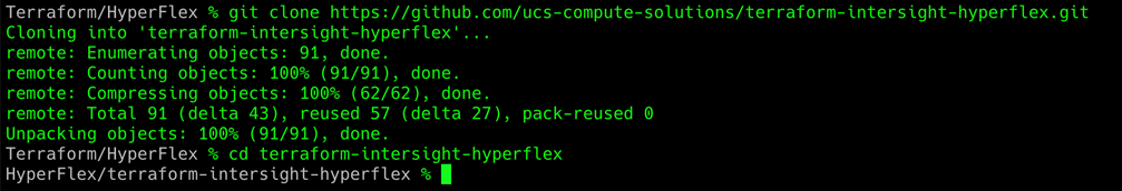
Configure Cisco Intersight API Access
Before Terraform can access the Cisco Intersight API, you must configure the cloned terraform.tfvars file with information specifying the location of an API private key file and an API key ID. The terraform.tfvars file as cloned refers to the default name of the API key file as SecretKey.txt found in the same folder as the terraform.tfvars file. The key file and the ID are created and retrieved from within Cisco Intersight. To configure Cisco Intersight API access, follow these steps:
1. Using a supported web browser, log in to Cisco Intersight at https://www.intersight.com.
2. Click the gear icon in the top-right corner. Then click Settings.
3. Click API Keys in the menu on the left.
4. Click Generate API Key in the top-right corner.
5. Enter a description for the API key, such as Terraform, then click Generate.
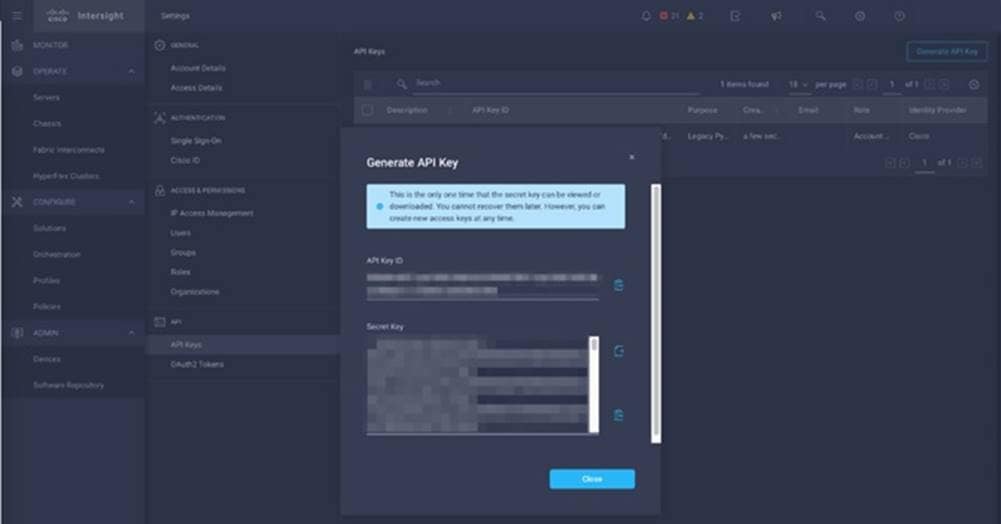
6. Click the icon to copy the API key ID and then paste the key ID in between the quotation marks in the terraform.tfvars file, in the line beginning with api_key = "".
7. Click the icon to save the secret key to a local text file. Note the location of the downloaded file and move the SecretKey.txt file to the terraform-intersight-hyperflex folder where the GitHub repository was cloned.
Terraform uses variables like many other scripting tools and languages in order to set temporary values for each run of the script. The variables are defined in the file named variables.tf, and their values are set in the file named terraform.tfvars. For each Cisco HyperFlex Edge cluster to be created, the default terraform.tfvars file can be modified, or a copy can be made with a unique name and referenced with each run of the script.
A description is provided below for each of the variables in the terraform.tfvars file included in the GitHub repository. The values should be modified as appropriate for the cluster being installed in your environment.
● api_key: Enter the Cisco Intersight API key ID from the earlier step when access to Cisco Intersight via the API was configured.
● api_key_file: Enter the location and name of the Cisco API key file.
● intersight_organization_name: Enter the name of the Intersight organization in which to create the HyperFlex cluster profile and policies. The servers must also be configured within Cisco Intersight to be a part of this organization. The default organization is named "default".
● cluster_name: Enter the name of the new Cisco HyperFlex Edge cluster.
● disk_cleanup: Enter "true" to clean up any existing data on the disks, otherwise enter "false".
● vdi_opt: Enter "true" to optimize the cluster for virtual desktop environments, otherwise enter "false".
● laz_config: Must be set to "false" as it is not applicable to Cisco HyperFlex Edge installations.
● edge_cluster: Enter "true" to configure a Cisco HyperFlex Edge cluster.
● jumbo_frame: Enter "true" to enable jumbo frames, otherwise enter "false".
● uplink_speed: Enter "1G" for 1GbE connectivity, otherwise enter "10G" for 10GbE or 25 GbE connectivity.
● replication: Enter the replication factor of 2 or 3. For 2 node clusters, only factor 2 is valid.
● mgmt_vlan_name: Not applicable to Cisco HyperFlex Edge installations, can be left blank "".
● mgmt_vlan_id: Enter the VLAN ID for the management VLAN.
● hx_mgmt_ip: Enter the management IP address of the Cisco HyperFlex Edge cluster.
● hx_ip_start: Enter the first IP address of the range to be assigned to the SCVMs of the new cluster.
● hx_ip_end: Enter the last IP address of the range to be assigned to the SCVMs of the new cluster.
● hx_netmask: Enter the netmask of the subnet used for HyperFlex management.
● hx_gateway: Enter the gateway IP address of the subnet used for HyperFlex management.
● mac_prefix: Enter the first 4 bytes of the MAC address that will be assigned to the vNICs of the nodes in the new cluster. The first three bytes should always be "00:25:B5", followed by a unique fourth byte per cluster.
● storage_vlan_name: Not applicable to Cisco HyperFlex Edge installations, can be left blank "".
● storage_vlan_id: Enter the VLAN ID for the HyperFlex cluster storage VLAN.
● hxdp_version: Enter the software version of HXDP you wish to install.
● firmware_version: Not applicable to Cisco HyperFlex Edge installations, can be left blank "".
● hx_password: Enter the desired password for the admin account of the new Cisco HyperFlex Edge cluster.
● esx_admin: The default ESXi administrator account, should be left as "root".
● esx_password: Enter the desired password for the ESXi administrator account.
● node_prefix: Enter the desired prefix for the names of the ESXi nodes which will be part of the new cluster.
● mgmt_ip_start: Enter the first IP address of the range to be assigned to the ESXi management interfaces of the hosts in the new cluster.
● mgmt_ip_end: Enter the last IP address of the range to be assigned to the ESXi management interfaces of the hosts in the new cluster.
● mgmt_netmask: Enter the netmask of the subnet used for HyperFlex management.
● mgmt_gateway: Enter the gateway IP address of the subnet used for HyperFlex management.
● timezone: Enter the name of the time-zone setting for the servers from the list of TZ Database Names as maintained by the Internet Assigned Numbers Authority (IANA): for example, America/Los_Angeles.
● ntp: Enter one or more Network Time Protocol (NTP) servers. If multiple servers are listed, they must be comma separated as in this example: ["ntp1.hx.lab.cisco.com", "ntp2.hx.lab.cisco.com"]
● dns_domain: Enter the default DNS domain suffix.
● dns: Enter one or more Domain Name System (DNS) servers. If multiple servers are listed, they must be comma separated as in this example: ["10.29.133.110", "10.29.133.111"]
● kvm_ip_start: Not applicable to Cisco HyperFlex Edge installations, can be left blank "".
● kvm_ip_end: Not applicable to Cisco HyperFlex Edge installations, can be left blank "".
● kvm_netmask: Not applicable to Cisco HyperFlex Edge installations, can be left blank "".
● kvm_gateway: Not applicable to Cisco HyperFlex Edge installations, can be left blank "".
● vcenter_hostname: Enter the hostname or IP address of the vCenter server which will manage the new cluster.
● vcenter_username: Enter a username with administrative rights in the managing vCenter server.
● vcenter_password: Enter the password of the vCenter server administrative account.
● vcenter_datacenter: Enter the name of the Datacenter object in vCenter which the new cluster will be added to.
● vmotion_vlan_name: Not applicable to Cisco HyperFlex Edge installations, can be left blank "".
● vmotion_vlan_id: Not applicable to Cisco HyperFlex Edge installations, can be left blank "".
● vm_vlans: Not applicable to Cisco HyperFlex Edge installations, can be left blank "".
● additional_vHBAs: Enter "false" as additional vHBAs are not allowed for HyperFlex Edge clusters.
● fc_vsan_a_name: Not applicable to Cisco HyperFlex Edge installations, can be left blank "".
● fc_vsan_a_id: Not applicable to Cisco HyperFlex Edge installations, can be left blank "".
● fc_vsan_b_name: Not applicable to Cisco HyperFlex Edge installations, can be left blank "".
● fc_vsan_b_id: Not applicable to Cisco HyperFlex Edge installations, can be left blank "".
● wwxn_prefix: Not applicable to Cisco HyperFlex Edge installations, can be left blank "".
● fc_wwxn_range_start: Not applicable to Cisco HyperFlex Edge installations, can be left blank "".
● fc_wwxn_range_end: Not applicable to Cisco HyperFlex Edge installations, can be left blank "".
● additional_vNICs: Enter "false" as additional vNICs are not allowed for HyperFlex Edge clusters.
● iscsi_vlan_a_name: Not applicable to Cisco HyperFlex Edge installations, can be left blank "".
● iscsi_vlan_a_id: Not applicable to Cisco HyperFlex Edge installations, can be left blank "".
● iscsi_vlan_b_name: Not applicable to Cisco HyperFlex Edge installations, can be left blank "".
● iscsi_vlan_b_id: Not applicable to Cisco HyperFlex Edge installations, can be left blank "".
● auto_support_enable: Enter "true" to enable auto support emails, otherwise enter "false".
● auto_support_recipient: If auto support is enabled, enter the email address to receive the auto support emails.
● proxy_enable: Enter "true" if a proxy server is needed to access internet resources, otherwise enter "false".
● proxy_hostname: Enter the hostname of the proxy server if necessary.
● proxy_port: Enter the TCP port number to access the proxy server.
● proxy_username: Enter the username to access the proxy server if necessary.
● proxy_password: Enter the password to access the proxy server if necessary.
● server_names: Enter the values for the physical servers which will be a part of the new Cisco HyperFlex Edge cluster. In addition, enter the DNS hostname for each server’s ESXi hypervisor, the desired ESXi management IP address, and the desired HyperFlex management IP address which will be assigned to the SCVM. Entering all the values in the correct order will ensure the installation configures these values in a logically correct manner. Each line begins with the server’s name as seen in the Intersight inventory, for example: hxaf240m5sd-01-cimc. Afterwards, the hostname value is the name of the ESXi hypervisor, esx_ip if the ESXi management IP address, and hx_ip is the SCVM management IP address.
An example of a completed 2-node HX cluster would be as follows:
server_names = {
"hxaf240m5sd-01-cimc" = { hostname = "hxaf240m5sd-01", esx_ip = "10.29.133.219", hx_ip = "10.29.133.215"},
"hxaf240m5sd-02-cimc" = { hostname = "hxaf240m5sd-02", esx_ip = "10.29.133.220", hx_ip = "10.29.133.216"}
}
To create the required variable file(s), follow these steps:
1. On the management workstation, using either the command line or a graphical file manager, delete the terraform.auto.tfvars file.
2. Using either the command line or a graphical file editor, modify the existing terraform.tfvars file with the values for the variables according to the Cisco HyperFlex Edge cluster to be installed.
3. Alternatively, copy the terraform.tfvars file so that you have enough copies for all the Cisco HyperFlex Edge clusters you wish to install, renaming them to a unique name per cluster. For example, copy terraform.tfvars twice, then rename the three copies as cluster1.tfvars, cluster2.tfvars and cluster3.tfvars.
4. If using multiple files, then using either the command line or a graphical file editor, modify the new individual *.tfvars files with the values for the variables according to the Cisco HyperFlex Edge clusters to be installed.
Once the variables have been defined and access to Cisco Intersight via the API is established, the Terraform script can be run. Terraform has 4 main verbs; init, plan, apply and destroy. The init verb performs an initial environment setup, plan examines the script to determine which actions will be taken, apply executes the script, while destroy can be used to remove the resources that were created.
The init command is used to initialize the Terraform environment for the script being run. Any additional provider modules, such as the Cisco Intersight provider, are downloaded and all prerequisites are checked. This initialization only needs to be run once per script, and subsequent runs only need to execute plan and apply. To initialize the environment, via the CLI change to the terraform-intersight-hyperflex folder where the GitHub repository was cloned, then run:
terraform init
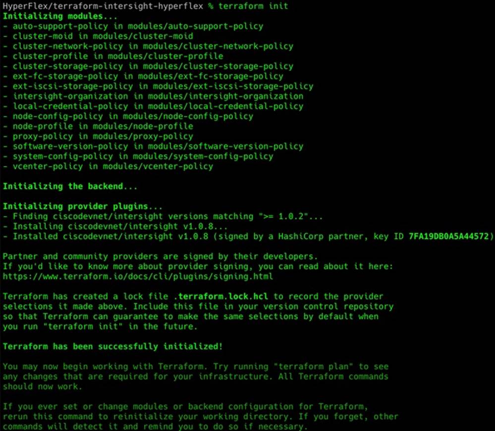
The plan command is used to evaluate the Terraform script for any syntax errors or other problems. The script will be evaluated against the existing environment and a list of planned actions will be shown. If there are no errors and the planned actions appear correct, then it is safe to proceed to running the apply command in the next step. To evaluate the Terraform plan, via the CLI change to the terraform-intersight-hyperflex folder where the GitHub repository was cloned, then run:
terraform plan
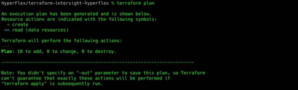
![]() To run the Terraform plan against a specific variable file, use the switch -var-file=. For example, terraform plan -var-file=cluster1.tfvars
To run the Terraform plan against a specific variable file, use the switch -var-file=. For example, terraform plan -var-file=cluster1.tfvars
The final step is to apply the new configuration. This command will repeat the planning phase and then ask for confirmation to continue with creating the new resources. To run the Terraform plan, via the CLI change to the terraform-intersight-hyperflex folder where the GitHub repository was cloned, then run:
terraform apply
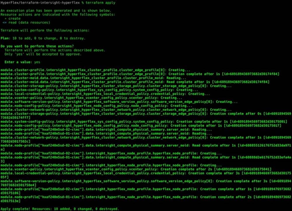
![]() To run the Terraform plan against a specific variable file, use the switch -var-file=. For example, terraform plan -var-file=cluster1.tfvars
To run the Terraform plan against a specific variable file, use the switch -var-file=. For example, terraform plan -var-file=cluster1.tfvars
![]() At the time of this document's publication, using the command "terraform destroy" will not properly delete Cisco HyperFlex resources. If the policies and profiles in Cisco Intersight need to be removed, they must be removed manually. If you wish to redeploy them using Terraform, the terraform.tfstate file must be edited or deleted to reset the Terraform environment, so that Terraform no longer thinks the Intersight resources still exist.
At the time of this document's publication, using the command "terraform destroy" will not properly delete Cisco HyperFlex resources. If the policies and profiles in Cisco Intersight need to be removed, they must be removed manually. If you wish to redeploy them using Terraform, the terraform.tfstate file must be edited or deleted to reset the Terraform environment, so that Terraform no longer thinks the Intersight resources still exist.
The Terraform script will create all of the required policies and the Cisco HyperFlex Edge cluster profile; however it will not trigger a validation or deployment task. Starting a validation or deployment job must be completed using the Cisco Intersight web GUI. If multiple clusters are being deployed using Terraform, the scripts for each cluster can be run first, so that all of the resulting clusters can be deployed via Cisco Intersight simultaneously. To begin the deployment of the Cisco HyperFlex Edge clusters which were configured via Terraform, follow these steps:
1. Using a supported web browser, log in to Cisco Intersight at https://www.intersight.com.
2. On the left-hand side menu, click Profiles.
3. Click the name of the Cisco HyperFlex Edge cluster which you wish to begin deploying.
4. Click Update or Next of the first four screens without changing any values or settings.
5. In the Summary screen, click Validate & Deploy.
6. Observe the status of the deployment job until it is completed. Installation time will vary based on network bandwidth, but typically takes about 1-2 hours. You can remain on the results page to watch cluster deployment progress in real time. Alternatively, you may click Close to send the task into the background and navigate elsewhere within Intersight. To return to this results view, navigate back to the CONFIGURE > Policies > HyperFlex Cluster Profile list view and select the cluster name.
7. Repeat steps 1-6 for each cluster to be deployed.
Post-installation Tasks and Testing
After the initial installation of the new Cisco HyperFlex Edge cluster is complete, the cluster is operational, yet several additional tasks must be completed in order to begin hosting virtual workloads. Post-installation tasks include running the post-installation script, creating datastores, configuring licensing, and performing initial testing and validation work.
Post-installation Script
Prior to putting a new HyperFlex Edge cluster into production, a few post-install tasks must be completed. To automate several of the post installation procedures and verify the HyperFlex Edge cluster configuration, a post_install script has been provided on the HyperFlex Controller VMs. This script will configure the settings of the ESXi cluster, create guest VM port groups, configure vMotion, and run a cluster health check. To run this script, follow these steps:
1. SSH to the cluster management IP address and login using "admin" as the username and the controller VM password provided during installation. Verify the cluster is online and healthy using "hxcli cluster info."
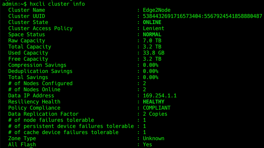
2. Run the following command in the shell, and press enter:
hx_post_install
3. Select the first post_install workflow type – New/Existing Cluster.
4. Enter the HX Storage Controller VM root password for the HX cluster (use the one entered during the HX Cluster installation).
5. Enter the vCenter server username and password.
6. Enter the ESXi host root password (use the one entered during the HX Cluster installation).
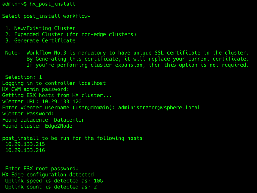
7. Enter "y" if you wish to enter licensing keys for the ESXi hosts via the script. Enter "n" if you wish to enter and manage the license information in vCenter.
8. Enter "y" to enable HA/DRS if you have the appropriate licensing to enable these features.
9. Enter "y" to disable the ESXi hosts’ SSH warning.
10. Add the vMotion VMkernel interfaces to each node by entering "y" if desired. Input the netmask, the vMotion VLAN ID, plus a starting and ending vMotion IP address range to be used by the hosts. The script will assign the addresses in sequential order.
11. Enter "y" to create one or more port groups for the guest VMs. Enter the name(s) for the additional port groups and VLAN IDs. The VM network portgroups will be created and added to the vm-network vSwitch. This step will add identical network configurations to all the nodes in the cluster.
12. Enter "y" to run the health check on the cluster.
13. A summary of the cluster will be displayed upon completion of the script. Make sure the cluster is healthy.
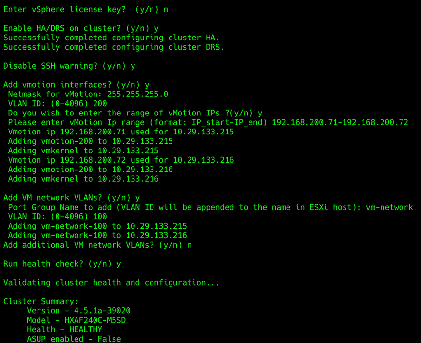
![]() When using Cisco ACI VMM integration, the portion of the Cisco HyperFlex post_install script which prompts to add port groups for the guest VMs should be skipped. If VMM integration is to be used for vMotion, that portion of the post_install script should be skipped as well.
When using Cisco ACI VMM integration, the portion of the Cisco HyperFlex post_install script which prompts to add port groups for the guest VMs should be skipped. If VMM integration is to be used for vMotion, that portion of the post_install script should be skipped as well.
Local Witness for 2-node Clusters
Cisco HyperFlex Edge clusters can be installed in a wide variety of locations, due to their small footprint and flexibility of performance and storage capacity. Because of their self-contained nature, many Edge systems are being deployed in locations which have a need for significant IT support but were previously underserved, such as offshore oil rigs, mining facilities, cargo ships, and other remote sites. Many of these locations can suffer from intermittent connectivity to the internet. At the same time, keeping the overall number of devices as low as possible is vital, in order to reduce costs and to minimize space and power consumption. In such an environment, a 2-node Cisco HyperFlex Edge cluster is a great fit, but the normal mode of operation for 2-node clusters uses the Cisco Intersight-based invisible cloud witness service to form a quorum for the cluster. In an environment where internet connectivity may be sporadic, the risk of cluster failure is heightened if a node were to fail while the invisible cloud witness service was not available due to lack of internet connectivity.
To overcome this risk, Cisco has partnered with Schneider Electric, makers of the APC line of uninterruptible power supplies (UPS). In partnership with Cisco, Schneider Electric has added a feature to their APC UPS Network Management Card (NMC) model 3 to run the Cisco HyperFlex witness service on the NMC itself. A compact Cisco HyperFlex Edge deployment can consist of 2 HX-series nodes, plus an APC UPS, all in a 4 RU side mount wall cabinet, taking up minimal space but providing significant IT resources to the end-users and other on-site systems. The NMC in the APC UPS runs the witness service, eliminating the need for continuous internet connectivity from the Cisco HyperFlex Edge cluster, while maintaining full redundancy at all times. In addition, APC PowerChute can optionally be installed and configured to automatically handle graceful shutdown of the guest VMs and the HyperFlex cluster itself when power outages occur.
To transition to using the embedded local witness, a 2-node Cisco HyperFlex Edge cluster must first be installed normally via Cisco Intersight, which will by default use the invisible cloud witness. The NMC model 3 card must have firmware version 1.4 or later, and the witness service must be enabled by downloading the config.ini file from the NMC via the web GUI, FTP or SCP, modifying the file and then uploading the modified file back to the NMC. Details of the INI file download and upload process can be found here: https://www.apc.com/us/en/faqs/FA156117/
The INI file must be modified to include the following section:
[HyperFlex]
Access=enabled
Username=<username>
Password=<password>
The username and password for the witness service are unique and independent from the account and password which manages the NMC. Additional testing and verification of the witness service can be done, the details of which are available here: https://download.schneider-electric.com/files?p_enDocType=Application+solutions&p_File_Name=AN_NMC_Local_Witness_for_Cisco_Hyperflex_R5.pdf&p_Doc_Ref=SPD_AN_NMC_HX_LWIT
Once the NMC has been configured and tested, the Cisco HyperFlex Edge cluster can be modified to use the local witness instead of the cloud witness. To change the 2-node cluster witness service, follow these steps:
1. Use a web browser to open HyperFlex Connect at the HX cluster management IP address.
2. Enter a local credential, or a vCenter RBAC credential with administrative rights for the username, and the corresponding password.
3. Click Login.
4. Click the gear icon in the upper right-hand corner, then click Device Connector.
5. Click the Settings link in the upper right-hand corner of the Device Connector window.
6. Click HyperFlex Witness on the left-hand side, then click External Witness.
7. Enter the URL of the NMC which will act as the witness for this cluster. The URL can be an IP address or a fully qualified name if it listed in DNS. For example, https://10.94.145.5/hyperflex or https://dc01-nmc04/hyperflex
8. Enter the username and password configured for the witness service on the NMC via the INI file.
9. Click Save.
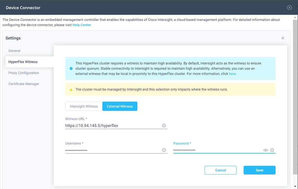
HyperFlex 2.5 and later utilizes Cisco Smart Licensing, which communicates with a Cisco Smart Account to validate and check out HyperFlex licenses to the nodes, from the pool of available licenses in the account. At the beginning, Smart Licensing is enabled but the HX storage cluster is unregistered and in a 90-day evaluation period or EVAL MODE. For the HX storage cluster to start reporting license consumption, it must be registered with the Cisco Smart Software Manager (SSM) through a valid Cisco Smart Account. Before beginning, verify that you have a Cisco Smart account, and valid HyperFlex licenses are available to be checked out by your HX cluster.
To create a Smart Account, go to Cisco Software Central > Request a Smart Account https://webapps.cisco.com/software/company/smartaccounts/home?route=module/accountcreation .
To activate and configure smart licensing, follow these steps:
1. Navigate to Cisco Software Central (https://software.cisco.com/) and log in to your Smart Account.
2. In the License pane, click Smart Software Licensing to open Cisco Smart Software Manager.
3. Click Inventory, click General, and then click New Token.
4. In the Create Registration Token dialog box, add a short Description for the token, enter the number of days you want the token to be active and available to use on other products, and check Allow export-controlled functionality on the products registered with this token.
5. Click Create Token.
6. From the New ID Token row, click the Actions drop-down list, and click Copy.
7. Use a web browser to open HX Connect at the HX cluster management IP address.
8. Enter a local credential, or a vCenter RBAC credential with administrative rights for the username, and the corresponding password.
9. Click Login.
10. From the HyperFlex Connect webpage, on the main Dashboard page, click the link at the top for "Cluster License not registered".
11. Enter or paste the Registration Token copied from Cisco Smart Software Manager, then click Register.
12. Click System Information, at view the information at the top of the screen to confirm that your HX storage cluster is registered.
Cisco HyperFlex nodes can be configured to use Secure Boot Mode after the initial installation is completed. This optional configuration requires that all drivers and modules loaded by the node during boot are digitally signed and considered safe, preventing malicious code execution from happening during the system startup process. All nodes in a cluster must be configured to use Secure Boot Mode together, and the setting must be enabled using the HyperFlex Connect management page as an upgrade task. Attempting to manually configure secure boot via the CIMC of the HX-series servers can cause unexpected behavior and failures. The upgrade job will enable Secure Boot Mode on each server one-by-one and reboot them each in turn. Because of this behavior, the vCenter cluster must have DRS and vMotion enabled to automatically evacuate the VMs from each host as they are rebooted. Each node takes roughly 15 minutes to evacuate, reboot and for the cluster to return to a healthy state before the next reboot will proceed.
To enable Secure Boot, follow these steps:
1. Use a web browser to open HyperFlex Connect at the HX cluster management IP address.
2. Enter a local credential, or a vCenter RBAC credential with administrative rights for the username, and the corresponding password.
3. Click Login.
4. From the HyperFlex Connect webpage, click Upgrade.
5. Click Check Upgrade Eligibility.
6. Click Secure Boot Mode, then enter the CIMC IP addresses, usernames, and passwords, plus the vCenter username and password, then click Validate.
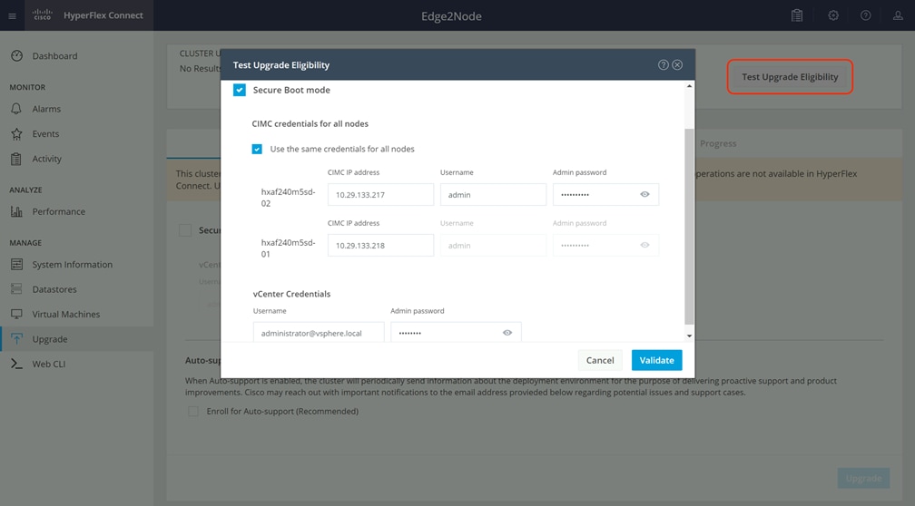
7. The test will take a few minutes to finish. After it is complete, view the results of the eligibility test at the top of the page.
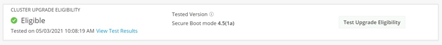
8. If the test successfully confirms the eligibility of the cluster to use Secure Boot Mode, then continue by checking the box for Secure Boot Mode, then enter the CIMC IP addresses, usernames, and passwords, plus the vCenter username and password, then click Upgrade.
9. Observe the status of the upgrade job as the nodes are reconfigured and rebooted.
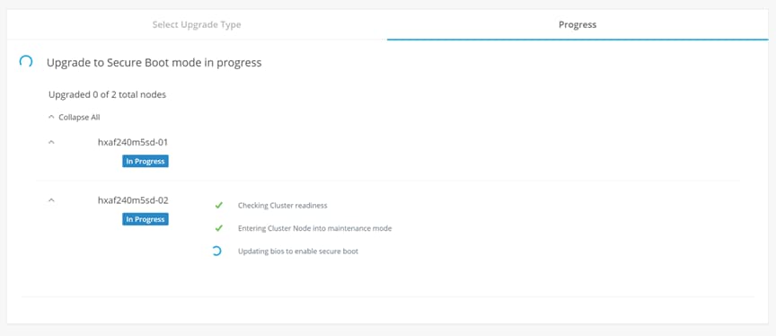
10. After the upgrade job completes, the Secure Boot Mode status can be confirmed in the System Information page. Click System Information, then from the Actions menu click Check Secure Boot Status.
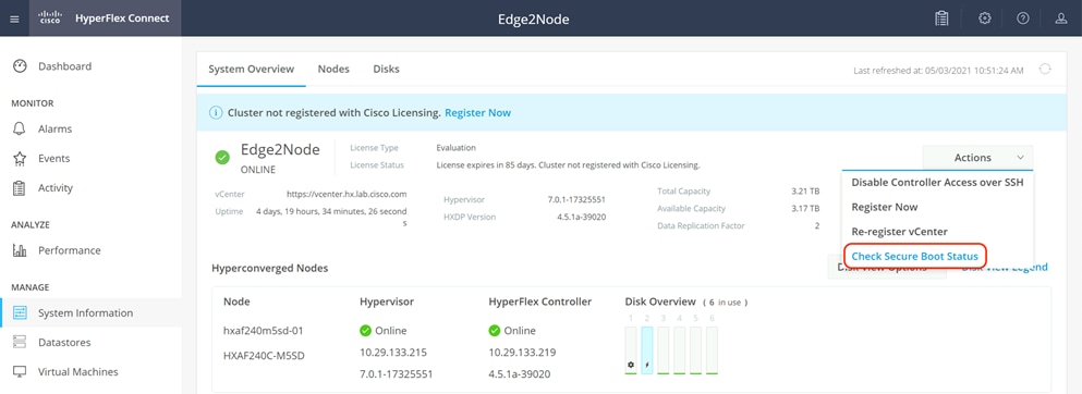
By default, the HyperFlex controller VMs store logs locally for many functions, including the filesystem logs, security auditing, CLI commands and shell access, single sign-on logs, and more. These logs are rotated periodically and could be lost if there were a total failure of a controller VM. In order to store these logs externally from the HyperFlex cluster, audit logging can be enabled in HX Connect to send copies of these logs to an external syslog server. From this external location, logs can be monitored, generate alerts, and stored long term. HX Connect will not monitor the available disk space on the syslog destination, nor will it generate an alarm if the destination server is full. To enable audit logging, follow these steps:
1. Use a web browser to open HyperFlex Connect at the HX cluster management IP address.
2. From the HyperFlex Connect webpage, click the gear shaped icon in the upper right-hand corner, and click Audit Log Export Settings.
3. Click to check the box to Enable audit log export to an external syslog server.
4. Enter the syslog server IP address and TCP port.
5. Choose TCP or TLS as the connection type. If using TLS, client certificate and private key pair files must be provided. Alternatively, a self-signed certificate can be used. Click browse to select the appropriate files.
6. Click OK.
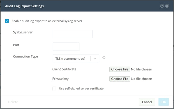
![]() Audit log exports can be temporarily disabled or completely deleted at a later time from the same location.
Audit log exports can be temporarily disabled or completely deleted at a later time from the same location.
To store ESXi diagnostic logs in a central location if they are needed to help diagnose a host failure, it is recommended to enable a syslog destination for permanent storage of the ESXi host logs for all Cisco HyperFlex hosts. It is possible to use the vCenter server as the log destination in this case, or another syslog receiver of your choice. Syslog settings can be changed via the vSphere HTML5 client webpage by editing the advanced system setting named "Syslog.global.LogHost". Alternatively, a faster method can be done via the CLI of the individual ESXi hosts as shown below.
To configure syslog for ESXi, follow these steps:
1. Log into the ESXi host via SSH as the root user.
2. Enter the following commands, replacing the IP address in the first command with the IP address of the vCenter server that will receive the syslog logs:
[root@hx220-01:~] esxcli system syslog config set --loghost='udp://10.29.133.120'
[root@hx220-01:~] esxcli system syslog reload
[root@hx220-01:~] esxcli network firewall ruleset set -r syslog -e true
[root@hx220-01:~] esxcli network firewall refresh
3. Repeat these steps for each ESXi host.
Auto-Support and Notifications
Auto-Support should be enabled for all clusters during the initial HyperFlex installation. Auto-Support enables Call Home to automatically send support information to Cisco TAC, and notifications of tickets to the email address specified. If the settings need to be modified, they can be changed in the HyperFlex Connect HTML management webpage.
A list of events that will automatically open a support ticket with Cisco TAC is as follows:
● Cluster Capacity Changed
● Cluster Unhealthy
● Cluster Health Critical
● Cluster Read Only
● Cluster Shutdown
● Space Warning
● Space Alert
● Space Critical
● Disk Blacklisted
● Infrastructure Component Critical
● Storage Timeout
To change Auto-Support settings, follow these steps:
1. From the HyperFlex Connect webpage, click the gear shaped icon in the upper right-hand corner, and click Auto-Support Settings.
2. Enable or disable Auto-Support as needed.
3. Enter the email address to receive alerts when Auto-Support events are generated.
4. Enter in the information for a web proxy if needed.
5. Click to accept the terms and conditions, which can be reviewed as needed.
6. Click OK.
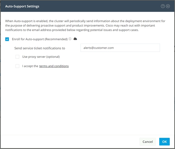
Alarms generated on the HyperFlex cluster can also be configured to create emails sent directly to a desired recipient. To enable direct email notifications, follow these steps:
1. From the HyperFlex Connect webpage, click the gear shaped icon in the upper right-hand corner, and click Notifications Settings.
2. Enter the DNS name or IP address of the outgoing email server or relay, the email address the notifications will come from, and the recipients.
3. Click OK.
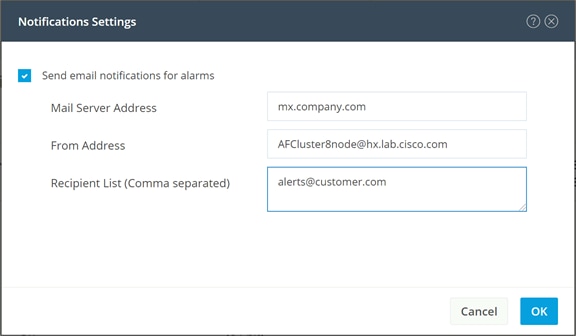
Create a datastore for storing the virtual machines. This task can be completed by using the HyperFlex Connect HTML management webpage. To configure a new datastore via the HyperFlex Connect webpage, follow these steps:
1. Use a web browser to open HyperFlex Connect at the HX cluster management IP address.
2. Enter a local credential, or a vCenter RBAC credential with administrative rights for the username, and the corresponding password.
3. Click Login.
4. Click Datastores in the left pane and click Create Datastore.
5. In the popup, enter the Datastore Name and size. For most applications, leave the Block Size at the default of 8K. Only dedicated Virtual Desktop Infrastructure (VDI) environments should choose the 4K Block Size option.
6. Click Create Datastore.
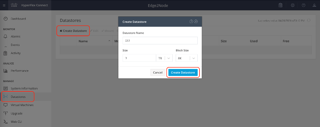
In order to perform initial testing and learn about the features in the HyperFlex cluster, create a test virtual machine stored on your new HX datastore in order to take a snapshot and perform a cloning operation.
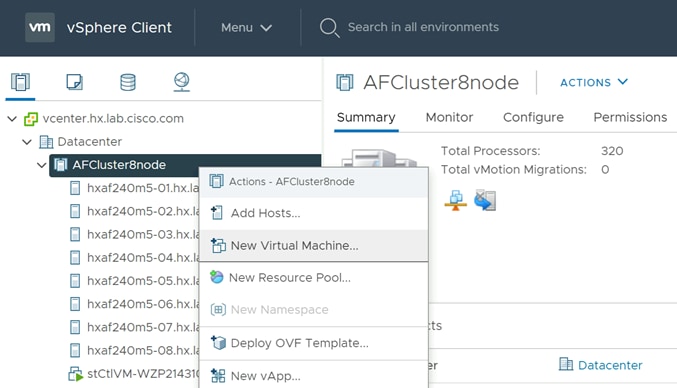
Take a snapshot of the new virtual machine prior to powering it on. Creating the first snapshot via the HyperFlex Connect webpage creates a HyperFlex native snapshot, which is faster and more space efficient then standard VMware snapshots. Creating the first snapshot via the vCenter snapshot manager will not create an HX native snapshot. When using HX native snapshots, a snapshot named "SENTINEL" will exist as the underlying root native snapshot, and all other snaps taken will be based on that. The SENTINEL snapshot should not be reverted to nor deleted unless all snapshots for that VM are being purged. Once an initial snapshot is created as an HX native snapshot via HyperFlex Connect, subsequent snapshots can be taken via the vCenter snapshot manager, and they will be HX native snapshots as well.
To take an instant HyperFlex native snapshot of one or more VMs, follow these steps:
1. In the HyperFlex Connect webpage, click the Virtual Machines menu, click to check the box next to the name(s) of the VM(s) to snapshot, then click Snapshot Now.
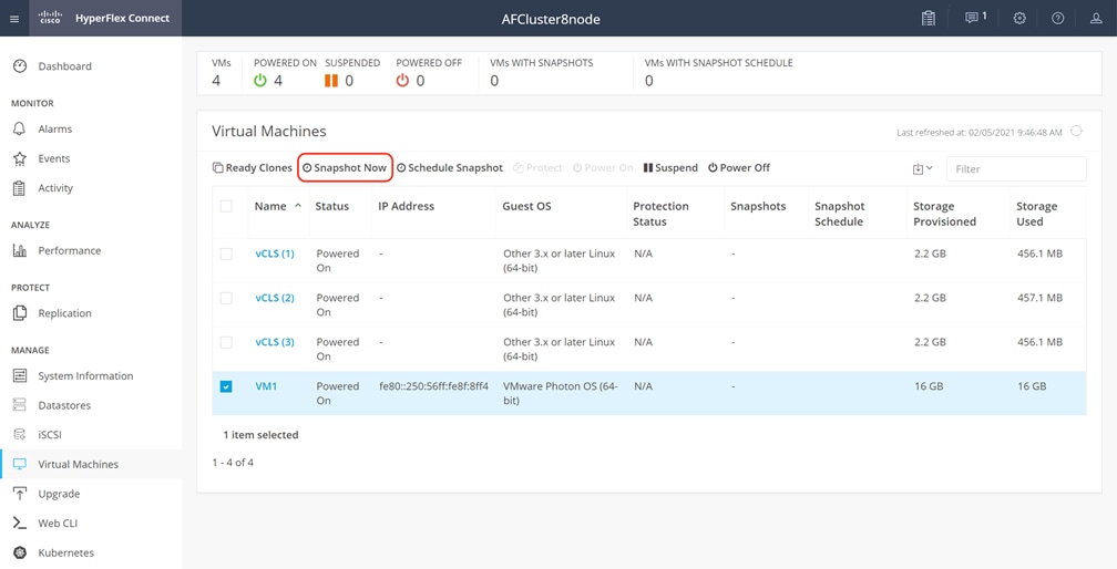
2. Input the snapshot name, a description if desired, and choose whether to quiesce the VM, then click Snapshot Now.
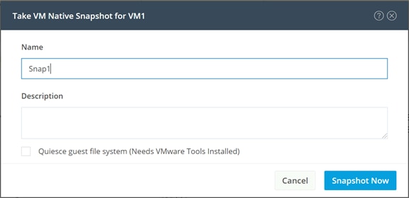
HyperFlex connect allows for the creation of scheduled snapshots of VMs at hourly, daily and/or weekly intervals. Scheduled snapshots also have a defined retention period so that older snaps will be automatically aged out of the system. In this way, scheduled snapshots can provide another layer of protection of your VMs by keeping a rolling number of hourly, daily, and weekly snapshots to revert back to in case of any data, application, or OS level problems.
To schedule HyperFlex native snapshots of one or more VMs, follow these steps:
1. In the HyperFlex Connect webpage, click the Virtual Machines menu, click to check the box next to the name(s) of the VM(s) to snapshot, then click Schedule Snapshot.
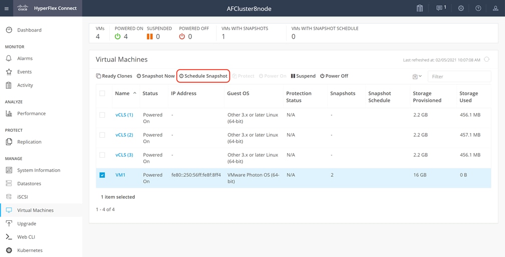
2. Select the options desired for the snapshot schedule. Snapshots can be selected to occur automatically once per hour, once per day, and/or once per week. Select the times for the snapshots, the days of the week for them to be taken, along with the number of snapshots to retain. For example, this configuration would be useful for a high importance or business critical VM, because it is configured with hourly snapshots for 12 hours per day, plus daily snapshots retained for a week, then weekly snapshots retained for 4 weeks.
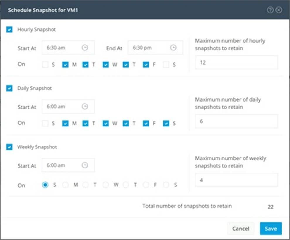
Cisco HyperFlex can create nearly instant clones of existing VMs directly via the HXDP filesystem. In the next test you will create a few clones of the test virtual machine.
To create the Ready Clones, follow these steps:
1. In the HyperFlex Connect webpage, click the Virtual Machines menu, click the checkbox to select the VM to clone, then click Ready Clones.
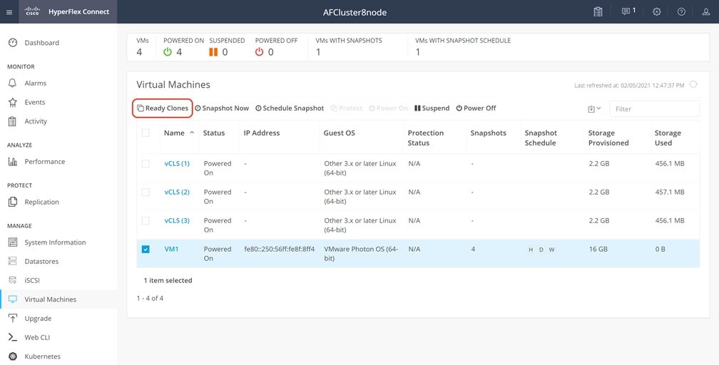
2. Input the Number of clones to create, a customization specification if needed, a resource pool if needed, and a naming prefix, then click Clone to start the operation. The clones will be created in seconds.
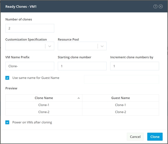
The cluster is now ready for use. You may run any other preproduction tests that you wish to run at this point, such as redundancy and failover validation, or performance benchmarking using HyperFlex Bench.
Cisco ACI Remote Leaf Networking
The increased adoption of Cisco Application Centric Infrastructure (Cisco ACI) networking fabrics has required Cisco ACI to adapt and conform to more widely used and varied architectures. Initially, Cisco ACI 1.0 designs consisted of a single data center network, with spine and leaf switches in a two-tier layout (a single Pod) controlled by a single Cisco Application Policy Infrastructure Controller (Cisco APIC) cluster. Cisco ACI 2.0 further extended this model for customers with multiple large and geographically dispersed data centers by enabling ACI Multipod designs, where each data center network Pod was physically separate, connected via externally routed IP networks (also known as an interpod network or IPN), but still managed as a single ACI fabric by a distributed Cisco APIC cluster. Cisco ACI 3.0 introduced ACI Multisite, which further split the management of multiple physical locations for fault isolation, by allowing each site to run its own Cisco APIC cluster but remain coordinated through the use of the Cisco ACI Multisite Orchestrator.
While these advances have addressed the needs of large data center networks, they did not meet the needs or desires for network administrators to extend the management and functionality of Cisco ACI to smaller locations or remote sites. Such smaller locations are often not a candidate to contain their own two-tier spine and leaf switch arrangement due to space, cost, and power concerns. Because of this, they cannot participate in a traditional Cisco ACI Multipod deployment. To address this, Cisco ACI 3.1 introduced a Remote Leaf solution that extended the fabric to such locations, allowing them to fall under the management of the larger Cisco ACI fabric without being a full-fledged ACI pod. The Remote Leaf solution offers significant operational value because it can manage multiple remote locations where Cisco HyperFlex Edge deployments would often be located, without investing in APIC controllers and spine switches at each remote location. Enterprises can leverage this architecture to support multiple remote data centers with HyperFlex Edge in each location. The number of remote leaf switches, and therefore the number of remote data center locations, that can be supported in a single ACI fabric for the different Cisco APIC releases can be found in the Verified Scalability Guides located here: https://www.cisco.com/c/en/us/support/cloud-systems-management/application-policy-infrastructure-controller-apic/tsd-products-support-series-home.html.
Key business values of the Remote Leaf solution include:
● Extension of the ACI policy model outside of the main data center to multiple remote sites, distributed over an IP interpod network (IPN) backbone.
● Extension of the ACI fabric to small data centers and remote locations without investing in a full sized ACI Fabric in each location.
● Centralized policy management and control plane for remote locations.
● Small form factor solutions at locations with cost, space and/or power constraints.
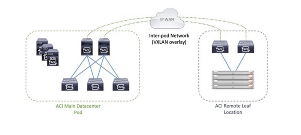
The Remote Leaf configuration becomes an ideal design for customers who have invested in deploying a Cisco ACI fabric and wish to extend the management and policies of ACI to the remote sites, where they will also be installing a Cisco HyperFlex Edge cluster. The deployment of the IP-based Interpod Network (IPN), which uses VXLAN as an overlay, is highly dependent on the various WAN technologies in use and varies significantly from customer to customer. As such, this paper will assume that architectural decisions have been previously made, and an IPN design is already in place, awaiting the deployment of new Remote Leaf switches in the remote locations.
For more information, refer to the ACI Remote Leaf Architecture White Paper here: https://www.cisco.com/c/en/us/solutions/collateral/data-center-virtualization/application-centric-infrastructure/white-paper-c11-740861.html
Several prerequisite steps are assumed to have been completed for the purposes of this paper, primary among them is that the IPN is already in place between the main ACI fabric and the new location with the Remote Leaf switches. Routable layer 3 IP networking between the two sites to enable remote leaf discovery and for establishing VXLAN overlays must be functional, with an MTU setting large enough to contain the additional overlay headers, and Dynamic Host Recovery Protocol (DHCP) relay to the Cisco APIC controllers for device discovery. The new Remote Leaf switches must be racked, cabled, and running a compatible version of Cisco ACI firmware, and not booting from a Cisco NX-OS firmware.
For more information and detailed instructions on the remote leaf configuration and setup, refer to the Cisco APIC Configuration Guide available here: https://www.cisco.com/c/en/us/td/docs/switches/datacenter/aci/apic/sw/4-x/L3-configuration/Cisco-APIC-Layer-3-Networking-Configuration-Guide-42x/Cisco-APIC-Layer-3-Networking-Configuration-Guide-42x_chapter_011011.html?referring_site=RE&pos=3&page=https://www.cisco.com/c/en/us/support/docs/cloud-systems-management/application-policy-infrastructure-controller-apic/213619-aci-remote-leaf-discovery-and-configurat.html
After the IPN configuration is completed, and the new Remote Leaf switches are initially brought online, the new switches should be visible in Cisco APIC as Devices Pending Registration. The new Remote Leaf switches are added to the ACI fabric using a Quick Start wizard in Cisco APIC. After the new switches are added, the ACI fabric policies and objects can be created and deployed to the new devices. Cisco ACI objects and policies, such as Endpoint Groups (EPGs), Bridge Domains (BDs) and Virtual Routing and Forwarding (VRF) are logically grouped into a construct called a Tenant. In this design, a dedicated Infrastructure tenant is used for all connectivity required to bring the HyperFlex Edge cluster online and operational in the remote data center. For Applications and Services hosted on the HyperFlex Edge cluster, additional tenants can be created as needed. In this example, Hashicorp Terraform is used to rapidly deploy the required ACI tenant to support a new installation of Cisco HyperFlex Edge at the new site with the new Remote Leaf switches. Once the new Cisco HyperFlex infrastructure tenant is deployed and healthy, then an installation of Cisco HyperFlex can proceed, either using Cisco Intersight or using Hashicorp Terraform, both as described earlier in this document. Lastly, after the installation of Cisco HyperFlex is completed, you can enable Virtual Machine Manager (VMM) integration between Cisco APIC and VMware vCenter, allowing APIC to create and manage VMware Distributed Virtual Switches (vDS) and the portgroups for the guest VMs and applications in the Cisco HyperFlex cluster.
When the physical installation of the new Remote Leaf switches is completed and once they are manageable via their OOB management interfaces, and they are connected to the IPN, the switches can be added to the ACI fabric. To add the new Remote Leaf switches, follow these steps:
1. Log in with administrative rights to the Cisco APIC instance managing the ACI fabric.
2. In the top menu, click Fabric, then from the left-hand tree click Fabric Membership, then click the tab labeled Nodes Pending Registration. If all previous steps have been successfully completed, the two new Remote Leaf switches should be visible as devices not yet registered to the ACI fabric.
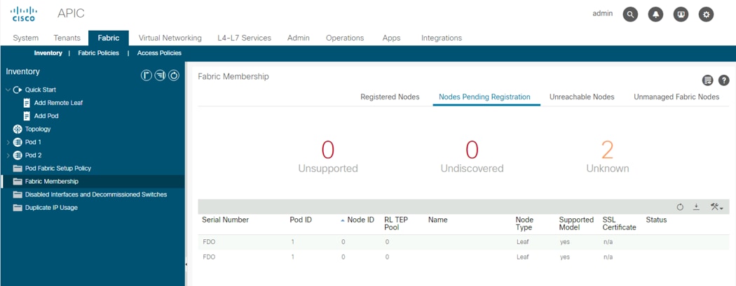
3. From the left-hand tree, click the carat next to Quick Start to expand the selection, click Add Remote Leaf, then click Add Remote Leaf to start the wizard.
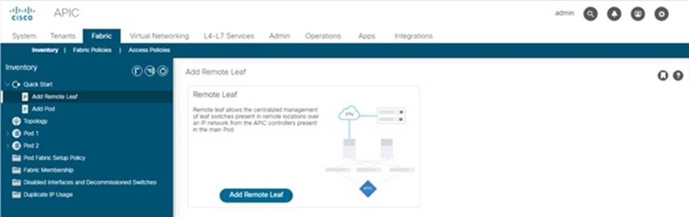
4. In Step 1, review the IPN information and prerequisites, then click Get Started.
5. In Step 2, select the ACI Pod ID to add the new devices to, enter a new TEP Pool for the Remote Leaf switches, then click Next.
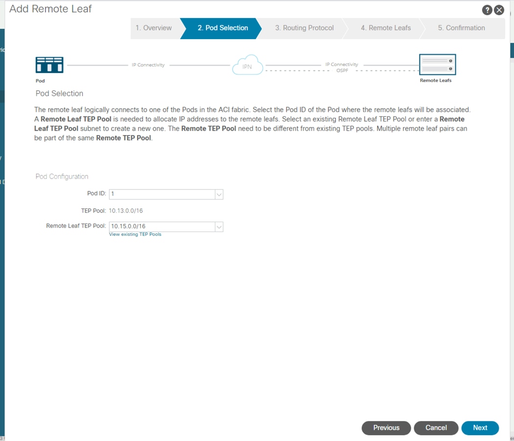
6. In step 3, enter or select the L3 Outside Configuration policy, enter the OSPF Area ID, Area Type, and select or configure a new OSPF Interface Policy, then click Next.
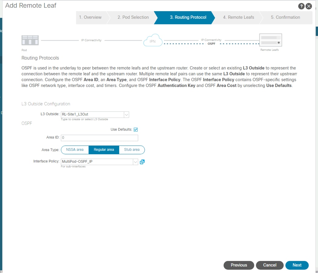
7. In step 4, select the first discovered Remote Leaf switch, enter a unique Node ID and name, enter the upstream router ID, and finally enter the Interface number, IP address and MTU of the interfaces facing the IPN. Additional interfaces can be added by clicking the + button. Click the + button at the far right to add more devices and enter the details of the second Remote Leaf switch, then click Next.
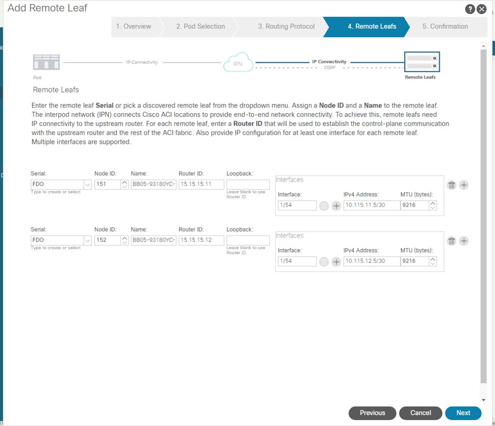
8. In step 5, review the list of policies that Cisco APIC will automatically create, then click Finish.
9. After the wizard completes, in the summary screen click OK.
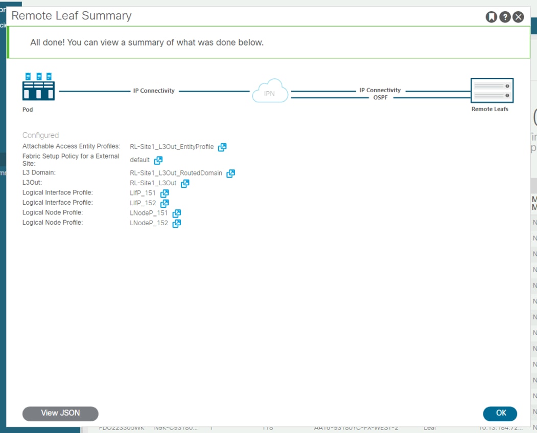
10. The new Remote Leaf switches will now be shown in the list of all registered nodes as Remote Leafs, and as leaf devices in the ACI pod they were added to.
APIC Configuration using Terraform
Terraform can be utilized with the Cisco ACI provider to communicate with Cisco APIC for the configuration of the ACI fabric and Remote Leaf switches. Using a scriptable tool such as Terraform, customers can more quickly implement more widespread deployments with fewer errors, because configurations are predefined in variables and the script files. This approach is often referred to as Infrastructure as Code (IaC). These scripts and configuration files can be created and validated prior to deployment and also retained in a version control system (VCS) repository for record keeping tracking configuration history.
Setup of the solution begins with a local management workstation that has access to Cisco APIC and with a working installation of Terraform. The management workstation commonly runs a variant of Linux or MacOS for ease of use with these command-line-based tools. Instructions for installing and configuring the workstation and Terraform are not included in this document. A guide for getting started with Hashicorp Terraform can be found at the following link: https://learn.hashicorp.com/terraform
To use the Terraform scripts demonstrated in this document, the management workstation must also have a working installation of Git and access to the Cisco UCS Compute Solutions public GitHub repository, using the HyperFlex-ACI-Projects collection. The Terraform scripts used in this document are cloned from the public repository, located at the following link: https://github.com/ucs-compute-solutions/HyperFlex-ACI-Projects
Alternatively, the example scripts can be modified and copied to a GitHub repository which is then linked with a Terraform Cloud workspace. The plans would then be executed via Terraform Cloud, which is configured to run plans on a Cisco IST agent, as opposed to the examples contained here, which show the plan execution from a local workstation.
The first step in the process is to clone the GitHub collection named "HyperFlex-ACI-Projects" to a new empty folder on the management workstation. Cloning the collection creates a local copy, which is then used to run the playbooks that have been created for this solution. To clone the GitHub collection, follow these steps:
1. From the management workstation, create a new folder for the project. The GitHub collection will be cloned in a new folder inside this one, named HyperFlex-ACI-Projects.
2. Open a command-line or console interface on the management workstation and change directories to the new folder just created.
3. Clone the GitHub collection using the following command:
git clone https://github.com/ucs-compute-solutions/HyperFlex-ACI-Projects
4. Change directories to the new folder named HyperFlex-ACI-Projects.
The collection contains two Terraform plans in the folder named HX-Edge-ACI-RemoteLeaf. The first, named "HXVe-ACI-1-FabrAccPolCfg.tf" creates many of the objects, pools and policies necessary to connect new Remote Leaf switches and prepare them for the new ACI tenant. The second, named "HXVe-ACI-2-InfraTenantCfg.tf" creates the base HyperFlex infrastructure tenant in Cisco APIC to support a new installation of a Cisco HyperFlex Edge cluster connected to the new ACI Remote Leaf switches. When working with a new environment, or a so called "greenfield" deployment, both plans must run in order to create all of the required objects, pools and policies. Terraform uses variables like many other scripting tools and languages in order to set temporary values for each run of the script. The variables are defined in the file named variables.tf, and their values are set in the file named variables.auto.tfvars. For each Cisco ACI Remote Leaf site to be created, supporting a Cisco HyperFlex Edge cluster, the included variables.auto.tfvars file can be modified, or a copy can be made with a unique name and referenced with each run of the script.
A description is provided below for each of the variables in the variables.auto.tfvars file included in the GitHub repository. The values should be modified as appropriate for the Remote Leaf switches being installed in your environment, and the ACI tenant being deployed.
● hxv_e_infra_ib_mgmt_vlan_id: Enter the HyperFlex in-band management VLAN ID.
● hxv_e_infra_vmotion_vlan_id: Enter the HyperFlex vMotion VLAN ID.
● hxv_e_infra_stordata_cl0_vlan_id: Enter the HyperFlex storage VLAN ID.
● hxv_e_phy_domain_name: Enter the name of the Cisco ACI physical domain to be created.
● hxv_e_aaep_name: Enter the name of the Attachable Access Entity Profile to be created and associated to the Cisco ACI physical domain.
● hxv_e_leaf_ipg_name: Enter the name of the Interface Policy Group for the HyperFlex Edge nodes to be created.
● hxv_e_leaf_ipr_name: Enter the name of the Interface Profile for the Remote Leaf switch interfaces.
● hxv_e_leaf_port_selector_name: Enter the name of the Cisco ACI leaf port selector to be created.
● hxv_e_from_module: Enter the starting module number of the Remote Leaf switch(es) being deployed.
● hxv_e_from_port: Enter the starting port number of the Remote Leaf switch(es) being deployed.
● hxv_e_to_module: Enter the ending module number of the Remote Leaf switch(es) being deployed.
● hxv_e_to_port: Enter the ending port number of the Remote Leaf switch(es) being deployed.
● hxv_e_leaf_spr_name: Enter the name of the Cisco ACI switch profile to be created.
● hxv_e_leaf_switch_selector_name: Enter the name of the Cisco ACI switch selector to be created.
● hxv_e_leaf_1_node_id: Enter the node ID of the first Cisco ACI Remote Leaf switch being configured.
● hxv_e_leaf_2_node_id: Enter the node ID of the second Cisco ACI Remote Leaf switch being configured.
● hxv_e_leaf_ports: Enter a list of the Remote Leaf ports being enabled for the Cisco HyperFlex Edge cluster in the following format: ["eth1/1","eth1/2","eth1/3","eth1/4"]
● hxv_e_infra_tenant_name: Enter the name of the new Cisco HyperFlex Edge infrastructure tenant being created.
● hxv_e_infra_vrf_name: Enter the name of the Cisco ACI VRF created to support the Cisco HyperFlex Edge cluster.
● hxv_e_infra_mgmt_bd_name: Enter the name of the Cisco HyperFlex Edge management bridge domain being created.
● hxv_e_infra_vmotion_bd_name: Enter the name of the Cisco HyperFlex Edge vMotion bridge domain being created.
● hxv_e_infra_stordata_cl0_bd_name: Enter the name of the Cisco HyperFlex Edge storage bridge domain being created. Every HX Edge cluster should be in a unique storage data BD.
● hxv_e_ib_mgmt_bd_subnet_ip: Enter the subnet for the Cisco HyperFlex Edge cluster in-band management network.
● hxv_e_infra_mgmt_ap_name: Enter the name of the Cisco ACI application profile created for the Cisco HyperFlex Edge management traffic.
● hxv_e_infra_vmotion_ap_name: Enter the name of the Cisco ACI application profile created for the Cisco HyperFlex Edge vMotion traffic.
● hxv_e_infra_stordata_ap_name: Enter the name of the Cisco ACI application profile created for the Cisco HyperFlex Edge storage data traffic.
● hxv_e_infra_mgmt_epg_name: Enter the name of the Cisco ACI Endpoint Group created for the Cisco HyperFlex Edge management endpoints.
● hxv_e_infra_vmotion_epg_name: Enter the name of the Cisco ACI Endpoint Group created for the Cisco HyperFlex Edge management traffic endpoints.
● hxv_e_infra_stordata-cl0_epg_name: Enter the name of the Cisco ACI Endpoint Group created for the Cisco HyperFlex Edge storage data traffic endpoints.
● hxv_e_l3out: Enter the name of the existing Layer-3 outbound policy for connectivity to the ACI fabric, using the following format:
{
tenant_name = "common"
name = "SharedL3Out-West-Pod1_RO"
contract = "Allow-Shared-L3Out"
}
To create the required variable file(s), follow these steps:
1. Using either the command line or a graphical file editor, modify the existing variables.auto.tfvars file with the values for the necessary variables to configure the ACI fabric to support the Cisco HyperFlex Edge cluster to be installed.
2. If using multiple files, then using either the command line or a graphical file editor, modify the new individual *.tfvars files with the values for the necessary variables to configure the ACI fabric to support the Cisco HyperFlex Edge cluster to be installed.
Terraform Init
The init command is used to initialize the Terraform environment for the script being run. Any additional provider modules, such as the Cisco ACI provider, are downloaded and all prerequisites are checked. This initialization only needs to be run once per script, and subsequent runs only need to execute plan and apply. To initialize the environment, via the CLI change to the HyperFlex-ACI-Projects folder where the GitHub repository was cloned, then run:
terraform init
The plan command is used to evaluate the Terraform script for any syntax errors or other problems. The script will be evaluated against the existing environment and a list of planned actions will be shown. If there are no errors and the planned actions appear correct, then it is safe to proceed to running the apply command in the next step. To evaluate the Terraform plan, via the CLI change to the HyperFlex-ACI-Projects folder where the GitHub repository was cloned, then run:
terraform plan HXVe-ACI-1-FabrAccPolCfg.tf
terraform plan HXVe-ACI-2-InfraTenantCfg.tf
The final step is to apply the new configuration. This command will repeat the planning phase and then ask for confirmation to continue with creating the new resources. To run the Terraform plan, via the CLI change to the HyperFlex-ACI-Projects folder where the GitHub repository was cloned, then run:
terraform apply HXVe-ACI-1-FabrAccPolCfg.tf
terraform apply HXVe-ACI-2-InfraTenantCfg.tf
Because the configuration of the ACI tenant is divided into two scripts, terraform plan and terraform apply must be run a second time using the HXVe-ACI-2-InfraTenantCfg.tf script as the source script.
After the deployment of the ACI tenant, monitor the status of the tenant via Cisco APIC. It may take several minutes for the settings to propagate and for the tenant to be marked as fully healthy.
Cisco ACI fabrics manage congestion on links using a single set of Quality of Service (QoS) levels which traffic can be mapped onto. Each of the six levels can be given a bandwidth allocation in order to define a relative weight to that traffic as compared to the other levels. The Cisco Github repository offers an example Terraform plan, named "HXVe-ACI-3-QoSCfg.tf", which would modify the existing Cisco ACI QoS level bandwidth allocations. This script is offered as an example of what is possible to achieve using Terraform, and not required to be run in order to configure new Cisco ACI Remote Leaf switches. In fact, if the Cisco ACI fabric has already been configured with specific QoS level settings and QoS traffic mappings, then this Terraform plan should be avoided and not run, as it would modify the single QoS level settings for the entire Cisco ACI fabric.
For the Cisco HyperFlex Edge deployment demonstrated in this document, the Terraform plan, named "HXVe-ACI-2- InfraTenantCfg.tf", which creates the Cisco ACI Endpoint Group for HyperFlex storage traffic, sets the QoS priority of that traffic to QoS level 1. Typically, level 1 would be configured to support the highest priority traffic in the fabric, and it is recommended that if QoS is employed, Cisco HyperFlex storage traffic would be classified as the highest priority traffic. This setting in the Terraform script can be modified if a different QoS level has a higher bandwidth allocation, if necessary. If QoS is not in use in your Cisco ACI fabric, the setting can be removed or commented out to leave the traffic in the default best-effort category.
One final consideration with respect to Cisco ACI QoS is the use of QoS on the VXLAN IP interpod network (IPN) connecting the main site and the site with the Remote Leaf switches. In our example configuration, the remote site contains two Remote Leaf switches, and each Cisco HyperFlex Edge node is connected to both of them. Normal traffic flow is dictated by the failover order defined in the VMware ESXi virtual switch configuration, which places all node-to-node storage traffic on the "B side" of the network, or in other words all via switch #2. There is a failure scenario when one node's connection to the "B side" switch fails, which results in storage traffic needing to traverse east/west between the "B side" Remote Leaf to the "A side" Remote Leaf. Because a two switch Remote Leaf deployment does not use traditional virtual port-channels (vPC) to directly connect to two switches to each other, this east/west traffic must be switched by the upstream IPN router, as illustrated in the following diagram. If such a failure were to occur, and if there was a large amount of traffic on the links connecting the two Remote Leaf switches to their upstream IPN router, then some node-to-node storage traffic could be delayed, dropped, or need to be retransmitted, which can cause significant slowdowns of the Cisco HyperFlex cluster.
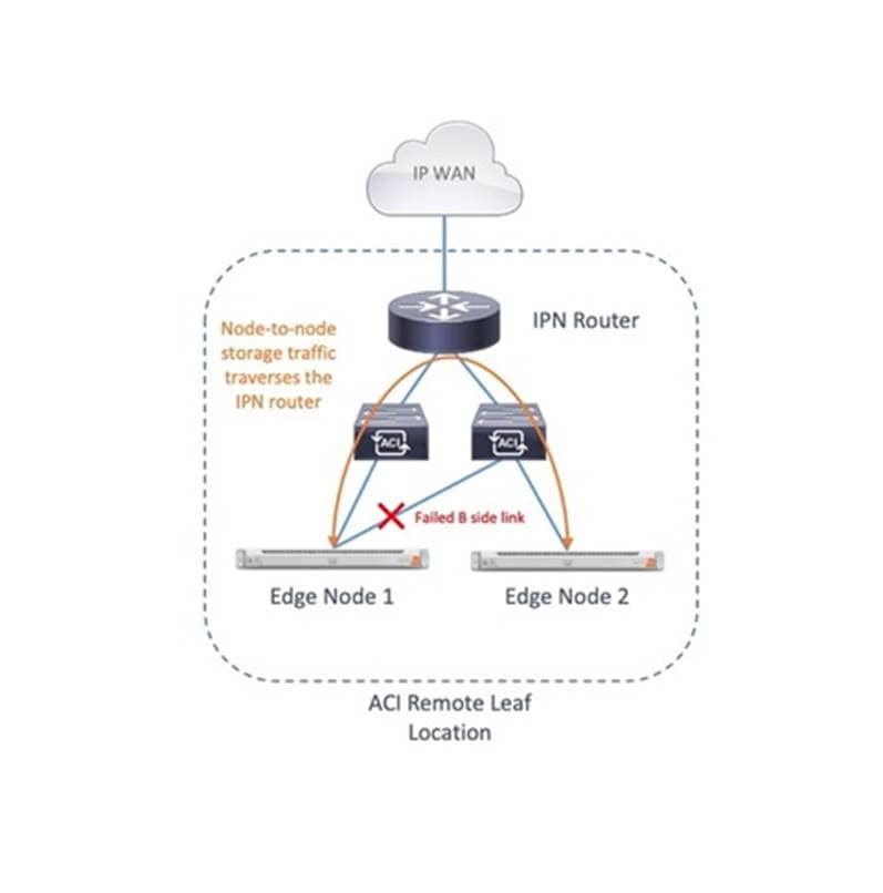
In order to mitigate this rare, but potential issue, a DSCP class-cos translation policy for L3 traffic must be implemented to prioritize storage traffic on the IPN router. Unfortunately, this feature also requires the Cisco ACI fabric to have the QoS Class of Service (COS) preservation setting disabled, which can impact other traffic in the fabric that relies on COS preservation. Any Cisco ACI fabric which will be implementing QoS needs careful attention, risk assessment and detailed planning to ensure that all workloads and traffic flows are classified and prioritized in the most effective manner. These QoS policy settings, descriptions of their resultant behavior and planning steps can become highly complicated and are beyond the scope of this paper. Additional details regarding DSCP class-cos translation policies are available in the ACI Remote Leaf Architecture White Paper here: https://www.cisco.com/c/en/us/solutions/collateral/data-center-virtualization/application-centric-infrastructure/white-paper-c11-740861.html
Verify HX-series Server Connectivity
After the configuration of Cisco APIC, an important step before continuing with the Cisco HyperFlex installation is to verify that the HX-series rackmount servers have active physical links to the Remote Leaf switches. Cisco HX-series servers for HyperFlex Edge contain the Cisco VIC 1457, which is a 10Gb or 25Gb Ethernet host adapter. The choice of 10Gb or 25Gb in many cases depends upon which model of switches the nodes will be connected to. Many models of switches have ports that are also capable of 10Gb or 25Gb, therefore the determining factor for the resulting interface speed becomes which model of interconnect cable and transceiver is used. Cables designed for 10Gb and 25Gb Ethernet use different signaling and different types of Forwarding Error Correction (FEC). In many cases the interfaces should properly auto negotiate, but in some situations, particularly with 25Gb transceivers, the FEC settings on the upstream switches or the Cisco VIC may need to be manually set in order for the physical links to come online. For example, the Terraform script provided creates a Link Level Policy named "Nexus-YC-EX-25Gbps", which sets the speed to 25Gb using CL74-FC-FEC Forward Error Correction. This was done to lock the interfaces to use CL74-FC-FEC, which is the appropriate setting for the 3M 25Gb passive copper transceivers used in the lab environment. In addition, the FEC setting on the HX-series VICs had to be manually set to CL74 via the CIMC CLI.
The link status can be confirmed via the HX-series servers' CIMC, from the Networking menu click Adapter Card MLOM, then click the External Ethernet Interfaces tab. Verify the two connected ports show a link state of "Link Up" before continuing, as shown below.
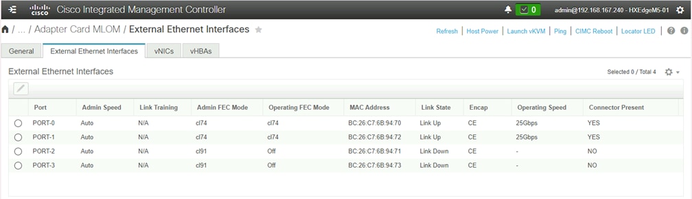
If the link state remains as "Link Down" after the deployment of the ACI tenant, then the FEC settings of the ACI Link Level policy may need to be modified, as well as modified in the CLI of the CIMC of the HX-series servers. For 25Gb connections, it is vital that the FEC mode of the interfaces on the switches and VICs match, and are the correct modes supported by the transceivers. Do not continue with the installation of Cisco HyperFlex until the two links per HX-series server are all shown as "Link Up."
If the FEC mode of the VIC cards must be modified on the HX-series servers' CIMC via the CLI, refer to the following instructions: https://www.cisco.com/c/en/us/td/docs/unified_computing/ucs/c/sw/cli/config/guide/4_0/b_Cisco_UCS_C-Series_CLI_Configuration_Guide_40/b_Cisco_UCS_C-Series_CLI_Configuration_Guide_40_chapter_01001.html
Additional information regarding Cisco ACI switches and their auto negotiation and Forward Error Correction settings and capabilities can be found here: https://www.cisco.com/c/en/us/td/docs/switches/datacenter/aci/apic/sw/kb/b_Cisco_ACI_and_Forward_Error_Correction.html
Additional information regarding Cisco 25Gb Ethernet transceivers, along with their supported FEC modes can be found here: https://www.cisco.com/c/en/us/products/collateral/interfaces-modules/transceiver-modules/datasheet-c78-736950.html
Once the Cisco APIC tenant for the Cisco HyperFlex infrastructure has been created via Terraform, and the physical interfaces of the HX-series servers have been verified to be online, installation of Cisco HyperFlex can proceed. Refer to the previous sections of this document beginning at Installation for details on the install process.
Enable Cisco ACI VMM Integration
A core feature of Cisco ACI is the ability to integrate management of virtual networking functions and configuration for VMware ESXi clusters into Cisco APIC. Cisco APIC can create managed Distributed Virtual Switches (vDS) in VMware vCenter, manage their settings and uplinks, plus create guest VM port groups as needed for the workloads running in the ESXi cluster. Because Cisco HyperFlex clusters utilize the VMware ESXi hypervisor, installations which also use Cisco ACI for the supporting network infrastructure can take advantage of the Virtual Machine Manager (VMM) integration features of Cisco ACI. ACI VMM integration is an optional feature and can be enabled using Cisco APIC along with VMware vCenter after the Cisco HyperFlex cluster has been installed. Conversion from the pre-installed standard ESXi virtual switches to vDS is supported for the guest VM networks and optionally for vMotion only. Enabling VMM integration requires that a pair of unused uplinks be available from each of the HX-series nodes, therefore if the conversion to vDS via VMM is desired for the guest VMs, the standard vSwitch named "vswitch-hx-vm-network" must first be deleted to free up its associated uplinks. Likewise, if the conversion to vDS via VMM is desired for vMotion traffic, the standard vSwitch named "vmotion" must first be deleted.
![]() When using Cisco ACI VMM integration, the portion of the Cisco HyperFlex post_install script which prompts to add port groups for the guest VMs should be skipped. If VMM integration is to be used for vMotion, that portion of the post_install script should be skipped as well.
When using Cisco ACI VMM integration, the portion of the Cisco HyperFlex post_install script which prompts to add port groups for the guest VMs should be skipped. If VMM integration is to be used for vMotion, that portion of the post_install script should be skipped as well.
Detailed documentation for the setup and management of VMM via Cisco APIC can be found online in the Cisco ACI Design guide located here: https://www.cisco.com/c/en/us/td/docs/dcn/whitepapers/cisco-application-centric-infrastructure-design-guide.html#VMMintegration
Additionally, integration steps are also described in the Cisco HyperFlex on ACI Multipod CVD located here: https://www.cisco.com/c/en/us/td/docs/unified_computing/ucs/UCS_CVDs/hx_40_vsi_aci_multipod.html#AddESXiHostsTovDS
While the previous documents outline the process to configure and use Cisco ACI VMM integration using the GUI based tools, the Cisco GitHub repository containing the ACI infrastructure tenant plans also contains example Terraform plans and additional variables which can be used to setup VMM integration via a script if desired. This configuration via Terraform is a multi-step process and is only included as an example of what is possible to achieve via Terraform and is not intended as a supported or recommended configuration method.
HyperFlex Edge N:1 Replication
Cisco HyperFlex 4.5 introduces a new feature for Edge cluster VM protection, called N:1 replication. Many remote locations do not have the space or infrastructure to properly backup and protect the VMs running in the site. Simply making copies of the VMs locally via snapshots is often inadequate as a backup strategy, as there is no viable restoration process if the local snapshots are lost or corrupted. IT administrators may want to further protect those VMs by replicating them to a central location, because remote sites can often have a larger risk of power fluctuations, fire, flooding or natural disasters, which negates the effectiveness of an on-site backup routine. Because HyperFlex Edge deployments are smaller footprint systems, a simple solution involves replicating the VMs from the Edge cluster to another HyperFlex cluster. Replication between HyperFlex clusters in a 1:1 relationship has been available since HXDP version 2.5, but this 1:1 limitation may not meet the needs of customers with numerous HyperFlex Edge deployments. N:1 replication allows a so-called "fan-in" design, where one larger centralized standard HyperFlex cluster, such as one using Cisco Fabric Interconnects, receives the backup data from multiple remote Edge clusters. The N:1 replication feature exists separately from the built-in native replication feature, and is entirely managed via Cisco Intersight, and not via HyperFlex Connect. A new, unique protected datastore is created, and snapshots of the protected VMs stored in that datastore are both held locally and replicated to the centralized cluster according to policy settings.
Prerequisites and Recommendations
The following requirements and recommendations must be considered when configuring N:1 replication for Cisco HyperFlex:
● All source and target systems must be running HXDP version 4.5(1a) or later.
● The feature is intended for HyperFlex Edge clusters as the source systems, and one standard FI-based HyperFlex cluster as the target.
● The source HyperFlex Edge clusters can be managed by the same vCenter system.
● The target HyperFlex cluster must be managed by a separate vCenter system than the one managing the source clusters.
● Intersight Essentials is required, and HyperFlex Edge Premier licensing is required for the HyperFlex Edge Clusters.
● Up to 20 Edge clusters replicating to a single FI-based cluster is supported, protecting up to 100 VMs per Edge cluster. The recommended configuration for a backup topology is 10 Edge clusters with 30 Virtual Machines per Edge cluster, replicating to one FI-based cluster.
● A dedicated replication VLAN must be configured and available on the upstream switches and WAN with a pingable gateway IP, and N+1 IP addresses are required per cluster, as outlined in the IP Addressing section.
● The MTU of the replication traffic must match across all locations.
● Clusters configured to participate in N:1 replication cannot also participate in standard native replication. Management and configuration should only be done via Cisco Intersight, and not via HyperFlex Connect.
All configuration of the N:1 replication feature is done via Cisco Intersight, except for ensuring the FI-based cluster has the appropriate replication VLAN set up in Cisco UCS Manager. From Cisco Intersight, the backup target cluster is first configured, then each source cluster is configured and finally the required backup policies can be created for the source clusters.
Target Replication Network Configuration
First, the replication network configuration for the target cluster must be completed via Cisco UCS Manager. To configure the replication network, follow these steps:
1. Using a supported web browser, log in to Cisco UCS Manager for the domain that manages the FI-based target HyperFlex cluster.
2. Click LAN from the navigation menu.
3. Under LAN Cloud, click VLANs.
4. Click Add, enter the VLAN name and VLAN ID for the replication VLAN.
5. Click OK.
6. In the navigation tree, click Policies > root > Sub-Organization > YOUR ORG NAME > vNIC Template > hx-mgmt-a.
7. Click Modify VLANs, click to check the replication VLAN which was just created, then click OK.
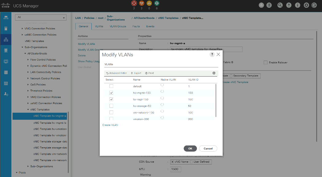
![]() Even if all the clusters will replicate using a single layer-2 subnet, the gateway address is required and must be pingable, as this will be tested during the configuration of the replication networking and policies.
Even if all the clusters will replicate using a single layer-2 subnet, the gateway address is required and must be pingable, as this will be tested during the configuration of the replication networking and policies.
After the replication VLAN is configured in Cisco UCS Manager, the target cluster can be configured. The N:1 target cluster must be previously installed, either using Cisco Intersight, or using the on-premises installer and subsequently imported into Cisco Intersight. To configure the target cluster, follow these steps:
1. Using a supported web browser, log in to Cisco Intersight at https://www.intersight.com.
2. On the left-hand side menu, click OPERATE > HyperFlex Clusters.
3. From the list of clusters, click the ellipsis (…) at the end of the row for the target cluster, then click Configure Backup.
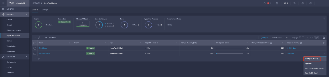
4. Expand the Replication Network Configuration section. Enter the replication VLAN ID, a bandwidth limit in Mbps, the replication network MTU, plus the starting and ending IP addresses for the replication network, the subnet mask and the replication network gateway.
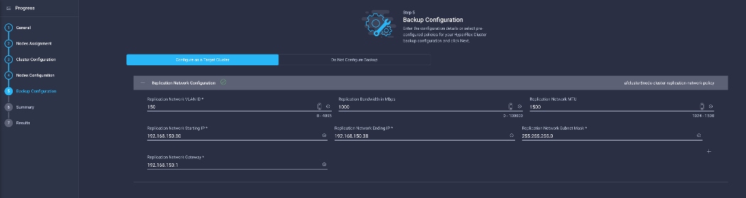
5. Click Next.
6. Click Validate & Deploy to begin the replication network configuration job. A list of configuration jobs will be shown with the newly submitted job at the top. Observe the status of the job, or alternatively click the job to view the details as it executes. Detailed information about the job status can also be seen in the HyperFlex connect Activity screen. The configuration typically completes within 5-10 minutes.
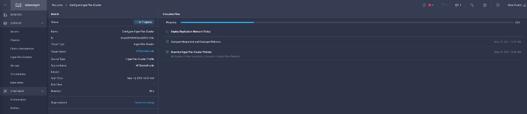
Once a target cluster is configured, the Edge cluster(s) can be configured with their replication network settings and backup policies. To configure the source cluster(s), follow these steps:
1. Using a supported web browser, log in to Cisco Intersight at https://www.intersight.com.
2. On the left-hand side menu, click OPERATE > HyperFlex Clusters.
3. From the list of clusters, click the ellipsis (…) at the end of the row for the source cluster, then click Configure Backup.
4. Expand the Replication Network Configuration section. Enter the replication VLAN ID, a bandwidth limit in Mbps, the replication network MTU, plus the starting and ending IP addresses for the replication network, the subnet mask and the replication network gateway.
5. Expand the Virtual Machine Backup Configuration section. Enter the replication time in minutes, and the number of snapshots to retain for the VMs.
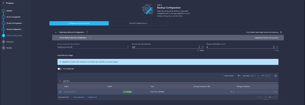
6. Select the target cluster to replicate the snapshots to, then click Next.
7. Click Validate & Deploy to begin the replication network configuration job. A list of configuration jobs will be shown with the newly submitted job at the top. Observe the status of the job, or alternatively click the job to view the details as it runs. Detailed information about the job status can also be seen in the HyperFlex connect Activity screen. The configuration typically completes within 5-10 minutes.
8. Repeat steps 3-7 for each additional Edge cluster which requires protection and replication of the VMs.
VMs will be automatically protected if they reside in the newly created datastore in the source cluster(s). The protected datastores have a prefix of "backup-source-ds_" followed by the last 8 digits of the cluster UUID. Creating or moving a VM in this datastore will enable automatic protection according to the policy settings set when replication was enabled. VMs that are moved out of the protected datastores will lose protection. If a VM resides in multiple datastores then they will not be protected. A similar datastore is created on the target cluster which is automatically managed and requires no end-user interaction.
Protected VMs can be restored via Cisco Intersight, either in the original cluster or in a different Edge cluster. When restoring to the original cluster, the restored VM can use the original name, or it can be restored with a new name. If the original VM still exists, it will be powered off and rolled back to the specified snapshot, then powered back on. If the original VM has been deleted then it will be recreated. Restorations to a different cluster must use a new specified name. Recovered VMs in the original Edge cluster will be placed into the protected datastore, so the restored VM will be automatically protected just as the original VM was. To restore a VM, follow these steps:
1. Using a supported web browser, log in to Cisco Intersight at https://www.intersight.com.
2. On the left-hand side menu, click OPERATE > HyperFlex Clusters, then click the Backups tab at the top.
3. Click Protected VMs, then from the list of protected VMs, click the ellipsis (…) at the end of the row for the VM to restore, and click Restore from Backup.
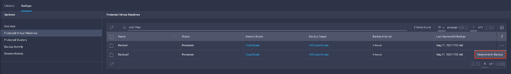
4. Select the snapshot to restore, then click Next.
5. Select the cluster to restore the VM to, then click Next.
6. Enter the desired name of the restored VM and the desired power state, then click Next.
7. Review the choices in the Summary screen, then click Restore.
8. Observe the status of the restore job on the Restore Activity screen until the job is completed.
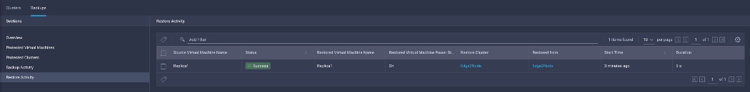
Moving a VM from a protected datastore or deleting a VM can leave behind the snapshot data in the source and target clusters, plus information retained in Cisco Intersight. To remove the snapshot data from the source and target clusters, and also from Cisco Intersight after a protected VM has been moved or deleted, a CLI command must be run. To remove the snapshot data, follow these steps:
1. Log in via SSH to the management IP address of the source HyperFlex Edge cluster, as user "admin" with the appropriate password.
2. From the command line, enter the command: stcli dp vm list --brief
admin:~$ stcli dp vm list --brief
vmInfo:
----------------------------------------
uuid: 420f940b-66b5-70bc-a02d-0fc9ca3b8429
name: Replica1
----------------------------------------
uuid: 420f1a91-6b8c-f316-5f4a-c2b5ec520f7f
name: Replica2
----------------------------------------
3. Identify the VM which no longer requires snapshot data to be preserved, then enter the command: stcli dp vm delete --vmid <VM UUID>
admin:~$ stcli dp vm delete --vmid 420f1a91-6b8c-f316-5f4a-c2b5ec520f7f
HyperFlex Connect is the easy to use, and powerful primary management tool for HyperFlex clusters. HyperFlex Connect is an HTML5 web-based GUI tool which runs on all of the HX nodes and is accessible via the cluster management IP address.
Logging into HyperFlex Connect can be done using pre-defined local accounts. The default predefined administrative account is named "admin". The password for the default admin account is set during the cluster creation as the cluster password. Using local access is only recommended when vCenter direct or SSO credentials are not available.
HyperFlex Connect provides Role-Based Access Control (RBAC) via integrated authentication with the vCenter Server managing the HyperFlex cluster. You can have two levels of rights and permissions within the HyperFlex cluster:
● Administrator: Users with administrator rights in the managing vCenter server will have read and modify rights within HyperFlex Connect. These users can make changes to the cluster settings and configuration.
● Read-Only: Users with read-only rights in the managing vCenter server will have read rights within HyperFlex Connect. These users cannot make changes to the cluster settings and configuration.
Users can log into HyperFlex Connect using direct vCenter credentials, for example, administrator@vsphere.local, or using vCenter Single Sign-On (SSO) credentials such as an Active Directory user, for example, domain\user. Creation and management of RBAC users and rights must be done via the vCenter HTML5 vSphere Client.
To manage the HyperFlex cluster using HyperFlex Connect, follow these steps:
1. Using a web browser, open the HyperFlex cluster’s management IP address via HTTPS.
2. Enter a local credential, such as local/root, or a vCenter RBAC credential for the username, and the corresponding password.
3. Click Login.
The Dashboard view displays after a successful login.
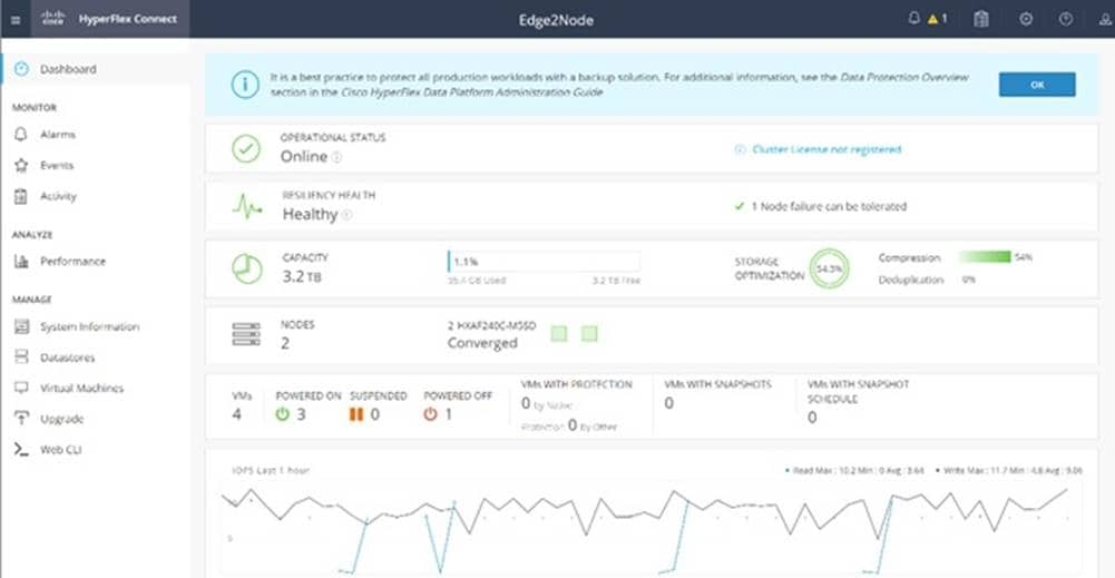
From the Dashboard view, several elements are presented:
● Cluster operational status, overall cluster health, and the cluster’s current node failure tolerance.
● Cluster storage capacity used and free space, compression and deduplication savings, and overall cluster storage optimization statistics.
● Cluster size and individual node health.
● Cluster IOPs, storage throughput, and latency for the past 1 hour.
HyperFlex Connect provides for additional monitoring capabilities, including:
● Alarms: Cluster alarms can be viewed, acknowledged, and reset.
● Event Log: The cluster event log can be viewed, specific events can be filtered for, and the log can be exported.
● Activity Log: Recent job activity, such as ReadyClones can be viewed, and the status can be monitored.
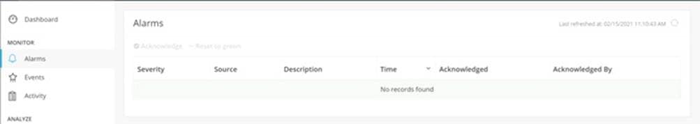
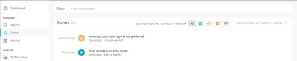
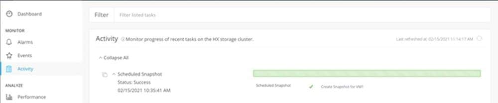
The historical and current performance of the HyperFlex cluster can be analyzed via the built-in performance charts. The default view shows read and write IOPs, bandwidth, and latency over the past 1 hour for the entire cluster. Views can be customized to see individual nodes or datastores, change the timeframe shown in the charts, and change if read, write, or aggregate values are shown.
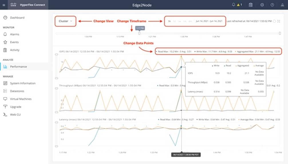
HyperFlex Connect is used as the management tool for all configuration of HyperFlex Data Protection features, including VM replication and data-at-rest encryption. If the system has been configured for N:1 replication via Cisco Intersight, this menu selection will be hidden from view.
HyperFlex Connect presents several views and elements for managing the HyperFlex cluster:
● System Information: Presents a detailed view of the cluster configuration, software revisions, hosts, disks, and cluster uptime. Views of the individual nodes and the individual disks are available. In these views, nodes can be placed into HX Maintenance Mode, and self-encrypting disks can be securely erased.
● Datastores: Presents the datastores present in the cluster, and allows for datastores to be created, mounted, unmounted, edited or deleted, as described earlier in this document as part of the cluster setup.
● Virtual Machines: Presents the VMs present in the cluster and allows for the VMs to be powered on or off, cloned via HX ReadyClone, Snapshots taken and scheduled, and protected via native replication.
● Upgrade: One-click upgrades to the HXDP software, ESXi host software and Cisco UCS firmware can be initiated from this view.
● Web CLI: A web-based interface, from which CLI commands can be issued and their output seen, as opposed to directly logging into the SCVMs via SSH.
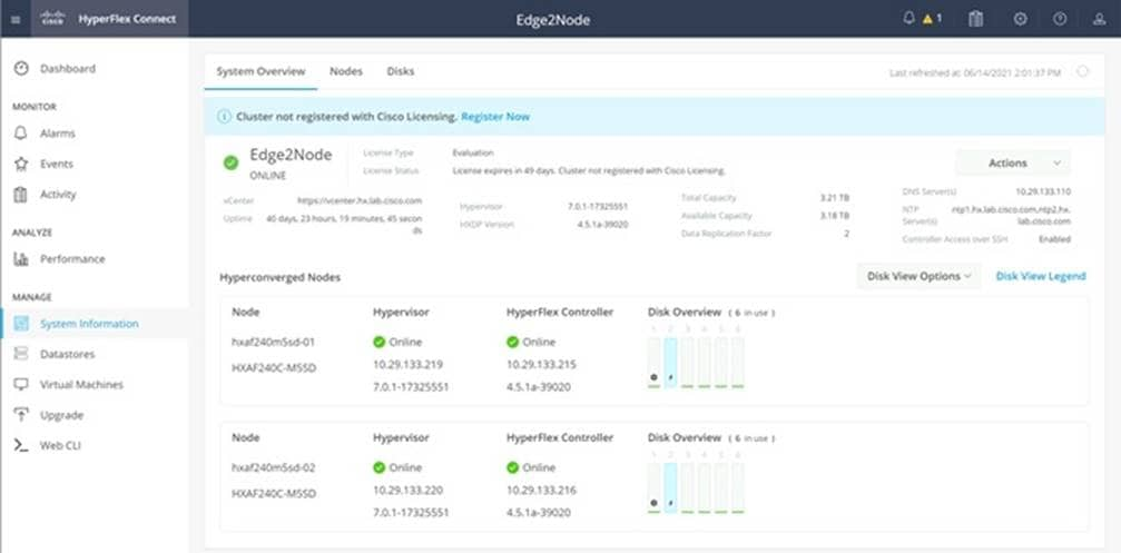
Cisco Intersight Cloud-Based Management
Cisco Intersight management is enabled via embedded code running on the Cisco UCS Fabric Interconnects, and in the Cisco HyperFlex software, known as device connectors. To enable Intersight management, the device connectors are registered online at the Cisco Intersight website, https://intersight.com when logged into the website with a valid cisco.com account used to manage your environments. Cisco Intersight can be used to manage and monitor HyperFlex clusters and UCS domains with the following software revisions:
● Cisco UCS Manager and Infrastructure Firmware version 3.2 and later
● Cisco HyperFlex software version 2.5(1a) or later
The Cisco UCS Fabric Interconnects, and the Cisco HyperFlex nodes must have DNS lookup capabilities and access to the internet. If direct access to the internet is not available, the systems can be configured to connect via an HTTPS proxy server.
Cisco Intersight is offered in several editions; a Base license which is free to use and offers a large variety of monitoring, inventory and reporting features, plus added cost tiers named Essentials, Advanced and Premier. New features and capabilities will be added to the different licensing tiers over time. A 90-day trial of all premier Intersight features is available for use as an evaluation period. Cisco Intersight must be registered with the Cisco Smart Software Manager (SSM) through a valid Cisco Smart Account. Before beginning, verify that you have a Cisco Smart account, and valid Intersight licenses are available in your account. Intersight licenses are sold per managed node, so ensure that there are enough licenses to cover all of the Cisco HyperFlex nodes in the cluster.
To create a Smart Account, see Cisco Software Central > Request a Smart Account https://webapps.cisco.com/software/company/smartaccounts/home?route=module/accountcreation .
To configure Cisco Intersight licensing, follow these steps:
1. Using a web browser, log on to the Cisco Intersight webpage at https://intersight.com (you must have a valid cisco.com CCO account).
2. In the Dashboards view, click the gear shaped icon in the upper right-hand corner, then click Licensing.
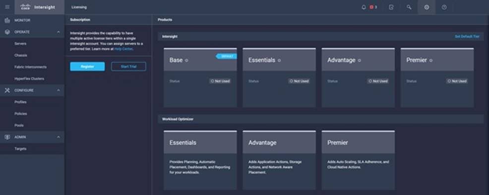
3. If desired, click Start Trial, then in the pop-up window that appears, click Start to begin a 90-day trial of all Intersight features.
4. If you have purchased Intersight Licensing and they are active in your Cisco Smart Account, Navigate to Cisco Software Central (https://software.cisco.com/) and log in to your Smart Account.
5. From Cisco Smart Software Manager, generate a registration token.
6. In Intersight, click Register License.
7. Enter the registration token, then click Next.
8. Set the default licensing tier level, and if desired check the box to move all existing servers to this tier, then click Register.
Cisco Intersight HyperFlex Management
Cisco HyperFlex clusters which are deployed via Cisco Intersight following the instructions from earlier in this document, will already be managed by Cisco Intersight. It is possible to connect existing Cisco HyperFlex Edge clusters to Intersight as well, allowing all systems to be managed in a consistent manner. To connect Cisco Intersight to the Cisco HyperFlex cluster(s) in your environments, follow these steps:
Connect Cisco HyperFlex Clusters
To connect existing Cisco HyperFlex Clusters, follow these steps:
1. Open a web browser and navigate to the Cisco Intersight Cloud Management platform https://intersight.com/.
2. Login with your Cisco ID and password.
3. To Claim a new device, from the left-hand Navigation pane, underneath ADMIN, click Targets, in the Targets window, choose Claim a New Target.
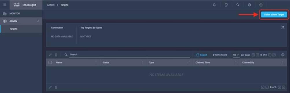
4. Select the target type named Cisco HyperFlex Cluster, then click Start.
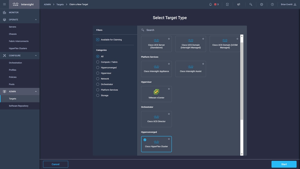
5. In the HyperFlex Connect Dashboard page, click Edit Settings, then click Device Connector.
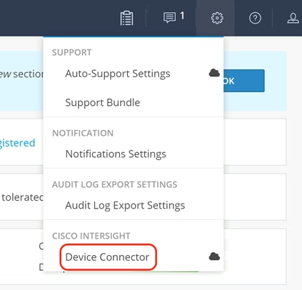
6. If necessary, to modify the Proxy settings, click Settings, and click the Proxy Settings link on the left-hand side. Click the Proxy configuration, then enter the Proxy server IP address or DNS hostname, the TCP port, enable authentication then enter a username and password if necessary, then click Save.
7. If desired, the Access Mode for Cisco Intersight can be set to Read-only, or management can be disabled from this screen. If necessary, custom SSL certificates can also be imported.
8. In the HyperFlex Connect screen, a Device ID, and a Claim Code for this HyperFlex cluster will be shown. Copy these two codes by clicking the clipboard icons and pasting them to the Device ID and Claim Code fields in the Cisco Intersight "Claim A New Target" window, then click Claim.
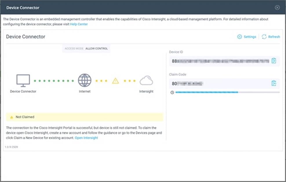
9. The Cisco HyperFlex Cluster will now show the system as Claimed in the Device Connector screen, and the cluster will appear in the Cisco Intersight inventory.
The Cisco Intersight Monitor window provides a single screen overview of all connected Cisco UCS Domains, the servers within those domains, the HyperFlex Clusters running in the domains, along with their health statuses, storage utilization, port counts, and more. Elements on the screen are clickable and will drill down into other sections of the page to view further details.
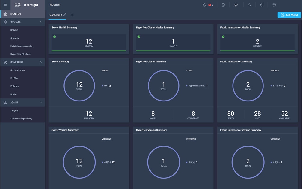
The Servers screen provides details of all the individual servers within the connected and managed UCS domains.
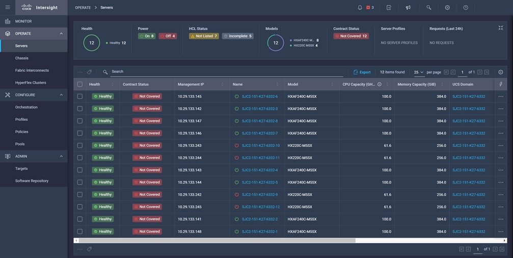
The HyperFlex Clusters screen provides details of all the HyperFlex clusters that are connected and managed by Cisco Intersight. By clicking the ellipses (…) the HyperFlex Connect GUI for the clusters can be directly connected to in another browser window or tab.
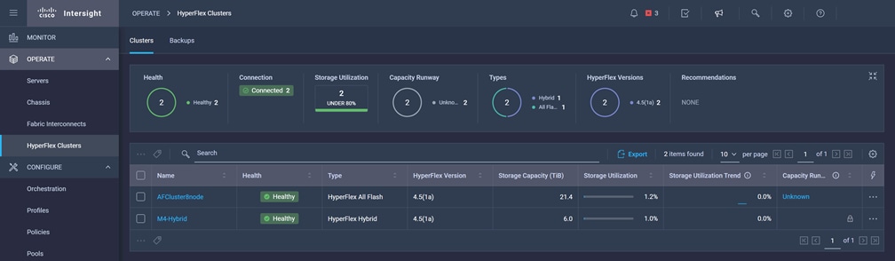
The Fabric Interconnects screen provides details of all the UCS domains that are connected and managed by Cisco Intersight. By clicking the ellipses (…) the Cisco UCS Manager webpage for the domain can be directly connected to in another browser window or tab, or a session can be opened to the CLI of the Fabric Interconnect.
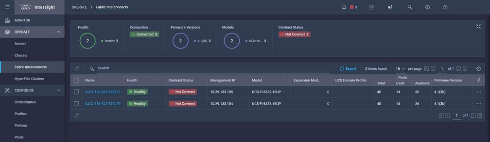
Cisco Intersight Service Profiles and Policies pages are only available with the Intersight Essentials licensing tier or higher, except for configuring a Cisco HyperFlex Cluster Profile as outlined earlier in this document.
In this section, various best practices and guidelines are given for management and ongoing use of the Cisco HyperFlex system. These guidelines and recommendations apply only to the software versions upon which this document is based, listed in Software Components.
For the best possible performance and functionality of the virtual machines that will be created using the HyperFlex ReadyClone feature, the following guidelines for preparation of the base VMs to be cloned should be followed:
● Base VMs must be stored in a HyperFlex datastore.
● All virtual disks of the base VM must be stored in the same HyperFlex datastore.
● Base VMs can only have HyperFlex native snapshots, no VMware redo-log based snapshots can be present.
● For very high IO workloads with many clone VMs leveraging the same base image, it might be necessary to use multiple copies of the same base image for groups of clones. Doing so prevents referencing the same blocks across all clones and could yield an increase in performance. This step is typically not required for most use cases and workload types.
HyperFlex native snapshots are high performance snapshots that are space-efficient, crash-consistent, and application consistent, taken by the HyperFlex Distributed Filesystem, rather than using VMware redo-log based snapshots. For the best possible performance and functionality of HyperFlex native snapshots, the following guidelines should be followed:
● Make sure that the first snapshot taken of a guest VM is a HyperFlex native snapshot, by logging in to the Cisco HyperFlex Connect management page, and choosing Snapshot Now or Schedule Snapshot. Failure to do so reverts to VMware redo-log based snapshots.
● A Sentinel snapshot becomes a base snapshot that all future snapshots are added to and prevents the VM from reverting to VMware redo-log based snapshots. Failure to do so can cause performance degradation when taking snapshots later, while the VM is performing large amounts of storage IO.
● Additional snapshots can be taken via the HyperFlex Connect management webpage, or the standard vSphere client snapshot menu. As long as the initial snapshot was a HyperFlex native snapshot, each additional snapshot is also considered to be a HyperFlex native snapshot.
● Do not delete the Sentinel snapshot unless you are deleting all the snapshots entirely.
● Do not revert the VM to the Sentinel snapshot. (Figure 17)
Figure 17. HyperFlex Sentinel Snapshot
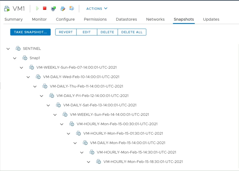
The Cisco HyperFlex Distributed Filesystem can create multiple datastores for storage of virtual machines. While there can be multiple datastores for logical separation, all of the files are located within a single distributed filesystem. As such, performing a storage vMotion of virtual machine disk files has little value in the HyperFlex system. Furthermore, storage vMotion can create additional filesystem consumption and generate additional unnecessary metadata within the filesystem, which must later be cleaned up via the filesystem’s internal cleaner process.
![]() It is recommended to not perform a storage vMotion of a guest VM between datastores within the same HyperFlex cluster. Storage vMotion between different HyperFlex clusters, or between HyperFlex and non-HyperFlex datastores are permitted.
It is recommended to not perform a storage vMotion of a guest VM between datastores within the same HyperFlex cluster. Storage vMotion between different HyperFlex clusters, or between HyperFlex and non-HyperFlex datastores are permitted.
HyperFlex clusters can create multiple datastores for logical separation of virtual machine storage, yet the files are all stored in the same underlying distributed filesystem. The only difference between one datastore and another are their names and their configured sizes. Due to this, there is no compelling reason for a virtual machine’s virtual disk files to be stored on a particular datastore versus another.
![]() All of the virtual disks that make up a single virtual machine must be placed in the same datastore. Spreading the virtual disks across multiple datastores provides no benefit, can cause ReadyClone and Snapshot errors, and lead to degraded performance in stretched clusters.
All of the virtual disks that make up a single virtual machine must be placed in the same datastore. Spreading the virtual disks across multiple datastores provides no benefit, can cause ReadyClone and Snapshot errors, and lead to degraded performance in stretched clusters.
Cisco HyperFlex clusters which have been originally installed using HXDP version 4.0(1b) or later no longer require the use of "HX Maintenance Mode" in order to evacuate the converged nodes for reboots, patches, or other work. Use of the standard enter/exit maintenance mode available in the vCenter web client or HTML5 web client is sufficient. Clusters which are upgraded from earlier revisions to version 4.0(1b) or later can also use standard vSphere maintenance mode, after undergoing a process to remove vSphere ESX Agent Manager (EAM) components and settings that are no longer required. These instructions are available upon request from your Cisco sales team or technical support contacts.
This section provides a list of items that should be reviewed after the HyperFlex system has been deployed and configured. The goal of this section is to verify the configuration and functionality of the solution and ensure that the configuration supports core availability requirements.
The following tests are critical for the functionality of the solution and should be verified before deploying for production:
1. Verify the expected number of converged storage nodes are members of the HyperFlex cluster in the HyperFlex Connect Dashboard summary screen.
2. Verify the expected cluster capacity is seen in the HyperFlex Connect Dashboard summary screen. (See Appendix A)
3. Create a test virtual machine that accesses the HyperFlex datastore and is able to perform read/write operations.
4. Perform a virtual machine migration (vMotion) of the test virtual machine to a different host on the cluster.
5. During the vMotion of the virtual machine, make sure the test virtual machine can perform a continuous ping to its default gateway and to check if the network connectivity is maintained during and after the migration.
The following redundancy checks can be performed to verify the robustness of the system when deployed using a dual redundant switch configuration. Network traffic, such as a continuous ping from VM to VM, or from vCenter to the ESXi hosts should not show significant failures (one or two ping drops might be observed at times). Also, all of the HyperFlex datastores must remain mounted and accessible from all the hosts at all times.
1. Administratively disable one of the 10/25 GbE ports on switch A which is connected to one of the HyperFlex converged storage hosts. The ESXi virtual switch uplinks for fabric A should now show as failed, and the standby uplinks on fabric B will be in use for the management and vMotion virtual switches. Upon administratively re-enabling the port, the uplinks in use should return to normal.
2. Administratively disable one of the 10/25 GbE ports on switch B which is connected to one of the HyperFlex converged storage hosts. The ESXi virtual switch uplinks for fabric B should now show as failed, and the standby uplinks on fabric A will be in use for the storage virtual switch. Upon administratively re-enabling the port, the uplinks in use should return to normal.
3. Place a representative load of guest virtual machines on the system. Put one of the ESXi hosts in maintenance mode. All the VMs running on that host should be migrated via vMotion to other active hosts through vSphere DRS, except for the storage platform controller VM, which will be powered off. No guest VMs should lose any network or storage accessibility during or after the migration. This test assumes that enough RAM is available on the remaining ESXi hosts to accommodate VMs from the host put in maintenance mode. The HyperFlex cluster will show in an unhealthy state in the HX Connect Dashboard.
4. Reboot the host that is in maintenance mode and exit it from maintenance mode after the reboot. The storage platform controller will automatically start when the host exits maintenance mode. The HyperFlex cluster will show as healthy in the HX Connect Dashboard after a brief time to restart the services on that node. vSphere DRS should rebalance the VM distribution across the cluster over time.
![]() Many vCenter alerts automatically clear when the fault has been resolved. Once the cluster health is verified, some alerts may need to be manually cleared.
Many vCenter alerts automatically clear when the fault has been resolved. Once the cluster health is verified, some alerts may need to be manually cleared.
5. Reboot one of the two network switches while traffic is being sent and received on the storage datastores and the network. The reboot should not affect the proper operation of storage access and network traffic generated by the VMs. Numerous faults and errors will be noted in vCenter, Cisco Intersight, and HyperFlex Connect, but all will be cleared after the switch comes back online.
A: Cluster Capacity Calculations
A HyperFlex HX Data Platform cluster capacity is calculated as follows:
(((<capacity disk size in GB> X 10^9) / 1024^3) X <number of capacity disks per node> X <number of HyperFlex nodes> X 0.92) / replication factor
Divide the result by 1024 to get a value in TiB
The replication factor value is 3 if the HX cluster is set to RF=3, and the value is 2 if the HX cluster is set to RF=2.
The 0.92 multiplier accounts for an 8% reservation set aside on each disk by the HX Data Platform software for various internal filesystem functions.
Calculation example:
<capacity disk size in GB> = 1200 for 1.2 TB disks
<number of capacity disks per node> = 15 for an HX240c-M4SX model server
<number of HyperFlex nodes> = 8
replication factor = 3
Result: (((1200*10^9)/1024^3)*15*8*0.92)/3 = 41127.2049
41127.2049 / 1024 = 40.16 TiB
A stretched cluster maintains data identically across both halves of the cluster; therefore, it effectively doubles the replication factor. For example, the only allowed replication factor for a stretched cluster is RF2, meaning it will store 2 copies of the data on the nodes in site 1, and also store 2 copies of the data on the nodes in site 2. Because of this, the capacity of a stretched cluster is effectively reduced by 50 percent compared to RF2. The calculation above can use a value of 4 for the replication factor to determine the capacity of a stretched cluster.
HyperFlex sizer is a cloud-based tool that can help customers and partners determine how many Cisco HyperFlex nodes are needed, and how the nodes should be configured to meet their needs for the compute resources, storage capacity and performance requirements in the datacenter. The sizing guidance for the proposed HyperFlex system is calculated according to the anticipated workload information entered by the user. The HyperFlex sizer tool is regularly updated with new features to support the currently available hardware and deployment options available in Cisco HyperFlex, and also to more accurately model different workloads. This cloud application can be accessed from anywhere at the following website (CCO login required): https://hyperflexsizer.cloudapps.cisco.com
Improvements in the HyperFlex sizing tool include:
● Support for HyperFlex Boost Mode
● Support for all-NVMe and Acceleration Cards for HyperFlex stretch clusters
● Support for Cisco model 64108 Fabric Interconnects
● Support for iSCSI workloads for DB and Raw disk use
● Intersight based UI design
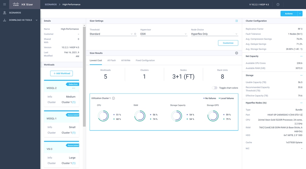
![]() The HyperFlex Sizer tool is designed to provide general guidance in evaluating the optimum solution for using selected Cisco products. The tool is not intended as a substitute for your own judgment or for that of your professional advisors.
The HyperFlex Sizer tool is designed to provide general guidance in evaluating the optimum solution for using selected Cisco products. The tool is not intended as a substitute for your own judgment or for that of your professional advisors.
C: HyperFlex Workload Profiler
Also available at the https://hyperflexsizer.cloudapps.cisco.com website is an updated HyperFlex Workload Profiler, version 3.1.12. The HyperFlex Workload Profiler tool is used to capture storage usage and performance statistics from an existing VMware ESX cluster, enabling you to use that data to assist with sizing a HyperFlex cluster which would assume that workload. The workload profiler is distributed as an OVA file, which can be deployed using static or DHCP assigned addressing, on an existing VMware ESXi host. Once deployed, the profiler tool connects to an existing VMware vCenter server to gather storage statistics for the selected ESXi hosts. To capture performance data using the HyperFlex Workload Profiler, follow these steps:
1. Deploy the HyperFlex Workload Profiler VM by using the Deploy OVF Template wizard, on the chosen existing ESXi host. Assign a static IP address or use DHCP addressing as part of the deployment wizard and set the default password.
2. Using a web browser, navigate to the IP address assigned or leased by the Workload Profiler VM.
3. Enter the username and password, the default username is "monitoring", and use the password previously entered, then click Login.
4. On first login, a wizard to add a system to be monitored will run. Enter the vCenter server name or IP, a username with administrative rights, and the password, then click Connect.
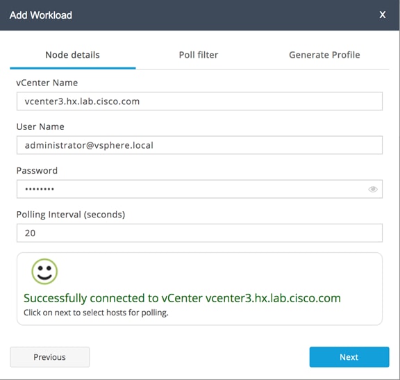
5. When the vCenter server is connected, click Next to select the hosts to monitor.
6. Check the box or boxes next to the hosts to poll for data, then click Next.
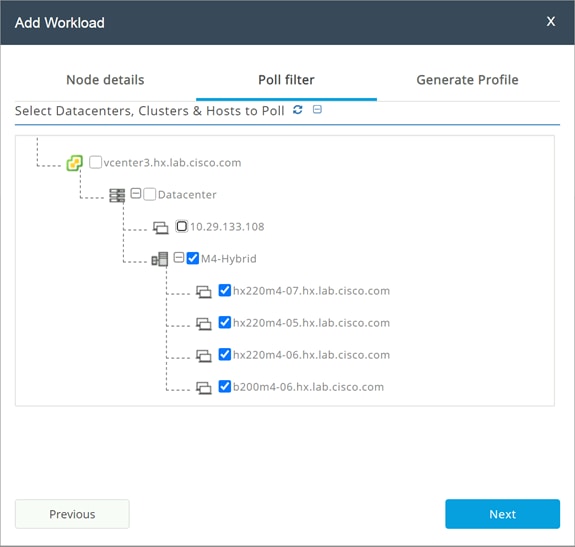
7. Choose to generate a Quick Profile, which will not generate detailed performance data, or a Detailed Profile, then click Save.
8. In the main screen, the vCenter server being polled will be listed. Click Start Profiling.
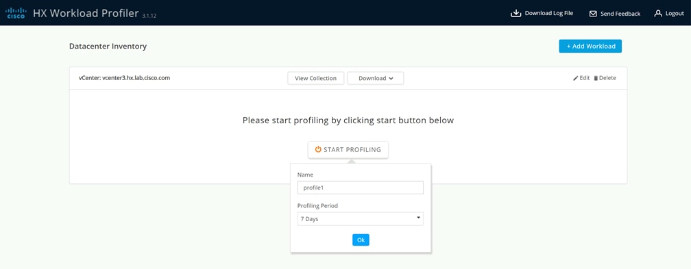
9. Choose a time interval to collect data on the system, then click OK. A 30-day collection is recommended for accurate sizing activities.
10. At any time during the collection polling, the data can be viewed by clicking View Collection. The data for CPU and memory utilization, and storage statistics can be viewed, as an aggregate of all hosts, one host at a time, or from a per VM perspective.
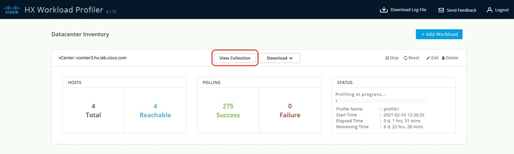
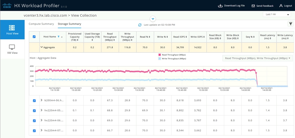
11. When the collection is complete, the complete dataset can be exported as a comma-separated file, and the data can be automatically imported into the HyperFlex sizer tool to help with computing and storage sizing efforts, or otherwise analyzed to help with sizing decisions.
Also available at the https://hyperflexsizer.cloudapps.cisco.com website is the HyperFlex Bench tool, version 2.0. HyperFlex Bench is a tool used to perform benchmarking tests of a HyperFlex system, which utilizes the freely available Vdbench tool, in an easy-to-use web interface. Installation is done by downloading and deploying the HyperFlex Bench manager VM to the HyperFlex cluster using an OVA file. Afterwards, benchmark testing is done by connecting to the management webpage, configuring VM groups and a test profile, then executing a benchmark test. HyperFlex Bench deploys the defined load generating VMs onto the HyperFlex clustered system under test (SUT) then uses them to generate the load defined in the test profile, collecting the data via the network. HyperFlex Bench requires two networks; one publicly available network for the configuration and management of the tool, and a second private network which the load generating VMs use for their configuration and data reporting. The public network is where the HyperFlex Bench webpage is accessed, and also the network where it will communicate with the managing vCenter Server of the HyperFlex system under test. The private network can be a VLAN/subnet, which is accessible via a port group for guest VMs available across the HyperFlex cluster being benchmarked. For example, the public network can use the "Storage Controller Management Network" port group, and the private network can use the "vm-network-100" port group.
To run a benchmark performance test using the HyperFlex Bench, follow these steps:
1. Deploy the HyperFlex Bench VM by using the Deploy OVF Template wizard, on the chosen existing ESXi host. Assign a static IP address or use DHCP addressing as part of the deployment wizard and set the default password. Assign the public and private networks as appropriate.
2. Using a web browser, navigate to the IP address assigned or leased by the HyperFlex Bench VM. Log in with the username "appadmin" and the password set during the OVA deployment. Upon the first login, a wizard will ask you to upload a copy of the Vdbench application executables and connect to the managing vCenter server.
3. Upload a copy of the Vdbench application .zip file, as downloaded from Oracle. A valid login is required to download the file from the Oracle website.
4. Enter the URL or IP address and the credentials to connect to the vCenter server managing this HyperFlex Bench VM and the HyperFlex cluster to be tested.
5. Create a VM Group to define the VMs which will generate the load. Click VM Groups, then click Create VM Group. Enter the desired values for the HyperFlex cluster, the HX datastore, the guest VM network, the disk size, and the total number of VMs to deploy, then click Save.
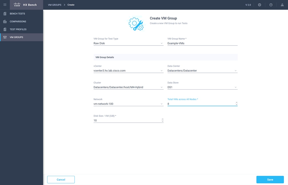
6. Monitor the progress of the VM Group deployment. After it is complete, the group is marked as Ready for Use, then you may continue with creating a test profile and starting a benchmark job.
7. Create a custom test profile, if desired, by clicking Test Profiles, then click Create Test Profile. Enter the values for the test workload, making sure to keep the dataset size per VM under the size of the disk created per VM in the previous step, then click Save. Optionally, you can choose to upload a Vdbench configuration file for more advanced options and settings if you have one.
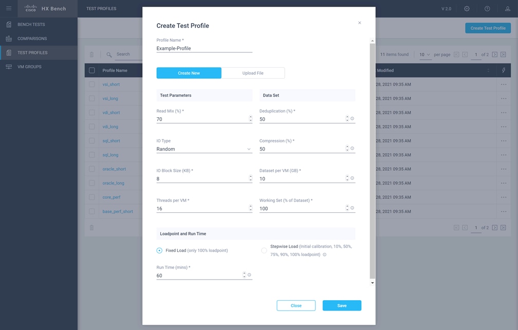
8. Click Bench Tests, then click Create Test to create a test using either one of the included profiles, or the custom profile of your own design, then click Next.
9. Select the existing VM Group you created, or optionally create a new group. Choose to include or skip disk priming, and when to start the benchmark run, then click Next. For the most accurate real-world representative results, you should always choose to prime the disks for each test.
10. Review the benchmark job configuration and finally, click Start Test.
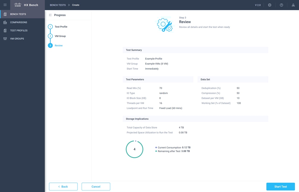
11. Observe the job as it begins to ensure it properly primes the disks and the benchmark test runs.
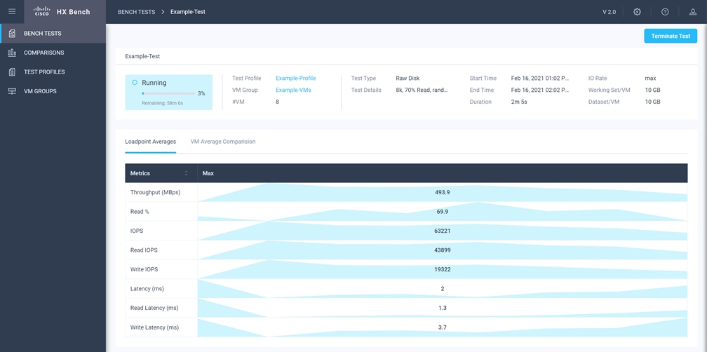
12. After the benchmark run completes, view the results of the test, and optionally view the job logs or download a report in PDF or CSV format.
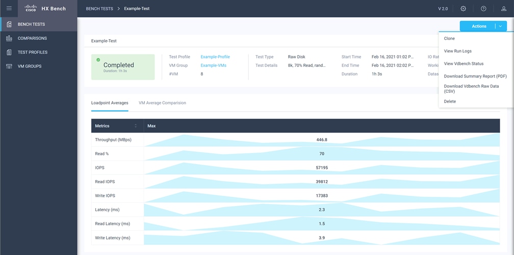
E: Example Cisco Nexus 9372 Switch Configurations
feature nxapi
cfs eth distribute
feature interface-vlan
feature lacp
feature vpc
feature lldp
clock timezone PST -8 0
clock summer-time PDT 2 Sunday March 02:00 1 Sunday November 02:00 60
ip domain-lookup
no service unsupported-transceiver
ntp server 3.ntp.esl.cisco.com use-vrf management
ntp server 2.ntp.esl.cisco.com use-vrf management
ntp server 1.ntp.esl.cisco.com use-vrf management
vlan 1
vlan 51
name Cluster1
vlan 52
name Cluster2
vlan 53
name Cluster3
vlan 54
name Cluster4
vlan 100
name VM
vlan 133
name Cisco
vlan 150
name Replication
vlan 200
name VMotion
vrf context management
ip domain-name cisco.com
ip name-server 10.29.133.110
ip route 0.0.0.0/0 10.29.133.1
vpc domain 50
role priority 10
peer-keepalive destination 10.29.133.102 source 10.29.133.101
delay restore 150
auto-recovery
interface Vlan1
interface port-channel50
description VPC-Peer
switchport mode trunk
spanning-tree port type network
vpc peer-link
interface Ethernet1/1
description uplink_vlan133
switchport access vlan 133
spanning-tree port type network
interface Ethernet1/11
description HX-Edge-ports
switchport mode trunk
switchport trunk allowed vlan 51,100,133,150,200
spanning-tree port type edge trunk
interface Ethernet1/12
description HX-Edge-ports
switchport mode trunk
switchport trunk allowed vlan 51,100,133,150,200
spanning-tree port type edge trunk
interface Ethernet1/13
description HX-Edge-ports
switchport mode trunk
switchport trunk allowed vlan 51,100,133,150,200
spanning-tree port type edge trunk
interface Ethernet1/14
description HX-Edge-ports
switchport mode trunk
switchport trunk allowed vlan 52,100,133,150,200
spanning-tree port type edge trunk
interface Ethernet1/15
description HX-Edge-ports
switchport mode trunk
switchport trunk allowed vlan 52,100,133,150,200
spanning-tree port type edge trunk
interface Ethernet1/16
description HX-Edge-ports
switchport mode trunk
switchport trunk allowed vlan 52,100,133,150,200
spanning-tree port type edge trunk
interface Ethernet1/47
description NX9372-A_P1/47--NX9372-B_P1/47
switchport mode trunk
channel-group 50 mode active
interface Ethernet1/48
description NX9372-A_P1/48--NX9372-B_P1/48
switchport mode trunk
channel-group 50 mode active
interface mgmt0
vrf member management
ip address 10.29.133.101/24
line console
line vty
boot nxos bootflash:/nxos.9.3.3.bin
feature nxapi
cfs eth distribute
feature interface-vlan
feature lacp
feature vpc
feature lldp
clock timezone PST -8 0
clock summer-time PDT 2 Sunday March 02:00 1 Sunday November 02:00 60
ip domain-lookup
no service unsupported-transceiver
ntp server 3.ntp.esl.cisco.com use-vrf management
ntp server 2.ntp.esl.cisco.com use-vrf management
ntp server 1.ntp.esl.cisco.com use-vrf management
vlan 1
vlan 51
name Cluster1
vlan 52
name Cluster2
vlan 53
name Cluster3
vlan 54
name Cluster4
vlan 100
name VM
vlan 133
name Cisco
vlan 150
name Replication
vlan 200
name VMotion
vrf context management
ip domain-name cisco.com
ip name-server 10.29.133.110
ip route 0.0.0.0/0 10.29.133.1
vpc domain 50
role priority 10
peer-keepalive destination 10.29.133.101 source 10.29.133.102
delay restore 150
auto-recovery
interface Vlan1
interface port-channel50
description VPC-Peer
switchport mode trunk
spanning-tree port type network
vpc peer-link
interface Ethernet1/1
description uplink_vlan133
switchport access vlan 133
spanning-tree port type network
interface Ethernet1/11
description HX-Edge-ports
switchport mode trunk
switchport trunk allowed vlan 51,100,133,150,200
spanning-tree port type edge trunk
interface Ethernet1/12
description HX-Edge-ports
switchport mode trunk
switchport trunk allowed vlan 51,100,133,150,200
spanning-tree port type edge trunk
interface Ethernet1/13
description HX-Edge-ports
switchport mode trunk
switchport trunk allowed vlan 51,100,133,150,200
spanning-tree port type edge trunk
interface Ethernet1/14
description HX-Edge-ports
switchport mode trunk
switchport trunk allowed vlan 52,100,133,150,200
spanning-tree port type edge trunk
interface Ethernet1/15
description HX-Edge-ports
switchport mode trunk
switchport trunk allowed vlan 52,100,133,150,200
spanning-tree port type edge trunk
interface Ethernet1/16
description HX-Edge-ports
switchport mode trunk
switchport trunk allowed vlan 52,100,133,150,200
spanning-tree port type edge trunk
interface Ethernet1/47
description NX9372-B_P1/47--NX9372-A_P1/47
switchport mode trunk
channel-group 50 mode active
interface Ethernet1/48
description NX9372-B_P1/48--NX9372-A_P1/48
switchport mode trunk
channel-group 50 mode active
interface mgmt0
vrf member management
ip address 10.29.133.102/24
line console
line vty
boot nxos bootflash:/nxos.9.3.3.bin
Brian Everitt, Technical Marketing Engineer, Computing Systems Product Group, Cisco Systems, Inc.
Brian is an IT industry veteran with over 22 years of experience deploying server, network, and storage infrastructures for companies around the world. During his tenure at Cisco, he has been a lead Advanced Services Solutions Architect for Microsoft solutions, virtualization, and SAP Hana on Cisco UCS. Currently his role covers solutions development for Cisco’s HyperFlex Hyperconverged Infrastructure product line, focusing on performance evaluation and product quality. Brian has earned multiple certifications from Microsoft, Cisco, and VMware.
The author wishes to acknowledge the following individual for their significant assistance and technical guidance as part of the testing and creation of this document, the scripts, and the overall solution:
Archana Sharma, Engineering Technical Leader, Computing Systems Product Group, Cisco Systems, Inc.
For comments and suggestions about this guide and related guides, join the discussion on Cisco Community at https://cs.co/en-cvds.