FlexPod for Epic EHR
Available Languages
Bias-Free Language
The documentation set for this product strives to use bias-free language. For the purposes of this documentation set, bias-free is defined as language that does not imply discrimination based on age, disability, gender, racial identity, ethnic identity, sexual orientation, socioeconomic status, and intersectionality. Exceptions may be present in the documentation due to language that is hardcoded in the user interfaces of the product software, language used based on RFP documentation, or language that is used by a referenced third-party product. Learn more about how Cisco is using Inclusive Language.
- US/Canada 800-553-2447
- Worldwide Support Phone Numbers
- All Tools
 Feedback
 Feedback
Published: November 2022
![]()
In partnership with:
About the Cisco Validated Design Program
The Cisco Validated Design (CVD) program consists of systems and solutions designed, tested, and documented to facilitate faster, more reliable, and more predictable customer deployments. For more information, go to: http://www.cisco.com/go/designzone.
The FlexPod Datacenter solution is a validated approach for deploying Cisco® and NetApp technologies and products to build shared private and public cloud infrastructure. Cisco and NetApp have partnered to deliver a series of FlexPod solutions that enable strategic data-center platforms. The success of the FlexPod solution is driven through its ability to evolve and incorporate both technology and product innovations in the areas of management, compute, storage, and networking. This document provides a detailed overview of the FlexPod architecture for Epic and covers the setup and installation of FlexPod to deploy Epic for healthcare. This document explains the design details of incorporating the Cisco X-Series modular platform into the FlexPod Datacenter and the ability to manage and orchestrate FlexPod components from the cloud using Cisco Intersight. Some of the key advantages of integrating Cisco UCS X-Series into the FlexPod infrastructure are:
● Simpler and programmable infrastructure: infrastructure as a code delivered through a single partner integrable open API
● Power and cooling innovations: higher power headroom and lower energy loss due to a 54V DC power delivery to the chassis
● Better airflow: midplane-free design with fewer barriers, therefore lower impedance
● Fabric innovations: PCIe/Compute Express Link (CXL) topology for heterogeneous compute and memory composability
● Innovative cloud operations: continuous feature delivery and no need for maintaining on-premise virtual machines supporting management functions
● Built for investment protections: design ready for future technologies such as liquid cooling and high-Wattage CPUs; CXL-ready
In addition to the compute-specific hardware and software innovations, the integration of the Cisco Intersight cloud platform with VMware vCenter and NetApp Active IQ Unified Manager delivers monitoring, orchestration, and workload optimization capabilities for different layers (virtualization and storage) of the FlexPod infrastructure. The modular nature of the Cisco Intersight platform also provides an easy upgrade path to additional services, such as workload optimization and Kubernetes.
Customers interested in understanding the FlexPod design and deployment details, including the configuration of various elements of design and associated best practices, should refer to Cisco Validated Designs for FlexPod, here: https://www.cisco.com/c/en/us/solutions/design-zone/data-center-design-guides/flexpod-design-guides.html
Solution Overview
Introduction
The Cisco Unified Compute System (Cisco UCS) X-Series is a brand-new modular compute system, configured and managed from the cloud. It is designed to meet the needs of modern applications and to improve operational efficiency, agility, and scale through an adaptable, future-ready, modular design. The Cisco Intersight platform is a Software-as-a-Service (SaaS) infrastructure lifecycle management platform that delivers simplified configuration, deployment, maintenance, and support. FlexPod systems deployed to host Epic HyperSpace, InterSystems Iris database, Cogito Clarity analytics and reporting suite, and services servers hosting the Epic application layer provide an integrated platform for a dependable, high-performance infrastructure that can be deployed rapidly.
Powered by the Cisco Intersight cloud-operations platform, the Cisco UCS X-Series enables the next-generation cloud-operated FlexPod infrastructure that not only simplifies data-center management but also allows the infrastructure to adapt to the unpredictable needs of modern applications as well as traditional workloads. With the Cisco Intersight platform, customers get all the benefits of SaaS delivery and the full lifecycle management of Intersight-connected distributed servers and integrated NetApp storage systems across data centers, remote sites, branch offices, and edge environments.
Audience
The intended audience of this document includes but is not limited to IT architects, sales engineers, field consultants, professional services, IT managers, partner engineering, and customers who want to take advantage of an infrastructure built to deliver IT efficiency and enable IT innovation.
This document provides design guidance around incorporating the Cisco Intersight—managed UCS X-Series platform within FlexPod Datacenter infrastructure for deploying Epic Electronic Health Records (EHR). The document introduces various design elements and covers various considerations and best practices for a successful deployment. The document also highlights the design and product requirements for integrating virtualization and storage systems to Cisco Intersight to deliver a true cloud-based integrated approach to infrastructure management.
The following design elements distinguish this version of FlexPod from previous models:
● Integration of Cisco UCS X-Series into FlexPod Datacenter
● Deploying and managing Cisco UCS X-Series from the cloud using Cisco Intersight
● Integration of Cisco Intersight with NetApp Active IQ Unified Manager for storage monitoring and orchestration
● Integration of Cisco Intersight with VMware vCenter for interacting with, monitoring, and orchestrating the virtual environment
● Deployment utilizing Ansible playbooks to automate deployment steps
● Deployment utilizing Terraform scripts to automate deployment steps
By running an Epic environment on the FlexPod architectural foundation, healthcare organizations can expect to see an improvement in staff productivity and a decrease in capital and operating expenses. The FlexPod Datacenter solution with Cisco UCS X-Series, VMware 7.0 U3, and NetApp ONTAP 9.10.1P1 for Epic EHR delivers several benefits specific to the healthcare industry:
● Simplified operations and lowered costs: Eliminate the expense and complexity of legacy proprietary RISC/UNIX platforms by replacing them with a more efficient and scalable shared resource capable of supporting clinicians wherever they are. This solution delivers higher resource utilization for greater ROI.
● Quicker deployment of infrastructure: Whether it’s in an existing data center or a remote location, the integrated and tested design of FlexPod Datacenter with Epic enables customers to have the new infrastructure up and running in less time with less effort.
● Scale-out architecture: Scale SAN and NAS from terabytes to tens of petabytes without reconfiguring running applications.
● Nondisruptive operations: Perform storage maintenance, hardware lifecycle operations, and software upgrades without interrupting the business.
● Secure multitenancy: This benefit supports the increased needs of virtualized server and storage shared infrastructure, enabling secure multitenancy of facility-specific information, particularly if hosting multiple instances of databases and software.
● Pooled resource optimization: This benefit can help reduce physical server and storage controller counts, load balance workload demands, and boost utilization while improving performance.
● Quality of service (QoS): FlexPod offers QoS on the entire stack. Industry-leading QoS storage policies enable differentiated service levels in a shared environment. These policies enable optimal performance for workloads and help in isolating and controlling runaway applications.
● Storage efficiency: Reduce storage costs with the NetApp 7: 1 storage efficiency guarantee.
● Agility: The industry-leading workflow automation, orchestration, and management tools offered by FlexPod systems allow IT to be far more responsive to business requests. These business requests can range from Epic backup and provisioning of additional test and training environments to analytics database replications for population health management initiatives.
● Productivity: Quickly deploy and scale this solution for optimal clinician end- user experiences.
Like all other FlexPod solution designs, FlexPod Datacenter with Cisco UCS X-Series and Intersight is configurable according to demand and usage. Customers can purchase exactly the infrastructure they need for their current application requirements and can then scale up by adding more resources to the FlexPod system or scale out by adding more FlexPod instances. By moving the management from the fabric interconnects into the cloud, the solution can respond to the speed and scale of customer deployments with a constant stream of new capabilities delivered from Intersight software-as-a-service model at cloud-scale.
Epic FlexPod Datacenter architecture is built using the following infrastructure components for compute, network, and storage:
● Cisco Unified Computing System (Cisco UCS)
● Cisco Nexus® and Cisco MDS switches
● NetApp All Flash FAS (AFF) storage systems
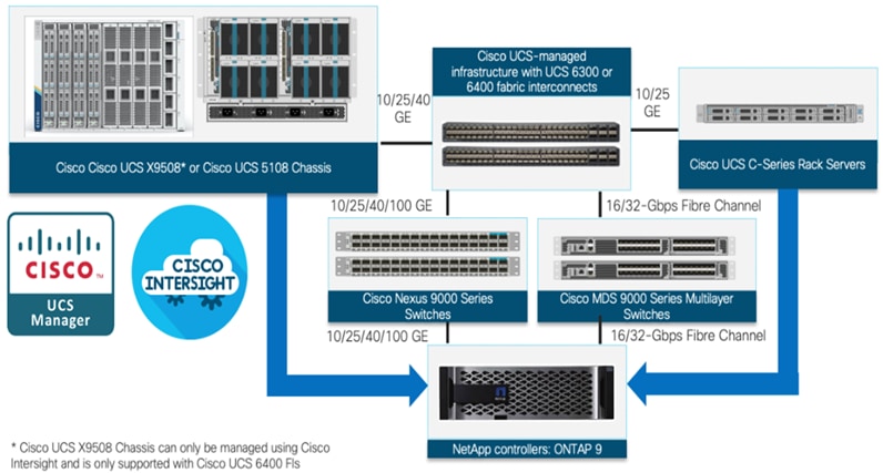
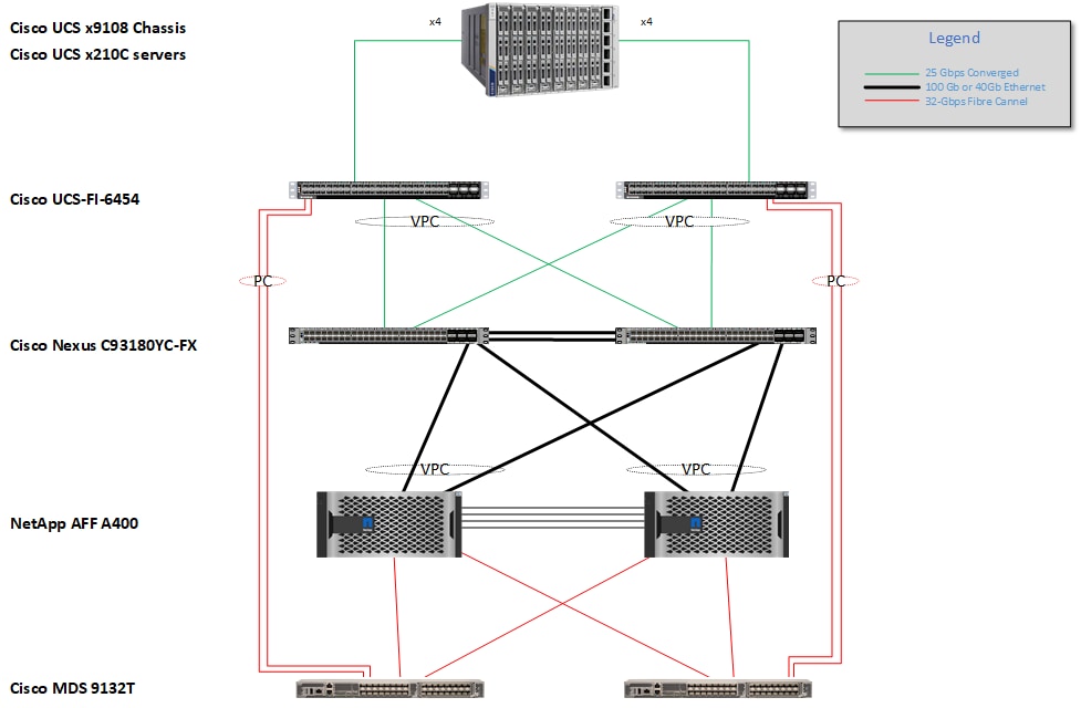
All the FlexPod components have been integrated so that customers can deploy the solution quickly and economically while eliminating many of the risks associated with researching, designing, building, and deploying similar solutions from the foundation. One of the main benefits of FlexPod is its ability to maintain consistency at scale. Each of the component families shown in Figure 1 (Cisco UCS, Cisco Nexus, Cisco MDS, and NetApp controllers) offers platform and resource options to scale up or scale out the infrastructure while supporting the same features.
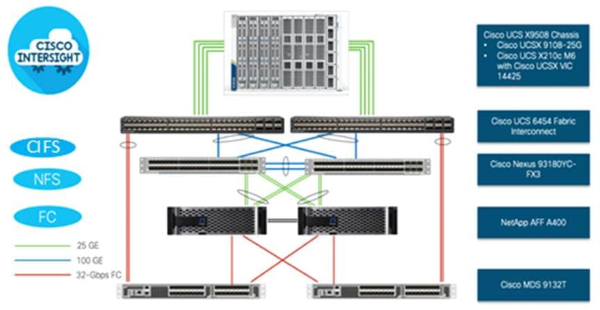
The FlexPod Datacenter solution with Cisco UCS X-Series is built using following hardware components:
● Cisco UCS X9508 Chassis with up to eight Cisco UCS X210c M6 Compute Nodes
● Fourth-generation Cisco UCS 6454 Fabric Interconnects to support 10GbE, 25GbE, and 100GbE connectivity from various components
● High-speed Cisco NX-OS-based Nexus 93180YC-FX3 switching design to support up to 100GE connectivity
● NetApp AFF A400 end-to-end NVMe storage with Fibre Channel connectivity and NFS Storage with high-speed Ethernet.
The software components of the solution consist of:
● Cisco Intersight platform to deploy, maintain and support the FlexPod components
● Cisco Intersight Assist Virtual Appliance to help connect NetApp ONTAP and VMware vCenter with Cisco Intersight
● NetApp Active IQ Unified Manager to monitor and manage the storage and for NetApp ONTAP integration with Cisco Intersight
● VMware vCenter to set up and manage the virtual infrastructure as well as Cisco Intersight integration
These key product highlights and features are described in the following sections.
Cisco Unified Compute System X-Series
The Cisco UCS X-Series Modular System is designed to take the current generation of the Cisco UCS platform to the next level with its future-ready design and cloud-based management. Decoupling and moving the platform management to the cloud allows Cisco UCS to respond to customer feature and scalability requirements in a much faster and efficient manner. Cisco UCS X-Series state of the art hardware simplifies the data-center design by providing flexible server options. A single server type, supporting a broader range of workloads, results in fewer different data-center products to manage and maintain. The Cisco Intersight cloud-management platform manages Cisco UCS X-Series as well as integrating with third-party devices, including VMware vCenter and NetApp storage, to provide visibility, optimization, and orchestration from a single platform, thereby driving agility and deployment consistency.
The various components of the Cisco UCS X-Series are described in the following sections.
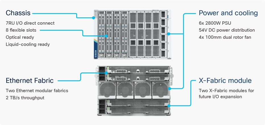
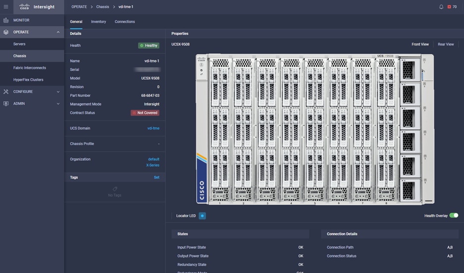
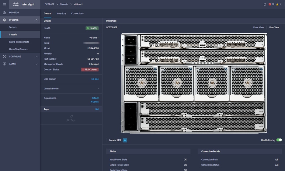
The Cisco UCS X-Series chassis is engineered to be adaptable and flexible. As seen in Figure 3, Cisco UCS X9508 chassis has only a power-distribution midplane. This midplane-free design provides fewer obstructions for better airflow. For I/O connectivity, vertically oriented compute nodes intersect with horizontally oriented fabric modules, allowing the chassis to support future fabric innovations. Cisco UCS X9508 Chassis’ superior packaging enables larger compute nodes, thereby providing more space for actual compute components, such as memory, GPU, drives, and accelerators. Improved airflow through the chassis enables support for higher power components, and more space allows for future thermal solutions (such as liquid cooling) without limitations.
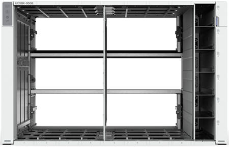
The Cisco UCS X9508 7-Rack-Unit (7RU) chassis has eight flexible slots. These slots can house a combination of compute nodes and a pool of future I/O resources that may include GPU accelerators, disk storage, and nonvolatile memory. At the top rear of the chassis are two Intelligent Fabric Modules (IFMs) that connect the chassis to upstream Cisco UCS 6400 Series Fabric Interconnects. At the bottom rear of the chassis are slots ready to house future X-Fabric modules that can flexibly connect the compute nodes with I/O devices. Six 2800W Power Supply Units (PSUs) provide 54V power to the chassis with N, N+1, and N+N redundancy. A higher voltage allows efficient power delivery with less copper and reduced power loss. Efficient, 100mm, dual counter-rotating fans deliver industry-leading airflow and power efficiency, and optimized thermal algorithms enable different cooling modes to best support the customer’s environment.
Cisco UCS X9108-25G Intelligent Fabric Modules
For the Cisco UCS X9508 Chassis, the network connectivity is provided by a pair of Cisco UCS X9108-25G Intelligent Fabric Modules (IFMs). Like the fabric extenders used in the Cisco UCS 5108 Blade Server Chassis, these modules carry all network traffic to a pair of Cisco UCS 6400 Series Fabric Interconnects (FIs). IFMs also host the Chassis Management Controller (CMC) for chassis management. In contrast to systems with fixed networking components, Cisco UCS X9508’s midplane-free design enables easy upgrades to new networking technologies as they emerge making it straightforward to accommodate new network speeds or technologies in the future.

Each IFM supports eight 25Gb uplink ports for connecting the Cisco UCS X9508 Chassis to the FIs and 32 25Gb server ports for the eight compute nodes. IFM server ports can provide up to 200 Gbps of unified fabric connectivity per compute node across the two IFMs. The uplink ports connect the chassis to the UCS FIs, providing up to 400Gbps connectivity across the two IFMs. The unified fabric carries management, VM, and Fibre Channel over Ethernet (FCoE) traffic to the FIs, where management traffic is routed to the Cisco Intersight cloud operations platform, FCoE traffic is forwarded to the native Fibre Channel interfaces through unified ports on the FI (to Cisco MDS switches), and data Ethernet traffic is forwarded upstream to the data center network (via Cisco Nexus switches).
Cisco UCS X210c M6 Compute Node
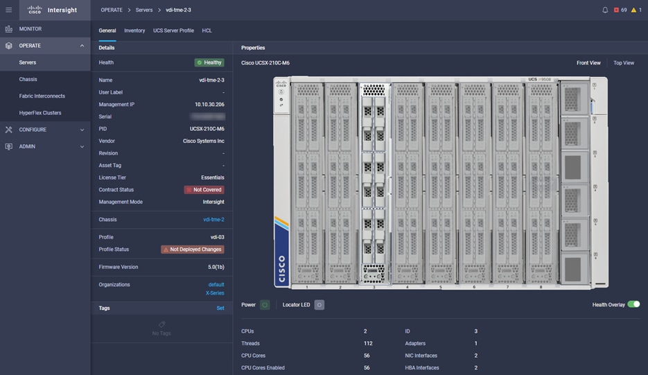
The Cisco UCS X9508 Chassis is designed to host up to 8 Cisco UCS X210c M6 Compute Nodes. The hardware details of the Cisco UCS X210c M6 Compute Nodes are shown in Figure 5:
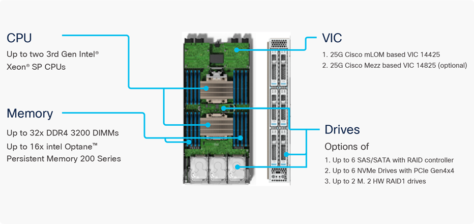
The Cisco UCS X210c M6 features:
● CPU: Up to 2x 3rd Gen Intel Xeon Scalable Processors with up to 40 cores per processor and 1.5 MB Level 3 cache per core
● Memory: Up to 32 x 256 GB DDR4-3200 DIMMs for a maximum of 8 TB of main memory. The Compute Node can also be configured for up to 16 x 512-GB Intel Optane persistent memory DIMMs for a maximum of 12 TB of memory
● Disk storage: Up to 6 SAS or SATA drives can be configured with an internal RAID controller, or customers can configure up to 6 NVMe drives. 2 M.2 memory cards can be added to the Compute Node with RAID 1 mirroring.
● Virtual Interface Card (VIC): Up to 2 VICs including an mLOM Cisco VIC 14425 and a mezzanine Cisco VIC card 14825 can be installed in a Compute Node.
● Security: The server supports an optional Trusted Platform Module (TPM). Additional security features include a secure boot FPGA and ACT2 anticounterfeit provisions.
Cisco UCS Virtual Interface Cards (VICs)
Cisco UCS X210c M6 Compute Nodes support the following two Cisco fourth-generation VIC cards:
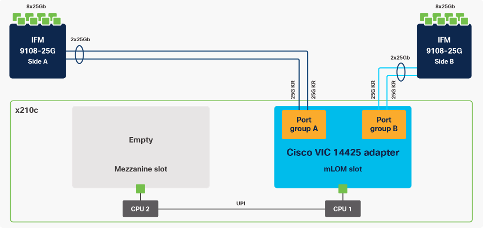
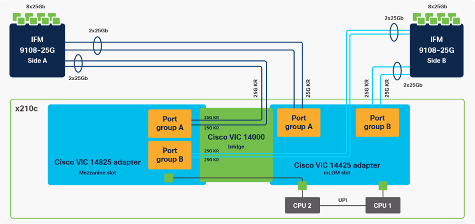
Cisco VIC 14425 fits the mLOM slot in the Cisco X210c Compute Node and enables up to 50 Gbps of unified fabric connectivity to each of the chassis IFMs for a total of 100 Gbps of connectivity per server. Cisco VIC 14425 connectivity to the IFM and up to the fabric interconnects is delivered through 4x 25-Gbps connections, which are configured automatically as 2x 50-Gbps port channels. Cisco VIC 14425 supports 256 virtual interfaces (both Fibre Channel and Ethernet) along with the latest networking innovations such as NVMeoF over RDMA (ROCEv2), VxLAN/NVGRE offload, and so on.
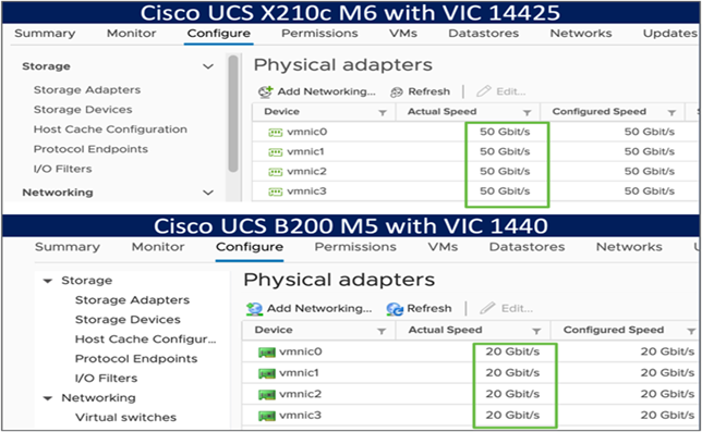
The connections between the 4th generation Cisco VIC (Cisco UCS VIC 1) in the Cisco UCS B200 blades and the I/O modules in the Cisco UCS 5108 chassis comprise of multiple 10Gbps KR lanes. The same connections between Cisco VIC 14425 and IFMs in Cisco UCS X-Series comprise of multiple 25Gbps KR lanes resulting in 2.5x better connectivity in Cisco UCS X210c M6 Compute Nodes. The network interface speed comparison between VMware ESXi installed on Cisco UCS B200 M5 with VIC 1440 and Cisco UCS X210c M6 with VIC 14425 is shown in Figure 7.
The optional Cisco VIC 14825 fits the mezzanine slot on the server. A bridge card (UCSX-V4-BRIDGE) extends this VIC’s 2x 50 Gbps of network connections up to the mLOM slot and out through the mLOM’s IFM connectors, bringing the total bandwidth to 100 Gbps per fabric for a total bandwidth of 200 Gbps per server.
Cisco UCS 6400 Series Fabric Interconnects
The Cisco UCS Fabric Interconnects (FIs) provide a single point for connectivity and management for the entire Cisco UCS system. Typically deployed as an active/active pair, the system’s FIs integrate all components into a single, highly available management domain controlled by the Cisco UCS Manager or Cisco Intersight. Cisco UCS FIs provide a single unified fabric for the system, with low-latency, lossless, cut-through switching that supports LAN, SAN, and management traffic using a single set of cables.
![]()
Cisco UCS 6454 utilized in the current design is a 54-port Fabric Interconnect. This single RU device includes 28 10/25 Gbps Ethernet ports, 4 1/10/25-Gbps Ethernet ports, 6 40/100-Gbps Ethernet uplink ports, and 16 unified ports that can support 10/25 Gigabit Ethernet or 8/16/32-Gbps Fibre Channel, depending on the SFP.
Note: For supporting the Cisco UCS X-Series, the fabric interconnects must be configured in Intersight Managed Mode (IMM). This option replaces the local management with Cisco Intersight cloud- or appliance-based management.
Cisco Intersight
The Cisco Intersight platform is a Software-as-a-Service (SaaS) infrastructure lifecycle management platform that delivers simplified configuration, deployment, maintenance, and support. The Cisco Intersight platform is designed to be modular, so customers can adopt services based on their individual requirements. The platform significantly simplifies IT operations by bridging applications with infrastructure, providing visibility and management from bare-metal servers and hypervisors to serverless applications, thereby reducing costs and mitigating risk. This unified SaaS platform uses a unified Open API design that natively integrates with third-party platforms and tools.
The main benefits of Cisco Intersight infrastructure services are as follows:
● Simplify daily operations by automating many daily manual tasks
● Combine the convenience of a SaaS platform with the capability to connect from anywhere and manage infrastructure through a browser or mobile app
● Stay ahead of problems and accelerate trouble resolution through advanced support capabilities
● Gain global visibility of infrastructure health and status along with advanced management and support capabilities
● Upgrade to add workload optimization and Kubernetes services when needed
Cisco Intersight Virtual Appliance and Private Virtual Appliance
In addition to the SaaS deployment model running on Intersight.com, on-premises options can be purchased separately. The Cisco Intersight Virtual Appliance and Cisco Intersight Private Virtual Appliance are available for organizations that have additional data locality or security requirements for managing systems. The Cisco Intersight Virtual Appliance delivers the management features of the Cisco Intersight platform in an easy-to-deploy VMware Open Virtualization Appliance (OVA) or Microsoft Hyper-V Server virtual machine that allows you to control the system details that leave your premises. The Cisco Intersight Private Virtual Appliance is provided in a form factor specifically designed for users who operate in disconnected (air gap) environments. The Private Virtual Appliance requires no connection to public networks or back to Cisco to operate.
Cisco Intersight Assist helps customers add endpoint devices to Cisco Intersight. A data center could have multiple devices that do not connect directly with Cisco Intersight. Any device that is supported by Cisco Intersight, but does not connect directly with it, will need a connection mechanism. Cisco Intersight Assist provides that connection mechanism. In FlexPod, VMware vCenter and NetApp Active IQ Unified Manager connect to Intersight with the help of Intersight Assist VM.
Cisco Intersight Assist is available within the Cisco Intersight Virtual Appliance, which is distributed as a deployable virtual machine contained within an Open Virtual Appliance (OVA) file format. More details about the Cisco Intersight Assist VM deployment configuration is covered in later sections.
The Cisco Intersight platform uses a subscription-based license with multiple tiers. Customers can purchase a subscription duration of one, three, or five years and select the required Cisco UCS server volume tier for the selected subscription duration. Each Cisco endpoint automatically includes a Cisco Intersight Base license at no additional cost when customers access the Cisco Intersight portal and claim a device. Customers can purchase any of the following higher-tier Cisco Intersight licenses using the Cisco ordering tool:
● Cisco Intersight Essentials: Essentials includes all the functions of the Base license plus additional features, including Cisco UCS Central Software and Cisco Integrated Management Controller (IMC) supervisor entitlement, policy-based configuration with server profiles, firmware management, and evaluation of compatibility with the Cisco Hardware Compatibility List (HCL).
● Cisco Intersight Advantage: Advantage offers all the features and functions of the Base and Essentials tiers. It includes storage widgets and cross-domain inventory correlation across compute, storage, and virtual environments (VMWare ESXi). It also includes OS installation for supported Cisco UCS platforms.
● Cisco Intersight Premier: In addition to all of the functions provided in the Advantage tier, Premier includes full subscription entitlement for Intersight Orchestrator, which provides orchestration across Cisco UCS and third-party systems.
Servers in the Cisco Intersight managed mode require at least the Essentials license. For more information about the features provided in the various licensing tiers, see https://intersight.com/help/getting_started#licensing_requirements
The Cisco Nexus 9000 Series Switches offer both modular and fixed 1/10/25/40/100 Gigabit Ethernet switch configurations with scalability up to 60 Tbps of nonblocking performance with less than five-microsecond latency, wire speed VXLAN gateway, bridging, and routing support.
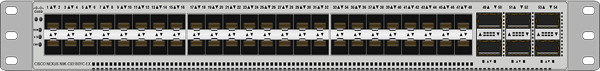
The Cisco Nexus 9000 series switch featured in this design is the Cisco Nexus 93180YC-FX3 configured in NX-OS standalone mode. NX-OS is a purpose-built data-center operating system designed for performance, resiliency, scalability, manageability, and programmability at its foundation. It provides a robust and comprehensive feature set that meets the demanding requirements of virtualization and automation.
The Cisco Nexus 93180YC-FX3 Switch is a 1RU switch that supports 3.6 Tbps of bandwidth and 1.2 bpps. The 48 downlink ports on the 93180YC-FX3 can support 1-, 10-, or 25-Gbps Ethernet, offering deployment flexibility and investment protection. The six uplink ports can be configured as 40- or 100-Gbps Ethernet, offering flexible migration options.
Cisco MDS 9132T 32G Multilayer Fabric Switch
The Cisco MDS 9132T 32G Multilayer Fabric Switch is the next generation of the highly reliable, flexible, and low-cost Cisco MDS 9100 Series switches. It combines high performance with exceptional flexibility and cost effectiveness. This powerful, compact one Rack-Unit (1RU) switch scales from 8 to 32 line-rate 32 Gbps Fibre Channel ports.
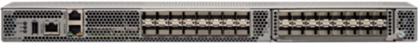
The Cisco MDS 9132T delivers advanced storage networking features and functions with ease of management and compatibility with the entire Cisco MDS 9000 family portfolio for reliable end-to-end connectivity. This switch also offers state-of-the-art SAN analytics and telemetry capabilities that have been built into this next-generation hardware platform. This new state-of-the-art technology couples the next-generation port ASIC with a fully dedicated network processing unit designed to complete analytics calculations in real time. The telemetry data extracted from the inspection of the frame headers are calculated on board (within the switch) and, using an industry-leading open format, can be streamed to any analytics-visualization platform. This switch also includes a dedicated 10/100/1000BASE-T telemetry port to maximize data delivery to any telemetry receiver, including Cisco Data Center Network Manager.
NetApp AFF A-Series controller lineup provides industry leading performance while continuing to provide a full suite of enterprise-grade data management and data protection features. AFF A-Series systems support end-to-end NVMe technologies, from NVMe-attached SSDs to frontend NVMe over Fibre Channel (NVMe/FC) host connectivity. These systems deliver enterprise class performance, making them a superior choice for driving the most demanding workloads and applications. With a simple software upgrade to the modern NVMe/FC SAN infrastructure, you can drive more workloads with faster response times, without disruption or data migration. Additionally, more organizations are adopting a “cloud first” strategy, driving the need for enterprise-grade data services for a shared environment across on-premises data centers and the cloud. As a result, modern all-flash arrays must provide robust data services, integrated data protection, seamless scalability, and new levels of performance — plus deep application and cloud integration. These new workloads demand performance that first-generation flash systems cannot deliver.
For more information about the NetApp AFF A-series controllers, see the AFF product page: https://www.netapp.com/us/products/storage-systems/all-flash-array/aff-a-series.aspx
You can view or download more technical specifications of the AFF A-series controllers here: https://www.netapp.com/us/media/ds-3582.pdf
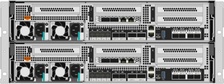
The NetApp AFF A400 offers full end-to-end NVMe support. The frontend NVMe/FC connectivity makes it possible to achieve optimal performance from an all-flash array for workloads that include artificial intelligence, machine learning, and real-time analytics as well as business-critical databases. On the back end, the A400 supports both serial-attached SCSI (SAS) and NVMe-attached SSDs, offering the versatility for current customers to move up from their legacy A-Series systems and satisfying the increasing interest that all customers have in NVMe-based storage.
The NetApp AFF A400 offers greater port availability, network connectivity, and expandability. The NetApp AFF A400 has 10 PCIe Gen3 slots per high availability pair. The NetApp AFF A400 offers 25GbE or 100GbE, as well as 32Gb/FC and NVMe/FC network connectivity. This model was created to keep up with changing business needs and performance and workload requirements by merging the latest technology for data acceleration and ultra-low latency in an end-to-end NVMe storage system.
Note: Cisco UCS X-Series is supported with all NetApp AFF systems running NetApp ONTAP 9 release.
NetApp storage systems harness the power of ONTAP to simplify the data infrastructure from edge, core, and cloud with a common set of data services and 99.9999 percent availability. NetApp ONTAP 9 data management software from NetApp enables customers to modernize their infrastructure and transition to a cloud-ready data center. ONTAP 9 has a host of features to simplify deployment and data management, accelerate and protect critical data, and make infrastructure future-ready across hybrid-cloud architectures.
NetApp ONTAP 9 is the data management software that is used with the NetApp AFF A400 all-flash storage system in this solution design. ONTAP software offers secure unified storage for applications that read and write data over block- or file-access protocol storage configurations. These storage configurations range from high-speed flash to lower-priced spinning media or cloud-based object storage. ONTAP implementations can run on NetApp engineered FAS or AFF series arrays and in private, public, or hybrid clouds (NetApp Private Storage and NetApp Cloud Volumes ONTAP). Specialized implementations offer best-in-class converged infrastructure, featured here as part of the FlexPod Datacenter solution or with access to third-party storage arrays (NetApp FlexArray virtualization). Together these implementations form the basic framework of the NetApp Data Fabric, with a common software-defined approach to data management, and fast efficient replication across systems. FlexPod and ONTAP architectures can serve as the foundation for both hybrid cloud and private cloud designs.
Read more about all the capabilities of ONTAP data management software here: https://www.netapp.com/us/products/data-management-software/ontap.aspx.
ONTAP 9.10 brings additional enhancements in manageability, data protection, networking and security protocols, and SAN and object storage. It also includes updated hardware support, increased MetroCluster IP solution scale, and supports IP-routed MetroCluster IP backend connections. See the ONTAP 9.10 release note below for more details:
https://library.netapp.com/ecm/ecm_download_file/ECMLP2492508
NetApp Active IQ Unified Manager
NetApp Active IQ Unified Manager is a comprehensive monitoring and proactive management tool for NetApp ONTAP systems to help manage the availability, capacity, protection, and performance risks of your storage systems and virtual infrastructure. The Unified Manager can be deployed on a Linux server, on a Windows server, or as a virtual appliance on a VMware host.
Active IQ Unified Manager enables monitoring your ONTAP storage clusters from a single redesigned, intuitive interface that delivers intelligence from community wisdom and AI analytics. It provides comprehensive operational, performance, and proactive insights into the storage environment and the virtual machines running on it. When an issue occurs on the storage infrastructure, Unified Manager can notify you about the details of the issue to help with identifying the root cause. The virtual machine dashboard gives you a view into the performance statistics for the VM so that you can investigate the entire I/O path from the vSphere host down through the network and finally to the storage. Some events also provide remedial actions that can be taken to rectify the issue. You can configure custom alerts for events so that when issues occur, you are notified through email and SNMP Traps. Active IQ Unified Manager enables planning for the storage requirements of your users by forecasting capacity and usage trends to proactively act before issues arise, preventing reactive short-term decisions that can lead to additional problems in the long term.
VMware vSphere is a virtualization platform for holistically managing large collections of infrastructures (resources including CPUs, storage, and networking) as a seamless, versatile, and dynamic operating environment. Unlike traditional operating systems that manage an individual machine, VMware vSphere aggregates the infrastructure of an entire data center to create a single powerhouse with resources that can be allocated quickly and dynamically to any application in need.
VMware vSphere 7.0 U3 has several improvements and simplifications including, but not limited to:
● Fully featured vSphere Client (HTML5) client. (The flash-based vSphere Web Client has been deprecated and is no longer available.)
● Improved Distributed Resource Scheduler (DRS) – a very different approach that results in a much more granular optimization of resources
● Assignable hardware – a new framework that was developed to extend support for vSphere features when customers utilize hardware accelerators
● vSphere Lifecycle Manager – a replacement for VMware Update Manager, bringing a suite of capabilities to make lifecycle operations better
● Refactored vMotion – improved to support today’s workloads
For more information about VMware vSphere and its components, see: https://www.vmware.com/products/vsphere.html.
VMware vCenter Server provides unified management of all hosts and VMs from a single console and aggregates performance monitoring of clusters, hosts, and VMs. VMware vCenter Server gives administrators a deep insight into the status and configuration of compute clusters, hosts, VMs, storage, the guest OS, and other critical components of a virtual infrastructure. VMware vCenter manages the rich set of features available in a VMware vSphere environment.
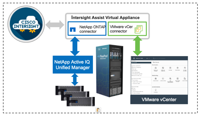
Cisco Intersight Assist device connector for VMware vCenter and NetApp ONTAP
Cisco Intersight integrates with VMware vCenter and NetApp storage as follows: - Cisco Intersight uses the device connector running within Cisco Intersight Assist virtual appliance to communicate with the VMware vCenter. - Cisco Intersight uses the device connector running within a Cisco Intersight Assist virtual appliance to integrate with NetApp Active IQ Unified Manager. The NetApp AFF A400 should be added to NetApp Active IQ Unified Manager.
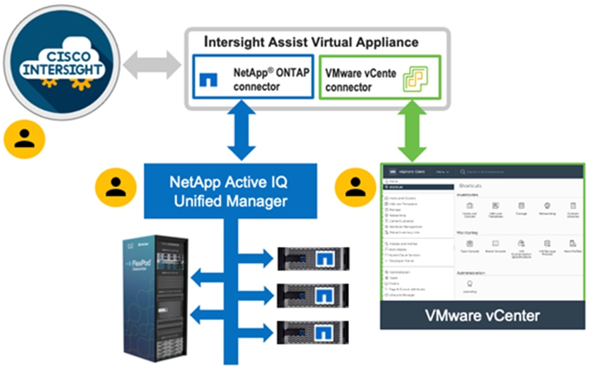
The device connector provides a secure way for connected targets to send information and receive control instructions from the Cisco Intersight portal using a secure internet connection. The integration brings the full value and simplicity of Cisco Intersight infrastructure management service to VMware hypervisor and ONTAP data storage environments.
Enterprise SAN and NAS workloads can benefit equally from the integrated management solution. The integration architecture enables FlexPod customers to use new management capabilities with no compromise in their existing VMware or ONTAP operations. IT users will be able to manage heterogeneous infrastructure from a centralized Cisco Intersight portal. At the same time, the IT staff can continue to use VMware vCenter and NetApp Active IQ Unified Manager for comprehensive analysis, diagnostics, and reporting of virtual and storage environments. The functionality provided through this integration is covered in the upcoming solution design section.
The FlexPod Datacenter with Cisco UCS X-Series and Intersight for Epic EHR solution delivers a cloud-managed infrastructure solution on the latest Cisco UCS hardware. VMware vSphere 7.0 U3 hypervisor is installed on the Cisco UCS X210c M6 Compute Nodes configured for stateless compute design using boot from SAN. Additionally, Local Boot (m.2 MRAID) options are provided. NetApp AFF A400 provides the storage infrastructure required for setting up the VMware environment. The Cisco Intersight cloud-management platform is utilized to configure and manage the infrastructure. The solution requirements and design details are explained in this section.
This document does not replace deployment guidance from Epic, Cisco, or NetApp. This CVD will give instructions on how to deploy the hardware to implement the infrastructure that Epic has developed for your specific requirements. In all cases, follow the guidance given from Epic, Cisco, and NetApp.
Requirements
The FlexPod Datacenter with Cisco UCS X-Series and Intersight for Epic EHR design meets the following general design requirements:
● Resilient design across all layers of the infrastructure with no single point of failure
● Scalable design with the flexibility to add compute capacity, storage, or network bandwidth as needed
● Modular design that can be replicated to expand and grow as the needs of the business grow
● Simplified design with ability to integrate and automate with external automation tools
● Cloud-enabled design which can be configured, managed, and orchestrated from the cloud using GUI or APIs
FlexPod Datacenter with Cisco UCS X-Series supports both IP and Fibre Channel (FC)—based storage access design. For the FC designs, NetApp AFF A400 and Cisco UCS X-Series are connected through Cisco MDS 9132T Fibre Channel Switches and boot from SAN uses the FC network. In this design, VMware ESXi hosts access the VM datastore volumes on NetApp using NFS. The Epic VMs access CIFs shares. The physical connectivity details FC designs are explained below.
FC-based Storage Access: FC, NFS, and CIFS
The physical topology for the FC, NFS, and CIFS based FlexPod Datacenter is shown in Figure 16.
To validate the FC-based storage access in a FlexPod configuration, the components are set up as follows:
● Cisco UCS 6454 Fabric Interconnects provide the chassis and network connectivity.
● The Cisco UCS X9508 Chassis connects to fabric interconnects using Cisco UCS X9108-25G Intelligent Fabric Modules (IFMs), where four 25 Gigabit Ethernet ports are used on each IFM to connect to the appropriate FI.
● Cisco UCS X210c M6 Compute Nodes contain fourth-generation Cisco 14425 virtual interface cards.
● Cisco Nexus 93180YC-FX3 Switches in Cisco NX-OS mode provide the switching fabric.
● Cisco UCS 6454 Fabric Interconnect 100 Gigabit Ethernet uplink ports connect to Cisco Nexus 93180YC-FX3 Switches in a vPC configuration.
● The NetApp AFF A400 controller connects to the Cisco Nexus 93180YC-FX3 Switches using four 25 GE ports from each controller configured as a vPC for NFS traffic.
● Cisco UCS 6454 Fabric Interconnects are connected to the Cisco MDS 9132T switches using 32-Gbps Fibre Channel connections configured as a single port channel for SAN connectivity.
● The NetApp AFF controller connects to the Cisco MDS 9132T switches using 32-Gbps Fibre Channel connections for SAN connectivity.
● VMware 7.0 U3 ESXi software is installed on Cisco UCS X210c M6 Compute Nodes to validate the infrastructure.
Table 1 lists VLANs configured for setting up the FlexPod environment along with their usage.
| VLAN ID |
Name |
Usage |
| 2 |
Native-VLAN |
Use VLAN 2 as native VLAN instead of default VLAN (1). |
| 40 |
OOB-MGMT-VLAN |
Out-of-band management VLAN to connect management ports for various devices |
| 41 |
IB-MGMT-VLAN |
In-band management VLAN utilized for all in-band management connectivity - for example, ESXi hosts, VM management, and so on. |
| 44 |
VM-Traffic |
VM data traffic VLAN |
| 42 |
NFS-VLAN |
NFS VLAN for mounting datastores in ESXi servers for VMs |
| 43 |
vMotion |
VMware vMotion traffic |
| 45 |
CIFS |
VLAN for CIFs shares |
Some of the key highlights of VLAN usage are as follows:
● VLAN 40 allows customers to manage and access out-of-band management interfaces of various devices.
● VLAN 41 is used for in-band management of VMs, ESXi hosts, and other infrastructure services
● VLAN 42 provides ESXi hosts access to the NSF datastores hosted on the NetApp Controllers for deploying VMs.
● VLAN 45 provides virtual machines access to the CIFS shares
In FlexPod Datacenter deployments, each Cisco UCS server equipped with a Cisco Virtual Interface Card (VIC) is configured for multiple virtual Network Interfaces (vNICs), which appear as standards-compliant PCIe endpoints to the OS. The end-to-end logical connectivity including VLAN/VSAN usage between the server profile for an ESXi host and the storage configuration on NetApp AFF A400 controllers is captured in the following subsections.
Logical Topology for IP-based Storage Access
Figure 17 illustrates the end-to-end connectivity design for IP-based storage access.
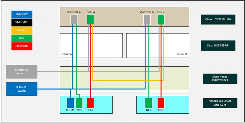
Each ESXi service profile supports:
● Managing the ESXi hosts using a common management segment
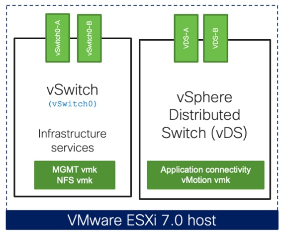
● Four vNICs where:
● Two redundant vNICs (vSwitch0-A and vSwitch0-B) carry management and infrastructure NFS traffic. The MTU value for these vNICs is set as a Jumbo MTU (9000).
● Two redundant vNICs (VDS-A and VDS-B) are used by the vSphere Distributed switch and carry VMware vMotion traffic and customer application data traffic. The MTU for the vNICs is set to Jumbo MTU (9000).
● Each ESXi host (compute node) mounts VM datastores from NetApp AFF A400 controllers using NFS for deploying virtual machines.
Logical Topology for FC-based Storage Access
Figure 18 illustrates the end-to-end connectivity design for FC-based storage access.
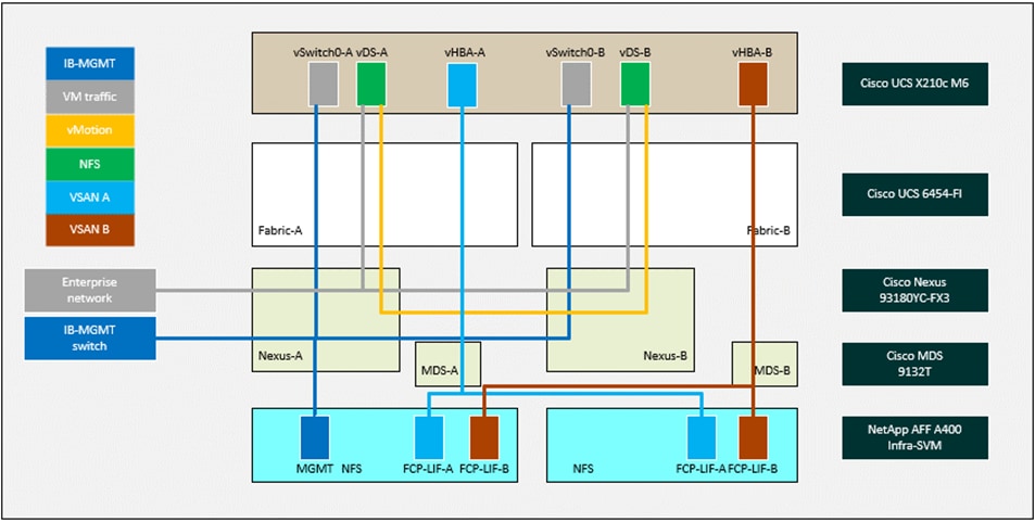
Each ESXi server profile supports:
● Managing the ESXi hosts using a common management segment
● Diskless SAN boot using FC with persistent operating system installation for true stateless computing
● Or: Local boot utilizing M.2 MRAID Adapters
● Four vNICs where:
◦ Two redundant vNICs (vSwitch0-A and vSwitch0-B) carry in-band management, and Infrastructure NFS VLANs. The MTU value for these vNICs is set as a Jumbo MTU (9000).
◦ Two redundant vNICs (VDS-A and VDS-B) are used by the vSphere Distributed switch and carry VMware vMotion traffic and customer application data traffic. The MTU for the vNICs is set to Jumbo MTU (9000).
◦ One vHBA defined on Fabric A to provide access to SAN-A path.
◦ One vHBA defined on Fabric B to provide access to SAN-B path.
● Each ESXi host (compute node) mounts VM datastores from NetApp AFF A400 controllers using NFS for deploying virtual machines.
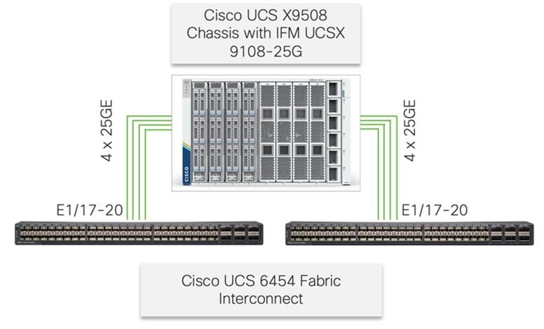
The Cisco UCS X9508 Chassis is equipped with the Cisco UCS X9108-25G intelligent fabric modules (IFMs). The Cisco UCS X9508 Chassis connects to each Cisco UCS 6454 FI using four 25GE ports, as shown in Figure 19. If customers require more bandwidth, all eight ports on the IFMs can be connected to each FI.
Cisco Nexus Ethernet Connectivity
The Cisco Nexus 93180YC-FX3 device configuration covers the core networking requirements for Layer 2 and Layer 3 communication. Some of the key NX-OS features implemented within the design are:
● Feature interface-vans – Allows for VLAN IP interfaces to be configured within the switch as gateways.
● Feature HSRP – Allows for Hot Standby Routing Protocol configuration for high availability.
● Feature LACP – Allows for the utilization of Link Aggregation Control Protocol (802.3ad) by the port channels configured on the switch.
● Feature VPC – Virtual Port-Channel (vPC) presents the two Nexus switches as a single “logical” port channel to the connecting upstream or downstream device.
● Feature LLDP - Link Layer Discovery Protocol (LLDP), a vendor-neutral device discovery protocol, allows the discovery of both Cisco devices and devices from other sources.
● Feature NX-API – NX-API improves the accessibility of CLI by making it available outside of the switch by using HTTP/HTTPS. This feature helps with configuring the Cisco Nexus switch remotely using the automation framework.
● Feature UDLD – Enables unidirectional link detection for various interfaces.
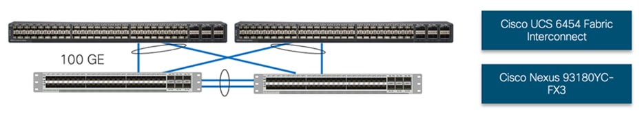
Cisco UCS Fabric Interconnect 6454 Ethernet Connectivity
Cisco UCS 6454 FIs are connected to Cisco Nexus 93180YC-FX3 switches using 100GE connections configured as virtual port channels. Each FI is connected to both Cisco Nexus switches using a 100G connection; additional links can easily be added to the port channel to increase the bandwidth as needed. Figure 20 illustrates the physical connectivity details.
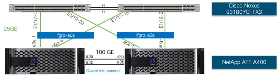
NetApp AFF A400 Ethernet Connectivity
NetApp AFF A400 controllers are connected to Cisco Nexus 93180YC-FX3 switches using 25GE connections configured as virtual port channels. The storage controllers are deployed in a switchless cluster configuration and are connected to each other using the 100GE ports e3a and e3b. Figure 21 illustrates the physical connectivity details.
In Figure 21, the two storage controllers in the high-availability pair are drawn separately for clarity. Physically, the two controllers exist within a single chassis.
Cisco MDS SAN Connectivity – Fibre Channel Design Only
The Cisco MDS 9132T is the key design component bringing together the 32Gbps Fibre Channel (FC) capabilities to the FlexPod design. A redundant 32 Gbps Fibre Channel SAN configuration is deployed utilizing two MDS 9132Ts switches. Some of the key MDS features implemented within the design are:
● Feature NPIV – N port identifier virtualization (NPIV) provides a means to assign multiple FC IDs to a single N port.
● Feature fport-channel-trunk – F-port-channel-trunks allow for the fabric logins from the NPV switch to be virtualized over the port channel. This provides nondisruptive redundancy should individual member links fail.
● Smart-Zoning – a feature that reduces the number of TCAM entries by identifying the initiators and targets in the environment.
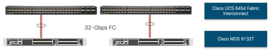
Cisco UCS Fabric Interconnect 6454 SAN Connectivity
For SAN connectivity, each Cisco UCS 6454 Fabric Interconnect is connected to a Cisco MDS 9132T SAN switch using 2 x 32G Fibre Channel port-channel connection, as shown in Figure 22.
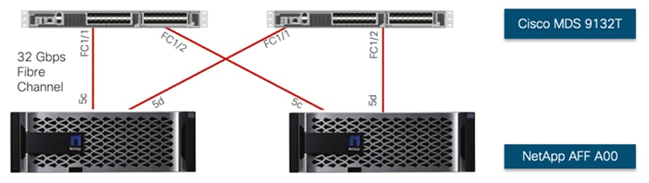
NetApp AFF A400 SAN Connectivity
For SAN connectivity, each NetApp AFF A400 controller is connected to both of Cisco MDS 9132T SAN switches using 32G Fibre Channel connections, as shown in Figure 23.
In Figure 23, the two storage controllers in the high-availability pair are drawn separately for clarity. Physically, the two controllers exist within a single chassis.
Cisco UCS X-Series Configuration - Cisco Intersight Managed Mode
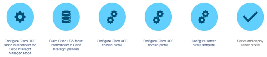
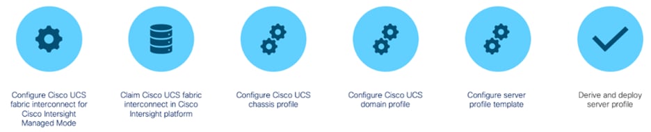
Cisco Intersight Managed Mode standardizes policy and operation management for Cisco UCS X-Series. The compute nodes in Cisco UCS X-Series are configured using server profiles defined in Cisco Intersight. These server profiles derive all the server characteristics from various policies and templates. At a high level, configuring Cisco UCS using Intersight Managed Mode consists of the steps shown in Figure 24.
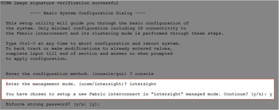
Set up Cisco UCS Fabric Interconnect for Cisco Intersight Managed Mode
During the initial configuration, for the management mode the configuration wizard enables customers to choose whether to manage the fabric interconnect through Cisco UCS Manager or the Cisco Intersight platform. Customers can switch the management mode for the fabric interconnects between Cisco Intersight and Cisco UCS Manager at any time; however, Cisco UCS FIs must be set up in Intersight Managed Mode (IMM) for configuring the Cisco UCS X-Series system. Figure 25 shows the dialog during initial configuration of Cisco UCS FIs for setting up IMM.
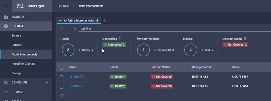
Claim a Cisco UCS Fabric Interconnect in the Cisco Intersight Platform
After setting up the Cisco UCS fabric interconnect for Cisco Intersight Managed Mode, FIs can be claimed to a new or an existing Cisco Intersight account. When a Cisco UCS fabric interconnect is successfully added to the Cisco Intersight platform, all future configuration steps are completed in the Cisco Intersight portal.
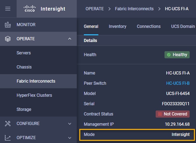
Customers can verify whether a Cisco UCS fabric interconnect is in Cisco UCS Manager managed mode or Cisco Intersight Managed Mode by clicking on the fabric interconnect name and looking at the detailed information screen for the FI, as shown in Figure 27.
A Cisco UCS Chassis profile configures and associate chassis policy to an IMM claimed chassis. The chassis profile feature is available in Intersight only if customers have installed the Intersight Essentials License. The chassis-related policies can be attached to the profile either at the time of creation or later.
The chassis profile in a FlexPod is used to set the power policy for the chassis. By default, Cisco UCS X-Series power supplies are configured in GRID mode, but the power policy can be utilized to set the power supplies in non-redundant or N+1/N+2 redundant modes.
A Cisco UCS domain profile configures a fabric interconnect pair through reusable policies, allows configuration of the ports and port channels, and configures the VLANs and VSANs to be used in the network. It defines the characteristics of and configures the ports on the fabric interconnects. One Cisco UCS domain profile can be assigned to one fabric interconnect domain, and the Cisco Intersight platform supports the attachment of one port policy per Cisco UCS domain profile.
Some of the characteristics of the Cisco UCS domain profile in the FlexPod environment are:
● A single domain profile is created for the pair of Cisco UCS fabric interconnects.
● Unique port policies are defined for the two fabric interconnects.
● The VLAN configuration policy is common to the fabric interconnect pair because both fabric interconnects are configured for same set of VLANs.
● The VSAN configuration policies (FC connectivity option) are unique for the two fabric interconnects because the VSANs are unique.
● The Network Time Protocol (NTP), network connectivity, and system Quality-of-Service (QoS) policies are common to the fabric interconnect pair.
After the Cisco UCS domain profile has been successfully created and deployed, the policies including the port policies are pushed to Cisco UCS fabric interconnects. Cisco UCS domain profile can easily be cloned to install additional Cisco UCS systems. When cloning the UCS domain profile, the new UCS domains utilize the existing policies for consistent deployment of additional Cisco UCS systems at scale.
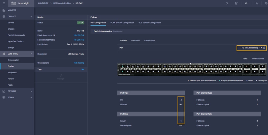
The Cisco UCS X9508 Chassis and Cisco UCS X210c M6 Compute Nodes are automatically discovered when the ports are successfully configured using the domain profile as shown in Figure 29, Figure 30, and Figure 31.
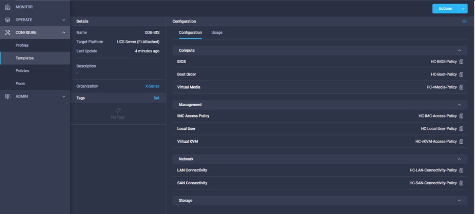
A server profile template enables resource management by simplifying policy alignment and server configuration. A server profile template is created using the server profile template wizard. The server profile template wizard groups the server policies into the following four categories to provide a quick summary view of the policies that are attached to a profile:
● Compute policies: BIOS, boot order, and virtual media policies
● Network policies: adapter configuration, LAN connectivity, and SAN connectivity policies
◦ The LAN connectivity policy requires you to create Ethernet network policy, Ethernet adapter policy, and Ethernet QoS policy.
◦ The SAN connectivity policy requires you to create Fibre Channel (FC) network policy, Fibre Channel adapter policy, and Fibre Channel QoS policy. SAN connectivity policy is only required for the FC connectivity option.
● Storage policies: not used in FlexPod
● Management policies: device connector, Intelligent Platform Management Interface (IPMI) over LAN, Lightweight Directory Access Protocol (LDAP), local user, network connectivity, Simple Mail Transfer Protocol (SMTP), Simple Network Management Protocol (SNMP), Secure Shell (SSH), Serial over LAN (SOL), syslog, and virtual Keyboard, Video, and Mouse (KVM) policies
Some of the characteristics of the server profile template for FlexPod are as follows:
● BIOS policy is created to specify various server parameters in accordance with FlexPod best practices.
● Boot order policy defines virtual media (KVM mapper DVD), all SAN paths for NetApp iSCSI or Fibre Channel logical interfaces (LIFs), and UEFI Shell.
● IMC access policy defines the management IP address pool for KVM access.
● Local user policy is used to enable KVM-based user access.
● For the iSCSI boot from SAN configuration, LAN connectivity policy is used to create six virtual network interface cards (vNICs) — two for management virtual switch (vSwitch0), two for application Virtual Distributed Switch (VDS), and one each for iSCSI A/B vSwitches. Various policies and pools are also created for the vNIC configuration.
● For the FC boot from SAN configuration, LAN connectivity policy is used to create four virtual network interface cards (vNICs) — two for management virtual switches (vSwitch0) and two for application Virtual Distributed Switch (VDS) — along with various policies and pools.
● For the FC connectivity option, SAN connectivity policy is used to create two virtual host bus adapters (vHBAs) — one for SAN A and one for SAN B — along with various policies and pools. The SAN connectivity policy is not required for iSCSI setup.
Figure 32 shows various policies associated with the server profile template.
Derive and Deploy Server Profiles from the Cisco Intersight Server Profile Template
The Cisco Intersight server profile allows server configurations to be deployed directly on the compute nodes based on polices defined in the server profile template. After a server profile template has been successfully created, server profiles can be derived from the template and associated with the Cisco UCS X210c M6 Compute Nodes, as shown in Figure 33.
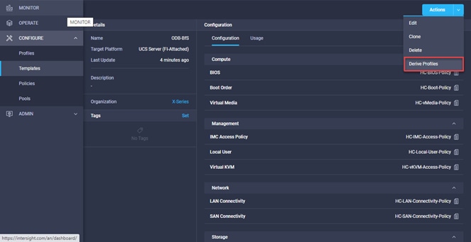
On successful deployment of the server profile, the Cisco UCS X210c M6 Compute Nodes are configured with parameters defined in the server profile and can boot from the storage LUN hosted on NetApp AFF A400.
NetApp AFF A400 – Storage Virtual Machine (SVM) Design
To provide the necessary data segregation and management, a dedicated SVM, Infra-SVM, is created for hosting the Epic environment. The SVM contains the following volumes and logical interfaces (LIFs):
● Volumes
◦ ESXi boot LUNs used to enable ESXi host boot from SAN functionality using FC
◦ Infrastructure datastores used by the vSphere environment to store the VMs and swap files
● Logical interfaces (LIFs)
◦ NFS LIFs to mount NFS datastores in the vSphere environment
◦ FC LIFs for supporting FC Boot-from-SAN traffic
◦ CIFS LIFs to mount CIFS shares in the vSphere environment
Storage Consolidation
Combining Epic NAS and SAN workloads on the same all-flash array is supported and recommended to simplify data management having a single storage platform. This allows you to use a single data management strategy for all workloads regardless of access protocol.
Performance and Scale
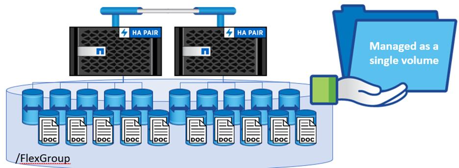
WebBLOB is typically made up of lots of small files with documents and images exported from the production Iris ODB database. Depending on what document management application is used, WebBLOB can grow to hundreds of millions of files. High file count can impact metadata processing and frequently causing outage.
FlexGroups scales performance, metadata processing and capacity using multiple volumes across the entire cluster to up to 24 nodes. A single names space that scales to >20PB and >400 billion files. FlexGroups illuminates any issues with scale with high file count resulting in higher availability. NetApp recommends using FlexGroups for WebBLOB and other critical shares like homedir and profiles that make up an Epic environment. FlexGroups is built into ONTAP and recommended by NetApp.
Reduce Cost
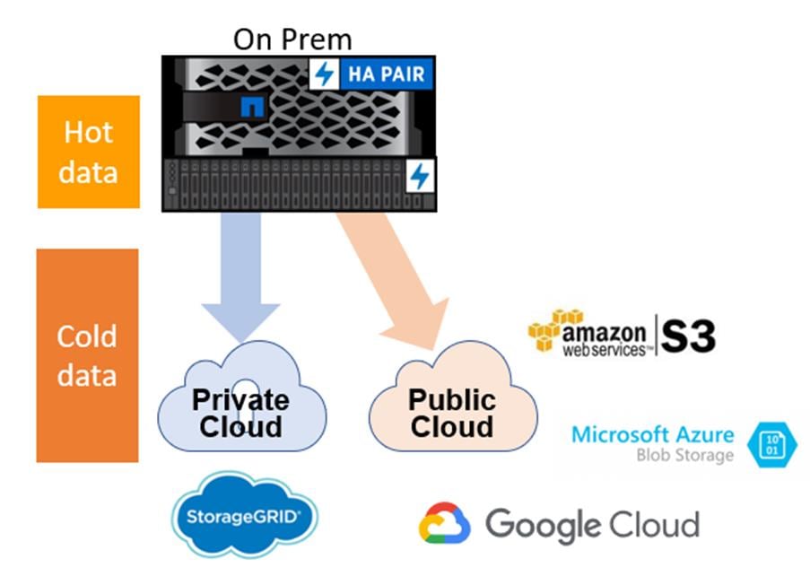
WebBLOB is ~95% cold data and a low performing tier and does not have to be deployed on all flash. NetApp offers options to reduce the cost of NAS while delivering on performance and capability with several options:
● FAS using optimized read and write FlashPool SSD’s is an excellent solution for NAS. FAS and AFF systems can be part of the same cluster. FlashPool is built into ONTAP and recommended by NetApp when using FAS.
● NAS deployed on all-flash and automatically tier backups and cold data to object storage on-premises or in the cloud using the FabricPool feature. All of which can be accomplished without any noticeable performance effect. You can generate a cold data report to review how cold your data is before enabling automatic tiering. You can customize the age of the data to tier through a policy. Epic customers have realized significant savings with this feature. FabricPool is built into ONTAP and optionally used to reduce cost.
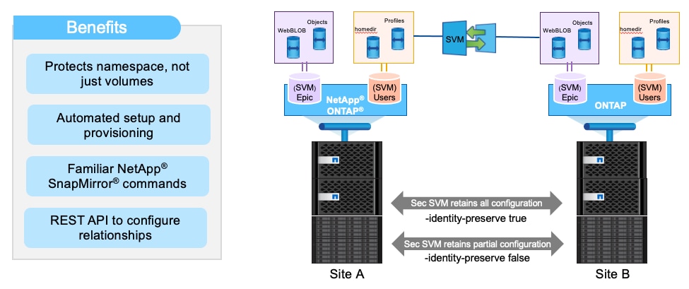
Disaster Recovery Options
ONTAP offers many levels of RPO, and RTO as shown below. At a minimum, the NAS solution should use async replication to DR every 15 minutes and the ability to failover quickly. This can be done by enabling SnapMirror. Since ONTAP controls the writes to storage for NAS, each snapshot is application consistent. Breaking the SnapMirror makes the DR read only copy writable. Sync replication is available but not required and not recommended for WebBLOB because of higher cost of disk.
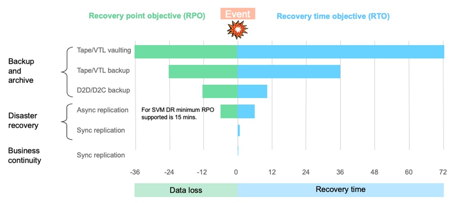
To understand the simplification of NAS DR failover, see Figure 37.
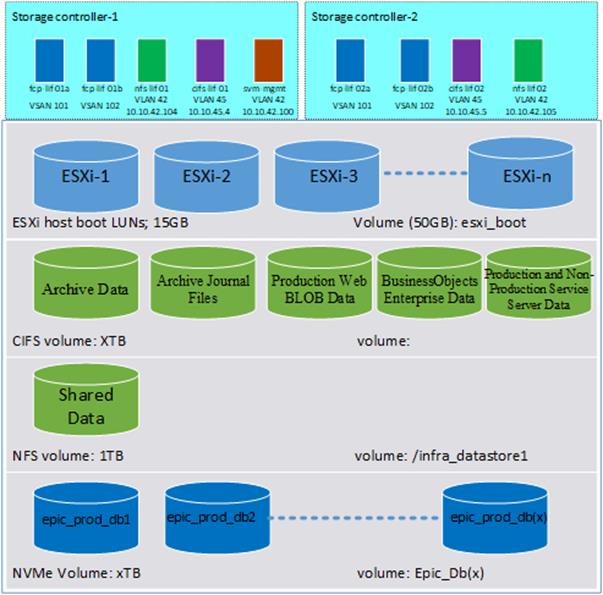
Details on volumes, VLANs, and logical interfaces (LIFs) are shown in Figure 38 for FC connectivity.
Multiple vNICs (and vHBAs) are created for the ESXi hosts using the Cisco Intersight server profile and are then assigned to specific virtual and distributed switches. The vNIC and vHBA distribution for the ESXi hosts is as follows:
● Two vNICs (one on each fabric) for vSwitch0 to support core services such as management and NFS traffic.
● Two vNICs (one on each fabric) for vSphere Virtual Distributed Switch (VDS) to support customer data traffic and vMotion traffic.
● One vHBA each for Fabric-A and Fabric-B for FC stateless boot and datastore access. Figure 39 shows the ESXi vNIC configurations in detail.
Cisco Intersight Integration with VMware vCenter and NetApp Storage
Cisco Intersight works with NetApp’s ONTAP storage and VMware vCenter using third-party device connectors. Since third-party infrastructure does not contain any built-in Intersight device connector, Cisco Intersight Assist virtual appliance enables Cisco Intersight to communicate with non-Cisco devices.
Note: A single Cisco Intersight Assist virtual appliance can support both NetApp ONTAP storage and VMware vCenter.
Cisco Intersight integration with VMware vCenter and NetApp ONTAP enables customers to perform following tasks right from the Intersight dashboard:
● Monitor the virtualization and storage environment.
● Add various dashboard widgets to obtain useful at-a-glance information.
● Perform common Virtual Machine tasks such as power on/off, remote console and so on.
● Orchestrate virtual and storage environment to perform common configuration tasks.
● Orchestrate NetApp ONTAP storage tasks to setup a Storage Virtual Machine and provide NAS and SAN services.
The following sections explain the details of these operations. Since Cisco Intersight is a SaaS platform, the monitoring and orchestration capabilities are constantly being added and delivered seamlessly from the cloud.
Note: The monitoring capabilities and orchestration tasks and workflows listed below provide an in-time snapshot for your reference. For the most up to date list of capabilities and features, customers should use the help and search capabilities in Cisco Intersight.
To integrate and view various NetApp storage and VMware vCenter parameters from Cisco Intersight, a Cisco Intersight Advantage license is required. To use Cisco Intersight orchestration and workflows to provision the storage and virtual environments, an Intersight Premier license is required.
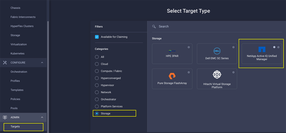
Integrate Cisco Intersight with NetApp ONTAP Storage
To integrate NetApp AFF A400 with Cisco Intersight, customers need to deploy:
● Cisco Intersight Assist virtual appliance
● NetApp Active IQ Unified Manager virtual appliance
Using the Cisco Intersight Assist, NetApp Active IQ Unified Manager is claimed as a target in Cisco Intersight, as shown in Figure 41.
Obtain Storage-level Information
After successfully claiming the NetApp Active IQ Unified Manager as a target, customers can view storage-level information in Cisco Intersight if they have already added NetApp AFF A400 to the NetApp Active IQ Unified Manager.
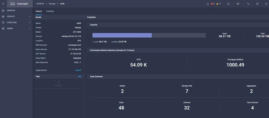
Table 2 lists some of the core NetApp AFF A400 information presented through Cisco Intersight.
Table 2. NetApp Storage Information in Cisco Intersight
| Category |
Name |
Detail |
| General |
Name |
Name of the controller |
| Vendor |
NetApp |
|
| Model |
NetApp AFF model information (for example, AFF-A400) |
|
| Version |
Software version |
|
| Monitoring |
Capacity |
Total, used, and available system capacity |
|
|
Summary of Nodes, Storage VMs, Aggregates, disks and so on. in the system |
|
| Inventory |
Volumes |
Volumes defined in the system and their status, size, usage, and configured export policies |
| LUNs |
LUNs defined in the system and their status, size, usage, and mapped iGroups |
|
| Aggregates |
Configured aggregates and their status, size, usage, and space savings |
|
| Storage VMs |
Storage VM (SVM) information, state, allowed protocols, and logical ethernet and fibre channel interface details. |
|
| Export policies |
Export policies defined in the system and the associated SVMs |
|
| SAN initiator groups |
SAN initiator groups, their type, protocol, initiator information, and associated SVMs |
|
| Licenses |
Licenses installed on the system |
|
| Nodes |
Controller information, such as model, OS, serial number, and so on. |
|
| Disks |
Disk information, including type, model, size, node information, status of the disks, and aggregate details |
|
| Ports |
Ethernet and FC ports configured on the system |
Storage Widget in the Dashboard
Customers can also add the storage dashboard widgets to Cisco Intersight for viewing NetApp AFF A400 at a glance information on the Cisco Intersight dashboard, as shown in Figure 43.
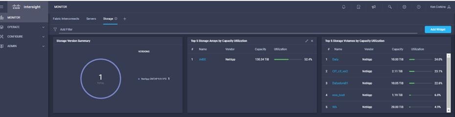
These storage widgets provide useful information such as:
● Storage arrays and capacity utilization
● Top-five storage volumes by capacity utilization
● Storage versions summary, providing information about the software version and the number of storage systems running that version
Cisco Intersight Orchestrator – NetApp ONTAP Storage
Cisco Intersight Orchestrator provides various workflows that can be used to automate storage provisioning. Some of the sample storage workflows available for NetApp ONTAP storage are listed in Table 3.
Table 3. NetApp ONTAP Storage Workflows in Cisco Intersight Orchestrator
| Name |
Details |
| New NAS datastore |
Create a NFS storage volume and build NAS datastore on the volume |
| New storage export policy |
Create a storage export policy and add the created policy to a NFS volume |
| New storage host |
Create a new storage host or igroup to enable SAN mapping |
| New storage interface |
Create a storage IP or FC interface |
| New storage virtual machine |
Create a storage virtual machine |
| New VMFS datastore |
Create a storage volume and build a Virtual Machine File System (VMFS) datastore on the volume |
| Remove NAS datastore |
Remove the NAS datastore and the underlying NFS storage volume |
| Remove storage export policy |
Remove the NFS volume and the export policy attached to the volume |
| Remove storage host |
Remove a storage host. If a host group name is provided as input, the workflow will also remove the host from the host group. |
| Remove VMFS datastore |
Remove a VMFS data store and remove the backing volume from the storage device |
| Update NAS datastore |
Update NAS datastore by expanding capacity of the underlying NFS volume |
| Update storage host |
Update the storage host details. If the inputs for a task are provided, then the task is run; otherwise, it is skipped. |
| Update VMFS datastore |
Expand a datastore on the hypervisor manager by extending the backing storage volume to specified capacity, and then expand the data store to use the additional capacity |
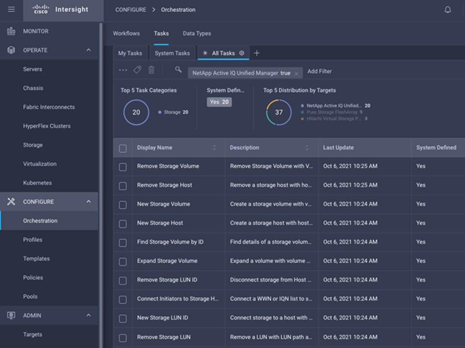
In addition to the above workflows, Cisco Intersight Orchestrator also provides many storage and virtualization tasks for customers to create custom workflow based on their specific needs. A sample subset of these tasks is highlighted in Figure 44.
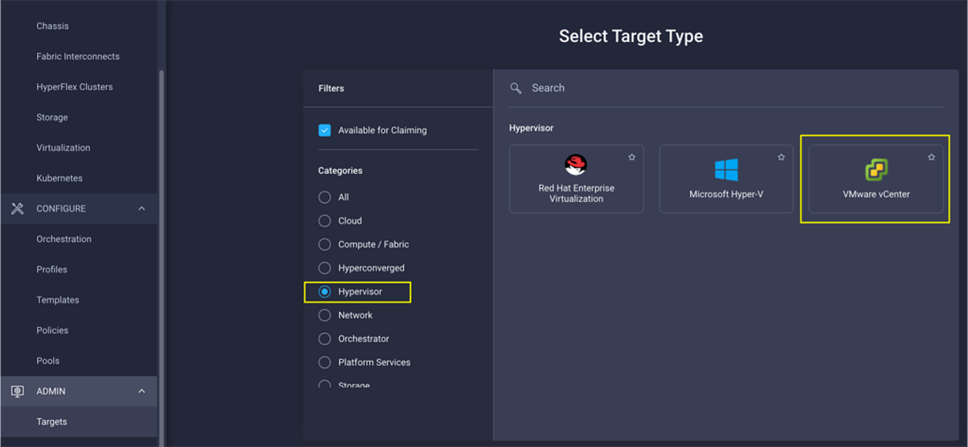
Integrate Cisco Intersight with VMware vCenter
To integrate VMware vCenter with Cisco Intersight, VMware vCenter can be claimed as a target using Cisco Intersight Assist Virtual Appliance, as shown in Figure 45.
Obtain Hypervisor-level Information
After successfully claiming the VMware vCenter as a target, customers can view hypervisor-level information in Cisco Intersight including hosts, VMs, clusters, datastores, and so on.
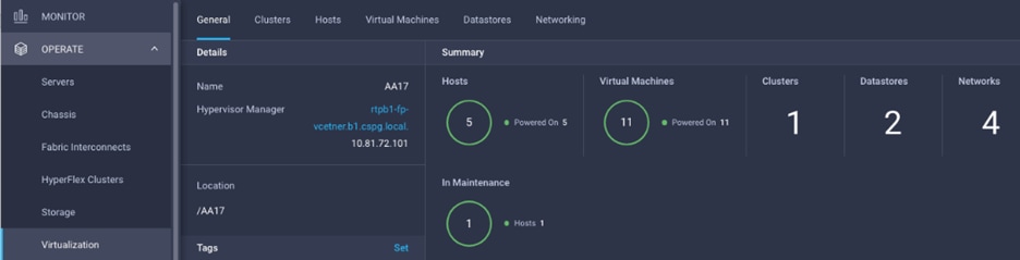
Table 4 lists some of the main virtualization properties presented in Cisco Intersight.
Table 4. Virtualization (VMware vCenter) Information in Cisco Intersight
| Category |
Name |
Details |
| General |
Name |
Name of the data center |
| Hypervisor manager |
Host name or IP address of the vCenter |
|
| Clusters |
Name |
Name of the cluster |
| Data center |
Name of the data center |
|
| Hypervisor type |
ESXi |
|
| Hypervisor manager |
vCenter IP address or the host name |
|
| CPU capacity |
CPU capacity in the cluster (GHz) |
|
| CPU consumed |
CPU cycles consumed by workloads (percentage and GHz) |
|
| Memory capacity |
Total memory in the cluster (GB) |
|
| Memory consumed |
Memory consumed by workloads (percentage and GB) |
|
| Total cores |
All the CPU cores across the CPUs in the cluster |
|
| VMware cluster information allows customers to access additional details about hosts and virtual machines associated with the cluster. |
|
|
| Hosts |
Name |
Host name or IP address |
| Server |
Server profile associated with the ESXi host |
|
| Cluster |
Cluster information if the host is part of a cluster |
|
| Data center |
VMware data center |
|
| Hypervisor type |
ESXi |
|
| Hypervisor manager |
vCenter IP address of host name |
|
| Uptime |
Host uptime |
|
| Virtual Machines |
Number and state of VMs running on a host |
|
| CPU Information |
CPU cores, sockets, vendor, speed, capacity, consumption, and other CPU related information |
|
| Memory Information |
Memory capacity and consumption information |
|
| Hardware Information |
Compute node hardware information such as serial number, model and so on. |
|
| Host information allows customers to access additional details about clusters, VMs, datastores, and networking related to the current ESXi host. |
|
|
| Virtual machines |
Name |
Name of the VM |
| Guest OS |
Operating system, for example, RHEL, CentOS, and so on. |
|
| Hypervisor type |
ESXi |
|
| Host |
ESXi host information for the VM |
|
| Cluster |
VMware cluster name |
|
| Data center |
VMware data center name |
|
| IP address |
IP address(s) assigned to the VM |
|
| Hypervisor manager |
IP address of host name of the vCenter |
|
| Resource Information |
CPU, memory, disk, and network information |
|
| Guest Information |
Hostname, IP address and operating system information |
|
| VM information allows customers to access additional details about clusters, hosts, datastores, networking, and virtual disks related to the current VM. |
|
|
| Datastores |
Name |
Name of the datastore in VMware vCenter |
| Type |
NFS or VMFS and so on. |
|
| Accessible |
Yes, if datastore is accessible; No, if datastore is inaccessible |
|
| Thin provisioning |
Yes, if thin provisioning is allowed; No if thin provisioning is not allowed |
|
| Multiple host access |
Yes, if multiple hosts can mount the datastore; No, if the datastore only allows a single host |
|
| Storage capacity |
Space in GB or TB |
|
| Storage consumes |
Percentage and GB |
|
| Data center |
Name of VMware vCenter data center |
|
| Hypervisor manager |
vCenter hostname or IP address |
|
| Datastore Cluster |
Datastore cluster information if datastore cluster is configured |
|
| Hosts and Virtual Machines |
Number if hosts connected to a datastore and number of VM hosted on the datastore |
|
| Datastore information allows customers to access additional details about hosts and VMs associated with the datastore. |
|
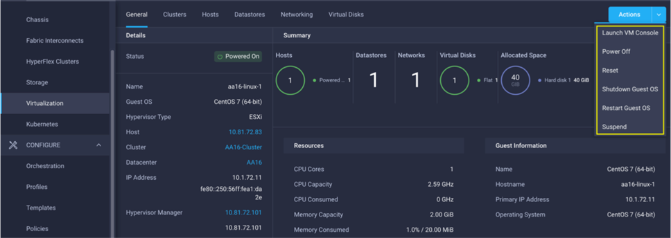
Interact with Virtual Machines
VMware vCenter integration with Cisco Intersight allows customers to directly interact with the virtual machines (VMs) from the Cisco Intersight dashboard. In addition to obtaining in-depth information about a VM, including the operating system, CPU, memory, host name, and IP addresses assigned to the virtual machines, customers can use Intersight to perform following actions on the virtual machines:
● Launch VM console
● Power off
● Reset
● Shutdown guest OS
● Restart guest OS
● Suspend
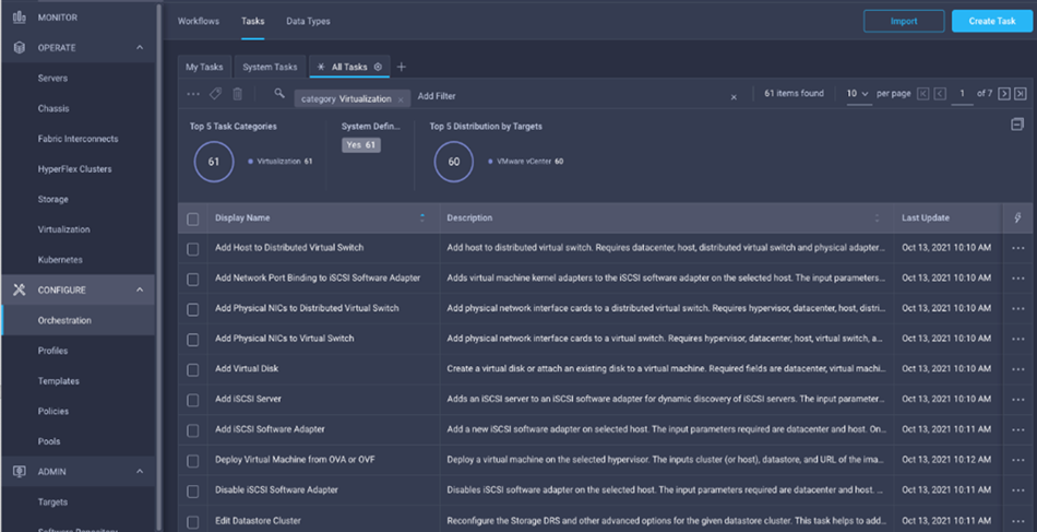
Cisco Intersight Orchestrator – VMware vCenter
Cisco Intersight Orchestrator provides various workflows that can be used for the VM and hypervisor provisioning. Some of the sample workflows available for VMware vCenter are captured in Table 5.
Table 5. VMware vCenter Workflows in Cisco Intersight Orchestrator
| Name |
Details |
| New NAS Datastore |
Create a NFS storage volume and build NAS datastore on the volume. |
| New VMFS Datastore |
Create a storage volume and build VMFS datastore on the volume. |
| New Virtual Machine |
Create a new virtual machine on the hypervisor from an OVA or OVF file. Datastore, Host/Cluster, and Image URL fields are mandatory. All other inputs are optional. |
| Remove NAS Datastore |
Remove the NAS datastore and the underlying NFS storage volume. |
| Remove VMFS Datastore |
Remove VMFS datastore and remove the backing volume from the storage device. |
| Update NAS Datastore |
Update NAS datastore by expanding capacity of the underlying NFS volume. |
| Update VMFS Datastore |
Expand a datastore on hypervisor manager by extending the backing storage volume to specified capacity, and then grow the datastore to utilize the additional capacity. |
In addition to the above workflows, Cisco Intersight Orchestrator provides many tasks for customers to create custom workflows depending on their specific requirements. A sample subset of these tasks is highlighted in Figure 48.
Deployment Hardware and Software
FlexPod is a defined set of hardware and software that serves as an integrated foundation for both virtualized and non-virtualized solutions. VMware vSphere® built on FlexPod includes NetApp AFF storage, Cisco Nexus® networking, Cisco MDS storage networking, the Cisco Unified Computing System (Cisco UCS®), and VMware vSphere software in a single package. The design is flexible enough that the networking, computing, and storage can fit in one data center rack or be deployed according to a customer’s data center design. Port density enables the networking components to accommodate multiple configurations of this kind.
One benefit of the FlexPod architecture is the ability to customize or “flex” the environment to suit a customer’s requirements. A FlexPod can easily be scaled as requirements and demand change. The unit can be scaled both up (adding resources to a FlexPod unit) and out (adding more FlexPod units). The reference architecture detailed in this document highlights the resiliency, cost benefit, and ease of deployment of a Fibre Channel and IP-based storage solution. A storage system capable of serving multiple protocols across a single interface allows for customer choice and investment protection because it truly is a wire-once architecture.
Epic is prescriptive as to its customers’ hardware requirements because of an overarching requirement for delivering predictable low-latency system performance and high availability. FlexPod, a validated, rigorously tested converged infrastructure from the strategic partnership of Cisco and NetApp, is engineered and designed specifically for delivering predictable low-latency system performance and high availability. This approach results in Epic high comfort levels and ultimately the best response time for users of the Epic EHR system. The FlexPod solution from Cisco and NetApp meets Epic system requirements with a high performing, modular, validated, converged, virtualized, efficient, scalable, and cost-effective platform.
Figure 49 shows the VMware vSphere built on FlexPod components and the network connections for a configuration with the Cisco UCS 6454 Fabric Interconnects. This design has port-channeled 25 Gb Ethernet connections between the Cisco UCS X9508 Blade Chassis and the Cisco UCS Fabric Interconnects via the Cisco UCS 9108 25G Intelligent Fabric Modules, and port-channeled 25 Gb Ethernet connections between the Cisco UCS Fabric modules and Cisco Nexus 9000s, and between the Cisco Nexus 9000s and NetApp AFF A400 storage array. This infrastructure option expanded with Cisco MDS switches sitting between the Cisco UCS Fabric Interconnects and the NetApp AFF A400 to provide FC-booted hosts with 32 Gb FC block-level access to shared storage. The reference architecture reinforces the “wire-once” strategy, because as additional storage is added to the architecture, no re-cabling is required from the hosts to the Cisco UCS fabric interconnects.
The reference hardware configuration includes:
● Two Cisco Nexus 93180YC-FX3 switches
● Two Cisco UCS 6454 fabric interconnects
● One Cisco UCS X9508 Chassis
● Two Cisco MDS 9132T multilayer fabric switches
● One NetApp AFF A400 (HA pair) running ONTAP 9.10.1P1 with NVMe SSD disks
Hardware and Software Versions
Table 6 lists the hardware and software revisions for this solution. It is important to note that the validated FlexPod solution explained in this document adheres to Cisco, NetApp, and VMware interoperability matrix to determine support for various software and driver versions. Customers can use the same interoperability matrix to determine support for components that are different from the current validated design.
Click the following links for more information:
● NetApp Interoperability Matrix Tool: http://support.netapp.com/matrix/
● Cisco UCS Hardware and Software Interoperability Tool: http://www.cisco.com/web/techdoc/ucs/interoperability/matrix/matrix.html
● VMware Compatibility Guide: http://www.vmware.com/resources/compatibility/search.php
Table 6. Hardware and Software Revisions
| Compute |
Device |
Image |
Comments |
| Compute |
Cisco UCS X210c M6 Servers |
5.0(1b) |
|
| Cisco UCS Fabric Interconnects 6454 |
9.3(5)I42(1g) |
|
|
| Network |
Cisco Nexus 93180YC-FX3 NX-OS |
9.3(8) |
|
| Cisco MDS 9132T |
8.4(2c) |
|
|
| Storage |
NetApp AFF A400 |
ONTAP 9.10.1P1 |
|
| Software |
Cisco Data Center Network Manager (SAN) |
11.5(1) |
|
| Cisco Intersight Assist Appliance |
1.0.9-342 |
|
|
| VMware vCenter Appliance |
7.0 Update 3 |
|
|
| VMware ESXi |
7.0 U3 |
|
|
| VMware ESXi nfnic FC Driver |
5.0.0.12 |
Supports FC-NVMe |
|
| VMware ESXi nenic Ethernet Driver |
1.0.35.0 |
|
|
| NetApp ONTAP Tools for VMware vSphere |
9.10 |
formerly Virtual Storage Console (VSC) |
|
| NetApp NFS Plug-in for VMware VAAI |
2.0-15 |
|
|
| NetApp SnapCenter for VMware vSphere |
4.6 |
Includes the vSphere plug-in for SnapCenter |
|
| NetApp Active IQ Unified Manager |
9.10P1 |
|
|
| Management |
Cisco Intersight Assist Virtual Appliance |
1.0.9-342 |
|
| NetApp Active IQ |
N/A |
|
Configuration Guidelines
This document explains how to configure a fully redundant, highly available configuration for a FlexPod unit with ONTAP storage. Therefore, reference is made to which component is being configured with each step, either 01 or 02 or A and B. For example, node01 and node02 are used to identify the two NetApp storage controllers that are provisioned with this document, and Cisco Nexus A or Cisco Nexus B identifies the pair of Cisco Nexus switches that are configured. The Cisco UCS Fabric Interconnects are similarly configured. Additionally, this document details the steps for provisioning multiple Cisco UCS hosts, and these examples are identified as: VM-Host-Infra-01, VM-Host-Infra-02 to represent infrastructure hosts deployed to each of the fabric interconnects in this document. Finally, to indicate that you should include information pertinent to your environment in a given step, appears as part of the command structure. See the following example for the network port vlan create command:
Usage:
network port vlan create ?
[-node] <nodename> Node
{ [-vlan-name] {<netport>|<ifgrp>} VLAN Name
| -port {<netport>|<ifgrp>} Associated Network Port
[-vlan-id] <integer> } Network Switch VLAN Identifier
Example:
network port vlan create -node <node01> -vlan-name a0a-<vlan id>
This document is intended to enable you to fully configure the customer environment. In this process, various steps require you to insert customer-specific naming conventions, IP addresses, and VLAN schemes, as well as to record appropriate MAC addresses. Table 7 lists the VLANs necessary for deployment as outlined in this guide.
| VLAN Name |
VLAN Purpose |
ID used in Validating this Document |
Subnet Used in Validating This Document |
Default Gateway used in Validating this Document |
| Native-Vlan |
VLAN to which untagged frames are assigned |
2 |
N/A |
N/A |
| OOB-MGMT |
VLAN for out-of-band management interfaces |
40 |
10.10.40.0/24 |
10.10.40.1 |
| IB-MGMT |
VLAN for in-band management interfaces |
41 |
10.10.41.0/24 |
10.10.41.1 |
| Infra-NFS |
VLAN for Infrastructure NFS traffic |
42 |
10.10.42.0/24 |
10.10.42.1 |
| vMotion |
VLAN for VMware vMotion |
43 |
10.10.43.0/24 |
10.10.43.1 |
| VM-Traffic |
VLAN for Production VM Interfaces |
44 |
10.10.44.0/24 |
10.10.44.1 |
| CIFS-Traffic |
VLAN for CIFS/SMB VM traffic |
45 |
10.10.45.0/24 |
10.10.45.1 |
| FCoE-A |
VLAN for FCoE encapsulation of VSAN-A |
101 |
N/A |
N/A |
| FCoE-B |
VLAN for FCoE encapsulation of VSAN-B |
102 |
N/A |
N/A |
| Virtual Machine Description |
Host Name |
IP Address |
| vCenter Server |
vcenter.hc.cvd |
10.10.40.4 |
| NetApp ONTAP Tools for VMware vSphere |
ontap-tools.hc.cvd |
10.10.40.5 |
| NetApp SnapCenter for VMware vSphere |
scv.hc.cvd |
10.10.40.9 |
| NetApp Active IQ Unified Manager |
aiq.hc.cvd |
10.10.40.7 |
| Cisco Intersight Assist |
intersight.hc.cvd |
10.10.40.8 |
The information in this section is provided as a reference for cabling the physical equipment in a FlexPod environment. To simplify cabling requirements, a cabling diagram was used (see Figure 50).
Figure 50 illustrates the details for the prescribed and supported configuration of the NetApp AFF A400 running NetApp ONTAP 9.10.1.
Note: For any modifications of this prescribed architecture, consult the NetApp Interoperability Matrix Tool (IMT).
This document assumes that out-of-band management ports are plugged into an existing management infrastructure at the deployment site. These interfaces will be used in various configuration steps.
Note: Be sure to use the cabling directions in this section as a guide.
The NetApp storage controller and disk shelves should be connected according to best practices for the specific storage controller and disk shelves. For disk shelf cabling, refer to NetApp Support.
Figure 50 details the cable connections used in the validation lab for the FlexPod topology based on the Cisco UCS 6454 fabric interconnect. Two 32Gb uplinks connect as port-channels to each Cisco UCS Fabric Interconnect from the MDS switches, and a total of four 32Gb links connect the MDS switches to the NetApp AFF controllers. Also, 25Gb links connect the Cisco UCS Fabric Interconnects to the Cisco Nexus Switches and the NetApp AFF controllers to the Cisco Nexus Switches. Additional 1Gb management connections will be needed for an out-of-band network switch that sits apart from the FlexPod infrastructure. Each Cisco UCS fabric interconnect and Cisco Nexus switch is connected to the out-of-band network switch, and each AFF controller has a connection to the out-of-band network switch. Layer 3 network connectivity is required between the Out-of-Band (OOB) and In-Band (IB) Management Subnets.
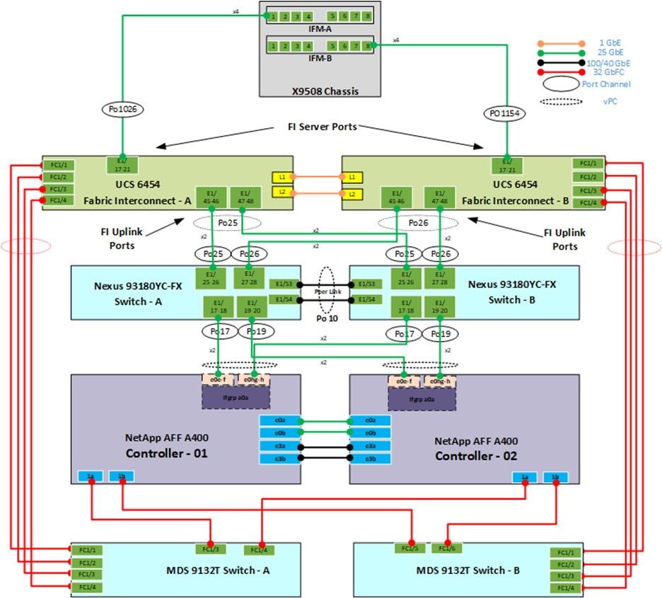
Automation Workflow and Solution Deployment
If using the published Automation scripts (Ansible playbooks and Terraform scripts) to configure the FlexPod infrastructure, complete this section of the document. If completing a manual configuration, skip to section FlexPod Cisco Nexus Switch Manual Configuration.
The Ansible automated FlexPod solution uses a management workstation (control machine) to run Ansible playbooks to configure Cisco Nexus, NetApp ONTAP Storage, Cisco MDS, VMware ESXi and vCenter, NetApp ONTAP Tools, and NetApp Active IQ Unified Manager.
The Terraform automated FlexPod solution uses a management workstation to run the Terraform configuration scripts to configure the Cisco UCS components (UCS Domain and UCS servers).
Figure 51 illustrates the FlexPod solution implementation workflow which is explained in the following sections.
Note: The FlexPod infrastructure layers are configured in the order illustrated.
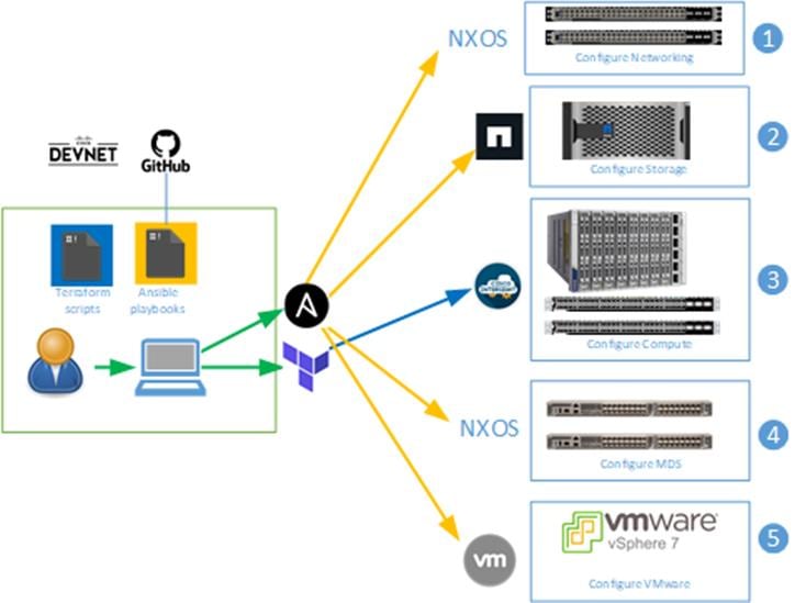
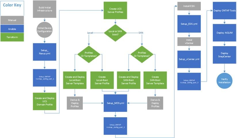
You need to use a GitHub repository from one public location; the first step in the process is to clone the GitHub collection named FlexPod-for-EHR (https://github.com/ucs-compute-solutions/FlexPod-for-EHR.git) to a new empty folder on the management workstation. Cloning the repository creates a local copy, which is then used to run the playbooks that have been created for this solution.
Procedure 1. Clone the GitHub Repository
Step 1. From the management workstation, create a new folder for the project. The GitHub collection will be cloned in a new folder inside this one, named FlexPod-for-EHR.
Step 2. Open a command-line or console interface on the management workstation and change directories to the new folder just created.
Step 3. Clone the GitHub collection using the following command:
git clone https://github.com/ucs-compute-solutions/FlexPod-for-EHR.git
Step 4. Change directories to the new folder named FlexPod-for-EHR.
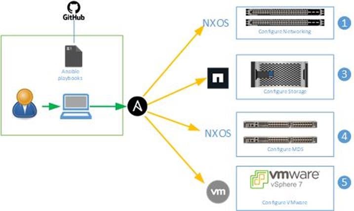
Prerequisites
Setup of the solution begins with a management workstation that has access to the Internet and with a working installation of Ansible. The management workstation commonly runs a variant of Linux or MacOS for ease of use with these command-line-based tools. Instructions for installing the workstation are not included in this document, but basic installation and configuration of Ansible is covered. A guide for getting started with Ansible can be found at the following link:
● Getting Started with Red Hat Ansible: https://www.ansible.com/resources/get-started
● To use the Ansible playbooks demonstrated in this document, the management workstation must also have a working installation of Git and access to the Cisco DevNet public GitHub repository. The Ansible playbooks used in this document are cloned from the public repositories, located at the following links:
◦ Cisco DevNet: https://developer.cisco.com/codeexchange/github/repo/ucs-compute-solutions/FlexPod-for-EHR
◦ GitHub repository: https://github.com/ucs-compute-solutions/FlexPod-for-EHR
● The Cisco Nexus and MDS Switches, NetApp Storage and Cisco UCS must be physically racked, cabled, powered, and configured with management IP addresses before the Ansible-based installation procedure can begin as shown in the cabling diagram Figure 50. If necessary, upgrade the Cisco Nexus Switches to release 9.3(8) and the Cisco UCS Interconnects to 9.3(5)I42(1g) the packages for blades servers set to 5.0(1b).
● Before running each Ansible Playbook to setup the Network, Storage controllers, and VMware ESXi, various variables must be updated based on the customers environment and specific implementation with values such as the VLANs, UCS node WWPNs, IP addresses for NFS interfaces and values needed for VMware ESXi.
Procedure 1. Prepare Management Workstation (Control Machine)
Note: These installation steps are performed on the CentOS management host to prepare the host for solution deployment to support the automation of Cisco Nexus, NetApp Storage, Cisco MDS and VMware ESXi using Ansible Playbooks.
Note: The following steps were performed on a CentOS 8.4 Virtual Machine as the root user.
Step 1. Install EPEL repository on the management host.
dnf install https://dl.fedoraproject.org/pub/epel/epel-release-latest-8.noarch.rpm
Step 2. Install Ansible engine.
dnf install ansible
Step 3. Verify Ansible version to make sure it is release 2.9 or later.
ansible --version
ansible 2.9.23
config file = /etc/ansible/ansible.cfg
configured module search path = ['/root/.ansible/plugins/modules', '/usr/share/ansible/plugins/modules']
ansible python module location =
/usr/lib/python3.6/site-packages/ansible
executable location = /usr/bin/ansible
python version = 3.6.8 (default, Mar 19 2021, 08:58:41) [GCC 8.4.1 20200928 (Red Hat 8.4.1-1)]
Step 4. Install NetApp specific python modules.
pip3 install netapp-lib
Step 5. Install ansible-galaxy collections for Cisco Nexus, NetApp ONTAP, and VMware as follows:
ansible-galaxy collection install cisco.nxos
ansible-galaxy collection install netapp.ontap
ansible-galaxy collection install community.vmware
Step 6. Optional: These collections can also be automatically installed using the requirements.yml file in the root of the Ansible repository with the command:
ansible-galaxy collection install -r requirements.yml
Terraform
Terraform is an open-source infrastructure as code software tool that enables you to create, change, and improve infrastructure safely and predictably.
Terraform helps with:
● Increased agility with reduced time to provision from weeks to minutes with automated workflow
● Control costs systematically as users and applications scale
● Reduce risk and discover errors before they happen with code reviews and embed provisioning guardrails
Providers are plugins that implement resource types likes Intersight. Terraform CLI finds and installs providers when initializing a working directory. It can automatically download providers from a Terraform registry or load them from a local mirror or cache.
Why Terraform provider for the Cisco Intersight?
The Cisco Intersight platform supports the Terraform provider. The Terraform provider allows organizations to develop Cisco Intersight resources as self-service infrastructure using code rather than manual provisioning. This approach provides several benefits:
● You can more quickly and easily scale Cisco Intersight resources. You can provision infrastructure in minutes, with little effort, using the automated workflows, performing the same tasks that used to take days.
● The operating model of Terraform is well suited for the Cisco Intersight platform, because it accommodates the shift from static to dynamic infrastructure provisioning. For example, if a resource is deleted in the Terraform configuration, it will be reflected in the Cisco Intersight platform when the new configuration is applied.
● Terraform maintains a state file, which is a record of the currently provisioned resources. State files provide a version history of Cisco Intersight resources, enabling a detailed audit trail of changes.
● The provider enables idempotency, producing the same result and state with repeated API calls.
● The set of files used to describe infrastructure in Terraform is known as a Terraform configuration. The configuration is written using HashiCorp Configuration Language (HCL), a simple human-readable configuration language, to define a desired topology of infrastructure resources.
Setup of the solution begins with a management workstation that has access to the Internet and with a working installation of Terraform. The management workstation commonly runs a variant of Windows, Linux or MacOS for ease of use with these command-line-based tools. Instructions for installing the workstation are not included in this document, but basic installation and configuration of Terraform is covered.
● Introduction to Terraform: https://www.terraform.io/intro/index.html
● To use the Terraform scripts demonstrated in this document, the management workstation must also have a working installation of Git and access to the Cisco DevNet public GitHub repository. The Terraform scripts used in this document are cloned from the public repositories, located at the following links:
◦ Cisco DevNet: https://developer.cisco.com/codeexchange/explore/#search=ucs-compute-solutions
◦ GitHub repository: https://github.com/ucs-compute-solutions/FlexPod-for-EHR
● The Cisco UCS must be physically racked, cabled, powered, and configured with management IP addresses before the Terraform-based installation procedure can begin as shown in the cabling diagram (Figure 50).
● If necessary, upgrade the Cisco 6454 Fabric Interconnects to release 9.3(5)I42(1g) and the Cisco UCS Fabric Interconnects to 4.2(1f) with the firmware packages for blades servers set to 5.0(1b).
● Before running each Terraform script to setup the Cisco UCS, various variables have to be updated based on the customers environment and specific implementation with values such as the VLANs, pools and ports on Cisco UCS, IP addresses for NFS and iSCSI interfaces and values needed for VMware ESXi.
Prepare Management Workstation (Control Machine)
Instructions for installing Terraform on Windows, Linux or MacOS can be found at this link; https://learn.hashicorp.com/tutorials/terraform/install-cli
Verify that the installation worked by opening a new terminal session and listing Terraform’s available subcommands:
> terraform -help
Usage: terraform [global options] <subcommand> [args]
The available commands for execution are listed below.
The primary workflow commands are given first, followed by
less common or more advanced commands.
Main commands:
init Prepare your working directory for other commands
validate Check whether the configuration is valid
plan Show changes required by the current configuration
apply Create or update infrastructure
destroy Destroy previously-created infrastructure
All other commands:
console Try Terraform expressions at an interactive command prompt
fmt Reformat your configuration in the standard style
force-unlock Release a stuck lock on the current workspace
get Install or upgrade remote Terraform modules
graph Generate a Graphviz graph of the steps in an operation
import Associate existing infrastructure with a Terraform resource
login Obtain and save credentials for a remote host
logout Remove locally-stored credentials for a remote host
output Show output values from your root module
providers Show the providers required for this configuration
refresh Update the state to match remote systems
show Show the current state or a saved plan
state Advanced state management
taint Mark a resource instance as not fully functional
test Experimental support for module integration testing
untaint Remove the 'tainted' state from a resource instance
version Show the current Terraform version
workspace Workspace management
Global options (use these before the subcommand, if any):
-chdir=DIR Switch to a different working directory before executing the
given subcommand.
-help Show this help output, or the help for a specified subcommand.
-version An alias for the "version" subcommand.
Terraform Provider Configuration
Each of the subdirectories for these steps include a main.tf file which is used to configure the providers Terraform uses to authenticate to Cisco Intersight. This is accomplished using API keys that must be created and saved for use within all four steps of this procedure.
Procedure 1. Create Cisco Intersight API Keys
Step 1. From the Cisco Intersight window, click ![]() and then click Settings.
and then click Settings.
Step 2. From the API section, click API Keys.
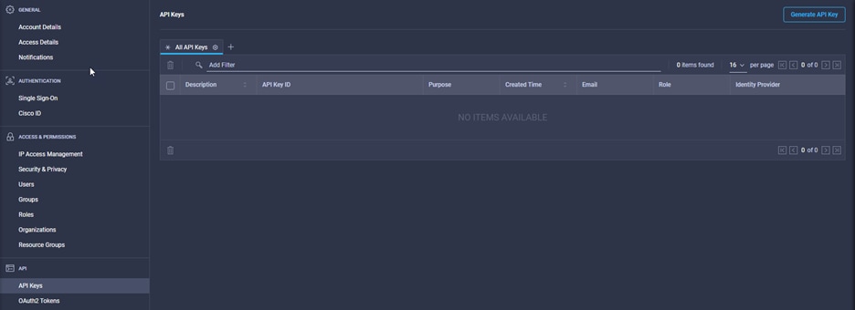
Step 3. Click Generate API Key and enter a description and select Open API schema version 2.
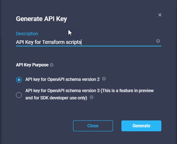
Step 4. Use the icons on the right side of the dialog to copy the Secret Key as a text document and save the file in a location accessible on the Terraform workstation.
IMPORTANT! This is the only one time that the secret key can be viewed or downloaded. You cannot recover them later. However, you can create new access keys at any time.
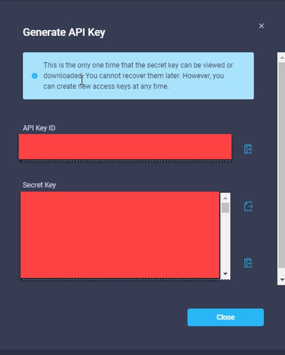
Step 5. Use the icon on the right side of the dialog to copy the API Key ID to the clipboard. Save this file SecretKet.txt to a location the Terraform scripts have access to.
Network Switch Configuration
This section provides a detailed procedure for configuring the Cisco Nexus 93180YC-FX switches for use in a FlexPod environment. The Cisco Nexus 93180YC-FX will be used for LAN switching in this solution.
Note: Follow these steps precisely because failure to do so could result in an improper configuration.
Follow the physical connectivity guidelines for FlexPod as explained in section FlexPod Cabling.
Before the Ansible Nexus switch setup playbook can be run, the Cisco Nexus switches must be brought up with a management IP address. The following procedures describe the basic configuration of the Cisco Nexus switches for use in a base FlexPod environment. This procedure assumes the use of Cisco Nexus 9000 9.3(8), the Cisco suggested Nexus switch release at the time of this validation.
Note: The following procedure includes the setup of NTP distribution on both the mgmt0 port and the in-band management VLAN. The interface-vlan feature and ntp commands are used to set this up. This procedure also assumes that the default VRF is used to route the in-band management VLAN.
Note: In this validation, port speed and duplex are hard set at both ends of every 100GE connection.
Note: This validation assumes that both switches have been reset to factory defaults by using the “write erase” command followed by the “reload” command.
Procedure 1. Set Up Initial Configuration
Cisco Nexus A
Note: Set up the initial configuration for the Cisco Nexus A switch, from a serial console.
Step 1. Configure the switch.
Note: On initial boot and connection to the serial or console port of the switch, the NX-OS setup should automatically start and attempt to enter Power on Auto Provisioning.
Abort Power On Auto Provisioning [yes - continue with normal setup, skip – bypass password and basic configuration, no - continue with Power On Auto Provisioning] (yes/skip/no)[no]: yes
Disabling POAP.......Disabling POAP
poap: Rolling back, please wait... (This may take 5-15 minutes)
---- System Admin Account Setup ----
Do you want to enforce secure password standard (yes/no) [y]: Enter
Enter the password for "admin": <password>
Confirm the password for "admin": <password>
Would you like to enter the basic configuration dialog (yes/no): yes
Create another login account (yes/no) [n]: Enter
Configure read-only SNMP community string (yes/no) [n]: Enter
Configure read-write SNMP community string (yes/no) [n]: Enter
Enter the switch name: <nexus-A-hostname>
Continue with Out-of-band (mgmt0) management configuration? (yes/no) [y]: Enter
Mgmt0 IPv4 address: <nexus-A-mgmt0-ip>
Mgmt0 IPv4 netmask: <nexus-A-mgmt0-netmask>
Configure the default gateway? (yes/no) [y]: Enter
IPv4 address of the default gateway: <nexus-A-mgmt0-gw>
Configure advanced IP options? (yes/no) [n]: Enter
Enable the telnet service? (yes/no) [n]: Enter
Enable the ssh service? (yes/no) [y]: Enter
Type of ssh key you would like to generate (dsa/rsa) [rsa]: Enter
Number of rsa key bits <1024-2048> [1024]: Enter
Configure the ntp server? (yes/no) [n]: Enter
Configure default interface layer (L3/L2) [L2]: Enter
Configure default switchport interface state (shut/noshut) [noshut]: shut
Enter basic FC configurations (yes/no) [n]: n
Configure CoPP system profile (strict/moderate/lenient/dense) [strict]: Enter
Would you like to edit the configuration? (yes/no) [n]: Enter
Step 2. Review the configuration summary before enabling the configuration.
Use this configuration and save it? (yes/no) [y]: Enter
Cisco Nexus B
Note: Set up the initial configuration for the Cisco Nexus B switch, from a serial console.
Step 1. Configure the switch.
Note: On initial boot and connection to the serial or console port of the switch, the NX-OS setup should automatically start and attempt to enter Power on Auto Provisioning.
Abort Power On Auto Provisioning [yes - continue with normal setup, skip - bypass password and basic configuration, no - continue with Power On Auto Provisioning] (yes/skip/no) [no]: yes
Disabling POAP.......Disabling POAP
poap: Rolling back, please wait... (This may take 5-15 minutes)
---- System Admin Account Setup ----
Do you want to enforce secure password standard (yes/no) [y]: Enter
Enter the password for "admin": <password>
Confirm the password for "admin": <password>
Would you like to enter the basic configuration dialog (yes/no): yes
Create another login account (yes/no) [n]: Enter
Configure read-only SNMP community string (yes/no) [n]: Enter
Configure read-write SNMP community string (yes/no) [n]: Enter
Enter the switch name: <nexus-B-hostname>
Continue with Out-of-band (mgmt0) management configuration? (yes/no) [y]: Enter
Mgmt0 IPv4 address: <nexus-B-mgmt0-ip>
Mgmt0 IPv4 netmask: <nexus-B-mgmt0-netmask>
Configure the default gateway? (yes/no) [y]: Enter
IPv4 address of the default gateway: <nexus-B-mgmt0-gw>
Configure advanced IP options? (yes/no) [n]: Enter
Enable the telnet service? (yes/no) [n]: Enter
Enable the ssh service? (yes/no) [y]: Enter
Type of ssh key you would like to generate (dsa/rsa) [rsa]: Enter
Number of rsa key bits <1024-2048> [1024]: Enter
Configure the ntp server? (yes/no) [n]: Enter
Configure default interface layer (L3/L2) [L2]: Enter
Configure default switchport interface state (shut/noshut) [noshut]: shut
Enter basic FC configurations (yes/no) [n]: Enter
Configure CoPP system profile (strict/moderate/lenient/dense) [strict]: Enter
Would you like to edit the configuration? (yes/no) [n]: Enter
2. Review the configuration summary before enabling the configuration.
Use this configuration and save it? (yes/no) [y]: Enter
Procedure 2. Ansible Nexus Switch Configuration
Note: Configure the Cisco Nexus switches from the management workstation.
Step 1. Add Nexus switch ssh keys to /root/.ssh/known_hosts. Adjust known_hosts as necessary if errors occur.
ssh admin@<nexus-A-mgmt0-ip>
exit
ssh admin@<nexus-B-mgmt0-ip>
exit
Step 2. Edit the following variable files to ensure proper Cisco Nexus variables are entered:
● FlexPod-for-EHR/Ansible//inventory
● FlexPod-for-EHR/Ansible/group_vars/all.yml
● FlexPod-for-EHR/Ansible/host_vars/n9kA.yml
● FlexPod-for-EHR/Ansible/host_vars/n9kB.yml
● FlexPod-for-EHR/Ansible/roles/NEXUSconfig/defaults/main.yml
Step 3. From /root/ FlexPod-for-EHR/Ansible/, run the Setup_Nexus.yml Ansible playbook.
ansible-playbook ./Setup_Nexus.yml -i inventory
Step 4. Once the Ansible playbook has been run on both switches, it is important to configure the local time so that logging time alignment and any backup schedules are correct. For more information on configuring the timezone and daylight savings time or summertime, please see Cisco Nexus 9000 Series NX-OS Fundamentals Configuration Guide, Release 9.3(x). Sample clock commands for the United States Eastern timezone are:
clock timezone EST -5 0
clock summer-time EDT 2 Sunday March 02:00 1 Sunday November 02:00 60
Step 5. ssh into each switch and execute the following commands:
clock timezone <timezone> <hour-offset> <minute-offset>
clock summer-time <timezone> <start-week> <start-day> <start-month> <start-time> <end-week> <end-day> <end-month> <end-time> <offset-minutes>
Procedure 3. FlexPod Cisco Nexus Switch Manual Configuration
Note: Enable features on Cisco Nexus A and Cisco Nexus B.
Step 1. Log in as admin using ssh.
Step 2. Run the following commands:
config t
feature nxapi
feature udld
feature interface-vlan
feature lacp
feature vpc
feature lldp
Procedure 4. Set Global Configurations
Cisco Nexus A and Cisco Nexus B
Step 1. Run the following commands to set global configurations:
spanning-tree port type network default
spanning-tree port type edge bpduguard default
spanning-tree port type edge bpdufilter default
port-channel load-balance src-dst l4port
ntp server <global-ntp-server-ip> use-vrf management
ntp master 3
clock timezone <timezone> <hour-offset> <minute-offset>
(For Example: clock timezone EST -5 0)
clock summer-time <timezone> <start-week> <start-day> <start-month> <start-time> <end-week> <end-day> <end-month> <end-time> <offset-minutes>
ip route 0.0.0.0/0 <ib-mgmt-vlan-gateway>
copy run start
Note: It is important to configure the local time so that logging time alignment and any backup schedules are correct. For more information on configuring the timezone and daylight savings time or summer time, please see Cisco Nexus 9000 Series NX-OS Fundamentals Configuration Guide, Release 9.3(x). Sample clock commands for the United States Eastern timezone are:
clock timezone EST -5 0
clock summer-time EDT 2 Sunday March 02:00 1 Sunday November 02:00 60
Cisco Nexus A and Cisco Nexus B
Note: Create the necessary virtual local area networks (VLANs) on both switches.
Step 1. From the global configuration mode, run the following commands:
vlan <oob-mgmt-vlan-id>
name OOB-MGMT
vlan <ib-mgmt-vlan-id>
name IB-MGMT
vlan <native-vlan-id>
name Native-Vlan
vlan <vmotion-vlan-id>
name vMotion
vlan <vm-traffic-vlan-id>
name VM-Traffic
vlan <infra-nfs-vlan-id>
name Infra-NFS
vlan <CIFS-vlan-id>
name CIFS
exit
Procedure 6. Add NTP Distribution Interface
Step 1. From the global configuration mode, run the following commands:
interface vlan <ib-mgmt-vlan-id>
ip address <switch-a-ntp-ip>/<ib-mgmt-vlan-netmask-length>
no shutdown
exit
ntp peer <nexus-B-mgmt0-ip> use-vrf management
Step 1. From the global configuration mode, run the following commands:
interface vlan <ib-mgmt-vlan-id>
ip address <switch-b-ntp-ip>/<ib-mgmt-vlan-netmask-length>
no shutdown
exit
ntp peer <nexus-A-mgmt0-ip> use-vrf management
Procedure 7. Add Individual Port Descriptions for Troubleshooting and Enable UDLD for Cisco UCS Interfaces
Note: In this step and in the following sections, configure the AFF nodename <st-node> and Cisco UCS 6454 fabric interconnect clustername <ucs-clustername> interfaces as appropriate to your deployment.
Step 1. From the global configuration mode, run the following commands:
interface Eth1/25
description <ucs-clustername>-A:1/45
udld enable
interface Eth1/26
description <ucs-clustername>-A:1/46
udld enable
interface Eth1/27
description <ucs-clustername>-B:1/45
udld enable
interface Eth1/28
description <ucs-clustername>-B:1/46
udld enable
Note: For fibre optic connections to Cisco UCS systems (AOC or SFP-based), entering udld enable will result in a message stating that this command is not applicable to fiber ports. This message is expected. If you have fibre optic connections, do not enter the udld enable command.
interface Eth1/17
description <st-clustername>-01:e0e
interface Eth1/18
description <st-clustername>-01:e0f
interface Eth1/19
description <st-clustername>-02:e0e
interface Eth1/20
description <st-clustername>-02:e0f
interface Eth1/49
description <nexus-b-hostname>:1/49
interface Eth1/50
description <nexus-b-hostname>:1/50
interface Eth1/50
description Uplink-SW
exit
Note: Add the individual port descriptions for troubleshooting activity and verification for switch B and to enable aggressive UDLD on copper interfaces connected to Cisco UCS systems.
Step 1. From the global configuration mode, run the following commands:
interface Eth1/25
description <ucs-clustername>-A:1/47
udld enable
interface Eth1/26
description <ucs-clustername>-A:1/48
udld enable
interface Eth1/27
description <ucs-clustername>-B:1/47
udld enable
interface Eth1/28
description <ucs-clustername>-B:1/48
udld enable
Note: For fibre optic connections to Cisco UCS systems (AOC or SFP-based), entering udld enable will result in a message stating that this command is not applicable to fiber ports. This message is expected.
interface Eth1/17
description <st-clustername>-01:e0g
interface Eth1/18
description <st-clustername>-01:e0h
interface Eth1/19
description <st-clustername>-02:e0g
interface Eth1/20
description <st-clustername>-02:e0h
interface Eth1/49
description <nexus-a-hostname>:1/49
interface Eth1/50
description <nexus-a-hostname>:1/50
interface Eth1/50
description Uplink-SW
exit
Procedure 8. Create Port Channels
Cisco Nexus A and Cisco Nexus B
Note: Create the necessary port channels between devices on both switches.
Step 1. From the global configuration mode, run the following commands:
interface Po10
description vPC peer-link
interface Eth1/49-50
channel-group 10 mode active
no shutdown
interface Po17
description <st-clustername>-01
interface Eth1/17-18
channel-group 17 mode active
no shutdown
interface Po19
description <st-clustername>-02
interface Eth1/19-20
channel-group 19 mode active
no shutdown
interface Po25
description <ucs-clustername>-a
interface Eth1/25-26
channel-group 25 mode active
no shutdown
interface Po26
description <ucs-clustername>-b
interface Eth1/27-28
channel-group 123 mode active
no shutdown
interface Po154
description MGMT-Uplink
interface Eth1/54
channel-group 154 mode active
no shutdown
exit
copy run start
Procedure 9. Configure Port Channel Parameters
Cisco Nexus A and Cisco Nexus B
Note: Configure port channel parameters on both switches.
Step 1. From the global configuration mode, run the following commands:
interface Po10
switchport mode trunk
switchport trunk native vlan <native-vlan-id>
switchport trunk allowed vlan <oob-mgmt-vlan-id>, <ib-mgmt-vlan-id>, <infra-nfs-vlan-id>, <vmotion-vlan-id>, <vm-traffic-vlan-id>, <CIFS-vlan-id>
spanning-tree port type network
speed 100000
duplex full
interface Po17
switchport mode trunk
switchport trunk native vlan <native-vlan-id>
switchport trunk allowed vlan <ib-mgmt-vlan-id>, <infra-nfs-vlan-id>,<CIFS-vlan-id>
spanning-tree port type edge trunk
mtu 9216
interface Po19
switchport mode trunk
switchport trunk native vlan <native-vlan-id>
switchport trunk allowed vlan <ib-mgmt-vlan-id>, <infra-nfs-vlan-id>, <CIFS-vlan-id>
spanning-tree port type edge trunk
mtu 9216
interface Po25
switchport mode trunk
switchport trunk native vlan <native-vlan-id>
switchport trunk allowed vlan <oob-mgmt-vlan-id>, <ib-mgmt-vlan-id>, <infra-nfs-vlan-id>, <vmotion-vlan-id>, <vm-traffic-vlan-id>,<CIFS-vlan-id>
spanning-tree port type edge trunk
mtu 9216
interface Po26
switchport mode trunk
switchport trunk native vlan <native-vlan-id>
switchport trunk allowed vlan <oob-mgmt-vlan-id>, <ib-mgmt-vlan-id>, <infra-nfs-vlan-id>, <vmotion-vlan-id>, <vm-traffic-vlan-id>, <CIFS-vlan-id>
spanning-tree port type edge trunk
mtu 9216
interface Po154
switchport mode trunk
switchport trunk native vlan <native-vlan-id>
switchport trunk allowed vlan <oob-mgmt-vlan-id>, <ib-mgmt-vlan-id>
spanning-tree port type network
mtu 9216
exit
copy run start
Procedure 10. Configure Virtual Port Channels
Step 1. From the global configuration mode, run the following commands:
vpc domain <nexus-vpc-domain-id>
role priority 10
peer-keepalive destination <nexus-B-mgmt0-ip> source <nexus-A-mgmt0-ip>
peer-switch
peer-gateway
auto-recovery
delay restore 150
ip arp synchronize
interface Po10
vpc peer-link
interface Po17
vpc 17
interface Po19
vpc 19
interface Po25
vpc 21
interface Po26
vpc 26
interface Po154
vpc 154
exit
copy run start
Step 1. From the global configuration mode, run the following commands:
vpc domain <nexus-vpc-domain-id>
role priority 20
peer-keepalive destination <nexus-A-mgmt0-ip> source <nexus-B-mgmt0-ip>
peer-switch
peer-gateway
auto-recovery
delay restore 150
ip arp synchronize
interface Po10
vpc peer-link
interface Po7
vpc 17
interface Po19
vpc 19
interface Po25
vpc 25
interface Po26
vpc 26
interface Po154
vpc 154
exit
copy run start
Procedure 11. Switch Testing Commands
Note: These commands can be used to check for correct switch configuration. Some of these commands need to be run after further configuration of the FlexPod components are completed to see complete results.
show run
show vpc
show port-channel summary
show ntp peer-status
show cdp neighbors
show lldp neighbors
show run int
show int
show udld neighbors
show int status
Storage Configuration
See section NetApp Hardware Universe for planning the physical location of the storage systems:
● Site Preparation
● System Connectivity Requirements
● Circuit Breaker, Power Outlet Balancing, System Cabinet Power Cord Plugs, and Console Pinout Requirements
● AFF Series Systems
The NetApp Hardware Universe (HWU) application provides supported hardware and software components for any specific ONTAP version. It also provides configuration information for all the NetApp storage appliances currently supported by ONTAP software and a table of component compatibilities.
To confirm that the hardware and software components that you would like to use are supported with the version of ONTAP that you plan to install, follow these steps at the NetApp Support site.
1. Access the HWU application to view the System Configuration guides. Click the Platforms menu to view the compatibility between different version of the ONTAP software and the NetApp storage appliances with your desired specifications.
2. Alternatively, to compare components by storage appliance, click Compare Storage Systems.
Follow the physical installation procedures for the controllers found here: https://docs.netapp.com/us-en/ontap-systems/index.html.
NetApp storage systems support a wide variety of disk shelves and disk drives. The complete list of disk shelves that are supported by the AFF A400 and AFF A800 is available at the NetApp Support site.
When using SAS disk shelves with NetApp storage controllers, refer to: https://docs.netapp.com/us-en/ontap-systems/sas3/index.html for proper cabling guidelines.
When using NVMe drive shelves with NetApp storage controllers, refer to: https://docs.netapp.com/us-en/ontap-systems/ns224/index.html for installation and servicing guidelines.
Complete Configuration Worksheet
Note: Before running the setup script, complete the Cluster setup worksheet in the ONTAP 9 Documentation Center. You must have access to the NetApp Support site to open the cluster setup worksheet.
Procedure 1. Ansible Storage Configuration
End-to-End ONTAP Storage Configuration for a FlexPod is automated with Ansible. ONTAP Storage can be deployed via Ansible after the ONTAP Cluster setup is complete and the Cluster management network is configured.
A playbook by name ‘Setup_ONTAP.yml’ is available at the root of this repository. It calls all the required roles to complete the setup of the ONTAP storage system.
The ONTAP setup is split into three sections, use the tags - ontap_config_part_1, ontap_config_part_2 and ontap_config_part_3 to execute parts of the playbook at the appropriate stage of setup.
Step 1. Execute the playbook from the Ansible Control machine as an admin/ root user using the following commands:
Step 2. After setup of Cisco Nexus switches:
ansible-playbook -i inventory Setup_ONTAP.yml -t ontap_config_part_1
Step 3. After setup of Cisco UCS:
ansible-playbook -i inventory Setup_ONTAP.yml -t ontap_config_part_2
Step 4. After setup of VMware vSphere 7.0 Setup:
ansible-playbook -i inventory Setup_ONTAP.yml -t ontap_config_part_3
Step 5. Optional: If you would like to run a part of the deployment, you may use the appropriate tag that accompanies each task in the role and run the playbook by executing the following command:
ansible-playbook -i inventory Setup_ONTAP.yml -t <tag_name>
Configure ONTAP Nodes
Before running the setup script, review the configuration worksheets in the Software setup section of the ONTAP 9 Documentation Center to learn about configuring ONTAP. Table 9 lists the information needed to configure two ONTAP nodes. Customize the cluster detail values with the information applicable to your deployment.
Table 9. ONTAP Software Installation Prerequisites
| Cluster Detail |
Cluster Detail Value |
| Cluster node 01 IP address |
<node01-mgmt-ip> |
| Cluster node 01 netmask |
<node01-mgmt-mask> |
| Cluster node 01 gateway |
<node01-mgmt-gateway> |
| Cluster node 02 IP address |
<node02-mgmt-ip> |
| Cluster node 02 netmask |
<node02-mgmt-mask> |
| Cluster node 02 gateway |
<node02-mgmt-gateway> |
| ONTAP 9.10 URL (http server hosting ONTAP software) |
<url-boot-software> |
Procedure 1. Configure Node 01
Step 1. Connect to the storage system console port. You should see a Loader-A prompt. However, if the storage system is in a reboot loop, press Ctrl-C to exit the autoboot loop when the following message displays:
Starting AUTOBOOT press Ctrl-C to abort...
Step 2. Allow the system to boot up.
autoboot
Step 3. Press Ctrl-C when prompted.
Note: If ONTAP 9.10.1P1 is not the version of software being booted, continue with the following steps to install new software. If ONTAP 9.10.1P1 is the version being booted, select option 8 and y to reboot the node. Then continue with section Set Up Node.
Step 4. To install new software, select option 7 from the menu.
Step 5. Enter y to continue the installation.
Step 6. Select e0M for the network port for the download.
Step 7. Enter n to skip the reboot.
Step 8. Select option 7 from the menu: Install new software first
Step 9. Enter y to continue the installation
Step 10. Enter the IP address, netmask, and default gateway for e0M.
Enter the IP address for port e0M: <node01-mgmt-ip>
Enter the netmask for port e0M: <node01-mgmt-mask>
Enter the IP address of the default gateway: <node01-mgmt-gateway>
Step 11. Enter the URL where the software can be found.
Note: The e0M interface should be connected to management network and the web server must be reachable (using ping) from node 01.
<url-boot-software>
Step 12. Press Enter for the user name, indicating no user name.
Step 13. Enter y to set the newly installed software as the default to be used for subsequent reboots.
Step 14. Enter yes to reboot the node.
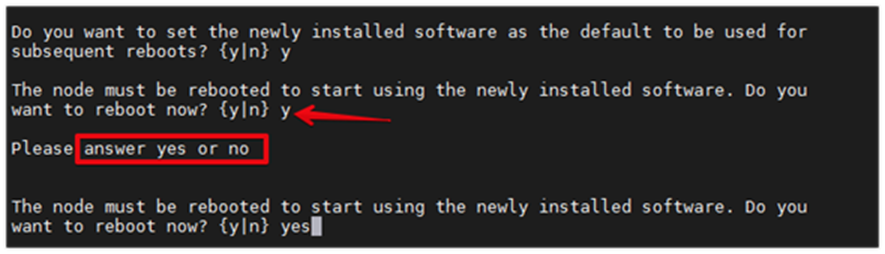
Note: When installing new software, the system might perform firmware upgrades to the BIOS and adapter cards, causing reboots and possible stops at the Loader-A prompt. If these actions occur, the system might deviate from this procedure.
Note: During the ONTAP installation a prompt to reboot the node requests a Y/N response. The prompt requires the entire Yes or No response to reboot the node and continue the installation.
Step 15. Press Ctrl-C when the following message displays:
Press Ctrl-C for Boot Menu
Step 16. Select option 4 for Clean Configuration and Initialize All Disks.
Step 17. Enter y to zero disks, reset config, and install a new file system.
Step 18. Enter yes to erase all the data on the disks.
Note: The initialization and creation of the root aggregate can take 90 minutes or more to complete, depending on the number and type of disks attached. When initialization is complete, the storage system reboots. Note that SSDs take considerably less time to initialize. You can continue with the configuration of node 02 while the disks for node 01 are zeroing.
Procedure 2. Configure Node 02
Step 1. Connect to the storage system console port. You should see a Loader-B prompt. However, if the storage system is in a reboot loop, press Ctrl-C to exit the autoboot loop when the following message displays:
Starting AUTOBOOT press Ctrl-C to abort...
Step 2. Allow the system to boot up.
autoboot
Step 3. Press Ctrl-C when prompted.
Note: If ONTAP 9.10.1P1 is not the version of software being booted, continue with the following steps to install new software. If ONTAP 9.10.1P1 is the version being booted, select option 8 and y to reboot the node, then continue with section Set Up Node.
Step 4. To install new software, select option 7.
Step 5. Enter y to continue the installation.
Step 6. Select e0M for the network port you want to use for the download.
Step 7. Enter n to skip the reboot.
Step 8. Select option 7: Install new software first
Step 9. Enter y to continue the installation.
Step 10. Enter the IP address, netmask, and default gateway for e0M.
Enter the IP address for port e0M: <node02-mgmt-ip>
Enter the netmask for port e0M: <node02-mgmt-mask>
Enter the IP address of the default gateway: <node02-mgmt-gateway>
Step 11. Enter the URL where the software can be found.
Note: The web server must be reachable (ping) from node 02.
<url-boot-software>
Step 12. Press Enter for the username, indicating no user name.
Step 13. Enter y to set the newly installed software as the default to be used for subsequent reboots.
Step 14. Enter yes to reboot the node.

Note: When installing new software, the system might perform firmware upgrades to the BIOS and adapter cards, causing reboots and possible stops at the Loader-A prompt. If these actions occur, the system might deviate from this procedure.
Note: During the ONTAP installation a prompt to reboot the node requests a Y/N response. The prompt requires the entire Yes or No response to reboot the node and continue the installation.
Step 15. Press Ctrl-C when you see this message:
Press Ctrl-C for Boot Menu
Step 16. Select option 4 for Clean Configuration and Initialize All Disks.
Step 17. Enter y to zero disks, reset config, and install a new file system.
Step 18. Enter yes to erase all the data on the disks.
Note: The initialization and creation of the root aggregate can take 90 minutes or more to complete, depending on the number and type of disks attached. When initialization is complete, the storage system reboots. Note that SSDs take considerably less time to initialize.
Procedure 3. Set Up Node
Note: From a console port program attached to the storage controller A (node 01) console port, run the node setup script. This script appears when ONTAP 9.10.1P1 boots on the node for the first time.
Step 1. Follow the prompts to set up node 01.
Welcome to node setup.
You can enter the following commands at any time:
"help" or "?" - if you want to have a question clarified,
"back" - if you want to change previously answered questions, and
"exit" or "quit" - if you want to quit the setup wizard.
Any changes you made before quitting will be saved.
You can return to cluster setup at any time by typing "cluster setup".
To accept a default or omit a question, do not enter a value.
This system will send event messages and weekly reports to NetApp Technical
Support.
To disable this feature, enter "autosupport modify -support disable" within 24
hours.
Enabling AutoSupport can significantly speed problem determination and resolution
should a problem occur on your system.
For further information on AutoSupport, see:
http://support.netapp.com/autosupport/
Type yes to confirm and continue {yes}: yes
Enter the node management interface port [e0M]: Enter
Enter the node management interface IP address: <node01-mgmt-ip>
Enter the node management interface netmask: <node01-mgmt-mask>
Enter the node management interface default gateway: <node01-mgmt-gateway>
A node management interface on port e0M with IP address <node01-mgmt-ip> has been
created
Use your web browser to complete cluster setup by accessing https://<node01-mgmt-
ip>
Otherwise press Enter to complete cluster setup using the command line interface:
Step 2. To complete cluster setup, open a web browser and navigate to https://node01-mgmt-ip.
Table 10. Cluster Create in ONTAP Prerequisites
| Cluster Detail |
Cluster Detail Value |
| Cluster name |
<clustername> |
| Cluster Admin SVM |
<cluster-adm-svm> |
| Infrastructure Data SVM |
<infra-data-svm> |
| ONTAP base license |
<cluster-base-license-key> |
| Cluster management IP address |
<clustermgmt-ip> |
| Cluster management netmask |
<clustermgmt-mask> |
| Cluster management gateway |
<clustermgmt-gateway> |
| Cluster node 01 IP address |
<node01-mgmt-ip> |
| Cluster node 01 netmask |
<node01-mgmt-mask> |
| Cluster node 01 gateway |
<node01-mgmt-gateway> |
| Cluster node 02 IP address |
<node02-mgmt-ip> |
| Cluster node 02 netmask |
<node02-mgmt-mask> |
| Cluster node 02 gateway |
<node02-mgmt-gateway> |
| Node 01 service processor IP address |
<node01-sp-ip> |
| Node 01 service processor network mask |
<node01-sp-mask> |
| Node 01 service processor gateway |
<node01-sp-gateway> |
| Node 02 service processor IP address |
<node02-sp-ip> |
| Node 02 service processor network mask |
<node02-sp-mask> |
| Node 02 service processor gateway |
<node02-sp-gateway> |
| Node 01 node name |
<st-node01> |
| Node 02 node name |
<st-node02> |
| DNS domain name |
<dns-domain-name> |
| DNS server IP address |
<dns-ip> |
| NTP server A IP address |
<switch-a-ntp-ip> |
| NTP server B IP address |
<switch-b-ntp-ip> |
| SNMPv3 User |
<snmp-v3-usr> |
| SNMPv3 Authentication Protocol |
<snmp-v3-auth-proto> |
| SNMPv3 Privacy Protocol |
<snmpv3-priv-proto> |
Note: Cluster setup can also be performed using the CLI. This document describes the cluster setup using the NetApp ONTAP System Manager guided setup.
Step 3. Complete the required information on the Initialize Storage System screen:
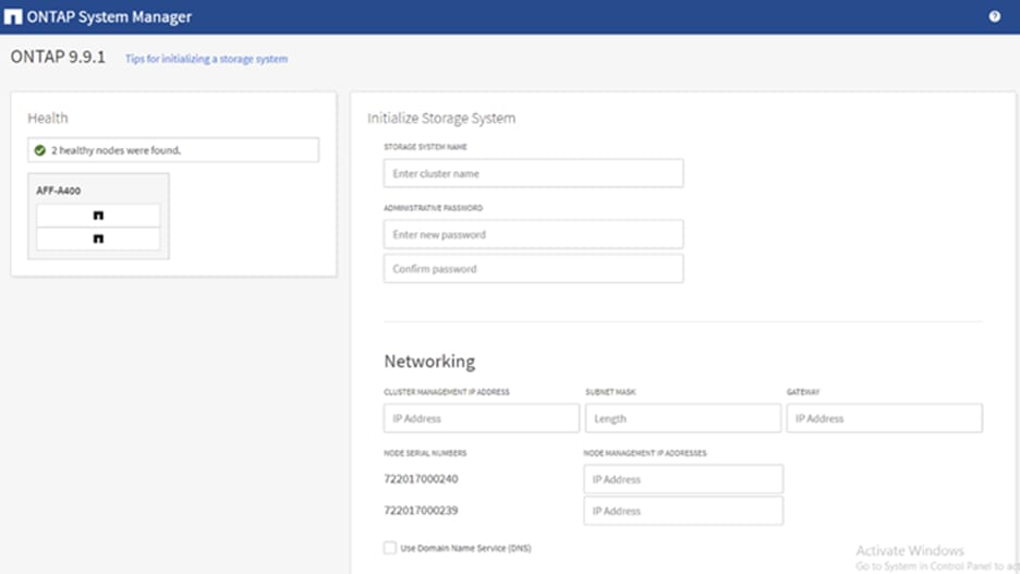
Step 4. In the Cluster screen, follow these steps:
a. Enter the cluster name and administrator password.
b. Complete the Networking information for the cluster and each node.
c. Check the box for Use time services (NTP) and enter the IP addresses of the time servers in a comma separated list.
Note: The nodes should be discovered automatically; if they are not, Refresh the browser page. By default, the cluster interfaces are created on all the new factory shipping storage controllers.
Note: If all the nodes are not discovered, then configure the cluster using the command line.
Note: The node management interface can be on the same subnet as the cluster management interface, or it can be on a different subnet. In this document, we assume that it is on the same subnet.
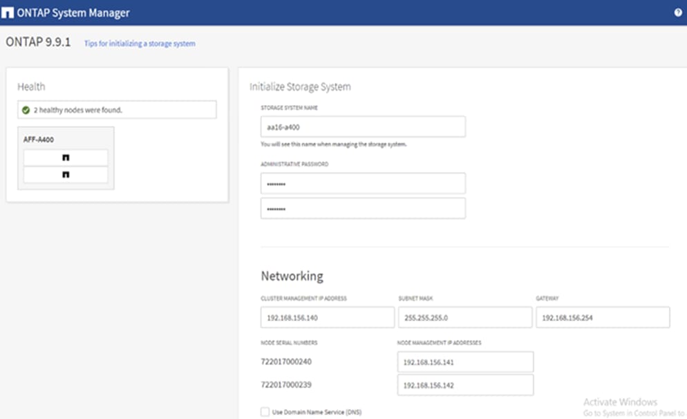
Step 5. Click Submit.
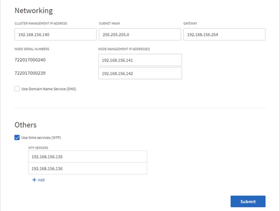
Step 6. A few minutes will pass while the cluster is configured. When prompted, login to ONTAP System Manager to continue the cluster configuration.
Note: You can use Ansible scripts at this point to configure the remaining part of the Storage Configurations.
Step 7. Edit the following variable files to ensure proper ONTAP Storage variables are entered:
● FlexPod-for-EHR/Ansible/inventory
● FlexPod-for-EHR/Ansible/group_vars/all.yml
● FlexPod-for-EHR/Ansible/group_vars/ontap
● FlexPod-for-EHR/Ansible/vars/ontap_main.yml
Step 8. From /root/ FlexPod-for-EHR/Ansible, run the Setup_ONTAP.yml Ansible playbook.
ansible-playbook -i inventory Setup_ONTAP.yml -t ontap_config_part_1
Note: Use the -vvv tag to see detailed execution output log.
Note: Ansible will implement all the Storage configurations tasks in this section. Skip the below steps and move to the Cisco UCS Configuration section.
Step 9. From the Dashboard click the Cluster menu on the left and select Overview.
Step 10. Click the More ellipsis button in the Overview pane at the top right of the screen and select Edit.
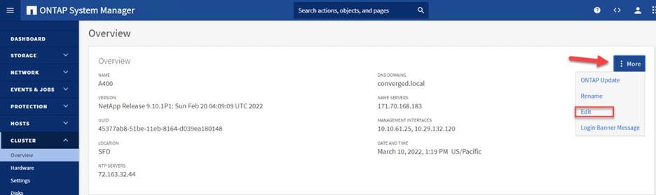
Step 11. Add additional cluster configuration details and click Save to make the changes persistent:
a. Cluster location
b. DNS domain name
c. DNS server IP addresses
Note: DNS server IP addresses can be added individually or with a comma separated list on a single line.
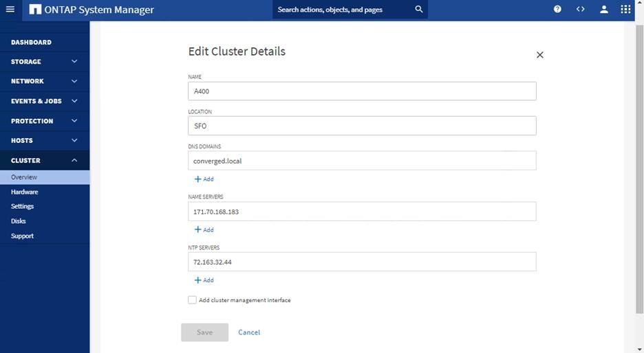
Step 12. Click Save to make the changes persistent.
Step 13. Select the Settings menu under the Cluster menu.
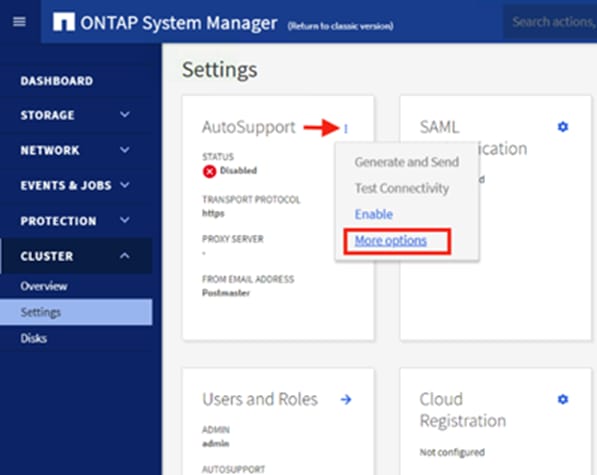
Step 14. If AutoSupport was not configured during the initial setup, click the ellipsis in the AutoSupport tile and select More options.
Step 15. To enable AutoSupport click the slider.
Step 16. Click Edit to change the transport protocol, add a proxy server address and a mail host as needed.
Step 17. Click Save to enable the changes.
Step 18. In the Email tile to the right, click Edit and enter the desired email information:
a. Email send from address
b. Email recipient addresses
c. Recipient Category
Step 19. Click Save when complete.
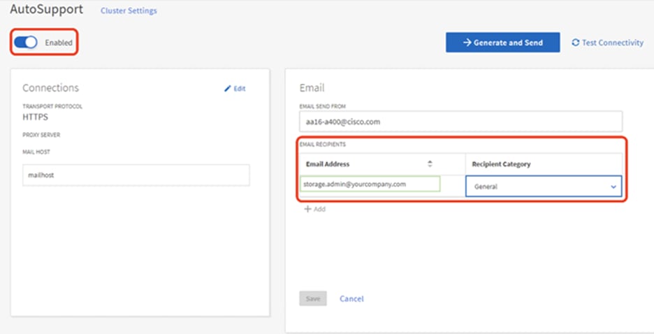
Step 20. Select CLUSTER > Settings at the top left of the page to return to the cluster settings page.
Step 21. Locate the Licenses tile on the right and click the detail arrow.
Step 22. Add the desired licenses to the cluster by clicking Add and entering the license keys in a comma separated list.
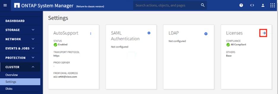
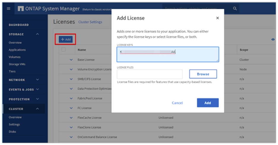
Step 23. Configure storage aggregates by selecting the Storage menu on the left and selecting Tiers.
Step 24. Click Add Local Tier and allow ONTAP System Manager to recommend a storage aggregate configuration.
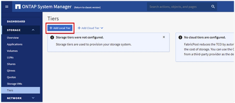
Step 25. ONTAP will use best practices to recommend an aggregate layout. Click the Recommended details link to view the aggregate information.
Step 26. Optionally, enable NetApp Aggregate Encryption (NAE) by checking the box for Configure Onboard Key Manager for encryption.
Step 27. Enter and confirm the passphrase and save it in a secure location for future use.
Step 28. Click Save to make the configuration persistent.
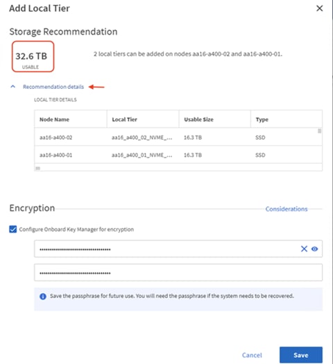
Note: Careful consideration should be taken before enabling aggregate encryption. Aggregate encryption may not be supported for all deployments. Please review the NetApp Encryption Power Guide and the Security Hardening Guide for NetApp ONTAP 9 (TR-4569) to help determine if aggregate encryption is right for your environment.
Procedure 4. Log into the Cluster
Step 1. Open an SSH connection to either the cluster IP or the host name.
Step 2. Log into the admin user with the password you provided earlier.
Procedure 5. Verify Storage Failover
Step 1. Verify the status of the storage failover.
storage failover show
Note: Both <st-node01> and <st-node02> must be capable of performing a takeover. Continue with step 2 if the nodes can perform a takeover.
Step 2. Enable failover on one of the two nodes if it was not completed during the installation.
storage failover modify -node <st-node01> -enabled true
Note: Enabling failover on one node enables it for both nodes.
Step 3. Verify the HA status for a two-node cluster.
Note: This step is not applicable for clusters with more than two nodes.
cluster ha show
Step 4. If HA is not configured use the below commands. Only enable HA mode for two-node clusters. Do not run this command for clusters with more than two nodes because it causes problems with failover.
cluster ha modify -configured true
Do you want to continue? {y|n}: y
Step 5. Verify that hardware assist is correctly configured.
storage failover hwassist show
Step 6. If hwassist storage failover is not enabled, enable using the following commands.
storage failover modify --hwassist-partner-ip <node02-mgmt-ip> -node <st-node01>
storage failover modify --hwassist-partner-ip <node01-mgmt-ip> -node <st-node02>
Procedure 6. Set Auto-Revert on Cluster Management
Note: A storage virtual machine (SVM) is referred to as a Vserver or vserver in the GUI and CLI.
Step 1. Run the following command:
net interface modify -vserver <clustername> -lif cluster_mgmt_lif_1 -auto-revert true
Procedure 7. Zero All Spare Disks
Step 2. To zero all spare disks in the cluster, run the following command:
disk zerospares
Note: Advanced Data Partitioning creates a root partition and two data partitions on each SSD drive in an AFF configuration. Disk autoassign should have assigned one data partition to each node in an HA pair. If a different disk assignment is required, disk autoassignment must be disabled on both nodes in the HA pair by running the disk option modify command. Spare partitions can then be moved from one node to another by running the disk removeowner and disk assign commands.
Procedure 8. Set Up Service Processor Network Interface
Step 1. To assign a static IPv4 address to the Service Processor on each node, run the following commands:
system service-processor network modify -node <st-node01> -address-family IPv4 -enable true -dhcp none -ip-address <node01-sp-ip> -netmask <node01-sp-mask> -gateway <node01-sp-gateway>
system service-processor network modify -node <st-node02> -address-family IPv4 -enable true -dhcp none -ip-address <node02-sp-ip> -netmask <node02-sp-mask> -gateway <node02-sp-gateway>
Note: The Service Processor IP addresses should be in the same subnet as the node management IP addresses.
Procedure 9. Create Manual Provisioned Aggregates (Optional)
Note: An aggregate containing the root volume is created during the ONTAP setup process. To manually create additional aggregates, determine the aggregate name, the node on which to create it, and the number of disks it should contain.
Step 1. To create new aggregates, run the following commands:
storage aggregate create -aggregate <aggr1_node01> -node <st-node01> -diskcount <num-disks> -disktype SSD-NVM
storage aggregate create -aggregate <aggr1_node02> -node <st-node02> -diskcount <num-disks> -disktype SSD-NVM
Note: Customers should have the minimum number of hot spare disks for the recommended hot spare disk partitions for their aggregate.
Note: For all-flash aggregates, you should have a minimum of one hot spare disk or disk partition. For non-flash homogenous aggregates, you should have a minimum of two hot spare disks or disk partitions. For Flash Pool aggregates, you should have a minimum of two hot spare disks or disk partitions for each disk type.
Note: In an AFF configuration with a small number of SSDs, you might want to create an aggregate with all, but one remaining disk (spare) assigned to the controller.
Note: The aggregate cannot be created until disk zeroing completes. Run the storage aggregate show command to display the aggregate creation status. Do not proceed until both aggr1_node01 and aggr1_node02 are online.
Procedure 10. Remove Default Broadcast Domains
Note: By default, all network ports are included in separate default broadcast domain. Network ports used for data services (for example, e0e, e0f, and so on) should be removed from their default broadcast domain and that broadcast domain should be deleted.
Step 1. To perform this task, run the following commands:
network port broadcast-domain delete -broadcast-domain <Default-N> -ipspace Default
network port broadcast-domain show
Note: Delete the Default broadcast domains with Network ports (Default-1, Default-2, and so on).
Procedure 11. Disable Flow Control on 25/100GbE Data Ports
Step 1. Run the following command to configure the ports on node 01:
network port modify -node <st-node01> -port e4a,e4b -flowcontrol-admin none
network port modify -node <st-node01> -port e0e,e0f,e0g,e0h -flowcontrol-admin none
Step 2. Run the following command to configure the ports on node 02:
network port modify -node <st-node02> -port e4a,e4b -flowcontrol-admin none
network port modify -node <st-node02> -port e0e,e0f,e0g,e0h -flowcontrol-admin none
aa16-a400::> net port show -node * -port e0e,e0f,e0g,e0h -fields speed- admin,duplex-admin,flowcontrol-admin
(network port show)
node port duplex-admin speed-admin flowcontrol-admin
------------ ---- ------------ ----------- -----------------
aa16-a400-01 e0e auto auto none
aa16-a400-01 e0f auto auto none
aa16-a400-01 e0g auto auto none
aa16-a400-01 e0h auto auto none
aa16-a400-02 e0e auto auto none
aa16-a400-02 e0f auto auto none
aa16-a400-02 e0g auto auto none
aa16-a400-02 e0h auto auto none
8 entries were displayed.
aa16-a400::> net port show -node * -port e4a,e4b -fields speed-admin,duplex- admin,flowcontrol-admin
(network port show)
node port duplex-admin speed-admin flowcontrol-admin
------------ ---- ------------ ----------- -----------------
aa16-a400-01 e4a auto auto none
aa16-a400-01 e4b auto auto none
aa16-a400-02 e4a auto auto none
aa16-a400-02 e4b auto auto none
4 entries were displayed.
Procedure 12. Disable Auto-Negotiate on Fibre Channel Ports
Step 1. Disable each FC adapter in the controllers with the fcp adapter modify command.
fcp adapter modify -node <st-node01> -adapter 5a --status-admin down
fcp adapter modify -node <st-node01> -adapter 5b --status-admin down
fcp adapter modify -node <st-node02> -adapter 5a --status-admin down
fcp adapter modify -node <st-node02> -adapter 5b --status-admin down
Step 2. Set the desired speed on the adapter and return it to the online state.
fcp adapter modify -node <st-node01> -adapter 5a -speed 32 -status-admin up
fcp adapter modify -node <st-node01> -adapter 5b -speed 32 -status-admin up
fcp adapter modify -node <st-node02> -adapter 5a -speed 32 -status-admin up
fcp adapter modify -node <st-node02> -adapter 5b -speed 32 -status-admin up
Procedure 13. Enable Cisco Discovery Protocol
Step 1. To enable the Cisco Discovery Protocol (CDP) on the NetApp storage controllers, run the following command to enable CDP in ONTAP:
node run -node * options cdpd.enable on
Note: To be effective, CDP must also be enabled on directly connected networking equipment such as switches and routers.
Procedure 14. Enable Link-layer Discovery Protocol on all Ethernet Ports
Note: You need to enable the exchange of Link-layer Discovery Protocol (LLDP) neighbor information between the storage and network switches.
Step 1. Enable LLDP on all ports of all nodes in the cluster.
node run * options lldp.enable on
Procedure 15. Create Management Broadcast Domain
Step 1. If the management interfaces are required to be on a separate VLAN, create a new broadcast domain for those interfaces by running the following command:
network port broadcast-domain create -broadcast-domain IB-MGMT -mtu 1500
network port broadcast-domain show
Procedure 16. Create NFS Broadcast Domain
Step 1. To create an NFS data broadcast domain with a maximum transmission unit (MTU) of 9000, run the following commands to create a broadcast domain for NFS in ONTAP:
network port broadcast-domain create -broadcast-domain Infra_NFS -mtu 9000
network port broadcast-domain show
Procedure 17. Create CIFS Broadcast Domain
Step 1. To create an CIFs data broadcast domain with a maximum transmission unit (MTU) of 9000, run the following commands to create a broadcast domain for NFS in ONTAP:
network port broadcast-domain create -broadcast-domain Infra_CIFS -mtu 9000
network port broadcast-domain show
Procedure 18. Create Interface Groups
Step 1. To create the LACP interface groups for the 25GbE data interfaces, run the following commands:
network port ifgrp create -node <st-node01> -ifgrp a0a -distr-func port -mode multimode_lacp
network port ifgrp add-port -node <st-node01> -ifgrp a0a -port e0e
network port ifgrp add-port -node <st-node01> -ifgrp a0a -port e0f
network port ifgrp add-port -node <st-node01> -ifgrp a0a -port e0g
network port ifgrp add-port -node <st-node01> -ifgrp a0a -port e0h
network port ifgrp create -node <st-node02> -ifgrp a0a -distr-func port -mode multimode_lacp
network port ifgrp add-port -node <st-node02> -ifgrp a0a -port e0e
network port ifgrp add-port -node <st-node02> -ifgrp a0a -port e0f
network port ifgrp add-port -node <st-node02> -ifgrp a0a -port e0g
network port ifgrp add-port -node <st-node02> -ifgrp a0a -port e0h
network port ifgrp show
Procedure 19. Change MTU on Interface Groups
Step 1. To change the MTU size on the base interface-group ports before creating the VLAN ports, run the following commands:
network port modify -node <st-node01> -port a0a -mtu 9000
network port modify -node <st-node02> -port a0a -mtu 9000
Step 1. Create the management VLAN ports and add them to the management broadcast domain.
network port vlan create -node <st-node01> -vlan-name a0a-<ib-mgmt-vlan-id>
network port vlan create -node <st-node02> -vlan-name a0a-<ib-mgmt-vlan-id>
network port broadcast-domain add-ports -broadcast-domain IB-MGMT -ports <st-node01>:a0a-<ib-mgmt-vlan-id>,<st-node02>:a0a-<ib-mgmt-vlan-id>
network port vlan show
Step 2. Create the NFS VLAN ports and add them to the Infra_NFS broadcast domain.
network port vlan create -node <st-node01> -vlan-name a0a-<infra-nfs-vlan-id>
network port vlan create -node <st-node02> -vlan-name a0a-<infra-nfs-vlan-id>
network port broadcast-domain add-ports -broadcast-domain Infra_NFS -ports <st-node01>:a0a-<infra-nfs-vlan-id>,<st-node02>:a0a-<infra-nfs-vlan-id>
Step 3. Create the CIFs VLAN ports and add them to the Infra_CIFS broadcast domain.
network port vlan create -node <st-node01> -vlan-name a0a-<infra-cifs-vlan-id>
network port vlan create -node <st-node02> -vlan-name a0a-<infra-cifs-vlan-id>
network port broadcast-domain add-ports -broadcast-domain Infra_CIFS -ports <st-node01>:a0a-<infra-cifs-vlan-id>,<st-node02>:a0a-<infra-cifs-vlan-id>
Procedure 21. Configure Timezone
Step 1. Set the time zone for the cluster.
timezone -timezone <timezone>
Note: For example, in the eastern United States, the time zone is America/New_York.
Procedure 22. Configure Simple Network Management Protocol
Step 1. Configure basic SNMP information, such as the location and contact. When polled, this information is visible as the sysLocation and sysContact variables in SNMP.
snmp contact <snmp-contact>
snmp location "<snmp-location>"
snmp init 1
options snmp.enable on
Step 2. Configure SNMP traps to send to remote hosts, such as an Active IQ Unified Manager server or another fault management system.
snmp traphost add <oncommand-um-server-fqdn>
Procedure 23. Configure SNMPv3 Access
Step 1. SNMPv3 offers advanced security by using encryption and passphrases. The SNMPv3 user can run SNMP utilities from the traphost using the authentication and privacy settings that you specify. To configure SNMPv3 access, run the following commands:
security login create -user-or-group-name <<snmp-v3-usr>> -application snmp -authentication-method usm
Enter the authoritative entity's EngineID [local EngineID]:
Which authentication protocol do you want to choose (none, md5, sha, sha2-256) [none]: <<snmp-v3-auth-proto>>
Enter the authentication protocol password (minimum 8 characters long):
Enter the authentication protocol password again:
Which privacy protocol do you want to choose (none, des, aes128) [none]: <<snmpv3-priv-proto>>
Enter privacy protocol password (minimum 8 characters long):
Enter privacy protocol password again:
Note: Refer to the SNMP Configuration Express Guide for additional information when configuring SNMPv3 security users.
Step 1. Run the vserver create command.
vserver create -vserver Infra-SVM -rootvolume infra_svm_root -aggregate aggr1_node01 -rootvolume-security-style unix
Step 2. Remove the unused data protocols from the SVM: iSCSI.
vserver remove-protocols -vserver Infra-SVM -protocols iscsi
Step 3. Add the two data aggregates to the Infra-SVM aggregate list for the NetApp ONTAP Tools.
vserver modify -vserver Infra-SVM -aggr-list <aggr1_node01>,<aggr1_node02>
Step 4. Enable and run the NFS protocol in the Infra-SVM.
vserver nfs create -vserver Infra-SVM -udp disabled -v3 enabled -v4.1 enabled -vstorage enabled
Note: If the NFS license was not installed during the cluster configuration, make sure to install the license before starting the NFS service.
Step 5. Verify the NFS vstorage parameter for the NetApp NFS VAAI plug-in was enabled.
vserver nfs show -fields vstorage
Procedure 25. Create CIFS service
Note: You can enable and configure CIFS servers on storage virtual machines (SVMs) with NetApp FlexVol®️ volumes to let SMB clients access files on your cluster. Each data SVM in the cluster can be bound to exactly one Active Directory domain. However, the data SVMs do not need to be bound to the same domain. Each data SVM can be bound to a unique Active Directory domain.
Note: Before configuring the CIFS service on your SVM, the DNS must be configured.
Step 1. Configure the DNS for your SVM.
dns create -vserver Infra-SVM -domains <domain_name> -name-servers <dns_server_ip>
Note: The node management network interfaces should be able to route to the Active Directory domain controller to which you want to join the CIFS server. Alternatively, a data network interface must exist on the SVM that can route to the Active Directory domain controller.
Step 2. Create a network interface on the IB-MGMT VLAN.
network interface create -vserver Infra-SVM -lif <<svm_mgmt_lif_name>> -role data -data-protocol none -home-node <<st-node-01>> -home-port a0a-<IB-MGMT-VLAN> -address <svm-mgmt-ip> -netmask <svm-mgmt-mask> -failover-policy broadcast-domain-wide -firewall-policy mgmt -auto-revert true
Step 3. Create the CIFS service.
vserver cifs create -vserver Infra-SVM -cifs-server Infra-CIFS -domain <domain.com>
In order to create an Active Directory machine account for the CIFS server, you must supply the name and password of a Windows account with sufficient privileges to add computers to the "CN=Computers" container within the"DOMAIN.COM" domain.
Enter the user name: Administrator@active_diectory.local
Enter the password:
Procedure 26. Modify Storage Virtual Machine Options
Note: NetApp ONTAP can use automatic node referrals to increase SMB client performance on SVMs with FlexVol volumes. This feature allows the SVM to automatically redirect a client request to a network interface on the node where the FlexVol volume resides.
Step 1. To enable automatic node referrals on your SVM, run the following command:
set -privilege advanced
vserver cifs options modify -vserver Infra-SVM -is-referral-enabled true
Procedure 27. Create Load-Sharing Mirrors of SVM Root Volume
Step 1. Create a volume to be the load-sharing mirror of the infrastructure SVM root volume on each node.
volume create -vserver Infra-SVM -volume infra_svm_root_m01 -aggregate <aggr1_node01> -size 1GB -type DP
volume create -vserver Infra-SVM -volume infra_svm_root_m02 -aggregate <aggr1_node02> -size 1GB -type DP
Step 2. Create a job schedule to update the root volume mirror relationships every 15 minutes.
job schedule interval create -name 15min -minutes 15
Step 3. Create the mirroring relationships.
snapmirror create -source-path Infra-SVM:infra_svm_root -destination-path Infra-SVM:infra_svm_root_m01 -type LS -schedule 15min
snapmirror create -source-path Infra-SVM:infra_svm_root -destination-path Infra-SVM:infra_svm_root_m02 -type LS -schedule 15min
Step 4. Initialize the mirroring relationship.
snapmirror initialize-ls-set -source-path Infra-SVM:infra_svm_root
snapmirror show -type ls
Procedure 28. Create Block Protocol (FC) Service
Step 1. Run the following command to create the FCP service on each SVM. This command also starts the FCP service and sets the worldwide name (WWN) for the SVM:
vserver fcp create -vserver Infra-SVM -status-admin up
vserver fcp show
Note: If the FC license was not installed during the cluster configuration, make sure to install the license before creating the FC service.
Procedure 29. Configure HTTPS Access
Step 1. Increase the privilege level to access the certificate commands.
set -privilege diag
Do you want to continue? {y|n}: y
Step 2. Generally, a self-signed certificate is already in place. Verify the certificate and obtain parameters (for example, the ) by running the following command:
security certificate show
Step 3. For each SVM shown, the certificate common name should match the DNS fully qualified domain name (FQDN) of the SVM. Delete the two default certificates and replace them with either self-signed certificates or certificates from a certificate authority (CA). To delete the default certificates, run the following commands:
security certificate delete -vserver Infra-SVM -common-name Infra-SVM -ca Infra- SVM -type server -serial <serial-number>
Note: Deleting expired certificates before creating new certificates is a best practice. Run the security certificate delete command to delete the expired certificates. In the following command, use TAB completion to select and delete each default certificate.
Step 4. To generate and install self-signed certificates, run the following commands as one-time commands. Generate a server certificate for the Infra-SVM and the cluster SVM. Use TAB completion to aid in the completion of these commands.
security certificate create -common-name <cert-common-name> -type server -size 2048 -country <cert-country> -state <cert-state> -locality <cert-locality> -organization <cert-org> -unit <cert-unit> -email-addr <cert-email> -expire-days <cert-days> -protocol SSL -hash-function SHA256 -vserver Infra-SVM
Step 5. To obtain the values for the parameters required in step 5 (<cert-ca> and <cert-serial>), run the security certificate show command.
Step 6. Enable each certificate that was just created by using the -server-enabled true and -client-enabled false parameters. Use TAB completion to aid in the completion of these commands.
security ssl modify -vserver <clustername> -server-enabled true -client-enabled false -ca <cert-ca> -serial <cert-serial> -common-name <cert-common-name>
Step 7. Disable HTTP cluster management access.
system services firewall policy delete -policy mgmt -service http -vserver <clustername>
Note: It is normal for some of these commands to return an error message stating that the entry does not exist.
Step 8. Change back to the normal admin privilege level and verify that the system logs are available in a web browser.
set -privilege admin
https://<node01-mgmt-ip>/spi
https://<node02-mgmt-ip>/spi
Procedure 30. Configure NFSv3 and NFSv4.1 on SVM
Step 1. Create a new rule for the infrastructure NFS subnet in the default export policy.
vserver export-policy rule create -vserver Infra-SVM -policyname default -ruleindex 1 -protocol nfs -clientmatch <infra-nfs-subnet-cidr> -rorule sys -rwrule sys -superuser sys -allow-suid true
Step 2. Assign the FlexPod export policy to the infrastructure SVM root volume.
volume modify -vserver Infra-SVM -volume infra_svm_root -policy default
Procedure 31. Create CIFS Export Policy
Note: Optionally, you can use export policies to restrict CIFS access to files and folders on CIFS volumes. You can use export policies in combination with share level and file level permissions to determine effective access rights.
Step 3. Create an export policy that limits access to devices in the domain by running the following command:
export-policy create -vserver Infra-SVM -policyname cifs
export-policy rule create -vserver Infra-SVM -policyname cifs -clientmatch <domain_name> -rorule
krb5i,krb5p -rwrule krb5i,krb5p
Procedure 32. Create FlexVol Volumes
The following information is required to create a NetApp FlexVol® volume:
● The volume name
● The volume size
● The aggregate on which the volume exists
Step 1. Create a FlexVol volume by running the following commands:
volume create -vserver Infra-SVM -volume infra_datastore_01 -aggregate <aggr1_node01> -size 1TB -state online -policy default -junction-path /infra_datastore_01 -space-guarantee none -percent-snapshot-space 0
volume create -vserver Infra-SVM -volume infra_datastore_02 -aggregate <aggr1_node02> -size 1TB -state online -policy default -junction-path /infra_datastore_02 -space-guarantee none -percent-snapshot-space 0
volume create -vserver Infra-SVM -volume infra_swap -aggregate <aggr1_node01> -size 100GB -state online -policy default -junction-path /infra_swap -space-guarantee none -percent-snapshot-space 0 -snapshot-policy none
volume create -vserver Infra-SVM -volume esxi_boot -aggregate <aggr1_node01> -size 320GB -state online -policy default -space-guarantee none -percent-snapshot-space 0
snapmirror update-ls-set -source-path Infra-SVM:infra_svm_root
Note: If you are going to setup and use SnapCenter to backup the infra_datastore volume, add “-snapshot-policy none” to the end of the volume create command for the infra_datastore volume.
Procedure 33. Modify Volume Efficiency
Step 1. On NetApp AFF systems, deduplication is enabled by default. To disable the efficiency policy on the infra_swap volume, run the following command:
volume efficiency off -vserver Infra-SVM -volume infra_swap
Procedure 34. Create FlexGroup Volumes
A FlexGroup volume is a scale-out NAS container that provides high performance along with automatic load distribution and scalability. A FlexGroup volume contains several constituents that automatically and transparently share the traffic. A FlexGroup volume is a single namespace container that can be managed in a similar way as FlexVol volumes.
Step 1. Run the following commands to create FlexGroup volumes:
volume create -vserver Infra-SVM -volume flexgroup_vol_01 -aggr-list aggr01_node01,aggr01_node02 -aggr-list-multiplier 4 -state online -policy cifs -size 800GB -junction-path /flexgroup_vol_01 -space-guarantee none -percent-snapshot-space 0
volume create -vserver Infra-SVM -volume flexgroup_vol_02 -aggr-list aggr01_node01,aggr01_node02 -aggr-list-multiplier 4 -state online -policy cifs -size 800GB -junction-path /flexgroup_vol_02 -space-guarantee none -percent-snapshot-space 0
Procedure 35. Create CIFS Shares
A CIFS share is a named access point in a volume that enables CIFS clients to view, browse, and manipulate files on a file server.
Step 1. Run the following commands to create CIFS share on the infrastructure SVM:
cifs share create -vserver Infra-SVM -share-name <CIFS_share_1> -path /flexgroup_vol_01 -share properties oplocks,browsable,continuously-available,showsnapshot
cifs share create -vserver Infra-SVM -share-name <CIFS_share_2> -path /flexgroup_vol_02 -share properties oplocks,browsable,continuously-available,showsnapshot
Procedure 36. Create FC LIFs
Step 1. Run the following commands to create four FC LIFs (two on each node):
network interface create -vserver Infra-SVM -lif fcp-lif-01a -role data -data-protocol fcp -home-node <st-node01> -home-port 5a -status-admin up
network interface create -vserver Infra-SVM -lif fcp-lif-01b -role data -data- protocol fcp -home-node <st-node01> -home-port 5b -status-admin up
network interface create -vserver Infra-SVM -lif fcp-lif-02a -role data -data-protocol fcp -home-node <st-node02> -home-port 5a -status-admin up
network interface create -vserver Infra-SVM -lif fcp-lif-02b -role data -data-protocol fcp -home-node <st-node02> -home-port 5b -status-admin up
network interface show
Step 1. Run the following commands to create NFS LIFs, run the following commands:
network interface create -vserver Infra-SVM -lif nfs-lif-01 -role data -data-protocol nfs -home-node <st-node01> -home-port a0a-<infra-nfs-vlan-id> -address <node01-nfs-lif-01-ip> -netmask <node01-nfs-lif-01-mask> -status-admin up -failover-policy broadcast-domain-wide -firewall-policy data -auto-revert true
network interface create -vserver Infra-SVM -lif nfs-lif-02 -role data -data-protocol nfs -home-node <st-node02> -home-port a0a-<infra-nfs-vlan-id> -address <node02-nfs-lif-02-ip> -netmask <node02-nfs-lif-02-mask> -status-admin up -failover-policy broadcast-domain-wide -firewall-policy data -auto-revert true
network interface show
Procedure 38. Create CIFS LIFs
Step 1. Run the following commands to create CIFS LIFs:
network interface create -vserver Infra-SVM -lif cifs_lif01 -role data -data-protocol cifs -home-node <st-node01> -home-port a0a-<infra-cifs-vlan-id> –address <node01-cifs_lif01-ip> -netmask <node01-cifs_lif01-mask> -status-admin up –failover-policy broadcast-domain-wide –firewall-policy data –auto-revert true
network interface create -vserver Infra-SVM -lif cifs_lif02 -role data -data-protocol cifs -home-node <st-node02> -home-port a0a-<infra-cifs-vlan-id> –address <node02-cifs_lif02-ip> -netmask <node02-cifs_lif02-mask>> -status-admin up –failover-policy broadcast-domain-wide –firewall-policy data –auto-revert true
network interface show
Procedure 39. Configure FC-NVMe Datastore for vSphere 7.0U3
Note: You need to configure FC-NVMe Datastores for vSphere 7.0U3 enable the FC-NVMe protocol on an existing SVM or create a separate SVM for FC-NVMe workloads.
Step 1. Verify that you have NVMe Capable adapters installed in your cluster.
network fcp adapter show -data-protocols-supported fc-nvme
Step 2. Add the NVMe protocol to the SVM and list it.
vserver add-protocols -vserver Infra-SVM -protocols nvme
vserver show -vserver Infra-SVM -fields allowed-protocols
aa16-a400::> vserver show -vserver Infra-SVM -fields allowed-protocols
vserver allowed-protocols
--------- -----------------------
Infra-SVM nfs,fcp,ndmp,nvme
Step 3. Create NVMe service.
vserver nvme create -vserver Infra-SVM
vserver nvme show -vserver Infra-SVM
aa16-a400::> vserver nvme show -vserver Infra-SVM
Vserver Name: Infra-SVM
Administrative Status: up
Step 4. Create NVMe FC LIFs.
network interface create -vserver <SVM_name> -lif <lif_name> -role data -data-protocol fc-nvme -home-node <home_node> -home-port <home_port>
network interface create -vserver Infra-SVM -lif fc-nvme-lif-01a -role data -data-protocol fc-nvme -home-node <st-node01> -home-port 5a -status-admin up
network interface create -vserver Infra-SVM -lif fc-nvme-lif-01b -role data -data-protocol fc-nvme -home-node <st-node01> -home-port 5b -status-admin up
network interface create -vserver Infra-SVM -lif fc-nvme-lif-02a -role data -data-protocol fc-nvme -home-node <st-node02> -home-port 5a -status-admin up
network interface create -vserver Infra-SVM -lif fc-nvme-lif-02b -role data -data-protocol fc-nvme -home-node <st-node02> -home-port 5b -status-admin up
network interface show
Note: You can only configure two NVMe LIFs per node on a maximum of four nodes.
net int show -vserver <vserver name> -data-protocol fc-nvme
aa16-a400::> net int show -vserver Infra-SVM -data-protocol fc-nvme
(network interface show)
Logical Status Network Current Current Is
Vserver Interface Admin/Oper Address/Mask Node Port Home
----------- ---------- ---------- ------------------ ------------- ------- ----
Infra-SVM
fc-nvme-lif-01a
up/up 20:0f:d0:39:ea:17:12:9b
aa16-a400-01 5a true
fc-nvme-lif-01b
up/up 20:10:d0:39:ea:17:12:9b
aa16-a400-01 5b true
fcp-nvme-lif-02a
up/up 20:11:d0:39:ea:17:12:9b
aa16-a400-02 5a true
fcp-nvme-lif-02b
up/up 20:12:d0:39:ea:17:12:9b
aa16-a400-02 5b true
4 entries were displayed.
Step 5. Create Volume.
volume create -vserver SVM-name -volume vol_name -aggregate aggregate_name -size volume_size -state online -space-guarantee none -percent-snapshot-space 0
aa16-a400::> vol create -vserver Infra-SVM -volume NVMe_datastore_01 -aggregate aa16_a400_01_NVME_SSD_1 -size 100G -state online -space-guarantee none -percent-snapshot-space 0
[Job 162] Job succeeded: Successful
Procedure 40. Add Infrastructure SVM Administrator
Step 1. Run the following commands:
network interface create -vserver Infra-SVM -lif svm-mgmt -role data -data-protocol none -home-node <st-node02> -home-port a0a-<ib-mgmt-vlan-id> -address <svm-mgmt-ip> -netmask <svm-mgmt-mask> -status-admin up -failover-policy broadcast-domain-wide -firewall-policy mgmt -auto-revert true
Step 2. Create a default route that enables the SVM management interface to reach the outside world.
network route create -vserver Infra-SVM -destination 0.0.0.0/0 -gateway <svm-mgmt-gateway>
network route show
Step 3. Set a password for the SVM vsadmin user and unlock the user.
security login password -username vsadmin -vserver Infra-SVM
Enter a new password: <password>
Enter it again: <password>
security login unlock -username vsadmin -vserver Infra-SVM
Note: A cluster serves data through at least one and possibly several SVMs. These steps have created a single data SVM. If you would like to configure your environment with multiple SVMs, this is a good time to create them.
Procedure 41. Configure AutoSupport
Note: NetApp AutoSupport® sends support summary information to NetApp through HTTPS.
Step 1. Run the following command to configure AutoSupport:
system node autosupport modify -node * -state enable -mail-hosts <mailhost> -transport https -support enable -noteto <storage-admin-email>
Perform Initial Setup of Cisco UCS 6454 Fabric Interconnects for FlexPod Environments
This section provides the detailed procedures for configuring the Cisco Unified Computing System (Cisco UCS) for use in a FlexPod environment. The steps are necessary to provision the Cisco UCS X-Series servers and should be followed precisely to avoid improper configuration.
Procedure 1. Cisco UCS Fabric Interconnect A
Step 1. Connect to the console port on the first Cisco UCS fabric interconnect.
---- Basic System Configuration Dialog ----
This setup utility will guide you through the basic configuration of
the system. Only minimal configuration including IP connectivity to
the Fabric interconnect and its clustering mode is performed through these steps.
Type Ctrl-C at any time to abort configuration and reboot system.
To back track or make modifications to already entered values,
complete input till end of section and answer no when prompted
to apply configuration.
<control+C>
Type 'reboot' to abort configuration and reboot system
or Type 'X' to cancel GUI configuratuion and go back to console or Press any other key to see the installation progress from GUI (reboot/X) ? x
Enter the configuration method. (console/gui) ? console
Enter the management mode. (ucsm/intersight)? intersight
You have chosen to setup a new Fabric interconnect in "intersight" managed mode. Continue? (y/n): y
Enforce strong password? (y/n) [y]: y
Enter the password for "admin": <password>
Confirm the password for "admin": <password>
Enter the switch fabric (A/B) []: A
Enter the system name: <system name>
Physical Switch Mgmt0 IP address : XX.XX.XX.XX
Physical Switch Mgmt0 IPv4 netmask : XXX.XXX.XXX.XXX
IPv4 address of the default gateway : XX.XX.XX.XX
DNS IP address : <dns server ip>
Configure the default domain name? (yes/no) [n]: y
Default domain name : <dns domain name>
Following configurations will be applied:
Management Mode=intersight
Switch Fabric=A
System Name=<system_name>
Enforced Strong Password=yes
Physical Switch Mgmt0 IP Address=<XX.XX.XX.XX>
Physical Switch Mgmt0 IP Netmask=<XXX.XXX.XXX.XXX>
Default Gateway=XX.XX.XX.XX
DNS Server=XX.XX.XX.XX
Domain Name=<domain_name>
Apply and save the configuration (select 'no' if you want to re-enter)? (yes/no): y
Applying configuration. Please wait.
Configuration file - Ok
Step 2. Wait for the login prompt for UCS Fabric Interconnect A before proceeding to the next section.
Procedure 2. Configure Cisco UCS Fabric Interconnect B in Cisco Intersight Managed Mode
Step 1. Connect to the console port on the second Cisco UCS fabric interconnect.
---- Basic System Configuration Dialog ----
This setup utility will guide you through the basic configuration of
the system. Only minimal configuration including IP connectivity to
the Fabric interconnect and its clustering mode is performed through these steps.
Type Ctrl-C at any time to abort configuration and reboot system.
To back track or make modifications to already entered values,
complete input till end of section and answer no when prompted
to apply configuration.
<control+C>
Type 'reboot' to abort configuration and reboot system or hit enter to continue. (reboot/<CR>) ? <enter>
Starting GUI for initial setup
Starting GUI for initial setup.
Switch can now be configured from GUI. Use https://XX.XX.XX.XX and click
on 'Express Setup' link. If you want to cancel the configuration from GUI and go back,
press the 'ctrl+c' key and choose 'X'. Press any other key to see the installation progress from GUI
Note: Intersight management mode setup available through console based configuration method alone.
<control+C>
Type 'reboot' to abort configuration and reboot system
or Type 'X' to cancel GUI configuratuion and go back to console or Press any other key to see the installation progress from GUI (reboot/X) ? x
Enter the configuration method. (console/gui) ? console
Installer has detected the presence of a peer Fabric interconnect. This Fabric interconnect will be added to the cluster. Continue (y/n) ? y
Enter the admin password of the peer Fabric interconnect:
Connecting to peer Fabric interconnect... done
Retrieving config from peer Fabric interconnect... done
Management Mode is : intersight
Peer Fabric interconnect management mode : intersight
Peer Fabric interconnect Mgmt0 IPv4 Address: XX.XX.XX.XX
Peer Fabric interconnect Mgmt0 IPv4 Netmask: XXX.XXX.XXX.XXX
Peer FI is IPv4 Cluster enabled. Please Provide Local Fabric Interconnect Mgmt0 IPv4 Address
Physical Switch Mgmt0 IP address : <FI-B management-address>
Local fabric interconnect model(UCS-FI-6454)
Peer fabric interconnect is compatible with the local fabric interconnect. Continuing with the installer...
Apply and save the configuration (select 'no' if you want to re-enter)? (yes/no): yes
Applying configuration. Please wait.
Completing basic configuration setup
Return from NXOS
Cisco UCS 6400 Series Fabric Interconnect
Step 2. Wait for the login prompt for UCS Fabric Interconnect B before proceeding to the next section.
Procedure 3. Cisco Intersight Setup for Fabric Interconnects
Note: If you have an existing Intersight account, connect to https://intersight.com and sign in with your Cisco ID, and select the appropriate account.
Note: If you do not already have a Cisco Intersight account on Cisco Intersight, connect to https://intersight.com.
Step 1. Click Create an account.
Step 2. Sign-in with your Cisco ID.
Step 3. Read, scroll through, and accept the End User License Agreement and click Next.
Step 4. Enter an Account Name and click Create.
Procedure 4. Log into Cisco Fabric Interconnect Device Console
Step 1. Open a web browser and navigate to the Cisco UCS fabric interconnect address.
Note: If performing the UCS installation using Terraform, note the serial numbers of both Fabric Interconnects listed on the System Information page. These will be required in the Create_DomainProfile/terraform.tfvars file.
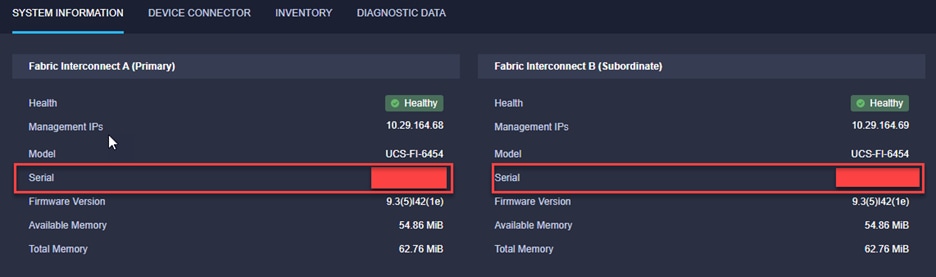
Step 2. Click the Device Connector tab in the console.
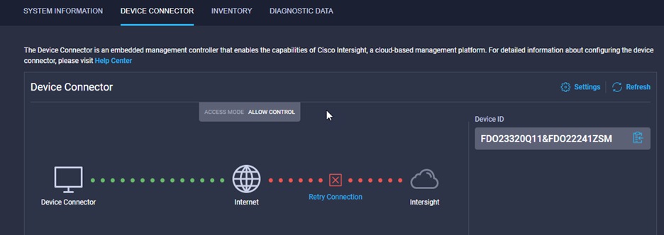
Note: if a Proxy server is needed, the configuration is located under the Settings  menu.
menu.
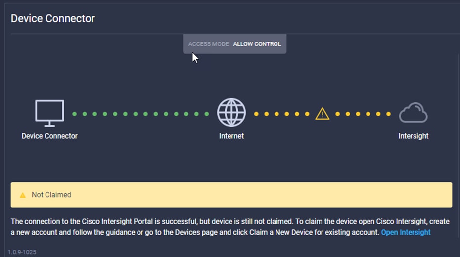
Step 3. Open Cisco Intersight, click Admin > Targets
Step 4. Select Cisco UCS Domain (Intersight Managed) and click Start.
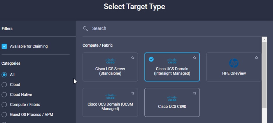
Step 5. Copy the Device ID from the Fabric Interconnect Console and copy it to the Device ID field in Intersight.
Step 6. Copy the Claim Code from the Fabric Interconnect Console and copy it to the Claim Code field in Intersight.
Step 7. Click Claim.
Step 8. From the Cisco Intersight window, click ![]() and then click Licensing. If this is a new account, all servers connected to the UCS Domain will appear under the Base license Tier. If you have purchased Cisco Intersight licenses and have them in your Cisco Smart Account, click Register and follow the prompts to register this Cisco Intersight account to your Cisco Smart Account. Cisco Intersight also offers a one-time 90-day trial of Premier licensing for new accounts. Click Start Trial and then Start to begin this evaluation. The remainder of this section will assume Premier licensing.
and then click Licensing. If this is a new account, all servers connected to the UCS Domain will appear under the Base license Tier. If you have purchased Cisco Intersight licenses and have them in your Cisco Smart Account, click Register and follow the prompts to register this Cisco Intersight account to your Cisco Smart Account. Cisco Intersight also offers a one-time 90-day trial of Premier licensing for new accounts. Click Start Trial and then Start to begin this evaluation. The remainder of this section will assume Premier licensing.
Step 9. From the Licensing Window, click Set Default Tier. From the drop-down list select Premier for Tier and click Set.
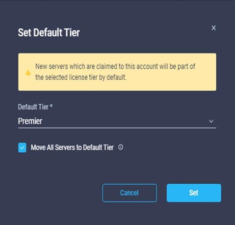
Step 10. 9. Click Refresh to refresh the Intersight window with Premier, Advantage, and Essentials features added.
Cisco Intersight-based Cisco UCS Infrastructure Upgrade
Cisco Intersight can be used to upgrade Cisco UCS Managed Infrastructure. This procedure demonstrates an Intersight-based upgrade of a Cisco UCS Infrastructure (Cisco UCS Manager, fabric interconnects, and IOM modules) from software release 4.1(3b) to 4.2(1f).
Procedure 1. Upgrade Cisco UCS infrastructure using Cisco Intersight
Step 1. To start the upgrade, select OPERATE > Fabric Interconnects. To the right of one of the fabric interconnects that you want to upgrade, click … and select Upgrade Firmware.
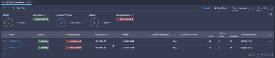
Step 2. Click Start.
Step 3. Ensure the UCS Domain you want to upgrade is shown and selected and click Next.
Note: If you receive this error message go back in the process and Enable “Advanced Mode” and disable “Fabric Evacuation.”
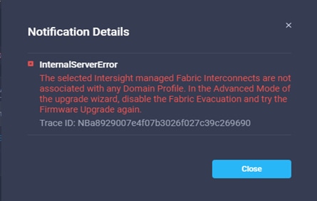
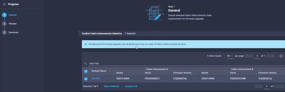
Step 4. Select Version 4.2(1i), select “Advanced Mode, uncheck ”Fabric Interconnect Traffic Evacuation” and click Next.
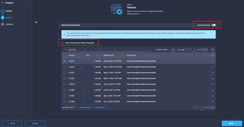
Step 5. Click Upgrade then click Upgrade again to bring up the window allowing you to log in to retrieve software.
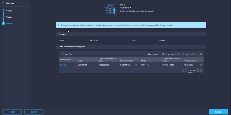
Note: It may be necessary to click Upgrade again to bring up the window allowing you to log in to retrieve software. Login with Cisco ID and password and click Submit.
Step 6. Click Requests, then click the Upgrade Firmware request.
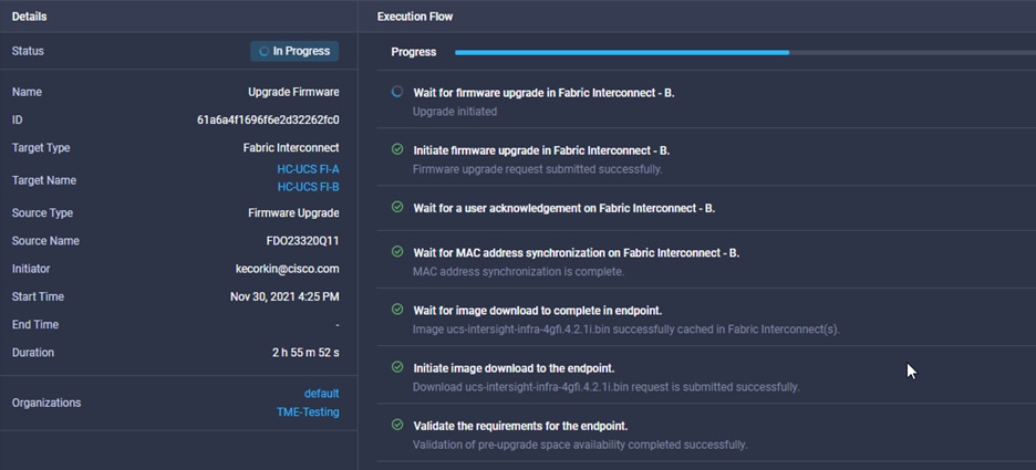
Step 7. While the Cisco UCS Manager and the subordinate fabric interconnect are in the process of upgrading, click Continue and then click Continue again to continue the upgrade.
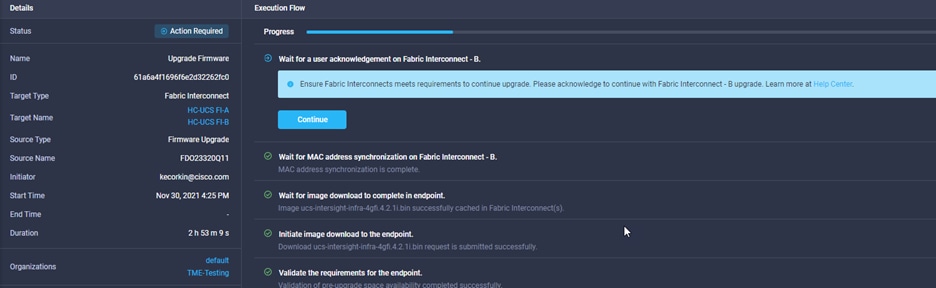
Step 8. When the upgrade completes, the Status will show Success. M6 servers can now be inserted in the chassis or attached to the FIs. Other servers will be upgraded by the Host Firmware Package setting.
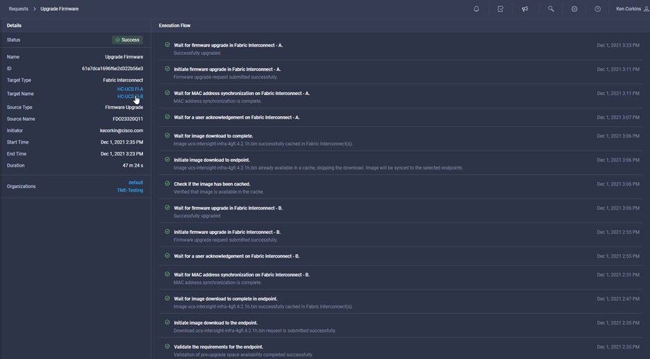
Step 9. From here, proceed to Terraform Automation Workflow if you plan to utilize Terraform to deploy the Cisco UCS resources, or skip to Cisco UCS Manual Configuration if you intend to perform the configuration manually.
Terraform Automation Workflow and Solution Deployment
If using the published Terraform scripts to configure the FlexPod infrastructure, complete this section of the document. If completing a manual configuration, skip to the next section of the document. The Terraform automated FlexPod solution uses a management workstation (control machine) to run Terraform scripts to configure Cisco UCS servers into Cisco Intersight.
Figure 54 illustrates the FlexPod solution implementation workflow which is explained in the following sections. The FlexPod infrastructure layers are first configured in the order illustrated.
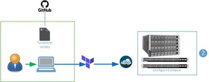
Terraform Cisco UCS Domain Configuration
The configuration of the Cisco UCS Domain using Terraform is divided into two sections:
1. Create Domain Profile
2. Deploy Domain Profile
These two steps require configuration of various variables in files located within each subdirectory of the Terraform repository.
Procedure 1. Create UCS Domain Profile from the Terraform Management Workstation
Step 1. Move to the Create_DomainProfile directory of the repository FlexPod-for-EHR/Terraform/
Step 2. Edit the following variable file to ensure proper variables are entered: terraform.tfvars
Note: It is critical when entering the variable files that consistency is maintained between the Terraform scripts and Ansible scripts.
Step 3. From Create_DomainProfile directory, run the following Terraform commands;
terraform init
Note: This command will initialize the directory structure and download the Intersight provider information from the Terraform Registry.
Step 4. Once the initialization is complete, run the following command;
terraform plan
Note: Terraform plan creates an execution plan based on the configuration files. It does not actually carry out the instructions to Intersight. Once the plan stage has completed, review the output to determine if any errors need to be corrected prior to applying the configuration.
Step 5. If the plan appears to be correct, run the following command;
terraform apply
Step 6. Respond “yes” when Terraform asks; “Do you want to perform these actions?”
Note: Terraform apply performs the actual configuration of the infrastructure in Cisco Intersight. This can be verified by clicking Configure > Profiles > UCS Domain Profiles. At this point, the profile is created by not Deployed.
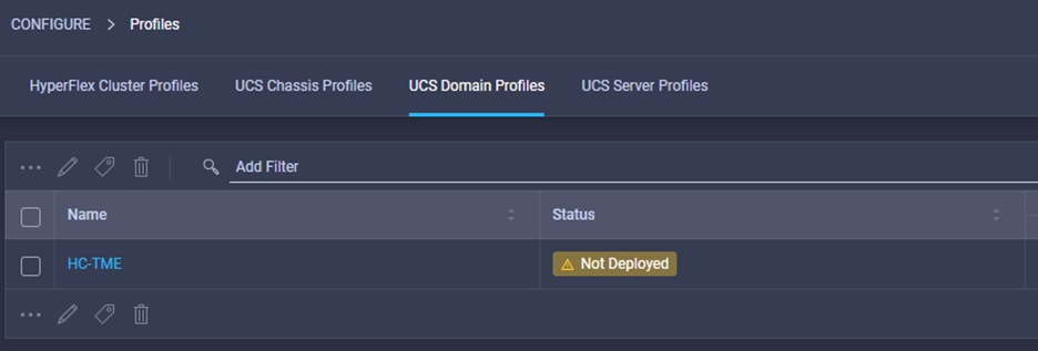
You will deploy the profile in the next section.
Procedure 2. Deploy Domain Profile
Step 1. Move to the Deploy_DomainProfile directory of the repository
Step 2. Edit the following variable file to ensure proper variables are entered:
terraform.tfvars
Note: This file can be used to “Deploy” or “Unassign” the Domain profile by simply changing the variable and running terraform plan and terraform apply.
Step 3. From Create_DomainProfile directory, run the following Terraform commands:
terraform init
Note: This command will initialize the directory structure and download the Intersight provider information from the Terraform Registry.
Step 4. Once the initialization is complete, run the following command:
terraform plan
Note: Terraform plan creates an execution plan based on the configuration files. It does not actually carry out the instructions to Intersight. Once the plan stage has completed, review the output to determine if any errors need to be corrected prior to applying the configuration.
Step 5. If the plan appears to be correct, run the following command:
terraform apply
Step 6. Respond “yes” when Terraform asks; “Do you want to perform these actions?”
Note: Terraform apply performs the actual configuration of the infrastructure in Cisco Intersight. This can be verified by clicking on Configure > Profiles > UCS Domain Profiles. At this point, the profile is Deployed.
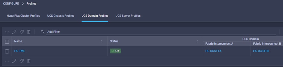
Note: This step can take time to complete.
Cisco UCS Server Configuration
The creation of Cisco UCS Server profiles is divided into two boot modes, local-boot (M.2) or Boot-from-SAN (FC). Each mode offers the ability to create Server Templates which can be used to derive profiles, or to create Server Profiles (without the creating templates.) Refer to Table 11 for clarification of required scripts. The choice is left to the customer. In either case, the unused directories can be deleted from the local automation repository.
Table 11. Terraform Scripts for Cisco UCS Server Configuration
|
|
SAN (fc) Boot |
Local (m.2) Boot |
| Profiles |
Create SAN-Boot_Profiles |
Create Local-Boot_Profiles |
|
|
Deploy SAN-Boot_Profiles |
Deploy Local-Boot_Profiles |
| Templates |
Create SAN-Boot_Templates |
Create_Local-Boot_Templates |
Procedure 1. Create UCS Server Profiles from the Terraform Management Workstation
Step 1. Move to the Create_SAN-Boot_Server_Profiles directory of the repository FlexPod-for-EHR/Terraform/
Step 2. Edit the following variable file to ensure proper variables are entered:
terraform.tfvars
Note: Obtain the WWPN and Boot device names from the NetApp Storage Array.
Step 3. From Create_SAN-Boot_Server_Profiles directory, run the following Terraform commands:
terraform init
Note: This command will initialize the directory structure and download the Intersight provider information from the Terraform Registry.
Step 4. Once the initialization is complete, run the following command:
terraform plan
Note: Terraform plan creates an execution plan based on the configuration files. It does not actually carry out the instructions to Intersight. Once the plan stage has completed, review the output to determine if any errors need to be corrected prior to applying the configuration.
Step 5. If the plan appears to be correct, run the following command:
terraform apply
Step 6. Respond “yes” when Terraform asks; “Do you want to perform these actions?”
Note: Terraform apply performs the actual configuration of the infrastructure in Cisco Intersight. This can be verified by clicking on Configure > Profiles > UCS Domain Profiles. At this point, the profile is created by not Deployed.
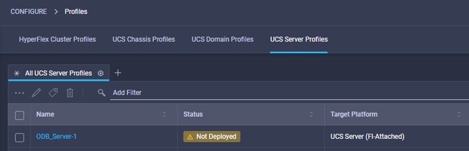
You will deploy the profile in the next section.
Procedure 2. Deploy UCS Server Profiles from the Terraform Management Workstation
Step 2. Edit the following variable file to ensure proper variables are entered:
terraform.tfvars
Note: This file can be used to “Deploy” or “Unassign” the Domain profile by simply changing the variable and running terraform plan and terraform apply.
Step 3. From Deploy_SAN-Boot_Server_Profiles directory, run the following Terraform commands:
terraform init
Note: This command will initialize the directory structure and download the Intersight provider information from the Terraform Registry.
Step 4. Once the initialization is complete, run the following command:
terraform plan
Note: Terraform plan creates an execution plan based on the configuration files. It does not actually carry out the instructions to Intersight. Once the plan stage has completed, review the output to determine if any errors need to be corrected prior to applying the configuration.
Step 5. If the plan appears to be correct, run the following command:
terraform apply
Step 6. Respond “yes” when Terraform asks; “Do you want to perform these actions?”
Note: Terraform apply performs the actual configuration of the infrastructure in Cisco Intersight. This can be verified by clicking on Configure > Profiles > UCS Server Profiles. At this point, the profile is Deployed.
Note: This step can take time to complete.
Procedure 3. Create UCS Server Templates from the Terraform Management Workstation
Step 1. Move to the Create_SAN-Boot_Server_Templates directory of the repository FlexPod-for-EHR/Terraform
Step 2. Edit the following variable file to ensure proper variables are entered:
terraform.tfvars
Note: Obtain the WWPN and Boot device names from the NetApp Storage Array.
Step 3. From Create_SAN-Boot_Server_Templates directory, run the following Terraform commands:
terraform init
Note: This command will initialize the directory structure and download the Intersight provider information from the Terraform Registry.
Step 4. Once the initialization is complete, run the following command:
terraform plan
Note: Terraform plan creates an execution plan based on the configuration files. It does not actually carry out the instructions to Intersight. Once the plan stage has completed, review the output to determine if any errors need to be corrected prior to applying the configuration.
Step 5. If the plan appears to be correct, run the following command:
terraform apply
Step 6. Respond “yes” when Terraform asks; “Do you want to perform these actions?”
Note: Terraform apply performs the actual configuration of the infrastructure in Cisco Intersight. This can be verified by clicking on Configure > Profiles > UCS Domain Profiles. At this point, the profile is created by not Deployed.
Procedure 4. Derive UCS Server Profiles from Templates
Note: Currently, there is no Terraform module to automate creation of Profiles from Templates.
Step 1. From the Server profile template Summary screen, click Derive Profiles.
Note: This action can also be performed later by navigating to Templates, clicking “…” next to the template name and selecting Derive Profiles.
Step 2. Under the Server Assignment, select Assign Now and select Cisco UCS X210c M6 servers. Customers can select one or more servers depending on the number of profiles to be deployed.
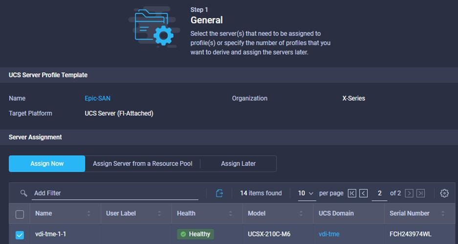
Note: Alternately, you can derive multiple profiles and assign servers later.
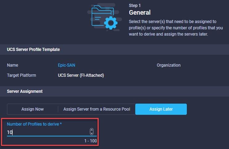
Step 3. Click Next.
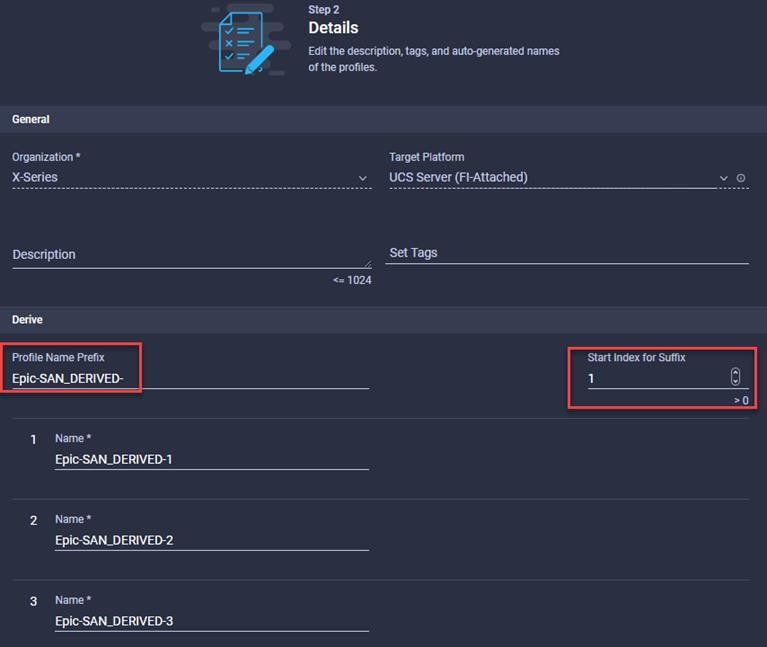
Step 4. Adjust the names and Start Index for Suffix as desired.
Step 5. Click Next.
Step 6. Review the resulting Profiles and Server assignments and click Derive.
Cisco UCS Manual Configuration
Create a Cisco UCS Domain Profile
First you need to create a Cisco UCS domain profile to configure the fabric interconnect ports and discover connected chassis. A domain profile is composed of several policies. Table 12 lists the policies required for the solution described in this document.
Table 12. Policies required for domain profile
| Policy |
Description |
| Multicast policy for each VLAN policy |
allow/disallow IGMP snooping |
| VLAN Policy |
Allowed VLANs, Native VLAN |
| VSAN configuration policy for fabric A |
VSAN Name, ID |
| VSAN configuration policy for fabric B |
VSAN Name, ID |
| Port configuration policy for fabric A |
Server links, Uplinks and Port-Channels |
| Port configuration policy for fabric B |
Server links, Uplinks and Port-Channels |
| System QoS Policy |
Jumbo Frame support, QoS settings |
| Optional Policies |
|
| Network Time Protocol (NTP) policy |
Time zone and NTP server configuration |
| Syslog |
Syslog Sev. And server settings |
| Network Connectivity |
DNS settings |
| SNMP |
Simple Network Management Protocol settings |
| Switch Control |
Switching modes, MAC aging time, and so on. |
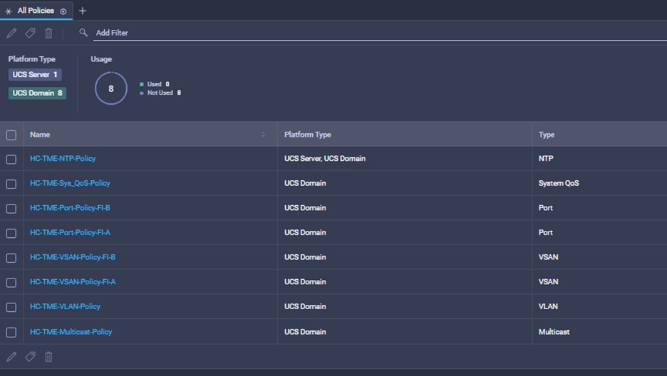
Procedure 1. Create a Cisco UCS Domain Profile
Step 1. Create the Multicast policy:
a. Under Policies, select Create Policy. Then click Multicast.
b. Select the Organization (if one is in use)
c. Give the policy a name (for example, Multicast_Policy)
Note: Each VLAN can have a separate Multicast Policy, or you can use the same policy on all VLANs.
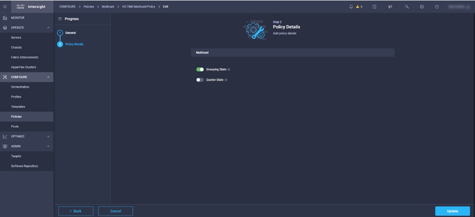
d. Move the selectors to indicate the policy desired
Step 2. Create the VLAN configuration policy:
a. Under Policies, select Create Policy. Then select VLAN and give the VLAN a name (for example, VLAN_Config_Policy).
b. Click Add VLANs to add your required VLANs.
c. Click Multicast Policy to add the multicast policy you just created for your VLAN policy.
d. Click Create.
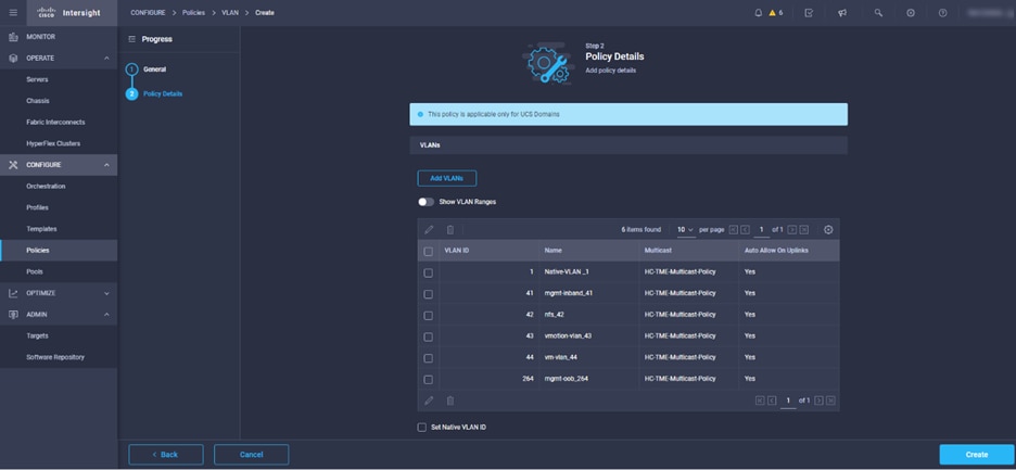
Note: If you will be using the same VLANs on fabric interconnect A and fabric interconnect B, you can use the same policy for both.
Step 3. Create the VSAN configuration policy:
a. Under Policies, select Create Policy. Then select VSAN and give the VSAN a name (for example, VSAN_Config_Policy_A).
b. Click Add VSAN and add the required VSAN names and IDs.
c. Add the corresponding FCoE VLAN ID.
Note: According to best practices, the VSAN IDs should be different for each fabric, so you should create two separate policies.
Step 4. Create the Port Configuration policy:
a. Under Policies, select Create Policy.
b. Select Port and Start.
c. Give the port policy a name.
d. Click Next.
e. To configure Converged Ports, use the slider to define Fibre Channel ports. Click Next.
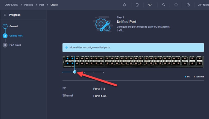
f. Define the port roles: server ports for chassis and server connections, Fibre Channel ports for SAN connections, or network uplink ports.
g. Select ports 1 through 4 and click Configure.
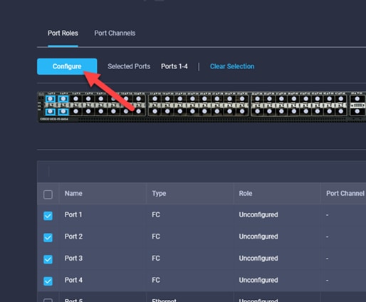
h. From the drop-down list, select FC Uplink and define the admin speed and VSAN ID (the solution described here uses 32 GBps for the speed and VSAN ID 111 for fabric interconnect A and 112 for fabric interconnect B).
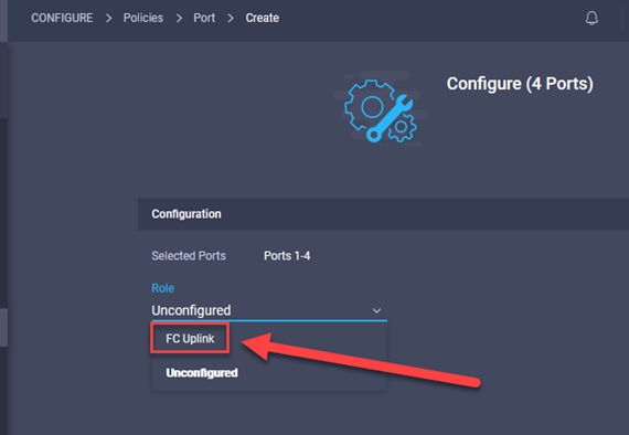
i. To configure server ports, select the ports that have chassis or rack-mounted servers plugged into them and click Configure. From the drop-down list, select Server.
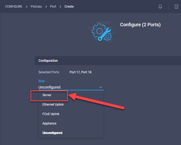
j. To configure network uplink ports, select the ports connected to the upstream network switches and click Configure. From the drop-down list, select Ethernet Uplink.
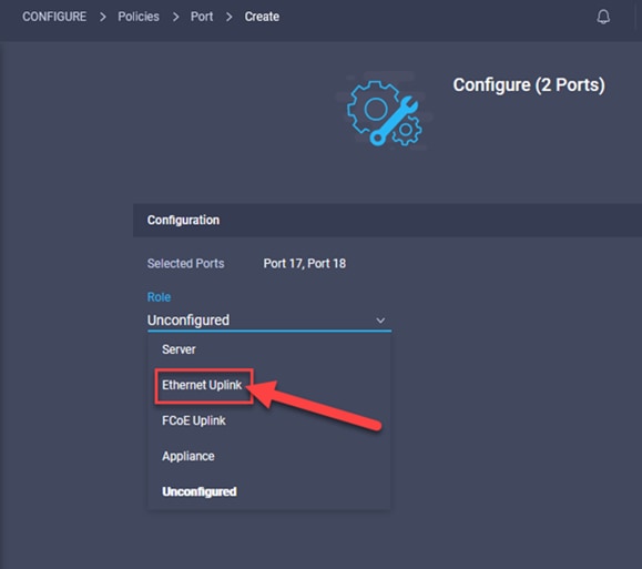
k. To configure Port-Channels, select unconfigured ports, select Create Port Channel.
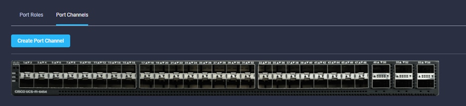
l. Select “Ethernet Uplink Port Channel.
m. Enter the Port-Channel ID and admin speed.
n. Additional policies can be created and applied as needed.
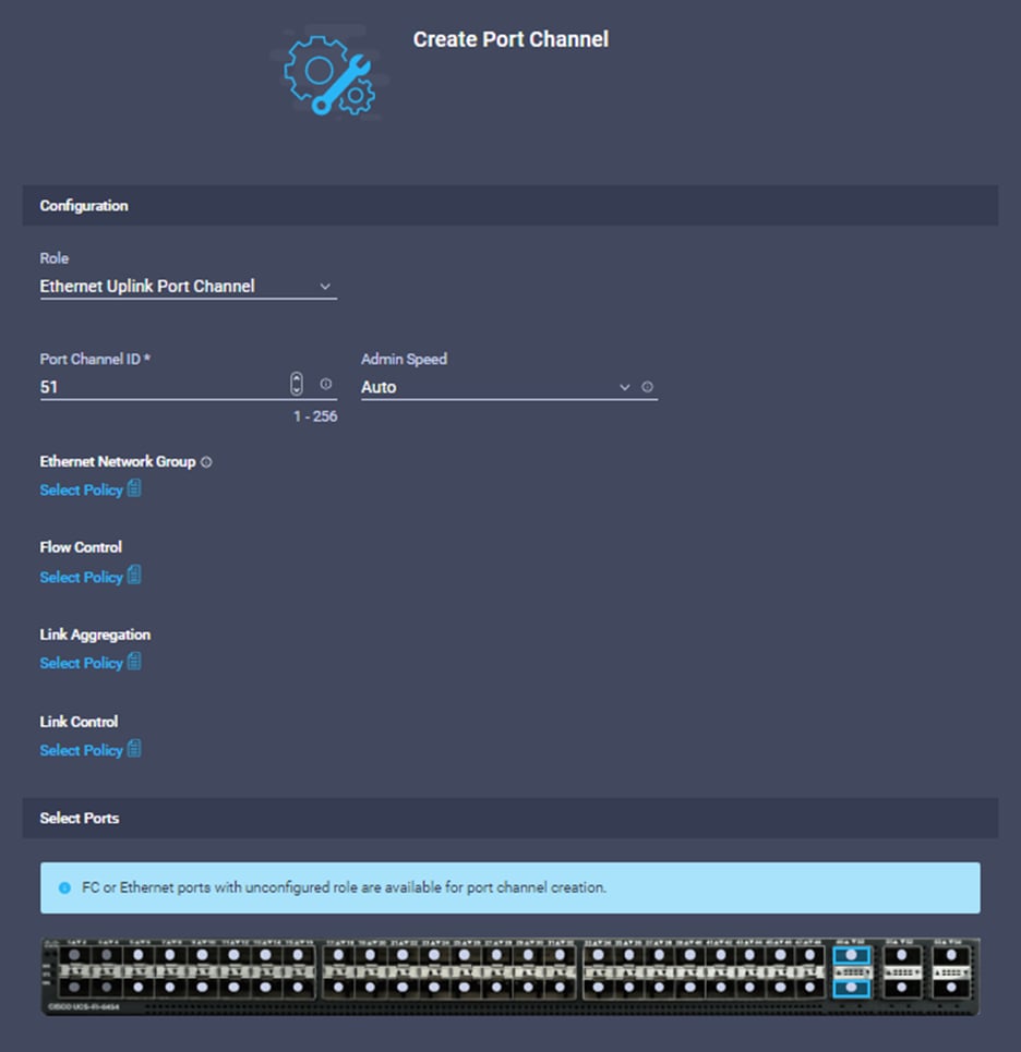
o. Click Save to save the port policy.
Step 5. Repeat steps 1 – 4 to create a port policy for Fabric Interconnect B.
Step 6. Create the NTP policy:
a. Under Policies, select Create Policy.
b. Select NTP and Start.
c. Give the NTP policy a name.
d. Click Next.
e. Define the name or IP address for the NTP servers.
f. Define the correct time zone.
g. Click Create.
Step 7. (Optional) Create the syslog policy:
a. Under Policies, select Create Policy.
b. Select Syslog and Start.
c. Give the syslog policy a name.
d. Click Next.
e. Define the syslog severity level that triggers a report.
f. Define the name or IP address for the syslog servers.
g. Click Create.
Note: You do not need to enable the syslog server.
Step 8. Create the Domain Profile:
a. Click Profiles in the side menu.
b. Select UCS Domain Profiles at the top of the screen.
c. Click Create UCS Domain Profile.

d. Give the profile a name (for example, HC-UCS) and click Next.
e. Select the fabric interconnect domain pair created when you claimed your fabric interconnects.
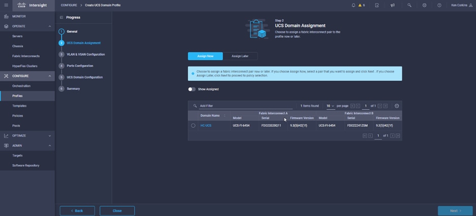
f. Under VLAN & VSAN Configuration, click Select Policy to select the policies created earlier. (Be sure that you select the appropriate policy for each side of the fabric.)
g. Under Ports Configuration, select the port configuration policies created earlier. (Be sure to assign the correct fabric policy to the appropriate side: that is, assign port_FIA to fabric interconnect A and assign port_FIB to fabric interconnect B)
h. Under UCS Domain Configuration, select all the policies you created earlier.
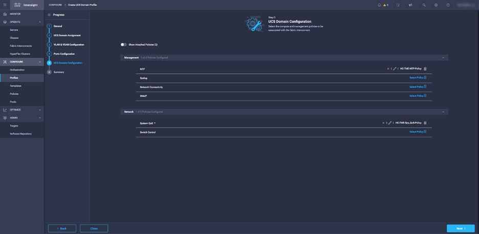
i. Click Next.
j. Click Deploy.
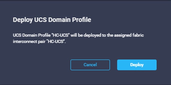
Create a Cisco UCS Server Profile
Much like Cisco UCS Manager, Cisco Intersight managed mode lets you to deploy server profiles that consist of a series of pools and policies. This capability allows detailed management of the entire environment.
Pools used in a Server Profile
Some Cisco UCS Server Profiles are made up of values derived from pools that are assigned to devices and used to build a server profile. Table 13 lists the Pools required for UCS servers in this CVD.
Table 13. List of Required Pools
| Pool |
Description |
| WWNN Pool |
A collection of WWN addresses that can be allocated to VHBAs of a Server Profile |
| WWPN Pool |
A collection of WW Port Name addresses that can be allocated to VHBAs of a Server Profile |
| NVME Pool |
A collection of WWPN addresses used for NMVe Initiators of the VHBA of a server Profile |
| MAC Pool |
A collection of MAC addresses that can be allocated to VNICs of a server profile. |
| IP Pool |
A collection of IPv4 and/or IPv6 addresses that can be allocated to other configuration entities like server profiles |
Procedure 1. Create Required Pools
Step 1. Create two MAC address pools: one for fabric A and one for fabric B.
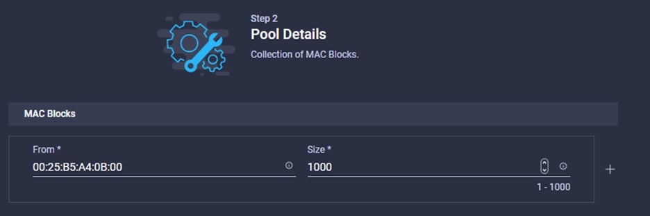
Step 2. Create a WWNN Pool.
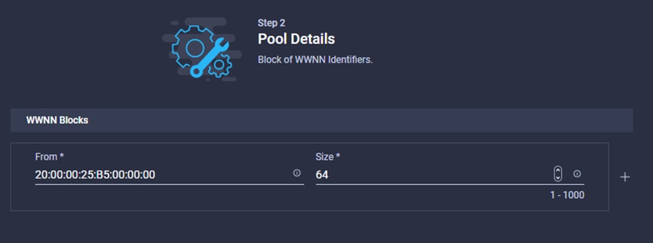
Step 3. For Boot from FC, create two FC WWPN Pools, one for fabric A, one for fabric B.
Note: If you’re not utilizing Boot-from-SAN, skip this step.
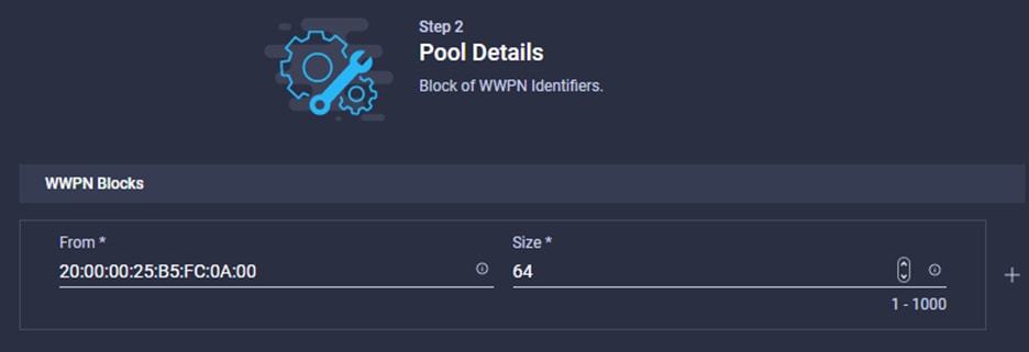
Step 4. For Shared Storage access (NVMe), create two WWPN Pools, one for Fabric A, one for Fabric B

Step 5. Create two IP Pools for IMC Access. One pool uses IP addresses from the [IB-MGMT] range, the second pool uses IP addresses from the [OOB-MGMT] range.
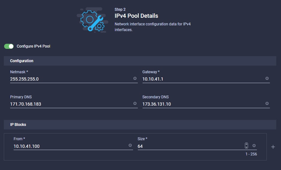
Table 14 lists the policies that make up a server profile.
Table 14. Server Profile Policies
| Policy |
|
| Compute Configuration |
|
|
|
BIOS |
|
|
Boot Order |
|
|
Power |
|
|
Virtual Media |
| Management Configuration |
|
|
|
IMC Access |
|
|
IPMI Over LAN |
|
|
Local User |
|
|
Serial Over LAN |
|
|
SNMP |
|
|
Syslog |
|
|
Virtual KVM |
| Storage Configuration |
|
|
|
SD Card |
|
|
Storage |
| Network Configuration Policies |
|
|
|
LAN Connectivity |
|
|
SAN Connectivity |
| Policies Needed by Other Policies |
|
|
|
Fibre Channel Network (A/B) |
|
|
Fibre Channel Adapter |
|
|
Fibre Channel QoS |
|
|
Ethernet Network Group Policy |
|
|
Ethernet Network Control Policy |
|
|
Ethernet QoS Policy |
|
|
Ethernet Adapter Policy |
Procedure 2. Create Supporting Policies
Step 1. Create two Fibre Channel Network Policies. One for Fabric A and one for Fabric B. Be sure to select UCS Server (FI-Attached) and enter the VSAN ID for each fabric.
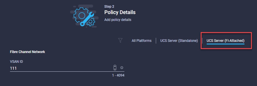
Step 2. Create a Fibre Channel Adapter Policy:
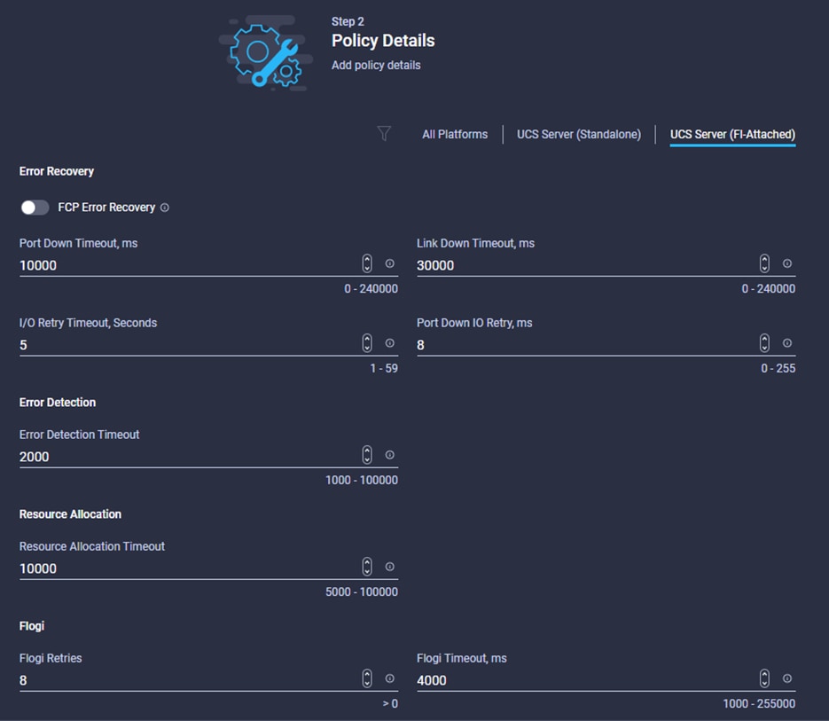
a. Based on Epic performance guidance, increase the I/O Throttle Count to 1024
b. Set the LUN Queue Depth to 254
c. For NVME initiator, set the SCSI I/O queues to 16
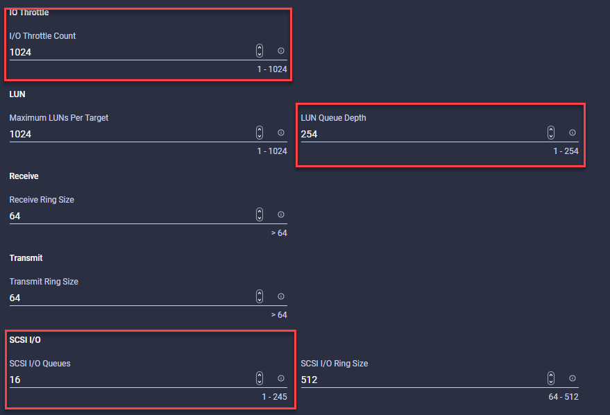
Step 3. Create a Fibre Channel QoS Policy:
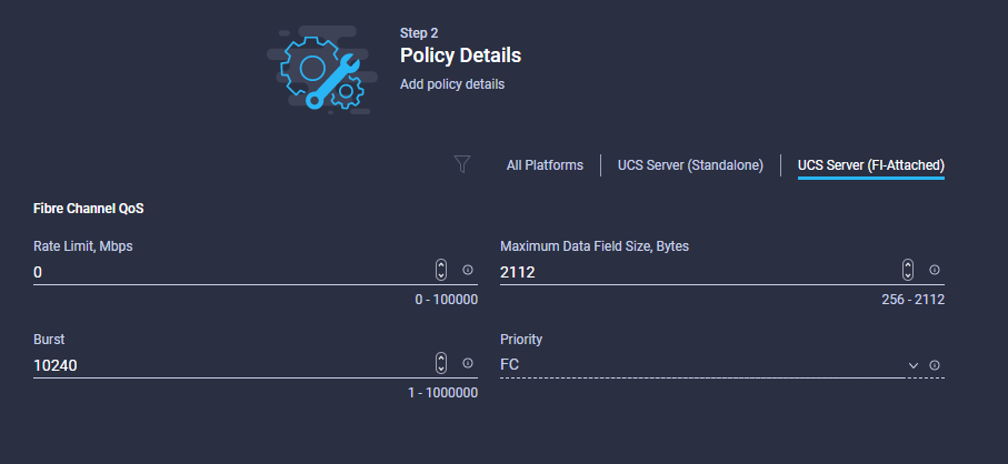
a. Ethernet Network Group Policy. Ensure the listed VLANs match the VLANs in the UCS domain profile.
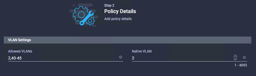
b. Ethernet Network Control Policy:
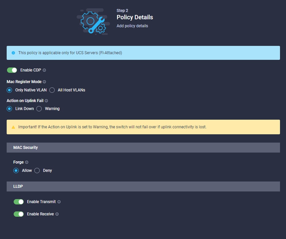
c. Ethernet QoS Policy (ensure the MTU is set to 9000):
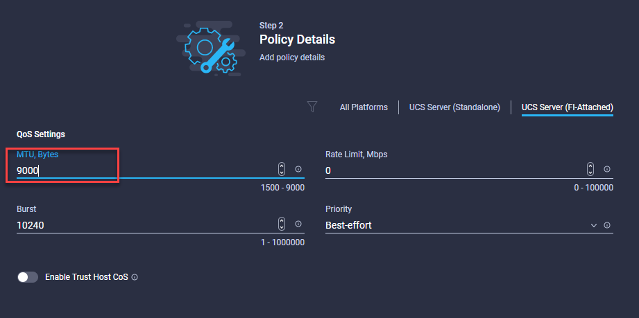
d. Ethernet Adapter Policy:
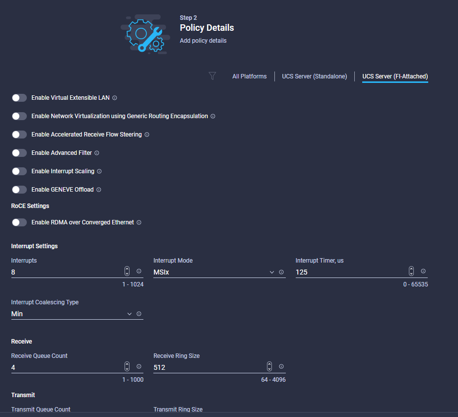
Step 4. For local-boot, create an SD Card Policy.
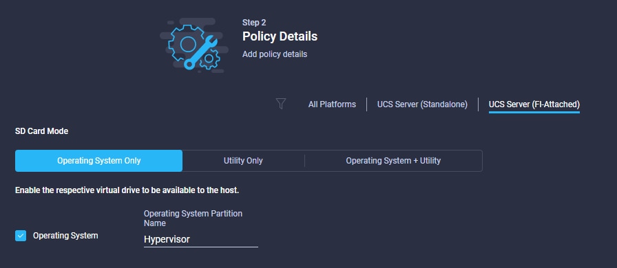
Procedure 3. Configure BIOS Policy
Step 1. Click Select Policy next to BIOS and in the pane on the right, click Create New.
Step 2. Verify correct organization is selected from the drop-down list and provide a name for the policy (for example, HC-BIOS-Policy).
Step 3. Click Next.
Step 4. On the Policy Details screen, select the appropriate values for the BIOS settings. In this deployment, the BIOS values were selected based on recommendations from Epic and in the performance tuning guide for Cisco UCS M6 BIOS: https://www.cisco.com/c/en/us/products/collateral/servers-unified-computing/ucs-b-series-blade-servers/performance-tuning-guide-ucs-m6-servers.html.
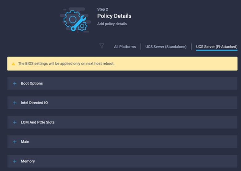
a. LOM and PCIe Slot > CDN Support for LOM: Enabled
b. Processor > Enhanced CPU performance: Auto
c. Memory > NVM Performance Setting: Balanced Profile
Step 5. Define a boot order Policy:
a. Add the ability to boot from KVM-mapped ISO
Note: If using FC Boot, values must be obtained from the NetApp Controller.
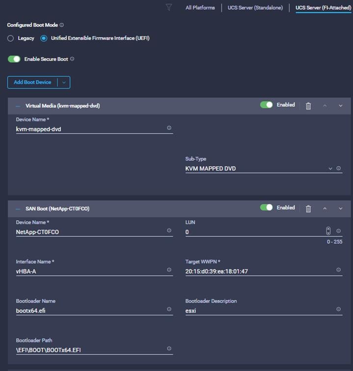
Note: If using local storage (M.2):
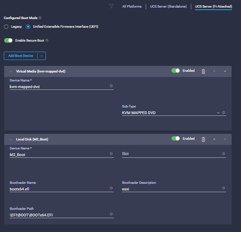
Procedure 4. Create Local User Policy
Step 1. Create a local user policy:
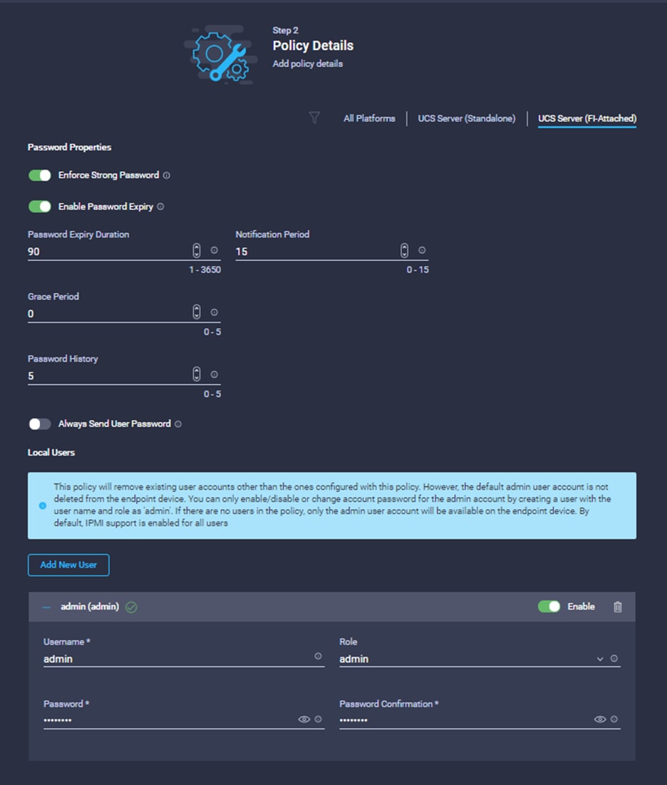
Step 2. Create a Virtual KVM policy:
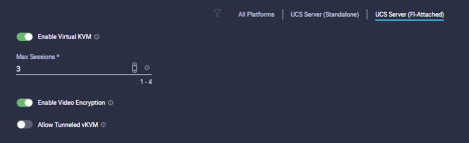
Step 3. Define a boot order policy:
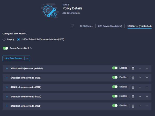
Step 4. Define the Cisco Integrated Management Controller (IMC) Access policy and IP address pool for the keyboard, video, and mouse (KVM):
a. Enter the In-Band Mgmt VLAN ID.
b. Use the In-Band Mgmt and OOB-Mgmt IP pools in the respective slots.
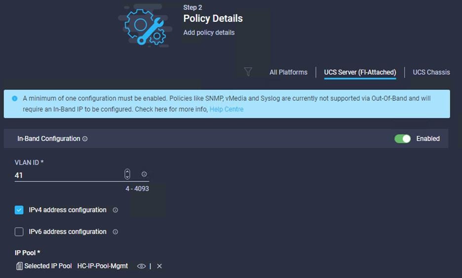
Procedure 5. LAN Connectivity Policy
Note: Epic Best practices suggest creating 2 vNICs for public and management traffic, and 2 vNICs for vMotion traffic.
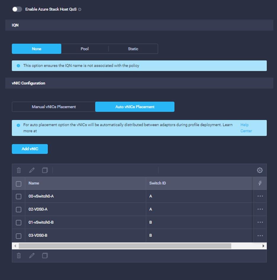
Step 1. For vNIC Configuration, select Auto vNICs Placement.
Step 2. Click Add vNIC. Use the MAC Pools and Policies created earlier as needed.
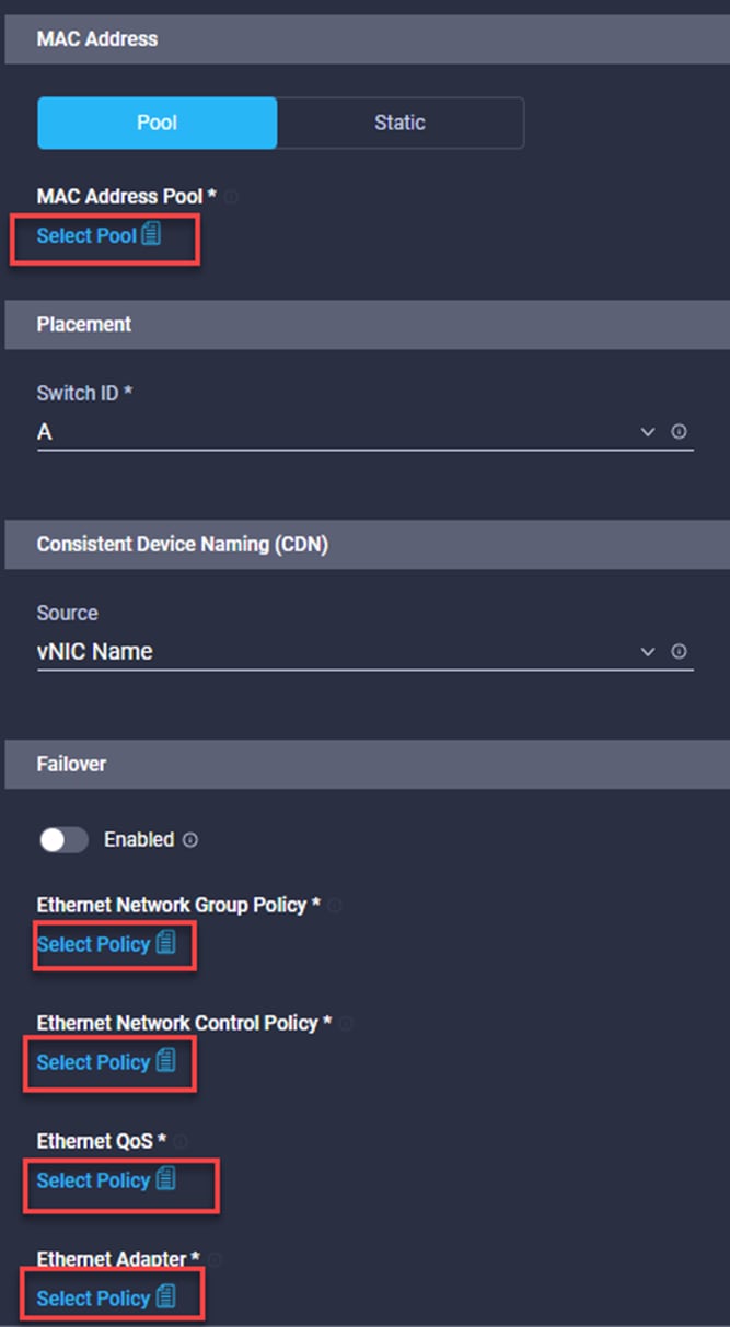
Procedure 6. Create a SAN Connectivity Policy
Note: The required vHBAs will depend on if Boot-From-SAN is in use.
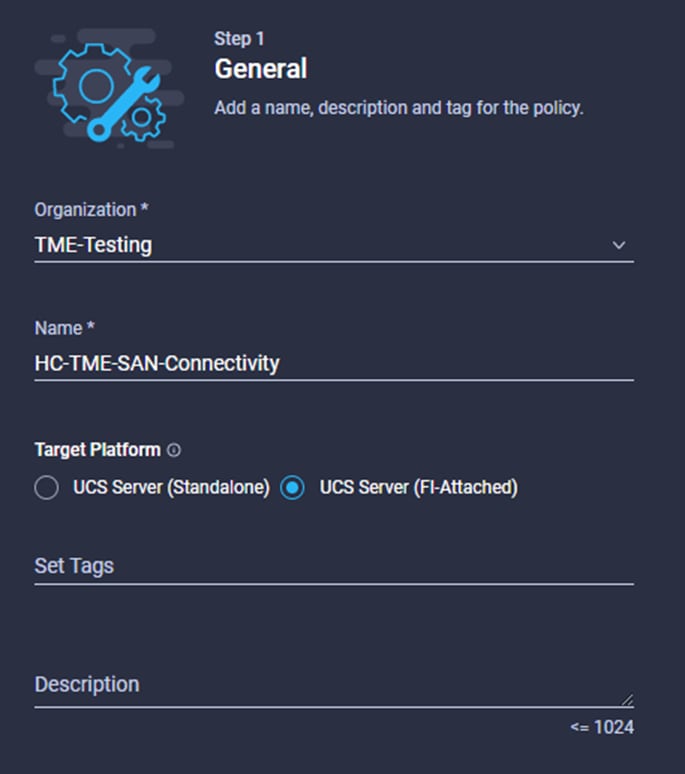
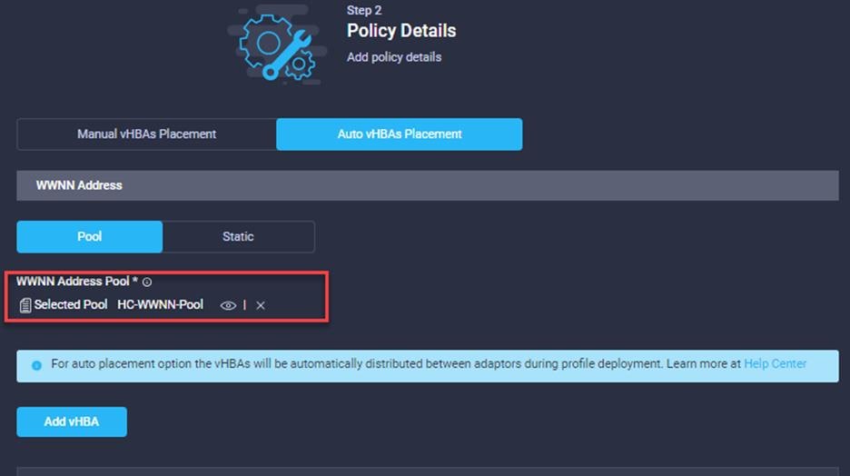
Step 1. Select Auto vHBA Placement then Pool under WWNN Address.
Step 2. Select the WWNN Pool created earlier
Step 3. Click Add vHBA.
Step 4. If using FC Boot-from SAN, create two FC HBAs, one in Fabric A and One in Fabric B.
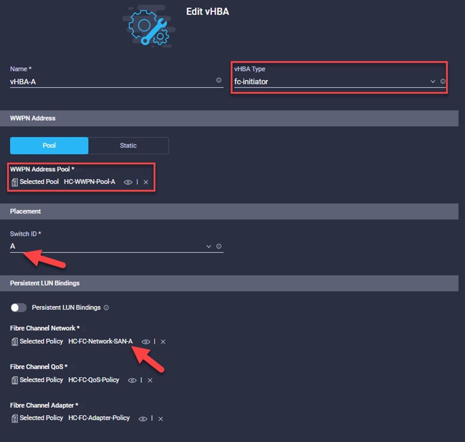
Step 5. Create two NVME HBAs for attaching to the A400 NVME SVMs.
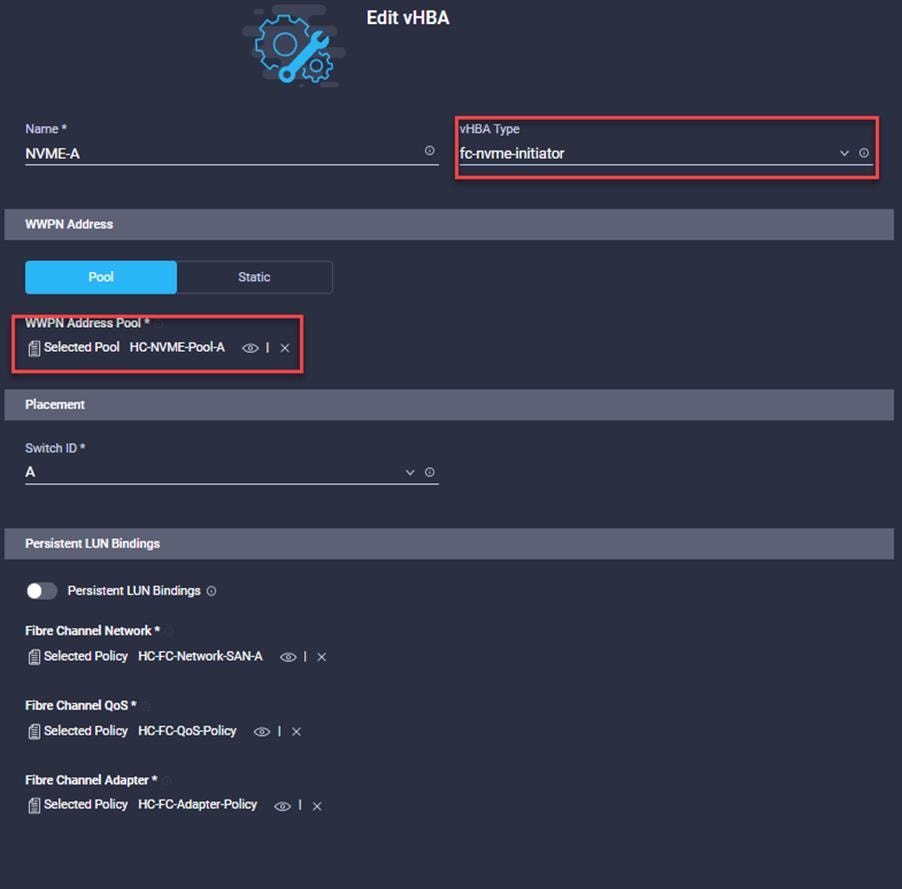
The final SAN Connectivity Policy is shown below:
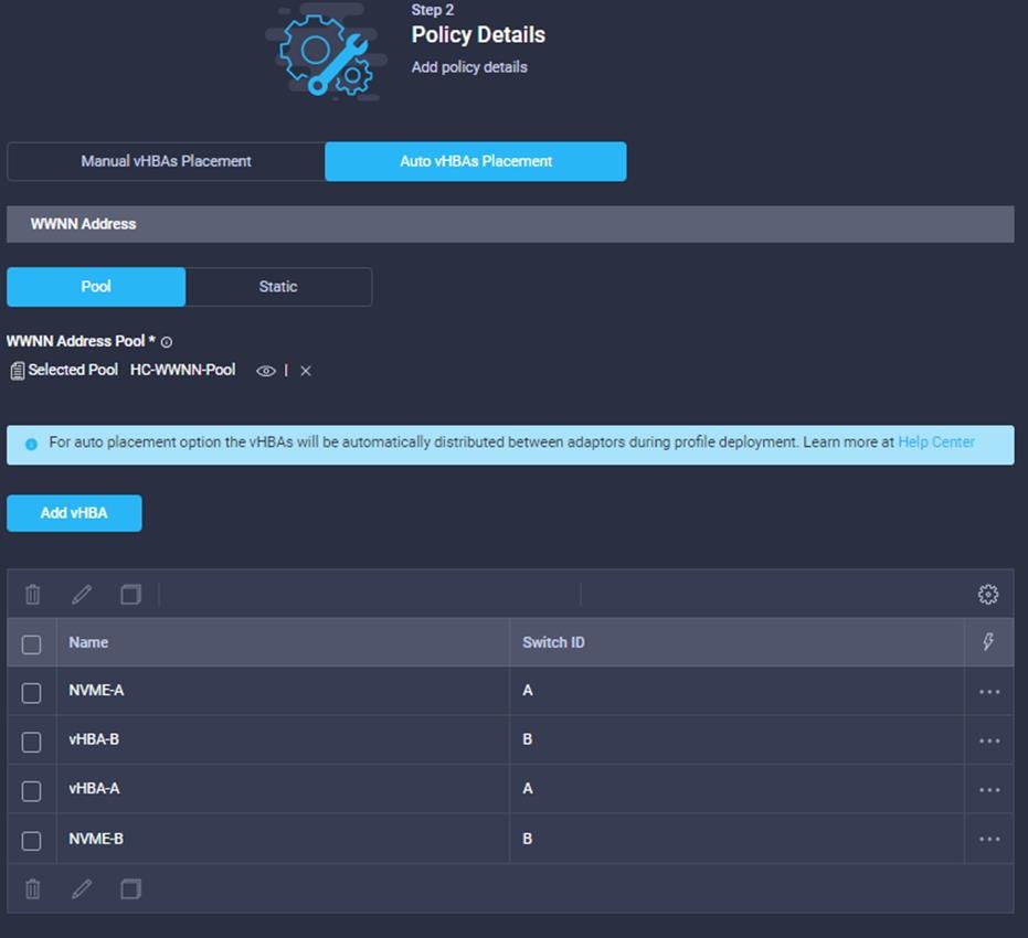
Finalize Cisco UCS Server Profile
After you have created all these polices and pools, step through the Create Server Profile wizard and select each policy or pool as appropriate. After this process is complete, the service profile can be cloned, converted to a template, or directly assigned to a compute node.
SAN Switch Configuration
This section explains how to configure the Cisco MDS 9000s for use in a FlexPod environment. Follow the steps precisely because failure to do so could result in an improper configuration.
Follow the physical connectivity guidelines for FlexPod as explained in section FlexPod Cabling.
The following procedures describe how to configure the Cisco Nexus switches for use in a base FlexPod environment. This procedure assumes you are using the Cisco MDS 9132T with NX-OS 8.4(2c).
Procedure 1. Configure Cisco MDS 9132T A Switch
Note: On initial boot and connection to the serial or console port of the switch, the NX-OS setup should automatically start and attempt to enter Power on Auto Provisioning. Enter y to get to the System Admin Account Setup.
Step 1. Configure the switch using the command line.
---- System Admin Account Setup ----
Do you want to enforce secure password standard (yes/no) [y]: Enter
Enter the password for "admin": <password>
Confirm the password for "admin": <password>
Would you like to enter the basic configuration dialog (yes/no): yes
Create another login account (yes/no) [n]: Enter
Configure read-only SNMP community string (yes/no) [n]: Enter
Configure read-write SNMP community string (yes/no) [n]: Enter
Enter the switch name : <mds-A-hostname>
Continue with Out-of-band (mgmt0) management configuration? (yes/no) [y]: Enter
Mgmt0 IPv4 address : <mds-A-mgmt0-ip>
Mgmt0 IPv4 netmask : <mds-A-mgmt0-netmask>
Configure the default gateway? (yes/no) [y]: Enter
IPv4 address of the default gateway : <mds-A-mgmt0-gw>
Configure advanced IP options? (yes/no) [n]: Enter
Enable the ssh service? (yes/no) [y]: Enter
Type of ssh key you would like to generate (dsa/rsa) [rsa]: Enter
Number of rsa key bits <1024-2048> [1024]: Enter
Enable the telnet service? (yes/no) [n]: Enter
Configure congestion/no_credit drop for fc interfaces? (yes/no) [y]: Enter
Enter the type of drop to configure congestion/no_credit drop? (con/no) [c]: Enter
Enter milliseconds in multiples of 10 for congestion-drop for logical-type edge
in range (<200-500>/default), where default is 500. [d]: Enter
Enable the http-server? (yes/no) [y]: Enter
Configure clock? (yes/no) [n]: Enter
Configure timezone? (yes/no) [n]: Enter
Configure summertime? (yes/no) [n]: Enter
Configure the ntp server? (yes/no) [n]: Enter
Configure default switchport interface state (shut/noshut) [shut]: Enter
Configure default switchport trunk mode (on/off/auto) [on]: auto
Configure default switchport port mode F (yes/no) [n]: yes
Configure default zone policy (permit/deny) [deny]: Enter
Enable full zoneset distribution? (yes/no) [n]: Enter
Configure default zone mode (basic/enhanced) [basic]: Enter
Step 2. Review the configuration.
Would you like to edit the configuration? (yes/no) [n]: Enter
Use this configuration and save it? (yes/no) [y]: Enter
Procedure 2. Configure Cisco MDS 9132T B Switch
To set up the initial configuration for the Cisco MDS B switch, follow these steps:
Note: On initial boot and connection to the serial or console port of the switch, the NX-OS setup should automatically start and attempt to enter Power on Auto Provisioning. Enter y to get to the System Admin Account Setup.
Step 1. Configure the switch using the command line.
---- System Admin Account Setup ----
Do you want to enforce secure password standard (yes/no) [y]: Enter
Enter the password for "admin": <password>
Confirm the password for "admin": <password>
Would you like to enter the basic configuration dialog (yes/no): yes
Create another login account (yes/no) [n]: Enter
Configure read-only SNMP community string (yes/no) [n]: Enter
Configure read-write SNMP community string (yes/no) [n]: Enter
Enter the switch name : <mds-B-hostname>
Continue with Out-of-band (mgmt0) management configuration? (yes/no) [y]: Enter
Mgmt0 IPv4 address : <mds-B-mgmt0-ip>
Mgmt0 IPv4 netmask : <mds-B-mgmt0-netmask>
Configure the default gateway? (yes/no) [y]: Enter
IPv4 address of the default gateway : <mds-B-mgmt0-gw>
Configure advanced IP options? (yes/no) [n]: Enter
Enable the ssh service? (yes/no) [y]: Enter
Type of ssh key you would like to generate (dsa/rsa) [rsa]: Enter
Number of rsa key bits <1024-2048> [1024]: Enter
Enable the telnet service? (yes/no) [n]: Enter
Configure congestion/no_credit drop for fc interfaces? (yes/no) [y]: Enter
Enter the type of drop to configure congestion/no_credit drop? (con/no) [c]: Enter
Enter milliseconds in multiples of 10 for congestion-drop for logical-type edge
in range (<200-500>/default), where default is 500. [d]: Enter
Enable the http-server? (yes/no) [y]: Enter
Configure clock? (yes/no) [n]: Enter
Configure timezone? (yes/no) [n]: Enter
Configure summertime? (yes/no) [n]: Enter
Configure the ntp server? (yes/no) [n]: Enter
Configure default switchport interface state (shut/noshut) [shut]: Enter
Configure default switchport trunk mode (on/off/auto) [on]: auto
Configure default switchport port mode F (yes/no) [n]: yes
Configure default zone policy (permit/deny) [deny]: Enter
Enable full zoneset distribution? (yes/no) [n]: Enter
Configure default zone mode (basic/enhanced) [basic]: Enter
Step 2. Review the configuration.
Would you like to edit the configuration? (yes/no) [n]: Enter
Use this configuration and save it? (yes/no) [y]: Enter
Procedure 3. Configure FlexPod Cisco MDS Ansible Switch
Step 1. Add MDS switch ssh keys to /root/.ssh/known_hosts. Adjust known_hosts as necessary if errors occur.
ssh admin@<mds-A-mgmt0-ip>
exit
ssh admin@<mds-B-mgmt0-ip>
exit
Step 2. Edit the following variable files to ensure proper MDS variables are entered:
● FlexPod-for-EHR/Ansible/inventory
● FlexPod-for-EHR/Ansible/group_vars/all.yml
● FlexPod-for-EHR/Ansible/host_vars/mdsA.yml
● FlexPod-for-EHR/Ansible/host_vars/mdsB.yml
● FlexPod-for-EHR/Ansible/roles/MDSconfig/defaults/main.yml
Note: The FC and FC-NVMe NetApp LIF WWPNs should have already been entered into the all.yml file so that MDS device alias can be properly configured. The Cisco UCS server initiator WWPNs for both FC and FC-NVMe should also be entered into all.yml. To query these WWPNs, log into the Cisco Intersight web interface and select “Configure > Pools >.
Procedure 4. Obtain the WWPNs for NetApp FC LIFs
Step 1. Run the following commands on NetApp cluster management console:
network interface show -vserver Infra-SVM -data-protocol fcp
Procedure 5. Obtain the WWPNs for Cisco UCS Server Profiles
Step 1. From the Intersight GUI, go to: CONFIGURE > Profiles. Select UCS Server Profiles and click [Server Profile Name]. Under General, click SAN Connectivity and find the WWPN information for various vHBAs in the window on the right.
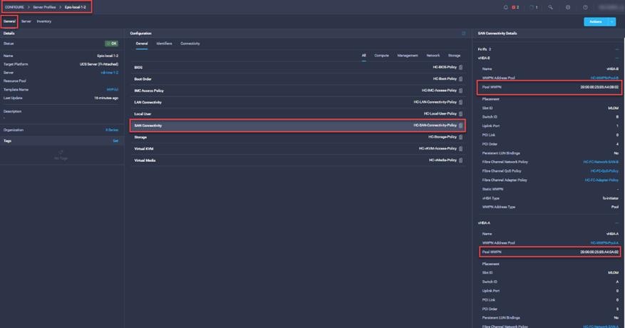
Step 2. Alternately, a list of assigned WWPNs can be found by exporting the values from the WWPN Pools. Select each of the pools, click the Export button to download a .csv file containing the port names and server assignments.
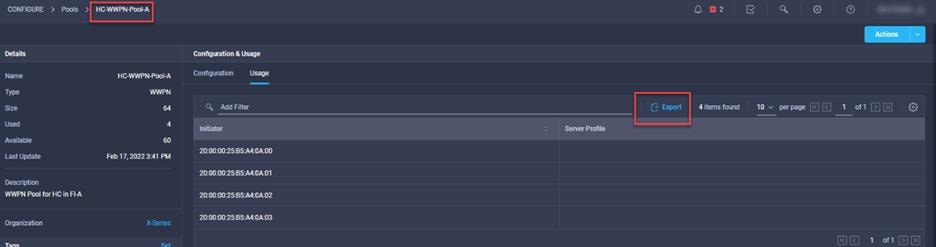
Step 3. From /root/ FlexPod-for-EHR/Ansible, run the Setup_MDS.yml Ansible playbook.
ansible-playbook ./Setup_MDS.yml -i inventory
Step 4. Once the Ansible playbook has been run and configured both switches, it is important to configure the local time so that logging time alignment and any backup schedules are correct. For more information on configuring the timezone and daylight savings time or summertime, please see Cisco MDS 9000 Series Fundamentals Configuration Guide, Release 8.x. Sample clock commands for the United States Pacific timezone are:
clock timezone PST -8 0
clock summer-time PDT 2 Sunday March 02:00 1 Sunday November 02:00 60
Step 5. ssh into each switch and run the following commands:
clock timezone <timezone> <hour-offset> <minute-offset>
clock summer-time <timezone> <start-week> <start-day> <start-month> <start-time> <end-week> <end-day> <end-month> <end-time> <offset-minutes>
FlexPod Cisco MDS Switch Manual Configuration
Procedure 1. Enable Licenses on Cisco MDS 9132T A and Cisco MDS 9132T B
Step 1. Log in as admin.
Step 2. Run the following commands:
configure terminal
feature npiv
feature fport-channel-trunk
Procedure 2. Add NTP Servers and Local Time Configuration on Cisco MDS 9132T A and Cisco MDS 9132T B
Step 1. From the global configuration mode, run the following command:
ntp server <nexus-A-mgmt0-ip>
ntp server <nexus-B-mgmt0-ip>
clock timezone <timezone> <hour-offset> <minute-offset>
clock summer-time <timezone> <start-week> <start-day> <start-month> <start-time> <end-week> <end-day> <end-month> <end-time> <offset-minutes>
Note: It is important to configure the local time so that logging time alignment, any backup schedules, and SAN Analytics forwarding are correct. For more information on configuring the timezone and daylight savings time or summer time, please see Cisco MDS 9000 Series Fundamentals Configuration Guide, Release 8.x. Sample clock commands for the United States Pacific timezone are:
clock timezone PST -8 0
clock summer-time PDT 2 Sunday March 02:00 1 Sunday November 02:00 60
Procedure 3. Configure Individual Ports for Cisco MDS 9132T A
Step 1. From the global configuration mode, run the following commands:
interface fc1/1
switchport description <st-clustername>-1:5a
switchport speed 32000
switchport trunk mode off
no shutdown
exit
interface fc1/2
switchport description \<st-clustername>-2:5a
switchport speed 32000
switchport trunk mode off
no shutdown
exit
interface fc1/5
switchport description <ucs-clustername>-a:1/1
channel-group 15
no shutdown
exit
interface fc1/6
switchport description <ucs-clustername>-a:1/2
channel-group 15
no shutdown
exit
interface port-channel15
channel mode active
switchport trunk allowed vsan <vsan-a-id>
switchport description <ucs-clustername>-a
switchport speed 32000
no shutdown
exit
Note: If VSAN trunking is not being used between the Cisco UCS Fabric Interconnects and the MDS switches, do not enter “switchport trunk allowed vsan ” for interface port-channel15. Also, the default setting of the switchport trunk mode auto is being used for the port channel.
Procedure 4. Configure Individual Ports for Cisco MDS 9132T B
Step 1. From the global configuration mode, run the following commands:
interface fc1/1
switchport description <st-clustername>-1:5b
switchport speed 32000
switchport trunk mode off
no shutdown
exit
interface fc1/2
switchport description <st-clustername>-2:5b
switchport speed 32000
switchport trunk mode off
no shutdown
exit
interface fc1/5
switchport description <ucs-clustername>-b:1/1
channel-group 15
no shutdown
exit
interface fc1/6
switchport description <ucs-clustername>-b:1/2
channel-group 15
no shutdown
exit
interface port-channel15
channel mode active
switchport trunk allowed vsan <vsan-b-id>
switchport description <ucs-clustername>-b
switchport speed 32000
no shutdown
exit
Note: If VSAN trunking is not being used between the Cisco UCS Fabric Interconnects and the MDS switches, do not enter “switchport trunk allowed vsan ” for interface port-channel15. Also, the default setting of the switchport trunk mode auto is being used for the port channel.
Procedure 5. Create VSANs for Cisco MDS 9132T A
Step 1. From the global configuration mode, run the following commands:
vsan database
vsan <vsan-a-id>
vsan <vsan-a-id> name Fabric-A
exit
zone smart-zoning enable vsan <vsan-a-id>
vsan database
vsan <vsan-a-id> interface fc1/1
vsan <vsan-a-id> interface fc1/2
vsan <vsan-a-id> interface port-channel15
exit
Procedure 6. Create VSANs for Cisco MDS 9132T B
Step 1. From the global configuration mode, run the following commands:
vsan database
vsan <vsan-b-id>
vsan <vsan-b-id> name Fabric-B
exit
zone smart-zoning enable vsan <vsan-b-id>
vsan database
vsan <vsan-b-id> interface fc1/1
vsan <vsan-b-id> interface fc1/2
vsan <vsan-b-id> interface port-channel15
exit
Procedure 7. Create Device Aliases for Cisco MDS 9132T A
Step 1. From the global configuration mode, run the following commands:
device-alias mode enhanced
device-alias database
device-alias name Infra_SVM-fcp-lif-01a pwwn <fcp-lif-01a-wwpn>
device-alias name Infra_SVM-fcp-lif-02a pwwn <fcp-lif-02a-wwpn>
device-alias name Infra_SVM-fc-nvme-lif-01a pwwn <fc-nvme-lif-01a-wwpn>
device-alias name Infra_SVM-fc-nvme-lif-02a pwwn <fc-nvme-lif-02a-wwpn>
device-alias name VM-Host-Infra-FCP-01-A pwwn <vm-host-infra-fcp-01-wwpna>
device-alias name VM-Host-Infra-FCP-02-A pwwn <vm-host-infra-fcp-02-wwpna>
device-alias name VM-Host-Infra-FCP-03-A pwwn <vm-host-infra-fcp-03-wwpna>
device-alias name VM-Host-Infra-FCP-04-A pwwn <vm-host-infra-fcp-04-wwpna>
device-alias name VM-Host-Infra-FC-NVMe-01-A pwwn <vm-host-infra-fc-nvme-01-wwpna>
device-alias name VM-Host-Infra-FC-NVMe-02-A pwwn <vm-host-infra-fc-nvme-02-wwpna>
device-alias name VM-Host-Infra-FC-NVMe-03-A pwwn <vm-host-infra-fc-nvme-03-wwpna>
device-alias name VM-Host-Infra-FC-NVMe-04-A pwwn <vm-host-infra-fc-nvme-04-wwpna>
device-alias commit
Procedure 8. Create Device Aliases for Cisco MDS 9132T B
Step 1. From the global configuration mode, run the following commands:
device-alias mode enhanced
device-alias database
device-alias name Infra_SVM-fcp-lif-01b pwwn <fcp-lif-01b-wwpn>
device-alias name Infra_SVM-fcp-lif-02b pwwn <fcp-lif-02b-wwpn>
device-alias name Infra_SVM-fc-nvme-lif-01b pwwn <fc-nvme-lif-01b-wwpn>
device-alias name Infra_SVM-fc-nvme-lif-02b pwwn <fc-nvme-lif-02b-wwpn>
device-alias name VM-Host-Infra-FCP-01-B pwwn <vm-host-infra-fcp-01-wwpnb>
device-alias name VM-Host-Infra-FCP-02-B pwwn <vm-host-infra-fcp-02-wwpnb>
device-alias name VM-Host-Infra-FCP-03-B pwwn <vm-host-infra-fcp-03-wwpnb>
device-alias name VM-Host-Infra-FCP-04-B pwwn <vm-host-infra-fcp-04-wwpnb>
device-alias name VM-Host-Infra-FC-NVMe-01-B pwwn <vm-host-infra-fc-nvme-01-wwpnb>
device-alias name VM-Host-Infra-FC-NVMe-02-B pwwn <vm-host-infra-fc-nvme-02-wwpnb>
device-alias name VM-Host-Infra-FC-NVMe-03-B pwwn <vm-host-infra-fc-nvme-03-wwpnb>
device-alias name VM-Host-Infra-FC-NVMe-04-B pwwn <vm-host-infra-fc-nvme-04-wwpnb>
device-alias commit
Procedure 9. Create Zones and Zonesets on Cisco MDS 9132T A
Step 1. To create the required zones and zonesets on Fabric A, run the following commands:
configure terminal
zone name FCP-Infra_SVM-Fabric-A vsan <vsan-a-id>
member device-alias VM-Host-Infra-FCP-01-A init
member device-alias VM-Host-Infra-FCP-02-A init
member device-alias VM-Host-Infra-FCP-03-A init
member device-alias VM-Host-Infra-FCP-04-A init
member device-alias Infra_SVM-fcp-lif-01a target
member device-alias Infra_SVM-fcp-lif-02a target
exit
zone name FC-NVMe-Infra_SVM-Fabric-A vsan <vsan-a-id>
member device-alias VM-Host-Infra-FC-NVMe-01-A init
member device-alias VM-Host-Infra-FC-NVMe-02-A init
member device-alias VM-Host-Infra-FC-NVMe-03-A init
member device-alias VM-Host-Infra-FC-NVMe-04-A init
member device-alias Infra_SVM-fc-nvme-lif-01a target
member device-alias Infra_SVM-fc-nvme-lif-02a target
exit
zoneset name FlexPod-Fabric-A vsan <vsan-a-id>
member FCP-Infra_SVM-Fabric-A
member FC-NVMe-Infra_SVM-Fabric-A
exit
zoneset activate name FlexPod-Fabric-A vsan \<vsan-a-id>
show zoneset active
copy r s
Note: Since Smart Zoning is enabled, a single zone for each storage protocol (FCP and FC-NVMe) is created with all host initiators and targets for the Infra_SVM instead of creating separate zones for each host with the host initiator and targets. If a new host is added, its initiator can simply be added to each single zone in each MDS switch and then the zoneset reactivated. If another SVM is added to the FlexPod with FC and/or FC-NVMe targets, new zones can be added for that SVM.
Procedure 10. Create Zones and Zonesets on Cisco MDS 9132T B
Step 1. To create the required zones and zoneset on Fabric B, run the following commands:
configure terminal
zone name FCP-Infra_SVM-Fabric-B vsan <vsan-b-id>
member device-alias VM-Host-Infra-FCP-01-B init
member device-alias VM-Host-Infra-FCP-02-B init
member device-alias VM-Host-Infra-FCP-03-B init
member device-alias VM-Host-Infra-FCP-04-B init
member device-alias Infra_SVM-fcp-lif-01b target
member device-alias Infra_SVM-fcp-lif-02b target
exit
zone name FC-NVMe-Infra_SVM-Fabric-B vsan <vsan-b-id>
member device-alias VM-Host-Infra-FC-NVMe-01-B init
member device-alias VM-Host-Infra-FC-NVMe-02-B init
member device-alias VM-Host-Infra-FC-NVMe-03-B init
member device-alias VM-Host-Infra-FC-NVMe-04-B init
member device-alias Infra_SVM-fc-nvme-lif-01b target
member device-alias Infra_SVM-fc-nvme-lif-02b target
exit
zoneset name FlexPod-Fabric-B vsan <vsan-b-id>
member FCP-Infra_SVM-Fabric-B
member FC-NVMe-Infra_SVM-Fabric-B
exit
zoneset activate name FlexPod-Fabric-B vsan <vsan-b-id>
show zoneset active
copy r s
Storage Configuration – ONTAP Boot Storage Setup
This configuration requires information from both the server profiles and NetApp storage system. After creating the boot LUNs, initiator groups and appropriate mappings between the two, Cisco UCS server profiles will be able to see the boot disks hosted on NetApp controllers.
This section provides details about the Ansible Scripts used to configure ONTAP Boot storage.
Procedure 1. Configure the Storage for ONTAP Boot
Step 1. Edit the following variable file and update the fcp_igroups variables:
FlexPod-for-EHR/Ansible/vars/ontap_main.yml
Note: Update the initiator WWPNs for FC igroups.
Step 2. From /root/ FlexPod-for-EHR/Ansible, invoke the ansible scripts for this section using the following command:
ansible-playbook -i inventory Setup_ONTAP.yml -t ontap_config_part_2
Note: Use the -vvv tag to see detailed execution output log.
Procedure 1. Create Boot LUNs for ESXi Servers using NetApp Cluster Management Console
Step 1. Run the following commands to create boot LUNs for all the ESXi servers:
lun create -vserver Infra-SVM -path /vol/esxi_boot/Epic-Host-01 -size 32GB -ostype vmware -space-reserve disabled
lun create -vserver Infra-SVM -path /vol/esxi_boot/Epic-Host-02 -size 32GB -ostype vmware -space-reserve disabled
lun create -vserver Infra-SVM -path /vol/esxi_boot/Epic-Host-03 -size 32GB -ostype vmware -space-reserve disabled
Refer to section Obtain the WWPNs for Cisco UCS Server Profiles to obtain host WWPNs.
Procedure 1. Create Initiator Groups for FC Storage Access using NetApp Cluster Management Console
Step 1. To access boot LUNs, following igroups for individual hosts are created:
lun igroup create -vserver Infra-SVM -igroup Epic-Host-01 -protocol fcp -ostype vmware -initiator <Epic-Host-01-wwpna>, <Epic-Host-01-wwpnb>
lun igroup create -vserver Infra-SVM -igroup Epic-Host-02 -protocol fcp -ostype vmware -initiator <Epic-Host-02-wwpna>, <Epic-Host-02-wwpnb>
lun igroup create -vserver Infra-SVM -igroup Epic-Host-03 -protocol fcp -ostype vmware -initiator <Epic-Host-03-wwpna>, <Epic-Host-03-wwpnb>
Step 2. To view and verify the FC igroups just created, use the following command:
lun igroup show -vserver Infra-SVM -protocol fcp
Step 3. (Optional) To access a common datastore from all the hosts, a common igroup for all the servers can be created as follows:
lun igroup create –vserver Infra-SVM –igroup MGMT-Hosts –protocol fcp –ostype vmware –initiator <Epic-Host-01-wwpna>, <Epic-Host-01-wwpnb>, <Epic-Host-02-wwpna>, <Epic-Host-02-wwpnb>, <Epic-Host-03-wwpna>, <Epic-Host-03-wwpnb>
Procedure 2. Map Boot LUNs to igroups
Step 1. Map the boot LUNs to FC igroups, by entering the following commands on NetApp cluster management console:
lun mapping create -vserver Infra-SVM -path /vol/esxi_boot/Epic-Host-01 -igroup Epic-Host-01 -lun-id 0
lun mapping create -vserver Infra-SVM -path /vol/esxi_boot/Epic-Host-02 -igroup Epic-Host-02 -lun-id 0
lun mapping create -vserver Infra-SVM -path /vol/esxi_boot/Epic-Host-03 -igroup Epic-Host-03 -lun-id 0
lun mapping create -vserver Infra-SVM -path /vol/esxi_boot/Epic-Host-04 -igroup Epic-Host-04 -lun-id 0
Step 2. To verify the mapping was setup correctly, issue the following command:
lun mapping show -vserver Infra-SVM -protocol fcp
VMware vSphere 7.0U3 Setup
This section provides detailed instructions for installing VMware ESXi 7.0 in a FlexPod environment. On successful completion of these steps, multiple ESXi hosts will be provisioned and ready to be added to VMware vCenter.
Several methods exist for installing ESXi in a VMware environment. These procedures focus on how to use the built-in keyboard, video, mouse (KVM) console and virtual media features in Cisco UCS Manager to map remote installation media to individual servers and connect to their boot logical unit numbers (LUNs).
Procedure 1. Download ESXi 7.0U3 from VMware
Step 1. Click here: Cisco Custom Image for ESXi 7.0 U3 Install ISO.
Step 2. You will need a user id and password on vmware.com to download this software.
Step 3. Download the .iso file.
Procedure 2. Log into Cisco Intersight and Launch KVM
Note: The Cisco Intersight KVM enables the administrators to begin the installation of the operating system (OS) through remote media. It is necessary to log into the Cisco Intersight to access KVM.
Step 1. Log into Cisco Intersight.
Step 2. From the main menu, click Servers.
Step 3. Find the Server and click “…” to see more options.
Step 4. Click Launch vKVM.
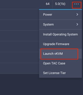
Step 5. Follow the prompts to ignore certificate workings (if any) and launch the HTML5 KVM console.
Step 6. Repeat steps 1 - 5 to launch the HTML5 KVM console for all the servers.
Procedure 3. Set Up VMware ESXi Installation on each ESXi Host
Step 1. In the KVM window, click Virtual Media > vKVM-Mapped vDVD.
Step 2. Browse and select the ESXi installer ISO image file downloaded in the last step.
Step 3. Click Map Drive.
Step 4. Select Macros > Static Macros > Ctrl + Alt + Delete to reboot the Server if the server is showing shell prompt. If the server is shutdown, from Intersight, select “…” next to server and click Power On.
Step 5. Monitor the server boot process in the KVM. Server should find the boot LUNs and begin to load the ESXi installer.
Note: If the ESXi installer fails to load because the software certificates cannot be validated, reset the server, and when prompted, press F2 to go into BIOS and set the system time and date to current. The ESXi installer should load properly.
Procedure 4. Install VMware ESXi
Step 1. After the ESXi installer is finished loading (from the last step), press Enter to continue with the installation.
Step 2. Read and accept the end-user license agreement (EULA). Press F11 to accept and continue.
Note: It may be necessary to map function keys as User Defined Macros under the Macros menu in the KVM console.
Step 3. Select the NetApp boot LUN that was previously set up as the installation disk for ESXi and press Enter to continue with the installation.
Step 4. Select the appropriate keyboard layout and press Enter.
Step 5. Enter and confirm the root password and press Enter.
Step 6. The installer issues a warning that the selected disk will be repartitioned. Press F11 to continue with the installation.
Step 7. After the installation is complete, click Virtual Media to unmap the installer ISO. Press Enter to reboot the server.
Procedure 5. Set Up Management Networking for ESXi Hosts
Note: Adding a management network for each VMware host is required for managing the host.
Step 1. After the server has finished rebooting, in the UCS KVM console, press F2 to customize VMware ESXi.
Step 2. Log in as root, enter the password set during installation, and press Enter to log in.
Step 3. Use the down arrow key to select Troubleshooting Options and press Enter.
Step 4. Select Enable SSH and press Enter.
Step 5. Press Esc to exit the Troubleshooting Options menu.
Step 6. Select the Configure Management Network option and press Enter.
Step 7. Select Network Adapters and press Enter.
Step 8. Using the spacebar, select vmnic1 in addition to the pre-selected vmnic0.
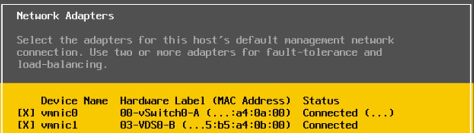
Step 9. Press Enter.
Step 10. Under VLAN (optional) enter the IB-MGMT VLAN and press Enter.
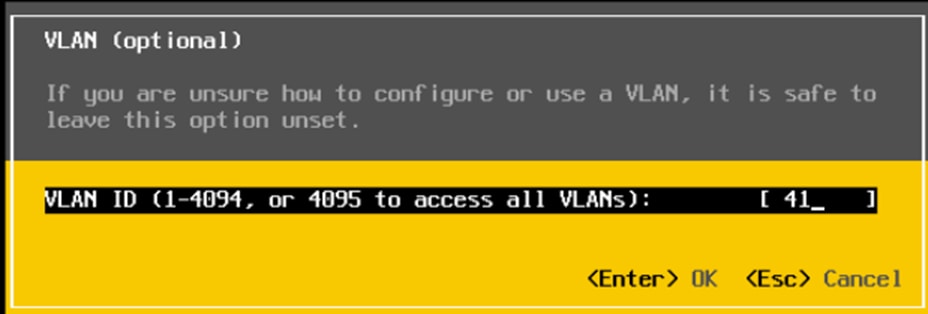
Step 11. Select IPv4 Configuration and press Enter.
Note: When using DHCP to set the ESXi host networking configuration, setting up a manual IP address is not required.
Step 12. Select the Set static IPv4 address and network configuration option by using the arrow keys and space bar.
Step 13. Under IPv4 Address, enter the IP address for managing the ESXi host.
Step 14. Under Subnet Mask, enter the subnet mask.
Step 15. Under Default Gateway, enter the default gateway.
Step 16. Press Enter to accept the changes to the IP configuration.
Step 17. Select the IPv6 Configuration option and press Enter.
Step 18. Using the spacebar, select Disable IPv6 (restart required) and press Enter.
Step 19. Select the DNS Configuration option and press Enter.
Note: If the IP address is configured manually, the DNS information must be provided.
Step 20. Using the spacebar, select the option Use the following DNS server addresses and hostname:
a. Under Primary DNS Server, enter the IP address of the primary DNS server.
b. Optional: Under Alternate DNS Server, enter the IP address of the secondary DNS server.
c. Under Hostname, enter the fully qualified domain name (FQDN) for the ESXi host.
d. Press Enter to accept the changes to the DNS configuration.
e. Press Esc to exit the Configure Management Network submenu.
f. Press Y to confirm the changes and reboot the ESXi host.
Procedure 6. Configure FlexPod VMware ESXi Ansible Hosts
Step 1. Edit the following variable files to ensure proper VMware specific variables are entered:
● FlexPod-for-EHR/Ansible/inventory
● FlexPod-for-EHR/Ansible/group_vars/all.yml
● FlexPod-for-EHR/Ansible/roles/ESXIhosts/defaults/main.yml
Step 2. From /root/ FlexPod-for-EHR/Ansible, run the Setup_ESXi.yml Ansible playbook:
ansible-playbook ./Setup_ESXi.yml -i inventory
FlexPod VMware ESXi Manual Configuration
Although the VMware ESXi Ansible configuration configures all three ESXi hosts, the manual configuration, after the installation of necessary drivers, configures only the first host using the ESXi web interface then adds the second and third hosts after vCenter is installed.
Procedure 1. Install Cisco VIC Drivers and NetApp NFS Plug-in for VAAI
Step 1. Download the offline bundle for the Cisco VIC nfnic driver and the NetApp NFS Plug-in for VMware VAAI to the Management workstation:
● Download the ISO Image of Cisco UCS related VMware drivers only from: https://software.cisco.com/download/home/286329080/type/283853158/release/5.0(1a).
● Mount ISO image and extract file Cisco-nfnic_5.0.0.15-1OEM.700.1.0.15843807_18697950.zip.
● Follow Storage > Cisco > VIC > ESXi_7.0U2 > nfnic_5.0.0.15 and copy the Cisco-nfnic_5.0.0.15-1OEM.700.1.0.15843807_18697950.zip file.
● NetApp NFS Plug-in for VMware VAAI 2.0 (NetAppNasPluginV2.0.zip) from https://mysupport.netapp.com/site/products/all/details/nfsplugin-vmware-vaai/downloads-tab/download/61278/2.0.
Note: Cisco VIC nenic version 1.0.4.0 is already included in the Cisco Custom ISO for VMware vSphere version 7.0.2.
Note: Consult the Cisco UCS Hardware Compatibility List and the NetApp Interoperability Matrix Tool to determine latest supported combinations of firmware and software.
Step 2. Install VMware VIC Drivers and the NetApp NFS Plug-in for VMware VAAI on the ESXi hosts:
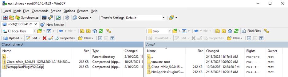
Step 3. Using an SCP program, copy the two bundles referenced above to the /tmp directory on each ESXi host.
Step 4. SSH to each VMware ESXi host and log in as root.
Step 5. Run the following commands on each host:
esxcli software component apply -d /tmp/Cisco-nfnic_5.0.0.15-1OEM.700.1.0.15843807_18697950.zip
esxcli software vib install -d /tmp/NetAppNasPluginV2.0.zip
reboot
Step 6. After reboot, SSH back into each host and use the following commands to ensure the correct version are installed:
esxcli software component list | grep nfnic
esxcli software vib list | grep NetApp
Procedure 2. Configure FlexPod VMware ESXi for First ESXi Host
Note: In this procedure, you’re only setting up the first ESXi host. The remaining hosts will be added to vCenter and setup from the vCenter.
Step 1. Log into the first ESXi host using the VMware Host Client.
Step 2. Open a web browser and navigate to the first ESXi server’s management IP address.
Step 3. Enter root as the User name.
Step 4. Enter the <root password>.
Step 5. Click Log in to connect.
Step 6. Decide whether to join the VMware Customer Experience Improvement Program or not and click OK.
Procedure 3. Set Up VMkernel Ports and Virtual Switch on the First ESXi Host
Step 1. From the Host Client Navigator, select Networking.
Step 2. In the center pane, select the Virtual switches tab.
Step 3. Highlight the vSwitch0 line.
Step 4. Click Edit settings.
Step 5. Change the MTU to 9000.
Step 6. Expand Link Discovery
Step 7. Set Mode to Both
Step 8. Expand NIC teaming.
Step 9. In the Failover order section, select vmnic1 and click Mark active.
Step 10. Verify that vmnic1 now has a status of Active.
Step 11. Click Save.
Step 12. Select Networking, then select the Port groups tab.
Step 13. In the center pane, right-click VM Network and select Edit settings.
Step 14. Name the port group IB_MGMT. Set the VLAN ID to <IB-MGMT-VLAN> (for example, 41).
Note: (Optional) The IB-MGMT VLAN can be set as the native VLAN for the vSwitch0 vNIC templates and the port group’s VLAN ID can be set to 0.
Step 15. Click Save to finalize the edits for the IB-MGMT Network port group.
Step 16. At the top, select the VMkernel NICs tab.
Step 17. Click Add VMkernel NIC.
Step 18. For New port group, enter VMkernel-Infra-NFS.
Step 19. For Virtual switch, select vSwitch0.
Step 20. Enter <infra-nfs-vlan-id> (for example, 42) for the VLAN ID.
Step 21. Change the MTU to 9000.
Step 22. Select Static IPv4 settings and expand IPv4 settings.
Step 23. Enter the NFS IP address and netmask.
Step 24. Leave TCP/IP stack set at Default TCP/IP stack and do not choose any of the Services.
Step 25. Click Create.
Step 26. Select the Virtual Switches tab, then vSwitch0. The properties for vSwitch0 should be similar to the following screenshot:
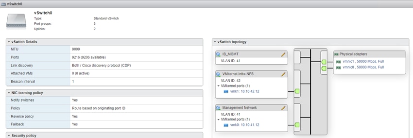
Procedure 4. Mount Datastores on the First ESXi Host
Step 1. From the Web Navigator, click Storage.
Step 2. In the center pane, click the Datastores tab.
Step 3. In the center pane, select New Datastore to add a new datastore.
Step 4. In the New datastore popup, select Mount NFS datastore and click Next.
Step 5. Enter infra_datastore_01 for the datastore name and IP address of NetApp nfs-lif-01 LIF for the NFS server. Enter /infra_datastore_01 for the NFS share. Select the NFS version. Click Next.
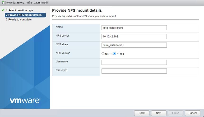
Step 6. Review information and click Finish.
Step 7. The datastore should now appear in the datastore list.
Step 8. In the center pane, select New Datastore to add a new datastore.
Step 9. In the New datastore popup, select Mount NFS datastore and click Next.
Step 10. Enter infra_swap for the datastore name and IP address of NetApp nfs-lif-01 LIF for the NFS server. Enter /infra_swap for the NFS share. Select the NFS version. Click Next.
Step 11. Click Finish. The datastore should now appear in the datastore list.
Procedure 5. Configure NTP Server on the First ESXi Host
Step 1. From the Web Navigator, click Manage.
Step 2. In the center pane, click System > Time & date.
Step 3. Click Edit NTP Settings.
Step 4. Select Use Network Time Protocol (enable NTP client).
Step 5. Use the drop-down list to select Start and stop with host.
Step 6. Enter the NTP server IP address(es) in the NTP servers.
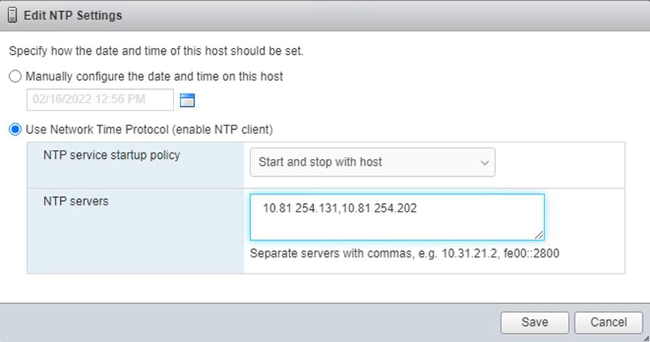
Step 7. Click Save to save the configuration changes.
Step 8. Select the Services tab.
Step 9. Right-click ntpd and click Start.
Step 10. System > Time & date should now show “Running” for the NTP service status.
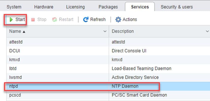
Procedure 6. Configure ESXi Host Swap on the First ESXi Host
Step 1. From the Web Navigator, click Manage.
Step 2. In the center pane, click System > Swap.
Step 3. Click Edit settings.
Step 4. Use the drop-down list to select infra_swap. Leave all other settings unchanged.
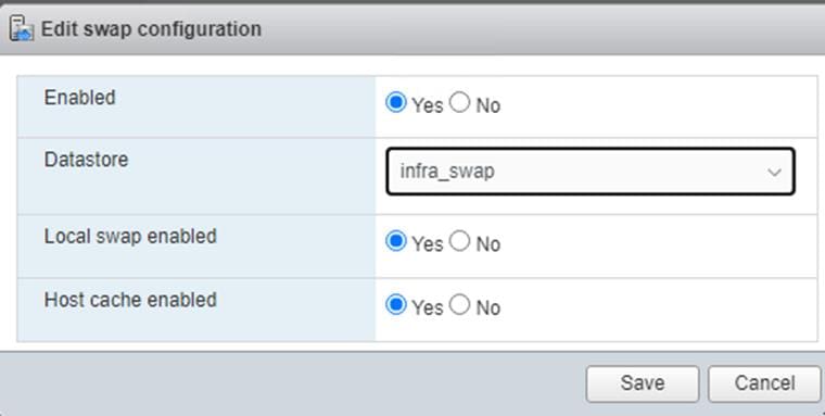
Step 5. Click Save to save the configuration changes.
Procedure 7. Configure Host Power Policy on the First ESXi Host
Note: Implementation of this policy is recommended in Performance Tuning Guide for Cisco UCS M6 Servers: for maximum VMware ESXi performance. This policy can be adjusted based on customer requirements.
Step 1. From the Web Navigator, click Manage.
Step 2. In the center pane, click Hardware > Power Management.
Step 3. Click Change policy.
Step 4. Select High performance and click OK.
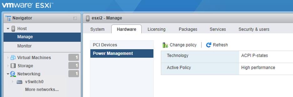
The procedures in the following subsections provide detailed instructions for installing the VMware vCenter 7.0U3c Server Appliance in a FlexPod environment.
Procedure 1. Download vCenter 7.0U3c from VMware
Step 1. Click the following link: https://customerconnect.vmware.com/downloads/details?downloadGroup=VC70U3C&productId=974&rPId=78220and download the VMware-VCSA-all-7.0.3-19234570.iso.
Step 2. You will need a VMware user id and password on vmware.com to download this software.
Procedure 2. Install the VMware vCenter Server Appliance
Note: The VCSA deployment consists of 2 stages: installation and configuration.
Step 1. Locate and copy the VMware-VCSA-all-7.0.3-19234570.iso file to the desktop of the management workstation. This ISO is for the VMware vSphere 7.0U3c vCenter Server Appliance.
Step 2. Mount the ISO image as a disk on the management workstation. (For example, with the Mount command in Windows Server 2012 and above).
Step 3. In the mounted disk directory, navigate to the vcsa-ui-installer > win32 directory and double-click installer.exe. The vCenter Server Appliance Installer wizard appears.
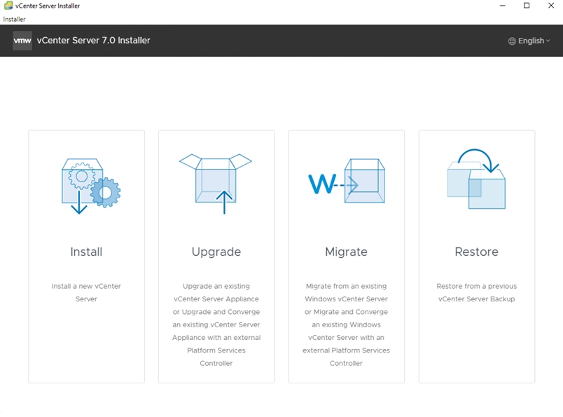
Step 4. Click Install to start the vCenter Server Appliance deployment wizard.
Step 5. Click NEXT in the Introduction section.
Step 6. Read and accept the license agreement and click NEXT.
Step 7. In the “vCenter Server deployment target” window, enter the FQDN or IP address of the destination host, User name (root) and Password. Click NEXT.
Note: Installation of vCenter on a separate existing management infrastructure is recommended. If a separate management infrastructure is not available, customers can choose the recently configured first ESXi host as an installation target.
Step 8. Click YES to accept the certificate.
Step 9. Enter the Appliance VM name and password details shown in the “Set up vCenter Server VM” section. Click NEXT.
Step 10. In the “Select deployment size” section, select the Deployment size and Storage size. For example, select “Small” and “Default.” Click NEXT.
Step 11. Select the datastore (for example, infra_datastore_02) for storage. Click NEXT.
Step 12. In the Network Settings section, configure the following settings:
a. Select a Network: IB-MGMT Network
Note: It is important that the vCenter VM stay on the IB-MGMT Network on vSwitch0 and not moved to a vDS. If vCenter is moved to a vDS and the virtual environment is completely shut down and then brought back up, trying to bring up vCenter on a different host than the one it was running on before the shutdown, will cause problems with the network connectivity. With the vDS, for a virtual machine to move from one host to another, vCenter must be up and running to coordinate the move of the virtual ports on the vDS. If vCenter is down, the port move on the vDS cannot occur correctly. Moving vCenter to a different host on vSwitch0 does not require vCenter to already be up and running.
b. IP version: IPV4
c. IP assignment: static
d. FQDN: <vcenter-fqdn>
e. IP address: <vcenter-ip>
f. Subnet mask or prefix length: <vcenter-subnet-mask>
g. Default gateway: <vcenter-gateway>
h. DNS Servers: <dns-server1>,<dns-server2>
Step 13. Click NEXT.
Step 14. Review all values and click FINISH to complete the installation.
Note: The vCenter Server appliance installation will take a few minutes to complete.
Step 15. When Stage 1, Deploy vCenter Server, is complete, click CONTINUE to proceed with stage 2.
Step 16. Click NEXT.
Step 17. In the vCenter Server configuration window, configure these settings:
a. Time Synchronization Mode: Synchronize time with NTP servers.
b. NTP Servers: NTP server IP addresses.
c. SSH access: Enabled.
Step 18. Click NEXT.
Step 19. Complete the SSO configuration as shown below (or according to your organization’s security policies):
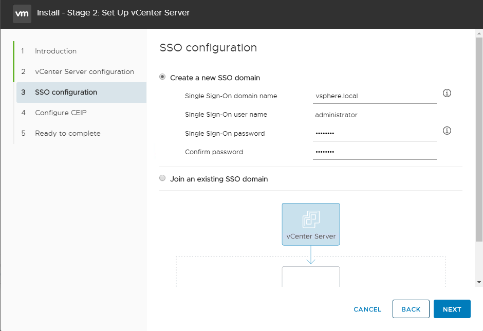
If a vCenter deployment size of Small or larger was selected in the vCenter setup, it is possible that the VCSA’s CPU setup does not match the Cisco UCS server CPU hardware configuration. Cisco UCS X210c M6 and B200 M6 servers are 2-socket servers. During this validation, the Small deployment size was selected and vCenter was setup for a 4-socket server. This setup can cause issues in the VMware ESXi cluster Admission Control.
Procedure 1. Resolve vCenter CPU Settings
Step 1. Open a web browser on the management workstation and navigate to vCenter or ESXi server where vCenter appliance was deployed and login.
Step 2. Click the vCenter VM, right-click and select Edit settings.
Step 3. In the Edit settings window, expand CPU and check the value of Sockets.
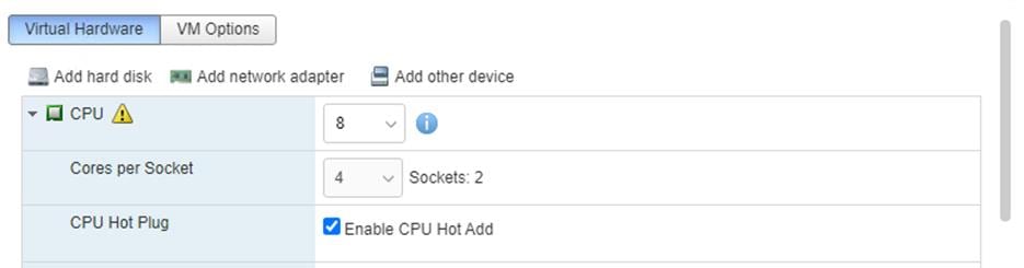
Step 4. If the number of Sockets match the server configuration, click Cancel.
Step 5. If the number of Sockets does not match the server configuration, it will need to be adjusted:
a. Right-click the vCenter VM and click Guest OS > Shut down. Click Yes on the confirmation.
b. When vCenter is shut down, right-click the vCenter VM and select Edit settings.
c. In the Edit settings window, expand CPU and change the Cores per Socket value to make the Sockets value equal to the server configuration.
Step 6. Click Save.
Step 7. Right-click the vCenter VM and click Power > Power on. Wait approximately 10 minutes for vCenter to come up.
Procedure 2. Setup VMware vCenter Server
Step 1. Using a web browser, navigate to https://<vcenter-ip-address>:5480. Navigate security screens.
Step 2. Log into the VMware vCenter Server Management interface as root with the root password set in the vCenter installation.
Step 3. In the menu on the left, click Time.
Step 4. Click EDIT to the right of Time zone.
Step 5. Select the appropriate Time zone and click SAVE.
Step 6. In the menu on the left select Administration.
Step 7. According to your Security Policy, adjust the settings for the root user and password.
Step 8. In the menu on the left click Update.
Step 9. Follow the prompts to stage and install any available vCenter updates.
Step 10. In the upper right-hand corner of the screen, click root > Logout to logout of the Appliance Management interface.
Step 11. Using a web browser, navigate to https://<vcenter-ip-address> and navigate through security screens.
Note: With VMware vCenter 7.0 and above, the use of the vCenter FQDN is required.
Step 12. Click LAUNCH VSPHERE CLIENT (HTML5).
Note: The VMware vSphere HTML5 Client is the only option in vSphere 7. All the old clients have been deprecated.
Step 13. Log in using the Single Sign-On username (administrator@vsphere.local) and password created during the vCenter installation. Dismiss the Licensing warning.
Procedure 3. Add AD User Authentication to vCenter (Optional)
Step 1. In the AD Infrastructure, using the Active Directory Users and Computers tool, setup a Domain Administrator user with a user name such as flexadmin (FlexPod Admin).
Step 2. Connect to https://<vcenter-ip> and select LAUNCH VSPHERE CLIENT (HTML5).
Step 3. Log in as Administrator@vsphere.local (or the SSO user set up in vCenter installation) with the corresponding password.
Step 4. Under Menu, click Administration. In the list on the left, under Single Sign On, click Configuration.
Step 5. In the center pane, under Configuration, click the Identity Provider tab.
Step 6. In the list under Type, select Active Directory Domain.
Step 7. Click JOIN AD.
Step 8. Fill in the AD domain name, the Administrator user, and the domain Administrator password. Do not fill in an Organizational unit. Click JOIN.
Step 9. Click Acknowledge.
Step 10. In the list on the left under Deployment, select System Configuration. Click the radio button to select the vCenter, then click REBOOT NODE.
Step 11. Input a reboot reason and click REBOOT. The reboot will take approximately 10 minutes for full vCenter initialization.
Step 12. Log back into the vCenter vSphere HTML5 Client as Administrator@vsphere.local.
Step 13. Under Menu, click Administration. In the list on the left, under Single Sign On, click Configuration.
Step 14. In the center pane, under Configuration, click the Identity Provider tab. Under Type, select Identity Sources. Click ADD.
Step 15. Make sure Active Directory (Integrated Windows Authentication) is selected, your Windows Domain name is listed, and Use machine account is selected. Click ADD.
Step 16. In the list select the Active Directory (Integrated Windows Authentication) Identity source type. If desired, select SET AS DEFAULT and click OK.
Step 17. On the left under Access Control, select Global Permissions.
Step 18. In the center pane, click the + sign to add a Global Permission.
Step 19. In the Add Permission window, select your AD domain for the Domain.
Step 20. On the User/Group line, enter either the FlexPod Admin username or the Domain Admins group. Leave the Role set to Administrator. Check the box for Propagate to children.
Note: The FlexPod Admin user was created in the Domain Admins group. The selection here depends on whether the FlexPod Admin user will be the only user used in this FlexPod If additional users will be added later. By selecting the Domain Admins group, any user placed in that AD Domain group will be able to login to vCenter as an Administrator.
Step 21. Click OK to add the selected User or Group. The user or group should now appear in the Global Permissions list with the Administrator role.
Step 22. Log out and log back into the vCenter HTML5 Client as the FlexPod Admin user. You will need to add the domain name to the user, for example, flexadmin@domain.
Procedure 4. vCenter - Initial Configuration
Step 1. In the center pane, click ACTIONS > New Datacenter.
Step 2. Type Epic-DC in the Datacenter name field.
Step 3. Click OK.
Step 4. Expand the vCenter.
Step 5. Right-click the datacenter Epic-DC in the list in the left pane. Click New Cluster…
Step 6. Provide a name for the cluster (for example, Epic-Cluster).
Step 7. Turn on DRS and vSphere HA. Do not turn on vSAN.
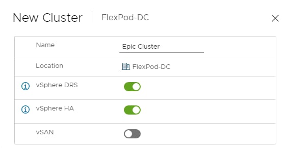
Step 8. Click NEXT and then click FINISH to create the new cluster.
Step 9. Right-click the cluster and click Settings.
Step 10. Click Configuration > General in the list located and click EDIT.
Step 11. Click Datastore specified by host for the Swap file location and click OK.
Step 12. Right-click the cluster and select Add Hosts.
Step 13. In the IP address or FQDN field, enter either the IP address or the FQDN of the first VMware ESXi host. Enter root as the Username and the root password. Click NEXT.
Step 14. In the Security Alert window, select the host and click OK.
Step 15. Verify the Host summary information and click NEXT.
Step 16. Ignore warnings about the host being moved to Maintenance Mode and click FINISH to complete adding the host to the cluster.
Note: The added ESXi host will have Warnings that the ESXi Shell and SSH have been enabled. These warnings can be suppressed. The host will also have a TPM Encryption Key Recovery alert that can be reset to green.
Step 17. In the center pane under Storage, click Storage Devices. Make sure the NETAPP Fibre Channel Disk LUN 0 is selected.
Step 18. Click the Paths tab.
Step 19. Ensure that 4 paths appear, two of which should have the status Active (I/O). The output below shows the paths for the boot LUN.
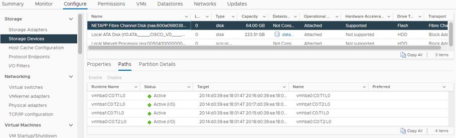
Add and Configure VMware ESXi Hosts in vCenter
Procedure 1. Add the ESXi Hosts to vCenter
Step 1. From the Home screen in the VMware vCenter HTML5 Interface, click Menu > Hosts and Clusters.
Step 2. Right-click the cluster and click Add Hosts.
Step 3. In the IP address or FQDN field, enter either the IP address or the FQDN name of the configured VMware ESXi host. Also enter the user id (root) and associated password. If more than one host is being added, add the corresponding host information, optionally selecting “Use the same credentials for all hosts.” Click NEXT.
Step 4. Select all hosts being added and click OK to accept the thumbprint(s).
Step 5. Review the host details and click NEXT to continue.
Step 6. Review the configuration parameters and click FINISH to add the host(s).
Note: The added ESXi host(s) will be placed in Maintenance Mode and will have Warnings that the ESXi Shell and SSH have been enabled. These warnings can be suppressed. The TPM Encryption Recovery Key Backup Alarm can also be Reset to Green.
Procedure 2. Set Up VMkernel Ports and Virtual Switch
Step 1. In the vCenter HTML5 Interface, under Hosts and Clusters select the ESXi host.
Step 2. In the center pane, click the Configure tab.
Step 3. In the list, select Virtual switches under Networking.
Step 4. Expand Standard Switch: vSwitch0.
Step 5. Select EDIT to Edit settings.
Step 6. Change the MTU to 9000.
Step 7. Select Teaming and failover located on the left.
Step 8. In the Failover order section, use the arrow icons to move the vmnics until both are Active adapters.
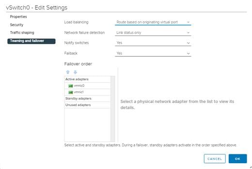
Step 9. Click OK.
Step 10. In the center pane, to the right of VM Network click “…” > Remove to remove the port group. Click YES on the confirmation.
Step 11. Click ADD NETWORKING to add a new VM port group.
Step 12. Select Virtual Machine Port Group for a Standard Switch and click NEXT.
Step 13. Ensure vSwitch0 is shown for Select an existing standard switch and click NEXT.
Step 14. Name the port group “IB_MGMT” and set the VLAN to IB-MGMT-VLAN (for example, 41). Click NEXT.
Note: (Optional) The IB-MGMT VLAN can be set as the native VLAN for the vSwitch0 vNIC templates on Cisco Intersight. The port group’s VLAN ID can then be set to 0.
Step 15. Click FINISH to complete adding the IB_MGMT VM port group.
Step 16. Under Networking, click VMkernel adapters.
Step 17. In the center pane, click Add Networking.
Step 18. Make sure VMkernel Network Adapter is selected and click NEXT.
Step 19. Select an existing standard switch and click BROWSE. Select vSwitch0 and click OK. Click NEXT.
Step 20. For Network label, enter VMkernel-Infra-NFS.
Step 21. Enter <infra-nfs-vlan-id for example, 42> for the VLAN ID.
Step 22. Select Custom for MTU and set the value to 9000.
Step 23. Leave the Default TCP/IP stack selected and do not select any of the Enabled services. Click NEXT.
Step 24. Select Use static IPv4 settings and enter the IPv4 address and subnet mask for the Infra-NFS VMkernel port for this ESXi host.
Step 25. Click NEXT.
Step 26. Review the settings and click FINISH to create the VMkernel port.
Step 27. To verify the vSwitch0 setting, under Networking, select Virtual switches, then expand vSwitch0. The properties for vSwitch0 should be similar to:
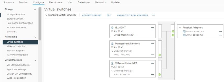
Step 28. Repeat steps 1 – 27 for all the ESXi hosts being added.
Procedure 3. Mount Required Datastores
Step 1. From the vCenter Home screen, click Menu > Storage.
Step 2. Expand Epic-DC.
Step 3. Right-click infra_datastore_01 and select Mount Datastore to Additional Hosts.
Step 4. Select all the ESXi host(s) and click OK.
Step 5. Repeat steps 1 – 4 to mount the infra_datastore_2 and infra_swap datastores on all the ESXi host(s).
Step 6. Select infra_datastore_01 and in the center pane, click Hosts. Verify that all the ESXi host(s) are listed. Repeat this process to verify that both infra_datastore_2 and infra_swap datastores are also mounted on all hosts.
Procedure 4. Configure NTP on ESXi Host
Step 1. In the vCenter HTML5 Interface, under Hosts and Clusters select the ESXi host.
Step 2. In the center pane, select the Configure tab.
Step 3. In the list under System, click Time Configuration.
Step 4. Click EDIT next to Network Time Protocol.
Step 5. Check the box for Enable.
Step 6. Enter the NTP Server IP address(es) in the NTP servers box separated by a comma.
Step 7. Check the box for Start NTP Service.
Step 8. Use the drop-down list to select Start and stop with host.
Step 9. Click OK to save the configuration changes.
Step 10. Verify that NTP service is now enabled and running, and the clock is now set to correct time.
Step 11. Repeat steps 1 – 10 for all the ESXi hosts.
Procedure 5. Change ESXi Power Management Policy
Note: Implementation of this policy is recommended in Performance Tuning Guide for Cisco UCS M6 Servers: https://www.cisco.com/c/en/us/products/collateral/servers-unified-computing/ucs-b-series-blade-servers/performance-tuning-guide-ucs-m6-servers.html for maximum VMware ESXi performance. This policy can be adjusted based on customer requirements.
Step 1. In the vCenter HTML5 Interface, under Hosts and Clusters select the ESXi host.
Step 2. In the center pane, click the Configure tab.
Step 3. Under Hardware, click Overview. Scroll to the bottom and next to Power Management, click EDIT POWER POLICY.
Step 4. Select High performance and click OK.
FlexPod VMware vSphere Distributed Switch (vDS)
This section provides detailed procedures for setting up VMware vDS in vCenter. Based on the VLAN configuration in Intersight, a vMotion, and a VM-Traffic port group will be added to the vDS. Any additional VLAN-based port groups added to the vDS would require changes in Intersight and the Cisco Nexus 9K switches.
In this document, the infrastructure ESXi management VMkernel ports, the In-Band management interfaces including the vCenter management interface, and the infrastructure NFS VMkernel ports are left on vSwitch0 to facilitate bringing the virtual environment back up in the event it needs to be completely shut down. The vMotion VMkernel ports are moved to the vDS to allow for future QoS support. The vMotion port group is also pinned to Cisco UCS fabric B and pinning configuration in vDS ensures consistency across all ESXi hosts.
Procedure 1. Configure the VMware vDS in vCenter
Step 1. After logging into the VMware vSphere HTML5 Client, click Networking under Menu.
Step 2. Right-click the Epic-DC datacenter and click Distributed Switch > New Distributed Switch.
Step 3. Give the Distributed Switch a descriptive name (for example, Epic_vDS) and click NEXT.
Step 4. Make sure version 7.0.0 – ESXi 7.0.0 and later is selected and click NEXT.
Step 5. Change the Number of uplinks to 2. If VMware Network I/O Control is to be used for Quality of Service, leave Network I/O Control Enabled. Otherwise, Disable Network I/O Control. Enter VM-Traffic for the Port group name. Click NEXT.
Step 6. Review the information and click FINISH to complete creating the vDS.
Step 7. Expand the Epic-DC datacenter and the newly created vDS. Click the newly created vDS.
Step 8. Right-click the VM-Traffic port group and click Edit Settings.
Step 9. Click VLAN.
Step 10. Click VLAN for VLAN type and enter the <VM-Traffic> VLAN ID (for example, 44). Click OK.
Step 11. Right-click the vDS and click Settings > Edit Settings.
Step 12. In the Edit Settings window, click the Advanced tab.
Step 13. Change the MTU to 9000. The Discovery Protocol can optionally be changed to Link Layer Discovery Protocol and the Operation to Both. Click OK.
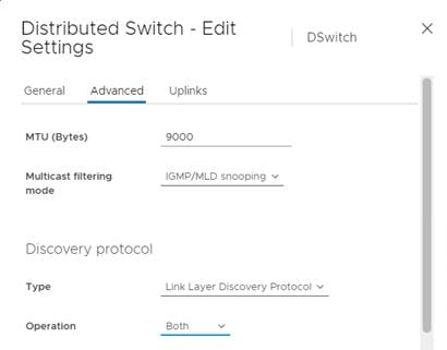
Step 14. To create the vMotion port group, right-click the vDS, select Distributed Port Group > New Distributed Port Group.
Step 15. Enter VMKernel-vMotion as the name and click NEXT.
Step 16. Set the VLAN type to VLAN, enter the VLAN ID used for vMotion (for example, 43), check the box for Customize default policies configuration, and click NEXT.
Step 17. Leave the Security options set to Reject and click NEXT.
Step 18. Leave the Ingress and Egress traffic shaping options as Disabled and click NEXT.
Step 19. Select Uplink 1 from the list of Active uplinks and click MOVE DOWN twice to place Uplink 1 in the list of Standby uplinks. This will pin all vMotion traffic to UCS Fabric Interconnect B except when a failure occurs.
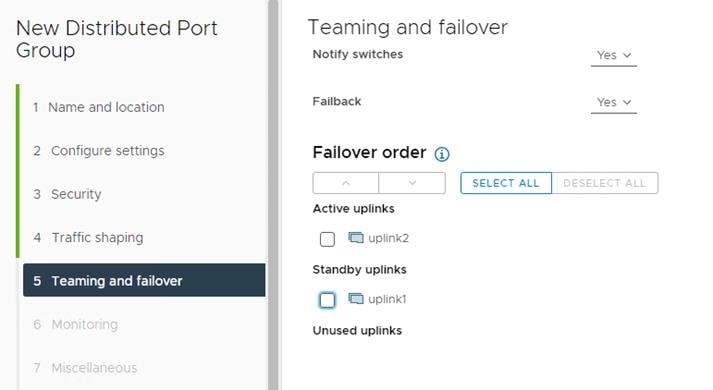
Step 20. Click NEXT.
Step 21. Leave NetFlow disabled and click NEXT.
Step 22. Leave Block all ports set as No and click NEXT.
Step 23. Confirm the options and click FINISH to create the port group.
Step 24. Right-click the vDS and click Add and Manage Hosts.
Step 25. Make sure Add hosts is selected and click NEXT.
Step 26. Click the green + sign to add new hosts. Select the first ESXi host and click OK. Click NEXT.
Step 27. Select vmnic2 and click Assign uplink. Choose Uplink 1 and click OK.
Step 28. Select vmnic3 and click Assign uplink. Select Uplink 2 and click OK.
Note: It is important to assign the uplinks as shown below. This allows the port groups to be pinned to the appropriate Cisco UCS fabric.
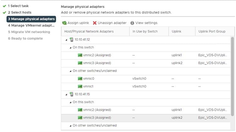
Step 29. Click NEXT.
Step 30. Do not migrate any VMkernel ports and click NEXT.
Step 31. Do not migrate any virtual machine networking ports. Click NEXT.
Step 32. Click FINISH to complete adding the ESXi host to the vDS.
Step 33. Select Hosts and Clusters under Menu and select the first ESXi host. In the center pane, select the Configure tab.
Step 34. In the list under Networking, select VMkernel adapters.
Step 35. Select ADD NETWORKING.
Step 36. In the Add Networking window, ensure that VMkernel Network Adapter is selected and click NEXT.
Step 37. Ensure that Select an existing network is selected and click BROWSE.
Step 38. Select VMKernel-vMotion and click OK.
Step 39. Click NEXT.
Step 40. From the MTU drop-down list, select Custom and ensure the MTU is set to 9000.
Step 41. From the TCP/IP stack drop-down list, select vMotion. Click NEXT.
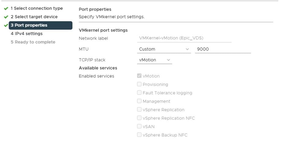
Step 42. Select Use static IPv4 settings and fill in the IPv4 address and Subnet mask for the first ESXi host’s vMotion IP address. Click NEXT.
Step 43. Review the information and click FINISH to complete adding the vMotion VMkernel port.
Procedure 2. Add the ESXi Host(s) to the VMware Virtual Distributed Switch
Step 1. From the VMware vSphere HTML5 Client, click Networking under Menu.
Step 2. Right-click the vDS and select Add and Manage Hosts.
Step 3. Ensure that Add hosts is selected and click NEXT.
Step 4. Click the green + sign to add New hosts. Select the ESXi host(s) and click OK. Click NEXT.
Step 5. Select vmnic2 on each host and click Assign uplink. Select Uplink 1 and click OK.
Step 6. Select vmnic3 on each host and click Assign uplink. Select Uplink 2 and click OK.
Step 7. If more than one host is being connected to the vDS, check the box for Apply this uplink assignment to the rest of the hosts.
Note: It is important to assign the uplinks as defined in these steps. This allows the port groups to be pinned to the appropriate Cisco UCS fabric.
Step 8. Click NEXT.
Step 9. Do not migrate any VMkernel ports and click NEXT.
Step 10. Do not migrate any VM ports and click NEXT.
Step 11. Click FINISH to complete adding the ESXi host(s) to the vDS.
Procedure 3. Add the vMotion VMkernel Port(s) to the ESXi Host
Step 1. In the vCenter HTML5 Interface, under Hosts and Clusters select the ESXi host.
Step 2. Click the Configure tab.
Step 3. In the list under Networking, click VMkernel adapters.
Step 4. Select Add Networking to add host networking.
Step 5. Make sure VMkernel Network Adapter is selected and click NEXT.
Step 6. Select BROWSE to the right of Select an existing network.
Step 7. Select VMKernel-vMotion on the vDS and click OK.
Step 8. Click NEXT.
Step 9. Make sure the Network label is VMkernel-vMotion with the vDS in parenthesis. From the drop-down list, select Custom for MTU and make sure the MTU is set to 9000. Select the vMotion TCP/IP stack and click NEXT.
Step 10. Select Use static IPv4 settings and input the host’s vMotion IPv4 address and Subnet mask.
Step 11. Click NEXT.
Step 12. Review the parameters and click FINISH to add the vMotion VMkernel port.
Finalize the vCenter and ESXi Setup
This section details how to finalize the VMware installation.
Procedure 1. Configure ESXi Host Swap
Step 1. In the vCenter HTML5 Interface, under Hosts and Clusters select the ESXi host.
Step 2. In the center pane, click the Configure tab.
Step 3. In the list under System, click System Swap.
Step 4. In the right pane, click EDIT.
Step 5. Select Can use datastore and use the drop-down list to select infra_swap. Leave all other settings unchanged.
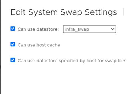
Step 6. Click OK to save the configuration changes.
Procedure 2. Configure Virtual Machine Swap File Location
Step 1. In Virtual Center, click on the Cluster name, and select the Configure menu.
Step 2. Select the General option.
Step 3. In the window on the right, click EDIT above the Datastore specified by host.
Step 4. Select Datastore specified by host option.
Step 5. Click OK.
Step 6. For each server in the cluster, click on Configuration, then under Virtual Machines, select Swap File Location.
Step 7. On the right, click EDIT.
Step 8. Double-click the infra_swap datastore to select it.
Step 9. Click OK.
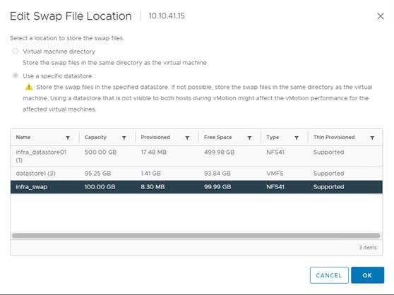
Procedure 3. Verify ESXi Host Fibre Channel Multi-Path Configuration
Step 1. In the vCenter HTML5 Interface, under Hosts and Clusters select the ESXi host.
Step 2. In the center pane, click the Configure tab.
Step 3. In the list under Storage, click Storage Devices. Make sure the NETAPP Fibre Channel Disk is selected.
Step 4. Select the Paths tab.
Step 5. Ensure that 4 FC paths appear, two of which should have the status Active (I/O).
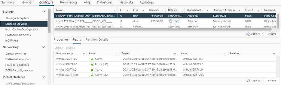
Procedure 4. VMware ESXi 7.0 U3 TPM Attestation
Note: If your Cisco UCS servers have Trusted Platform Module (TPM) 2.0 modules installed, the TPM can provide assurance that ESXi has booted with UEFI Secure Boot enabled and using only digitally signed code. In the Create a Cisco UCS Server Profile section of this document, UEFI secure boot was enabled in the boot policy. A server can boot with UEFI Secure Boot with or without a TPM 2.0 module. If it has a TPM, VMware vCenter can attest that the server booted with UEFI Secure Boot.
Step 1. For Cisco UCS servers that have TPM 2.0 modules installed, TPM Attestation can be verified in the vSphere HTML5 Client.
Step 2. In the vCenter HTML5 Interface, under Hosts and Clusters select the cluster.
Step 3. In the center pane, click the Monitor tab.
Step 4. Click Monitor > Security. The Attestation status will show the status of the TPM.
Storage Configuration – ONTAP NVMe Namespace Mapping and Finalizing ONTAP Storage
Procedure 1. Ansible Configuration
Step 1. Edit the following variable file and update the “namespaces” and “subsystem” variables under nvme_specs:
FlexPod-for-EHR/Ansible/vars/ontap_main.yml
Note: Add the NQNs from each host to the subsystem variable. The NVME namespace will be shared by all the hosts in the nvme subsystem.
Step 2. From /root/ FlexPod-for-EHR/Ansible, invoke the ansible scripts for this section use the following command:
ansible-playbook -i inventory Setup_ONTAP.yml -t ontap_config_part_3
Note: Use the -vvv tag to see detailed execution output log.
Procedure 2. Manual Configuration
Step 1. Create NVMe namespace:
vserver nvme namespace create -vserver SVM_name -path path -size size_of_namespace -ostype OS_type
AA17-A400::> vserver nvme namespace create -vserver Infra-SVM -path /vol/NVMe_datastore_01/NVMe_namespace_01 -ostype vmware -size 50G
Created a namespace of size 50GB (53687091200).
Step 2. Create NVMe subsystem:
vserver nvme subsystem create -vserver SVM_name -subsystem name_of_subsystem -ostype OS_type
AA17-A400::> vserver nvme subsystem create -vserver Infra-SVM -subsystem nvme_infra_hosts -ostype vmware
Step 3. Verify the subsystem was created:
vserver nvme subsystem show -vserver SVM_name
AA17-A400::> vserver nvme subsystem show -vserver Infra-SVM
Vserver Subsystem Target NQN
------- ------------ --------------------------------------------------------
Infra-SVM
nvme_infra_hosts
nqn.1992-08.com.netapp:sn.e01bbb1de4f911ebac6fd039ea166b8c:subsystem. nvme_infra_host_01_02_03
Procedure 3. Configure NVMe over FC on ESXi Host
Note: Complete this procedure whether the Ansible configuration or manual configuration was used to set up the NVME namespace and subsystem.
Step 1. Enable NVMe/FC with Asymmetric Namespace Access (ANA):
esxcfg-advcfg -s 0 /Misc/HppManageDegradedPaths
Step 2. Reboot the Host. After reboot, verify that the HppManageDegradedPaths parameter is now disabled:
esxcfg-advcfg -g /Misc/HppManageDegradedPaths
The Value of HppManageDegradedPaths is 0
Step 3. Get the ESXi host NQN string and add this to the corresponding subsystem on the ONTAP array:
esxcli nvme info get
Step 4. Add the host NQN(s) obtained in the last step to the NetApp ONTAP subsystem one by one:
vserver nvme subsystem host add -vserver <SVM_name> -subsystem <Subsystem_name> -host-nqn
<Host_NQN:subsystem.Subsystem_name>
AA17-A400::> vserver nvme subsystem host add -vserver Infra-SVM -subsystem nvme_infra_hosts -host-nqn nqn.2014-08.com.vmware:nvme:ESXi-01
AA17-A400::> vserver nvme subsystem host add -vserver Infra-SVM -subsystem nvme_infra_hosts -host-nqn nqn.2014-08.com.vmware:nvme:ESXi-02
Note: It is important to add the host NQNs using separate commands as shown. ONTAP will accept a comma separated list of host NQNs without generating an error message however the ESXi hosts will not be able to map the namespace.
Step 5. Verify the host NQNs were added successfully:
AA17-A400::> vserver nvme subsystem host show
Vserver Subsystem Host NQN
------- --------- ----------------------------------------------------------
Infra-SVM
nvme_infra_hosts
nqn.2014-08.com.vmware:nvme: ESXi-01
nqn.2014-08.com.vmware:nvme:ESXi-02
2 entries were displayed.
Note: In the example above, host NQNs for two FC ESXi hosts in an ESXi cluster were added to the same subsystem to create a shared datastore.
Step 6. Map the Namespace to the subsystem:
vserver nvme subsystem map add -vserver SVM_name -subsystem subsystem_name -path path
AA17-A400::> vserver nvme subsystem map add -vserver Infra_SVM -subsystem nvme_infra_hosts -path /vol/NVMe_datastore_01/NVMe_namespace_01
Step 7. Verify the Namespace is mapped to the subsystem:
vserver nvme subsystem map show -vserver Infra-SVM -instance
AA17-A400::> vserver nvme subsystem map show -vserver Infra-SVM -instance
Vserver Name: Infra-SVM
Subsystem: nvme_infra_hosts
NSID: 00000001h
Namespace Path: /vol/NVMe_datastore_01/NVMe_namespace_01
Namespace UUID: 01add6cf-d1c3-4d17-92f9-149f683a1e4d
Step 8. Reboot each ESXi host and then verify that the ONTAP target NVMe/FC controllers are properly discovered on the ESXi Host:
[root@nx-esxi-1:~] esxcli nvme controller list
Name Controller Number Adapter Transport Type Is Online
nqn.1992-08.com.netapp:sn.50919001efe111ebb785d039ea166b8c:subsystem.nvme_infra_host_01#vmhba65#2005d039ea17129b:2006d039ea17129b 258 vmhba65 FC true
nqn.1992-08.com.netapp:sn.50919001efe111ebb785d039ea166b8c:subsystem.nvme_infra_host_01#vmhba64#2005d039ea17129b:2007d039ea17129b 261 vmhba64 FC true
nqn.1992-08.com.netapp:sn.50919001efe111ebb785d039ea166b8c:subsystem.nvme_infra_host_01#vmhba65#2005d039ea17129b:2008d039ea17129b 265 vmhba65 FC true
nqn.1992-08.com.netapp:sn.50919001efe111ebb785d039ea166b8c:subsystem.nvme_infra_host_01#vmhba64#2005d039ea17129b:2009d039ea17129b 266 vmhba64 FC true
Step 1. Run the following commands to configure DNS for the Infra_SVM:
dns create -vserver <vserver name> -domains <dns-domain> -nameservers <dns-servers>
dns create -vserver Infra_SVM -domains flexpod.cisco.com -nameservers 10.1.156.250,10.1.156.251
Procedure 5. Delete Residual Default Broadcast Domains (Applicable for 2-node cluster only)
Step 1. Run the following commands to delete the Default broadcast domains that are not in use:
broadcast-domain delete -broadcast-domain <broad-domain-name>
broadcast-domain delete -broadcast-domain Default-1
Step 1. Run the following commands to test the AutoSupport configuration by sending a message from all nodes of the cluster:
autosupport invoke -node * -type all -message "FlexPod storage configuration completed"
Procedure 7. ESXi Host NVMe over FC Datastore Configuration
Step 1. The remaining steps in the VMware vSphere Client are manual steps that should be completed whether Ansible configuration or manual configuration is being done. Verify that the NVMe Fibre Channel Disk is mounted on each ESXi host. Under Hosts and Clusters select the ESXi host. In the center pane, select Configure > Storage > Storage Devices. The NVMe Fibre Channel Disk should be listed under Storage Devices. Select the NVMe Fibre Channel Disk, then select Paths underneath. Verify 2 paths have a status of Active (I/O) and 2 paths have a status of Active.
Step 2. Repeat this step for all 3 hosts.
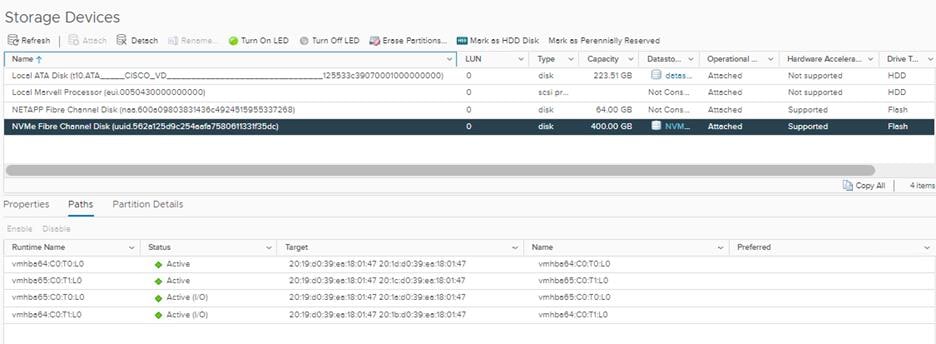
Step 3. For any of the three hosts, right-click the host under Hosts and Clusters and select Storage > New Datastore. Leave VMFS selected and click NEXT.
Step 4. Name the datastore and select the NVMe Fibre Channel Disk. Click NEXT.
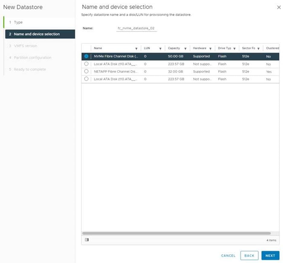
Step 5. Leave VMFS 6 selected and click NEXT.
Step 6. Leave all Partition configuration values at the default values and click NEXT.
Step 7. Review the information and click FINISH.
Step 8. Select Storage and select the just-created NVMe datastore. In the center pane, select Hosts. Ensure all three hosts have the datastore mounted.
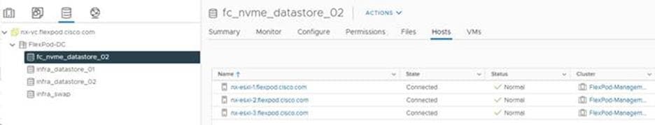
FlexPod Management Tools Setup
Cisco Intersight Hardware Compatibility List (HCL) Status
Cisco Intersight evaluates the compatibility of customer’s UCS system to check if the hardware and software have been tested and validated by Cisco or Cisco partners. Intersight reports validation issues after checking the compatibility of the server model, processor, firmware, adapters, operating system, and drivers, and displays the compliance status with the Hardware Compatibility List (HCL).
To determine HCL compatibility for VMware ESXi, Cisco Intersight uses Cisco UCS Tools. The Cisco UCS Tools is part of VMware ESXi Cisco custom ISO, and no additional configuration is required.
Note: For more details on Cisco UCS Tools manual deployment and troubleshooting, refer to: https://intersight.com/help/saas/resources/cisco_ucs_tools#about_cisco_ucs_tools
To find detailed information about the hardware compatibility of a compute node, in Cisco Intersight select Servers in the left menu bar, click a server, select HCL.
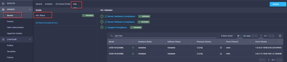
NetApp ONTAP Tools 9.10 Deployment Procedure
The ONTAP tools for VMware vSphere provide end-to-end life cycle management for virtual machines in VMware environments that use NetApp storage systems. It simplifies storage and data management for VMware environments by enabling administrators to directly manage storage within the vCenter Server.
This section describes the deployment procedures for the NetApp ONTAP Tools for VMware vSphere.
NetApp ONTAP Tools for VMware vSphere 9.10 Pre-installation Considerations
The following licenses are required for ONTAP Tools on storage systems that run ONTAP 9.8 or above:
● Protocol licenses (NFS, FCP, and/or iSCSI)
● NetApp FlexClone® ((optional) Required for performing test failover operations for SRA and for vVols operations of VASA Provider.
● NetApp SnapRestore® (for backup and recovery)
● The NetApp SnapManager® Suite - NetApp SnapMirror® or NetApp SnapVault® ((optional) Required for performing failover operations for SRA and VASA Provider if using vVols replication.)
Note: The Backup and Recovery capability has been integrated with SnapCenter and requires additional licenses for SnapCenter to perform backup and recovery of virtual machines and applications.
Table 15. Port Requirements for NetApp ONTAP Tools
| Port |
Requirement |
| 443 (HTTPS) |
Secure communications between VMware vCenter Server and the storage systems |
| 8143 (HTTPS) |
VSC listens for secure communications |
| 9083 (HTTPS) |
VASA Provider uses this port to communicate with the vCenter Server and obtain TCP/IP settings |
| 7 |
VSC sends an echo request to ONTAP to verify reachability and is required only when adding storage system and can be disabled later. |
The requirements for deploying NetApp ONTAP Tools (VSC) are listed here.
Download NetApp ONTAP Tools OVA
Download the NetApp ONTAP Tools 9.10 OVA (netapp-ontap-tools-for-vmware-vsphere-9.10-8127.ova) from NetApp support site: https://mysupport.netapp.com/site/products/all/details/otv/downloads-tab/download/63792/9.10
Procedure 1. Install NetApp ONTAP Tools utilizing Ansible
Step 1. Clone the repository from https://github.com/NetApp-Automation/ONTAP-Tools-for-VMware-vSphere
Step 2. Follow the instructions in the README file in the repository to ensure the Ansible environment is configured properly.
Step 3. Update the following variable files:
hosts
vars/ontap_tools_main.yml
group_vars/vcenter
Step 4. To invoke the ansible scripts use the following command:
ansible-playbook Setup_ONTAP_tools.yml -i hosts
Procedure 2. Install NetApp ONTAP Tools Manually
Step 1. Launch the vSphere Web Client and navigate to Hosts and Clusters.
Step 2. Select ACTIONS for the Epic-DC datacenter and select Deploy OVF Template.
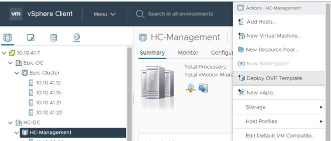
Step 3. Browse to the ONTAP tools OVA file(downloaded from the NetApp Support site) and select the file.
Step 4. Enter the VM name and select a datacenter or folder to deploy the VM and click NEXT.
Step 5. Select a host cluster resource to deploy OVA and click NEXT.
Step 6. Review the details and accept the license agreement.
Step 7. Select an appropriate datastore volume and select the Thin Provision option for the virtual disk format.
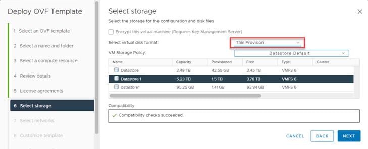
Step 8. From Select Networks, select a destination network and click NEXT.
Step 9. From Customize Template, enter the ONTAP tools administrator password, vCenter name or IP address and other configuration details and click NEXT.
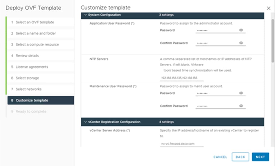
Step 10. Review the configuration details entered and click FINISH to complete the deployment of NetApp-ONTAP-Tools VM.
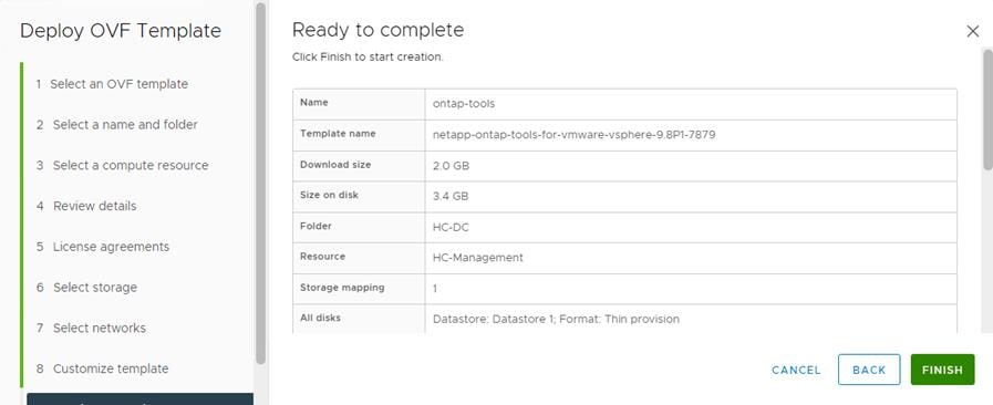
Step 11. Power on the ONTAP-tools VM and open the VM console.
Step 12. During the ONTAP-tools VM boot process, you see a prompt to install VMware Tools. From vCenter, right-click the ONTAP-tools VM > Guest OS > Install VMware Tools.
Step 13. Networking configuration and vCenter registration information was provided during the OVF template customization, therefore after the VM is up and running, ONTAP-Tools and vSphere API for Storage Awareness (VASA) is registered with vCenter.
Step 14. Refresh the vCenter Home Screen and confirm that the ONTAP tools is installed.
Note: The NetApp ONTAP tools vCenter plug-in is only available in the vSphere HTML5 Client and is not available in the vSphere Web Client.
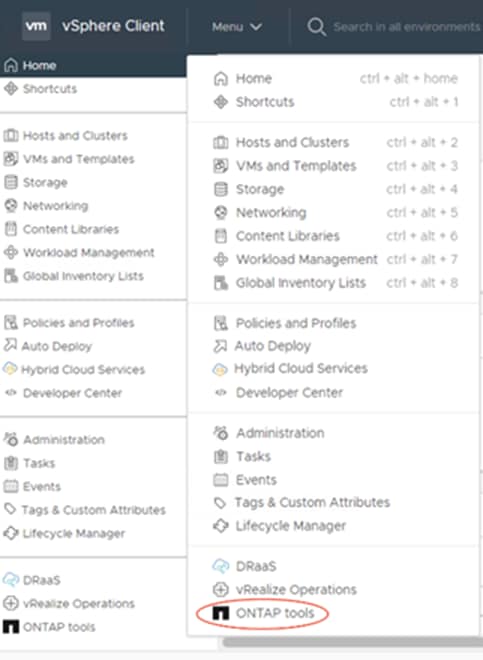
Procedure 3. Download the NetApp NFS Plug-in for VAAI
Step 1. Download the NetApp NFS Plug-in 2.0 for VMware .vib file from the NFS Plugin Download page and save it to your local machine or admin host.
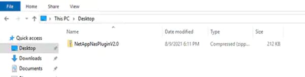
Procedure 4. Install the NetApp NFS Plug-in for VAAI
Note: If the NFS Plug-in for VAAI was previously installed on the ESXi hosts along with the Cisco UCS VIC drivers; it is not necessary to re-install.
Step 1. Rename the .vib file that you downloaded from the NetApp Support Site to NetAppNasPlugin.vib to match the predefined name that ONTAP tools uses.
Step 2. Click Settings in the ONTAP tool Getting Started page.
Step 3. Click NFS VAAI Tools tab.
Step 4. Click Change in the Existing version section.
Step 5. Browse and select the renamed .vib file, and then click Upload to upload the file to the virtual appliance.
Step 6. In the Install on ESXi Hosts section, select the ESXi host on which you want to install the NFS Plug-in for VAAI, and then click Install.
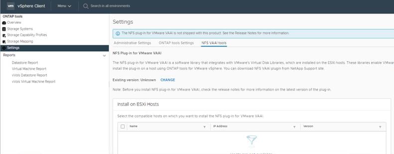
Step 7. Reboot the ESXi host after the installation finishes.
Procedure 5. Verify the VASA Provider
Note: The VASA provider for ONTAP is enabled by default during the installation of the NetApp ONTAP tools.
Step 1. From the vSphere Client, click Menu > ONTAP tools.
Step 2. Click Settings.
Step 3. Click Manage Capabilities in the Administrative Settings tab.
Step 4. In the Manage Capabilities dialog box, click Enable VASA Provider if it was not pre-enabled.
Step 5. If Enable VASA Provider is not enabled, click to enable then enter the IP address of the virtual appliance for ONTAP tools, VASA Provider, and VMware Storage Replication Adapter (SRA) and the administrator password, and then click Apply.
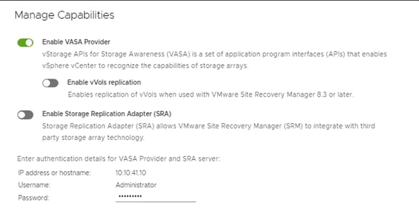
Procedure 6. Discover and Add Storage Resources
Step 1. Using the vSphere Web Client, log in to the vCenter. If the vSphere Web Client was previously opened, close the tab, and then reopen it.
Step 2. In the Home screen, click the Home tab and click ONTAP tools.
Note: When using the cluster admin account, add storage from the cluster level.
Note: You can modify the storage credentials with the vsadmin account or another SVM level account with role-based access control (RBAC) privileges. Refer to the ONTAP 9 Administrator Authentication and RBAC Power Guide for additional information.
Step 3. Click Storage Systems >Add
Step 4. Click Overview > Getting Started, and then click ADD under Add Storage System.
Step 5. Specify the vCenter Server instance where the storage will be located.
Step 6. In the IP Address/Hostname field, enter the storage cluster management IP.
Step 7. Confirm Port 443 to Connect to this storage system.
Step 8. Enter admin for the username and the admin password for the cluster.
Step 9. Click Save to add the storage configuration to ONTAP tools.
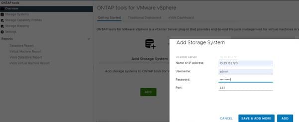
Step 10. Wait for the Storage Systems to update. You might need to click Refresh to complete this update.
Step 11. Discover the cluster and SVMs with the cluster admin account:
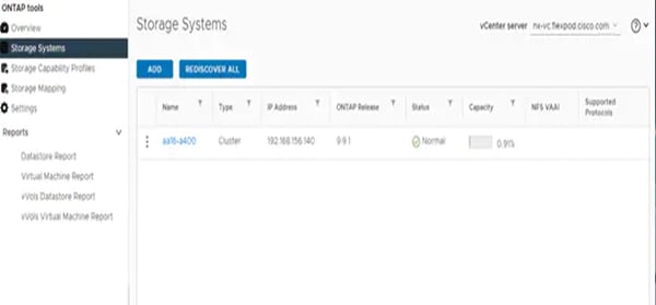
Step 12. From the vSphere Client Home page, click Hosts and Clusters.
Step 13. Right-click the Epic-DC datacenter, click NetApp ONTAP tools > Update Host and Storage Data.
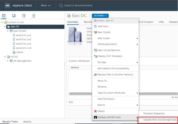
NetApp ONTAP tools displays a Confirm dialog box that informs you that this operation might take a few minutes.
Step 14. Click OK.
Procedure 7. Optimal Storage Settings for ESXi Hosts
Note: NetApp ONTAP tools enables the automated configuration of storage-related settings for all ESXi hosts that are connected to NetApp storage controllers.
Step 1. From the VMware vSphere Web Client Home page, click vCenter > Hosts and Clusters.
Step 2. Select a host and then click Actions > NetApp ONTAP tools > Set Recommended Values.
Step 3. In the NetApp Recommended Settings dialog box, select all the applicable values for the ESXi host.
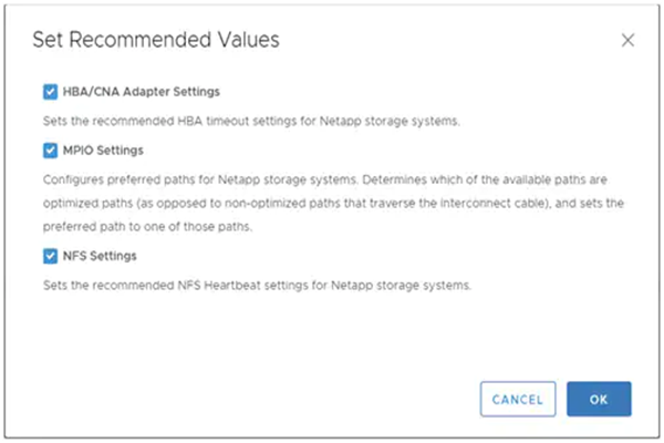
Note: This functionality sets values for HBAs and converged network adapters (CNAs), sets appropriate paths and path-selection plug-ins, and verifies appropriate settings for NFS I/O. A vSphere host reboot may be required after applying the settings.
Step 4. Click OK.
ONTAP Tools 9.10 Provisioning Datastores
Using ONTAP tools, the administrator can provision an NFS, FC, FC-NVMe or iSCSI datastore and attach it to a single host or multiple hosts in the cluster. The following sections describe provisioning a datastore and attaching it to the cluster.
Note: It is a NetApp best practice to use ONTAP tools to provision datastores for the FlexPod infrastructure. When using VSC to create vSphere datastores, all NetApp storage best practices are implemented during volume creation and no additional configuration is needed to optimize performance of the datastore volumes.
A storage capability is a set of storage system attributes that identifies a specific level of storage performance (storage service level), storage efficiency, and other capabilities such as encryption for the storage object that is associated with the storage capability.
Procedure 1. Create the Storage Capability Profile
Note: In order to leverage the automation features of VASA two primary components must first be configured. The Storage Capability Profile (SCP) and the VM Storage Policy. The Storage Capability Profile expresses a specific set of storage characteristics into one or more profiles used to provision a Virtual Machine. The SCP is specified as part of VM Storage Policy. NetApp ONTAP tools comes with several pre-configured SCPs such as Platinum, Bronze, and so on.
Note: The ONTAP tools for VMware vSphere plug-in also allows customers to set Quality of Service (QoS) rule using a combination of maximum and/or minimum IOPs.
Step 1. From the vCenter console, click Menu > ONTAP tools.
Step 2. In the NetApp ONTAP tools click Storage Capability Profiles.
Step 3. Select the Platinum Storage Capability Profile and select Clone from the toolbar.
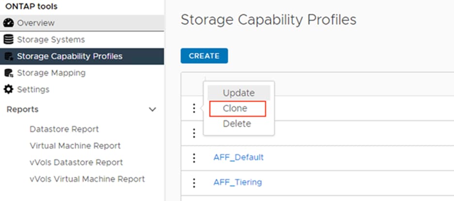
Step 4. Enter a name for the cloned SCP and add a description if desired. Click NEXT.
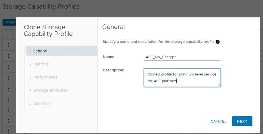
Step 5. Select All Flash FAS(AFF) for the storage platform and click NEXT.
Step 6. Select None to allow unlimited performance or set a the desired minimum and maximum IOPS for the QoS policy group. Click NEXT.
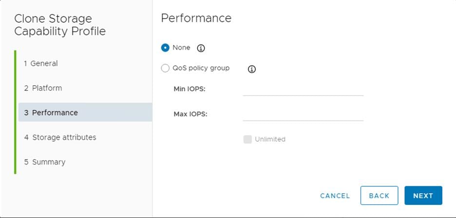
Step 7. On the Storage attributes page, Change the Encryption and Tiering policy to the desired settings and click NEXT.
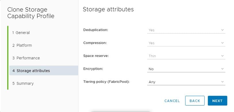
Step 8. Review the summary page and click FINISH to create the storage capability profile.
Note: It is recommended to Clone the Storage Capability Profile if you wish to make any changes to the predefined profiles rather than editing the built-in profile.
Procedure 2. Create a VM Storage Policy
Create a VM storage policy and associate a storage capability profile (SCP) to the datastore that meets the requirements defined in the SCP.
Step 1. From the vCenter console, click Menu > Policies and Profiles.
Step 2. Select VM Storage Policies and click CREATE.
Step 3. Create a name for the VM storage policy and enter a description and click NEXT.
Step 4. Choose Enable rules for NetApp.clustered.Data.ONTAP.VP.VASA10 storage located under the Datastore specific rules section and click NEXT.
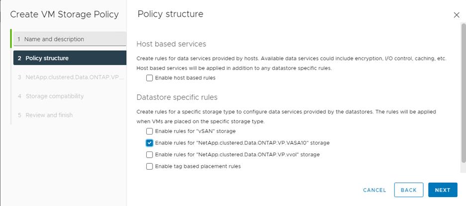
Step 5. On the Placement tab select the SCP created in the previous step and click NEXT.
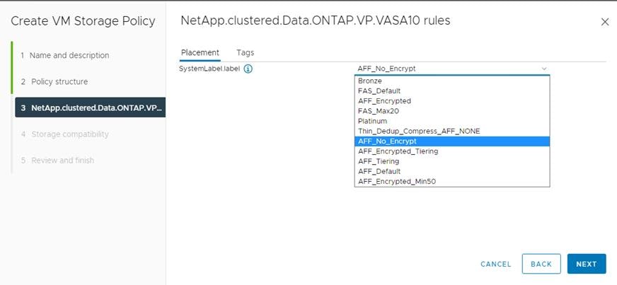
Step 6. All the datastores with matching capabilities are displayed, click NEXT.
Step 7. Review the policy summary and click FINISH.
Procedure 3. Provision NFS Datastore
Step 1. From the vCenter console, click Menu > ONTAP tools.
Step 2. From the ONTAP tools Home page, click Overview.
Step 3. In the Getting Started tab, click Provision.
Step 4. Click Browse to select the destination to provision the datastore.
Step 5. Select the type as NFS and Enter the datastore name.
Step 6. Provide the size of the datastore and the NFS Protocol.
Step 7. Check the storage capability profile and click NEXT.
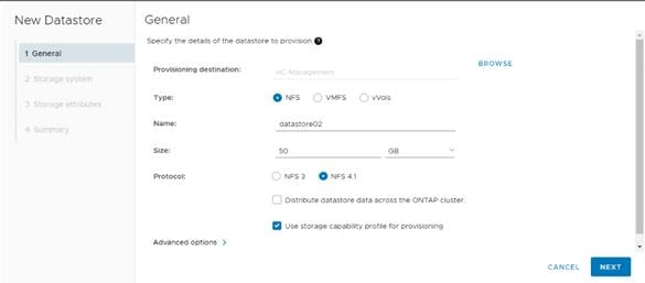
Step 8. Select the desired Storage Capability Profile, cluster name and the desired SVM to create the datastore.
Step 9. Click NEXT.
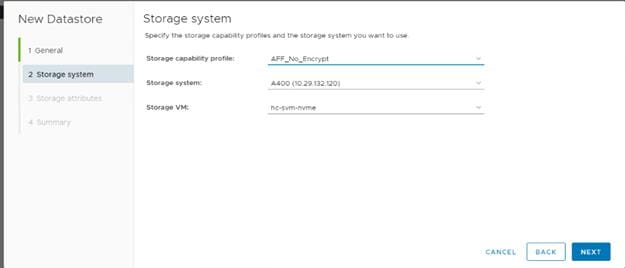
Step 10. Select the aggregate name and click NEXT.
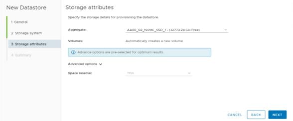
Step 11. Review the Summary and click FINISH.
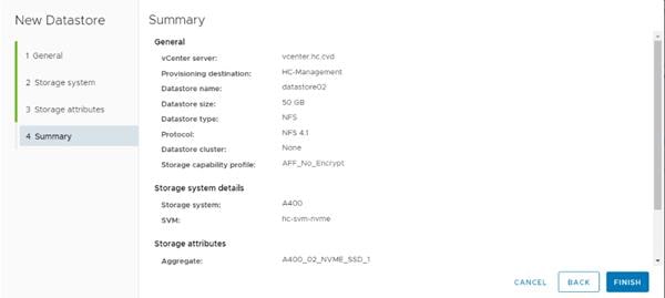
Note: The datastore is created and mounted on the hosts in the cluster. Click Refresh from the vSphere Web Client to see the newly created datastore or it is also listed in the ONTAP tools home page > Traditional Dashboard > Datastores view. Also, ONTAP tools home page > Reports > Datastore Report should list the newly created datastore.
Procedure 4. Provision FC Datastore
Step 1. From the vCenter console, click Menu > ONTAP tools.
Step 2. From the ONTAP tools Home page, click Overview.
Step 3. In the Getting Started tab, click Provision.
Step 4. Click Browse to select the destination to provision the datastore.
Step 5. Select the type as VMFS and Enter the datastore name.
Step 6. Provide the size of the datastore and the FC Protocol.
Step 7. Check the Use storage capability profile and click NEXT.
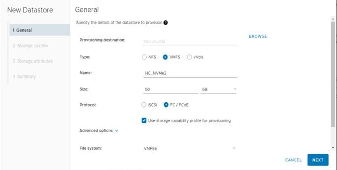
Step 8. Select the Storage Capability Profile, Storage System, and the desired Storage VM to create the datastore.
Step 9. Click NEXT.
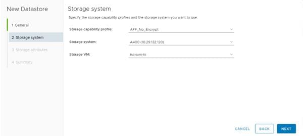
Step 10. Select the aggregate name and click NEXT.
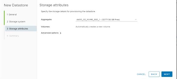
Step 11. Review the Summary and click FINISH.
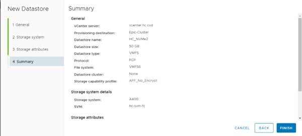
Step 12. Click OK.
Note: The datastore is created and mounted on all the hosts in the cluster. Click Refresh from the vSphere Web Client to see the newly created datastore.
Procedure 5. Create Virtual Machine with Assigned VM Storage Policy
Step 1. Log into vCenter and navigate to the VMs and Templates tab and click to select the datacenter (for example, HC-DC).
Step 2. Click Actions and click New Virtual Machine.
Step 3. Click Create a new virtual machine and click NEXT.
Step 4. Enter a name for the VM and click the HC-DC datacenter.
Step 5. Choose the HC-Management Data compute Resource.
Step 6. Select the VM storage policy from the selections and select a compatible datastore. Click NEXT.
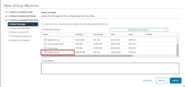
Step 7. Select Compatibility (for example, ESXi 7.0 U2 or later) and click NEXT.
Step 8. Select the Guest OS and click NEXT.
Step 9. Customize the hardware for the VM and click NEXT.
Step 10. Review the details and click FINISH.
Virtual Volumes (vVols)
NetApp VASA Provider enables customers to create and manage VMware virtual volumes (vVols). A vVols datastore consists of one or more FlexVol volumes within a storage container (also called "backing storage"). A virtual machine can be spread across one vVols datastore or multiple vVols datastores. All of the FlexVol volumes within the storage container must use the same protocol (NFS, iSCSI, or FCP) and the same SVMs.
Note: Lab testing has shown that if a virtual machine (VM) has one or more disks in vVol datastores and the VM is migrated to another host, under heavy load the VM can be stunned or frozen for 45 or more seconds.
Procedure 1. Verify NDMP Vserver Scope Mode
Step 1. View NDMP scope mode with the following command:
system services ndmp node-scope-mode status
Step 2. If NDMP node-scope is enabled, disable NDMP node-scoped mode:
system services ndmp node-scope-mode off
Step 3. Enable NDMP services on the vserver:
vserver add-protocols -protocols ndmp -vserver Infra_svm
vserver services ndmp on -vserver Infra_svm
Procedure 2. Create the Storage Capability Profile
Note: Select one or more VASA Provider storage capability profiles for a vVols datastore. A default storage capability profile can also be specified for any vVols datastores that are automatically created in that storage container.
Step 1. From the vCenter console, click Menu > ONTAP tools.
Step 2. From the ONTAP tools Home page, click Storage Capability Profiles.
Step 3. Select the Platinum Storage Capability Profile and select Clone from the toolbar.
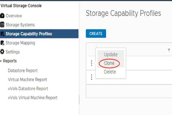
Step 4. Enter a name for the cloned SCP and add a description if desired. Click NEXT.
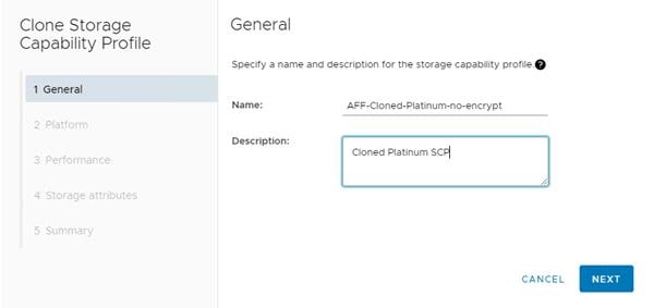
Step 5. Select All Flash FAS(AFF) for the storage platform and click NEXT.
Step 6. Select None to allow unlimited performance or set a the desired minimum and maximum IOPS for the QoS policy group. Selecting a value for Max IOPS enables customers to use the QoS functionality.
Note: When applied for a virtual datastore, a QoS policy with "MAX IOPS" value is created for each data vVols.
Note: When you select ONTAP Service Level, then the existing adaptive QoS policies of ONTAP are applied to a data vVols. You can select one of three service levels: Extreme, Performance, or Value. The ONTAP service level is applicable only to vVols datastores.
Step 7. On the Storage attributes page, change the Encryption and Tiering policy to the desired settings and click NEXT.
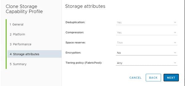
Step 8. Review the summary page and click FINISH to create the storage capability profile.
Procedure 3. Create a VM Storage Policy
Create a VM storage policy and associate a storage capability profile (SCP) to the datastore that meets the requirements defined in the SCP.
Step 1. From the vCenter console, click Menu > Policies and Profiles.
Step 2. Select VM Storage Policies and click Create VM Storage Policy.
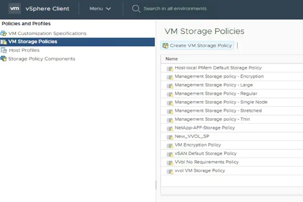
Step 3. Enter a new name for the VM storage Policy and click NEXT.
Step 4. Select Enable rules for NetApp.clustered.Data.ONTAP.VP.VASA.10 storage and NetApp.clustered.Data.ONTAP.VP.vvol storage, located under the Datastore specific rules section and click NEXT.
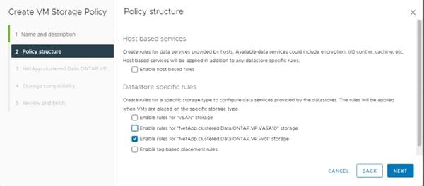
Step 5. Select a pre-defined SCP or SCP created in the previous step under BOTH NetApp.clustered.Data.ONTAP.VP.VASA10 and NetApp.clustered.Data.ONTAP.VP.vvol rules. Click NEXT.
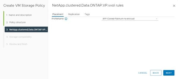
Step 6. The datastores with matching capabilities are displayed, click NEXT.
Step 7. Review the Policy Summary and click Finish.
Procedure 4. Provision a vVols Datastore
Step 1. From the vCenter console, click Menu > ONTAP tools.
Step 2. From the NetApp ONTAP tools Home page, click Overview.
Step 3. In the Getting Started tab, click Provision.
Step 4. Click Browse to select the destination cluster to provision the datastore.
Step 5. Select the type as vVols and enter the datastore name.
Step 6. Select NFS for protocol and click NEXT.
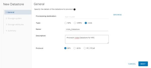
Step 7. Select the Storage capability profile previously created for vVols.
Step 8. Select the Storage system and the Storage SVM. Click NEXT.
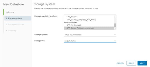
Step 9. Select Create new volumes.
Step 10. Enter the name and size for one or more vVols and Click ADD.
Note: You can create multiple vVols for a datastore.
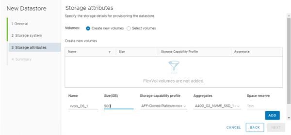
Step 11. Verify the correct Default storage capability profile is selected. Click NEXT.
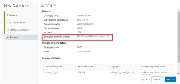
Step 12. Review all the fields on the summary page and click FINISH.
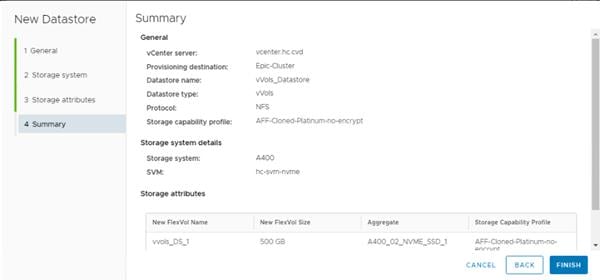
Step 13. Verify in the vVols Datastore report the vVols is mounted correctly, under ONTAP tools > Reports > vVols Datastore Report.
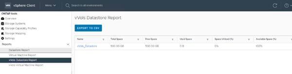
Note: vVols can also be configured for FC or ISCSI protocol using the steps outlined above and selecting a different protocol on the first screen.
Procedure 5. Update a vVols Datastore
Step 1. Go to the Storage tab in vCenter.
Step 2. Select the vVol datastore.
Step 3. Click ACTIONs.
Step 4. Under NetApp ONTAP tools:
a. Expand Storage on a vVols Datastore.
b. Remove Storage on a vVols Datastore.
c. Edit Properties of vVols Datastore.
d. Mount vVols Datastore.
e. Delete vVols Datastore.
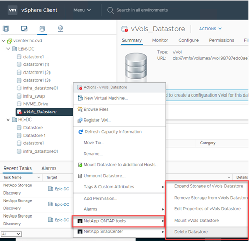
Procedure 6. Create a Virtual Machine on a vVols Datastore
Step 1. Navigate to vSphere Client > VMs and Templates > Actions > New Virtual Machine.
Step 2. Select Create a new virtual machine and click NEXT.
Step 3. Enter the name for the VM (for example, VM_VVOL_01) and select the datacenter (for example, Epic-DC). Click NEXT.
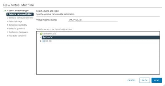
Step 4. Select the cluster and click NEXT.
Step 5. Select the VM Storage Policy and vVol datastore. Verify Compatibility checks succeeded.
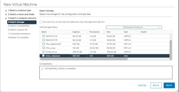
Step 6. Click NEXT.
Step 7. Select Compatibility (for example, ESXi 7.0 U3 and later) and click NEXT.
Step 8. Select Guest OS Family (for example, Linux) and Guest OS version (for example, Red Hat Enterprise Linux 9) and click NEXT.
Step 9. Select the hardware parameters (CPU, Memory, HDD and so on.) and click NEXT.
Step 10. Review the settings and click FINISH.
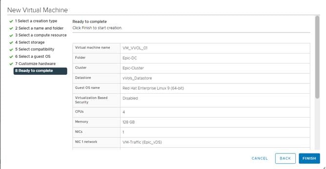
Step 11. Verify that the VM is created successfully and install operating system on the VM.
SnapCenter Software is a centralized and scalable platform that provides application-consistent data protection for applications, databases, host file systems, and VMs running on ONTAP systems anywhere in the Hybrid Cloud.
NetApp SnapCenter Architecture
The SnapCenter platform is based on a multitier architecture that includes a centralized management server (SnapCenter Server) and a SnapCenter host agent. The host agent that performs virtual machine and datastore backups for VMware vSphere is the SnapCenter Plug-in for VMware vSphere. It is packaged as a Linux appliance (Debian-based Open Virtual Appliance format) and is no longer part of the SnapCenter Plug-ins Package for Windows. Additional information on deploying SnapCenter server for application backups can be found below.
This CVD focuses on deploying and configuring the SnapCenter plug-in for VMware vSphere to protect virtual machines and VM datastores.
Note: Customers must install SnapCenter Server and the necessary plug-ins to support application-consistent backups for Microsoft SQL, Microsoft Exchange, Oracle databases and SAP HANA. Application-level protection is beyond the scope of this deployment guide.
Refer to the SnapCenter documentation for more information or the application specific CVD’s and technical reports for detailed information on how to deploy SnapCenter for a specific application configuration.
● SnapCenter Documentation: https://docs.netapp.com/us-en/snapcenter/index.html
● Deploy FlexPod Datacenter for Microsoft SQL Server 2019 with VMware 7.0 on Cisco UCS B200 M6 and NetApp ONTAP 9.8: https://www.cisco.com/c/en/us/products/collateral/servers-unified-computing/ucs-b-series-blade-servers/flexpod-sql-2019-vmware-on-ucs-netapp-ontap-wp.html
● SnapCenter Plug-in for VMware vSphere Documentation: https://docs.netapp.com/us-en/sc-plugin-vmware-vsphere-45/index.html
Install SnapCenter Plug-In 4.6 for VMware vSphere
NetApp SnapCenter Plug-in for VMware vSphere is a Linux-based virtual appliance which enables the SnapCenter Plug-in for VMware vSphere to protect virtual machines and VMware datastores.
Host and Privilege Requirements for the SnapCenter Plug-In for VMware vSphere
Review the following requirements before installing the SnapCenter Plug-in for VMware vSphere virtual appliance:
● SnapCenter Plug-in for VMware vSphere is deployed as a Linux based virtual appliance.
● Virtual appliance must be deployed on the vCenter Server.
● Virtual appliance must not be deployed in a folder name with special characters.
● A separate, unique instance of the virtual appliance must be deployed for each vCenter Server.
| Port |
Requirement |
| 8080(HTTPS) bidirectional |
This port is used to manage the virtual appliance |
| 8144(HTTPs) bidirectional |
Communication between SnapCenter Plug-in for VMware vSphere and vCenter |
| 443 (HTTPS) |
Communication between SnapCenter Plug-in for VMware vSphere and vCenter |
License Requirements for SnapCenter Plug-In for VMware vSphere
The following licenses are required to be installed on the ONTAP storage system to backup and restore VM’s in the virtual infrastructure:
Table 17. SnapCenter Plug-in for VMware vSphere License Requirements
| Product |
License Requirements |
| ONTAP |
SnapManager Suite: Used for backup operations One of these: SnapMirror or SnapVault (for secondary data protection regardless of the type of relationship) |
| ONTAP Primary Destinations |
To perform protection of VMware VMs and datastores the following licenses should be installed: SnapRestore: used for restoring operations FlexClone: used for mount and attach operations |
| ONTAP Secondary Destinations |
To perform protection of VMware VMs and datastores only: FlexClone: used for mount and attach operations |
| VMware |
vSphere Standard, Enterprise, or Enterprise Plus A vSphere license is required to perform restore operations, which use Storage vMotion. vSphere Essentials or Essentials Plus licenses do not include Storage vMotion. |
Note: It is recommended (but not required) to add SnapCenter Standard licenses to secondary destinations. If SnapCenter Standard licenses are not enabled on secondary systems, SnapCenter cannot be used after a failover operation. A FlexClone license on secondary storage is required to perform mount and attach operations. A SnapRestore license is required to perform restore operations.
Procedure 1. Download and Deploy the SnapCenter Plug-In 4.6 for VMware vSphere
Step 1. Download SnapCenter Plug-in for VMware vSphere OVA file from NetApp support site: (https://mysupport.netapp.com).
Procedure 2. Deploy the SnapCenter Plug-In 4.6 for VMware vSphere using Ansible
Step 1. Clone the repository from https://github.com/NetApp-Automation/SnapCenter-Plug-in-for-VMware-vSphere
Step 2. Follow the instructions in the README file in the repository to ensure the Ansible environment is configured properly.
Step 3. Update the following variable files:
hosts
vars/snapcenter_vmware_plugin_main.yml
group_vars/vcenter
Step 4. To invoke the ansible scripts use the following command:
ansible-playbook -i hosts Setup_SnapCenter_VMware_Plugin.yml
Procedure 3. Manually deploy the SnapCenter Plug-In 4.6 for VMware vSphere
Step 1. From VMware vCenter, navigate to the VMs and Templates tab, right-click the data center (for example, Epic-DC) and select Deploy OVF Template.
Step 2. Specify the location of the OVF Template and click NEXT.
Step 3. On the Select a name and folder page, enter a unique name (for example, NX-SNAPCTR) and location (data center for example, Epic-DC) for the VM and click NEXT to continue.
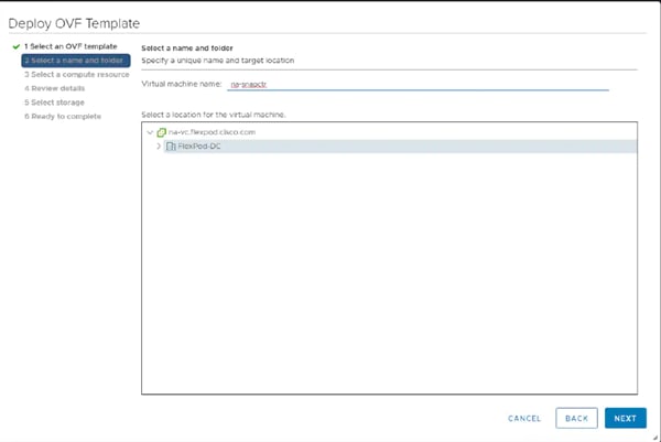
Step 4. On the Select a compute resource page, select the cluster, and click NEXT.
Step 5. On the Review details page, verify the OVA template details and click NEXT.
Step 6. On the License agreements page, read and check the box I accept all license agreements. Click NEXT.
Step 7. On the Select storage page, select a datastore, change the datastore virtual disk format to Thin Provision and click NEXT.
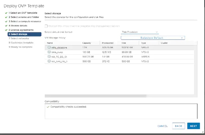
Step 8. On the Select networks page, select s destination network for example, IB-MGMT and then click NEXT.
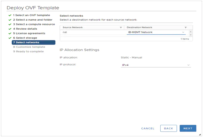
Step 9. On the Customize template page, under Register to existing vCenter, enter the vCenter credentials.
Step 10. In Create SCV credentials, create a username (for example, admin) and password for the SCV maintenance user.
Step 11. In Setup Network Properties, enter the network information.
Step 12. In Setup Date and Time, provide the NTP server address(es) and select the time zone where the vCenter is located.
Step 13. Click NEXT.
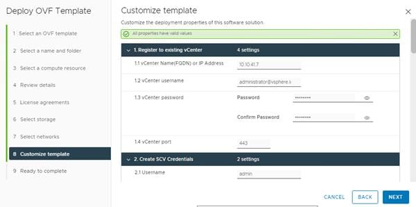
Step 14. On the Ready to complete page, review the page and click FINISH. The VM deployment will start. After the VM is deployed successfully, proceed to the next step.
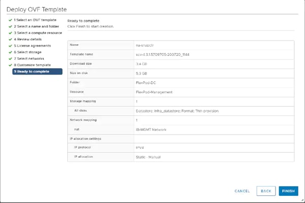
Step 15. Navigate to the SnapCenter VM, right-click, and select Power > Power On to start the virtual appliance.
Step 16. While the virtual appliance is powering on, click Install VMware tools.
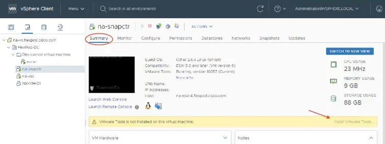
Step 17. After the SnapCenter VM installation is complete and VM is ready to use, proceed to the next step.
Step 18. Log into SnapCenter Plug-in for VMware vSphere using the IP address (https://<ip_address_of_SnapCenter>:8080 ) displayed on the appliance console screen with the credentials that you provided in the deployment wizard.
Step 19. Verify on the Dashboard that the virtual appliance has successfully connected to vCenter and the SnapCenter Plug-in for VMware vSphere is successfully enabled and connected.
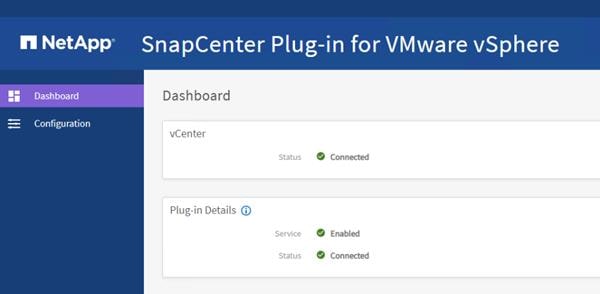
Procedure 4. SnapCenter Plug-In for VMware vSphere in vCenter Server
Note: After successfully installing the SnapCenter Plug-in for VMware vSphere, configure SnapCenter and make it ready to backup virtual machines.
Step 1. Navigate to VMware vSphere Web Client URL https://<vCenter Server>.
Note: If currently logged into vCenter, logoff, close the open tab and sign-on again to access the newly installed SnapCenter Plug-in for VMware vSphere.
Step 2. After logging on, a blue banner will be displayed indicating the SnapCenter plug-in was successfully deployed. Click Refresh to activate the plug-in.
Step 3. On the VMware vSphere Web Client page, select Menu > SnapCenter Plug-in for VMware vSphere to launch the SnapCenter Plug-in for VMware GUI.
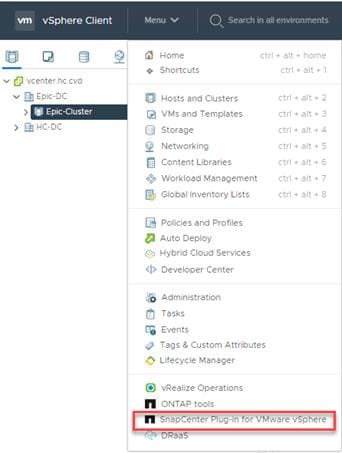
Procedure 5. Add Storage System
Step 1. Click Storage Systems.
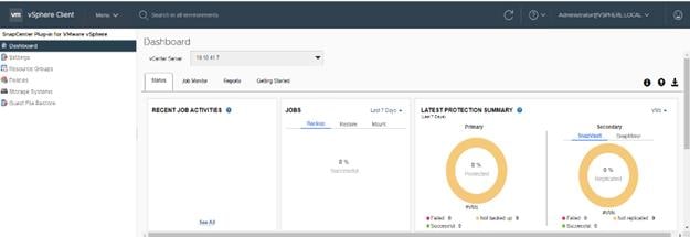
Step 2. Click Add Storage System to add a cluster or SVM.
Step 3. Enter vCenter, Storage System, user credentials, and other required information in following dialog box.
Step 4. Check the box for Log SnapCenter server events to syslog and Send AutoSupport Notification for failed operation to storage system.
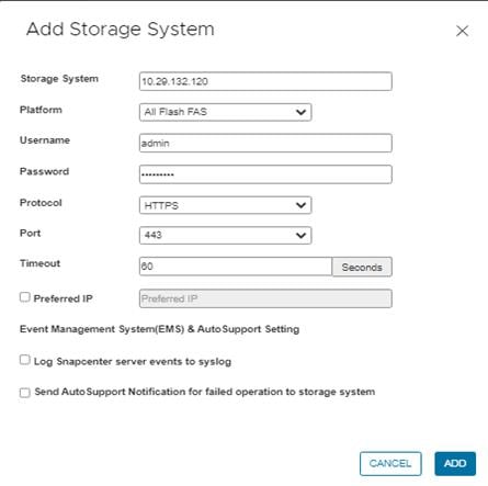
Step 5. Click ADD.
Procedure 6. Create Backup Policies for Virtual Machines and Datastores
Step 1. From SnapCenter GUI, Click Policies.
Step 2. On the Policies page, click +Create to create a new policy.
Step 3. On the New Backup Policy page, follow these steps:
Step 4. Enter the policy name and a description.
Step 5. Enter the backups to keep.
Step 6. From the Frequency drop-down list, select the backup frequency (hourly, daily, weekly, monthly, and on-demand only).
Step 7. Expand the Advanced options and select VM Consistency and Include datastore with independent disks.
Step 8. Click ADD.
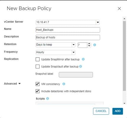
Note: Customers can create multiple policies as required for different sets of VMs or datastores.
Procedure 7. Create Resource Groups
Resource groups are groups of virtual machines or datastores that are backed up together. A backup policy is associated with the resource group to back up the virtual machines and retain a certain number of backups as defined in the policy.
Step 1. In SnapCenter Plug-in Navigator, click Resource Groups.
Step 2. Click +Create to create a new Resource Group.
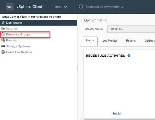
Note: To create a resource group for one virtual machine, click VMs and Templates, right-click a virtual machine, select NetApp SnapCenter from the drop-down list, and then select Create Resource Group from the secondary drop-down list.
Note: To create a resource group for one datastore, click Storage, right-click a datastore, select NetApp SnapCenter from the drop-down list, and then select Create Resource Group from the secondary drop-down list.
Step 3. In the General Info & notification page, enter the resource group name and complete the notification settings.
Step 4. Select the Custom snapshot format option and select the desired label for example, $ResourceGroup to have the resource group name appended to the snapshot name during snapshot operation.
Step 5. Click NEXT.
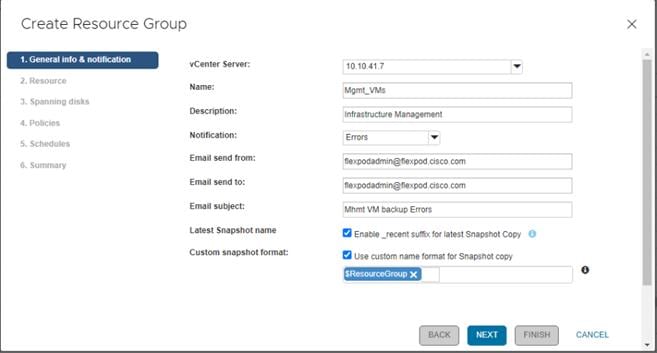
Step 6. Select a datastore as the parent entity to create a resource group of virtual machines.
Step 7. Select the virtual machines from the available list. Click NEXT.
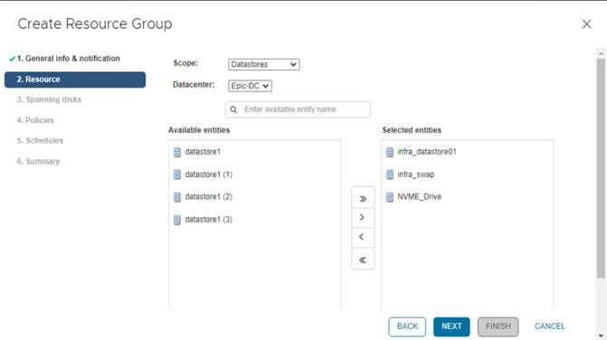
Note: Entire datastores can be backed up by selecting data center (for example, Epic-DC) in the parent entity list box and selecting/adding the datastore.
Step 8. From the Spanning Disks options, select the Always include all spanning datastores option and click NEXT.
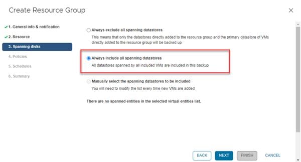
Step 9. From the Policies tab, select the policy created in the last step to associate the policy with the resource group and click NEXT.
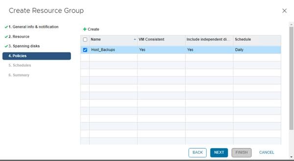
Step 10. From Schedules, select the schedule for the selected policy and click NEXT.
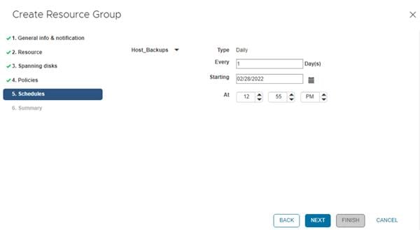
Step 11. Review the summary and click FINISH to complete the creation of the resource group.
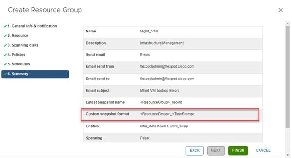
Procedure 8. View Virtual Machine Backups from vCenter by Using SnapCenter Plug-In
Backups of the virtual machines included in the resource group occurs according to the schedule of the policies associated with the resource group.
Step 1. Log into the VMware vCenter GUI.
Step 2. Navigate to the VMs and Templates tab.
Step 3. Select a VM that is the member of the previously created Resource Group.
Step 4. Select the Configure tab.
Step 5. Under SnapCenter Plug-in for vSphere, select the Backups tab to view all the backups available for the VM.
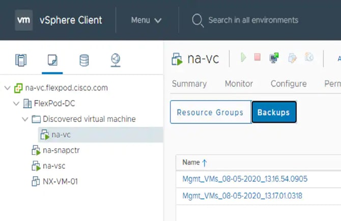
Step 6. Navigate to Menu > SnapCenter Plug-in for VMware vSphere and select Dashboard to view recent job activity, backup jobs and configuration details.
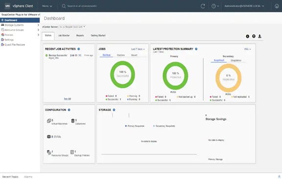
Step 7. Click Resource Groups and select a resource group. In the right pane, the completed backups are displayed.
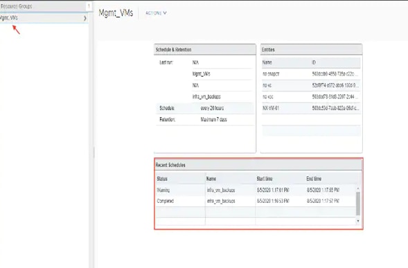
Procedure 9. Create On-Demand Backup
Step 1. From the vCenter GUI, select Menu > SnapCenter Plugin for VMware vSphere.
Step 2. Click Resource Groups.
Step 3. Select a resource group and click Run Now to run the backup immediately.
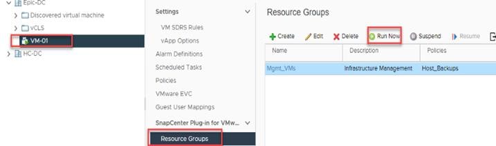
Procedure 10. Restore from vCenter by Using SnapCenter Plug-In
Note: The SnapCenter Plug-in for VMware vSphere provides native backup, recovery, and cloning of virtualized applications.
Step 1. Log into VMware vCenter.
Step 2. Navigate to VMs and Templates, select a VM and right-click to access the context menu. Select NetApp SnapCenter > Restore.
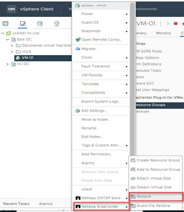
Step 3. Select a backup to restore. Click Next.
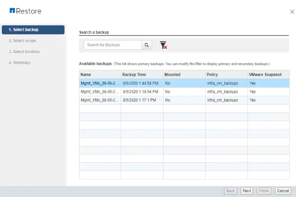
Step 4. From the Restore Scope drop-down list, select either Entire virtual machine to restore the virtual machine with all Virtual Machine Disks (VMDKs) or select Particular Virtual Disk to restore the VMDK without affecting the virtual machine configuration and other VMDKs.
Step 5. Select the ESXi host that the VM should be restored to and check the box to restart the VM (if needed).
Step 6. Click NEXT.
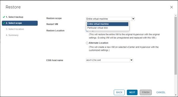
Step 7. Select the destination datastore and click NEXT.
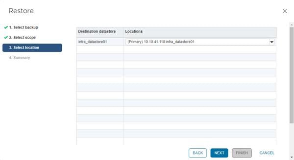
Step 8. Review the Summary and click FINISH to complete the restore process.
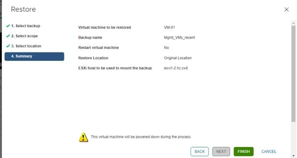
NetApp Active IQ Unified Manager 9.10
NetApp Active IQ Unified Manager enables customers to monitor and manage the health and performance of ONTAP storage systems and virtual infrastructure from a single interface. NetApp Active IQ Unified Manager provides a graphical interface that displays the capacity, availability, protection, and performance status of the monitored storage systems. NetApp Active IQ Unified Manager is required to integrate NetApp storage with Cisco Intersight.
This section describes the steps to deploy NetApp Active IQ Unified Manager 9.10 as a virtual appliance. The following table lists the recommended configuration for the virtual machine to install and run NetApp Active IQ Unified Manager to ensure acceptable performance.
Table 18. Virtual Machine Configuration
| Hardware Configuration |
Recommended Settings |
| RAM |
12 GB |
| Processors |
4 CPUs/ vCPUs |
| CPU Cycle Capacity |
9572 MHz total |
| Free Disk Space/virtual disk size |
5 GB - Thin provisioned |
|
|
152 GB - Thick provisioned |
Note: There is a limit to the number of nodes that a single instance of NetApp Active IQ Unified Manager can monitor before you need to install a second instance of NetApp Active IQ Unified Manager. See the Unified Manager Best Practices Guide (TR-4621) for more details.
Procedure 1. Install NetApp Active IQ Unified Manager 9.10 using Ansible
Step 1. Follow the Pre-Requisites from https://github.com/NetApp-Automation/NetApp-AIQUM
Step 2. Download ansible git: git clone https://github.com/NetApp-Automation/NetApp-AIQUM.git
Step 3. To invoke the ansible scripts use the following command:
ansible-playbook aiqum.yml -t aiqum_setup
Procedure 2. Install NetApp Active IQ Unified Manager 9.10 Manually
Step 1. Download NetApp Active IQ Unified Manager for VMware vSphere OVA file from:
Step 2. https://mysupport.netapp.com/site/products/all/details/activeiq-unified-manager/downloads-tab.
Step 3. In the VMware vCenter GUI, click VMs and Templates and then click Actions> Deploy OVF Template.
Step 4. Specify the location of the OVF Template and click NEXT.
Step 5. On the Select a name and folder page, enter a unique name for the VM, and select a deployment location, and then click NEXT.
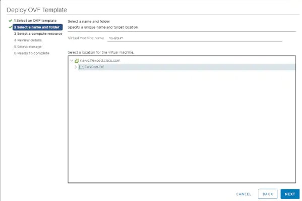
Step 6. On the Select a compute resource screen, select the cluster where VM will be deployed and click NEXT.
Step 7. On the Review details page, verify the OVA template details and click NEXT.
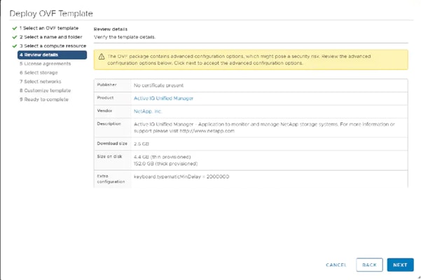
Step 8. On the License agreements page, read and check the box for I accept all license agreements. Click NEXT.
Step 9. On the Select storage page, select following parameters for the VM deployment:
a. Select the disk format for the VMDKs (for example, Think Provisioning).
b. Select a VM Storage Policy (for example, Datastore Default).
c. Select a datastore to store the deployed OVA template (for example, infra_datastore_2).
Step 10. Click NEXT.
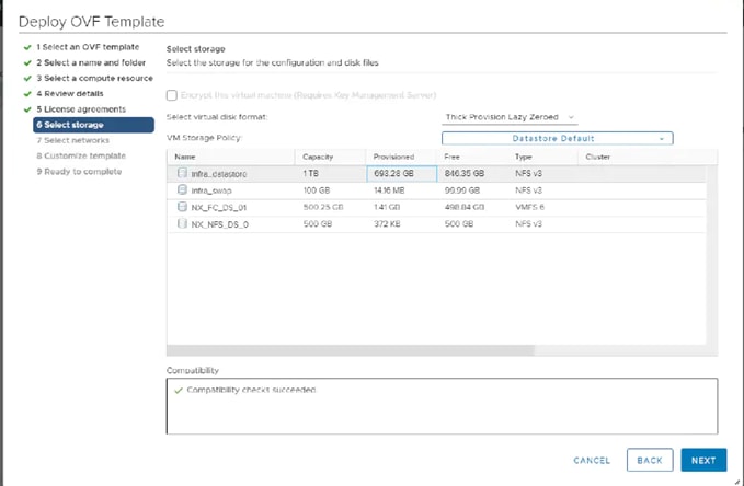
Step 11. On the Select networks page, select the destination network (for example, IB-MGMT) and click NEXT.
Step 12. On the Customize template page, provide network details such as hostname, IP address, gateway, and DNS.
Step 13. Click NEXT.
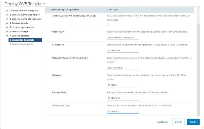
Note: Scroll through the customization template to ensure all required values are entered.
Step 14. On the Ready to complete page, review the settings and click FINISH. Wait for the VM deployment to complete before proceeding to the next step.
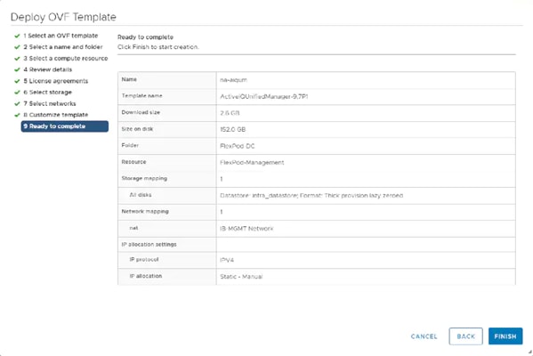
Step 15. Select the newly created NetApp Active IQ Unified Manager VM, right-click and select Power > Power On.
Step 16. While the virtual machine is powering on, click the prompt in the yellow banner to Install VMware tools.
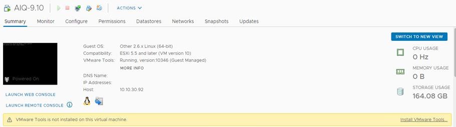
Note: Because of timing, VMware tools might not install correctly. In that case VMware tools can be manually installed after NetApp Active IQ Unified Manager VM is up and running.
Step 17. Open the VM console for the NetApp Active IQ Unified Manager VM and configure the time zone information when displayed.
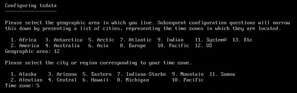
Step 18. Create a maintenance user account when prompted by specifying a user account name and password.
Note: Save the maintenance user account credentials in a secure location. These credentials will be used for the initial GUI login and to make any configuration changes to the appliance settings in future.
Note: If the systems complaints about Network information not valid, enter the values for hostname, IP address and DNS information when prompted.
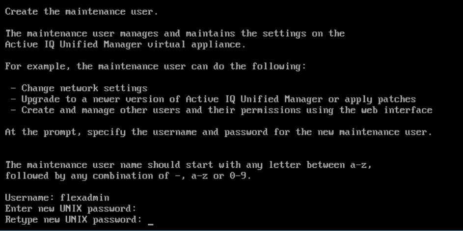
Step 19. Log into NetApp Active IQ Unified Manager using the IP address or URL displayed on the deployment screen using the maintenance user credentials created in the last step.
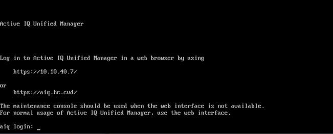
Procedure 3. Configure NetApp Active IQ Unified Manager
Step 1. Launch a web browser and log into NetApp Active IQ Unified Manager.
Step 2. Enter the email address that Unified Manager will use to send alerts, enter the mail server configuration, and the IP address or hostname of the NTP server. Click Continue and complete the AutoSupport configuration.
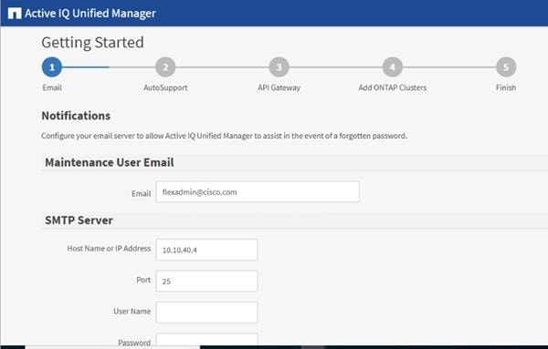
Step 3. Configure AutoSupport for Unified Manager by clicking Agree and Continue.
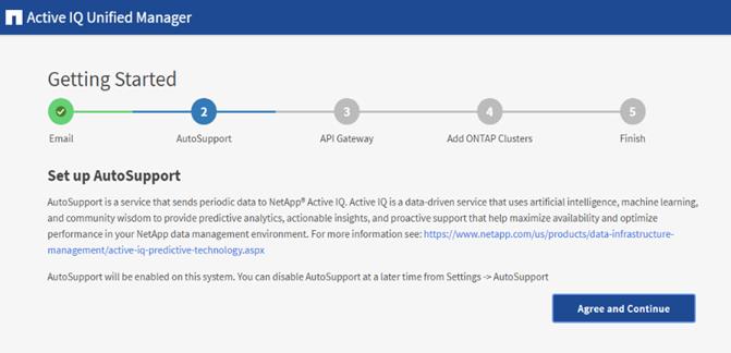
Step 4. Check the box for Enable API Gateway and click Continue to setup the API gateway for NetApp Active IQ Unified Manager.
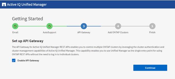
Step 5. Enter the ONTAP cluster hostname or IP address and the admin login credentials then click Add.
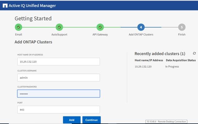
Step 6. A security prompt will be displayed to authorize the cluster certificate. Click Yes to trust the certificate.
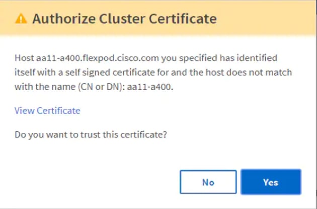
Step 7. When prompted to trust the self-signed certificate from Active IQ Unified Manager, click Yes to finish and add the storage system.
Note: The initial discovery process can take up to 15 minutes to complete.
Procedure 4. Add Local Users to NetApp Active IQ Unified Manager
Step 1. Navigate to the General section and click Users.
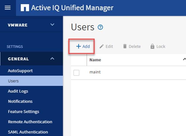
Step 2. Click Add and complete the requested information:
a. Select Local User for the Type.
b. Enter a username and password.
c. Add the user’s email address.
d. Select the appropriate role for the new user.
Step 3. Click Save to add the new user to NetApp Active IQ Unified Manager.
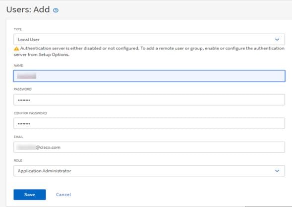
Procedure 5. Configure Remote Authentication
Simplify user management and authentication for Active IQ Unified Manager by integrating it with Microsoft Active Directory. Connect the Active IQ Unified Manager to Active Directory and perform user authentication with the Active Directory domain.
Note: You must be logged on as the maintenance user created during the installation or another user with Application Administrator privileges to configure remote authentication.
Step 1. Navigate to the General section and click Remote Authentication.
Step 2. Select the option to Enable remote authentication and define a remote user or remote group.
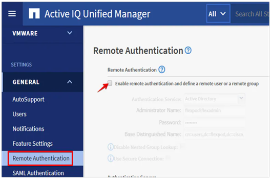
Step 3. Select Active Directory from the authentication service list.
Step 4. Enter the Active Directory service account name and password. The account name can be in the format of domain\user or user@domain.
Step 5. Enter the base DN where your Active Directory users reside.
Step 6. If Active Directory LDAP communications are protected via SSL enable the Use Secure Connection option.
Step 7. Add one or more Active Directory domain controllers by clicking Add and entering the IP or FQDN of the domain controller.
Step 8. Click Save to enable the configuration.
Note: If you don’t know the base DN to your Active Directory user organizational unit, contact the Active Directory administrator at your organization to provide this information.
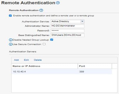
Step 9. Click Test Authentication and enter an Active Directory username and password to test authentication with the Active Directory authentication servers.
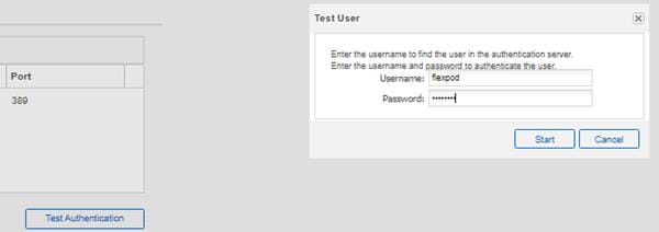
A result message displays indicating authentication was successful:
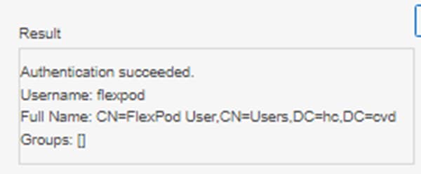
Procedure 6. Add a Remote User to NetApp Active IQ Unified Manager
Step 1. Navigate to the General section and click Users.
Step 2. Click Add and click Remote User from the Type drop-down list.
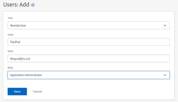
Step 3. Enter the following information into the form:
a. The username of the Active Directory user.
b. Email address of the user.
c. Select the appropriate role for the user
Step 4. Click Save when finished to add the remote user to NetApp Active IQ Unified Manager.
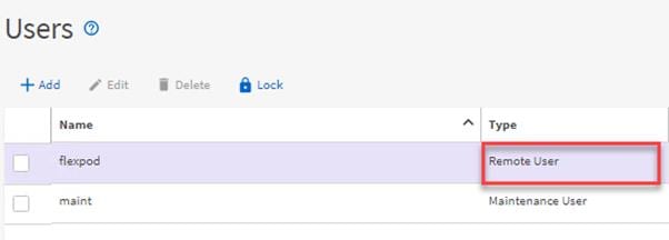
Procedure 7. Add the vCenter Server to NetApp Active IQ Unified Manager
NetApp Active IQ Unified Manager provides visibility into vCenter and the virtual machines running inside the datastores backed by ONTAP storage. Virtual machines and storage are monitored to enable fast identification of performance issues within the various components of the virtual infrastructure stack.
Note: Before adding vCenter into NetApp Active IQ Unified Manager, the log level of the vCenter server must be changed.
Step 1. In the vSphere client navigate to VMs and Templates and select the vCenter instance from the top of the object tree.
Step 2. Click the Configure tab, expand the settings, and click General.
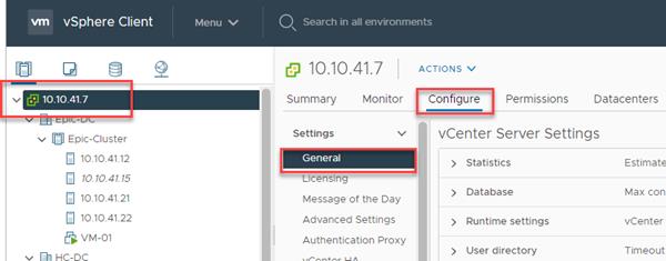
Step 3. Click EDIT.
Step 4. In the pop-up window under Statistics, locate the 5 minutes Interval Duration row and change the setting to Level 3 under the Statistics Level column. Click SAVE.
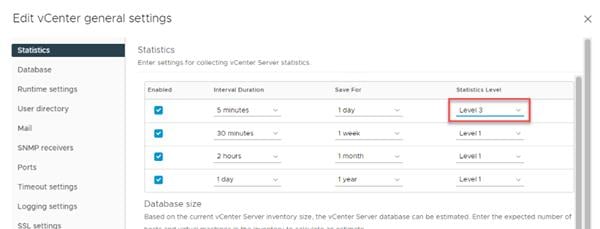
Step 5. Return to Active IQ Unified Manager and navigate to the VMware section located under Inventory.
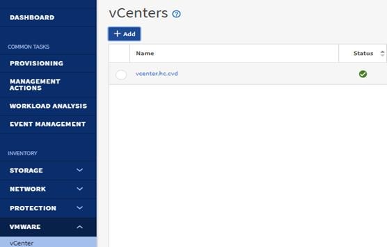
Step 6. Expand the section and select vCenter and click Add.
Step 7. Enter the VMware vCenter server details and click Save.
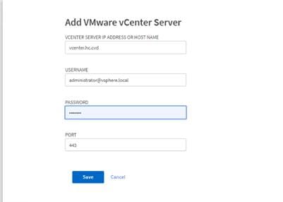
Step 8. A dialog box will appear asking to authorize the certificate. Click Yes to accept the certificate and add the vCenter server.
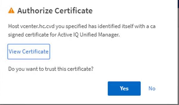
Note: It may take up to 15 minutes to discover the vCenter server. Performance data can take up to an hour after discovery to become available.
Procedure 8. View Virtual Machine Inventory
Note: The virtual machine inventory is automatically added to NetApp Active IQ Unified Manager during discovery of the vCenter server. Virtual machines can be viewed in a hierarchical display detailing storage capacity, IOPS and latency for each component in the virtual infrastructure to troubleshoot the source of any performance related issues.
Step 1. Navigate to the VMware section located under Inventory, expand the section, and click Virtual Machines.
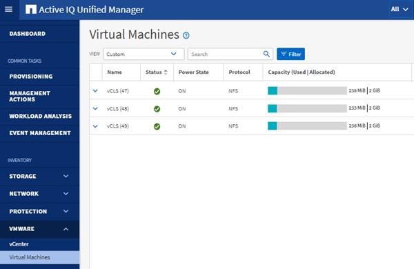
Step 2. Select a VM and click the blue caret to expose the topology view. Review the compute, network, and storage components and their associated IOPS and latency statistics.
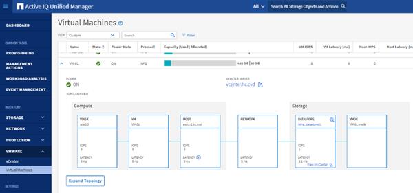
Step 3. Click Expand Topology to see the entire hierarchy of the virtual machine and its virtual disks as it is connected through the virtual infrastructure stack. The VM components are mapped from vSphere and compute through the network to the storage.
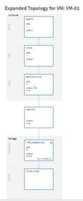
Procedure 9. Review Security Compliance with NetApp Active IQ Unified Manager
NetApp Active IQ Unified Manager identifies issues and makes recommendations to improve the security posture of ONTAP. NetApp Active IQ Unified Manager evaluates ONTAP storage based on recommendations made in the Security Hardening Guide for ONTAP 9. Items are identified according to their level of compliance with the recommendations. All events identified do not inherently apply to all environments, for example, FIPS compliance. Review the Security Hardening Guide for NetApp ONTAP 9 (TR-4569) for additional information and recommendations for securing ONTAP 9.
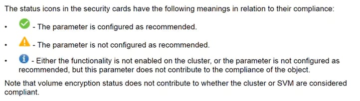
Step 1. Navigate to the URL of the Active IQ Unified Manager installation and login.
Step 2. Select the Dashboard from the left menu bar in Active IQ Unified Manager.
Step 3. Locate the Security card and note the compliance level of the cluster and SVM. Click the blue arrow to expand the findings.
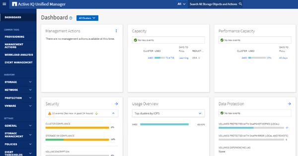
Step 4. Locate Individual Cluster section and the Cluster Compliance card. From the drop-down list select View All.
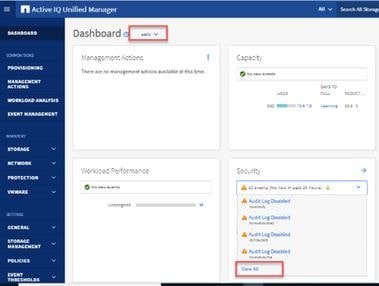
Step 5. Select an event from the list and click the name of the event to view the remediation steps.
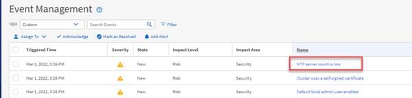
Step 6. Remediate the risk if desired and perform the suggested actions to fix the issue.
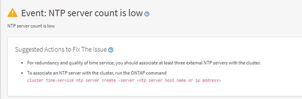
Remediate Security Compliance Findings
NetApp Active IQ identifies several security compliance risks after installation that can be immediately corrected to improve the security posture of ONTAP.
Procedure 1. Correct Cluster Risks
Step 1. To associate an NTP server with the cluster, run the ONTAP command:
cluster time-service ntp server create -server <ntp server host name or ip address>
Step 2. Enable the login banner on the cluster:
security login banner modify -vserver <clustername> -message "Access restricted to authorized users"
NetApp Active IQ is a data-driven service that leverages artificial intelligence and machine learning to provide analytics and actionable intelligence for ONTAP storage systems. NetApp Active IQ uses AutoSupport data to deliver proactive guidance and best practices recommendations to optimize storage performance and minimize risk.
Additional NetApp Active IQ documentation is available on the Active IQ Documentation Resources web page.
Procedure 1. Install NetApp Active IQ
Note: NetApp Active IQ is automatically enabled when you configure AutoSupport on the ONTAP storage controllers.
Step 1. Obtain the controller serial numbers from your ONTAP system with the following command:
system node show -fields serialnumber
Step 2. Navigate to the Active IQ portal at https://activeiq.netapp.com/
Step 3. Login with you NetApp support account ID.
Step 4. At the welcome screen enter the cluster name or one of controller serial numbers in the search box. NetApp Active IQ will automatically begin searching for the cluster and display results below.
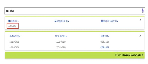
Step 5. Select the cluster name to launch the main dashboard.
Step 6. From the drop-down list select Set Page as Default Landing View.
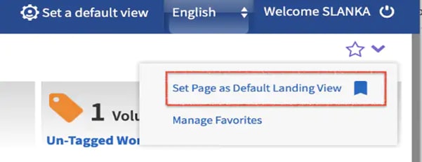
Procedure 2. Add a Watchlist to the Discovery Dashboard
Note: The system level dashboard is the default view for systems in NetApp Active IQ.
Step 1. Click Discovery Dashboard in the toolbar at the top of the NetApp Active IQ screen.
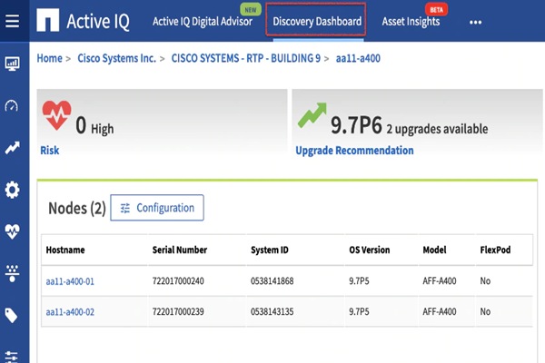
Step 2. Click Create Watchlist and enter a name for the watchlist.
Step 3. Select the radio button to add systems by serial number and enter the cluster serial numbers to the watchlist.
Step 4. Check the box for Make this my default watchlist if desired and click Create Watchlist.
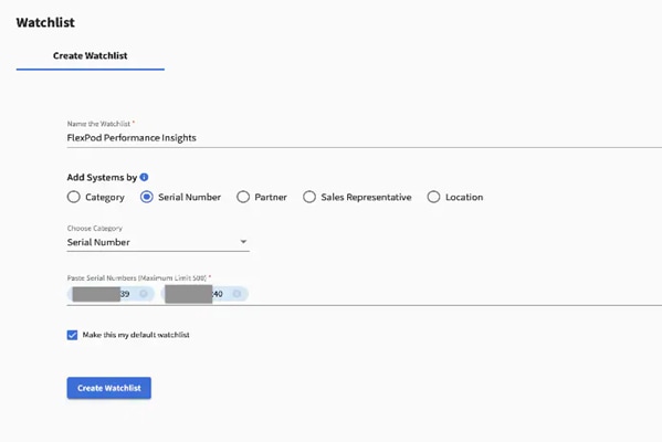
Step 5. Click Manage watchlists and then click the ellipsis on the cluster watchlist card you created and click View in Discovery Dashboard.
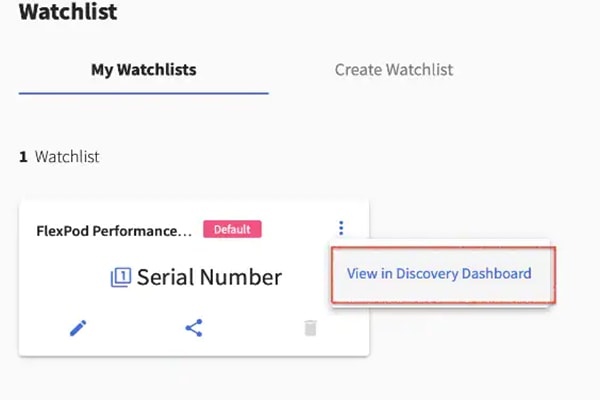
Step 6. View the health and risk overview for the cluster.
Procedure 3. Create Active IQ Digital Advisor Dashboard
The Active IQ Digital advisor provides a summary dashboard and system wellness score based on the health and risks that Active IQ have identified. The dashboard provides a quick way to identify and get proactive recommendations on how to mitigate risks in the storage environment including links to technical reports and mitigation plans.
Step 1. At the cluster dashboard, click Active IQ Digital Advisor from the top menu.
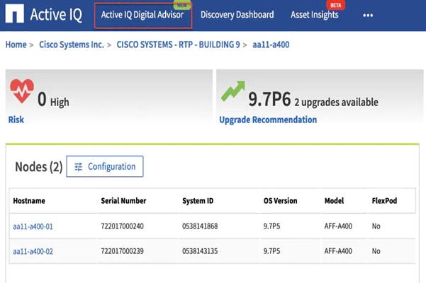
Step 2. Select the watchlist created in the previous step and click Next.
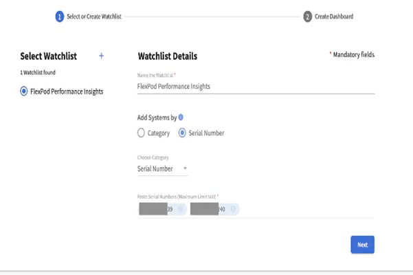
Step 3. Accept the dashboard default name and select all the available widgets.
Step 4. Check the box Make this the default dashboard and click Create.
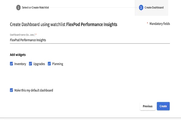
Step 5. Review the enhanced dashboard including the Wellness Score and any recommended actions or risks.
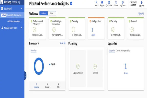
Step 6. Switch between the Actions and Risks tabs to view the risks broken down by category or a list of all risks with their impact and links to corrective actions.
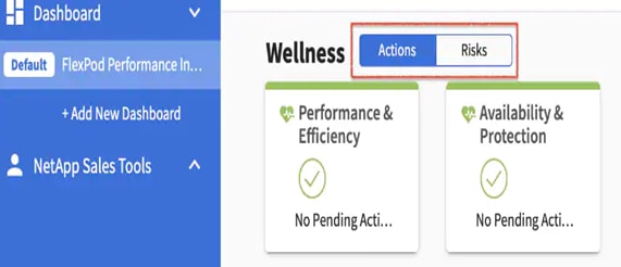
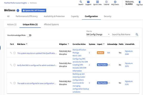
Step 7. Click the link in the Corrective Action column to read the bug information or knowledge base article about how to remediate the risk.
Note: Additional tutorials and video walk-throughs of Active IQ features can be viewed on the Active IQ documentation web page.
Deploy Cisco Intersight Assist Appliance
Cisco IntersightTM is a management platform delivered as a service with embedded analytics for your Cisco and third-party IT infrastructure. This platform offers an intelligent level of management that enables IT organizations to analyze, simplify, and automate their environments in more advanced ways than the prior generations of tools. Cisco Intersight provides an integrated and intuitive management experience for resources in the traditional data center and at the edge. With flexible deployment options to address complex security needs, getting started with Intersight is quick and easy.
Cisco Intersight offers flexible deployment either as Software as a Service (SaaS) on Intersight.com or running on your premises as Cisco Intersight Virtual Appliance. The virtual appliance provides the benefits of Cisco Intersight while allowing more flexibility for those with additional data locality and security requirements. The remainder of this section details Intersight deployment as SaaS on Intersight.com. To learn more about the virtual appliance, see the Cisco Intersight Virtual Appliance Getting Started Guide.
Procedure 1. Configure Cisco Intersight
Step 1. If you do not already have a Cisco Intersight account, to claim your Cisco UCS system into a new account on Cisco Intersight, connect to https://intersight.com. If you have an existing Intersight account, connect to https://intersight.com and sign in with your Cisco ID, select the appropriate account, and skip to step 6.
Step 2. Click Create an account.
Step 3. Sign in with your Cisco ID.
Step 4. Read, scroll through, and accept the End User License Agreement and click Next.
Step 5. Enter an Account Name and click Create.
Step 6. Click ADMIN > Targets. Click Claim Target. Select Cisco UCS Domain (UCSM Managed) and click Start. Fill in the Device ID and Claim Code and click Claim. The Device ID and Claim Code can be obtained by connecting to Cisco UCS Manager and selecting Admin > All > Device Connector. The Device ID and Claim Code are on the right.
Step 7. To claim your Cisco UCS system into an existing Intersight account, log into the account at https://Intersight.com. Click Administration > Devices. Click Claim a New Device. Under Direct Claim, fill in the Device ID and Claim Code and click Claim. The Device ID and Claim Code can be obtained by connecting to Cisco UCS Manager and selecting Admin > All > Device Connector. The Device ID and Claim Code are on the right.
Step 8. From the Cisco Intersight window, click ![]() and then click Licensing. If this is a new account, all servers connected to the UCS Domain will appear under the Base license Tier. If you have purchased Cisco Intersight licenses and have them in your Cisco Smart Account, click Register and follow the prompts to register this Cisco Intersight account to your Cisco Smart Account. Cisco Intersight also offers a one-time 90-day trial of Premier licensing for new accounts. Click Start Trial and then Start to begin this evaluation. The remainder of this section will assume Premier licensing.
and then click Licensing. If this is a new account, all servers connected to the UCS Domain will appear under the Base license Tier. If you have purchased Cisco Intersight licenses and have them in your Cisco Smart Account, click Register and follow the prompts to register this Cisco Intersight account to your Cisco Smart Account. Cisco Intersight also offers a one-time 90-day trial of Premier licensing for new accounts. Click Start Trial and then Start to begin this evaluation. The remainder of this section will assume Premier licensing.
Step 9. From the Licensing Window, click Set Default Tier. From the drop-down list select Premier for Tier and click Set.
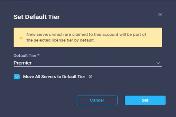
Step 10. Click Refresh to refresh the Intersight window with Premier, Advantage, and Essentials features added.
Step 11. Click ![]() in the Intersight window and click Guided Help > Site Tour. Follow the prompts for a tour of Cisco Intersight.
in the Intersight window and click Guided Help > Site Tour. Follow the prompts for a tour of Cisco Intersight.
Step 12. The Essentials tier of Cisco Intersight includes a Cisco driver check against the Cisco Hardware Compatibility List (HCL). In the Servers list, select one of the servers in your VMware FlexPod-Management cluster by clicking the server name. Review the detailed General and Inventory information for the server. Click the HCL tab. Review the server information, the version of VMware ESXi, and the Cisco VIC driver versions.
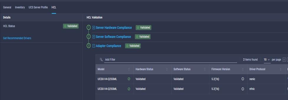
Step 13. Using the Intersight Assist personality of the Cisco Intersight Virtual Appliance, VMware vCenter and NetApp Storage can be monitored (Advantage Licensing Tier) and configured (Premier Licensing Tier). To install Intersight Assist from an Open Virtual Appliance (OVA) in your VMware FlexPod-Management Cluster, first download the latest release of the Cisco Intersight Virtual Appliance for vSphere OVA from https://software.cisco.com/download/home/286319499/type/286323047/release/1.0.9-342.
Refer to: https://www.cisco.com/c/en/us/td/docs/unified_computing/Intersight/b_Cisco_Intersight_Appliance_Getting_Started_Guide/b_Cisco_Intersight_Appliance_Install_and_Upgrade_Guide_chapter_00.html and set up the DNS entries for the Intersight Assist hostname as specified under Before you begin.
Step 14. From Hosts and Clusters in the VMware vCenter HTML5 client, right-click the FlexPod-Management cluster and click Deploy OVF Template.
Step 15. Specify a URL or either browse to the intersight-appliance-installer-vsphere-1.0.9-432.ova or latest release file. Click NEXT.

Step 16. Name the Intersight Assist VM and select the location. Click NEXT.
Step 17. Select the FlexPod-Management cluster and click NEXT.
Step 18. Review details, click Ignore, and click NEXT.
Step 19. Select a deployment configuration (Tiny for just Intersight Assist, Small for Intersight Assist and IWO) and click NEXT.

Step 20. Select infra_datastore01 for storage and select the Thin Provision virtual disk format. Click NEXT.
Step 21. Select IB-MGMT Network for the VM Network. Click NEXT.
Step 22. Fill in all values to customize the template. Click NEXT.
Step 23. Review the deployment information and click FINISH to deploy the appliance.
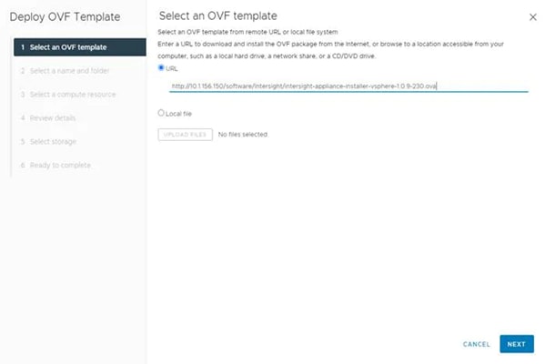
Step 24. Once the OVA deployment is complete, right-click the Intersight Assist VM and click Edit Settings.
Step 25. Expand CPU and adjust the Cores per Socket so that the number of Sockets matches your server CPU configuration. In this example 2 Sockets are shown. Click OK.
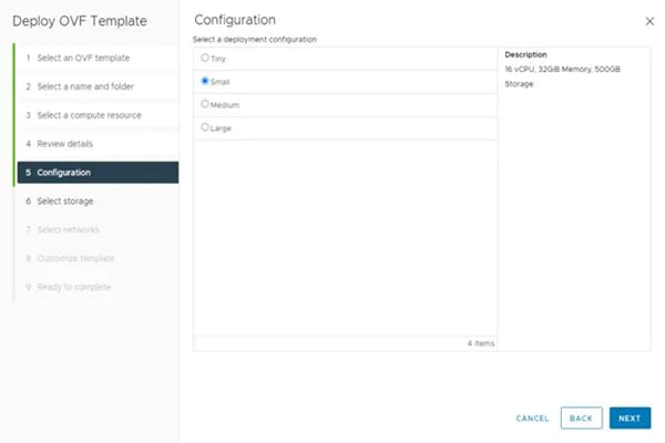
Step 26. Right-click the Intersight Assist VM and select Open Remote Console.
Step 27. Click ![]() to power on the VM.
to power on the VM.
Step 28. When you see the login prompt, close the Remote Console, and connect to https://intersight-assist-fqdn.
Note: It may take a few minutes for https://intersight-assist-fqdn to respond.
Step 29. Navigate the security prompts and select Intersight Assist. Click Proceed.
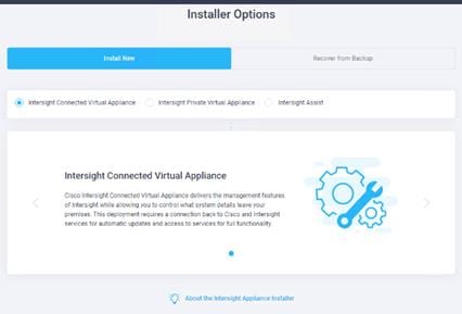
Step 30. From Cisco Intersight, click ADMIN > Targets. Click Claim Target. Select Cisco Intersight Assist and click Start. Click OK on the warning. Copy and paste the Device ID and Claim Code shown in the Intersight Assist web interface to the Cisco Intersight Device Claim Direct Claim window. In Cisco Intersight, click Claim. Intersight Assist will now appear as a claimed device.
Step 31. In the Intersight Assist web interface, verify that Intersight Assist is Connected Successfully, and click Continue.
Note: The Intersight Assist software will now be downloaded and installed into the Intersight Assist VM. This can take up to an hour to complete.
Note: The Intersight Assist VM will reboot during the software download process. It will be necessary to refresh the Web Browser after the reboot is complete to follow the status of the download process.
Step 32. When the software download is complete, an Intersight Assist login screen will appear. Log into Intersight Assist with the admin user and the password supplied in the OVA installation. Check the Intersight Assist status and log out of Intersight Assist.
Procedure 2. Claim vCenter in Intersight
Step 1. To claim the vCenter, from Cisco Intersight, click ADMIN > Targets. Click Claim Target. In the Select Target Type window, select VMware vCenter under Hypervisor and click Start. In the VMware vCenter window, make sure the Intersight Assist is correctly selected, fill in the vCenter information. If Intersight Workflow Optimizer (IWO) will be used, turn on Datastore Browsing Enabled and click Claim.
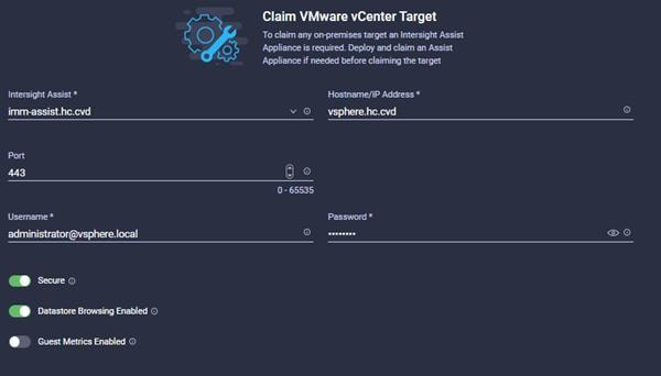
Step 2. After a few minutes, the VMware vCenter will appear in the Devices list. It also can be viewed by clicking Intersight Assist in the Devices list.
Step 3. Detailed information obtained from the vCenter can now be viewed by clicking Virtualization from the menu.
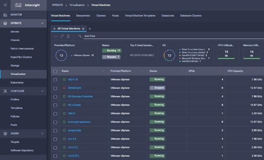
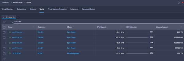
Step 4. If Intersight Premier Licensing is enabled, VMware Virtualization tasks are also defined that can be used to create workflows under Orchestration.
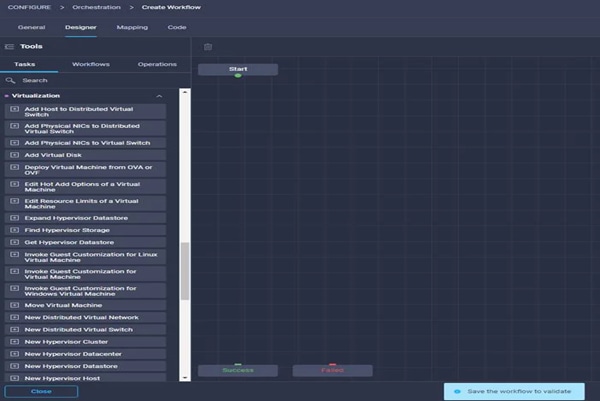
Procedure 3. Claim AIQUM into Cisco Intersight
Step 1. Follow the Pre-Requisites from https://github.com/NetApp-Automation/NetApp-AIQUM
Step 2. Download ansible git: git clone https://github.com/NetApp-Automation/NetApp-AIQUM.git
Step 3. To invoke the ansible scripts use the following command:
ansible-playbook aiqum.yml -t intersight_claim
Step 4. To manually claim the NetApp AIQUM:
a. From Cisco Intersight, click ADMIN > Targets. Click Claim a New Target. In the Select Target Type window, select NetApp Active IQ Unified Manager under Storage and click Start.
b. In the VMware vCenter window, make sure the Intersight Assist is correctly selected, fill in the AIQ UM information, and click Claim.
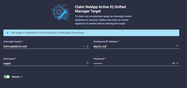
Step 5. After a few minutes, the NetApp ONTAP Storage will appear in the Storage tab. The storage dashboard widgets can also be viewed from Monitoring tab.
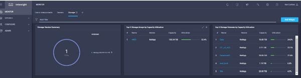
Step 6. Storage and Virtualization tasks and workflows can now be executed from Cisco Intersight Orchestration tab.
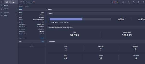
NetApp ONTAP Storage and Virtualization Workflows from Cisco Intersight
Sample Workflow: New NAS Datastore Workflow
This sample workflow creates an NFS storage volume and builds NAS datastores on the volume. It allows you to create an NAS or NFS storage volume by using NetApp storage tasks; then it uses the New NAS Datastore virtualization task to create the NFS datastore on the virtualization hypervisor.
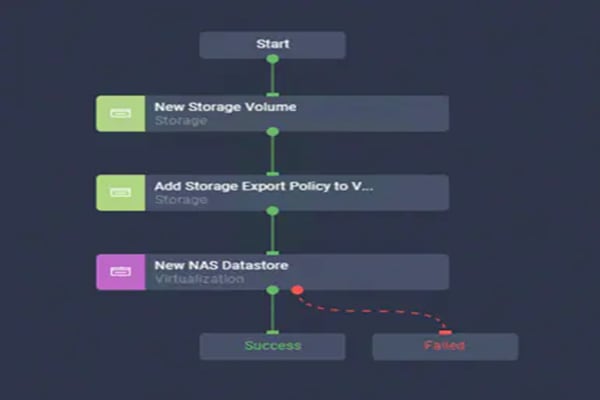
Table 19. Parameters and Values
| Parameter name |
Input value |
| Organization |
default |
| Workflow Instance Name |
New ONTAP NAS Datastore |
| Storage Device* |
aa16-a400 |
| Storage Vendor Virtual Machine* |
Infra_SVM |
| Aggregate* |
aa16_a400_01_NVME_SSD_1 |
| Export Policy* |
default |
| Volume* |
Infra_SVM_NFS_datastore_ICO_01 |
| Volume Capacity* |
100G |
| Mount path* |
/Infra_SVM_NFS_datastore_ICO_01 |
| Hypervisor Manager* |
nx-vc.flexpod.cisco.com |
| Datacenter* |
Epic-DC |
| Cluster |
FlexPod-Management |
| Datastore Name* |
Infra_SVM_NFS_datastore_ICO_01 |
| Datastore Type* |
NFS4.1 |
| Remote Host Names* |
192.168.50.141, 192.168.50.142 |
Sample Workflow: Update VMFS Datastore Workflow
Expand a datastore on hypervisor manager by extending the backing storage volume to specified capacity, and then grow the datastore to utilize the additional capacity. This workflow enables single click execution from Cisco Intersight to execute VMware hypervisor and NetApp ONTAP storage tasks and enable you to expand the VMFS or SAN datastore.
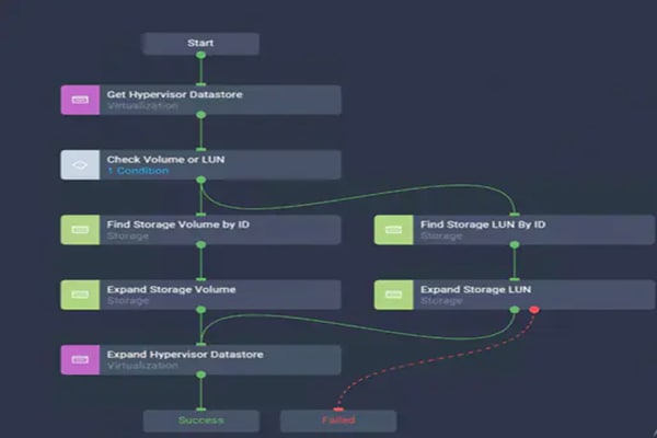
Table 20. Workflow Designer Parameters
| Parameter name |
Input value |
| Organization |
default |
| Workflow Instance Name |
Update ONTAP VMFS Datastore |
| Hypervisor Manager* |
nx-vc.flexpod.cisco.com |
| Datacenter* |
Epic-DC |
| Cluster |
FlexPod-Management |
| Datastore Name* |
Infra_SVM_VMFS_datastore_ICO_01 |
| Storage Device* |
aa16-a400 |
| Datastore Size |
220G |

Custom Workflow: New FC Storage Virtual Machine and Add 4 FC LIFs
This workflow creates a new FC SVM and 4 new Fibre Channel interfaces. Using the NetApp ONTAP Storage tasks create a workflow to create a new SVM and add 4 new Logical Interface tasks for the Fiber Channel Protocol.
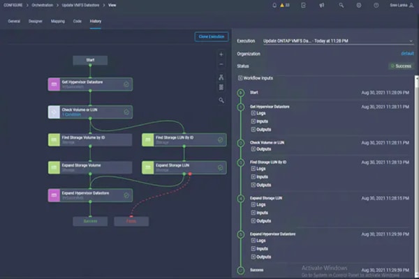
Table 21. Parameters and Values
| Parameter name |
Input value |
| Organization |
default |
| Display Name |
New FC SVM with 4 FC LIFS |
| Storage Device* |
aa16-a400 |
| Storage Vendor Virtual Machine* |
Data_SVM_ICO_01 |
| Storage Vendor Virtual Machine Options |
Storage VM Protocol: |
|
|
FCcol: FC |
| Interface Name |
Data_SVM_FC_LIF_ICO_01 |
| Interface options |
Data Protocol: FCP; |
|
|
Location Port:5a: |
|
|
Location Node Name: aa16-a400-01 |
| Interface Name |
Data_SVM_FC_LIF_ICO_02 |
| Interface options |
Data Protocol: FCP; |
|
|
Location Port:5b: |
|
|
Location Node Name: aa16-a400-01 |
| Interface Name |
Data_SVM_FC_LIF_ICO_03 |
| Interface options |
Data Protocol: FCP; |
|
|
Location Port:5a: |
|
|
Location Node Name: aa16-a400-02 |
| Interface Name |
Data_SVM_FC_LIF_ICO_04 |
| Interface options |
Data Protocol: FCP; |
|
|
Location Port:5b: |
|
|
Location Node Name: aa16-a400-02 |
A high-level summary of the FlexPod Datacenter Design validation is provided in this section. The solution was validated for basic data forwarding by deploying virtual machines running the IOMeter tool. The system was validated for resiliency by failing various aspects of the system under load. Examples of the types of tests executed include:
● Failure and recovery of FC booted ESXi hosts in a cluster
● Rebooting of FC booted hosts
● Service Profile migration between blades
● Failure of partial and complete IOM links
● Failure and recovery of FC paths to AFF nodes, MDS switches, and fabric interconnects
● Storage link failure between one of the AFF nodes and the Cisco MDS
● Load was generated using the GenI/O tool and different IO profiles were used to reflect the different profiles that are seen in customer networks.
As part of the validation effort, solution validation team identifies the problems, works with the appropriate development team to fix the problem, and provides work arounds, as necessary.
GenerationIO Workload
The GenerationIO tool (GenIO) is used to validate this solution. The objective was to run the workload on VM to show IO saturation on the storage along with running the system on a certain latency threshold. A single VM was used to generate the workload by ensuring the CPU cores and RAM were not limiting the IO performance on the storage controllers.
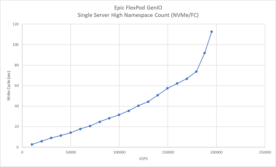
Epic customers as part of their infrastructure upgrade are modernizing the data center using VMware to deploy their entire healthcare applications. The data points showing above is a proof point where customers could deploy their Epic workload along with Clarity, VDI desktops to run multiple workloads on the same infrastructure. The feature rich underlying NetApp system will be able to deliver multi-dimensional performance requirements based on the application needs.
● Initial configuration of Hardware components
● Creation and Deployment of Cisco UCS Templates and Profiles
● Initial configuration of vCenter and ESXi hosts
The FlexPod Datacenter solution is a validated approach for deploying Cisco and NetApp technologies and products for building shared private and public cloud infrastructure. With the introduction of Cisco X-Series modular platform to FlexPod Datacenter, customers can now manage and orchestrate the next-generation Cisco UCS platform from the cloud using Cisco Intersight. Some of the key advantages of integrating Cisco UCS X-Series and Cisco Intersight into the FlexPod infrastructure are:
● Simpler and programmable infrastructure
● Power and cooling innovations and better airflow
● Fabric innovations for heterogeneous compute and memory composability
● Innovative cloud operations providing continuous feature delivery
● Future-ready design built for investment protection
In addition to the Cisco UCS X-Series hardware and software innovations, integration of the Cisco Intersight cloud platform with VMware vCenter and NetApp Active IQ Unified Manager delivers monitoring, orchestration, and workload optimization capabilities for the different layers (including virtualization and storage) of the FlexPod infrastructure. The modular nature of the Cisco Intersight platform also provides an easy upgrade path to additional services, such as workload optimization and Kubernetes.
NetApp was the first all-flash array to get a high-comfort rating from Epic, and it is listed under Enterprise Storage Arrays. Epic requires critical workloads should be separated on storage pools and with Data ONTAP multiple pools of can be provisioned in a single cluster to isolate the workloads.
Ken Corkins, Technical Marketing Engineer, Cisco Systems, Inc.
As a TME in Cisco UCS Solutions group, Ken focuses on network, compute, virtualization, storage, and orchestration of various CI Stacks.
Kamini Singh, Technical Marketing Engineer, Hybrid Cloud Infra & OEM Solutions, NetApp
Kamini has more than two years of experience in data center infrastructure solutions. She focuses on FlexPod hybrid cloud infrastructure solution design, implementation, validation, automation, and sales enablement. Kamini holds a bachelor’s degree in Electronics and Communication and a master’s degree in Communication Systems.
For their support and contribution to the design, validation, and creation of this Cisco Validated Design, the authors would like to thank:
● Jeff Nichols, Technical Marketing Engineer, Cisco Systems, Inc.
● Jon Ebmeier, Technical Solutions Architect, Cisco Systems, Inc.
● Paniraja Koppa, Technical Marketing Engineering, Cisco Systems, Inc.
● Haseeb Niazi, Principal Technical Marketing Engineer, Cisco Systems, Inc.
● John George, Technical Marketing Engineer, Cisco Systems, Inc.
● Bobby Oommen, Technical Lead, FlexPod Solutions, NetApp
This chapter is organized into the following sections:
● Appendix A – References Used in Guide
● Appendix B – Glossary of Acronyms
● Appendix C – Glossary of Terms
Appendix A – References Used in Guide
Cisco Intersight: https://www.intersight.com
Cisco Intersight Managed Mode: https://www.cisco.com/c/en/us/td/docs/unified_computing/Intersight/b_Intersight_Managed_Mode_Configuration_Guide.html
Cisco Unified Computing System: http://www.cisco.com/en/US/products/ps10265/index.html
Cisco UCS 6400 Series Fabric Interconnects: https://www.cisco.com/c/en/us/products/collateral/servers-unified-computing/datasheet-c78-741116.html
Cisco Nexus 9000 Series Switches: http://www.cisco.com/c/en/us/products/switches/nexus-9000-series-switches/index.html
Cisco MDS 9132T Switches: https://www.cisco.com/c/en/us/products/collateral/storage-networking/mds-9100-series-multilayer-fabric-switches/datasheet-c78-739613.html
NetApp ONTAP: https://docs.netapp.com/ontap-9/index.jsp
NetApp Active IQ Unified Manager: https://docs.netapp.com/ocum-98/index.jsp?topic=%2Fcom.netapp.doc.onc-um-isg-lin%2FGUID-FA7D1835-F32A-4A84-BD5A-993F7EE6BBAE.html
ONTAP Storage Connector for Cisco Intersight: https://www.netapp.com/pdf.html?item=/media/25001-tr-4883.pdf
VMware vCenter Server: http://www.vmware.com/products/vcenter-server/overview.html
VMware vSphere: https://www.vmware.com/products/vsphere
Cisco UCS Hardware Compatibility Matrix: https://ucshcltool.cloudapps.cisco.com/public/
VMware and Cisco Unified Computing System: http://www.vmware.com/resources/compatibility
NetApp Interoperability Matrix Tool: http://support.netapp.com/matrix/
Appendix B – Glossary of Acronyms
AAA—Authentication, Authorization, and Accounting
ACP—Access-Control Policy
ACI—Cisco Application Centric Infrastructure
ACK—Acknowledge or Acknowledgement
ACL—Access-Control List
AD—Microsoft Active Directory
AFI—Address Family Identifier
AMP—Cisco Advanced Malware Protection
AP—Access Point
API—Application Programming Interface
APIC— Cisco Application Policy Infrastructure Controller (ACI)
ASA—Cisco Adaptative Security Appliance
ASM—Any-Source Multicast (PIM)
ASR—Aggregation Services Router
Auto-RP—Cisco Automatic Rendezvous Point protocol (multicast)
AVC—Application Visibility and Control
BFD—Bidirectional Forwarding Detection
BGP—Border Gateway Protocol
BMS—Building Management System
BSR—Bootstrap Router (multicast)
BYOD—Bring Your Own Device
CAPWAP—Control and Provisioning of Wireless Access Points Protocol
CDP—Cisco Discovery Protocol
CEF—Cisco Express Forwarding
CMD—Cisco Meta Data
CPU—Central Processing Unit
CSR—Cloud Services Routers
CTA—Cognitive Threat Analytics
CUWN—Cisco Unified Wireless Network
CVD—Cisco Validated Design
CYOD—Choose Your Own Device
DC—Data Center
DHCP—Dynamic Host Configuration Protocol
DM—Dense-Mode (multicast)
DMVPN—Dynamic Multipoint Virtual Private Network
DMZ—Demilitarized Zone (firewall/networking construct)
DNA—Cisco Digital Network Architecture
DNS—Domain Name System
DORA—Discover, Offer, Request, ACK (DHCP Process)
DWDM—Dense Wavelength Division Multiplexing
ECMP—Equal Cost Multi Path
EID—Endpoint Identifier
EIGRP—Enhanced Interior Gateway Routing Protocol
EMI—Electromagnetic Interference
ETR—Egress Tunnel Router (LISP)
EVPN—Ethernet Virtual Private Network (BGP EVPN with VXLAN data plane)
FHR—First-Hop Router (multicast)
FHRP—First-Hop Redundancy Protocol
FMC—Cisco Firepower Management Center
FTD—Cisco Firepower Threat Defense
GBAC—Group-Based Access Control
GbE—Gigabit Ethernet
Gbit/s—Gigabits Per Second (interface/port speed reference)
GRE—Generic Routing Encapsulation
GRT—Global Routing Table
HA—High-Availability
HQ—Headquarters
HSRP—Cisco Hot-Standby Routing Protocol
HTDB—Host-tracking Database (SD-Access control plane node construct)
IBNS—Identity-Based Networking Services (IBNS 2.0 is the current version)
ICMP— Internet Control Message Protocol
IDF—Intermediate Distribution Frame; essentially a wiring closet.
IEEE—Institute of Electrical and Electronics Engineers
IETF—Internet Engineering Task Force
IGP—Interior Gateway Protocol
IID—Instance-ID (LISP)
IOE—Internet of Everything
IoT—Internet of Things
IP—Internet Protocol
IPAM—IP Address Management
IPS—Intrusion Prevention System
IPSec—Internet Protocol Security
ISE—Cisco Identity Services Engine
ISR—Integrated Services Router
IS-IS—Intermediate System to Intermediate System routing protocol
ITR—Ingress Tunnel Router (LISP)
LACP—Link Aggregation Control Protocol
LAG—Link Aggregation Group
LAN—Local Area Network
L2 VNI—Layer 2 Virtual Network Identifier; as used in SD-Access Fabric, a VLAN.
L3 VNI— Layer 3 Virtual Network Identifier; as used in SD-Access Fabric, a VRF.
LHR—Last-Hop Router (multicast)
LISP—Location Identifier Separation Protocol
MAC—Media Access Control Address (OSI Layer 2 Address)
MAN—Metro Area Network
MEC—Multichassis EtherChannel, sometimes referenced as MCEC
MDF—Main Distribution Frame; essentially the central wiring point of the network.
MnT—Monitoring and Troubleshooting Node (Cisco ISE persona)
MOH—Music on Hold
MPLS—Multiprotocol Label Switching
MR—Map-resolver (LISP)
MS—Map-server (LISP)
MSDP—Multicast Source Discovery Protocol (multicast)
MTU—Maximum Transmission Unit
NAC—Network Access Control
NAD—Network Access Device
NAT—Network Address Translation
NBAR—Cisco Network-Based Application Recognition (NBAR2 is the current version).
NFV—Network Functions Virtualization
NSF—Non-Stop Forwarding
OSI—Open Systems Interconnection model
OSPF—Open Shortest Path First routing protocol
OT—Operational Technology
PAgP—Port Aggregation Protocol
PAN—Primary Administration Node (Cisco ISE persona)
PCI DSS—Payment Card Industry Data Security Standard
PD—Powered Devices (PoE)
PETR—Proxy-Egress Tunnel Router (LISP)
PIM—Protocol-Independent Multicast
PITR—Proxy-Ingress Tunnel Router (LISP)
PnP—Plug-n-Play
PoE—Power over Ethernet (Generic term, may also refer to IEEE 802.3af, 15.4W at PSE)
PoE+—Power over Ethernet Plus (IEEE 802.3at, 30W at PSE)
PSE—Power Sourcing Equipment (PoE)
PSN—Policy Service Node (Cisco ISE persona)
pxGrid—Platform Exchange Grid (Cisco ISE persona and publisher/subscriber service)
PxTR—Proxy-Tunnel Router (LISP – device operating as both a PETR and PITR)
QoS—Quality of Service
RADIUS—Remote Authentication Dial-In User Service
REST—Representational State Transfer
RFC—Request for Comments Document (IETF)
RIB—Routing Information Base
RLOC—Routing Locator (LISP)
RP—Rendezvous Point (multicast)
RP—Redundancy Port (WLC)
RP—Route Processer
RPF—Reverse Path Forwarding
RR—Route Reflector (BGP)
RTT—Round-Trip Time
SA—Source Active (multicast)
SAFI—Subsequent Address Family Identifiers (BGP)
SD—Software-Defined
SDA—Cisco Software Defined-Access
SDN—Software-Defined Networking
SFP—Small Form-Factor Pluggable (1 GbE transceiver)
SFP+— Small Form-Factor Pluggable (10 GbE transceiver)
SGACL—Security-Group ACL
SGT—Scalable Group Tag, sometimes reference as Security Group Tag
SM—Spare-mode (multicast)
SNMP—Simple Network Management Protocol
SSID—Service Set Identifier (wireless)
SSM—Source-Specific Multicast (PIM)
SSO—Stateful Switchover
STP—Spanning-tree protocol
SVI—Switched Virtual Interface
SVL—Cisco StackWise Virtual
SWIM—Software Image Management
SXP—Scalable Group Tag Exchange Protocol
Syslog—System Logging Protocol
TACACS+—Terminal Access Controller Access-Control System Plus
TCP—Transmission Control Protocol (OSI Layer 4)
UCS— Cisco Unified Computing System
UDP—User Datagram Protocol (OSI Layer 4)
UPoE—Cisco Universal Power Over Ethernet (60W at PSE)
UPoE+— Cisco Universal Power Over Ethernet Plus (90W at PSE)
URL—Uniform Resource Locator
VLAN—Virtual Local Area Network
VM—Virtual Machine
VN—Virtual Network, analogous to a VRF in SD-Access
VNI—Virtual Network Identifier (VXLAN)
vPC—virtual Port Channel (Cisco Nexus)
VPLS—Virtual Private LAN Service
VPN—Virtual Private Network
VPNv4—BGP address family that consists of a Route-Distinguisher (RD) prepended to an IPv4 prefix
VPWS—Virtual Private Wire Service
VRF—Virtual Routing and Forwarding
VSL—Virtual Switch Link (Cisco VSS component)
VSS—Cisco Virtual Switching System
VXLAN—Virtual Extensible LAN
WAN—Wide-Area Network
WLAN—Wireless Local Area Network (generally synonymous with IEEE 802.11-based networks)
WoL—Wake-on-LAN
xTR—Tunnel Router (LISP – device operating as both an ETR and ITR)
Appendix C – Glossary of Terms
This glossary addresses some terms used in this document, for the purposes of aiding understanding. This is not a complete list of all multicloud terminology. Some Cisco product links are supplied here also, where considered useful for the purposes of clarity, but this is by no means intended to be a complete list of all applicable Cisco products.
| aaS/XaaS (IT capability provided as a Service) |
Some IT capability, X, provided as a service (XaaS). Some benefits are:
● The provider manages the design, implementation, deployment, upgrades, resiliency, scalability, and overall delivery of the service and the infrastructure that supports it.
● There are very low barriers to entry, so that services can be quickly adopted and dropped in response to business demand, without the penalty of inefficiently utilized CapEx.
● The service charge is an IT OpEx cost (pay-as-you-go), whereas the CapEx and the service infrastructure is the responsibility of the provider.
● Costs are commensurate to usage and hence more easily controlled with respect to business demand and outcomes.
Such services are typically implemented as “microservices,” which are accessed via REST APIs. This architectural style supports composition of service components into systems. Access to and management of aaS assets is via a web GUI and/or APIs, such that Infrastructure-as-code (IaC) techniques can be used for automation, for example, Ansible and Terraform. The provider can be any entity capable of implementing an aaS “cloud-native” architecture. The cloud-native architecture concept is well-documented and supported by open-source software and a rich ecosystem of services such as training and consultancy. The provider can be an internal IT department or any of many third-party companies using and supporting the same open-source platforms. Service access control, integrated with corporate IAM, can be mapped to specific users and business activities, enabling consistent policy controls across services, wherever they are delivered from. |
| Ansible |
An infrastructure automation tool, used to implement processes for instantiating and configuring IT service components, such as VMs on an IaaS platform. Supports the consistent execution of processes defined in YAML “playbooks” at scale, across multiple targets. Because the Ansible artefacts (playbooks) are text-based, they can be stored in a Source Code Management (SCM) system, such as GitHub. This allows for software development like processes to be applied to infrastructure automation, such as, Infrastructure-as-code (see IaC below). |
| AWS (Amazon Web Services) |
Provider of IaaS and PaaS. |
| Azure |
Microsoft IaaS and PaaS. |
| Co-located data center |
“A colocation center (CoLo)…is a type of data center where equipment, space, and bandwidth are available for rental to retail customers. Colocation facilities provide space, power, cooling, and physical security for the server, storage, and networking equipment of other firms and also connect them to a variety of telecommunications and network service providers with a minimum of cost and complexity.” |
| Containers (Docker) |
A (Docker) container is a means to create a package of code for an application and its dependencies, such that the application can run on different platforms which support the Docker environment. In the context of aaS, microservices are typically packaged within Linux containers orchestrated by Kubernetes (K8s). https://www.cisco.com/c/en/us/products/cloud-systems-management/containerplatform/index.html |
| DevOps |
The underlying principle of DevOps is that the application development and operations teams should work closely together, ideally within the context of a toolchain that automates the stages of development, test, deployment, monitoring, and issue handling. DevOps is closely aligned with IaC, continuous integration and deployment (CI/CD), and Agile software development practices. |
| Edge compute |
Edge compute is the idea that it can be more efficient to process data at the edge of a network, close to the endpoints that originate that data, or to provide virtualized access services, such as at the network edge. This could be for reasons related to low latency response, reduction of the amount of unprocessed data being transported, efficiency of resource utilization, and so on. The generic label for this is Multi-access Edge Computing (MEC), or Mobile Edge Computing for mobile networks specifically. From an application experience perspective, it is important to be able to utilize, at the edge, the same operations model, processes, and tools used for any other compute node in the system. |
| IaaS (Infrastructure as-a-Service) |
Infrastructure components provided aaS, located in data centers operated by a provider, typically accessed over the public Internet. IaaS provides a base platform for the deployment of workloads, typically with containers and Kubernetes (K8s). |
| IaC (Infrastructure as-Code) |
Given the ability to automate aaS via APIs, the implementation of the automation is typically via Python code, Ansible playbooks, and similar. These automation artefacts are programming code that define how the services are consumed. As such, they can be subject to the same code management and software development regimes as any other body of code. This means that infrastructure automation can be subject to all of the quality and consistency benefits, CI/CD, traceability, automated testing, compliance checking, and so on, that could be applied to any coding project. |
| IAM (Identity and Access Management) |
IAM is the means to control access to IT resources so that only those explicitly authorized to access given resources can do so. IAM is an essential foundation to a secure multicloud environment. |
| IBM (Cloud) |
IBM IaaS and PaaS. |
| Intersight |
Cisco Intersight™ is a Software-as-a-Service (SaaS) infrastructure lifecycle management platform that delivers simplified configuration, deployment, maintenance, and support. https://www.cisco.com/c/en/us/products/servers-unified-computing/intersight/index.html |
| GCP (Google Cloud Platform) |
Google IaaS and PaaS. |
| Kubernetes (K8s) |
Kubernetes is an open-source system for automating deployment, scaling, and management of containerized applications. |
| Microservices |
A microservices architecture is characterized by processes implementing fine-grained services, typically exposed via REST APIs and which can be composed into systems. The processes are often container-based, and the instantiation of the services often managed with Kubernetes. Microservices managed in this way are intrinsically well suited for deployment into IaaS environments, and as such, are the basis of a cloud native architecture. |
| PaaS (Platform-as-a-Service) |
PaaS is a layer of value-add services, typically for application development, deployment, monitoring, and general lifecycle management. The use of IaC with IaaS and PaaS is very closely associated with DevOps practices. |
| Private on-premises data center |
A data center infrastructure housed within an environment owned by a given enterprise is distinguished from other forms of data center, with the implication that the private data center is more secure, given that access is restricted to those authorized by the enterprise. Thus, circumstances can arise where very sensitive IT assets are only deployed in a private data center, in contrast to using public IaaS. For many intents and purposes, the underlying technology can be identical, allowing for hybrid deployments where some IT assets are privately deployed but also accessible to other assets in public IaaS. IAM, VPNs, firewalls, and similar are key technologies needed to underpin the security of such an arrangement. |
| REST API |
Representational State Transfer (REST) APIs is a generic term for APIs accessed over HTTP(S), typically transporting data encoded in JSON or XML. REST APIs have the advantage that they support distributed systems, communicating over HTTP, which is a well-understood protocol from a security management perspective. REST APIs are another element of a cloud-native applications architecture, alongside microservices. https://en.wikipedia.org/wiki/Representational_state_transfer |
| SaaS (Software-as-a-Service) |
End-user applications provided “aaS” over the public Internet, with the underlying software systems and infrastructure owned and managed by the provider. |
| SAML (Security Assertion Markup Language) |
Used in the context of Single-Sign-On (SSO) for exchanging authentication and authorization data between an identity provider, typically an IAM system, and a service provider (some form of SaaS). The SAML protocol exchanges XML documents that contain security assertions used by the aaS for access control decisions. https://en.wikipedia.org/wiki/Security_Assertion_Markup_Language |
| Terraform |
An open-source IaC software tool for cloud services, based on declarative configuration files. |
For comments and suggestions about this guide and related guides, join the discussion on Cisco Community at https://cs.co/en-cvds.
CVD Program
ALL DESIGNS, SPECIFICATIONS, STATEMENTS, INFORMATION, AND RECOMMENDATIONS (COLLECTIVELY, "DE-SIGNS") IN THIS MANUAL ARE PRESENTED "AS IS," WITH ALL FAULTS. CISCO AND ITS SUPPLIERS DISCLAIM ALL WAR-RANTIES, INCLUDING, WITHOUT LIMITATION, THE WARRANTY OF MERCHANTABILITY, FITNESS FOR A PARTICULAR PURPOSE AND NONINFRINGEMENT OR ARISING FROM A COURSE OF DEALING, USAGE, OR TRADE PRACTICE. IN NO EVENT SHALL CISCO OR ITS SUPPLIERS BE LIABLE FOR ANY INDIRECT, SPECIAL, CONSEQUENTIAL, OR INCIDENTAL DAMAGES, INCLUDING, WITHOUT LIMITATION, LOST PROFITS OR LOSS OR DAMAGE TO DATA ARISING OUT OF THE USE OR INABILITY TO USE THE DESIGNS, EVEN IF CISCO OR ITS SUPPLIERS HAVE BEEN ADVISED OF THE POSSIBILITY OF SUCH DAMAGES.
THE DESIGNS ARE SUBJECT TO CHANGE WITHOUT NOTICE. USERS ARE SOLELY RESPONSIBLE FOR THEIR APPLICA-TION OF THE DESIGNS. THE DESIGNS DO NOT CONSTITUTE THE TECHNICAL OR OTHER PROFESSIONAL ADVICE OF CISCO, ITS SUPPLIERS OR PARTNERS. USERS SHOULD CONSULT THEIR OWN TECHNICAL ADVISORS BEFORE IMPLE-MENTING THE DESIGNS. RESULTS MAY VARY DEPENDING ON FACTORS NOT TESTED BY CISCO.
CCDE, CCENT, Cisco Eos, Cisco Lumin, Cisco Nexus, Cisco StadiumVision, Cisco TelePresence, Cisco WebEx, the Cisco logo, DCE, and Welcome to the Human Network are trademarks; Changing the Way We Work, Live, Play, and Learn and Cisco Store are service marks; and Access Registrar, Aironet, AsyncOS, Bringing the Meeting To You, Catalyst, CCDA, CCDP, CCIE, CCIP, CCNA, CCNP, CCSP, CCVP, Cisco, the Cisco Certified Internetwork Expert logo, Cisco IOS, Cisco Press, Cisco Systems, Cisco Systems Capital, the Cisco Systems logo, Cisco Unified Computing System (Cisco UCS), Cisco UCS B-Series Blade Servers, Cisco UCS C-Series Rack Servers, Cisco UCS S-Series Storage Servers, Cisco UCS Manager, Cisco UCS Management Software, Cisco Unified Fabric, Cisco Application Centric Infrastructure, Cisco Nexus 9000 Series, Cisco Nexus 7000 Series. Cisco Prime Data Center Network Manager, Cisco NX-OS Software, Cis-co MDS Series, Cisco Unity, Collaboration Without Limitation, EtherFast, EtherSwitch, Event Center, Fast Step, Follow Me Browsing, FormShare, GigaDrive, HomeLink, Internet Quotient, IOS, iPhone, iQuick Study, LightStream, Linksys, MediaTone, MeetingPlace, MeetingPlace Chime Sound, MGX, Networkers, Networking Academy, Network Registrar, PCNow, PIX, PowerPanels, ProConnect, ScriptShare, SenderBase, SMARTnet, Spectrum Expert, StackWise, The Fastest Way to Increase Your Internet Quotient, TransPath, WebEx, and the WebEx logo are registered trade-marks of Cisco Systems, Inc. and/or its affiliates in the United States and certain other countries. (LDW_U1)
All other trademarks mentioned in this document or website are the property of their respective owners. The use of the word partner does not imply a partnership relationship between Cisco and any other company. (0809R)