FlexPod Datacenter for Microsoft SQL Server 2022 and VMware vSphere 8.0
Available Languages
Bias-Free Language
The documentation set for this product strives to use bias-free language. For the purposes of this documentation set, bias-free is defined as language that does not imply discrimination based on age, disability, gender, racial identity, ethnic identity, sexual orientation, socioeconomic status, and intersectionality. Exceptions may be present in the documentation due to language that is hardcoded in the user interfaces of the product software, language used based on RFP documentation, or language that is used by a referenced third-party product. Learn more about how Cisco is using Inclusive Language.
- US/Canada 800-553-2447
- Worldwide Support Phone Numbers
- All Tools
 Feedback
 Feedback
![]()
In partnership with:

About the Cisco Validated Design Program
The Cisco Validated Design (CVD) program consists of systems and solutions designed, tested, and documented to facilitate faster, more reliable, and more predictable customer deployments. For more information, go to: http://www.cisco.com/go/designzone.
It is important that a datacenter solution embrace technology advancement in various areas, such as compute, network, and storage technologies to address rapidly changing requirements and challenges of IT organizations. The current industry trend in datacenter design is towards shared infrastructures. By using virtualization along with pre-validated IT platforms, enterprise customers have embarked on the journey to the cloud by moving away from application silos and toward shared infrastructure that can be quickly deployed, thereby increasing agility, and reducing costs. Cisco and NetApp have partnered to deliver FlexPod, which uses best of breed storage, server, and network components to serve as the foundation for a variety of workloads, enabling efficient architectural designs that can be quickly and confidently deployed.
This document describes a FlexPod reference architecture using the latest hardware and software products and provides design and deployment recommendations for hosting Microsoft SQL Server 2022 databases in VMware ESXi virtualized environments.
This Cisco Validated Document (CVD) describes the reference FlexPod Datacenter architecture using Cisco UCS X-Series compute and NetApp All Flash FAS (AFF) Storage for deploying highly available Microsoft SQL Server databases on VMware ESXi virtualized environments. The document provides hardware and software configurations of the components involved, results of various performance tests, backup to cloud use case using NetApp SnapMirror technology for Disaster Recovery (DR) of the databases, backup, restore, and cloning of SQL databases using NetApp SnapCenter, and also discusses implementation best practices guidance for deploying the solution.
This chapter contains the following:
● Audience
The current IT industry is witnessing vast transformations in the datacenter solutions. In the recent years, there is a considerable interest towards pre-validated and engineered datacenter solutions. Introduction of virtualization technology in the key areas has impacted the design principles and architectures of these solutions in a big way. It has opened the doors for many applications running on bare metal systems to migrate to these new virtualized integrated solutions.
FlexPod System is one such pre-validated and engineered datacenter solution designed to address rapidly changing needs of IT organizations. Cisco and NetApp have partnered to deliver FlexPod, which uses best of breed compute, network, and storage components to serve as the foundation for a variety of enterprise workloads including databases, ERP, CRM, and Web applications, and so on.
The consolidation of IT applications, particularly databases, has generated considerable interest in the recent years. Being most widely adopted and deployed database platform over several years, Microsoft SQL Server databases have become the victim of a popularly known IT challenge “Database Sprawl.” Some of the challenges of SQL Server sprawl include underutilized Servers, high licensing costs, security concerns, management concerns, huge operational costs and so on. Therefore SQL Server databases would be right candidate for migrating and consolidating on to a more robust, flexible, and resilient platform. This document discusses a FlexPod reference architecture for deploying and consolidating SQL Server databases.
The intended audience for this document includes, but is not limited to, sales engineers, field consultants, database administrators, professional services, IT managers, partner engineers, and customers who want to take advantage of an infrastructure built to deliver IT efficiency and enable IT innovation. It is expected that the reader should have prior knowledge on FlexPod Systems and its components.
This document describes a FlexPod reference architecture and step-by-step implementation guidelines for deploying Microsoft SQL Server 2022 databases on FlexPod system.
The following software and hardware products distinguish the reference architecture from previous releases:
● Microsoft SQL Server 2022 deployment on Windows Server 2022 Guest VMs running on VMWare vSphere 8.0 Cluster.
● Tested and validated using Cisco UCS X-Series X210c M7 compute nodes powered by Intel 4th Generation Intel Xeon Scalable processors, Cisco UCS 5th Generation Fabric Interconnects, Cisco Nexus 9000 Series Switches enabling end-to-end 100 Gbps connectivity.
● NetApp All Flash FAS (AFF) A400 storage with ONTAP 9.12.1 with a set of enterprise grade storage platform features.
● Performance and price benefits of migrating SQL Server databases from Cisco UCS B200 M5 Blade Servers (built with intel 2nd Generation processors) to the latest FlexPod Systems built with Cisco UCS X210c M7 compute nodes (built with intel 4th Generation processors).
● NetApp Cloud Volumes ONTAP (CVO) for backup and Disaster Recovery (DR) of SQL databases.
● NetApp BlueXP for hybrid multicloud experience of storage and data services across on-prem and cloud environments.
● NetApp Snapcenter 4.8 for Virtual Machine Operating System level backup and recovery.
● NetApp Snapcenter 4.8 for SQL Server database backup, recovery, protection, and cloning.
● NetApp SnapCenter 4.8 for storage provisioning to Windows VMs for SQL Database and Log files.
● NetApp ONTAP tools for provisioning datastores to VMware ESXi hosts.
● Direct storage connectivity for SQL Server virtual machines for storing database files using in-Guest software iSCSI initiator.
● Cisco Intersight Software as a Service (SaaS) for the UCS infrastructure lifecycle management and NetApp ONTAP monitoring and other management tasks.
The FlexPod Datacenter solution with Cisco UCS M7, VMware 8.0, and NetApp ONTAP 9.12.1 offers the following key benefits:
● Simplified cloud-based management of solution components
● Hybrid-cloud-ready, policy-driven modular design
● Highly available and scalable platform with flexible architecture that supports various deployment models
● Cooperative support model and Cisco Solution Support
● Easy to deploy, consume, and manage architecture, which saves time and resources required to research, procure, and integrate off-the-shelf components
● Support for component monitoring, solution automation and orchestration, and workload optimization
Like all other FlexPod solution designs, FlexPod Datacenter with Cisco USC M7 is configurable according to demand and usage. You can purchase exactly the infrastructure you need for your current application requirements and can then scale-up by adding more resources to the FlexPod system or scale-out by adding more FlexPod instances. By moving the management from the fabric interconnects into the cloud, the solution can respond to the speed and scale of your deployments with a constant stream of new capabilities delivered from Intersight software-as-a-service model at cloud-scale. If you require management within the secure site, Cisco Intersight is also offered within an on-site appliance with both connected and not connected or air gap options.
This chapter contains the following:
● Cisco Unified Computing System X-Series
● Cisco UCS 6536 Fabric Interconnects
● Cisco Nexus Switching Fabric
● NetApp ASA (All-flash SAN Array)
● NetApp ONTAP Tools for VMware vSphere
● NetApp Active IQ Unified Manager
● NetApp Cloud Volumes ONTAP (CVO)
● Microsoft Windows Server 2022
FlexPod is a best practice datacenter infrastructure architecture that includes these components:
● Cisco Unified Computing System (Cisco UCS)
● Cisco Nexus and MDS Switches
● NetApp All Flash FAS (AFF), FAS, and All SAN Array (ASA) Storage systems
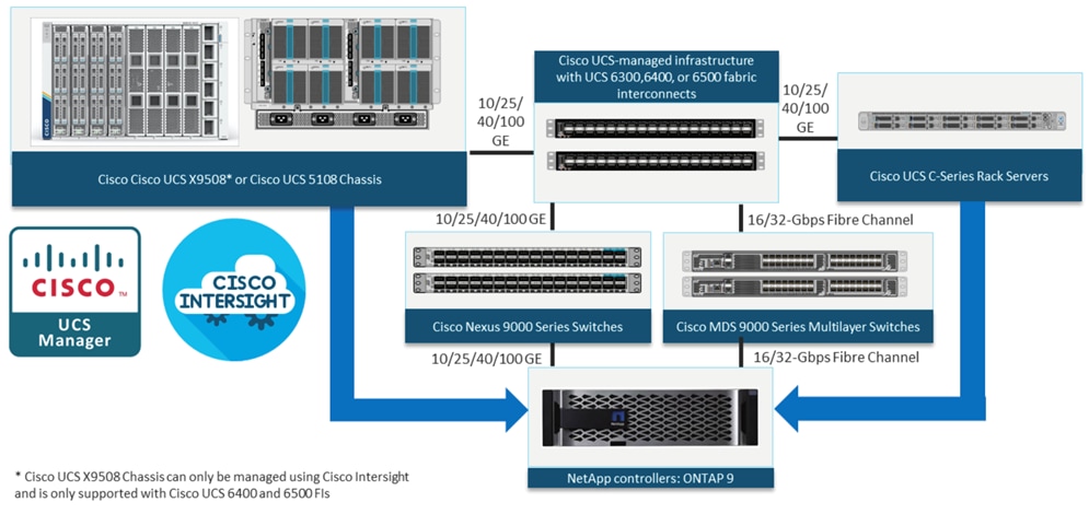
These components are connected and configured according to the best practices of Cisco and NetApp and provide an excellent platform for running multiple enterprise workloads with confidence. The reference architecture explained in this document uses Cisco Nexus 9000 Series Switches. One of the main benefits of FlexPod is the capability to maintain consistency at scale, including scale-up and scale-out deployments. Each of the component families shown in Figure 1 (Cisco UCS, Cisco Nexus, and NetApp storage systems) offers platform and resource options to scale the infrastructure up or down, while supporting the features and functions that are required under the configuration and connectivity best practices for FlexPod.
The FlexPod Datacenter solution covered in this CVD is built and validated using these components:
● Cisco UCS X9508 Chassis with Cisco UCSX-I-9108-100G Intelligent Fabric Modules and up to eight Cisco UCS X210c M7 compute nodes.
● Fifth-generation Cisco UCS 6536 Fabric Interconnects to support 10/25/40/100GbE and 16/32GbFC connectivity from various components.
● High-speed Cisco NX-OS-based Cisco Nexus 93360YC-FX2 switching design to support up to 100GE connectivity.
● NetApp AFF A400 storage array with up to 100GE connectivity over NFS and iSCSI protocols.
The software components of the solutions consist of:
● Cisco Intersight platform to deploy the Cisco UCS components and maintain and support the FlexPod components.
● Cisco Intersight Assist Virtual Appliance to help connect NetApp AIQUM, Cisco Nexus Switches, and VMware vCenter to Cisco Intersight.
● NetApp Cloud Volumes ONTAP (CVO) for protecting the on-prem SQL Server databases using NetApp SnapMirror.
● NetApp BlueXP for managing both on-premises ONTAP and CVO storage systems.
● NetApp SnapCenter for protecting Microsoft SQL Server databases.
● NetApp Active IQ Unified Manager to monitor and manage the storage and for NetApp ONTAP integration with Cisco Intersight.
● VMware vCenter to set up and manage the virtual infrastructure as well as Cisco Intersight integration.
As customers transition to shared infrastructure or cloud computing, they face challenges related to initial transition glitches, return on investment (ROI) analysis, infrastructure management, future growth plans, and other factors. By introducing standardization, FlexPod helps customers mitigate the risk and uncertainty involved in planning, designing, and implementing a new datacenter infrastructure. The result is a more predictive and adaptable architecture capable of meeting and exceeding customers' IT demands.
The following list summarizes the unique features and benefits that the FlexPod system provides for consolidating SQL Server database deployments:
● Support for 4th Generation Intel Xeon Scalable family CPUs, Cisco UCS X-Series X210c M7 compute nodes enables consolidation of more SQL Server virtual machines, and thereby achieving higher consolidation ratios and reducing total cost of ownership (TCO) and achieving quick ROI. Also, Intel 4th Generation Xeon based processors deliver customers a range of features for managing power and performance making optimal use of CPU resources to help achieve their sustainability goals.
● 100 Gigabit Ethernet connectivity and storage connectivity using Cisco UCS 5th Generation fabric interconnects, Cisco Nexus 9000 Series Switches, and NetApp AFF A400 storage arrays.
● Nondisruptive policy-based management of infrastructure using Cisco UCS in Intersight Managed Mode (IMM).
● Fast I/O performance using NetApp All Flash FAS storage arrays and complete virtual machine protection by using NetApp Snapshot technology and direct storage access to SQL Server virtual machines using the in-guest iSCSI initiator.
● NetApp SnapCenter provides application-consistent backups and the ability to quickly restore or clone databases for SQL server deployments.
● NetApp CVO for disaster recovery of on-premises SQL workloads.
Cisco Unified Computing System X-Series
The Cisco UCS X-Series Modular System is designed to take the current generation of the Cisco UCS platform to the next level with its future-ready design and cloud-based management. Decoupling and moving the platform management to the cloud allows Cisco UCS to respond to your feature and scalability requirements in a much faster and efficient manner. Cisco UCS X-Series state of the art hardware simplifies the data-center design by providing flexible server options. A single server type, supporting a broader range of workloads, results in fewer different data center products to manage and maintain. The Cisco Intersight cloud-management platform manages Cisco UCS X-Series as well as integrating with third-party devices, including VMware vCenter and NetApp storage, to provide visibility, optimization, and orchestration from a single platform, thereby driving agility and deployment consistency.
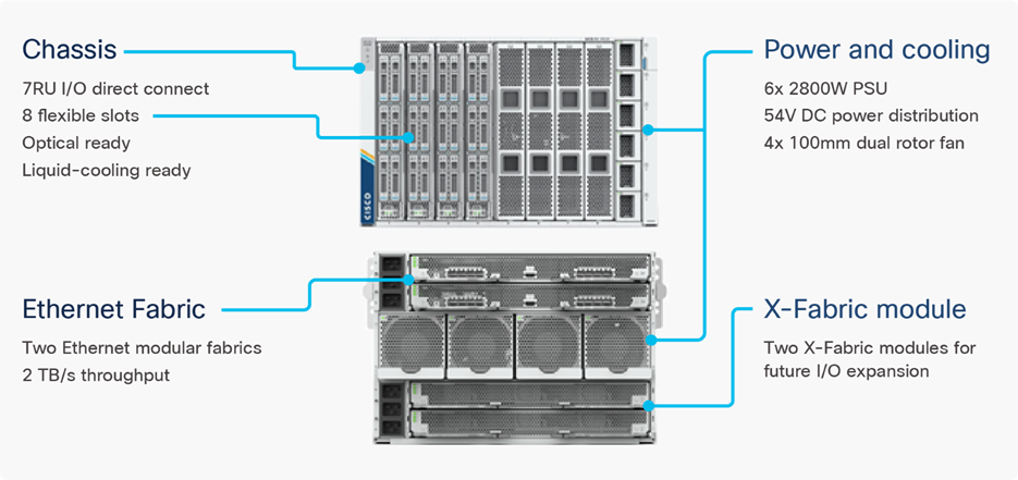
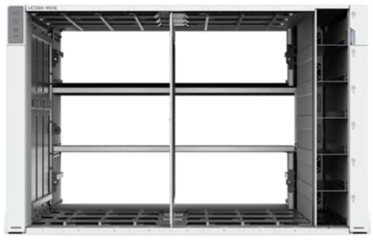
Cisco UCS X9508 Chassis
The Cisco UCS X-Series chassis is engineered to be adaptable and flexible. As seen in Figure 3, the Cisco UCS X9508 chassis has only a power-distribution midplane. This midplane-free design provides fewer obstructions for better airflow. For I/O connectivity, vertically oriented compute nodes intersect with horizontally oriented fabric modules, allowing the chassis to support future fabric innovations. Cisco UCS X9508 Chassis’ superior packaging enables larger compute nodes, thereby providing more space for actual compute components, such as memory, GPU, drives, and accelerators. Improved airflow through the chassis enables support for higher power components, and more space allows for future thermal solutions (such as liquid cooling) without limitations.
Cisco UCSX-I-9508-100G Intelligent Fabric Modules
In the end-to-end 100Gbps Ethernet design, for the Cisco UCS X9508 Chassis, the network connectivity is provided by a pair of Cisco UCSX-I-9108-100G Intelligent Fabric Modules (IFMs). Like the fabric extenders used in the Cisco UCS 5108 Blade Server Chassis, these modules carry all network traffic to a pair of Cisco UCS 6536 Fabric Interconnects (FIs). IFMs also host the Chassis Management Controller (CMC) for chassis management. In contrast to systems with fixed networking components, Cisco UCS X9508’s midplane-free design enables easy upgrades to new networking technologies as they emerge making it straightforward to accommodate new network speeds or technologies in the future.
Each IFM supports eight 100Gb uplink ports for connecting the Cisco UCS X9508 Chassis to the FIs and 8 100Gb or 32 25Gb server ports for the eight compute nodes. IFM server ports can provide up to 200 Gbps of unified fabric connectivity per compute node across the two IFMs. The uplink ports connect the chassis to the Cisco UCS FIs, providing up to 1600Gbps connectivity across the two IFMs. The unified fabric carries management, VM, and Fibre Channel over Ethernet (FCoE) traffic to the FIs, where server management traffic is routed to the Cisco Intersight cloud operations platform, FCoE traffic is forwarded to either native Fibre Channel interfaces through unified ports on the FI (to Cisco MDS switches) or to FCoE uplinks (to Cisco Nexus switches supporting SAN switching), and data Ethernet traffic is forwarded upstream to the data center network (using Cisco Nexus switches).
Cisco UCS X210c M7 Compute Node
The Cisco UCS X9508 Chassis is designed to host up to 8 Cisco UCS X210c M7 or X210c M6 Compute Nodes. The hardware details of the Cisco UCS X210c M7 Compute Nodes are shown in Figure 5.
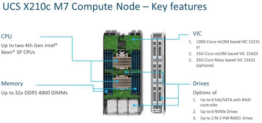
The Cisco UCS X210c M7 features:
● CPU: Up to 2x 4th Gen Intel Xeon Scalable Processors with up to 60 cores per processor and 2.625 MB Level 3 cache per core and up to 112.5 MB per CPU.
● Memory: Up to 32 x 256 GB DDR5-4800 DIMMs for a maximum of 8 TB of main memory.
● Disk storage: Up to 6 SAS or SATA drives or NVMe drives can be configured with the choice of an internal RAID controller or passthrough controllers. Two M.2 memory cards can be added to the Compute Node with optional hardware RAID.
● GPUs: The optional front mezzanine GPU module allows support for up to two HHHL GPUs. Adding a mezzanine card and a Cisco UCS X440p PCIe Node allows up to four more GPUs to be supported with a Cisco UCS X210c M7.
● Virtual Interface Card (VIC): Up to 2 VICs including an mLOM Cisco UCS VIC 15231 or an mLOM Cisco UCS VIC 15420 and a mezzanine Cisco UCS VIC card 15422 can be installed in a Compute Node.
● Security: The server supports an optional Trusted Platform Module (TPM). Additional security features include a secure boot FPGA and ACT2 anticounterfeit provisions.
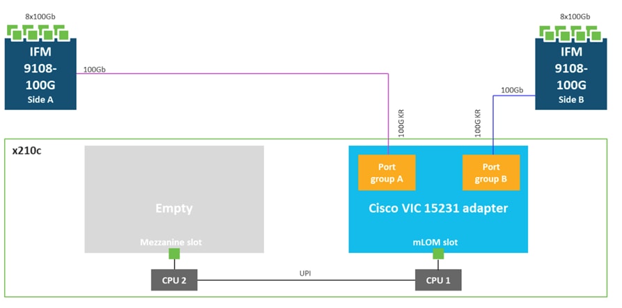
Cisco UCS Virtual Interface Card 15231 (VICs)
Cisco UCS X210c M7 Compute Nodes support multiple Cisco UCS VIC cards. In this solution, Cisco UCS VIC 15231 is used for the validation.
Cisco UCS VIC 15231 fits the mLOM slot in the Cisco UCS X210c Compute Node and enables up to 100 Gbps of unified fabric connectivity to each of the chassis IFMs for a total of 200 Gbps of connectivity per server. Cisco UCS VIC 15231 connectivity to the IFM and up to the fabric interconnects is delivered through 100Gbps. Cisco UCS VIC 15231 supports 512 virtual interfaces (both FCoE and Ethernet) along with the latest networking innovations such as NVMeoF over FC or TCP, VxLAN/NVGRE offload, and so forth.
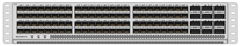
Cisco UCS 6536 Fabric Interconnects
The Cisco UCS Fabric Interconnects (FIs) provide a single point for connectivity and management for the entire Cisco Unified Computing System. Typically deployed as an active/active pair, the system’s FIs integrate all components into a single, highly available management domain controlled by Cisco Intersight. Cisco UCS FIs provide a single unified fabric for the system, with low-latency, lossless, cut-through switching that supports LAN, SAN, and management traffic using a single set of cables.

The Cisco UCS 6536 utilized in the current design is a 36-port Fabric Interconnect. This single RU device includes up to 36 10/25/40/100 Gbps Ethernet ports, 16 8/16/32-Gbps Fibre Channel ports via 4 128 Gbps to 4x32 Gbps breakouts on ports 33-36. All 36 ports support breakout cables or QSA interfaces.
The Cisco Intersight platform is a Software-as-a-Service (SaaS) infrastructure lifecycle management platform that delivers simplified configuration, deployment, maintenance, and support. The Cisco Intersight platform is designed to be modular, so you can adopt services based on your individual requirements. The platform significantly simplifies IT operations by bridging applications with infrastructure, providing visibility and management from bare-metal servers and hypervisors to serverless applications, thereby reducing costs and mitigating risk. This unified SaaS platform uses a unified Open API design that natively integrates with third-party platforms and tools.
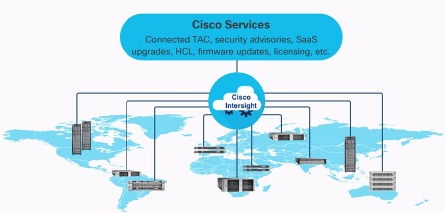
The main advantages of the Cisco Intersight infrastructure services are as follows:
● Simplify daily operations by automating many daily manual tasks.
● Combine the convenience of a SaaS platform with the capability to connect from anywhere and manage infrastructure through a browser or mobile application.
● Stay ahead of problems and accelerate trouble resolution through advanced support capabilities.
● Gain global visibility of infrastructure health and status along with advanced management and support capabilities.
● Upgrade to add workload optimization and other services when needed.
Cisco Intersight Assist
Cisco Intersight Assist helps you add endpoint devices to Cisco Intersight. A data center could have multiple devices that do not connect directly with Cisco Intersight. Any device that is supported by Cisco Intersight, but does not connect directly with it, will need a connection mechanism. Cisco Intersight Assist provides that connection mechanism. In FlexPod, VMware vCenter, NetApp Active IQ Unified Manager, Cisco Nexus Switches, and Cisco MDS switches connect to Intersight with the help of the Intersight Assist VM.
Cisco Intersight Assist is available within the Cisco Intersight Virtual Appliance, which is distributed as a deployable virtual machine contained within an Open Virtual Appliance (OVA) file format. More details about the Cisco Intersight Assist VM deployment configuration is explained in later sections.
Licensing Requirements
The Cisco Intersight platform uses a new subscription-based license model now with two tiers. You can purchase a subscription duration of one, three, or five years and choose the required Cisco UCS server volume tier for the selected subscription duration. For Cisco UCS M6 and below servers, each Cisco endpoint can be claimed into Intersight at no additional cost (no license) and can access base-level features listed in the Intersight Licensing page referenced below. All Cisco UCS M7 servers require either an Essentials or Advantage license listed below. You can purchase any of the following Cisco Intersight licenses using the Cisco ordering tool:
● Cisco Intersight Essentials: The Essentials includes Lifecycle Operations features, including Cisco UCS Central and Cisco UCS-Manager entitlements, policy-based configuration with server profiles (IMM), firmware management, Global Monitoring and Inventory, Custom Dashboards, and evaluation of compatibility with the Cisco Hardware Compatibility List (HCL). Also, Essentials includes Proactive Support features, including Proactive RMA, Connected TAC, Advisories, and Sustainability.
● Cisco Intersight Advantage: Advantage offers all the features of the Essentials tier plus In-Platform Automation features such as Tunneled KVM, Operating System Install Automation, Storage/Virtualization/Network Automation, and Workflow Designer. It also includes Ecosystem Integrations for Ecosystem Visibility, Operations, Automation, and ServiceNow Integration.
Servers in the Cisco Intersight Managed Mode require at least the Essentials license. For more information about the features provided in the various licensing tiers, see https://intersight.com/help/saas/getting_started/licensing_requirements/lic_infra.
Cisco UCS and Intersight Security
From a Security perspective, all Cisco UCS user interfaces are hardened with the latest security ciphers and protocols including redirection of http to https, password and password expiry policies, integration with secure authentication systems, and so on. Additionally, Cisco UCS servers support confidential computing (both Intel SGX and AMD based), although confidential computing is not addressed in this CVD. Finally, almost all Cisco UCS servers now sold come with Trusted Platform Modules (TPMs), that in VMware allows attestation of Unified Extended Firmware Interface Forum (UEFI) secure boot, which allows only securely signed code to be loaded. Many of the latest available operating systems, such as Microsoft Windows 11 require a TPM. The latest versions of VMware allow the assignment of a virtual TPM to VMs running operating systems that require a TPM.
The Cisco Nexus 9000 Series Switches offer both modular and fixed 1/10/25/40/100 Gigabit Ethernet switch configurations with scalability up to 60 Tbps of nonblocking performance with less than five-microsecond latency, wire speed VXLAN gateway, bridging, and routing support.
The Cisco Nexus 9000 series switch featured in this design is the Cisco Nexus 93360YC-FX2 configured in NX-OS standalone mode. NX-OS is a purpose-built data-center operating system designed for performance, resiliency, scalability, manageability, and programmability at its foundation. It provides a robust and comprehensive feature set that meets the demanding requirements of virtualization and automation.
The Cisco Nexus 93360YC-FX2 Switch is a 2RU switch that supports 7.2 Tbps of bandwidth and 2.4 bpps. The 96 downlink ports on the Cisco Nexus 93360YC-FX2 can support 1-, 10-, or 25-Gbps Ethernet or 16- or 32-Gbps Fibre Channel ports, offering deployment flexibility and investment protection. The 12 uplink ports can be configured as 40- or 100-Gbps Ethernet, offering flexible migration options. This switch was chosen for this solution because of the extra flexibility and scaling the 12 40- or 100-Gbps uplink ports offer.
The Cisco Nexus 93180YC-FX, 93360YC-FX2, and 9336C-FX2-E switches now support SAN switching, allowing both Ethernet and Fibre Channel SAN switching in a single switch. In addition to 16- or 32-Gbps Fibre Channel, these switches also support 100-Gbps FCoE, allowing port-channeled 100-Gbps FCoE uplinks from the Cisco UCS 6536 Fabric Interconnects to Cisco Nexus switches in SAN switching mode.
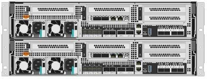
NetApp AFF A-Series controller lineup provides industry leading performance while continuing to provide a full suite of enterprise-grade data services for a shared environment across on-premises data centers and the cloud. Powered by NetApp ONTAP data management software, NetApp AFF A-Series systems deliver the industry’s highest performance, superior flexibility, and best-in-class data services and cloud integration to help you accelerate, manage, and protect business-critical data across your hybrid clouds. As the first enterprise-grade storage systems to support both FC-NVMe and NVMe-TCP, AFF A-Series systems boost performance with modern network connectivity. These systems deliver the industry’s lowest latency for an enterprise all-flash array, making them a superior choice for running the most demanding workloads and AI/DL applications. With a simple software upgrade to the modern FC-NVMe or NVMe-TCP SAN infrastructure, you can run more workloads with faster response times, without disruption or data migration.
NetApp offers a wide range of AFF-A series controllers to meet varying demands of the field. The high-end NetApp AFF A900 systems have a highly resilient design that enables non-disruptive in-chassis upgrades. It delivers latency as low as 100µs with FC-NVMe technology. The NetApp AFF A800 delivers high performance in a compact form factor and is especially suited for EDA and Media & Entertainment workloads. The midrange, most versatile NetApp AFF A400 system features hardware acceleration technology that significantly enhances performance and storage efficiency. The budget friendly, the NetApp AFF A150 is an excellent entry-level performance flash option for you.
For more information about the NetApp AFF A-series controllers, see the NetApp AFF product page: https://www.netapp.com/us/products/storage-systems/all-flash-array/aff-a-series.aspx
You can view or download more technical specifications of the NetApp AFF A-series controllers here: https://www.netapp.com/pdf.html?item=/media/7828-DS-3582-AFF-A-Series.pdf
Note: NetApp AFF A400 has been chosen for solution validation although any other AFF series could be used instead.
NetApp AFF A400
The NetApp AFF A400 offers full end-to-end NVMe support. The frontend FC-NVMe connectivity makes it possible to achieve optimal performance from an all-flash array for workloads that include artificial intelligence, machine learning, and real-time analytics as well as business-critical databases. The frontend NVMe-TCP connectivity enables you to take advantage of NVMe technology over existing ethernet infrastructure for faster host connectivity. On the back end, the NetApp AFF A400 supports both serial-attached SCSI (SAS) and NVMe-attached SSDs, offering the versatility for you to move up from your legacy A-Series systems and satisfying the increasing interest in NVMe-based storage.
The NetApp AFF A400 offers greater port availability, network connectivity, and expandability. The NetApp AFF A400 has 10 PCIe Gen3 slots per high availability pair. The NetApp AFF A400 offers 10GbE, 25GbE and 100GbE ports for IP based transport, and 16/32Gb ports for FC and FC-NVMe traffic. This model was created to keep up with changing business needs and performance and workload requirements by merging the latest technology for data acceleration and ultra-low latency in an end-to-end NVMe storage system.
Designed for enterprises that run all types of workloads in both SAN and NAS environments, the AFF A400 meets and exceeds all the demands, be it online transaction processing, virtualization, or file sharing. Running as fast as a high-end system that fits into a mid-range budget, it also stands out for its "NetApp signature" cloud integration, which enables easy cloud backup, tiering, caching and more, all built-in with the amazing ONTAP data management software.
For more information about the NetApp AFF A400 controllers, refer to the AFF A400 product page: https://www.netapp.com/data-storage/aff-a-series/aff-a400/
NetApp AFF C-Series Storage systems help move more data to flash with the latest high-density NVMe QLC capacity flash technology. These systems are suited for large-capacity deployment with a small footprint as an affordable way to modernize data center to all flash and also connect to the cloud. Powered by NetApp ONTAP data management software, NetApp AFF C-Series systems deliver industry-leading efficiency, superior flexibility, and best-in-class data services and cloud integration to help scale IT infrastructure, simplify data management, reduce storage cost, rack space usage, power consumption, and improve sustainability significantly.
NetApp offers several AFF C-series controllers to meet varying demands of the field. The high-end NetApp AFF C800 systems offer superior performance. The midrange NetApp AFF C400 delivers high performance and good expansion capability. The entry-level NetApp AFF C250 systems provide balanced performance, connectivity, and expansion options for a small footprint deployment.
For more information about the NetApp AFF C-series controllers, see the NetApp AFF C-Series product page: https://www.netapp.com/data-storage/aff-c-series/
You can view or download more technical specifications of the NetApp AFF C-Series controllers here: https://www.netapp.com/media/81583-da-4240-aff-c-series.pdf
You can look up the detailed NetApp storage product configurations and limits here: https://hwu.netapp.com/
Note: FlexPod CVDs provide reference configurations and there are many more supported IMT configurations that can be used for FlexPod deployments, including NetApp hybrid storage arrays.
NetApp ASA (All-flash SAN Array)
NetApp ASA, a family of modern all-flash block storage that’s designed for customers who need resilient, high-throughput, low-latency solutions for their mission-critical workloads. Many businesses see the benefit of SAN solutions. Especially when every minute of downtime can cost hundreds of thousands of dollars, or when poor performance prevents you from fulfilling your mission. Unified storage is often a convenient consolidated solution for file and block workloads, but customers might prefer a dedicated SAN system to isolate these workloads from others.
NetApp ASA is block optimized and supports NVMe/TCP and NVMe/FC as well as standard FC and iSCSI protocols. Building upon the foundation of well-architected SAN, ASA offers your organization the following benefits:
● Six nines (99.9999%) availability that’s backed by an industry-leading 6 Nines Data Availability Guarantee
● Massive scalability with the NetApp ONTAP cluster capability, which enables you to scale out ASA storage to more than 350PB of effective capacity
● Industry-leading storage efficiency that’s built-in and supported by a simple, straightforward Storage Efficiency Guarantee
● The most comprehensive cloud connectivity available
● Cost-effective integrated data protection
For more information about NetApp ASA, see the NetApp ASA product page: https://www.netapp.com/data-storage/all-flash-san-storage-array/
You can view or download more technical specifications of the NetApp ASA controllers here: https://www.netapp.com/media/87298-NA-1043-0523_ASA_AFF_Tech_Specs_HR.pdf
NetApp storage systems harness the power of ONTAP to simplify the data infrastructure from edge, core, and cloud with a common set of data services and 99.9999 percent availability. NetApp ONTAP 9 data management software from NetApp enables customers to modernize their infrastructure and transition to a cloud-ready data center. NetApp ONTAP 9 has a host of features to simplify deployment and data management, accelerate and protect critical data, and make infrastructure future-ready across hybrid-cloud architectures.
NetApp ONTAP 9.12.1 is the data management software that is used with the NetApp AFF A400 all-flash storage systems in this solution design. ONTAP software offers secure unified storage for applications that read and write data over block or file-access protocol storage configurations. These storage configurations range from high-speed flash to lower-priced spinning media or cloud-based object storage. ONTAP implementations can run on NetApp engineered AFF, FAS, or ASA series arrays and in private, public, or hybrid clouds (NetApp Private Storage and NetApp Cloud Volumes ONTAP). Specialized implementations offer best-in-class converged infrastructure, featured here as part of the FlexPod Datacenter solution or with access to third-party storage arrays (NetApp FlexArray virtualization). Together these implementations form the basic framework of the NetApp Data Fabric, with a common software-defined approach to data management, and fast efficient replication across systems. FlexPod and ONTAP architectures can serve as the foundation for both hybrid cloud and private cloud designs.
The NetApp AFF C-Series family of capacity flash storage system comes with NetApp ONTAP One, the all-in-one software license for on-premises operations. At any time, customers can start using and taking advantage of the rich ONTAP data management capabilities.
Read more about the capabilities of ONTAP data management software here: https://www.netapp.com/us/products/data-management-software/ontap.aspx.
For more information about the new features and functionality in the latest NetApp ONTAP software, refer to the NetApp ONTAP release notes: NetApp ONTAP 9 Release Notes (netapp.com)
Note: The support for the NetApp AFF A150 and the NetApp AFF C-Series platforms was introduced with ONTAP 9.12.1P1. The following sections provide an overview of how ONTAP 9.12.1 is an industry-leading data management software architected on the principles of software defined storage.
Heterogeneous Cluster
ONTAP 9.12.1 can run on multiple types of All flash, or FAS systems (with hybrid disks or spinning disks storage) and form a storage cluster. ONTAP 9.12.1 can also manage storage tier in cloud. Single storage ONTAP OS instance managing different storage tiers, makes efficient data tiering and workload optimization possible through single management realm.
NetApp Storage Virtual Machine
A NetApp ONTAP cluster serves data through at least one and possibly multiple storage virtual machines (SVMs; formerly called Vservers). An SVM is a logical abstraction that represents the set of physical resources of the cluster. Data volumes and network logical interfaces (LIFs) are created and assigned to an SVM and might reside on any node in the cluster to which the SVM has been given access. An SVM might own resources on multiple nodes concurrently, and those resources can be moved non-disruptively from one node in the storage cluster to another. For example, a NetApp FlexVol flexible volume can be non-disruptively moved to a new node and aggregate, or a data LIF can be transparently reassigned to a different physical network port. The SVM abstracts the cluster hardware, and thus it is not tied to any specific physical hardware.
An SVM can support multiple data protocols concurrently. Volumes within the SVM can be joined to form a single NAS namespace, which makes all SVM's data available through a single share or mount point to NFS and CIFS clients. SVMs also support block-based protocols, and LUNs can be created and exported by using iSCSI, FC, or FCoE. Any or all of these data protocols can be configured for use within a given SVM. Storage administrators and management roles can also be associated with SVM, which enables higher security and access control, particularly in environments with more than one SVM, when the storage is configured to provide services to different groups or set of workloads.
Storage Efficiencies
Storage efficiency has always been a primary architectural design point of ONTAP. A wide array of features allows businesses to store more data using less space. In addition to deduplication and compression, customers can store their data more efficiently by using features such as unified storage, multitenancy, thin provisioning, and NetApp Snapshot™ technology.
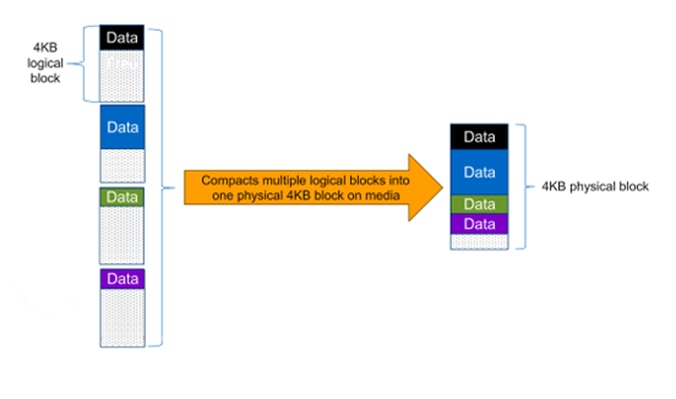
Starting with ONTAP 9, NetApp guarantees that the use of NetApp storage efficiency technologies on AFF systems reduces the total logical capacity used to store customer data by 75%, a data reduction ratio of 4:1. This space reduction is enabled by a combination of several different technologies, such as deduplication, compression, and compaction, which provide additional reduction to the basic features provided by ONTAP.
Compaction, which was introduced in ONTAP 9, is the patented storage efficiency technology released by NetApp. In the ONTAP WAFL file system, all I/O takes up 4KB of space, even if it does not actually require 4KB of data. Compaction combines multiple blocks that are not using their full 4KB of space together into one block. This one block can be more efficiently stored on the disk to save space. These storage efficiencies improve the ability of ONTAP to store more data in less space, reducing storage costs, and maximizing the effective capacity of your storage system.
Encryption
Data security continues to be an important consideration for customers purchasing storage systems. NetApp supported self-encrypting drives in storage clusters prior to ONTAP 9. However, in ONTAP 9, the encryption capabilities of ONTAP are extended by adding an Onboard Key Manager (OKM). The OKM generates and stores keys for each of the drives in ONTAP, allowing ONTAP to provide all functionality required for encryption out of the box. Through this functionality, known as NetApp Storage Encryption (NSE), sensitive data stored on disk is secure and can only be accessed by ONTAP.
Beginning with ONTAP 9.1, NetApp has extended the encryption capabilities further with NetApp Volume Encryption (NVE), a software-based mechanism for encrypting data. It allows a user to encrypt data at the volume level instead of requiring encryption of all data in the cluster, thereby providing more flexibility and granularity to ONTAP administrators. This encryption extends to Snapshot copies and NetApp FlexClone volumes that are created in the cluster. One benefit of NVE is that it runs after the implementation of the storage efficiency features, and, therefore, it does not interfere with the ability of ONTAP to create space savings. NVE unifies the data encryption capabilities available on-premises and extends them into the cloud. NVE is also FIPS 140-2 compliant. This compliance helps businesses adhere to federal regulatory guidelines for data at rest in the cloud.
ONTAP 9.7 introduced data-at-rest encryption as the default. Data-at-rest encryption is now enabled when an external or onboard key manager (OKM) is configured on the cluster or SVM. This means that all new aggregates created will have NetApp Aggregate Encryption (NAE) enabled and any volumes created in non-encrypted aggregates will have NetApp Volume Encryption (NVE) enabled by default. Aggregate level deduplication is not sacrificed, as keys are assigned to the containing aggregate during volume creation, thereby extending the native storage efficiency features of ONTAP without sacrificing security.
For more information about encryption in ONTAP, see the Encryption section in the NetApp ONTAP 9 Documentation Center.
FlexClone
NetApp FlexClone technology enables instantaneous point-in-time copies of a FlexVol volume without consuming any additional storage until the cloned data changes from the original. FlexClone volumes add extra agility and efficiency to storage operations. They take only a few seconds to create and do not interrupt access to the parent FlexVol volume. FlexClone volumes use space efficiently, applying the ONTAP architecture to store only data that changes between the parent and clone. FlexClone volumes are suitable for testing or development environments, or any environment where progress is made by locking-in incremental improvements. FlexClone volumes also benefit any business process where you must distribute data in a changeable form without endangering the integrity of the original.
SnapMirror (Data Replication)
NetApp SnapMirror is an asynchronous replication technology for data replication across different sites, or within the same data center, or on-premises datacenter to cloud, or cloud to on-premises datacenter. SnapMirror Synchronous (SM-S) offers volume granular, zero data loss protection. It extends traditional SnapMirror volume replication to synchronous mode meeting zero recovery point objective (RPO), disaster recovery, and compliance objectives. ONTAP extends support for SnapMirror Synchronous to application policy-based replication providing a simple and familiar configuration interface that is managed with the same tools as traditional SnapMirror. This includes ONTAP CLI, NetApp ONTAP System Manager, NetApp Active IQ Unified Manager, and NetApp Manageability SDK.
Quality of Service (QoS)
ONTAP allows you to set Minimum, Maximum, and Adaptive QoS for workloads. Here are the details:
● QoS Max (also known as Limits): Maximum performance level assigned to the storage object. This limits the amount of system resources that the workload can use. Often used to stop a workload from bullying/impacting other workloads. Max QoS can be set for SVM, Vol, LUN, File in ONTAP. It works by throttling throughput or IOPS at the network side.
● QoS Min (also known as Floors): Minimum "guaranteed" performance level assigned to the storage object. Min QoS can be set for Vol, or LUN in ONTAP.
● Adaptive QoS: A dynamic QoS policy that maintains IOPS/TB ratio as storage size (used or provisioned) changes. Adaptive QoS policy lets performance (IOPS) scale automatically with storage capacity (TB). Adaptive QoS can be set for volume.
● Service Level Management: Service level management is the management and monitoring of storage resources with respect to performance and capacity.
● Service Level Objective (SLO): The key tenets of service level management. SLOs are defined by a service level agreement in terms of performance and capacity.
NetApp Storage Sustainability
Data centers consume a significant amount of electricity and contribute to global greenhouse gas emissions. NetApp is providing lifetime carbon footprint estimates to help customers better understand the environmental impacts of NetApp storage systems.
NetApp uses Product Attribute to Impact Algorithm (PAIA) to calculate the carbon emissions associated with a product through its lifecycle, including acquisition of raw materials, manufacturing, distribution, product use, and final disposition. PAIA is a streamlined lifecycle assessment (LCA) methodology for assessing environmental impacts associated with the entire lifecycle of a product. The PAIA model was developed by the Materials Systems Laboratory at the Massachusetts Institute of Technology (MIT) and is a leading and globally accepted methodology for streamlining the product carbon footprint process.
Customers can use ONTAP REST API to access environment data from the ONTAP storage system for sustainability assessments. They can also utilize NetApp Harvest tool, which is an open-metrics endpoint for ONTAP and StorageGRID, to collect performance, capacity, hardware, and environmental metrics and display them in Grafana dashboards to gain sustainability insights.
Note: For more information on NetApp storage system environmental certifications and product carbon footprint report, ONTAP REST API, and NetApp Harvest, refer to the following references:
● https://www.netapp.com/company/environmental-certifications/
● https://docs.netapp.com/us-en/ontap-automation/reference/api_reference.html
● https://github.com/NetApp/harvest
NetApp Storage Security and Ransomware Protection
NetApp storage administrators use local or remote login accounts to authenticate themselves to the cluster and storage VM. Role-Based Access Control (RBAC) determines the commands to which an administrator has access. In addition to RBAC, NetApp ONTAP supports multi-factor authentication (MFA) and multi-admin verification (MAV) to enhance the security of the storage system.
With NetApp ONTAP, you can use the security login create command to enhance security by requiring that administrators log in to an admin or data SVM with both an SSH public key and a user password. Beginning with ONTAP 9.12.1, you can use Yubikey hardware authentication devices for SSH client MFA using the FIDO2 (Fast IDentity Online) or Personal Identity Verification (PIV) authentication standards.
With ONTAP 9.11.1, you can use multi-admin verification (MAV) to ensure that certain operations, such as deleting volumes or Snapshot copies, can be executed only after approvals from designated administrators. This prevents compromised, malicious, or inexperienced administrators from making undesirable changes or deleting data.
Also, with ONTAP 9.10.1, the Autonomous Ransomware Protection (ARP) feature uses workload analysis in NAS (NFS and SMB) environments to proactively detect and warn about abnormal activity that might indicate a ransomware attack. While NetApp ONTAP includes features like FPolicy, Snapshot copies, SnapLock, and Active IQ Digital Advisor to help protect from ransomware, ARP utilizes machine-learning and simplifies the detection of and the recovery from a ransomware attack. ARP can detect the spread of most ransomware attacks after only a small number of files are encrypted, take action automatically to protect data, and alert users that a suspected attack is happening. When an attack is suspected, the system takes a volume Snapshot copy at that point in time and locks that copy. If the attack is confirmed later, the volume can be restored to this proactively taken snapshot to minimize the data loss.
For more information on MFA, MAV, and ransomware protection features, refer to the following:
● https://docs.netapp.com/us-en/ontap/authentication/setup-ssh-multifactor-authentication-task.html
● https://www.netapp.com/pdf.html?item=/media/17055-tr4647pdf.pdf
● https://docs.netapp.com/us-en/ontap/multi-admin-verify/
● https://docs.netapp.com/us-en/ontap/anti-ransomware/
SnapCenter is a NetApp next-generation data protection software for tier 1 enterprise applications. SnapCenter, with its single-pane-of-glass management interface, automates and simplifies the manual, complex, and time-consuming processes associated with the backup, recovery, and cloning of multiple databases and other application workloads.
SnapCenter leverages technologies, including NetApp Snapshot copies, SnapMirror replication technology, SnapRestore data recovery software, and FlexClone thin cloning technology, which allows it to integrate seamlessly with technologies offered by Oracle, Microsoft, SAP, VMware, and MongoDB across FC, iSCSI, and NAS protocols. This integration allows IT organizations to scale their storage infrastructure, meet increasingly stringent SLA commitments, and improve the productivity of administrators across the enterprise.
Note: For more information on SnapCenter, refer to the SnapCenter software documentation: https://docs.netapp.com/us-en/snapcenter/index.html
SnapCenter is used in this solution for the following use cases:
● Backup and restore of VMware virtual machines.
● Backup, restore, protection and cloning of SQL Databases.
● Storage provisioning for SQL databases and logs.
SnapCenter Architecture
SnapCenter is a centrally managed web-based application that runs on a Windows platform and remotely manages multiple servers that must be protected.
Figure 13 illustrates the high-level architecture of the NetApp SnapCenter Server.
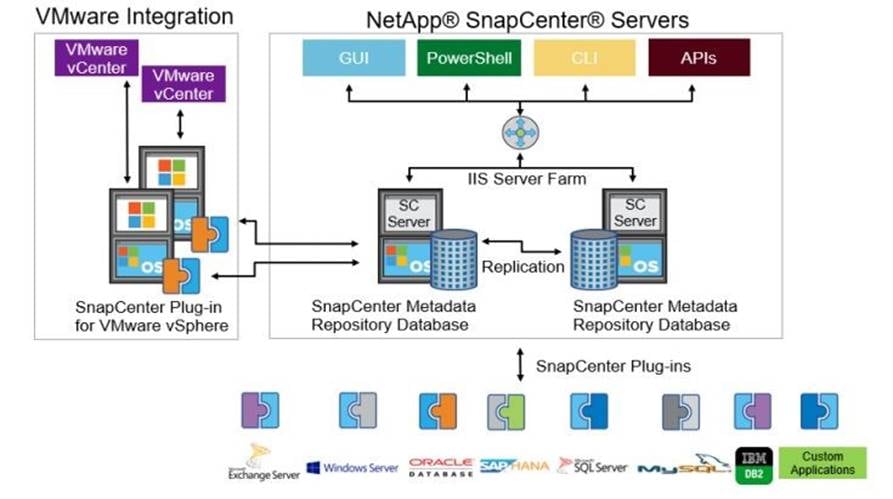
The SnapCenter Server has an HTML5-based GUI as well as PowerShell cmdlets and APIs. The SnapCenter Server is high-availability capable out of the box, meaning that if one SnapCenter host is ever unavailable for any reason, then the second SnapCenter Server can seamlessly take over and no operations are affected.
The SnapCenter Server can push out plug-ins to remote hosts. These plug-ins are used to interact with an application, a database, or a file system. In most cases, the plug-ins must be present on the remote host so that application- or database-level commands can be issued from the same host where the application or database is running.
To manage the plug-ins and the interaction between the SnapCenter Server and the plug-in host, SnapCenter uses SM Service, which is a NetApp SnapManager web service running on top of Windows Server Internet Information Services (IIS) on the SnapCenter Server. SM Service takes all client requests such as backup, restore, clone, and so on.
The SnapCenter Server communicates those requests to SMCore, which is a service that runs co-located within the SnapCenter Server and remote servers and plays a significant role in coordinating with the SnapCenter plugins package for Windows. The package includes the SnapCenter plug-in for Microsoft Windows Server and SnapCenter plug-in for Microsoft SQL Server to discover the host file system, gather database metadata, quiesce and thaw, and manage the SQL Server database during backup, restore, clone, and verification.
SnapCenter Plug-in for VMware vSphere (SCV) is another SnapCenter virtualization plug-in that manages virtual servers running on VMWare and that helps in discovering the host file system, databases on virtual machine disks (VMDK), and raw device mapping (RDM). SCV is a separate installation with an Open Virtual Appliance (OVA) based setup on the Linux-based Debian OS. The SCV details must be registered in SnapCenter Server to discover VMWare virtual resources.
SnapCenter Features
SnapCenter enables you to create application-consistent Snapshot copies and to complete data protection operations, including Snapshot copy-based backup, clone, restore, and backup verification operations. SnapCenter provides a centralized management environment, while using role-based access control (RBAC) to delegate data protection and management capabilities to individual application users across the SnapCenter Server and Windows hosts.
SnapCenter includes the following key features:
● A unified and scalable platform across applications and database environments and virtual and nonvirtual storage, powered by the SnapCenter Server.
● Consistency of features and procedures across plug-ins and environments, supported by the SnapCenter user interface.
● Role Based Access Control (RBAC) for security and centralized role delegation.
● Application-consistent Snapshot copy management, restore, clone, and backup verification support from both primary and secondary destinations (NetApp SnapMirror and SnapVault).
● Remote package installation from the SnapCenter GUI.
● Nondisruptive, remote upgrades.
● A dedicated SnapCenter repository for backup catalog and faster data retrieval.
● Load balancing implemented by using Microsoft Windows network load balancing (NLB) and application request routing (ARR), with support for horizontal scaling.
● Centralized scheduling and policy management to support backup and clone operations.
● Centralized reporting, monitoring, and dashboard views.
● Backup, restore, and data protection for VMware virtual machines, SQL Server Databases, Oracle Databases, MySQL, SAP HANA, MongoDB, and Microsoft Exchange.
● SnapCenter Plug-in for VMware in vCenter integration into the vSphere Web Client. All virtual machine backup and restore tasks are preformed through the web client GUI.
Using the SnapCenter Plug-in for SQL Server, you can do the following:
● Create policies, resource groups, and backup schedules for SQL Database.
● Backup SQL Databases and Logs.
● Restore SQL Databases (on Windows guest OS).
● Protect Database backup on secondary site for Disaster recovery.
● Protect Database backup on SnapVault for Archival.
● Create Database clone.
● Provision storage to Windows VMs for SQL Databases and Logs.
● Monitor backup and data protection operations.
● Generate reports of backup and data protection operations.
● Support RBAC security and centralized role delegation.
● Generate dashboard and reports that provide visibility into protected versus unprotected databases and status of backup, restore, and mount jobs.
Using the SnapCenter Plug-in for VMware in vCenter, you can do the following:
● Create policies, resource groups, and backup schedules for virtual machines.
● Backup virtual machines, VMDKs, and datastores.
● Restore virtual machines, VMDKs, and files and folders (on Windows guest OS).
● Attach and detach VMDK.
● Monitor and report data protection operations on virtual machines and datastores.
● Support RBAC security and centralized role delegation.
● Support guest file or folder (single or multiple) support for Windows guest OS.
● Restore an efficient storage base from primary and secondary Snapshot copies through Single File SnapRestore.
● Generate dashboard and reports that provide visibility into protected versus unprotected virtual machines and status of backup, restore, and mount jobs.
● Attach or detach virtual disks from secondary Snapshot copies.
● Attach virtual disks to an alternate virtual machine.
Microsoft SQL Server Database Storage Layout with SnapCenter
SnapCenter best practice considerations for Microsoft SQL Server database layout are aligned with the suggested Microsoft SQL Server deployment. SnapCenter supports backup only of user databases that reside on a NetApp storage system. Along with the performance benefit of segregating user database layout into different volumes, SnapCenter also has a large influence on the time required to back up and restore. Separate volumes for data and log files significantly improve the restore time as compared to a single volume hosting multiple user data files. Similarly, user databases with I/O-intensive applications might experience increased backup time.
Consider the following storage layout data points for backing up databases with SnapCenter:
● Databases with I/O intensive queries throughout the day should be isolated in different volumes and eventually have separate jobs to back them up.
● Large databases and databases that have minimal RTO should be placed in separate volumes for faster recovery.
● Small to medium-size databases that are less critical or that have fewer I/O requirements should be consolidated into a single volume. Backing up many databases residing in the same volume results in fewer Snapshot copies to be maintained. NetApp also recommends consolidating Microsoft SQL Server instances to use the same volumes to control the number of backup Snapshot copies taken.
● Create separate LUNs to store full text-related files and file-streaming-related files.
● Assign a separate LUN for each instance to store Microsoft SQL server log backups. The LUNs can be part of the same volume.
● System databases store database server metadata, configurations, and job details; they are not updated frequently. System databases and tempdb should be placed in separate drives or LUNs. Do not place system databases in same volume as user databases. User databases have different backup policies, and the frequency of user database backups is not same as for system databases.
● With Microsoft SQL Server availability group setup, the data and log files for replicas should be placed in an identical folder structure on all nodes.
Best Practices
The following are the NetApp recommendations on volume design for optimal performance:
● Allocate at least 10 percent of available free space in an aggregate.
● Use flexible volumes to store Microsoft SQL Server database files and do not share volumes between hosts.
● Use NTFS mount points instead of drive letters to avoid the 26-drive letter limitation in Microsoft Windows Server.
Note: When using volume mount points, NetApp recommends giving the volume label the same name as the mount point.
● Configure a volume auto size policy, when appropriate, to help prevent out-of-space conditions.
● When the SQL Server database I/O profile consists mostly of large sequential reads, such as with decision support system workloads, enable read reallocation on the volume. Read reallocation optimizes the blocks for better performance.
● Set the Snapshot copy reserve value in the volume to zero for ease of monitoring from an operational perspective.
● Disable storage Snapshot copy schedules and retention policies. Instead, use the SnapCenter for SQL Server plug-in to coordinate Snapshot copies of the Microsoft SQL Server data volumes.
● Microsoft SQL Server uses the system database tempdb as a temporary workspace, especially for I/O intensive database consistency checker (DBCC) CHECKDB operations. Therefore, place this database on a dedicated volume with a separate set of spindles. In large environments where volume count is a challenge, you can consolidate tempdb into fewer volumes and store it in the same volume as other system databases. This procedure requires careful planning. Data protection for tempdb is not a high priority because this database is re-created every time the SQL Server is restarted.
● Place user data files (.mdf) on separate volumes because they are random read/write workloads. It is common to create transaction log backups more frequently than database backups. For this reason, place transaction log files (.ldf) on a separate volume or VMDK from the data files so that independent backup schedules can be created for each. This separation also isolates the sequential write I/O of the log files from the random read/write I/O of data files and significantly improves Microsoft SQL Server performance.
NetApp ONTAP Tools for VMware vSphere
The NetApp ONTAP tools for VMware vSphere provides end-to-end life cycle management for virtual machines in VMware environments that use NetApp storage systems. It simplifies storage and data management for the VMware environment by enabling administrators to directly manage storage within the vCenter Server.
Note: Each component in NetApp ONTAP tools provides capabilities to help manage your storage more efficiently.
Virtual Storage Console (VSC)
VSC enables you to perform the following tasks:
● Add storage controllers, assign credentials, and set up permissions for storage controllers of VSC, that both SRA and VASA Provider can leverage
● Provision datastores
● Manage access to the vCenter Server objects and NetApp ONTAP objects by using the vCenter Server role-based access control (RBAC) and NetApp ONTAP RBAC
VASA Provider
VASA Provider for NetApp ONTAP uses VMware vSphere APIs for Storage Awareness (VASA) to send information about storage used by VMware vSphere to the vCenter Server. NetApp ONTAP tools has VASA Provider integrated with VSC. VASA Provider enables you to perform the following tasks:
● Provision VMware Virtual Volumes (vVols) datastores
● Create and use storage capability profiles that define different storage service level objectives (SLOs) for your environment.
● Monitor the performance of virtual machine disks (VMDKs) and the virtual machines that are created on vVols datastores.
Storage Replication Adapter (SRA)
SRA enables you to use array-based replication (ABR) for protected sites and recovery sites for disaster recovery in the event of a failure. When SRA is enabled and used in conjunction with VMware Site Recovery Manager (SRM), you can recover the vCenter Server datastores and virtual machines in the event of a failure.
Note: NetApp ONTAP tools for VMware vSphere 9.12 release supports and interoperates with VMware vSphere 8.0. For more information on NetApp ONTAP tools for VMware vSphere, go to: https://docs.netapp.com/us-en/ontap-tools-vmware-vsphere/index.html
NetApp Active IQ Unified Manager
NetApp Active IQ Unified Manager is a comprehensive monitoring and proactive management tool for NetApp ONTAP systems to help manage the availability, capacity, protection, and performance risks of your storage systems and virtual infrastructure. The Unified Manager can be deployed on a Linux server, on a Windows server, or as a virtual appliance on a VMware host.
Active IQ Unified Manager enables monitoring your ONTAP storage clusters from a single redesigned, intuitive interface that delivers intelligence from community wisdom and AI analytics. It provides comprehensive operational, performance, and proactive insights into the storage environment and the virtual machines running on it. When an issue occurs with the storage infrastructure, Unified Manager can notify you about the details of the issue to help with identifying the root cause. The virtual machine dashboard gives you a view into the performance statistics for the VM so that you can investigate the entire I/O path from the vSphere host down through the network and finally to the storage. Some events also provide remedial actions that can be taken to rectify the issue.
You can configure custom alerts for events so that when issues occur, you are notified through email and SNMP Traps. Active IQ Unified Manager enables planning for the storage requirements of your users by forecasting capacity and usage trends to proactively act before issues arise, preventing reactive short-term decisions that can lead to additional problems in the long term.
For more information on NetApp Active IQ Unified Manager, go to: https://docs.netapp.com/us-en/active-iq-unified-manager/
NetApp BlueXP is a unified control plane that provides a hybrid multicloud experience for storage and data services across on-premises and cloud environments. NetApp BlueXP is an evolution of NetApp Cloud Manager and enables the management of your NetApp storage and data assets from a single interface.
You can use BlueXP to move, protect, and analyze data, and to control on-prem storage devices like ONTAP, E-Series, and StorgeGRID, and to create and administer cloud storage (for example, Cloud Volumes ONTAP and Azure NetApp Files).
The BlueXP backup and recovery service provides efficient, secure, and cost-effective data protection for NetApp ONTAP data, Kubernetes persistent volumes, databases, and virtual machines, both on-premises and in the cloud. Backups are automatically generated and stored in an object store in your public or private cloud account.
BlueXP ransomware protection provides a single point of visibility and control to manage and to refine data security across various working environments and infrastructure layers to better respond to threats as they occur.
Note: For more information on BlueXP, refer to the BlueXP documentation: https://docs.netapp.com/us-en/bluexp-family/
NetApp Cloud Volumes ONTAP (CVO)
NetApp Cloud Volumes ONTAP is a software-defined storage offering that delivers advanced data management for file and block workloads. With Cloud Volumes ONTAP, you can optimize your cloud storage costs and increase application performance while enhancing data protection, security, and compliance.
Key features include:
● Storage efficiencies
Leverage built-in data deduplication, data compression, thin provisioning, and cloning to minimize storage costs.
● High availability
Ensure enterprise reliability and continuous operations in case of failures in your cloud environment.
● Data protection
Cloud Volumes ONTAP leverages SnapMirror, NetApp’s industry-leading replication technology, to replicate on-premises data to the cloud so it’s easy to have secondary copies available for multiple use cases.
Cloud Volumes ONTAP also integrates with BlueXP backup and recovery to deliver backup and restore capabilities for protection, and long-term archive of your cloud data.
● Data tiering
Switch between high and low-performance storage pools on-demand without taking applications offline.
● Application consistency
Ensure consistency of NetApp Snapshot copies using NetApp SnapCenter.
● Data security
Cloud Volumes ONTAP supports data encryption and provides protection against viruses and ransomware.
● Privacy compliance controls
Integration with BlueXP classification helps you understand data context and identify sensitive data.
Note: For more information on Cloud Volumes ONTAP, go to: https://docs.netapp.com/us-en/bluexp-cloud-volumes-ontap/
Connector is an instance which enables NetApp BlueXP to manage resources and process within public cloud environment. A Connector is required to use many features which BlueXP provides. A Connector can be deployed in the cloud or on-premises network.
Connector is supported in the following locations:
● Amazon Web Services
● Microsoft Azure
● Google Cloud
● On premises
When you create your first Cloud Volumes ONTAP working environment, BlueXP will prompt you to create a Connector if you don’t have one yet. The user who creates a Connector from BlueXP needs specific permissions to deploy the instance in cloud provider of choice. BlueXP will remind you of the permissions requirements when you create a Connector.
The Connector needs specific cloud provider permissions to perform operations on your behalf. For example, to deploy and manage Cloud Volumes ONTAP. When you create a Connector directly from BlueXP, BlueXP creates the Connector with the permissions that it needs. To learn more about Connectors, refer to Connectors.
VMware vSphere is a virtualization platform for holistically managing large collections of infrastructures (resources including CPUs, storage, and networking) as a seamless, versatile, and dynamic operating environment. Unlike traditional operating systems that manage an individual machine, VMware vSphere aggregates the infrastructure of an entire data center to create a single powerhouse with resources that can be allocated quickly and dynamically to any application in need.
VMware vSphere 8.0 has several improvements and simplifications including, but not limited to:
● Limits with VMware vSphere 8.0 have been increased including the number of GPU devices increased to 8, the number of ESXi hosts that can be managed by Lifecycle Manager is increased from 400 to 1000, the maximum number of VMs per cluster is increased from 8,000 to 10,000, and the number of VM DirectPath I/O devices per host is increased from 8 to 32.
● Security improvements including adding an SSH timeout on ESXi hosts, a TPM Provisioning policy allowing a vTPM to be replaced when cloning VMs, and TLS 1.2 as the minimum supported TLS version.
● Implementation of VMware vMotion Unified Data Transport (UDT) to significantly reduce the time to storage migrate powered off virtual machines.
● Lifecycle Management improvements including VMware vSphere Configuration Profiles as a new alternative to VMware Host Profiles, staging cluster images and remediating up to 10 ESXi hosts in parallel instead of one at a time.
● New Virtual Hardware in VM hardware version 20 supporting the latest guest operating systems, including Windows 11.
● Distributed Resource Scheduler and vMotion improvements.
● Implementation of the VMware Balanced Power Management Policy on each server, which reduces energy consumption with minimal performance compromise.
● Implementation of VMware Distributed Power Management, which along with configuration of the Intelligent Platform Management Interface (IPMI) on each Cisco UCS server allows a VMware host cluster to reduce its power consumption by powering hosts on and off based on cluster resource utilization.
For more information about VMware vSphere and its components, go to: https://www.vmware.com/products/vsphere.html
Windows Server 2022 is the latest OS platform release from Microsoft. Windows Server 2022 is an excellent platform for running Microsoft SQL Server 2022 databases. It offers new features and enhancements related to security, patching, domains, clusters, storage, and support for various new hardware features, and so on. It enables Windows Server to provide best-in-class performance and a highly scalable platform for deploying SQL Server databases.
SQL Server 2022 (16.x) is the latest relational database from Microsoft and builds on previous releases to grow SQL Server as a platform that gives you choices of development languages, data types, on-premises or cloud environments, and operating systems. It offers various enhancements and new features that enables SQL Server deployments more reliable, highly available, performant, and secured than ever. SQL Server 2022 can leverage new hardware capabilities from partners like Intel like to provide extended capabilities. It can leverage Intel Quick Assist Technology (QAT) for offloading backup compression thereby improving backups and restores performance; Intel Advanced Vector Extension-512 can be leveraged by SQL Server 2022 engine to improve batch mode operations.
For more details about the new capabilities of SQL Server 2022, go to: https://learn.microsoft.com/en-us/sql/sql-server/what-s-new-in-sql-server-2022?view=sql-server-ver16
This chapter contains the following:
● NetApp AFF A400 – Storage Virtual Machine (SVM) Design
● VMware vSphere – ESXi Design
The FlexPod Datacenter with Cisco UCS M7 solution delivers a cloud-managed infrastructure solution on the latest Cisco UCS hardware. The VMware vSphere 8.0 hypervisor is installed on the Cisco UCS X210c M7 Compute Nodes and these servers are configured for stateless compute design using boot from SAN. The NetApp AFF A400 provides the storage infrastructure required for setting up the VMware environment. The Cisco Intersight cloud-management platform is utilized to configure and manage the infrastructure.
The FlexPod Datacenter with Cisco UCS M7 design meets the following general requirements:
● Resilient design across all layers of the infrastructure with no single point of failure
● Scalable design with the flexibility to add compute capacity, storage, or network bandwidth as needed
● Modular design that can be replicated to expand and grow as the needs of the business grow
● Flexible design that can support different models of various components with ease
● Simplified design with ability to integrate and automate with external automation tools
● Cloud-enabled design which can be configured, managed, and orchestrated from the cloud using GUI or APIs
FlexPod is a defined set of hardware and software that serves as an integrated foundation for both virtualized and non-virtualized solutions. VMware vSphere built on FlexPod includes NetApp All Flash FAS storage, Cisco Nexus networking, Cisco Unified Computing System, and VMware vSphere software in a single package. The design is flexible enough that the networking, computing, and storage resources can fit in one datacenter rack or be deployed according to a customer's datacenter design. Port density enables the networking components to accommodate multiple configurations of this kind.
FlexPod Datacenter with Cisco UCS M7 supports both IP and Fibre Channel (FC)—based storage access design. This CVD covers the IP-based solution. For this solution, iSCSI configuration on Cisco UCS and NetApp AFF A400 is utilized to set up boot from SAN for the Compute Node. VMware ESXi hosts access the VM datastore volumes on NetApp using NFS. The physical connectivity details for IP-based design are explained below.
Figure 14 shows the FlexPod components and the network connections for a configuration with Cisco UCS 6536 Fabric Interconnects. This design can support end to end 100-Gbps Ethernet connections between the NetApp AFF A400 storage array and Cisco UCS X210c M7 compute nodes.
The physical topology for the IP-based FlexPod Datacenter is shown below.
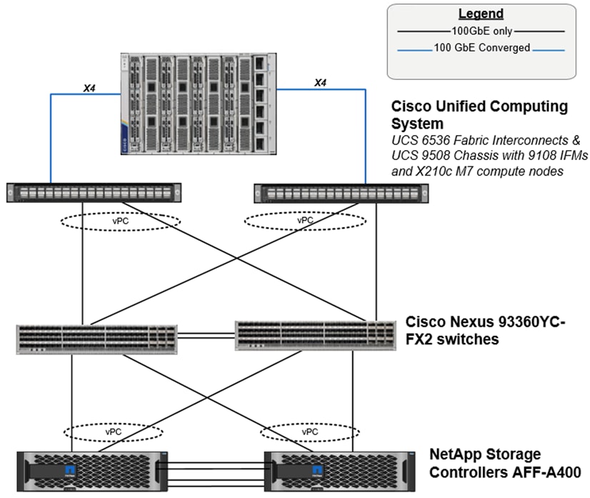
Figure 14 shows a base design. Each of the components can be scaled easily to support specific business requirements. For example, more (or different) servers or blade chassis can be deployed to increase computing capacity, additional storage controllers or disk shelves can be deployed to improve I/O capability and throughput, and special hardware or software features can be added to introduce new features.
The following components were used to validate and test the solution:
● One Cisco UCSX-9508 blade chassis with Cisco UCS 9108 IFM modules
● Four Cisco UCS X210c M7 compute nodes with the Cisco UCS VIC 15231
● Two Cisco Nexus 93360YC-FX2 Switches
● Two Cisco UCS 6536 Fabric Interconnects
● One NetApp AFF A400 (high-availability pair) running clustered NetApp ONTAP with NVMe disk shelves
To validate the IP-based storage access in this FlexPod configuration, the components are set up as follows:
● Cisco UCS 6536 Fabric Interconnects provide the chassis and network connectivity.
● The Cisco UCS X9508 Chassis connects to fabric interconnects using Cisco UCSX-I-9108-100G intelligent fabric modules (IFMs), where four 100 Gigabit Ethernet ports are used on each IFM to connect to the appropriate FI. If additional bandwidth is required, all eight 100G ports can be utilized. The Cisco UCSX-I-9108-25G IFMs can also be used with 4x25G breakout cables used to connect the chassis to the fabric interconnects.
● Cisco UCSX-210c M7 Compute Nodes contain fifth-generation Cisco 15231 virtual interface cards (VICs) which are used for 100Gbps connectivity on each side of fabric interconnect.
● Cisco Nexus 93360YC-FX2 Switches in Cisco NX-OS mode provide the switching fabric.
● Cisco UCS 6536 Fabric Interconnect 100-Gigabit Ethernet uplink ports connect to Cisco Nexus 93360YC-FX2 Switches in a Virtual Port Channel (vPC) configuration.
● The NetApp AFF A400 controllers connect to the Cisco Nexus 93360YC-FX2 Switches using two 100 GE ports from each controller configured as a vPC.
● VMware 8.0 ESXi software is installed on Cisco UCS X210c M7 Compute Nodes and servers to validate the infrastructure.
In this solution, VMware ESXi 8.0 virtual environment was tested and validated for deployment of Microsoft SQL Server 2022 databases on virtual machines running Microsoft Windows Server 2022 guest operating system. SQL Server virtual machines are configured to connect the NetApp AFF A400 storage LUNs directly using the in-guest Microsoft software iSCSI initiator. This approach bypasses the ESXI hypervisor VMFS storage layer for the LUNs that are used for storing SQL Server database files. This design approach provides better performance, simplifies management, enables efficient backup of data, and allows the association of storage QoS directly to objects hosting SQL Server data.
The following tables lists the hardware and software components and the image versions used in the solution.
Table 1. Hardware and Software components used in the solution
| Component Name |
Details |
Image version |
Quantity |
| Computing |
UCS X-Series blade chassis can host combination of X210c M7 compute nodes and a pool of IO resources that include GPU accelerators, disk storage and non-volatile memory. The Chassis has UCS 9108 100G IFM proving 100G connectivity to the compute nodes on each side of the Fabric. |
|
1 |
| UCS X210c M7 compute node |
Each node is equipped with 2x Intel 4th generation Xeon Scalable 6448H processors each with 32 cores running at 2.4GHz base frequency. Each node has 16x 32G memory (total of 512GB) running at 4800 MTs. Each compute node has one UCS VIC 15231 providing 100Gbps connectivity on each side of the Fabric. |
5.1(1.230052) |
4 |
| Cisco UCS 6536 Fabric Interconnect |
Cisco UCS 6536 Fabric Interconnect providing both network connectivity and management capabilities for the system. |
4.2(3d) |
2 |
| Cisco Nexus Switches |
Cisco Nexus 93360YC-FX2 providing management and storage traffic |
NXOS: version 10.2(5) |
2 |
| NetApp AFF A400 storage |
NetApp AFF A-Series All Flash Array providing storage for the entire FlexPod system |
ONTAP 9.12.1P4 |
1 HA pair |
| Component Name |
Details |
Version |
| VMware vSphere 8.0 |
VMware vSphere ESXi 8.0 Hypervisor |
8.0 |
| VMware vCenter Appliance |
VMware vCenter for managing vSphere environment |
8.0 |
| Microsoft Windows Server |
Windows Server Guest Operating System |
2022 |
| Microsoft SQL Server |
Relation database from Microsoft |
2022 (16.0.1000.6) |
| HammerDB |
Testing tool used for generating OLTP workload on SQL Server databases |
4.8 |
| NetApp SnapCenter |
For Virtual machine file system level as well as SQL Server database level backups and restore |
4.8 |
| NetApp Active IQ Unified Manager |
NetApp Storage monitoring |
9.12 |
| NetApp ONTAP tools for VMware vSphere |
For datastore storage provisioning to ESXi hosts |
9.12 |
| NetApp Cloud Volumes ONTAP |
Deployed for testing Disaster Recovery of SQL Server databases |
9.13.1 |
| NetApp BlueXP |
For managing on-prem ONTAP and CVO storage |
3.9.32 |
VLAN Configuration
Table 3 lists the VLANs configured for setting up the IP-based FlexPod environment along with their usage.
| VLAN ID |
Name |
Usage |
| 2 |
Native-VLAN |
Use VLAN 2 as native VLAN instead of default VLAN (1) |
| 1020 |
OOB-MGMT-VLAN |
Out-of-band management VLAN to connect management ports for various devices |
| 1023 |
SQL-MGMT-VLAN |
In-band management VLAN utilized for all in-band management connectivity - for example, ESXi hosts, VM management, and so on |
| 3053 |
SQL-NFS-VLAN |
NFS VLAN for mounting datastores in ESXi servers for VMs |
| 3013 |
SQL-iSCSI-A |
iSCSI-A path for boot-from-san traffic as well as SQL VM storage traffic |
| 3023 |
SQL-iSCSI-B |
iSCSI-B path for boot-from-san traffic as well as SQL VM storage traffic |
| 3000 |
vMotion |
VMware vMotion traffic |
Some of the key highlights of VLAN usage are as follows:
● VLAN 1020 allows you to manage and access out-of-band management interfaces of various devices and is brought into the infrastructure to allow CIMC access to the Cisco UCS servers and is also available to infrastructure virtual machines (VMs). Interfaces in this VLAN are configured with MTU 1500.
● VLAN 1023 is used for in-band management of SQL VMs, ESXi hosts, and other infrastructure services. Interfaces in this VLAN are configured with MTU 1500. Optionally, a different VLAN can be used for separating SQL VM management traffic from in-band management traffic.
● VLAN 3053 provides ESXi hosts access to the NFS datastores hosted on the NetApp Controllers for deploying VMs. Interfaces in this VLAN are configured with MTU 9000.
● A pair of iSCSI VLANs (3013 and 3023) is configured to provide access to boot LUNs for ESXi hosts and iSCSI datastores. These VLANs are not needed when configuring Fibre Channel connectivity. Interfaces in these VLANs are configured with MTU 9000.
● VLAN 3000 is used for vMotion of VMs from one ESXi host to another and the interfaces in this VLAN are configured with MTU 9000.
In FlexPod Datacenter deployments, each Cisco UCS server equipped with a Cisco Virtual Interface Card (VIC) is configured for multiple virtual Network Interfaces (vNICs), which appear as standards-compliant PCIe endpoints to the OS. The end-to-end logical connectivity including VLAN/VSAN usage between the server profile for an ESXi host and the storage configuration on NetApp AFF A400 controllers is described below.
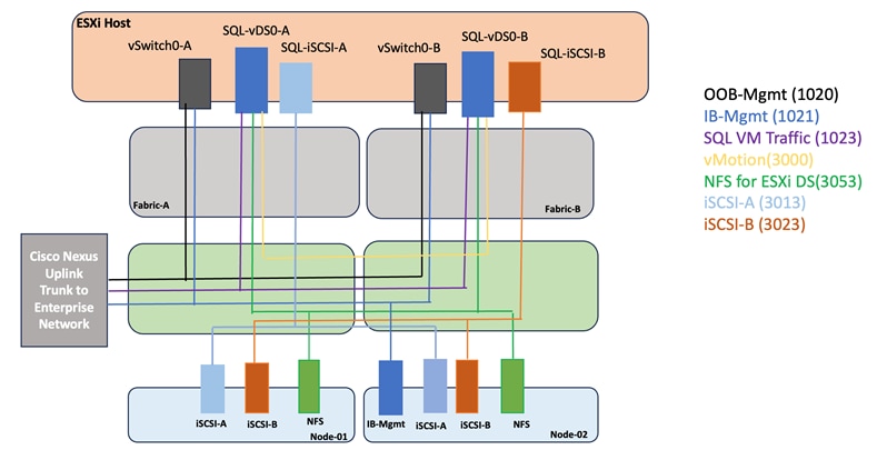
Optionally, IB-Mgmt and SQL-Mgmt traffics can be combined and single VLAN (for instance VLAN 1023) can be used for both the traffics.
Each ESXi server profile supports:
● Managing the ESXi hosts using a common management segment.
● Diskless SAN boot using iSCSI with persistent operating system installation for true stateless computing.
● Six vNICs where:
◦ Two redundant vNICs (vSwitch0-A and vSwitch0-B) carry management. The MTU value for these vNICs is set as a 1500 can be placed on these vNICs.
◦ Two redundant vNICs (SQL-vDS0-A and SQL-vDS0-B) are used by the first vSphere Distributed switch (vDS) and carry NFS data traffic, VMware vMotion traffic and your application data traffic. The MTU for the vNICs is set to Jumbo MTU (9000), but interfaces that require MTU 1500 can be placed on these vNICs.
◦ Two vNICs (SQL-iSCSi-A and SQL-iSCSi-B) are used by the SQL-iSCSI-vDS vDS. The iSCSI VLANs are set as native on the corresponding vNICs. The MTU value for the vNICs and all interfaces on the vDS is set to Jumbo MTU (9000). The initial VMware ESXi setup utilizes two vSwitches, but the vNICs and VMkernel ports are migrated to the second vDS.
● Each ESXi host (compute node) mounts VM datastores from NetApp AFF A400 controllers using NFS for deploying virtual machines.
NetApp AFF A400 – Storage Virtual Machine (SVM) Design
To provide the necessary data segregation and management, a dedicated SVM (SQL-SVM) is created for hosting the VMware environment. The SVM contains the following volumes and logical interfaces (LIFs):
● Volumes
◦ ESXi boot volume (esxi_boot) that consists of ESXi boot LUNs, used to enable ESXi host boot using iSCSI boot from SAN. The boot LUNs are 128GB in size and thin provisioned as per VMware recommendation.
◦ Infrastructure datastores used by the vSphere environment to store the VMs and swap files. Separate datastores to be configured for NFS volumes and iSCSI data and log LUNs.
◦ Datastore used by the vSphere environment to host vSphere Cluster Services (vCLS) VMs. By default, the datastore placement logic chooses an available datastore hence it is recommended to create a dedicated datastore for vCLS VMs.
Note: It is a NetApp best practice to create Load sharing mirror for each SVM root volume that serves NAS data in the cluster. For more information on LSM, go to: https://docs.netapp.com/us-en/ontap/data-protection/manage-snapmirror-root-volume-replication-concept.html
● Logical Interfaces (LIFs)
◦ NFS LIFs to mount NFS datastores in the VMware vSphere environment.
◦ iSCSI A/B LIFs to connect to ESXi boot LUNs or application data using iSCSI protocol
Each LIF belongs to specific VLANs assigned for that traffic. For IP based LIFs, IP addresses are assigned from subnets assigned to the respective VLAN. The IP based LIFs configured for IP SAN storage (iSCSI here) require 2 IP addresses per controller to allow all 4 paths between the end host and storage. LIFs configured for NFS require one IP address per controller.
A visual representation of volumes and logical interfaces (LIFs) is shown in Figure 16 for iSCSI boot.
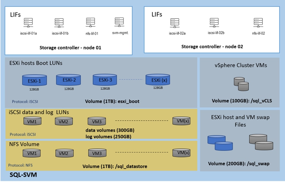
Multiple vNICs are created for the ESXi hosts using the Cisco Intersight server profile and are then assigned to specific virtual and distributed switches. The vNIC distribution for the ESXi hosts is as follows:
● Two vNICs (one on each fabric) for vSwitch0 to support core services such as in band management of ESXi hosts . The standard VMware-Default Cisco UCS Ethernet adapter policy is assigned to these vNICs.
● Two vNICs (one on each fabric) for a vSphere Virtual Distributed Switch (SQL-vDS0) to support SQL management traffic, infrastructure NFS data traffic, and vMotion traffic. In this vDS, vMotion is pinned to Cisco UCS Fabric B so that vMotion is switched in the B-side fabric interconnect. A maximum performance VMware-5G-16RXQs Cisco UCS Ethernet adapter policy utilizing receive side scaling (RSS) is assigned to these vNICs.
● Two vNICs (one on each fabric) for the vSphere Virtual Distributed Switch (SQL-iSCSI-vDS) to support iSCSI (including boot) and direct storage access to the SQL virtual machines using in-guest iSCSI initiator. In this vDS, iSCSI VMkernel ports are pinned to the appropriate fabric. A maximum performance VMware-5G-16RXQs Cisco UCS Ethernet adapter policy, utilizing receive side scaling (RSS) and maximum buffer size is assigned to these vNICs.
This chapter contains the following:
● Cisco UCS Configuration using Cisco Intersight
● NetApp ONTAP Storage Configuration
● NetApp ONTAP Boot Storage Setup
● Finalize the NetApp ONTAP Storage Configuration
● FlexPod Management Tools Setup
● VMware vSphere ESXi Configuration
● Provision VMware ESXi Datastores for Windows Virtual Machines using NetApp ONTAP tools
● Virtual Machine Configuration for Hosting SQL Server Database
● Guest Operating System Installation and Configuration for NetApp Storage access over iSCSI
● Microsoft SQL Server Installation and Configuration
● SnapCenter Configuration for SQL Database Backup, Restore, Cloning, and Protection
Note: This documentation does not list all the steps for deploying FlexPod Datacenter. Refer to the base infrastructure Cisco Validated Design documentation for more details on the solution design and deployment steps here:
● FlexPod Datacenter with Cisco UCS M7 and vSphere 8.0 – Design Guide
● FlexPod Datacenter with End-to-End 100G, Cisco UCS X-Series, IMM mode – Deployment Guide
This section discusses only the specific Cisco UCS policies used in this FlexPod Datacenter solution and which are different from the base FlexPod infrastructure configuration. These policies are important for obtaining optimal performance for SQL Server workloads.
On each Cisco Nexus Switch, required VLANs, Port Channels, vPC Domain and vPC-Peer links configuration need to be done. For the IP-based deployment using iSCSI protocol, these configurations, except the ethernet interface port numbers and VLAN numbers, are standard and no different than what is explained in the base infrastructure CVD. Please refer to the Cisco Nexus switch configuration in the base infrastructure CVD here:
Cisco UCS Configuration using Cisco Intersight
This section provides more details on the specific Cisco UCS polices and settings used for configuring Cisco UCS X210c M7 compute node for hosting critical Microsoft SQL Server database virtual machines on vSphere ESXi environment. The Cisco UCS X210c M7 blades are installed in the Cisco UCS X9508 chassis and are connected to a pair of Cisco UCS 6536 Fabric Interconnects. The Cisco UCS fabric interconnects are managed by Intersight.
Note: It is important to use the correct network and storage adapter policies for low latency and better storage bandwidth, since the underlying Cisco VIC resources are shared between various types of traffic such as virtual machine management traffic, storage access, ESXi host management, vMotion, and so on.
LAN Connectivity Policies
The following vNICs are defined in a LAN connectivity policy to derive the vNICs for the ESXi host networking. The LAN connectivity policy is then used in Server profiles template to derive the Server profile.
● 00-vSwitch0-A: Used for ESXi host management traffic over Fabric A.
● 01-vSwitch0-B: Used for ESXi host management traffic over Fabric B.
● 02-vDS0-A: Used for infrastructure management traffic such as vMotion, NFS storage access, and SQL Server virtual machine management traffic over Fabric A.
● 03-vDS0-B: Used for infrastructure management traffic such as vMotion, NFS storage access, and SQL Server virtual machine management traffic over Fabric B
● 04-iSCSI-A: Used for booting the ESXi host from the NetApp storage array boot LUNs and direct NetApp storage access by SQL Server Guest Windows VMs using in-guest iSCSI protocol over Fabric A.
● 05-iSCSI-B: Used for booting the ESXi host from the NetApp storage array boot LUNs and direct NetApp storage access by SQL Server Guest Windows VMs using in-guest iSCSI protocol over Fabric B.
Table 4 list the additional configuration details of the above vNICs used in this reference architecture.
| vNICs |
00-vSwitch-A |
01-vSwitch-B |
02-vDS0-A |
03-vDS0-B |
04-iSCSI-A |
05-iSCSI-B |
| Slot ID and PCI Link |
Auto for Slot and PCI Link |
Auto for Slot and PCI Link |
Auto for Slot and PCI Link |
Auto for Slot and PCI Link |
Auto for Slot and PCI Link |
Auto for Slot and PCI Link |
| PCI Order |
0 |
1 |
2 |
3 |
4 |
5 |
| Switch ID |
A |
B |
A |
B |
A |
B |
| Fabric Failover |
Disabled |
Disabled |
Disabled |
Disabled |
Disabled |
Disabled |
| Network Group Policy for list of Allowed VLANs and Native VLAN |
1020,1023 and 1023 |
1020,1023 and 1023 |
1023,3000,3053 and 2 |
1023,3000,3053 and 2 |
3013 and 3013 |
3023 and 3023 |
| Network Control Policy for CDP and LLDP |
CDP and LLDP Enabled |
CDP and LLDP Enabled |
CDP and LLDP Enabled |
CDP and LLDP Enabled |
CDP and LLDP Enabled |
CDP and LLDP Enabled |
| QoS & MTU |
Best Effort and 9000 |
Best Effort and 9000 |
Best Effort and 9000 |
Best Effort and 9000 |
Best Effort and 9000 |
Best Effort and 9000 |
| Ethernet Adapter Policy |
EthAdapter-VMware-Policy |
EthAdapter-VMware-Policy |
EthAdapter-16RXQs |
EthAdapter-16RXQs |
EthAdapter-16RXQs |
EthAdapter-16RXQs |
Note: Ensure the ports on the upstream Nexus switches are appropriately configured with MTU and VLANs for end-to-end consistent configuration.
Note: For a simplified deployment, the same VLAN 1023 is used for both ESXi host management and SQL Virtual Machine management traffic.
Ethernet Adapter Policy for vNICs used for iSCSI Traffic
The adapter policy allows the administrator to declare the capabilities of the vNIC, such as the number of rings, ring sizes, and offload enablement and disablement. The transmit queues and receive queues defined in the default VMware adapter policy may not be sufficient as more SQL Server databases are consolidated which would generate lot of VM management, NFS as well as iSCSI storage traffic on the FlexPod system.
Figure 17 shows the Ethernet Adapter policy, EthAdapter-16RXQs, used for the vNICs that carry SQL VM management, NFS and iSCSI traffic, as listed in Table 4.
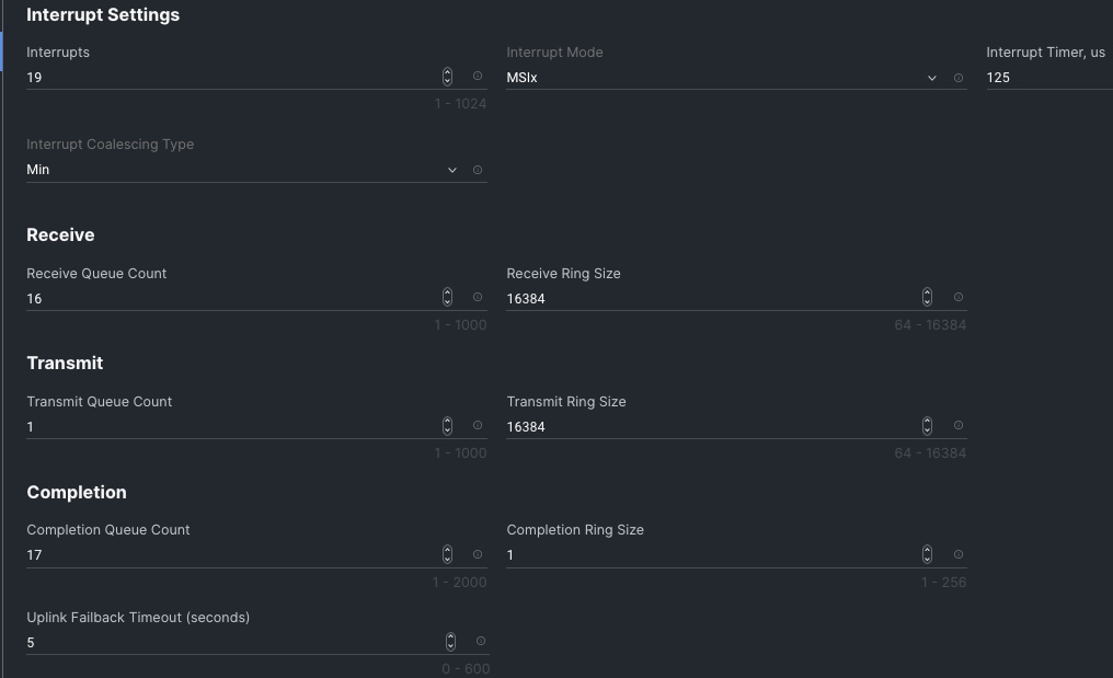
BIOS Policy
BIOS settings to be applied on the host will change based on the workload they run. The default BIOS settings promote power savings by reducing the operating speeds of processors and move the cores to deeper sleep states. These states need to be disabled for sustained high performance of database queries. For the server bios settings recommended for enterprise workloads are discussed in more detailed here:
Apart from the UCS policy settings previously mentioned, the remaining policies and configuration steps for deploying this FlexPod solution are the same as the ones used in the base infrastructure CVD described here: https://www.cisco.com/c/en/us/td/docs/unified_computing/ucs/UCS_CVDs/flexpod_ucs_xseries_e2e_ontap_manual_deploy.html
NetApp ONTAP Storage Configuration
This section provides the detailed steps for NetApp storage configuration specific to this solution.
NetApp AFF A400 Controllers
See the following section, NetApp Hardware Universe, for planning the physical location of the storage systems:
● Site Preparation
● System Connectivity Requirements
● Circuit Breaker, Power Outlet Balancing, System Cabinet Power Cord Plugs, and Console Pinout Requirements
● AFF Series Systems
The NetApp Hardware Universe (HWU) application provides supported hardware and software components for any specific ONTAP version. It also provides configuration information for all the NetApp storage appliances currently supported by ONTAP software and a table of component compatibilities.
To confirm that the hardware and software components that you would like to use are supported with the version of ONTAP that you plan to install, follow these steps at the NetApp Support site.
Procedure 1. Confirm hardware and software components
Step 1. Access the HWU application to view the System Configuration guides. Click the Products tab to select the Platforms menu to view the compatibility between different versions of the ONTAP software and the NetApp storage appliances with your desired specifications.
Step 2. Alternatively, to compare components by storage appliance, click the Utilities tab and select Compare Storage Systems.
Procedure 2. Controllers
Step 1. Follow the physical installation procedures for the controllers found here: https://docs.netapp.com/us-en/ontap-systems/index.html.
Disk Shelves
NetApp storage systems support a wide variety of disk shelves and disk drives. The complete list of disk shelves that are supported by the AFF A400 is available at the NetApp Support site.
When using SAS disk shelves with NetApp storage controllers, refer to: https://docs.netapp.com/us-en/ontap-systems/sas3/install-new-system.html for proper cabling guidelines.
When using NVMe drive shelves with NetApp storage controllers, refer to: https://docs.netapp.com/us-en/ontap-systems/ns224/hot-add-shelf.html for installation and servicing guidelines.
NetApp ONTAP 9.12.1
Procedure 1. Complete Configuration Worksheet
Step 1. Before running the setup script, complete the Cluster setup worksheet in the ONTAP 9 Documentation Center. You must have access to the NetApp Support site to open the cluster setup worksheet.
Procedure 2. Configure ONTAP Nodes
Step 1. Before running the setup script, review the configuration worksheets in the Software setup section of the ONTAP 9 Documentation Center to learn about configuring ONTAP.
Step 2. Refer to the Configure NetApp ONTAP Nodes section in the following deployment guide for initial nodes setup, cluster creation, and configuration steps: FlexPod Datacenter with End-to-End 100G, Cisco Intersight Managed Mode, VMware 7U3, and NetApp ONTAP 9.11
Figure 18 shows the Cluster Overview Dashboard in System Manager after cluster setup has been completed and all initial configuration steps have been performed according to the above document.
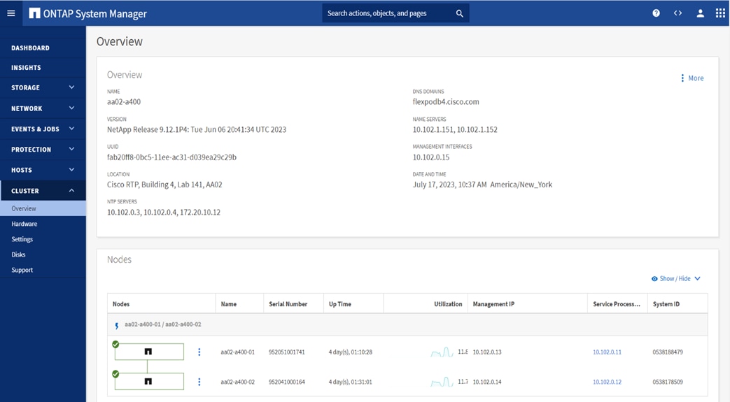
Note: NetApp ONTAP 9.10.1 and later for FAS/AFF storage systems uses a new file-based licensing solution to enable per-node NetApp ONTAP features. The new license key format is referred to as a NetApp License File, or NLF. For more information, refer to this URL: NetApp ONTAP 9.10.1 and later Licensing Overview - NetApp Knowledge Base.
The following procedures are the deployment steps to configure the NetApp ONTAP storage as required for the solution validation.
Procedure 1. Log into the Cluster
Step 1. Open SSH connection into either the Cluster IO or the host name
Step 2. Login with admin user with the password you provided earlier.
Procedure 2. Verify the Storage Failover
Step 1. Verify the status of the storage cluster.
storage failover show
Note: Both <st-node01> and < st-node02> must be capable of performing a takeover. Continue with step 2 if the nodes can perform takeover.
Step 2. Enable failover one of the two nodes if it was not completed during the installation.
storage failover modify -node <st-node01> -enabled true
Note: Enabling failover on one node enables it for both the nodes.
Step 3. Verify the HA status for two-node cluster.
Note: This step is not application for cluster with more than two nodes.
cluster ha show
Note: If HA is not configured, use the following commands. Only enable HA mode for two-node clusters. Do not run this command for clusters with more than two nodes because it causes problems with failover.
cluster ha modify -configured true
Do you want to continue? {y|n}: y
Procedure 3. Set Auto-Revert Parameter on Cluster Management Interface
Run the following command.
network interface modify -vserver <clustername> -lif cluster_mgmt_lif -auto-revert true
Note: A storage virtual machine (SVM) is referred to as a Vserver or vserver in the GUI and CLI.
Procedure 4. Zero All spare Disks
To zero all spare disks in the cluster, run the following command.
disk zerospares
Note: Advanced data Partitioning creates a root partition and two data partitions on each SSD drive in an AFF configuration. Disk auto-assign should have assigned one data partition to each node in an HA pair. If a different disk assignment is required, disk auto-assignment must be disabled on both nodes in the HA pair by running the disk option modify command. Spare partitions can then be moved from one node to another by running the disk removeowner and disk assign commands. Storage Virtual Machine (SVM) is referred to as a Vserver or vserver in the GUI and CLI.
Procedure 5. Create Manual provisioned Data Aggregates
An aggregate containing the root volume is created during the NetApp ONTAP cluster setup process. To manually create data aggregates, determine the aggregate name, the node on which to create it, and the number of disks it should contain. Options for disk class include solid-state, performance, capacity, array, and archive.
Step 1. To create data aggregates, run the following commands.
storage aggregate create -aggregate <aggr1_node01> -node <st-node01> -diskcount <num-disks> -diskclass solid-state
storage aggregate create -aggregate <aggr1_node02> -node <st-node02> -diskcount <num-disks> -diskclass solid-state
Step 2. Run the following command to get the disk class information from ONTAP storage system:
storage disk show -fields class
Note: You should have the minimum number of hot spare disks for the recommended hot spare disk partitions for your aggregate.
Note: For all-flash aggregates, you should have a minimum of one hot spare disk or disk partition. For non-flash homogenous aggregates, you should have a minimum of two hot spare disks or disk partitions. For Flash Pool aggregates, you should have a minimum of two hot spare disks or disk partitions for each disk type.
Note: In an AFF configuration with a small number of SSDs, you might want to create an aggregate with all, but one remaining disk (spare) assigned to the controller
Note: The aggregate cannot be created until disk zeroing completes. Run the storage aggregate show command to display the aggregate creation status. Do not proceed until both aggr1_node01 and aggr1_node02 are online.
Procedure 6. Remove the Default Broadcast Domains
By default, all network ports are included in separate default broadcast domain. Network ports used for data services (for example, e1a, e1b, and so on) should be removed from their default broadcast domain and that broadcast domain should be deleted)
Step 1. To perform this task, run the following commands:
network port broadcast-domain delete -broadcast-domain <Default-N> -ipspace Default
Note: Delete the Default broadcast domains with Network ports (Default-1, Default-2, and so on). This does not include Cluster ports and management ports.
Procedure 7. Disable Flow Control on 25/100GbE Data Ports
Step 1. Run the following command to configure the ports on node 01:
network port modify -node <st-node01> -port e1a,e1b -flowcontrol-admin none
Step 2. Run the following command to configure the ports on node 02:
network port modify -node <st-node02> -port e1a,e1b -flowcontrol-admin none
Note: Disable flow control only on ports that are used for data traffic.
Procedure 8. Enable Cisco Discovery Protocol
Step 1. To enable the Cisco Discovery Protocol (CDP) on the NetApp storage controllers, run the following command:
node run -node * options cdpd.enable on
Procedure 9. Enable Link-layer Discovery Protocol on all Ethernet Ports
Step 1. To enable LLDP on all ports of all nodes in the cluster, run the below command:
node run -node * options lldp.enable on
Procedure 10. Configure Timezone
Step 1. To configure time synchronization on the cluster, run the following command:
timezone -timezone <timezone>
Note: For example, in the eastern United States, the time zone is America/New_York.
Procedure 11. Create Management Broadcast Domain
Step 1. If the management interfaces are required to be on a separate VLAN, create a new broadcast domain for those inter-faces by running the following command:
network port broadcast-domain create -broadcast-domain SQL-MGMT -mtu 1500
Procedure 12. Create NFS Broadcast Domain
Step 1. To create an NFS data broadcast domain with a maximum transmission unit (MTU) of 9000, run the following command in NetApp ONTAP:
network port broadcast-domain create -broadcast-domain SQL-NFS -mtu 9000
Procedure 13. Create iSCSI Broadcast Domains
Step 1. To create an iSCSI-A and iSCSI-B data broadcast domain with a maximum transmission unit (MTU) of 9000, run the following commands in NetApp ONTAP:
network port broadcast-domain create -broadcast-domain SQL-iSCSI-A -mtu 9000
network port broadcast-domain create -broadcast-domain SQL-iSCSI-B -mtu 9000
Procedure 14. Create Interface Groups
Step 1. To create the LACP interface groups for the 100GbE data interfaces, run the following commands:
network port ifgrp create -node <st-node01> -ifgrp a0a -distr-func port -mode multimode_lacp
network port ifgrp add-port -node <st-node01> -ifgrp a0a -port e1a
network port ifgrp add-port -node <st-node01> -ifgrp a0a -port e1b
network port ifgrp create -node <st-node02> -ifgrp a0a -distr-func port -mode multimode_lacp
network port ifgrp add-port -node <st-node02> -ifgrp a0a -port e1a
network port ifgrp add-port -node <st-node02> -ifgrp a0a -port e1b
Procedure 15. Change MTU on Interface Groups
Step 1. To change the MTU size on the base interface-group ports before creating the VLAN ports, run the following commands:
network port modify –node <st-node01> -port a0a –mtu 9000
network port modify –node <st-node02> -port a0a –mtu 9000
Procedure 16. Create VLANs
Step 1. Create the management VLAN ports and add them to the management broadcast domain:
network port vlan create –node <st-node01> -vlan-name a0a-<sql-mgmt-vlan-id>
network port vlan create –node <st-node02> -vlan-name a0a-<sql-mgmt-vlan-id>
network port broadcast-domain add-ports -broadcast-domain SQL-MGMT -ports <st-node01>:a0a-<sql-mgmt-vlan-id>,<st-node02>:a0a-<sql-mgmt-vlan-id>
Step 2. Create the NFS VLAN ports and add them to the SQL-NFS broadcast domain:
network port vlan create –node <st-node01> -vlan-name a0a-<sql-nfs-vlan-id>
network port vlan create –node <st-node02> -vlan-name a0a-<sql-nfs-vlan-id>
network port broadcast-domain add-ports -broadcast-domain SQL-NFS -ports <st-node01>:a0a-<sql-nfs-vlan-id>,<st-node02>:a0a-<sql-nfs-vlan-id>
Step 3. Create iSCSI VLAN ports for the iSCSI LIFs on each storage controller and add them to the corresponding broadcast domains:
network port vlan create -node <st-node01> -vlan-name a0a-<sql-iscsi-a-vlan-id>
network port vlan create -node <st-node01> -vlan-name a0a-<sql-iscsi-b-vlan-id>
network port vlan create -node <st-node02> -vlan-name a0a-<sql-iscsi-a-vlan-id>
network port vlan create -node <st-node02> -vlan-name a0a-<sql-iscsi-b-vlan-id>
network port broadcast-domain add-ports -broadcast-domain SQL-iSCSI-A -ports <st-node01>:a0a-<sql-iscsi-a-vlan-id>
network port broadcast-domain add-ports -broadcast-domain SQL-iSCSI-B -ports <st-node01>:a0a-<sql-iscsi-b-vlan-id>
network port broadcast-domain add-ports -broadcast-domain SQL-iSCSI-A -ports <st-node02>:a0a-<sql-iscsi-a-vlan-id>
network port broadcast-domain add-ports -broadcast-domain SQL-iSCSI-B -ports <st-node02>:a0a-<sql-iscsi-b-vlan-id>
Procedure 17. Create Storage Virtual Machine (SVM) for SQL Workloads
SVM for SQL Server Databases serves as the logical storage system for Windows VMs and SQL Databases, called SQL-SVM.
Step 1. Run the vserver create command:
vserver create –vserver SQL-SVM –rootvolume SQL_SVM_root –aggregate aggr1_node01 –rootvolume-security-style unix
Step 2. Add the required data protocols to the SVM. In this solution, nfs and iscsi were used.
vserver add-protocols -protocols nfs,iscsi -vserver SQL-SVM
Step 3. Remove the unused data protocols from the SVM:
vserver remove-protocols –vserver SQL-SVM -protocols cifs,fcp
Note: It is recommended to remove CIFS or FCP protocols if the protocol is not in use.
Step 4. Add the two data aggregates to the SQL-SVM aggregate list for the NetApp ONTAP Tools:
vserver modify –vserver SQL-SVM –aggr-list <aggr1_node01>,<aggr1_node02>
Step 5. Enable and run the NFS protocol in the SQL-SVM:
vserver nfs create -vserver SQL-SVM -udp disabled -v3 enabled -v4.1 enabled -vstorage enabled
Note: If the NFS license was not installed during the cluster configuration, make sure to install the license before starting the NFS service.
Step 6. Verify that the NFS vstorage parameter for the NetApp NFS VAAI plug-in was enabled:
aa02-a400::> vserver nfs show -fields vstorage
vserver vstorage
------- --------
SQL-SVM enabled
Procedure 18. Vserver Protocol Verification
Step 1. Verify the required protocols are added to the SQL-SVM vserver:
aa02-a400::> vserver show-protocols -vserver SQL-SVM
Vserver: SQL-SVM
Protocols: nfs, iscsi
Step 2. If a protocol is not present, use the following command to add the protocol to the vserver:
vserver add-protocols -vserver <sql-svm> -protocols <iscsi or nfs>
Procedure 19. Create Load-Sharing Mirrors of SVM Root Volume
Step 1. Create a volume to be the load-sharing mirror of the SQL-SVM root volume on each node:
volume create –vserver SQL-SVM –volume SQL_SVM_root_m01 –aggregate <aggr1_node01> –size 1GB –type DP
volume create –vserver SQL-SVM –volume SQL_SVM_root_m02 –aggregate <aggr1_node02> –size 1GB –type DP
Step 2. Create a job schedule to update the root volume mirror relationships every 15 minutes:
job schedule interval create -name 15min -minutes 15
Step 3. Create the mirroring relationships:
snapmirror create –source-path SQL-SVM:SQL_SVM_root -destination-path SQL-SVM:SQL_SVM_root_m01 –type LS -schedule 15min
snapmirror create –source-path SQL-SVM:SQL_SVM_root –destination-path SQL-SVM:SQL_SVM_root_m02 –type LS -schedule 15min
Step 4. Initialize the mirroring relationship:
snapmirror initialize-ls-set –source-path SQL-SVM:SQL_SVM_root
Procedure 20. Create iSCSI Block Protocol Service
Step 1. Run the following command to create the iSCSI service. This command also starts the iSCSI service and sets the IQN for the SVM:
vserver iscsi create -vserver SQL-SVM -status-admin up
To verify:
aa02-a400::> vserver iscsi show
Target Target Status
Vserver Name Alias Admin
---------- -------------------------------- ---------------------------- ------
SQL-SVM iqn.1992-08.com.netapp:sn.a86f70fc0c7111eeac31d039ea29c29b:vs.3
SQL-SVM up
Note: If the iSCSI license was not installed during the cluster configuration, make sure to install the license before creating the iSCSI service.
Procedure 21. Set password for SVM vsadmin user and unlock the user
Step 1. Set a password for the SVM vsadmin user and unlock the user using the following commands:
security login password –username vsadmin –vserver SQL-SVM
Enter a new password: <password>
Enter it again: <password>
security login unlock –username vsadmin –vserver SQL-SVM
Procedure 22. Configure export policy rule
Step 1. Create a new rule for the SQL-SVM NFS subnet in the default export policy.
vserver export-policy rule create –vserver SQL-SVM -policyname default –ruleindex 1 –protocol nfs -clientmatch <sql-nfs-subnet-cidr> -rorule sys –rwrule sys -superuser sys –allow-suid true
Step 2. Assign the FlexPod export policy to the SQL-SVM root volume.
volume modify –vserver SQL-SVM –volume SQL_SVM_root –policy default
Procedure 23. Configure secure HTTPS access
Step 1. Increase the privilege level to access the certificate commands.
set -privilege diag
Do you want to continue? {y|n}: y
Step 2. A self-signed certificate is already in place. Verify the certificate and obtain parameters (for example, the <serial-number>) by running the following command:
security certificate show
Step 3. For each SVM shown, the certificate common name should match the DNS fully qualified domain name (FQDN) of the SVM. Delete the two default certificates and replace them with either self-signed certificates or certificates from a certificate authority (CA). To delete the default certificates, run the following commands:
security certificate delete -vserver SQL-SVM -common-name SQL-SVM -ca SQL-SVM -type server -serial <serial-number>
Note: Deleting expired certificates before creating new certificates is a best practice. Run the security certificate delete command to delete the expired certificates. In the following command, use TAB completion to select and delete each default certificate.
Step 4. To generate and install self-signed certificates, run the following commands as one-time commands. Generate a server certificate for the SQL-SVM and the cluster SVM. Use TAB completion to aid in the completion of these commands.
security certificate create -common-name <cert-common-name> -type server -size 2048 -country <cert-country> -state <cert-state> -locality <cert-locality> -organization <cert-org> -unit <cert-unit> -email-addr <cert-email> -expire-days <cert-days> -protocol SSL -hash-function SHA256 -vserver SQL-SVM
Step 5. To obtain the values for the parameters required in step 6 (<cert-ca> and <cert-serial>), run the security certificate show command.
Step 6. Enable each certificate that was just created by using the -server-enabled true and -client-enabled false parameters. Use TAB completion to aid in the completion of these commands.
security ssl modify -vserver <clustername> -server-enabled true -client-enabled false -ca <cert-ca> -serial <cert-serial> -common-name <cert-common-name>
Step 7. Disable HTTP cluster management access.
network interface service-policy remove-service -vserver <clustername> -policy default-management -service management-http
Note: It is normal for some of these commands to return an error message stating that the entry does not exist.
Note: The old command system services firewall policy delete is deprecated and may be removed in a future NetApp ONTAP release. So, use the command network interface service-policy remove-service instead.
Step 8. Change back to the normal admin privilege level and verify that the system logs are available in a web browser.
set –privilege admin
https://<node01-mgmt-ip>/spi
https://<node02-mgmt-ip>/spi
Procedure 24. Configure Storage for Microsoft SQL Server Databases
Application administrators need access to SQL-SVM to perform the following tasks:
● Provision storage for SQL Databases
● Backup, Restore, Clone, and Protect SQL Databases
Procedure 25. Create NetApp FlexVol Volumes for SQL Database and Logs
The following information is required to create a NetApp FlexVol volume:
● The volume name
● The volume size
● The aggregate on which the volume exists
In this solution, there are distributed SQL Server data and log volumes on two aggregates equally, to balance the performance and capacity utilization. For odd-numbered virtual machines, the data volumes reside on an aggregate tied to node-01, and for even-numbered virtual machines, the data volumes reside on the aggregate tied to node-02. Corresponding log volumes will be on the other controller or node. As you start the workload, make sure that you start with an even number of virtual machines, so that I/O will be evenly distributed.
Figure 19 shows a detailed storage layout scenario for the SQL Server database and log volumes.
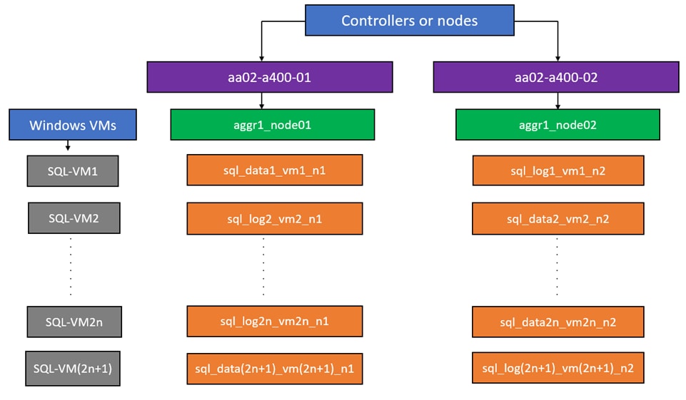
Step 1. To create SQL Server database and log volumes, run the following commands:
volume create -vserver SQL-SVM -volume sql_data1_vm1_n1 -aggregate aggr1_node01 -size 300GB -state online -policy default -junction-path /sql_data1_vm1_n1 -space-guarantee none -percent-snapshot-space 0
volume create -vserver SQL-SVM -volume sql_data2_vm2_n2 -aggregate aggr1_node02 -size 300GB -state online -policy default -junction-path /sql_data2_vm2_n2 -space-guarantee none -percent-snapshot-space 0
volume create -vserver SQL-SVM -volume sql_log1_vm1_n2 -aggregate aggr1_node02 -size 250GB -state online -policy default -junction-path /sql_log1_vm1_n2 -space-guarantee none -percent-snapshot-space 0
volume create -vserver SQL-SVM -volume sql_log2_vm2_n1 -aggregate aggr1_node01 -size 250GB -state online -policy default -junction-path /sql_log2_vm2_n1 -space-guarantee none -percent-snapshot-space 0
snapmirror update-ls-set -source-path SQL-SVM:SQL_SVM_root
Procedure 26. Create SQL Database and Log LUNs
Step 1. To create SQL Server database and log LUNs, run the following commands.
lun create -vserver SQL-SVM -volume sql_data1_vm1_n1 -lun sql-db1-vm1 -size 250GB -ostype windows -space-reserve disabled
lun create -vserver SQL-SVM -volume sql_data2_vm2_n2 -lun sql-db2-vm2 -size 250GB -ostype windows -space-reserve disabled
lun create -vserver SQL-SVM -volume sql_log1_vm1_n2 -lun sql-log1-vm1 -size 200GB -ostype windows -space-reserve disabled
lun create -vserver SQL-SVM -volume sql_log2_vm2_n1 -lun sql-log2-vm2 -size 200GB -ostype windows -space-reserve disabled
Note: In this solution, 12 Windows VMs were deployed. 12 database and 12 log volumes were created, one data and one log volume for each VM. LUNs are carved out of those volumes accordingly. For illustration purpose, only the volume and LUN creation steps for 2 Windows VMs are provided. You can configure data and log volumes depending on the number of VMs you have in your environments and also based on your application requirements.
Procedure 27. Configure Storage for VMware ESXi and Windows Virtual Machines
SVM for Windows Server 2022 VMs serves as a logical storage system for VMware ESXi datastores, called SQL-SVM. This SVM is authorized to perform the following tasks:
● Provision storage for ESXi datastores
● Backup and Restore VMs
Step 1. Create FlexVols for SQL Virtual Machine Datastores, by running the following commands:
volume create -vserver SQL-SVM -volume sql_datastore -aggregate aggr1_node02 -size 1TB -state online -policy default -junction-path /sql_datastore -space-guarantee none -percent-snapshot-space 0
Step 2. To create swap volumes for Windows VMs swap files, run the following command:
volume create -vserver SQL-SVM -volume sql_swap -aggregate aggr1_node01 -size 200GB -state online -policy default -junction-path /sql_swap -space-guarantee none -percent-snapshot-space 0 -snapshot-policy none
Step 3. To create a FlexVol for the boot LUNs of servers, run the following command:
volume create -vserver SQL-SVM -volume esxi_boot -aggregate aggr1_node01 -size 1TB -state online -policy default -space-guarantee none -percent-snapshot-space 0
Step 4. Create vCLS datastores to be used by the vSphere environment to host vSphere Cluster Services (vCLS) VMs using the command below:
volume create -vserver SQL-SVM -volume sql_vCLS -aggregate aggr1_node01 -size 100GB -state online -policy default -junction-path /sql_vCLS -space-guarantee none -percent-snapshot-space 0 -snapshot-policy none
Step 5. Update set of load-sharing mirrors using the command below:
snapmirror update-ls-set -source-path SQL-SVM:SQL_SVM_root
Note: If you are going to setup and use SnapCenter to backup the sql_datastore volume, add “-snapshot-policy none” to the end of the volume create command for the sql_datastore volume.
Procedure 28. Disable Volume Efficiency on swap volume
Step 1. On NetApp AFF systems, deduplication is enabled by default. To disable the efficiency policy on the sql_swap volume, run the following command:
volume efficiency off –vserver SQL-SVM –volume sql_swap
Procedure 29. Create NFS LIFs
Step 1. Create two NFS LIFs (one on each node), by running the following commands:
network interface create -vserver SQL-SVM -lif nfs-lif-01 -service-policy default-data-files -home-node <st-node01> -home-port a0a-<sql-nfs-vlan-id> –address <node01-nfs-lif-01-ip> -netmask <node01-nfs-lif-01-mask> -status-admin up –failover-policy broadcast-domain-wide –auto-revert true
network interface create -vserver SQL-SVM -lif nfs-lif-02 -service-policy default-data-files -home-node <st-node02> -home-port a0a-<sql-nfs-vlan-id> –address <node02-nfs-lif-02-ip> -netmask <node02-nfs-lif-02-mask> -status-admin up –failover-policy broadcast-domain-wide –auto-revert true
To verify:
aa02-a400::> network interface show -vserver SQL-SVM -service-policy default-data-files
Logical Status Network Current Current Is
Vserver Interface Admin/Oper Address/Mask Node Port Home
----------- ---------- ---------- ------------------ ------------- ------- ----
SQL-SVM
nfs-lif-01 up/up 192.168.53.13/24 aa02-a400-01 a0a-3053 true
nfs-lif-02 up/up 192.168.53.14/24 aa02-a400-02 a0a-3053 true
2 entries were displayed.
Note: For the tasks using the network interface create command, the -role and -firewall-policy parameters have been deprecated and may be removed in a future version of NetApp ONTAP. Use the -service-policy parameter instead.
Procedure 30. Create iSCSI LIFs
Step 1. Create four iSCSI LIFs (two on each node), by running the following commands:
network interface create -vserver SQL-SVM -lif iscsi-lif-01a -service-policy default-data-iscsi -home-node <st-node01> -home-port a0a-<sql-iscsi-a-vlan-id> -address <st-node01-sql-iscsi-a–ip> -netmask <sql-iscsi-a-mask> -status-admin up
network interface create -vserver SQL-SVM -lif iscsi-lif-01b -service-policy default-data-iscsi -home-node <st-node01> -home-port a0a-<sql-iscsi-b-vlan-id> -address <st-node01-sql-iscsi-b–ip> -netmask <sql-iscsi-b-mask> –status-admin up
network interface create -vserver SQL-SVM -lif iscsi-lif-02a -service-policy default-data-iscsi -home-node <st-node02> -home-port a0a-<sql-iscsi-a-vlan-id> -address <st-node02-sql-iscsi-a–ip> -netmask <sql-iscsi-a-mask> –status-admin up
network interface create -vserver SQL-SVM -lif iscsi-lif-02b -service-policy default-data-iscsi -home-node <st-node02> -home-port a0a-<sql-iscsi-b-vlan-id> -address <st-node02-sql-iscsi-b–ip> -netmask <sql-iscsi-b-mask> –status-admin up
To verify:
aa02-a400::> network interface show -vserver SQL-SVM -service-policy default-data-iscsi
Logical Status Network Current Current Is
Vserver Interface Admin/Oper Address/Mask Node Port Home
----------- ---------- ---------- ------------------ ------------- ------- ------
SQL-SVM
iscsi-lif-01a
up/up 192.168.13.13/24 aa02-a400-01 a0a-3013
true
iscsi-lif-01b
up/up 192.168.23.13/24 aa02-a400-01 a0a-3023
true
iscsi-lif-02a
up/up 192.168.13.14/24 aa02-a400-02 a0a-3013
true
iscsi-lif-02b
up/up 192.168.23.14/24 aa02-a400-02 a0a-3023
true
4 entries were displayed.
Procedure 31. Create SVM management LIF (Add SQL-SVM Administrator)
Step 1. Run the following commands:
network interface create –vserver SQL-SVM –lif svm-mgmt -service-policy default-management –home-node <st-node01> -home-port a0a-<sql-mgmt-vlan-id> –address <svm-mgmt-ip> -netmask <svm-mgmt-mask> -status-admin up -failover-policy broadcast-domain-wide –auto-revert true
Step 2. Create a default route that enables the SVM management interface to reach the outside world.
network route create –vserver SQL-SVM -destination 0.0.0.0/0 –gateway <svm-mgmt-gateway>
To verify:
aa02-a400::> network route show -vserver SQL-SVM
Vserver Destination Gateway Metric
------------------- --------------- --------------- ------
SQL-SVM
0.0.0.0/0 10.102.3.254 20
Note: A cluster serves data through at least one and possibly several SVMs. These steps have been created for a single data SVM. You can create additional SVMs depending on your requirement.
Procedure 32. Configure AutoSupport
Step 1. NetApp AutoSupport sends support summary information to NetApp through HTTPS. To configure AutoSupport using command-line interface, run the following command:
system node autosupport modify -node * -state enable –mail-hosts <mailhost> -from <from-email-address> -to <to-email-address> -transport https -support enable
NetApp ONTAP Boot Storage Setup
This configuration requires information from both the UCS server profiles and NetApp storage system. After creating the boot LUNs, initiator groups, and appropriate mappings between the two, UCS server profiles will be able to see the boot disks hosted on NetApp controllers.
Procedure 1. Create Boot Luns
Step 1. Run the following commands on the NetApp Cluster Management Console to create iSCSI boot LUNs for the ESXi servers:
lun create -vserver SQL-SVM -path /vol/esxi_boot/aa02-sql-esxi-1-ISCSI -size 128GB -ostype vmware -space-reserve disabled
lun create -vserver SQL-SVM -path /vol/esxi_boot/aa02-sql-esxi-2-ISCSI -size 128GB -ostype vmware -space-reserve disabled
lun create -vserver SQL-SVM -path /vol/esxi_boot/aa02-sql-esxi-3-ISCSI -size 128GB -ostype vmware -space-reserve disabled
lun create -vserver SQL-SVM -path /vol/esxi_boot/aa02-sql-esxi-4-ISCSI -size 128GB -ostype vmware -space-reserve disabled
Procedure 2. Create Initiator Groups
Obtain the IQNs for UCS Server Profiles
Step 1. From the Cisco Intersight GUI, go to: Configure > Pools > [IQN Pool Name] > Usage and find the IQN information for various ESXi servers:
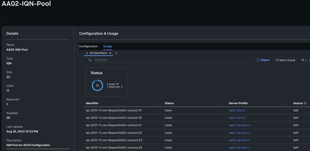
Procedure 3. Create Initiator Groups for iSCSI Storage Access
Step 1. Run the following commands to create iSCSI initiator groups (igroups):
lun igroup create –vserver SQL-SVM –igroup aa02-sql-esxi-1-ISCSI –protocol iscsi –ostype vmware -initiator iqn.2010-11.com.flexpod:aa02-ucshost:24
lun igroup create –vserver SQL-SVM –igroup aa02-sql-esxi-2-ISCSI –protocol iscsi –ostype vmware –initiator iqn.2010-11.com.flexpod:aa02-ucshost:21
lun igroup create –vserver SQL-SVM –igroup aa02-sql-esxi-3-ISCSI –protocol iscsi –ostype vmware -initiator iqn.2010-11.com.flexpod:aa02-ucshost:23
lun igroup create –vserver SQL-SVM –igroup aa02-sql-esxi-4-ISCSI –protocol iscsi –ostype vmware –initiator iqn.2010-11.com.flexpod:aa02-ucshost:22
Step 2. To view and verify the igroups just created, use the following command:
aa02-a400::> lun igroup show -vserver SQL-SVM -protocol iscsi
Vserver Igroup Protocol OS Type Initiators
--------- ------------ -------- -------- ------------------------------------
SQL-SVM aa02-sql-esxi-1-ISCSI
iscsi vmware iqn.2010-11.com.flexpod:aa02-ucshost:24
SQL-SVM aa02-sql-esxi-2-ISCSI
iscsi vmware iqn.2010-11.com.flexpod:aa02-ucshost:21
SQL-SVM aa02-sql-esxi-3-ISCSI
iscsi vmware iqn.2010-11.com.flexpod:aa02-ucshost:23
SQL-SVM aa02-sql-esxi-4-ISCSI
iscsi vmware iqn.2010-11.com.flexpod:aa02-ucshost:22
4 entries were displayed.
Step 3. (Optional) To access a common datastore from all the hosts, a common igroup for all the servers can be created as follows:
lun igroup create –vserver SQL-SVM –igroup SQL-MGMT-Hosts –protocol iscsi –ostype vmware –initiator <vm-host-sql-01-iqn >, <vm-host-sql-02-iqn >, <vm-host-sql-03-iqn >, <vm-host-sql-04-iqn>
Procedure 4. Map Boot LUNs to ISCSI igroups
Step 1. Map the boot LUNs to ISCSI igroups, by entering the following commands on NetApp cluster management console:
lun mapping create –vserver SQL-SVM –path /vol/esxi_boot/aa02-sql-esxi-1-ISCSI –igroup aa02-sql-esxi-1-ISCSI –lun-id 0
lun mapping create –vserver SQL-SVM –path /vol/esxi_boot/aa02-sql-esxi-2-ISCSI –igroup aa02-sql-esxi-2-ISCSI –lun-id 0
lun mapping create –vserver SQL-SVM –path /vol/esxi_boot/aa02-sql-esxi-3-ISCSI –igroup aa02-sql-esxi-3-ISCSI –lun-id 0
lun mapping create –vserver SQL-SVM –path /vol/esxi_boot/aa02-sql-esxi-4-ISCSI –igroup aa02-sql-esxi-4-ISCSI –lun-id 0
Step 2. To verify the mapping was setup correctly, issue the following command:
aa02-a400::> lun mapping show -vserver SQL-SVM -protocol iscsi
Vserver Path Igroup LUN ID Protocol
---------- ---------------------------------------- ------- ------ --------
SQL-SVM /vol/esxi_boot/aa02-sql-esxi-1-ISCSI aa02-sql-esxi-1-ISCSI
0 iscsi
SQL-SVM /vol/esxi_boot/aa02-sql-esxi-2-ISCSI aa02-sql-esxi-2-ISCSI
0 iscsi
SQL-SVM /vol/esxi_boot/aa02-sql-esxi-3-ISCSI aa02-sql-esxi-3-ISCSI
0 iscsi
SQL-SVM /vol/esxi_boot/aa02-sql-esxi-4-ISCSI aa02-sql-esxi-4-ISCSI
0 iscsi
4 entries were displayed.
Finalize the NetApp ONTAP Storage Configuration
Make the following configuration changes to finalize the NetApp controller configuration.
Procedure 1. Configure DNS for SQL SVM
Step 1. To configure DNS for the SQL-SVM, run the following command:
dns create -vserver SQL-SVM -domains flexpodb4.cisco.com -nameservers 10.102.1.151,10.102.1.152
Procedure 2. Delete the residual default broadcast domains with ifgroups (Applicable for 2-node cluster only)
Step 1. To delete the residual default broadcast domains that are not in use, run the following commands:
broadcast-domain delete -broadcast-domain Default-1
broadcast-domain delete -broadcast-domain Default-2
Procedure 3. Test AutoSupport
Step 1. To test the AutoSupport configuration by sending a message from all nodes of the cluster, run the following command:
autosupport invoke -node * -type all -message “FlexPod ONTAP dstorage configuration for SQL workloads completed”
FlexPod Management Tools Setup
This section provides information about how to configure NetApp management tools such as ONTAP tools, Active IQ Unified Manager, and SnapCenter that are used and validated in this solution.
NetApp ONTAP Tools 9.12 Deployment
Refer to the NetApp ONTAP Tools Deployment section of the FlexPod Infrastructure CVD, for the ONTAP tools installation and configuration steps.
Note: NetApp ONTAP Tools for VMware vSphere version 9.12 was used in this solution validation to provision storage for VMware ESXi datastores for virtual machines.
Some important points to remember while deploying ONTAP tools 9.12:
● Application user password and Derby database password: For security reasons, it is recommended that the password length is eight to thirty characters long and contains a minimum of one upper, one lower, one digit, and one special character. Password expires after 90 days.
● From ONTAP tools 9.12 release onwards all ONTAP storage systems communication happens through certificate based authentication.
For detailed information about NetApp ONTAP tools for VMware vSphere, go to: https://docs.netapp.com/us-en/ontap-tools-vmware-vsphere/index.html.
Active IQ Unified Manager 9.12 Installation
Refer to the Active IQ Unified Manager section of the FlexPod Infrastructure CVD, for the Active IQ Unified Manager deployment and configuration steps.
You can also refer to the Active IQ Unified Manager documentation for detailed prerequisites and deployment steps.
NetApp SnapCenter 4.8 Deployment
NetApp SnapCenter 4.8 was used in this solution validation for following use cases:
● Backup and restore of VMware virtual machines.
● Backup, restore, protection, and cloning of SQL Databases.
● Storage provisioning for SQL databases and logs.
Refer to the SnapCenter Plug-in for VMware vSphere 4.8 documentation, for prerequisites and deployment steps. Installation and configuration of the SnapCenter Plug-in for VMWare vSphere is required for the VM Backup/Restore. For more details, refer to the SnapCenter software documentation.
You can follow the steps under the Add storage section of the SnapCenter VMware plugin documentation to add ONTAP storage clusters or storage VMs.
Note: The SnapCenter plug-in for Microsoft SQL Server is required to protect SQL Server databases using SnapCenter. The SnapCenter plug-in for Microsoft SQL Server and SnapCenter plug-in for Microsoft Windows are both required on each Windows virtual machine running SQL Server.
Refer to the Installation guide for SnapCenter Plug-in for Microsoft SQL Server, for prerequisites and installation steps. When a Host (Windows VM) running SQL Server is added to SnapCenter, SnapCenter Plug-in for Microsoft SQL Server and SnapCenter Plug-in for Microsoft Windows are installed on the VM. Table 5 lists the port requirements.
| Port |
Requirement |
| 443 (HTTPS) |
Used for communication between the SnapCenter Server and SVM management LIF of ONTAP. |
| 8146 (HTTPS) |
Used for communication between the SnapCenter client (the SnapCenter user) and the SnapCenter Server. Also used for communication from the plug-in hosts to the SnapCenter Server. |
| 135, 445 (TCP) on Windows plug-in hosts |
The ports are used for communication between the SnapCenter Server and the host on which the plug-in is being installed. To push plug-in package binaries to Windows plug-in hosts, the ports must be open only on the plug-in host, and they can be closed after installation. |
| 8145 (HTTPS), bidirectional |
The port is used for communication between SMCore and hosts where the SnapCenter plugins package for Windows is installed. |
| 1433 (TCP) |
Port for SQL Server management access. |
Table 6 lists the licenses which are required to be installed on the ONTAP storage system to backup and restore SQL Server databases.
Table 6. SnapCenter Plug-in for Microsoft SQL Server License Requirements
| Product |
License Requirements |
| ONTAP Primary |
For SnapCenter Plug-in for of SQL Server, following licenses should be installed: One of these: SnapMirror or SnapVault (for secondary data protection regardless of the type of relationship) SnapManager Suite: used for SnapCenter functionality SnapRestore: used for restore operations FlexClone: used for mount and attach operations |
| ONTAP Secondary Destinations |
To protect SQL databases on secondary storage: FlexClone: used for mount and attach operations |
VMware vSphere ESXi Configuration
This section describes the VMWare ESXi host-specific configurations required on each ESXi host.
Update VIC Drivers
It is recommended to use the latest VIC drivers for the specific vSphere ESXi hypervisor. For the current VIC driver versions, go to: Cisco UCS Hardware & Software Interoperability Matrix.
At the time of testing of this solution, the following are the versions of the VIC drivers that were used from the Cisco custom image for VMware vSphere 8.0.
Note: It is recommended to upgrade to the latest version that is available.
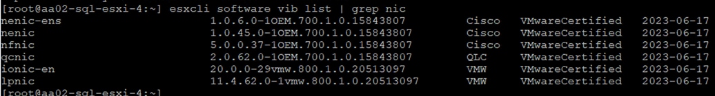
ESXi has been heavily tuned for driving high I/O throughput efficiently by utilizing fewer CPU cycles and conserving power. Hence the Power setting on the ESXi host is set to “Balanced.” However, for critical database deployments, it is recommended to set the power setting to “High Performance.” Selecting “High Performance” causes the physical cores to run at higher frequencies and thereby it will have positive impact on the database performance.
ESXi Host Networking Configuration
This section provides information about the ESXi host network configuration used for this FlexPod system. Table 7 lists the network configuration used for this solution.
Table 7. ESXi Host Network Configuration
| Switch Name |
Details |
| vSwitch0 |
Purpose: For managing and accessing ESXi hosts and for Out Of Band access UCS vNICs: 00-vSwitch0-A and 01-vSwitch0-B ESXi Physical Adapters: vmnic0 and vmnic1 MTU: 1500 PortGroups:
●
Management Network (Native VLAN: 1023): For managing and accessing ESXi hosts
●
Physical Adapter Configuration: vmnic0(active) and vmnic1 (active)
●
vmkernel: vmk0
●
OOB-MGMT-Network (VLAN: 1020): For OOB access
●
Physical Adapter Configuration: vmnic0(active) and vmnic1 (active)
|
| SQL-vDS0 |
Purpose: For SQL VM management traffic, NFS and vMotion UCS vNICs: 02-vDS0-A and 03-vDS0-B ESXi Physical Adapters: vmnic2 (UPLINK 1) and vmnic3 (UPLINK 2) MTU: 9000 PortGroups:
●
SQL-MGMT (VLAN: 1023): For SQL VM management traffics
●
Physical Adapter Configuration: vmnic2(active ) and vmnic3 (active)
●
SQL-NFS (VLAN: 3053): For NFS datastore access
●
Physical Adapter Configuration: vmnic2(active) and vmnic3 (active)
●
vmkernel: vmk3, with MTU 9000
●
SQL-vMotion (VLAN: 3000): For vMotion traffic
●
Physical Adapter Configuration: vmnic2(standby) and vmnic3 (active)
●
vmkernel: vmk4, with MTU 9000
|
| SQL-iSCSI-vDS |
Purpose: For storage traffic over Fabric A and B UCS vNICs: 04-iSCSI-A and 05-iSCSI-B ESXi Physical Adapters: vmnic4 (UPLINK 1) and vmnic5 (UPLINK 2) MTU: 9000 PortGroups:
●
SQL-iSCSI-A (NATIVE VLAN: 3013): For storage traffic over Fabric A
●
Physical Adapter Configuration: vmnic4 (active ) and vmnic5 (unused)
●
vmkernel: vmk1 with MTU 9000
●
SQL-iSCSI-B (VLAN: 3023): For storage traffic over Fabric B
●
Physical Adapter Configuration: vmnic4 (unused) and vmnic5 (active)
●
vmkernel: vmk2 with MTU 9000
|
Figure 21 shows the logical network diagram of the ESXi cluster. It depicts the all the port groups and VMKernel adapters of the ESXi host described in Table 7.
Provision VMware ESXi Datastores for Windows Virtual Machines using NetApp ONTAP Tools
Procedure 1. Provision ESXi Datastore for Windows Virtual Machines from vCenter ONTAP tools plug-in
Step 1. From the vCenter console, click Menu > NetApp ONTAP tools.
Step 2. From the NetApp ONTAP tools Home page, click Overview.
Step 3. In the Getting Started tab, click Provision.
Step 4. Click Browse to select the destination to provision the datastore.
Step 5. Select the type as NFS and Enter the datastore name (for example, SQL_NFS_DS_01).
Step 6. Provide the size of the datastore and the NFS Protocol.
Step 7. Check the storage capability profile and click NEXT.
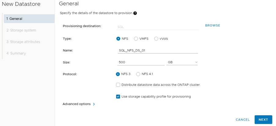
Step 8. Select the desired Storage Capability Profile, cluster name and the desired SVM to create the datastore. In this example, the SQL-SVM is selected. Click NEXT.

Step 9. Select the aggregate name and click NEXT.
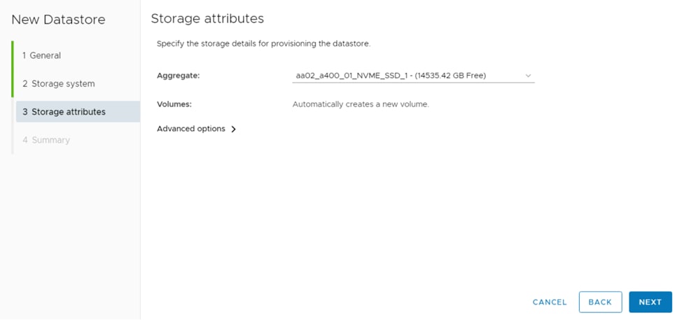
Step 10. Review the Summary and click FINISH.
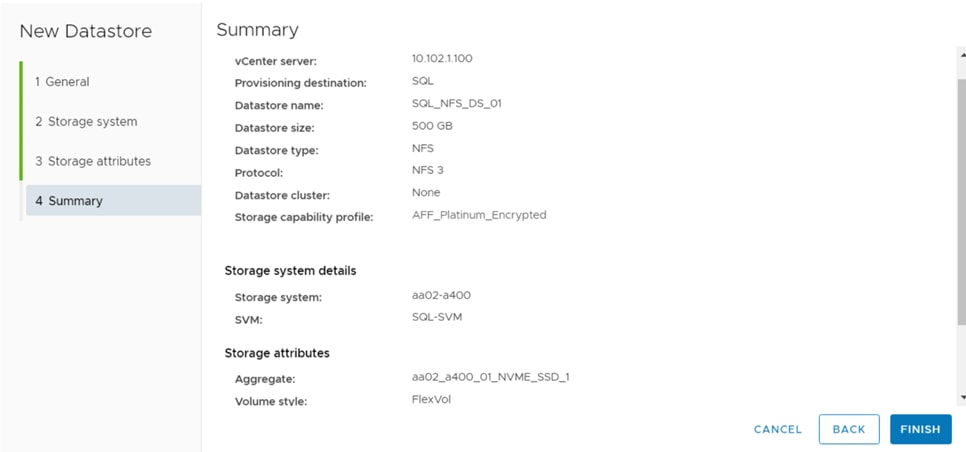
Step 11. The datastore is created and mounted on the hosts in the cluster. Click Refresh from the vSphere Web Client to see the newly created datastore. Check the datastore configuration in the datastore view of vCenter.
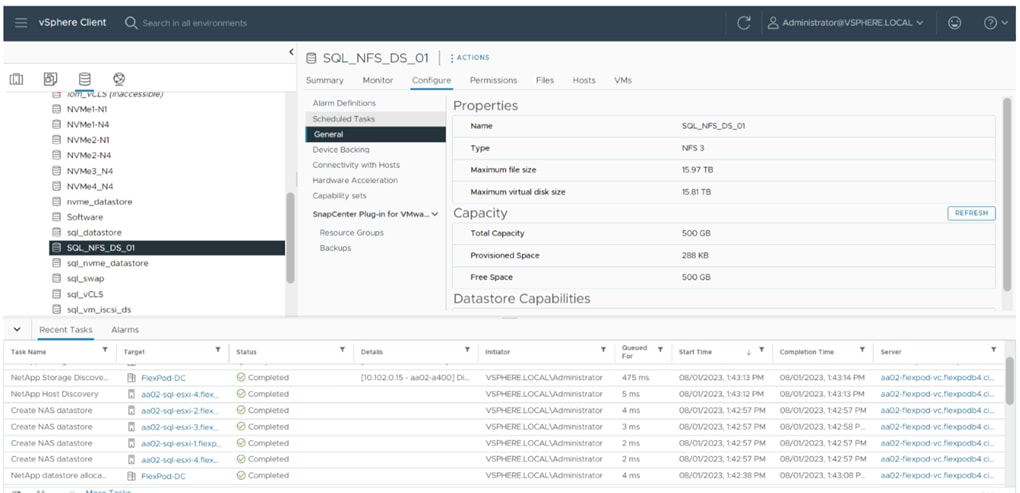
Step 12. Repeat steps 1 through 10 for one more datastore and select a different aggregate to provision. You should distribute the virtual machines on two datastores residing on different aggregates, so the storage capacity and performance are balanced.
Note: To provision the iSCSI datastore using ONTAP tools, for the Datastore type select VMFS and for Protocol select iSCSI.
Virtual Machine Configuration for Hosting SQL Server Database
This section describes best practices and recommendations for creating and deploying SQL Server virtual machines on the FlexPod system.
SQL Server database transactions are usually CPU and memory intensive. In heavily OLTP database systems, you should reserve all the memory allocated to the SQL Server virtual machines as shown in Figure 22. This approach helps ensure that the memory assigned to the SQL Server virtual machines is committed, and it eliminates the possibility that ballooning and swapping will occur.
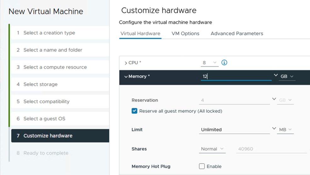
The network adapter of type VMXNET3 should be used for SQL Server virtual machine. VMXNET 3 is the latest generation of para virtualized NICs designed for performance. It offers several advanced features, including multiple-queue support, receive-side scaling, IPv4/IPv6 offloads, and message-signaled interrupt (MSI) and MSI-X interrupt delivery.
In this solution, each SQL Server virtual machine is configured with three network adapters, with VMXNET3 as the adapter type. One adapter is connected to the SQL-MGMT port group for virtual machine management and SQL Server access, and the second and third network adapters are connected to the SQL-iSCSI-A and SQL-iSCSI-B port groups respectively. These adapters are used for direct NetApp storage access using the Microsoft software iSCSI initiator over Fabrics A and B respectively. Figure 23 shows the SQL Server virtual machine configured with three adapters.
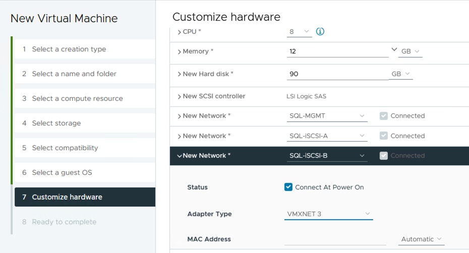
Guest Operating System Installation and Configuration for NetApp Storage access over iSCSI
This section provides configuration recommendations for the Windows guest operating system for hosting SQL Server databases. For a detailed step-by-step process for installing the Windows Server 2022 guest operating system in the virtual machine, refer to the VMware documentation.
When the Windows guest operating system is installed in the virtual machine, you also should install the VMware tools as explained here.
The default power policy option in Windows Server 2022 is Balanced. For SQL Server database deployments, you should set the power management option to High Performance for optimal database performance, as shown in Figure 24.
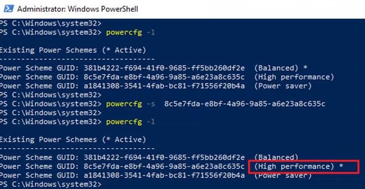
Procedure 1. Add a Guest Virtual Machine to the Domain
Note: You should change the default Windows guest virtual machine name and join the virtual machine to the domain before you proceed with the storage configuration for the guest virtual machine. For detailed instructions about how to change the guest name and join the guest, click here.
Step 1. Using the server manager, enable the Remote Desktop feature to remotely manage the guest virtual machine and turn off the firewalls in the guest virtual machine.
Figure 25 shows the final configuration of a sample VM (SQL-VM1) after it has joined to the flexpodb4.cisco.com domain, enabling Remote Desktop and turning off the firewall settings, and corresponding IP addresses of the management and iSCSI storage interfaces IP addresses.
Note: The storage adapters which were created from SQL-iSCSI-A and SQL-iSCSI-B port groups have been changed to iSCSIA and iSCSIB.
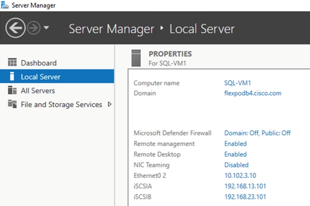
Storage Configuration in the SQL Virtual Machine
This section describes the guest configuration for jumbo frames, the installation and configuration of multipath software, and the iSCSI initiator configuration for connecting NetApp AFF A400 storage LUNs directly from the SQL Server virtual machines.
Procedure 1. Enable Jumbo Frames on Storage Network Interfaces
Step 1. Enabling jumbo frames for storage traffic provides better I/O performance for SQL Server databases. In the SQL Server guest virtual machine, make sure that jumbo frames are set to 9000 on the Ethernet adapter used for NetApp storage connectivity as shown in following figure.
Step 2. After enabling jumbo frames, make sure the virtual machine can reach the storage with the maximum packet size without fragmenting the packets, as shown in Figure 26.
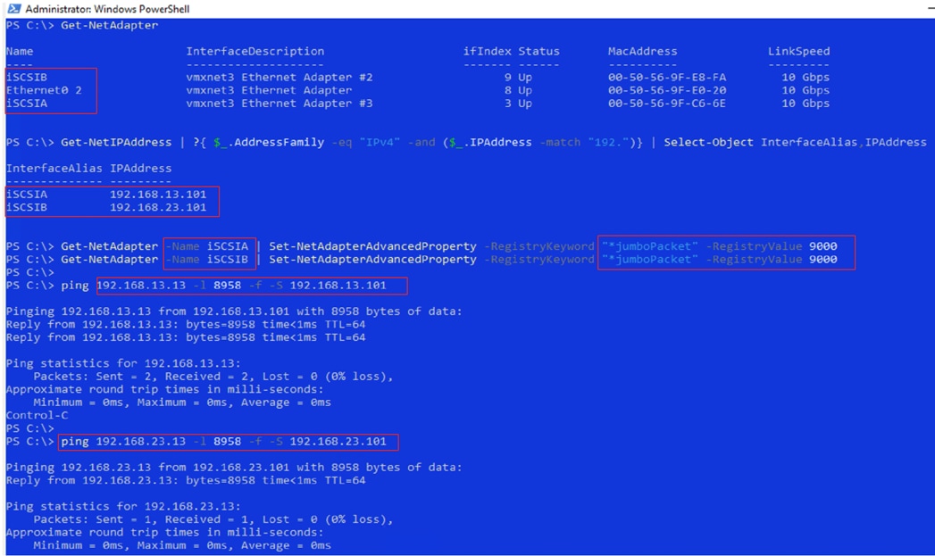
Procedure 2. Configure multipath software
Note: NetApp recommends using Windows native multipath drivers to manage storage connections in the Windows Server 2022 guest virtual machine. Figure 27 shows the installation of the multipath I/O feature using PowerShell.
Step 1. After installing this feature, enable Microsoft Device Specific Module (MSDSM) to automatically claim SAN disks for Microsoft Multipath I/O (MPIO) for the iSCSI bus type.
Step 2. Restart the virtual machine to make the changes take effect.
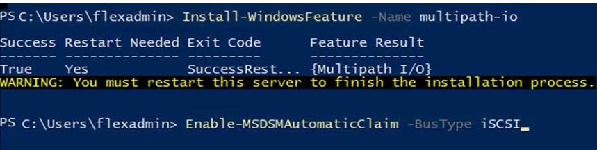
Procedure 3. Install the NetApp Windows Unified Host Utilities on the virtual machine
Step 1. Download NetApp Host Utilities Version 7.2 for Windows from this link:
https://mysupport.netapp.com/site/products/all/details/hostutilities/downloads-tab/download/61343/7.2/downloads
Step 2. Unzip the file and run the executable file. The NetApp Windows Unified Host Utilities setup wizard is launched. Click Next.
Step 3. Click Yes, install support for Multipath I/O, and click Next.
Step 4. Accept the default destination folder and click Next.
Step 5. Click Next and then click Install to start the installation of the host utilities.
Step 6. After the installation is complete, click Finish and restart the virtual machine.
Step 7. After the virtual machine is restarted, verify that appropriate device drivers are added in the MPIO utility as shown below:
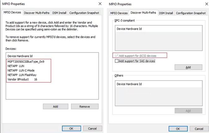
Procedure 4. Configure iSCSI Software Initiator
This procedure provides the steps for configuring the in-guest iSCSI initiator for virtual machines to directly access the NetApp storage LUNs.
Step 1. Start the Microsoft iSCSI initiator service and set it to start automatically as shown in following screenshot. Find the virtual machine initiator ID and make a note of it, because you will need it to grant the NetApp storage LUN access to the guest virtual machine.
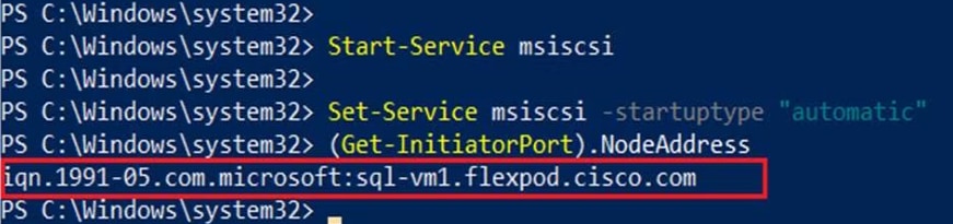
Step 2. Open the NetApp ONTAP System Manager and create an initiator group using the iSCSI initiator name previously noted. After the initiator group for the virtual machines is created, assign the required LUNs to the initiator group. To assign a LUN to an initiator group, you need to edit the LUN and select the required initiator group. For instance, sql_db1_vm1 LUN is assigned to the SQL-VM1 initiator group in the following screenshot.
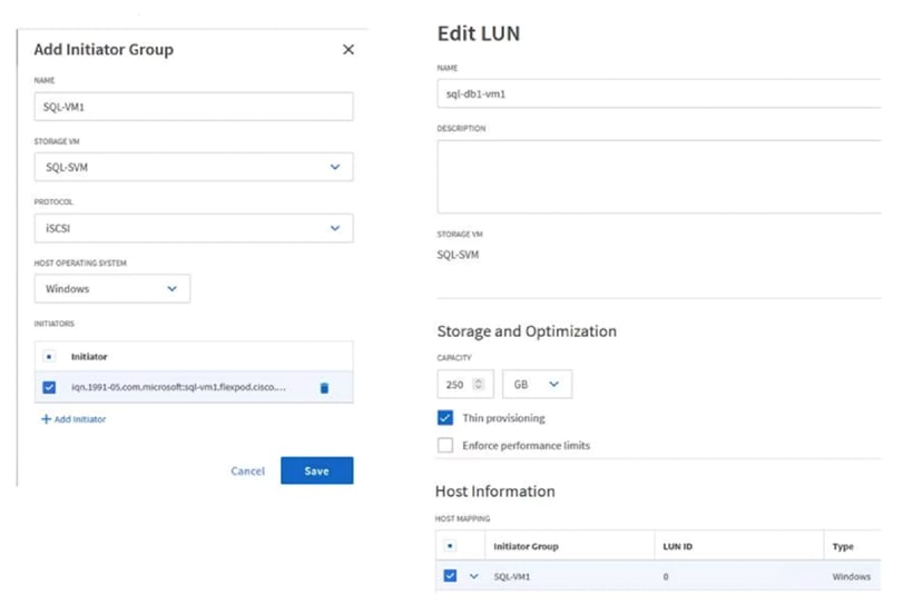
Step 3. Run the following PowerShell commands on the guest virtual machine to establish connections to the NetApp target iSCSI IP addresses. For each virtual machine, you need to replace InitiatorPortalAddress with the appropriate guest iSCSI IP address:
New-IscsiTargetPortal -TargetPortalAddress 192.168.13.13 -InitiatorPortalAddress 192.168.13.101
New-IscsiTargetPortal -TargetPortalAddress 192.168.13.14 -InitiatorPortalAddress 192.168.13.101
New-IscsiTargetPortal -TargetPortalAddress 192.168.23.13 -InitiatorPortalAddress 192.168.23.101
New-IscsiTargetPortal -TargetPortalAddress 192.168.23.14 -InitiatorPortalAddress 192.168.23.101
Step 4. Connect to the NetApp targets using the following PowerShell commands from the SQL Guest VM:
$target = Get-IscsiTarget
Connect-IscsiTarget -TargetPortalAddress 192.168.13.13 -InitiatorPortalAddress 192.168.13.101 -NodeAddress $target.NodeAddress -IsMultipathEnabled $true -IsPersistent $true
Connect-IscsiTarget -TargetPortalAddress 192.168.13.14 -InitiatorPortalAddress 192.168.13.101 -NodeAddress $target.NodeAddress -IsMultipathEnabled $true -IsPersistent $true
Connect-IscsiTarget -TargetPortalAddress 192.168.23.13 -InitiatorPortalAddress 192.168.23.101 -NodeAddress $target.NodeAddress -IsMultipathEnabled $true -IsPersistent $true
Connect-IscsiTarget -TargetPortalAddress 192.168.23.14 -InitiatorPortalAddress 192.168.23.101 -NodeAddress $target.NodeAddress -IsMultipathEnabled $true -IsPersistent $true
Step 5. Verify the connections as shown following screenshot. You should see four iSCSI connections established to the NetApp storage.
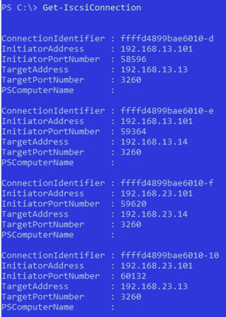
Step 6. Open Disk Management and initialize and format the disks with the NTFS file system and a 64-KB allocation unit size. Under Disk Management, right-click the disk and select Properties.
Step 7. In the NetApp LUN C-Mode Multi-Path Disk Device Properties dialog box, click the MPIO tab. You should see four storage connections being established: two being active and optimized and the other two being active and unoptimized. These represent the path states defined by the SCSI Asymmetric Logical Unit Access (ALUA) protocol, with the active and optimized path being the path to the primary storage controller for the LUN, and the active and unoptimized being the path to the high-availability partner controller. The following screenshot shows the virtual machine using the Disk Management tool.
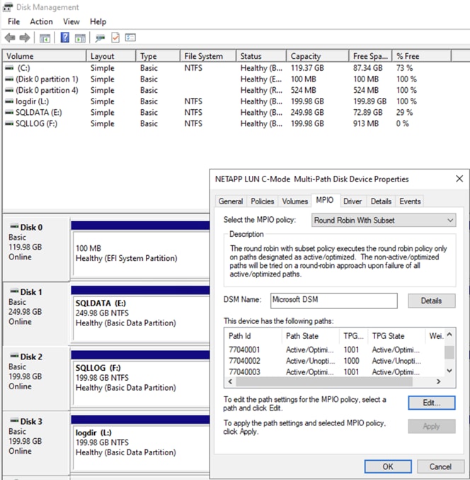
Microsoft SQL Server Installation and Configuration
Many recommendations and best-practices guides are available for most SQL Server settings. But the relevance of these recommendations varies from one database deployment to another. Therefore, you should thoroughly test and validate the critical settings and determine whether to implement the specific database environment. The following sections describe some of the important SQL Server installation and configuration settings that have been used and tested on the FlexPod system. The rest of the SQL Server options are kept at their default settings and used for performance testing.
Procedure 1. Microsoft SQL Server 2022 Installation
This procedure provides a high-level installation process. For detailed step-by-step instructions for installing SQL Server 2022 on the Windows operating system, refer to the Microsoft document: Install SQL Server from the Installation Wizard (Setup).
Step 1. In the Server Configuration window of the SQL Server 2022 Setup wizard, make sure that instant file initialization is enabled by selecting the checkbox Grant Perform Volume Maintenance Task Privilege to SQL Server Database Engine Service. With this setting enabled, SQL Server data files are instantly initialized, avoiding zeroing operations.
Step 2. In the Database Engine Configuration window on the TempDB tab, make sure that the number of TempDB data files is equal to 8 when the number of virtual CPUs (vCPUs) or logical processors of the SQL Server virtual machine is less than or equal to 8. If the number of logical processors is more than 8, start with 8 data files and try adding data files in multiples of 4 when you notice contention on the TempDB resources.
Step 3. Complete the SQL Server installation by clicking Next and then click Finish.
Step 4. After SQL Server is installed successfully, make sure a SQL Server service account (used for SQL Server database service) is added to the “Lock pages in memory” policy using the Windows Group Policy Editor. Granting the “Lock pages in memory” user the right to the SQL Server service account prevents SQL Server buffer pool pages from being paged out by the Windows server. The following screenshot shows how to enable this option. Also, if a domain account is used as a SQL Server service account that is not a member of the local administrator group, then add a SQL Server service account to the “Perform volume maintenance tasks” policy using the Local Security Policy Editor.
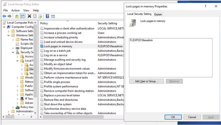
The SQL Server can consume all the memory allocated to the virtual machine. Setting the maximum server memory allows you to reserve sufficient memory for the operating system and other processes running on the virtual machine. Ideally, you should monitor the overall memory consumption of SQL Server during regular business hours and determine the memory requirements. To start, allow SQL Server to consume about 80 percent of the total memory, or leave at least 2 to 4 GB of memory for the operating system. The Maximum Server Memory setting can be dynamically adjusted based on your memory requirements.
Number of Data LUNs and Database Files
For databases that have intensive Data Manipulation Language (DML) operations, you should create multiple data files of the same size to reduce allocation contention. If you have demanding I/O workload deployments, use more than one LUN for the database data files, to help provide optimal distribution of I/O across the storage controllers. For optimal database implementations on a SAN, NetApp recommends the technical report linked here, which discusses the best practices on modern SANs.
SnapCenter Configuration for SQL Database Backup, Restore, Cloning, and Protection
SnapCenter configuration to prepare for SQL Databases protection, includes adding ONTAP storage cluster or SVM, adding hosts, configuring hosts, provisioning storage to hosts for SQL data and logs, provisioning storage to hosts for SnapCenter logs, creating SQL database resource group(s), and creating backup schedule policy.
Procedure 1. Add ONTAP Storage to SnapCenter
Step 1. Launch SnapCenter Web UI, and login using user account with administrator privilege to SnapCenter.
Step 2. In the left navigation pane, click Storage Systems view and click New.
Step 3. Provide the storage system name or IP address. Enter the credentials of the storage user that has the required privileges to access the storage system. Select the appropriate checkbox for Event Management System (EMS) & AutoSupport Settings. This is where you are adding SQL-SVM.
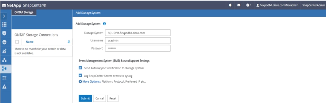
Step 4. Click More Options if you want to modify the default values assigned to platform, protocol, port, and timeout. Click Save.
Step 5. Click Submit.
After ONTAP storage is added, it will display under ONTAP Storage Connections in Storage Systems View.
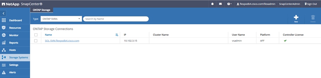
Procedure 2. Add Hosts (Windows VMs) to SnapCenter
When Hosts are added to SnapCenter, SnapCenter Plug-in for SQL Server and SnapCenter Plug-in for Windows are installed on the host.
Step 1. Click the Hosts view and click New.
Step 2. Select Host Type Windows, enter the Host Name or IP address and select one of the credentials of administrator user. Select Microsoft Windows and Microsoft SQL Server plug-ins. Optionally, select the port, and/or install path for the plug-in on the host. Click Submit.
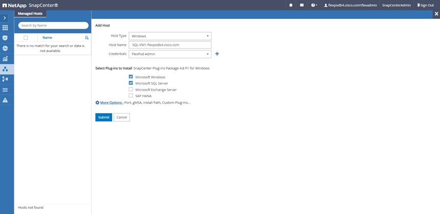
Step 3. Repeat steps 1-3 to add more hosts if required. After hosts are added, these will display in the list of Managed Hosts as shown below. Newly added hosts will require you to configure the directory for SnapCenter logs for that host.
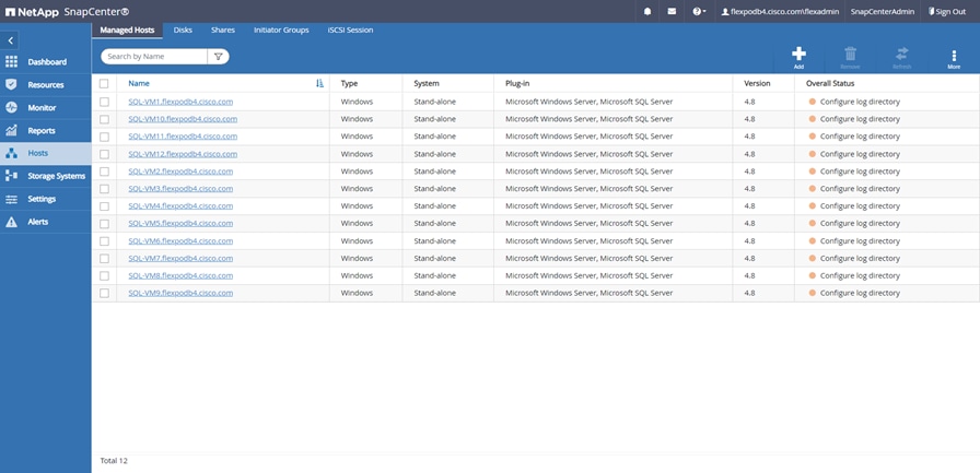
Note: It is recommended to have a directory for SnapCenter logs on NetApp storage. Prior to configuring the directory for SnapCenter logs, you should provision the storage (LUNs) to the Windows host.
Procedure 3. Provision Storage to Windows VMs using SnapCenter
Note: SnapCenter can only provision storage LUNs (disk) to Windows VMs that are added to SnapCenter.
Step 1. From the SnapCenter Hosts view, click the Disks tab. From the Host drop-down list, select the host you want to provision the storage. Click New to start disk creation wizard.
Step 2. Select storage SVM from the Storage System drop-down list. Browse to select the LUN path (FlexVol on SVM). Enter the LUN name. Select the cluster (block) size for Windows File System format, and the label for the Windows File System. Click Next.
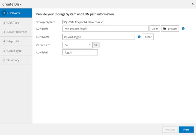
Step 3. For the disk type, select Dedicated, Shared disk, or Cluster Shared Volume (CSV) depending on the solution requirement. In this solution, we are using Dedicated disk. Click Next.
Step 4. Assign drive letter or mount point for the Windows file system mount. Enter drive size and select partition type. Click Next.
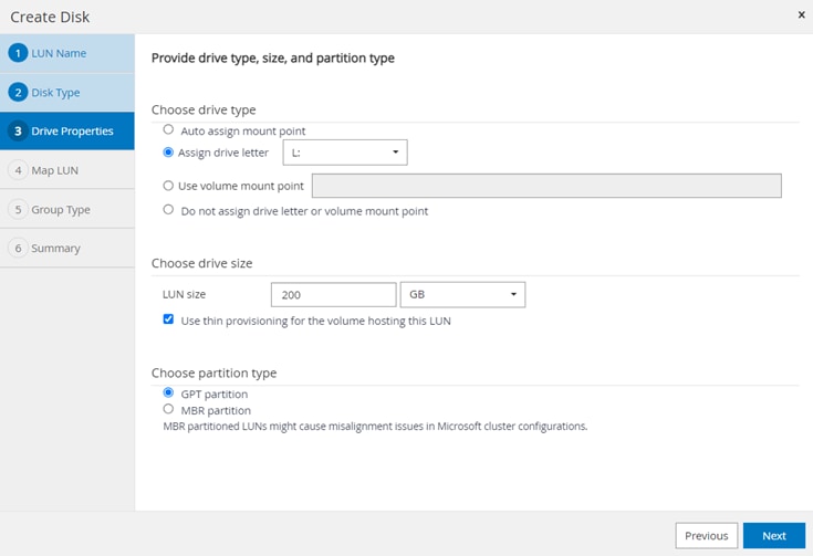
Step 5. Select the initiator to map the LUN (disk). The Initiator already configured on the Windows host is displayed. The iSCSI IQN is available to select after the Software iSCSI initiator is configured on the host. Click Next.
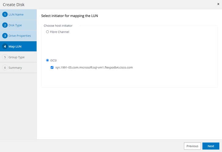
Step 6. When the first LUN (disk) is being provisioned to the Windows Host, select Create new iGroup for selected initiators. Click Next.
Note: For subsequent disk provisioning to the same host, type the first few letters of the known iGroup for the host and names of all existing iGroups beginning with the entered pattern will display in the drop-down list. The names of the iGroups created by SnapCenter follows the pattern SdwIgroup<VmName>.
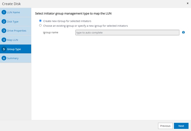
Step 7. Review the Summary and click Finish to complete the disk creation task.
Step 8. SnapCenter will create a LUN on SVM on the NetApp Storage. Rescan the disks on the Windows Host, create partition, format file system, and mount at provided Drive letter or Mount Point.
Procedure 4. Configure Log Directory for Windows Virtual Machines
Step 1. Click any of the host names and it will display the Host Details. Click Configure log directory.
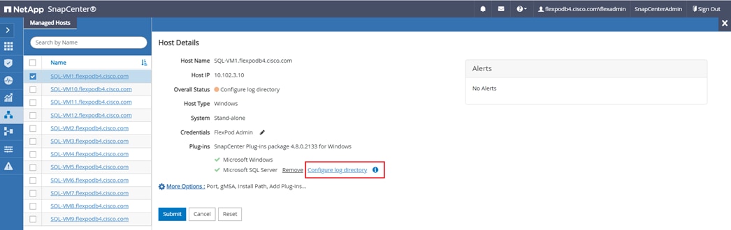
Step 2. Browse to select the SnapCenter Log directory. The log directory should have been created on the drive. Click Save.
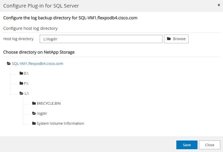
Procedure 5. Create New SQL Server Backup Policy
Step 1. In the left navigation pane, select Settings. In the Settings page, select Policies. Click New. In the Name page, enter the policy name and description. Click Next.
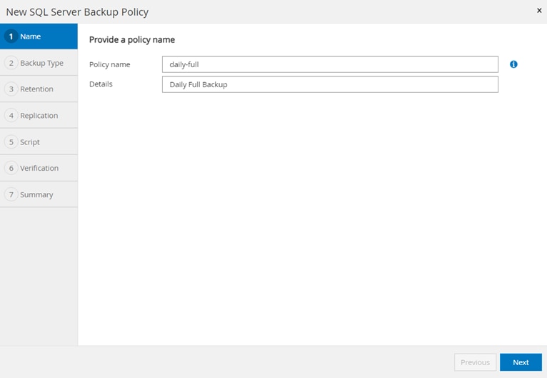
Step 2. Select Backup type and the frequency of the backup. Click Next.
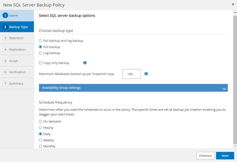
Step 3. Select the retention settings for up-to-the-minute restore operation. Click Next.
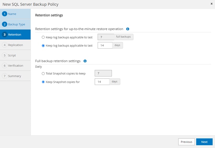
Step 4. Select secondary replication options, policy label, and enter a number for the retry count for replication attempts. Click Next.
Step 5. Enter the details of the scripts you want to run before and after backup. Click Next.
Step 6. Enter the verification schedule details. Click Next.
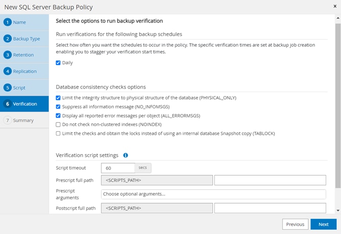
Step 7. Review the Summary of the tasks and click Finish. Backup policy is now created as shown below.
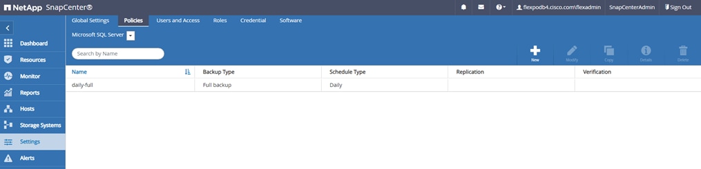
Procedure 6. Create Resource Groups
Resource groups are groups of SQL databases and corresponding logs that are backed up together. A backup policy is associated with the resource group to back up the SQL databases and retain a certain number of backups as defined in the policy.
Step 1. Select Resources view and from the drop-down list select Database. All databases of SQL server instances running on all added hosts will be displayed. Other resource types are SQL Server “Instance”, SQL Server “Availability Group” (AG) and SnapCenter “Resource Group”.
Step 2. Decide which user databases need to be backed up in a group, so they can be added into a single resource group.
Step 3. Select Resource Group from the View drop-down list. Click New Resource Group.
Step 4. Enter the name of the new resource group, any tag for the group and custom name format, if required. The custom name format can contain the resource group name, policy name, schedule name, and any custom text entered in the dialog shown below. Click Next.
Step 5. Select specific or all hosts, resource type databases, and SQL server instance name from the drop-down list. From the list of databases, select the user databases to add into resource group.
Step 6. Select more databases from the different SQL Server instances if needed, to add those into the same resource group to backup simultaneously according to same policy and schedule. Click Next.
Step 7. Select one or more policies from the drop-down list of available policies or create new policies by clicking ‘+’. Here, we will select the policy that we created in the previous section. Click Next.

Step 8. Click + under Configure Schedules. Enter a start date, time, and Expires on if it’s required to end the backup schedule on a specific day and time. Click OK.
Step 9. Click Next.
Step 10. Select a Verification server from the drop-down list.
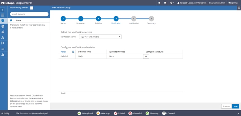
Step 11. In Add Verification Schedules; select either Run verification after backup or Run scheduled verification and select a time from the drop-down list. Click OK.
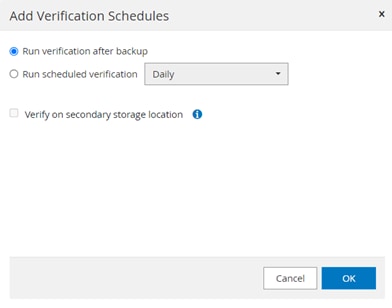
Step 12. Click Next.
Step 13. To configure Notification, enter the email details and select if the job report should be attached to notification emails. Click Next.
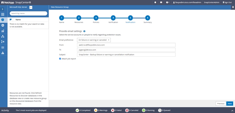
Step 14. Review the Summary and click Finish.
Resource group gets created as shown below.
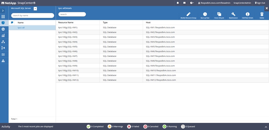
Step 15. Repeat steps 3-14 if you require additional resource groups.
Note: For more information on protecting Microsoft SQL Server Databases using SnapCenter, go to:
https://docs.netapp.com/us-en/snapcenter-48/protect-scsql/concept_how_resources_resource_groups_and_policies_are_used_for_protecting_sql_server.html
System Validation and Testing
This chapter contains the following:
● Performance Tests and Results
● Database Performance Comparison between Cisco UCS B200 M5 and Cisco UCS X210c M7
● SnapCenter Validation for SQL Databases
● Disaster Recovery of Microsoft SQL Server Databases with NetApp CVO
This section provides a high-level summary of the performance testing and validation results for the FlexPod solution. The following tests were performed on the solution:
● Demonstrate the maximum IO Capacity of the NetApp AFF A400 storage array (single pair of Controllers) using the DiskSpd tool for 70R:30W and 10R:90W read: write percent workloads.
● Demonstrate OLTP database performance scalability for both scale-up and scale-out scenarios using single node ESXi and a four node ESXi cluster created using Cisco UCS X210c M7 compute nodes with a sample 100-GB test database using the HammerDB tool.
Note: This FlexPod configuration was successfully verified by performing multiple failure tests to determine database persistence and performance.
● Network link failures tests between Cisco UCS fabric interconnects and Cisco UCS 9508 Series blade chassis and fabric interconnects and upstream Cisco Nexus switches were performed to validate the storage connectivity from the Cisco UCS X210c M7compute node and NetApp A400 storage array.
Validated Test Configuration for SQL Server Workload
Table 8 lists the hardware and software versions used during the solution validation process.
Note: Cisco and NetApp have interoperability matrixes that should be referenced to determine support for any specific implementation of FlexPod.
Table 8. Test Configuration used
| Layer |
Devices |
Image |
| Computing |
Cisco UCS 6536 Fabric Interconnect One Cisco UCS 9508 blade chassis with two UCS 9108 IFMs Four Cisco UCS X210c M7 blades |
4.2(3d)
5.1(1.230052) |
| CPUs (On each compute node) |
2x Intel Xeon 4th generation Scalable 6448H Processor, Each CPU is with 32 Cores running 2.4GHz |
|
| Memory (On each compute node) |
16x 32GB DIMMs operating at 4800 MT/s |
|
| Network |
2x Cisco Nexus 93360YC-FX2 switches |
NXOS:10.2(5) |
| Storage |
2x NetApp A400 Storage controllers (one HA Pair) with 24x 1.8TB NVMe SSDs |
NetApp ONTAP 9.12.1P4 |
| Hypervisor |
VMware vSphere 8.0 Cisco UCS VIC 15231 nenic drivers |
8.0 |
| Guest OS |
Microsoft Windows Server 2022 (Standard Edition) |
|
| Database |
Microsoft SQL Server 2022 (Enterprise Edition) |
|
| Testing tool |
HammerDB (SQL Server workload simulator) and DiskSpd (synthetic IO workload generator) |
|
| Performance Monitoring Tool |
NetApp AIQUM, ESXi esxtop, Windows PerfMon |
|
Maximum IO Capacity of A400 Storage Controllers (HA Pair)
This FlexPod solution was tested with a synthetic I/O testing tool (DiskSpd tool from Microsoft), to ensure that the system is deployed optimally and configured following all the FlexPod best practices. For this test, 12 virtual machines were deployed (3 virtual machines per node) across a 4-node ESXi cluster. Each virtual machine was configured with two iSCSi disks from the NetApp A400 storage array using the in-guest Microsoft iSCSI initiator. The DiskSpd tool was installed on each virtual machine and configured to run the I/O test on two disks with various read: write ratios with an 8-KB block size.
The following script, which generates IO on two iSCSI NetApp volumes (E:\ and F:\) with 70:30 and 10:90 read: write ratio, was run on all 12 virtual machines concurrently distributed across 4-node ESXi cluster.
.\diskspd -t8 -o2 -b8k -r -w30 -d1800 -Sh -L -c15G E:\testfile.dat F:\testfile.dat
.\diskspd -t8 -o2 -b8k -r -w90 -d1800 -Sh -L -c15G E:\testfile.dat F:\testfile.dat
The following figures (captured using the NetApp AIQUM tool) shows the IOPS, and throughput driven by all the twelve virtual machines. They were able to drive nearly 277,000 I/O operations with a 70:30 percent read-write ratio at around 1millisecond latency and nearly 187,000 IO operations with 10:90 percent read-write ratio at 1.5ms latency.
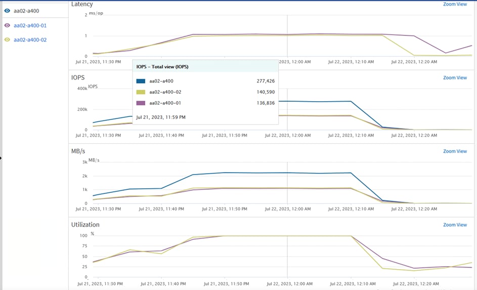
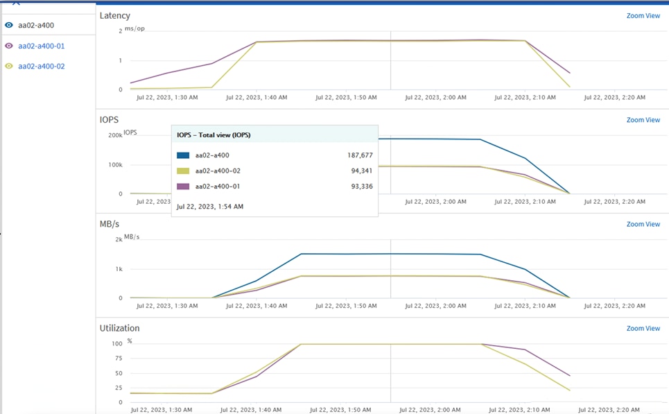
The storage system utilization was close to 100 percent, indicating that the storage system was at or near its maximum performance capability. However, the best practice is to operate the storage system below 80 percent utilization during normal operations to prevent significant performance impacts during a controller failure scenario. For additional I/O performance requirements, another pair of NetApp storage controllers can be added to the existing cluster or upgrade to the high-end storage controllers.
SQL Server Database Performance Scalability Tests
The objective of these tests is to demonstrate how performance scales as more SQL virtual machines are added with in a single ESXi host (one Cisco UCS X210c M7) and a 4-node ESXi cluster (four Cisco UCS X210c M7s). Table 9 lists the virtual machine configuration and database schema details used for these tests.
Table 9. SQL Server Virtual Machine Configuration
| Component |
Details |
| Virtual Machine Configuration |
8 vCPUs, 12GB memory (9G is allocated to SQL Server) |
| Storage Volumes |
1x 250G volume for tempdb and test database data files 1x 200G volume for tempdb and test database transaction log files |
| Database |
Microsoft SQL Server 2022 (Enterprise edition) |
| Guest OS |
Windows Server 2022 |
| Workload generation per VM |
Database Size: 100G
●
Targeted Total IOPS per VM: ~10,000
●
Performance Metrics Collected:
●
Transactions Per Second (TPM/60) from HammerDB
●
IOPS from Windows PerfMon
●
ESXi esxtop metrics
●
NetApp AIQUM for storage level IO metrics
|
Database Performance Scalability with in Single X210c ESXi Host
This test focuses on how a single Cisco UCS X210c M7 ESXi host can respond as more SQL Server workload virtual machines are loaded on the same host. As shown below, a single SQL Server virtual machine delivered about 9100 Transactions Per Second (TPS) driving about 10,000 IOPS and utilizing 9% CPU on the ESXi host. As more SQL Server virtual machines were added to the same host (scaled to up to six virtual machines), the TPS, IOPS and ESXi host CPU usage scaled nearly linearly because no bottlenecks were discovered within the FlexPod System.
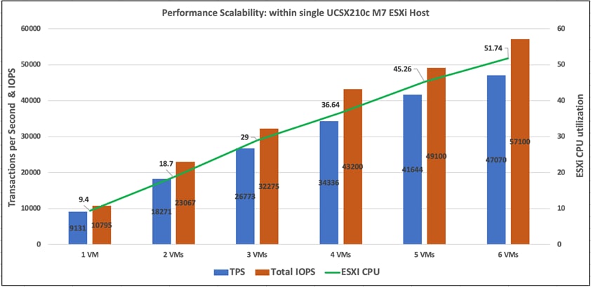
Note: The IO latencies were maintained under one milli second during the above tests.
Database Performance Scalability Across ESXi Cluster
The objective of this test is to demonstrate the database performance scalability when multiple SQL Server virtual machines are deployed across a four-node ESXi cluster.
This test started with 4 virtual machines spread across the cluster and then was scaled by groups of 4 virtual machines up to 12 virtual machines (3 virtual machines per ESXi host).
As shown below, 4 virtual machines (1 virtual machine per node) collectively delivered about 33,000 Transactions Per Second, driving about 40,000 IOPS and utilizing 9% CPU on each ESXi host in the cluster. As more virtual machines were added across the ESXi cluster, TPS, IOPS and the CPU utilization of the cluster also scaled nearly linearly because no bottlenecks were discovered within the FlexPod System.
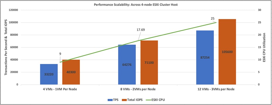
Note: The IO latencies were maintained under one millisecond during these tests.
Database Performance Comparison between Cisco UCS B200 M5 and Cisco UCS X210c M7
The objective of this performance comparison study is to understand the benefits of migrating SQL Server database workloads from older generation compute platform Cisco UCS B200 M5 power by Intel 2nd generation processors to the latest compute platform Cisco UCS X210c M7 powered by Intel 4th generation processors.
For this study, the compute nodes Cisco UCS B200 M5 (installed in Cisco UCS 5108 chassis) and Cisco UCS X210c M7 (installed in Cisco UCS 9508 chassis) are connected to the same NetApp A400 storage array through a pair of Fabric Interconnect 6536 and Cisco Next 93360YC-FX2 switches over 100Gbps network. Table 10 lists the test configuration of the two compute platforms used for this validation.
Table 10. Cisco UCS B200 M5 and X210c M7 Configuration
| Details |
Cisco UCS B200 M5 |
Cisco UCS X210c M7 |
| CPUs |
2x Intel 2nd generation 6248 CPUs, each with 20 cores running at base frequency of 2.5GHz |
2x Intel 4th generation 6448H CPUs, each with 32 cores running at base frequency of 2.4GHz |
| Total Cores used |
40 |
64 |
| Total Memory |
16x 32G DIMMs, 512G running at 2933 MT/S |
16x 32G DIMMs, 512G running at 4800 MT/S |
| Virtual Machine Configuration |
8 vCPUs, 12G Memory |
|
| Guest OS |
Windows Server 2022 |
|
| Relational DB engine and DB Size |
SQL Server 2022, DB Size: 100G |
|
| Hypervisor |
VMware vSphere ESXi 8.0 |
|
| Storage and Volumes |
NetApp A400, 1x 250G for data files 1x 200G for Transaction log files |
|
| Testing tool |
HammerDB, 12 users used to simulate Operational Transactions |
|
Note: As shown in Table 10, except the compute platform, the remaining components are kept identical for this test.
Performance Comparison
Four SQL Server virtual machines are created and stressed with same HammerDB user load on each compute platform. The performance metrics observed from each platform are listed in Table 11.
Table 11. Performance Metrics for Cisco UCS B200 M5 and Cisco UCS X210c M7 compute nodes
| Details |
Cisco UCS B200 M5 (from 4 VMs) |
Cisco UCS X210c M7 (from 4 VMs) |
| Total TPS |
30204 |
34869 |
| Total ESXi host CPU utilization |
66 |
36 |
| Total IOPS |
36200 |
43300 |
| TPS improvement over Cisco UCS B200 M5 |
|
15% |
From these test results, four SQL Server virtual machines tested on Cisco UCS B200 M5 delivered 30204 TPS by utilizing nearly 66% CPU on the ESXi host. While the same workload on Cisco UCS X210c M7 delivered 34869 TPS (which is nearly 15% better compared to Cisco UCS B200 M5) consuming 36% CPU on the ESXi host. There are significant CPU resources still available to accommodate additional workloads on Cisco UCS X210c M7. Further testing was done by adding four more virtual machines (total of eight VMs) on Cisco UCS X210c M7 compute node and executed the same workload again with eight HammerDB clients.
Table 12 lists eight VMs test results.
Table 12. Performance Metrics for Cisco UCS B200 M5 and Cisco UCS X210c M7 compute nodes
| Details |
Cisco UCS B200 M5 (from 4 VMs) |
Cisco UCS X210c M7 (from 4 VMs) |
Cisco UCS X210c M7 (from 8 VMs) |
| Total TPS |
30204 |
34869 |
61965 |
| Total ESXi host CPU utilization |
66 |
36 |
68 |
| Total IOPS |
36200 |
43300 |
68500 |
| TPS improvement over Cisco UCS B200 M5 |
15% |
2 times |
|
Eight SQL Server virtual machines on Cisco UCS X210c M7 delivered 61965 TPS, which is nearly 2 times more TPS (with 2 times more VMs) by utilizing nearly same CPU (68%) as that of Cisco UCS B200 M5 test.
This proves the latest generation compute platform (Cisco UCS X210c M7) can accommodate twice the workload compared to older compute platform (Cisco UCS B200 M5).
Price Comparison
This section focuses on the price benefits that you can achieve by migrating SQL Server workloads from Cisco UCS B200 M5 to the Cisco UCS X210c M7 platform. The latest BoMs (Bill of Materials) or the estimate for both the platforms are created using Cisco Commerce Workspace (CCW) tool. The other components such as FIs, Switches, Storage and so on, are not included in the estimate as they are same for both the platforms. Table 13 lists the key component price details of both the platforms. Refer to Appendix A - Bill of Materials for the complete CCW BoM estimates.
| Details |
Cisco UCS B200 M5 |
Cisco UCS X210c M7 |
| Cost of two CPUs |
24717 |
20536 |
| Cost of 16x 32G DIMMs |
50561 |
36528 |
| Base price |
4223 |
6344 |
| Intersight Essential License cost for 3 Years |
1260 |
1260 |
| VIC Cost |
1646 |
1740 |
| 24x7x4OS Support |
948 |
1761 |
| Total Cost of Ownership (TCO) |
83355 |
68169 |
| % Price Difference compared to B200 M5 |
22% |
|
As shown in Table 13, the TCO of Cisco UCS X210c M7 compute node is 22 percent less expensive compared to Cisco UCS B200 M5 compute node.
From these two comparisons (Performance and Price), it is evident that the latest compute platform has below advantages compared to older compute platform.
● Consolidate nearly two times more SQL Server database workloads without performance impact on Cisco UCS X210c M7 compute nodes there by reducing datacenter footprint by 2 times as well as associated power savings (Opex cost savings).
● This consolidation allows reduction in the overall licensing requirements of various software components such as ESXi Hypervisor, SQL Server, Intersight and so on.
● This consolidation also brings cost reduction of 22 percent using Cisco UCS X210c M7.
This proves workload migration from older platform to the newer platforms will not only accommodate 2 times more workloads but also at a cheaper cost.
SnapCenter Validation for SQL Databases
This section details the SnapCenter validation for Microsoft SQL Server Databases and showcases the following use-cases:
● On-Demand Backup of SQL databases
● SQL database Restore from Backup
● SQL database Cloning from Backup
Verify On-Demand Backup of SQL Databases
Note: The resource group of SQL databases should have an on-demand backup for the resource group.
Procedure 1. Trigger an On-Demand Backup
Step 1. Launch SnapCenter Web UI. Select Resources view. Click a Resource group.
Step 2. Click Backup Now.
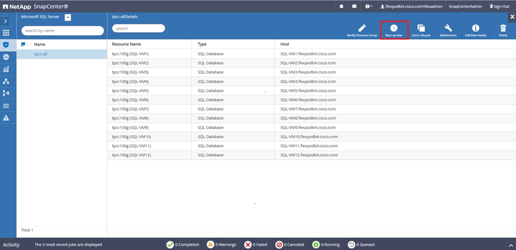
Step 3. Select a policy to use for the on-demand backup. Select Verify after backup and then click Backup.
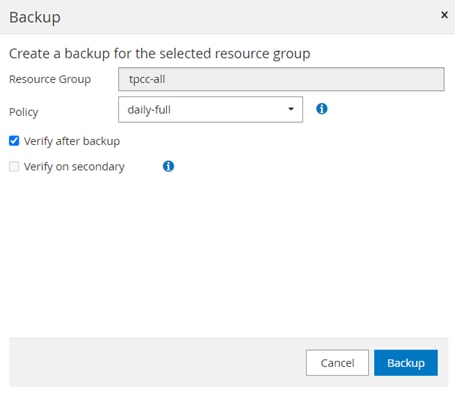
Step 4. Go to the Monitor tab, click Jobs, and verify the status of the triggered backup job as shown below.
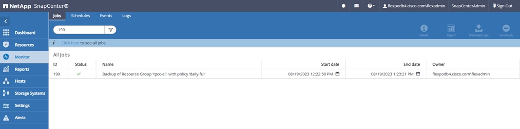
Use NetApp Storage Snapshots for Data Protection and Quick Recovery of SQL Databases
NetApp SnapCenter creates application-consistent snapshot copies and completes data protection operations, including snapshot copy-based backup, clone, restore, and backup verification operations.
When you start the backup process for a given user database, a copy-based backup in the form of a snapshot is created on the same volume on which the user database resides, as shown below. This snapshot copy can be used for data-protection operations such as the recovery and cloning of databases.
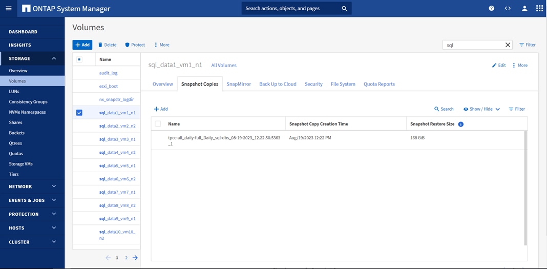
Verify SQL Database Restore from Backup
The section describes the steps to restore the SQL database from backup using NetApp SnapCenter.
Note: Before proceeding, ensure that the backup of the SQL databases Resource group has already been created using SnapCenter.
Procedure 1. Restore Database from Backup
Step 1. Launch SnapCenter Web UI. Select Resources view. Click Resource View and then click a resource group name.
Step 2. Click the name of a database resource to restore from a backup.
Step 3. The list of backups for the selected resource is displayed. Click the name of the backup from which to restore the database.
Step 4. Click Restore.
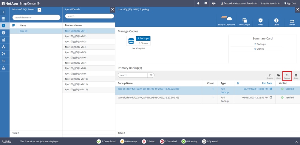
Step 5. Select the host where the database is restored. Click Next.
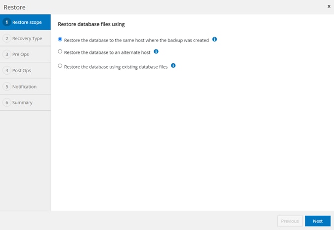
Step 6. Select the desired recovery of logs from backup. Click Next.
Step 7. Select the pre restore options for the database and the optional script to run before restoring from the backup. Click Next.
Step 8. Select the post restore options for the database and the optional script to run after restoring from the backup. Click Next.
Step 9. Enter notification email details for the restore job. Click Next.
Step 10. Review the Summary of restore task and click Finish.
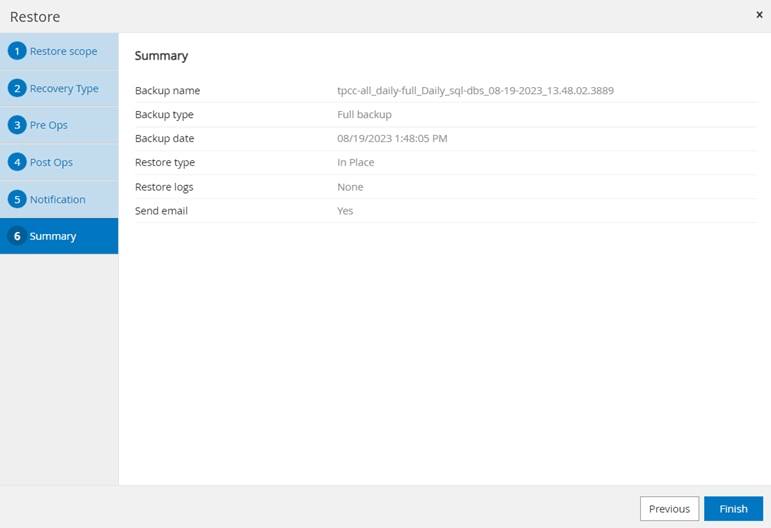
Step 11. Go to the Monitor tab, click Jobs, and enter restore in filter to see job status of restore operation. See details or download the log if needed.
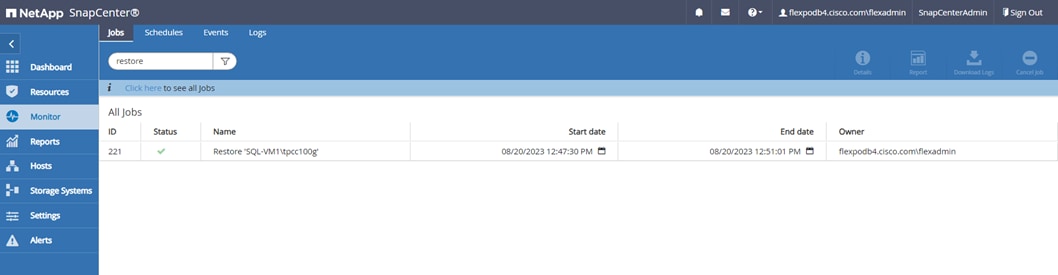
Verify SQL Database Cloning from Backup
This section describes the steps for cloning SQL database from backup using NetApp SnapCenter.
Note: Before proceeding, ensure that the backup of SQL databases Resource group has been created using SnapCenter.
Procedure 1. Create a Clone of a Database from the Backup
Step 1. Launch SnapCenter Web UI. Select Resources view. Click a resource view and then click a resource group name.
Step 2. Click the name of a database resource to clone from a backup.
Step 3. The list of backups for the selected database is displayed. Select the backup to clone the database from and click Clone.
Step 4. Enter clone server, SQL instance, and clone name. Select the option for Windows mountpoint to mount database. Click Next.
Step 5. Select log options. Click Next.
Step 6. Specify the optional pre and post scripts to run before and after clone operation. Click Next.
Step 7. Enter the notification email settings for the clone operation notifications. Click Next.
Step 8. Review the Summary of the clone operation to be triggered. Click Finish.
Step 9. Go to Monitor view, click Jobs, and monitor the status of the clone job.
Disaster Recovery of Microsoft SQL Server Databases with NetApp CVO
Data protection and disaster recovery are important goals for businesses continuity. Disaster recovery (DR) allows organizations to failover the business operations to a secondary location and later recover and failback to the primary site efficiently and reliably. Disaster recovery requires all the workloads running on the primary site be reproduced fully on the DR site. It also requires having an up-to-date copy of all enterprise data, including databases, file services, NFS and iSCSI storage, and so on.
NetApp Cloud Volumes ONTAP delivers a solution for enterprise data management where data can be efficiently replicated from FlexPod Datacenter to Cloud Volumes ONTAP deployed on a public cloud like Azure. By leveraging cost-effective and secure public cloud resources, Cloud Volumes ONTAP enhances cloud-based DR with highly efficient data replication, built-in storage efficiencies, and simple DR testing, managed with unified control, drag-and-drop simplicity, providing cost-effective, bullet-proof protection against any kind of error, failure, or disaster. Cloud Volumes ONTAP provides SnapMirror as a solution for block-level data replication that keeps the destination up to date through incremental updates.
The following figure represents the solution topology composed of the FlexPod Datacenter on-premises environment, NetApp Cloud Volumes ONTAP (CVO) running on Microsoft Azure, and the NetApp BlueXP SaaS platform.
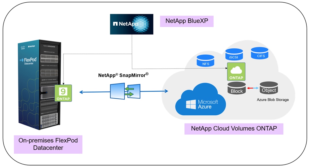
The data plane runs between the ONTAP instance running on all-flash FAS in FlexPod and the NetApp CVO instance in Azure by leveraging a secure site-to-site VPN connection. The replication of SQL workload data from the on-premises FlexPod Datacenter to NetApp Cloud Volumes ONTAP is handled by NetApp SnapMirror replication. An optional backup and tiering of the cold data residing in the NetApp CVO instance to Azure Blob Storage is also supported with this solution.
The following sections describe the configuration steps required to validate the DR of SQL Server databases using NetApp CVO.
Deploy Connector in Azure from BlueXP
To create a Connector in Azure from BlueXP, you need to set up your networking, prepare Azure permissions, and then create the Connector. Creating the Connector from BlueXP deploys a virtual machine in Azure using a default configuration.
For detailed information about the prerequisites for deploying connector in Azure, go to: https://docs.netapp.com/us-en/bluexp-setup-admin/task-install-connector-azure-bluexp.html.
Note: To access the NetApp BlueXP and other cloud services, you need to sign up on NetApp BlueXP. For setting up workspaces and users in the BlueXP account, click here. You need an account that has permission to deploy the Connector in your cloud provider directly from BlueXP. You can download the BlueXP permissions from here.
Procedure 1. Deploy a Connector in Azure from BlueXP
Step 1. From the Connector drop-down list and select Add Connector.
Step 2. Select Microsoft Azure as your cloud provider. Click Continue.
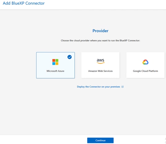
Step 3. From the Deploying a BlueXP Connector page, under Authentication, select the authentication option that matches how you set up Azure permissions:
● Select Azure user account to log in to your Microsoft account, which should have the required permissions.
● Select Active Directory service principal to enter information about the Azure Active Directory service principal that grants the required permissions:
◦ Application (client) ID
◦ Directory (tenant) ID
◦ Client Secret
Step 4. Follow the steps in the wizard to create the Connector:
● VM Authentication: Select an Azure subscription, a location, a new resource group or an existing resource group, and then select an authentication method for the Connector virtual machine that you’re creating.
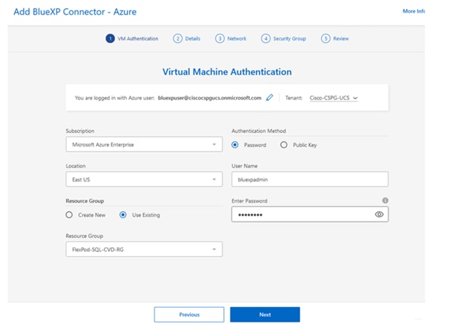
● Details: Enter a name for the instance, specify tags, and choose whether you want BlueXP to create a new role that has the required permissions, or if you want to select an existing role that you set up with the required permissions.
● Network: Select a VNet and subnet, whether to enable a public IP address, and optionally specify a proxy configuration.
● Security Group: Select whether to create a new security group or whether to select an existing security group that allows the required inbound and outbound rules.
● Review: Review your selections to verify that your set up is correct.
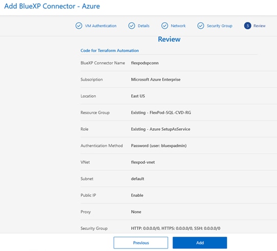
Step 5. Click Add. The virtual machine should be ready in about 7 minutes. After the process is complete, the Connector is available for use from BlueXP, as shown below.
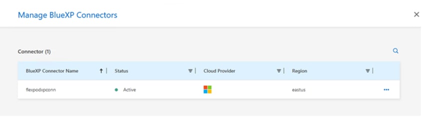
Deploy Cloud Volumes ONTAP in Azure
You can launch a single node system or an HA pair in Azure by creating a Cloud Volumes ONTAP working environment in BlueXP. You need the following to create a working environment.
● A Connector that’s up and running. You should have a Connector that is associated with your workspace.
● An understanding of the configuration that you want to use. You should have chosen a configuration and obtained Azure networking information. For details, see Planning your Cloud Volumes ONTAP configuration.
● An understanding of what’s required to set up licensing for Cloud Volumes ONTAP. Learn how to set up licensing.
Note: In this solution, a single-node Cloud Volumes ONTAP system in Azure was deployed.
Procedure 1. Deploy CVO Instance in Azure using BlueXP
Step 1. From the left navigation menu, select Storage > Canvas.
Step 2. On the Canvas page, click Add Working Environment and follow the prompts.
Step 3. Select a Location: Select Microsoft Azure and Cloud Volumes ONTAP. Click Add new.
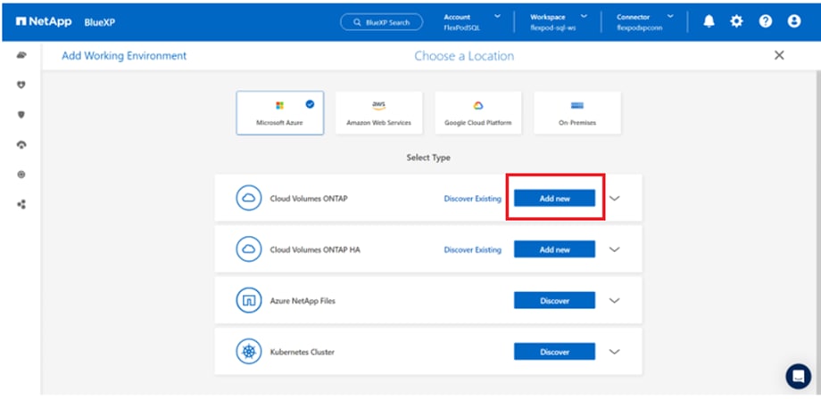
Step 4. Details and Credentials: Optionally, change the Azure credentials and subscription, specify a cluster name, add tags if needed, and then specify credentials.
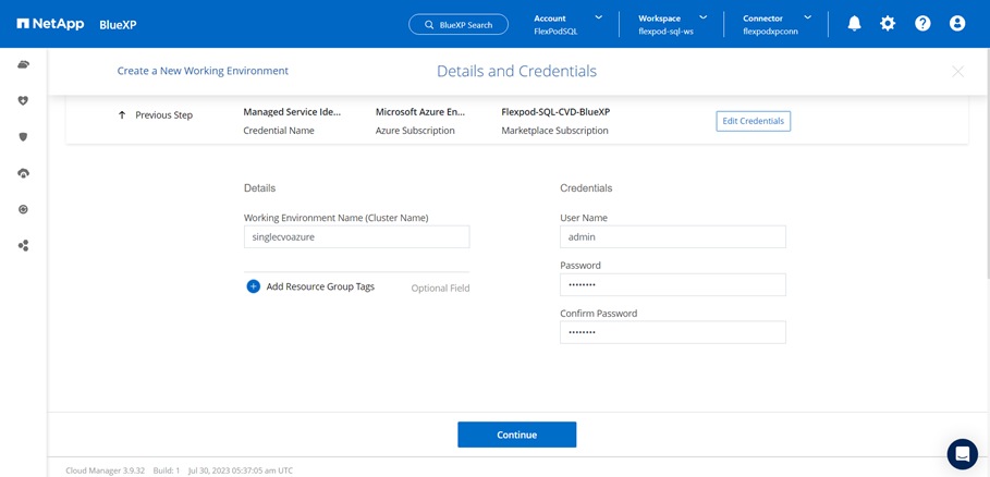
Step 5. Services: Keep the services enabled or disable the individual services that you don’t want to use with Cloud Volumes ONTAP.
Step 6. Location: Select a region, availability zone, VNet, and subnet, and then select the checkbox to confirm network connectivity between the Connector and the target location.
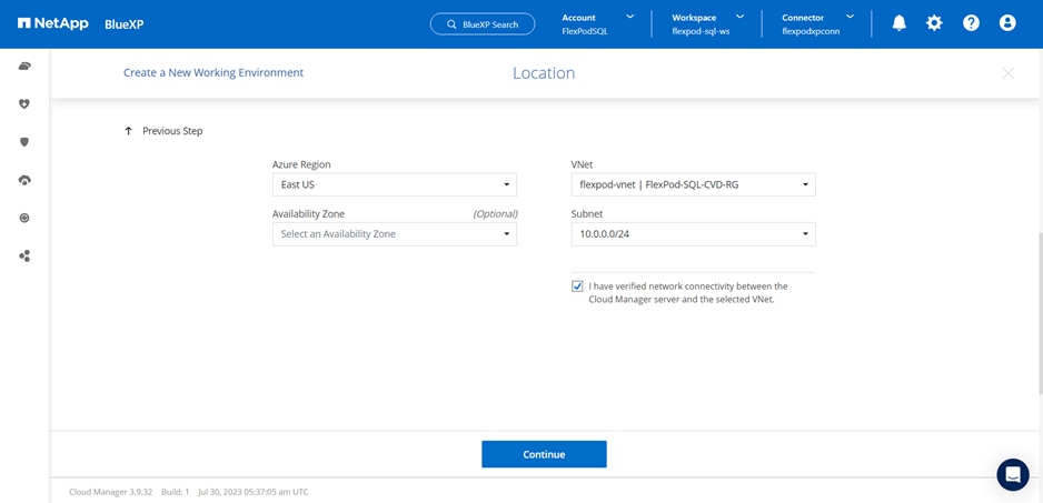
Step 7. Connectivity: Select a new or existing resource group and then choose whether to use the predefined security group or to use your own.
Step 8. Charging Methods and NSS Account: Specify which charging option you would like to use with this system, and then specify a NetApp Support Site account. Learn about licensing options for Cloud Volumes ONTAP. In this solution, CVO Freemium offering was selected for testing purposes.
Step 9. Preconfigured Packages: Select one of the packages to quickly deploy a Cloud Volumes ONTAP system or click Change Configuration to select your own configuration. In this solution, for testing purpose, “POC and small workloads” were selected. You can select any of the packages based on the requirements or create your own configurations.
Note: If you choose one of the packages, you only need to specify a volume and then review and approve the configuration.
Step 10. Create Volume: Enter details for the new volume or click Skip. This step was skipped for this solution.
Step 11. Review & Approve: Review and confirm your selections.
● Review details about the configuration.
● Click More information to review details about support and the Azure resources that BlueXP will purchase.
Step 12. Select the I understand… check boxes. Click Go.
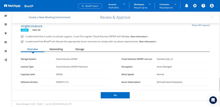
The single node CVO deployment is initiated. You can track the progress in the timeline.
Note: The single node CVO deployment could take about 25 minutes.
BlueXP deploys the Cloud Volumes ONTAP system as shown below:
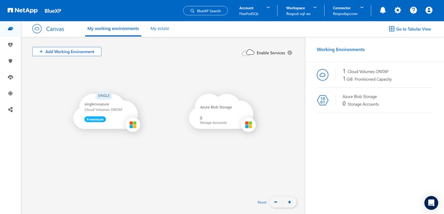
Procedure 2. Add on-premises FlexPod storage to BlueXP
Note: Make sure to configure VPN between Azure and on-prem FlexPod Datacenter, so that all Services of on-prem ONTAP show up in BlueXP. Complete the following steps to add your FlexPod storage to the working environment using NetApp BlueXP.
Step 1. From the navigation menu, select Storage > Canvas.
Step 2. On the Canvas page, click Add Working Environment and select On-Premises.
Step 3. Next to On-Premises ONTAP, select Discover.
Step 4. On the Discover Cluster page, enter the cluster management IP address, and the password for the admin user account. Click Discover.
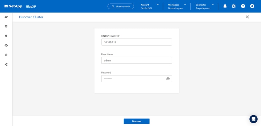
BlueXP discovers the on-prem ONTAP cluster and adds it as a working environment on the Canvas, as shown below.
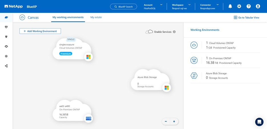
Procedure 3. Configure SnapMirror Replication between on-premises FlexPod DataCenter and Cloud Volumes ONTAP
NetApp SnapMirror replicates data at high speeds over LAN or WAN, so you get high data availability and fast data replication in both virtual and traditional environments. When you replicate data to NetApp storage systems and continually update the secondary data, your data is kept current and remains available whenever you need it. No external replication servers are required.
Step 1. From the navigation menu, select Storage > Canvas.
Step 1. On the Canvas, select the working environment that contains the source volume, drag it to the working environment to which you want to replicate the volume, and then select Replication.
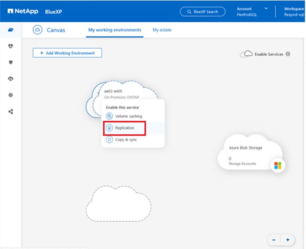
The remaining steps explain how to create a synchronous relationship between CVO and on-prem ONTAP cluster.
Step 2. Source and Destination Peering Setup: If this page appears, select all the intercluster LIFs for the cluster peer relationship. The intercluster network should be configured so that cluster peers have pair-wise full-mesh connectivity, which means that each pair of clusters in a cluster peer relationship has connectivity among all of their intercluster LIFs.
Step 3. Source Volume Selection: Select the volume that you want to replicate. The on-prem SQL data volume “sql_data10_vm10_n1_test” of size 15GB was selected as the source volume.
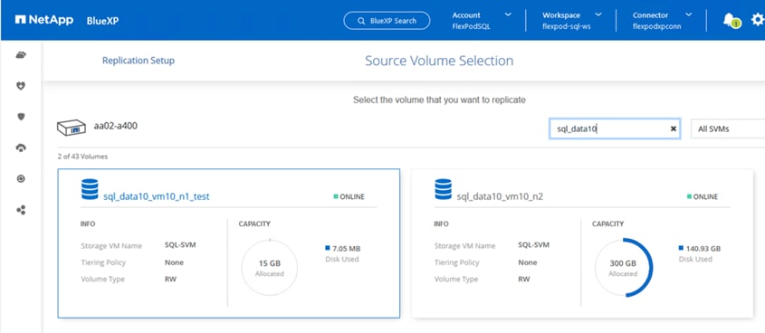
Step 4. Destination Disk Type and Tiering: If the target is a CVO system, select the destination disk type and choose whether you want to enable data tiering.
Step 5. Destination Volume Name: Specify the destination volume name and choose the destination aggregate.
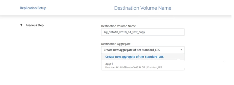
Step 6. Max Transfer Rate: Specify the maximum rate (in megabytes per second) at which data can be transferred.
Step 7. Replication Policy: Choose a default policy or select Additional Policies, and then select one of the advanced policies. For help, learn about replication policies.
Step 8. Schedule: Choose a one-time copy or a recurring schedule. Several default schedules are available.
Step 9. Review: Review your selections and click Go.
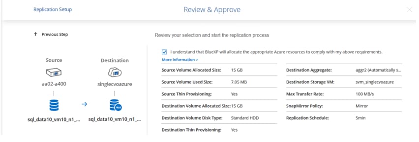
For detailed information about these configuration steps, click here.
BlueXP starts the data replication process. You can see the Replication service that is established between on-premises ONTAP system and Cloud Volumes ONTAP.
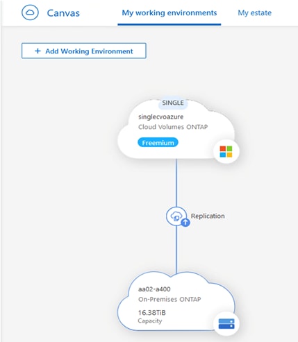
Note: Follow steps 1-9 to setup data replication for the on-prem SQL log volume “sql_log10_vm10_n2_test” of size 10GB.
In the Cloud Volumes ONTAP cluster, you can see the newly created data and log volumes as shown below:
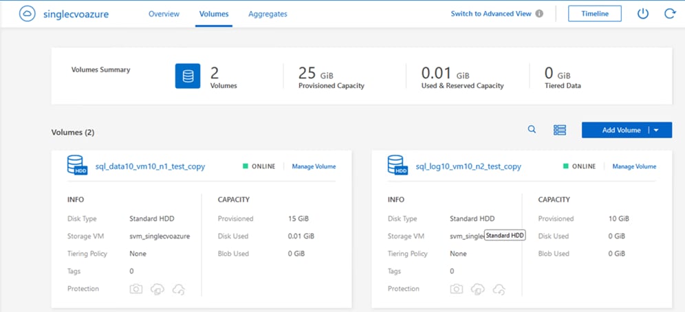
Step 10. You can also verify that the SnapMirror relationship is established between the on-premises volumes (both data and log) and the cloud volumes, as shown below. More information on the replication task can be found under the Replication tab.
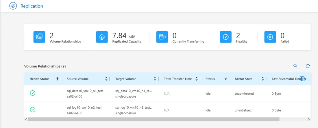
Note: For testing purpose, we had created one data volume (sql_data10_vm10_n1_test) and one log volume (sql_log10_vm10_n2_test) of size 15GB and 10GB respectively on the on-prem ONTAP storage. We have selected those volumes for data replication in the above configuration steps. On-prem data and log LUNs have been created from those data and log volumes, of which data LUN is of size 10GB and log LUN is of size 5GB. These LUNs are mapped to on-prem Windows VM (here SQL-VM10) running Microsoft SQL Server 2022. We have created a sample database of size 1G with one data and one T-log file stored on the corresponding data and log volumes, as shown below.
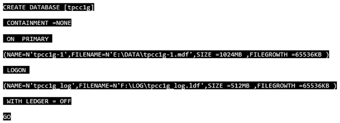
Note: You can either replicate 2 on-prem volumes (one for data and one for log) as previously discussed or go with single volume (create both data and log LUNs from this volume).
Procedure 4. Configure Windows VM in Azure
Step 1. Deploy a Windows Virtual Machine in Azure (as shown below) for testing and validating data transfer from on-prem FlexPod to CVO.
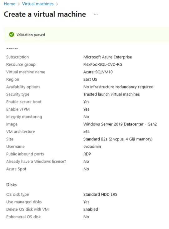
Step 2. Copy SQL binaries from on-prem Windows VM to Azure VM and install Microsoft SQL Server 2022.
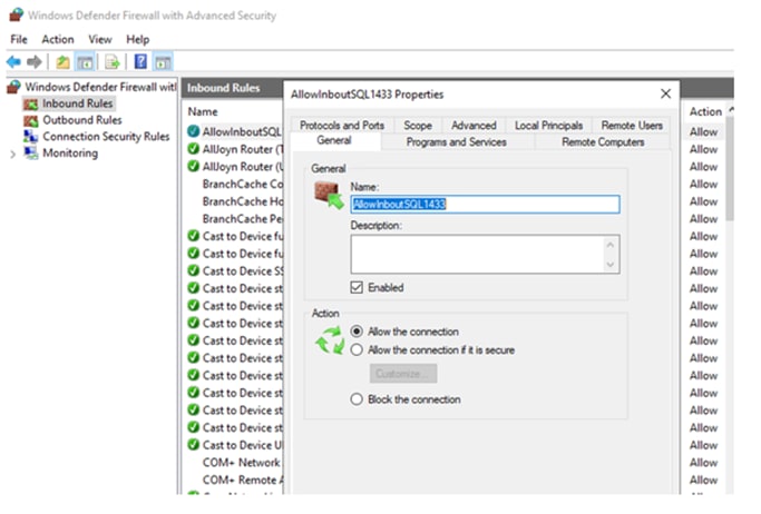
Step 3. Note that the LUNs are created automatically on the CVO end after SnapMirror Replication between on-prem and CVO volumes. Create the igroup for the Azure VM in CVO using its iSCSI initiator IQN name. Map the data and log LUNs in CVO to this igroup. Now, the LUNs can be easily mounted to the Azure VM as shown below.
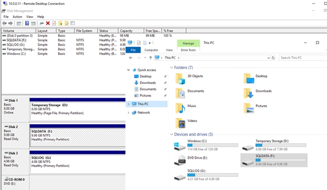
Note: CVO volumes are of type “DP” (data protection), so it is read-only volume. Users cannot write or attach databases to those volumes.
Validating Data Replication
In this section, let’s take a few measures to verify the integrity of the data replication from the NetApp ONTAP instance running in FlexPod to NetApp Cloud Volumes ONTAP running in Azure.
To perform the validation of a successful data replication, you will move the database from data volume/ LUN in ONTAP that is part of the FlexPod to CVO using SnapMirror and will try to access the database from Azure VM followed by database integrity check.
Procedure 1. Verify the SQL Database on CVO
Step 1. Check the SQL database on the on-prem Windows VM and get the row count of tpcc1g database as shown below.
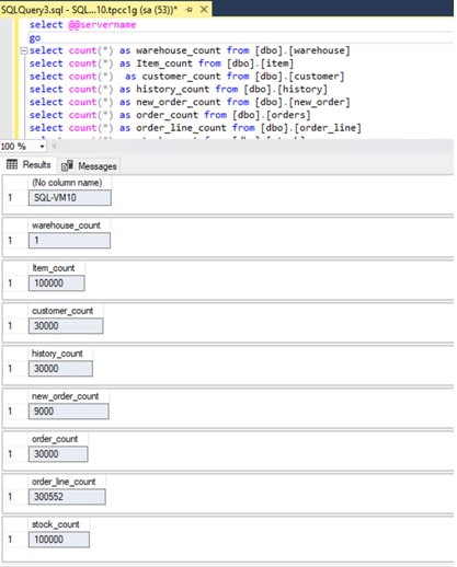
Step 2. Make sure SnapMirror replication is established between on-prem volume in FlexPod and CVO volume and relationship has healthy status. Wait for the data transfer to complete.
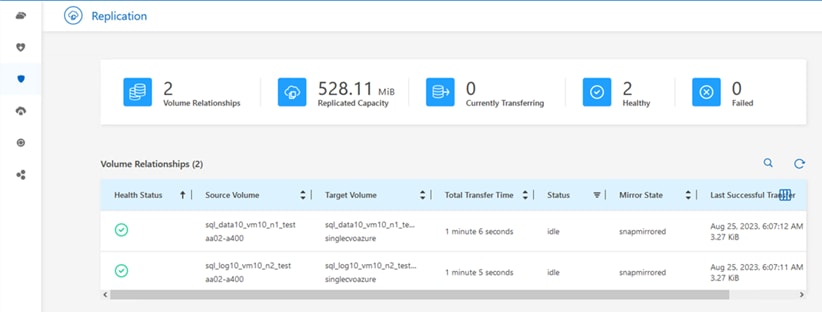
Step 3. Break the SnapMirror relationship between on-prem FlexPod and CVO and promote the CVO destination volumes to production. Perform this step for both data and log volumes.

After the SnapMirror relationship is broken, the CVO destination volume type changes from data protection (DP) to read/write (RW).
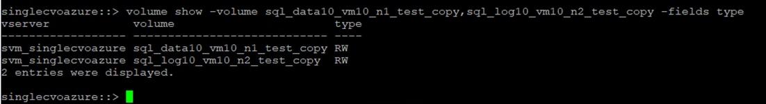
Step 4. Mount the data and log LUNs to Azure VM. This includes creating igroup on CVO using Azure VM iSCSI initiator IQN, mapping LUNs to the igroup, and discovering LUNs on Azure VM.

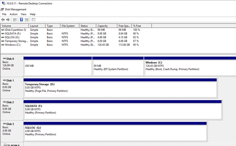
Step 5. Attach the SQL Database and run the script to get the row count of tpcc1g database on Azure VM.
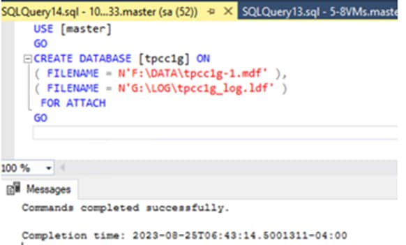
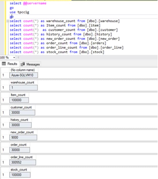
Step 6. Compare the row count values at both source (on-prem FlexPod) and destination (CVO). The row counts match, so we can infer that the data replication from the source to the destination has been completed successfully and the database integrity has been maintained.
Disaster Recovery (DR)
NetApp SnapMirror technology is used as a part of DR plans. If critical data is replicated to a different physical location, a serious disaster does not have to cause extended periods of data unavailability for business-critical applications. Clients can access replicated data across the network until the recovery of the production site from corruption, accidental deletion, natural disaster, and so on.
In the case of failback to the primary site, SnapMirror provides an efficient means of resynchronizing the DR site with the primary site, transferring only changed or new data back to the primary site from the DR site by simply reversing the SnapMirror relationship. After the primary production site resumes normal application operations, SnapMirror continues the transfer to the DR site without requiring another baseline transfer.
Procedure 1. Validate the Disaster Recovery
Step 1. Make sure that SnapMirror replication is already set up between the on-premises ONTAP in FlexPod instance and Cloud Volumes ONTAP in Azure, so that you can create frequent application snapshots.
Step 2. Simulate a disaster on the source (production) side by stopping the SQL-SVM that hosts the on-premises FlexPod volumes (both SQL data and log).
Step 3. Activate DR in CVO.
● Break the SnapMirror replication relationship between on-prem FlexPod and Cloud Volumes ONTAP and promote the CVO destination volumes (both SQL data and log) to production.
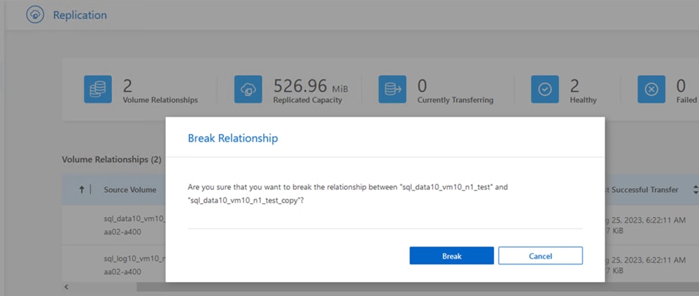
Note: Now CVO volumes are of type read/write (RW).
● Mount the CVO data and log LUNs to Azure VM. This shows that users can access replicated data across the network until the recovery of the production site from disaster.

● Reverse the SnapMirror relationship. This operation reverses the roles of the source and destination volumes.
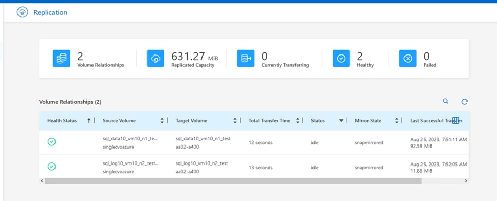
When this operation is performed, the contents from the original source volume are overwritten by the contents of the destination volume. This is helpful when you want to reactivate a source volume that went offline.
Now the CVO volumes becomes the source volumes, and the on-prem FlexPod volumes becomes the destination volumes.
Note: Any data written to the original source volume between the last data replication and the time that the source volume was disabled is not preserved.
● Verify write access to the CVO volumes. Let’s login to Azure VM in cloud and create a table as shown below.
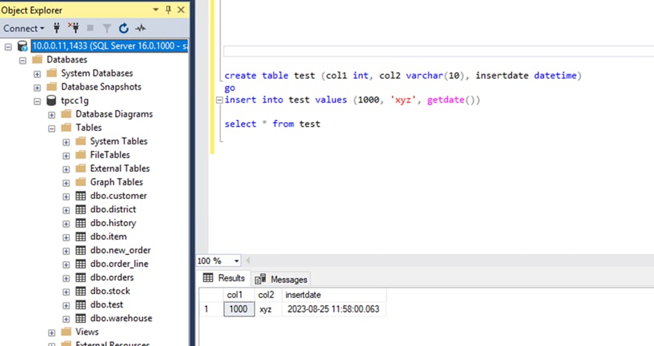
This shows that when the production site is down, clients can still access the data and also perform writes to the Cloud Volumes ONTAP volume, which is now the source volume.
This section illustrates the successful DR scenario when the production site is hit by disaster. Data can now be safely consumed by applications that can now serve the clients while the source site goes through restoration.
Verifying Data on Production Site (on-premises FlexPod)
After the production site is restored, you must make sure that the original configuration is restored, and clients are able to access the data from the source site.
This section details how to bring up the source site, restore the SnapMirror relationship between on-premises FlexPod and Cloud Volumes ONTAP, and perform a data integrity check on the source end.
Procedure 1. Verify the data on the production site (on-prem FlexPod)
Step 1. Make sure that the source site is now up. To do so, start the SVM that hosts the on-premises FlexPod volumes (data and log).
Step 2. Break the SnapMirror replication relationship between Cloud Volumes ONTAP and on-premises FlexPod and promote the on-premises volumes back to production.
After the SnapMirror relationship is broken, the on-premises volume type changes from data protection (DP) to read/write (RW).
Step 3. Reverse the SnapMirror relationship. Now, the on-premises FlexPod volumes become the source volumes as it were earlier, and the CVO volumes becomes the destination volumes.
By following these steps, you have successfully restored the original configuration.
Step 4. Restart the on-premises Windows VM and attach the SQL database. You notice that database is up-to-date here. The new table that you created on the Azure VM in cloud when production (on-prem FlexPod) was down, exists here as well.
You can infer that the data replication from the source to the destination has been completed successfully and that data integrity has been maintained. This completes the verification of data on the production site.
Conclusion
FlexPod is the optimal shared infrastructure foundation for deploying a variety of IT workloads. It is built on leading computing, networking, storage, and infrastructure software components. The FlexPod reference architecture discussed in this document is built with Cisco UCS X210c M7 blades powered by 4th generation Intel Scalable processors and NetApp AFF A400 storage array with the ONTAP 9.12.1 OS. It delivers the low-latency, consistent, and scalable database performance required by critical enterprise database workloads. With the NetApp SnapCenter data manageability tool, you can capture application consistent storage snapshots, avoiding the challenge of backup windows and gaining the capability to dynamically provision Dev/Test and business-continuity environments. Using SnapCenter, one can easily protect SQL workloads by performing backup, restore, and clone operations. NetApp Cloud Volume ONTAP (CVO) enables you to configure and achieve seamless disaster recovery of SQL Server databases by replicating the data from on-premises to cloud.
FlexPod provides highly efficient data lifecycle management and exceptional storage efficiency for SQL Server databases and logs. The performance tests detailed in this document demonstrate the robustness of the solution for hosting CPU and I/O-sensitive applications such as Microsoft SQL Server for database consolidation and peak storage I/O use cases. The performance and price comparison study between Cisco UCS B200 M5 and Cisco UCS X210c M7 compute platform provides a strong case for migration as two times SQL Database VMs can be consolidated at 22 percent cheaper cost as well associated benefits such licensing and power cost savings.
Gopu Narasimha Reddy, Technical Marketing Engineer, Cisco Systems, Inc.
Gopu Narasimha Reddy is a Technical Marketing engineer with the UCS Solutions team at Cisco. He is currently focused on validating and developing solutions on various Cisco UCS platforms for enterprise database workloads on different operating environments including Windows, VMware, Linux, and Kubernetes. Gopu is also involved in publishing database benchmarks on Cisco UCS servers. His areas of interest include building and validating reference architectures, development of sizing tools in addition to assisting customers in database deployments.
Kamini Singh, Technical Marketing Engineer, Hybrid Cloud Infra & OEM Solutions, NetApp, Inc.
Kamini Singh is a Technical Marketing engineer with FlexPod Solutions team at NetApp. She has more than four years of experience in data center infrastructure solutions. She focuses on FlexPod hybrid cloud infrastructure solution design, implementation, validation, automation, and sales enablement. Kamini holds a bachelor’s degree in Electronics and Communication and a master’s degree in Communication Systems.
Acknowledgements
For their support and contribution to the design, validation, and creation of this Cisco Validated Design, the authors would like to thank:
● John George, Technical Marketing Engineer, Cisco Systems, Inc.
● Vadi Bhatt, Principal Engineer, Cisco Systems, Inc.
● Babu Mahadevan, Technical Leader, Cisco Systems, Inc.
● John McAbel, Product Manager, Cisco Systems, Inc.
● Bobby Oommen, Sr. Manager FlexPod Solutions, NetApp
● Abhinav Singh, Sr. Technical Marketing Engineer, NetApp
● Sriram Sagi, Product Manager, NetApp
This appendix contains the following:
● Appendix A - Bill of Materials
● Appendix B - References used in this guide
Appendix A – Bill of Materials
This appendix contains the Bill of Materials.
Table 14 lists the Bill of Materials for Cisco UCS B200 M5 from the CCW estimate. Table 15 lists the Bill of Materials for Cisco UCS X210c M7 from the CCW estimate. All prices are shown in USD.
Table 14. Bill of Materials for Cisco UCS B200 M5
| Line Number |
Part Number |
Description |
Quantity |
Unit Net Price |
Extended Net Price |
| 1.0 |
UCSB-B200-M5-U |
UCS B200 M5 Blade w/o CPU, mem, HDD, mezz (UPG) |
1 |
4,223.08 |
4,223.08 |
| 1.0.1 |
CON-OSP-BB200M5U |
SNTC 24X7X4OS UCS B200 M5 Blade w/o CPU, mem, HDD, mezz (UPG |
1 |
948.00 |
948.00 |
| 1.1 |
UCS-MR-X32G2RW |
32GB RDIMM DRx4 3200 (8Gb) |
16 |
3,160.08 |
50,561.28 |
| 1.6 |
UCSB-MLOM-40G-04 |
Cisco UCS VIC 1440 modular LOM for Blade Servers |
1 |
1,646.62 |
1,646.62 |
| 1.8 |
N20-FW017 |
UCS 5108 Blade Chassis FW Package 4.1 |
1 |
0.00 |
0.00 |
| 1.9 |
UCS-SID-INFR-CFP |
Converged-FlexPod |
1 |
0.00 |
0.00 |
| 1.10 |
UCS-SID-WKL-MSFT |
Microsoft |
1 |
0.00 |
0.00 |
| 1.2 |
UCSB-LSTOR-BK |
FlexStorage blanking panels w/o controller, w/o drive bays |
2 |
0.00 |
0.00 |
| 1.3 |
UCSB-HS-M5-R |
CPU Heat Sink for UCS B-Series M5 CPU socket (Rear) |
1 |
0.00 |
0.00 |
| 1.5 |
UCSB-HS-M5-F |
CPU Heat Sink for UCS B-Series M5 CPU socket (Front) |
1 |
0.00 |
0.00 |
| 1.4 |
UCS-DIMM-BLK |
UCS DIMM Blanks |
8 |
0.00 |
0.00 |
| 1.7 |
UCS-CPU-I6248 |
Intel 6248 2.5GHz/150W 20C/27.5MB DCP DDR4 2933 MHz |
2 |
12,358.50 |
24,717.00 |
| 1.8 |
DC-MGT-IS-SAAS-ES |
Infrastructure Services SaaS/CVA - Essentials |
1 |
35.00 |
1,260.00 |
|
|
Total Price |
83,355.98 |
|||
Table 15. Bill of Materials for Cisco UCS X210c M7
| Line Number |
Part Number |
Description |
Quantity |
Unit Net Price |
Extended Net Price |
| 1.0 |
UCSX-M7-MLB |
UCSX M7 Modular Server and Chassis MLB |
1 |
0.00 |
0.00 |
| 1.1 |
DC-MGT-IS-SAAS-ES |
Infrastructure Services SaaS/CVA - Essentials |
1 |
35.00 |
1,260.00 |
| 1.2 |
UCSX-210C-M7-U |
UCS X210c M7 Compute Node 2S w/o CPU, Mem, Drv, Mezz |
1 |
6,344.66 |
6,344.66 |
| 1.2.0.1 |
CON-OSP-UCSX023C |
SNTC-24X7X4OS UCS X210c M7 Compute Node 2S w o CPU, Me |
1 |
1,761.00 |
1,761.00 |
| 1.2.1 |
UCSX-ML-V5D200G-D |
Cisco UCS VIC 15231 2x100G mLOM for X Compute Node |
1 |
1,740.00 |
1,740.00 |
| 1.2.2 |
UCSX-TPM-OPT-OUT-D |
OPT OUT, TPM 2.0, TCG, FIPS140-2, CC EAL4+ Certified |
1 |
0.00 |
0.00 |
| 1.2.3 |
UCSX-C-SW-LATEST-D |
Platform SW (Recommended) latest release X-Series ComputeNode |
1 |
0.00 |
0.00 |
| 1.2.4 |
UCSX-C-M7-HS-F |
UCS X210c M7 Compute Node Front CPU Heat Sink |
1 |
0.00 |
0.00 |
| 1.2.5 |
UCSX-C-M7-HS-R |
UCS X210c M7 Compute Node Rear CPU Heat Sink |
1 |
0.00 |
0.00 |
| 1.2.6 |
UCSX-X10C-FMBK-D |
UCS X10c Compute Node Front Mezz Blank |
1 |
0.00 |
0.00 |
| 1.2.7 |
UCSX-M2-HWRD-FPS |
UCSX Front panel with M.2 RAID controller for SATA drives |
1 |
0.00 |
0.00 |
| 1.2.8 |
UCS-DDR5-BLK |
UCS DDR5 DIMM Blanks |
16 |
0.00 |
0.00 |
| 1.2.9 |
UCSX-CPU-I6448H |
Intel I6448H 2.4GHz/250W 32C/60MB DDR5 4800MT/s |
2 |
10,268.00 |
20,536.00 |
| 1.2.10 |
UCSX-MRX32G1RE1 |
32GB DDR5-4800 RDIMM 1Rx4 (16Gb) |
16 |
2,283.00 |
36,528.00 |
| 1.2.11 |
UCS-SID-INFR-CFP-D |
Converged-FlexPod |
1 |
0.00 |
0.00 |
| 1.2.12 |
UCS-SID-WKL-MSFTD |
Microsoft |
1 |
0.00 |
0.00 |
|
|
Total Price |
68,169.66 |
|||
Appendix B – References used in this Guide
Cisco UCS Design Guides: https://www.cisco.com/c/en/us/solutions/design-zone.html
FlexPod Datacenter with Cisco UCS M7 IMM, VMware vSphere 8.0, and NetApp ONTAP 9.12 Design Guide: https://www.cisco.com/c/en/us/td/docs/unified_computing/ucs/UCS_CVDs/flexpod_m7_imm_vmware_design.html
FlexPod Datacenter with End-to-End 100G, IMM, using IaC, VMware 7U3, and NetApp 9.11: https://www.cisco.com/c/en/us/td/docs/unified_computing/ucs/UCS_CVDs/flexpod_iac_e2d_deploy.html
Cisco Intersight: https://www.intersight.com
Cisco Intersight Managed Mode: https://www.cisco.com/c/en/us/td/docs/unified_computing/Intersight/b_Intersight_Managed_Mode_Configuration_Guide.html
Cisco Unified Computing System: http://www.cisco.com/en/US/products/ps10265/index.html
Cisco UCS 6536 Fabric Interconnects: https://www.cisco.com/c/en/us/products/collateral/servers-unified-computing/ucs6536-fabric-interconnect-ds.html
Cisco Nexus 9000 Series Switches: http://www.cisco.com/c/en/us/products/switches/nexus-9000-series-switches/index.html
Cisco MDS 9132T Switches: https://www.cisco.com/c/en/us/products/collateral/storage-networking/mds-9100-series-multilayer-fabric-switches/datasheet-c78-739613.html
NetApp ONTAP: https://docs.netapp.com/ontap-9/index.jsp
NetApp Active IQ Unified Manager: https://community.netapp.com/t5/Tech-ONTAP-Blogs/Introducing-NetApp-Active-IQ-Unified-Manager-9-11/ba-p/435519
NetApp ONTAP Storage Connector for Cisco Intersight: https://www.netapp.com/pdf.html?item=/media/25001-tr-4883.pdf
NetApp ONTAP tools for VMware vSphere: https://docs.netapp.com/us-en/ontap-tools-vmware-vsphere/index.html
NetApp SnapCenter: https://docs.netapp.com/us-en/snapcenter/index.html
NetApp BlueXP: https://docs.netapp.com/us-en/bluexp-family/
NetApp Cloud Volumes ONTAP: https://docs.netapp.com/us-en/bluexp-cloud-volumes-ontap/
VMware vCenter Server: http://www.vmware.com/products/vcenter-server/overview.html
VMware vSphere: https://www.vmware.com/products/vsphere
Cisco UCS Hardware Compatibility Matrix: https://ucshcltool.cloudapps.cisco.com/public/
VMware and Cisco Unified Computing System: http://www.vmware.com/resources/compatibility
NetApp Interoperability Matrix Tool: http://support.netapp.com/matrix/
For comments and suggestions about this guide and related guides, join the discussion on Cisco Community at https://cs.co/en-cvds.
CVD Program
ALL DESIGNS, SPECIFICATIONS, STATEMENTS, INFORMATION, AND RECOMMENDATIONS (COLLECTIVELY, "DESIGNS") IN THIS MANUAL ARE PRESENTED "AS IS," WITH ALL FAULTS. CISCO AND ITS SUPPLIERS DISCLAIM ALL WARRANTIES, INCLUDING, WITHOUT LIMITATION, THE WARRANTY OF MERCHANTABILITY, FITNESS FOR A PARTICULAR PURPOSE AND NONINFRINGEMENT OR ARISING FROM A COURSE OF DEALING, USAGE, OR TRADE PRACTICE. IN NO EVENT SHALL CISCO OR ITS SUPPLIERS BE LIABLE FOR ANY INDIRECT, SPECIAL, CONSEQUENTIAL, OR INCIDENTAL DAMAGES, INCLUDING, WITHOUT LIMITATION, LOST PROFITS OR LOSS OR DAMAGE TO DATA ARISING OUT OF THE USE OR INABILITY TO USE THE DESIGNS, EVEN IF CISCO OR ITS SUPPLIERS HAVE BEEN ADVISED OF THE POSSIBILITY OF SUCH DAMAGES.
THE DESIGNS ARE SUBJECT TO CHANGE WITHOUT NOTICE. USERS ARE SOLELY RESPONSIBLE FOR THEIR APPLICATION OF THE DESIGNS. THE DESIGNS DO NOT CONSTITUTE THE TECHNICAL OR OTHER PROFESSIONAL ADVICE OF CISCO, ITS SUPPLIERS OR PARTNERS. USERS SHOULD CONSULT THEIR OWN TECHNICAL ADVISORS BEFORE IMPLE-MENTING THE DESIGNS. RESULTS MAY VARY DEPENDING ON FACTORS NOT TESTED BY CISCO.
CCDE, CCENT, Cisco Eos, Cisco Lumin, Cisco Nexus, Cisco StadiumVision, Cisco TelePresence, Cisco WebEx, the Cisco logo, DCE, and Welcome to the Human Network are trademarks; Changing the Way We Work, Live, Play, and Learn and Cisco Store are service marks; and Access Registrar, Aironet, AsyncOS, Bringing the Meeting To You, Catalyst, CCDA, CCDP, CCIE, CCIP, CCNA, CCNP, CCSP, CCVP, Cisco, the Cisco Certified Internetwork Expert logo, Cisco IOS, Cisco Press, Cisco Systems, Cisco Systems Capital, the Cisco Systems logo, Cisco Unified Computing System (Cisco UCS), Cisco UCS B-Series Blade Servers, Cisco UCS C-Series Rack Servers, Cisco UCS S-Series Storage Servers, Cisco UCS Manager, Cisco UCS Management Software, Cisco Unified Fabric, Cisco Application Centric Infrastructure, Cisco Nexus 9000 Series, Cisco Nexus 7000 Series. Cisco Prime Data Center Network Manager, Cisco NX-OS Software, Cisco MDS Series, Cisco Unity, Collaboration Without Limitation, EtherFast, EtherSwitch, Event Center, Fast Step, Follow Me Browsing, FormShare, GigaDrive, HomeLink, Internet Quotient, IOS, iPhone, iQuick Study, LightStream, Linksys, MediaTone, MeetingPlace, MeetingPlace Chime Sound, MGX, Networkers, Networking Academy, Network Registrar, PCNow, PIX, PowerPanels, ProConnect, ScriptShare, SenderBase, SMARTnet, Spectrum Expert, StackWise, The Fastest Way to Increase Your Internet Quotient, TransPath, WebEx, and the WebEx logo are registered trade-marks of Cisco Systems, Inc. and/or its affiliates in the United States and certain other countries. (LDW_P1)
All other trademarks mentioned in this document or website are the property of their respective owners. The use of the word partner does not imply a partnership relationship between Cisco and any other company. (0809R)