FlexPod Datacenter for SAP Solution using FibreChannel SAN with Cisco UCS Manager 4.0 and NetApp ONTAP 9.7
Available Languages
Bias-Free Language
The documentation set for this product strives to use bias-free language. For the purposes of this documentation set, bias-free is defined as language that does not imply discrimination based on age, disability, gender, racial identity, ethnic identity, sexual orientation, socioeconomic status, and intersectionality. Exceptions may be present in the documentation due to language that is hardcoded in the user interfaces of the product software, language used based on RFP documentation, or language that is used by a referenced third-party product. Learn more about how Cisco is using Inclusive Language.
- US/Canada 800-553-2447
- Worldwide Support Phone Numbers
- All Tools
 Feedback
 Feedback

FlexPod Datacenter for SAP Solution using FibreChannel SAN with Cisco UCS Manager 4.0 and NetApp ONTAP 9.7
Deployment Guide for FibreChannel-based FlexPod Datacenter Solution for SAP and SAP HANA with Cisco UCS 4th Generation and NetApp ONTAP 9.7
Published: December 2020
![]()
In partnership with:
![]()
About the Cisco Validated Design Program
The Cisco Validated Design (CVD) program consists of systems and solutions designed, tested, and documented to facilitate faster, more reliable, and more predictable customer deployments. For more information, go to:
http://www.cisco.com/go/designzone.
ALL DESIGNS, SPECIFICATIONS, STATEMENTS, INFORMATION, AND RECOMMENDATIONS (COLLECTIVELY, "DESIGNS") IN THIS MANUAL ARE PRESENTED "AS IS," WITH ALL FAULTS. CISCO AND ITS SUPPLIERS DISCLAIM ALL WARRANTIES, INCLUDING, WITHOUT LIMITATION, THE WARRANTY OF MERCHANTABILITY, FITNESS FOR A PARTICULAR PURPOSE AND NONINFRINGEMENT OR ARISING FROM A COURSE OF DEALING, USAGE, OR TRADE PRACTICE. IN NO EVENT SHALL CISCO OR ITS SUPPLIERS BE LIABLE FOR ANY INDIRECT, SPECIAL, CONSEQUENTIAL, OR INCIDENTAL DAMAGES, INCLUDING, WITHOUT LIMITATION, LOST PROFITS OR LOSS OR DAMAGE TO DATA ARISING OUT OF THE USE OR INABILITY TO USE THE DESIGNS, EVEN IF CISCO OR ITS SUPPLIERS HAVE BEEN ADVISED OF THE POSSIBILITY OF SUCH DAMAGES.
THE DESIGNS ARE SUBJECT TO CHANGE WITHOUT NOTICE. USERS ARE SOLELY RESPONSIBLE FOR THEIR APPLICATION OF THE DESIGNS. THE DESIGNS DO NOT CONSTITUTE THE TECHNICAL OR OTHER PROFESSIONAL ADVICE OF CISCO, ITS SUPPLIERS OR PARTNERS. USERS SHOULD CONSULT THEIR OWN TECHNICAL ADVISORS BEFORE IMPLEMENTING THE DESIGNS. RESULTS MAY VARY DEPENDING ON FACTORS NOT TESTED BY CISCO.
CCDE, CCENT, Cisco Eos, Cisco Lumin, Cisco Nexus, Cisco StadiumVision, Cisco TelePresence, Cisco WebEx, the Cisco logo, DCE, and Welcome to the Human Network are trademarks; Changing the Way We Work, Live, Play, and Learn and Cisco Store are service marks; and Access Registrar, Aironet, AsyncOS, Bringing the Meeting To You, Catalyst, CCDA, CCDP, CCIE, CCIP, CCNA, CCNP, CCSP, CCVP, Cisco, the Cisco Certified Internetwork Expert logo, Cisco IOS, Cisco Press, Cisco Systems, Cisco Systems Capital, the Cisco Systems logo, Cisco Unified Computing System (Cisco UCS), Cisco UCS B-Series Blade Servers, Cisco UCS C-Series Rack Servers, Cisco UCS S-Series Storage Servers, Cisco UCS Manager, Cisco UCS Management Software, Cisco Unified Fabric, Cisco Application Centric Infrastructure, Cisco Nexus 9000 Series, Cisco Nexus 7000 Series. Cisco Prime Data Center Network Manager, Cisco NX-OS Software, Cisco MDS Series, Cisco Unity, Collaboration Without Limitation, EtherFast, EtherSwitch, Event Center, Fast Step, Follow Me Browsing, FormShare, GigaDrive, HomeLink, Internet Quotient, IOS, iPhone, iQuick Study, LightStream, Linksys, MediaTone, MeetingPlace, MeetingPlace Chime Sound, MGX, Networkers, Networking Academy, Network Registrar, PCNow, PIX, PowerPanels, ProConnect, ScriptShare, SenderBase, SMARTnet, Spectrum Expert, StackWise, The Fastest Way to Increase Your Internet Quotient, TransPath, WebEx, and the WebEx logo are registered trademarks of Cisco Systems, Inc. and/or its affiliates in the United States and certain other countries.
All other trademarks mentioned in this document or website are the property of their respective owners. The use of the word partner does not imply a partnership relationship between Cisco and any other company. (0809R)
© 2020 Cisco Systems, Inc. All rights reserved.
Contents
Deployment Hardware and Software
System Provisioning for SAP HANA
Monitor SAP HANA with AppDynamics
Cisco and NetApp have partnered to deliver FlexPod, which serves as the foundation for a variety of SAP and SAP HANA workloads and enables efficient architectural designs that are based on customer requirements. FlexPod Datacenter solution is a validated approach for deploying Cisco and NetApp technologies as a shared infrastructure platform for SAP HANA implementation in Tailored DataCenter Integration (TDI) mode.
This document describes the Cisco and NetApp FlexPod Datacenter with NetApp ONTAP 9.7 on NetApp AFF A400 storage, Cisco UCS Manager unified software release 4.1(1) with 2nd Generation Intel Xeon Scalable Processors for SAP HANA in particular.
FlexPod Datacenter with NetApp ONTAP 9.7 and Cisco UCS unified software release 4.1(1) is a predesigned, best-practice datacenter architecture built on the Cisco Unified Computing System (Cisco UCS), the Cisco Nexus 9000 family of switches, MDS 9000 multilayer fabric switches, and NetApp AFF A-Series storage arrays running ONTAP 9.7 storage OS.
The current industry trend in datacenter design is towards shared infrastructures. With pre-validated IT platforms, enterprise customers have embarked on the journey to the cloud by moving away from application silos and toward shared infrastructure that can be quickly deployed, thereby increasing agility, and reducing costs.
Cisco and NetApp have partnered to deliver FlexPod, which uses best of breed storage, server, and network components to serve as the foundation for a variety of SAP workloads in general and SAP HANA in particular, enabling efficient architectural designs that can be quickly and confidently deployed.
The audience for this document includes, but is not limited to; sales engineers, field consultants, professional services, IT managers, partner engineers, and customers who want to take advantage of an infrastructure built to deliver IT efficiency and enable IT innovation.
This document provides a step-by-step configuration and implementation guide for the FlexPod Datacenter with Cisco UCS Fabric Interconnects, NetApp AFF storage, Cisco MDS, and Cisco Nexus 9000 solution.
The following design elements distinguish this version of FlexPod from previous FlexPod architectures:
● Cisco UCS 4.1(1) unified software release, Cisco UCS B480-M5 with 2nd Generation Intel Xeon Scalable Processors, and Cisco 1400 Series Virtual Interface Cards (VICs)
● Cisco UCS 6454 Fabric Interconnects
● Cisco UCS 2408 Fabric Extender
● Cisco Intersight Software as a Service (SaaS) Management
● NetApp AFF A400 Storage Controller
● NetApp ONTAP® 9.7
● NetApp SnapCenter and NetApp SnapCenter Plug-in for SAP HANA Version 4.3
● Fibre channel and NFS storage design
● Unified Extensible Firmware Interface (UEFI) Secure Boot with SLES for SAP Applications 15 SP2 and RHEL for SAP HANA 8.1 Operating Systems.
● 32 Gigabit per second Fibre Channel Connectivity
Deployment Hardware and Software
FlexPod is a defined set of hardware and software that serves as an integrated foundation for both virtualized and non-virtualized SAP HANA workloads. The FlexPod design is flexible enough that the networking, computing, and storage can fit in one data center rack or be deployed according to a customer's data center design. Port density enables the networking components to accommodate multiple configurations of this kind.
One benefit of the FlexPod architecture is the ability to customize or "flex" the environment to suit a customer's requirements. A FlexPod can easily be scaled as requirements and demand change. The unit can be scaled both up (adding resources to a FlexPod unit) and out (adding more FlexPod units). The reference architecture detailed in this document highlights the resiliency, cost benefit, and ease of deployment of a Fibre Channel and IP-based storage solution. A storage system capable of serving multiple protocols across a single interface allows for customer choice and investment protection because it truly is a wire-once architecture.
Figure 1 shows the VMware vSphere built on FlexPod components and the network connections for a configuration with the Cisco UCS 6454 Fabric Interconnects. This design has port-channeled 25 Gb Ethernet connections between the Cisco UCS 5108 Blade Chassis and the Cisco UCS Fabric Interconnects via the Cisco UCS 2408 Fabric Extenders, 25 Gb Ethernet connections between the Cisco UCS Fabric Interconnect and Cisco Nexus 9000, and between Cisco Nexus 9000 and NetApp AFF A400 storage array. This infrastructure option is expanded with Cisco MDS switches placed between the Cisco UCS Fabric Interconnect and the NetApp AFF A400 to provide FC-booted hosts with 32 Gb FC block-level access to storage serving them SAP HANA persistence as well.
Figure 1. FlexPod with Cisco UCS 6454 Fabric Interconnects and NetApp AFF A400
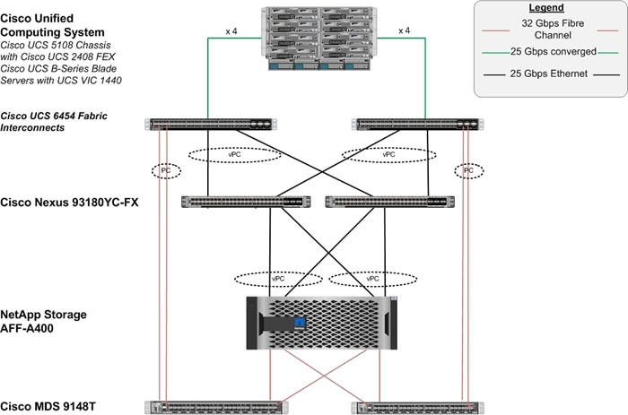
The reference architecture hardware configuration includes:
● Two Cisco Nexus 93180YC-FX switches
● Two Cisco UCS 6454 fabric interconnects
● Two Cisco MDS 9148T multilayer fabric switches
● One NetApp AFF 400 (HA pair) running ONTAP 9.7 with external NVMe Disk shelf NS224 SSD disks
Table 1 lists the software revisions for this solution.
| Layer |
Device |
Image |
Comments |
| Compute |
Cisco UCS Fabric Interconnects 6454, Cisco UCS B480 M5 and with 2nd Generation Intel Xeon Scalable Processors |
4.1(1d) |
Includes the Cisco UCS 2408 Fabric Extender, Cisco UCS Manager, Cisco UCS VIC 1440, and Cisco UCS VIC 1480 |
| Network |
Cisco Nexus 93180YC-FX NX-OS |
9.2(4) |
|
|
|
Cisco MDS 9148T |
8.4(1a) |
|
| Storage |
NetApp AFF 400 with NVMe NS224 external disk shelf |
ONTAP 9.7 |
|
| Software |
Cisco UCS Manager |
4.1(1d) |
|
| Management |
Cisco Intersight |
1.0.9-148 |
|
| Software |
Operating Systems |
SLES for SAP 15 SP2 and RHEL for SAP HANA 8.1 |
|
This document explains how to configure a fully redundant, highly available configuration for a FlexPod unit with ONTAP storage. Therefore, reference is made to which component is being configured with each step, either 01 or 02 or A and B. For example, node01 and node02 are used to identify the two NetApp storage controllers that are provisioned with this document, and Cisco Nexus A or Cisco Nexus B identifies the pair of Cisco Nexus switches that are configured. The Cisco UCS Fabric Interconnects are similarly configured. Additionally, this document details the steps for provisioning multiple Cisco UCS hosts, and these examples are identified as: HANA-scaleup-01, HANA-scaleout-01 etc to represent infrastructure hosts deployed to each of the fabric interconnects in this document. Finally, to indicate that you should include information pertinent to your environment in a given step, <text> appears as part of the command structure. See the following example for the network port vlan create command:
Usage:
network port vlan create ?
[-node] <nodename> Node
{ [-vlan-name] {<netport>|<ifgrp>} VLAN Name
| -port {<netport>|<ifgrp>} Associated Network Port
[-vlan-id] <integer> } Network Switch VLAN Identifier
Example:
network port vlan create -node <node01> -vlan-name a0a-<vlan id>
This document is intended to enable you to fully configure the customer environment. In this process, various steps require you to insert customer-specific naming conventions, IP addresses, and VLAN schemes, as well as to record appropriate MAC addresses. Table 2 describes the VLANs necessary for deployment as outlined in this guide.
| VLAN Name |
VLAN Purpose |
ID Used in Validating This Document |
| Out-of-Band Mgmt |
VLAN for out-of-band management interfaces |
75 |
| Native |
VLAN to which untagged frames are assigned |
2 |
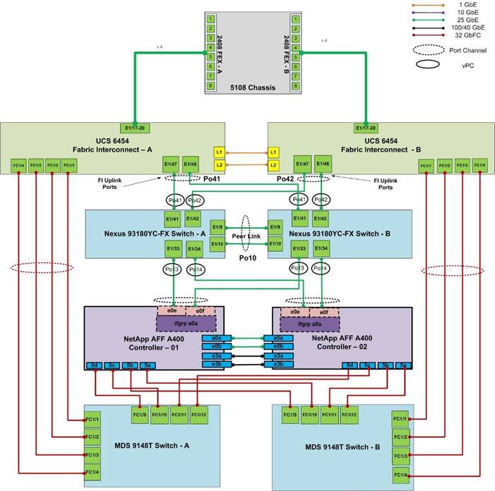
The information in this section is provided as a reference for cabling the physical equipment in a FlexPod environment. To simplify cabling requirements, a cabling diagram was used.
The cabling diagram in this section contains details for the prescribed and supported configuration of the NetApp AFF 400 running NetApp ONTAP® 9.7.
![]() For any modifications of this prescribed architecture, consult the NetApp Interoperability Matrix Tool (IMT).
For any modifications of this prescribed architecture, consult the NetApp Interoperability Matrix Tool (IMT).
This document assumes that out-of-band management ports are plugged into an existing management infrastructure at the deployment site. These interfaces will be used in various configuration steps.
The NetApp storage controller and disk shelves should be connected according to best practices for the specific storage controller and disk shelves. For disk shelf cabling, refer to NetApp Support.
Figure 2 details the cable connections used in the validation lab for the FlexPod topology based on the Cisco UCS 6454 fabric interconnect. Four 32Gb uplinks connect as port-channels to each Cisco UCS Fabric Interconnect from the MDS switches, and a total of eight 32Gb links connect the MDS switches to the NetApp AFF controllers. Also, 25Gb links connect the Cisco UCS Fabric Interconnects to the Cisco Nexus Switches and the NetApp AFF controllers to the Cisco Nexus Switches. Additional 1Gb management connections will be needed for an out-of-band network switch that sits apart from the FlexPod infrastructure. Each Cisco UCS fabric interconnect and Cisco Nexus switch is connected to the out-of-band network switch, and each AFF controller has a connection to the out-of-band network switch.
Figure 2. FlexPod Cabling with Cisco UCS 6454 Fabric Interconnect and NetApp AFF 400
This section provides a detailed procedure to configure the Cisco Nexus 9000s to use in a FlexPod environment.
![]() Follow the steps in this section precisely because failure to do so could result in an improper configuration.
Follow the steps in this section precisely because failure to do so could result in an improper configuration.
Follow the physical connectivity guidelines for FlexPod as explained in the section FlexPod Cabling.
The following procedures describe how to configure the Cisco Nexus switches for use in a base FlexPod environment. This procedure assumes you’re using Cisco Nexus 9000 7.0(3)I7(6), the Cisco suggested Nexus switch release at the time of this validation.
Table 3 lists the VLANs necessary for deployment as outlined in this guide.
Table 3. Configuration Variables
| Variable Name |
VLAN purpose |
Value used in Validation Setup |
| <nexus-A-hostname> |
Cisco Nexus A host name |
fp-nexus-A |
| <nexus-A-mgmt0-ip> |
Out-of-band management Cisco Nexus A IP address |
192.168.75.2 |
| <nexus-A-mgmt0-netmask> |
Out-of-band management network netmask |
255.255.255.0 |
| <nexus-A-mgmt0-gw> |
Out-of-band management network default gateway |
192.168.75.1 |
| <nexus-B-hostname> |
Cisco Nexus B host name |
fp-nexus-B |
| <nexus-B-mgmt0-ip> |
Out-of-band management Cisco Nexus B IP address |
192.168.75.3 |
| <nexus-B-mgmt0-netmask>> |
Out-of-band management network netmask |
255.255.255.0 |
| <nexus-B-mgmt0-gw> |
Out-of-band management network default gateway |
192.168.75.1 |
| <global-ntp-server-ip>> |
NTP server IP address |
192.168.75.19 |
| <nexus-vpc-domain-id>> |
Unique Cisco Nexus switch VPC domain ID |
10 |
| <hana-admin-vlan-id> |
HANA node administration VLAN |
75 |
| <hana-internode-vlan-id> |
HANA server-server communication network VLAN ID |
220 |
| <hana-backup-vlan-id> |
HANA node backup VLAN |
222 |
| <hana-client-vlan-id> |
Client Network for HANA VLAN ID |
223 |
| <hana-appserver-vlan-id> |
Application Server Network for HANA VLAN ID |
221 |
| <hana-datasource-vlan-id> |
Data source Network for HANA VLAN ID |
224 |
| <hana-replication-vlan-id> |
Replication Network for HANA VLAN ID |
225 |
| <hana-sharednfs-vlan-id> |
Shared NFS network for /hana/shared access |
228 |
Cisco Nexus A
To set up the initial configuration for the Cisco Nexus A switch on <nexus-A-hostname>, follow these steps:
1. Configure the switch.
On initial boot and connection to the serial or console port of the switch, the NX-OS setup should automatically start and attempt to enter Power on Auto Provisioning.
Abort Power On Auto Provisioning [yes - continue with normal setup, skip - bypass password and basic configuration, no - continue with Power On Auto Provisioning] (yes/skip/no)[no]: yes
Disabling POAP.......Disabling POAP
poap: Rolling back, please wait... (This may take 5-15 minutes)
---- System Admin Account Setup ----
Do you want to enforce secure password standard (yes/no) [y]: Enter
Enter the password for "admin": <password>
Confirm the password for "admin": <password>
Would you like to enter the basic configuration dialog (yes/no): yes
Create another login account (yes/no) [n]: Enter
Configure read-only SNMP community string (yes/no) [n]: Enter
Configure read-write SNMP community string (yes/no) [n]: Enter
Enter the switch name: <nexus-A-hostname>
Continue with Out-of-band (mgmt0) management configuration? (yes/no) [y]: Enter
Mgmt0 IPv4 address: <nexus-A-mgmt0-ip>
Mgmt0 IPv4 netmask: <nexus-A-mgmt0-netmask>
Configure the default gateway? (yes/no) [y]: Enter
IPv4 address of the default gateway: <nexus-A-mgmt0-gw>
Configure advanced IP options? (yes/no) [n]: Enter
Enable the telnet service? (yes/no) [n]: Enter
Enable the ssh service? (yes/no) [y]: Enter
Type of ssh key you would like to generate (dsa/rsa) [rsa]: Enter
Number of rsa key bits <1024-2048> [1024]: Enter
Configure the ntp server? (yes/no) [n]: y
NTP server IPv4 address: <global-ntp-server-ip>
Configure default interface layer (L3/L2) [L2]: Enter
Configure default switchport interface state (shut/noshut) [noshut]: shut
Configure CoPP system profile (strict/moderate/lenient/dense/skip) [strict]: Enter
Would you like to edit the configuration? (yes/no) [n]: Enter
2. Review the configuration summary before enabling the configuration.
Use this configuration and save it? (yes/no) [y]: Enter
Cisco Nexus B
To set up the initial configuration for the Cisco Nexus B switch on <nexus-B-hostname>, follow these steps:
1. Configure the switch.
![]() On initial boot and connection to the serial or console port of the switch, the NX-OS setup should automatically start and attempt to enter Power on Auto Provisioning.
On initial boot and connection to the serial or console port of the switch, the NX-OS setup should automatically start and attempt to enter Power on Auto Provisioning.
Abort Power On Auto Provisioning [yes - continue with normal setup, skip - bypass password and basic configuration, no - continue with Power On Auto Provisioning] (yes/skip/no)[no]: yes
Disabling POAP.......Disabling POAP
poap: Rolling back, please wait... (This may take 5-15 minutes)
---- System Admin Account Setup ----
Do you want to enforce secure password standard (yes/no) [y]: Enter
Enter the password for "admin": <password>
Confirm the password for "admin": <password>
Would you like to enter the basic configuration dialog (yes/no): yes
Create another login account (yes/no) [n]: Enter
Configure read-only SNMP community string (yes/no) [n]: Enter
Configure read-write SNMP community string (yes/no) [n]: Enter
Enter the switch name: <nexus-B-hostname>
Continue with Out-of-band (mgmt0) management configuration? (yes/no) [y]: Enter
Mgmt0 IPv4 address: <nexus-B-mgmt0-ip>
Mgmt0 IPv4 netmask: <nexus-B-mgmt0-netmask>
Configure the default gateway? (yes/no) [y]: Enter
IPv4 address of the default gateway: <nexus-B-mgmt0-gw>
Configure advanced IP options? (yes/no) [n]: Enter
Enable the telnet service? (yes/no) [n]: Enter
Enable the ssh service? (yes/no) [y]: Enter
Type of ssh key you would like to generate (dsa/rsa) [rsa]: Enter
Number of rsa key bits <1024-2048> [1024]: Enter
Configure the ntp server? (yes/no) [n]: y
NTP server IPv4 address: <global-ntp-server-ip>
Configure default interface layer (L3/L2) [L2]: Enter
Configure default switchport interface state (shut/noshut) [noshut]: shut
Configure CoPP system profile (strict/moderate/lenient/dense/skip) [strict]: Enter
Would you like to edit the configuration? (yes/no) [n]: Enter
2. Review the configuration summary before enabling the configuration.
Use this configuration and save it? (yes/no) [y]: Enter
FlexPod Cisco Nexus Switch Configuration
Cisco Nexus A and Cisco Nexus B
To license the Cisco Nexus switches, follow these steps:
1. Log in as admin.
2. Run the following commands to enable the required features:
config t
feature udld
feature interface-vlan
feature lacp
feature vpc
feature lldp
Cisco Nexus A and Cisco Nexus B
To create the necessary virtual local area networks (VLANs), follow this step on both switches:
1. From the global configuration mode, run the following commands:
vlan 75
name HANA-Node-Mgmt
vlan 220
name HANA-Internode
vlan 221
name HANA-AppServer
vlan 222
name HANA-Backup
vlan 223
name HANA-Client
vlan 224
name HANA-Datasource
vlan 225
name HANA-System-Replication
vlan 228
name HANA-sharednfs
exit
Create Port Channels and assign interfaces
Cisco Nexus A
To create the necessary port channels between devices, follow this step:
1. From the global configuration mode, run the following commands:
interface Po10
description vPC peer-link
interface Eth1/9-10
channel-group 10 mode active
no shutdown
interface Po13
description PC-NetApp-A
interface Eth1/33
description AFF-A4000-A:e0e
channel-group 13 mode active
no shutdown
interface Po14
description PC-NetApp-B
interface Eth1/34
description AFF-A400-B:e0e
channel-group 14 mode active
no shutdown
interface Po41
description PC-from-FI-A
interface Eth1/41
description FI-A:1/47
channel-group 41 mode active
no shutdown
interface Po42
description PC-from-FI-B
interface Eth1/42
description FI-B:1/47
channel-group 42 mode active
no shutdown
exit
copy run start
To create the necessary port channels between devices, follow this step:
1. From the global configuration mode, run the following commands:
interface Po10
description vPC peer-link
interface Eth1/9-10
channel-group 10 mode active
no shutdown
interface Po13
description PC-NetApp-A
interface Eth1/33
description AFF-A400-A:e0f
channel-group 13 mode active
no shutdown
interface Po14
description PC-NetApp-B
interface Eth1/34
description AFF-A400-B:e0f
channel-group 14 mode active
no shutdown
interface Po41
description PC-from-FI-A
interface Eth1/41
description FI-A:1/48
channel-group 41 mode active
no shutdown
interface Po42
description PC-from-FI-A
interface Eth1/42
description FI-B:1/48
channel-group 42 mode active
no shutdown
exit
copy run start
Configure Port Channel Parameters
Cisco Nexus A and Cisco Nexus B
To configure port channel parameters, follow this step on both switches:
1. From the global configuration mode, run the following commands:
interface Po10
description vPC peer-link
switchport mode trunk
switchport trunk allowed vlan 75,220-225,228
spanning-tree port type network
interface Po13
description PC-NetApp-A
switchport mode trunk
switchport trunk allowed vlan 228
spanning-tree port type edge trunk
mtu 9216
interface Po14
description PC-NetApp-B
switchport mode trunk
switchport trunk allowed vlan 228
spanning-tree port type edge trunk
mtu 9216
interface Po41
description PC-from-FI-A
switchport mode trunk
switchport trunk allowed vlan 75,220-225,228
spanning-tree port type edge trunk
mtu 9216
interface Po42
description PC-from-FI-B
switchport mode trunk
switchport trunk allowed vlan 75,220-225,228
spanning-tree port type edge trunk
mtu 9216
exit
copy run start
Configure Virtual Port Channels
Cisco Nexus A
To configure virtual port channels (vPCs) for switch A, follow this step:
1. From the global configuration mode, run the following commands:
vpc domain <nexus-vpc-domain-id>
role priority 10
peer-keepalive destination <nexus-B-mgmt0-ip> source <nexus-A-mgmt0-ip>
peer-switch
peer-gateway
auto-recovery
delay restore 150
interface Po10
vpc peer-link
interface Po13
vpc 13
interface Po14
vpc 14
interface Po41
vpc 41
interface Po42
vpc 42
exit
copy run start
Cisco Nexus B
To configure vPCs for switch B, follow this step:
1. From the global configuration mode, run the following commands:
vpc domain <nexus-vpc-domain-id>
role priority 20
peer-keepalive destination <nexus-A-mgmt0-ip> source <nexus-B-mgmt0-ip>
peer-switch
peer-gateway
auto-recovery
delay restore 150
interface Po10
vpc peer-link
interface Po13
vpc 13
interface Po14
vpc 14
interface Po41
vpc 41
interface Po42
vpc 42
exit
copy run start
Uplink into Existing Network Infrastructure
Depending on the available network infrastructure, several methods and features can be used to uplink the FlexPod environment. If an existing Cisco Nexus environment is present, it is recommended to use vPCs to uplink the Cisco Nexus switches included in the FlexPod environment into the infrastructure. Use this procedure to create an uplink vPC to the existing environment. Make sure to run copy run start to save the configuration on each switch after the configuration is completed.
Complete Configuration Worksheet
Before running the setup script, complete the cluster setup worksheet and review the configuration worksheets in the ONTAP 9.7 Software Setup Guide to learn about configuring ONTAP software.
Table 4 and Table 5 list the information needed to configure two ONTAP nodes. Customize the cluster detail values with the information applicable to your deployment.
Table 4. ONTAP Software Installation Prerequisites
| Cluster Detail |
Cluster Detail Value |
Value used in validation setup |
| Cluster node 01 IP address |
<node01-mgmt-ip> |
192.168.75.29 |
| Cluster node 01 netmask |
<node01-mgmt-mask> |
255.255.255.0 |
| Cluster node 01 gateway |
<node01-mgmt-gateway> |
192.168.75.1 |
| Cluster node 02 IP address |
<node02-mgmt-ip> |
192.168.75.30 |
| Cluster node 02 netmask |
<node02-mgmt-mask> |
255.255.255.0 |
| Cluster node 02 gateway |
<node02-mgmt-gateway> |
192.168.75.1 |
| Data ONTAP 9.7 URL |
<url-boot-software> |
|
Table 5 lists all the parameters required to set up the ONTAP cluster.
Table 5. ONTAP Cluster Prerequisites
| Cluster Detail |
Cluster Detail Value |
Values used in validation setup |
| Cluster name |
aff_a400 |
|
| ONTAP base license |
<cluster-base-license-key> |
|
| NFS license key |
<nfs-license-key> |
|
| FCP license key |
<iscsi-license-key> |
|
| NetApp SnapRestore® license key |
<snaprestore-license-key> |
|
| NetApp SnapVault® license key |
<snapvault-license-key> |
|
| NetApp SnapMirror® license key |
<snapmirror-license-key> |
|
| NetApp FlexClone® license key |
<flexclone-license-key> |
|
| Cluster management IP address |
<clustermgmt-ip> |
192.168.75.31 |
| Cluster management netmask |
<clustermgmt-mask> |
255.255.255.0 |
| Cluster management gateway |
<clustermgmt-gateway> |
192.168.75.1 |
| Node 01 service processor IP address |
<node01-SP-ip> |
|
| Node 01 service processor IP netmask |
<node01-SP-mask> |
|
| Node 01 service processor IP gateway |
<node01-SP-gateway> |
|
| Node 02 service processor IP address |
<node02-SP-ip> |
|
| Node 02 service processor IP netmask |
<node02-SP-mask> |
|
| DNS domain name |
<dns-domain-name> |
|
| DNS server IP address |
<dns-ip> |
192.168.75.19 |
| Time zone |
<timezone> |
|
| NTP server IP address |
<ntp-ip> |
192.168.75.19 |
| SNMP contact information |
<snmp-contact> |
|
| SNMP location |
<snmp-location> |
|
| DFM server or another fault management server FQDN to receive SNMP traps |
<oncommand-um-server-fqdn> |
|
| SNMPv1 community string |
<snmp-community> |
|
| Mail host to send NetApp AutoSupport® messages |
<mailhost> |
|
| Storage admin email for NetApp AutoSupport |
<storage-admin-email> |
|
To set up an ONTAP cluster, follow these steps:
1. From a console port program attached to the storage controller A (node 01) console port, run the node setup script. This script appears when ONTAP 9.7 software boots on the node for the first time.
2. Follow the prompts to set up node 01:
Welcome to node setup.
You can enter the following commands at any time:
"help" or "?" - if you want to have a question clarified,
"back" - if you want to change previously answered questions, and
"exit" or "quit" - if you want to quit the setup wizard.
Any changes you made before quitting will be saved.
You can return to cluster setup at any time by typing “cluster setup”.
To accept a default or omit a question, do not enter a value.
This system will send event messages and weekly reports to NetApp Technical Support.
To disable this feature, enter "autosupport modify -support disable" within 24 hours.
Enabling AutoSupport can significantly speed problem determination and resolution should a problem occur on your system.
For further information on AutoSupport, see:
http://support.netapp.com/autosupport/
Type yes to confirm and continue {yes}: yes
Enter the node management interface port [e0M]: Enter
Enter the node management interface IP address: <node01-mgmt-ip>
Enter the node management interface netmask: <node01-mgmt-mask>
Enter the node management interface default gateway: <node01-mgmt-gateway>
A node management interface on port e0M with IP address <node01-mgmt-ip> has been created
Use your web browser to complete cluster setup by accessing https://<node01-mgmt-ip>
Otherwise press Enter to complete cluster setup using the command line interface:
![]() Cluster setup can also be done using NetApp System Manager. This document describes the cluster setup using the CLI guided setup.
Cluster setup can also be done using NetApp System Manager. This document describes the cluster setup using the CLI guided setup.
3. Press Enter to continue the cluster setup via CLI.
4. Create a new cluster:
Do you want to create a new cluster or join an existing cluster? {create, join}:
Create
5. Press Enter for the default option “no” to setup a single node cluster:
Do you intend for this node to be used as a single node cluster? {yes, no} [no]:
6. Create the cluster interface configuration. Choose Yes if you want to use the default settings.
Existing cluster interface configuration found:
Port MTU IP Netmask
e3a 9000 169.254.142.30 255.255.0.0
e3b 9000 169.254.41.219 255.255.0.0
Do you want to use this configuration? {yes, no} [yes]:
7. Provide the cluster administrator’s password:
Enter the cluster administrator's (username "admin") password:
Retype the password:
8. Create the cluster and provide a cluster name :
Step 1 of 5: Create a Cluster
You can type "back", "exit", or "help" at any question.
Enter the cluster name: <clustername>
Creating cluster <clustername>
.
Starting replication service
Starting replication service .
Starting replication service ..
System start up
System start up .
System start up ..
System start up ...
System start up ....
System start up .....
Updating LIF Manager
Vserver Management
Starting cluster support services
Starting cluster support services .
Starting cluster support services ..
Cluster <clustername> has been created.
9. Add the necessary license keys:
Step 2 of 5: Add Feature License Keys
You can type "back", "exit", or "help" at any question.
Enter an additional license key []:
10. Create the vserver for cluster administration:
Step 3 of 5: Set Up a Vserver for Cluster Administration
You can type "back", "exit", or "help" at any question.
Enter the cluster management interface port [e0e]: e0M
Enter the cluster management interface IP address: <clustermgmt-ip>
Enter the cluster management interface netmask: <clustermgmt-mask>
Enter the cluster management interface default gateway [<clustermgmt-gateway>]:
A cluster management interface on port e0M with IP address <clustermgmt-ip> has been created. You can use this address to connect to and manage the cluster.
11. Provide the DNS domain names and DNS server IP address:
Enter the DNS domain names: <dns-domain-name>
Enter the DNS server IP addresses: <dns-ip>
12. Finish the first part of the setup:
Step 4 of 5: Configure Storage Failover (SFO)
You can type "back", "exit", or "help" at any question.
SFO will be enabled when the partner joins the cluster.
Step 5 of 5: Set Up the Node
You can type "back", "exit", or "help" at any question.
Where is the controller located []: <snmp-location>
Cluster "<clustername>" has been created.
To complete cluster setup, you must join each additional node to the cluster
by running "system node show-discovered" and "cluster add-node" from a node in the cluster.
To complete system configuration, you can use either OnCommand System Manager
or the Data ONTAP command-line interface.
To access OnCommand System Manager, point your web browser to the cluster
management IP address (https:// <clustermgmt-ip>).
To access the command-line interface, connect to the cluster management
IP address (for example, ssh admin@<clustermgmt-ip>).
13. From a console port program attached to the storage controller B (node 02) console port, run the node setup script. This script appears when ONTAP 9.7 software boots on the node for the first time.
14. Follow the prompts to set up node 02:
Welcome to the cluster setup wizard.
You can enter the following commands at any time:
"help" or "?" - if you want to have a question clarified,
"back" - if you want to change previously answered questions, and
"exit" or "quit" - if you want to quit the cluster setup wizard.
Any changes you made before quitting will be saved.
You can return to cluster setup at any time by typing "cluster setup".
To accept a default or omit a question, do not enter a value.
This system will send event messages and periodic reports to NetApp Technical
Support. To disable this feature, enter
autosupport modify -support disable
within 24 hours.
Enabling AutoSupport can significantly speed problem determination and
resolution, should a problem occur on your system.
For further information on AutoSupport, see:
http://support.netapp.com/autosupport/
Type yes to confirm and continue {yes}: yes
Enter the node management interface port [e0M]: Enter
Enter the node management interface IP address: <node02-mgmt-ip>
Enter the node management interface netmask: <node02-mgmt-mask>
Enter the node management interface default gateway: <node02-mgmt-gateway>
A node management interface on port e0M with IP address <node02-mgmt-ip> has been created
Use your web browser to complete cluster setup by accessing https://<node02-mgmt-ip>
Use your web browser to complete cluster setup by accessing
https://192.168.75.30
Otherwise, press Enter to complete cluster setup using the command line
interface:
15. Press Enter to continue the cluster setup via CLI.
16. Join the new cluster:
Do you want to create a new cluster or join an existing cluster? {create, join}:
join
17. Create the cluster interface configuration. Choose Yes if you want to use the default settings:
Existing cluster interface configuration found:
Port MTU IP Netmask
e3a 9000 169.254.57.171 255.255.0.0
e3b 9000 169.254.79.119 255.255.0.0
Do you want to use this configuration? {yes, no} [yes]:
18. Enter an IP address of the private cluster network from node 1:
Step 1 of 3: Join an Existing Cluster
You can type "back", "exit", or "help" at any question.
Enter the IP address of an interface on the private cluster network from the
cluster you want to join: 169.254.142.30
Joining cluster at address 169.254.142.30
.
Joining cluster
Joining cluster .
System start up
System start up .
System start up ..
System start up ...
System start up ....
System start up .....
Starting cluster support services
This node has joined the cluster <clustername>.
19. Finish the second part of the setup:
Step 2 of 3: Configure Storage Failover (SFO)
You can type "back", "exit", or "help" at any question.
SFO will be enabled when the partner joins the cluster.
Step 3 of 3: Set Up the Node
You can type "back", "exit", or "help" at any question.
This node has been joined to cluster "<clustername>".
To complete cluster setup, you must join each additional node to the cluster
by running "system node show-discovered" and "cluster add-node" from a node in the cluster.
To complete system configuration, you can use either OnCommand System Manager
or the Data ONTAP command-line interface.
To access OnCommand System Manager, point your web browser to the cluster
management IP address (https:// <clustermgmt-ip>).
To access the command-line interface, connect to the cluster management
IP address (for example, ssh admin@<clustermgmt-ip>).
20. Open an SSH connection to either the cluster IP or host name.
21. Log in with the admin user with the password you provided earlier.
Set Auto-Revert on Cluster Management
To set the auto-revert parameter on the cluster management interface, run the following command:
network interface modify –vserver <clustername> -lif cluster_mgmt –auto-revert true
![]() A storage virtual machine (SVM) is referred to as a Vserver (or vserver) in the GUI and CLI.
A storage virtual machine (SVM) is referred to as a Vserver (or vserver) in the GUI and CLI.
Set Up Management Broadcast Domain
By default, all network ports are included in the default broadcast domain. Network ports used for data services (for example, e0d, e1a, and e1e) should be removed from the default broadcast domain, leaving just the management network ports (e0M).
To make the changes, the following commands must be executed for each storage node. Storage nodes are named after the cluster name with an appended number.
broadcast-domain remove-ports –broadcast-domain Default –ports <clustername>1:e0f,<clustername>-1:e0e, <clustername>-2:e0f,<clustername>-2:e0e
broadcast-domain show
![]() Advanced Data Partitioning (ADPv2) creates a root partition and two data partitions on each SSD drive in an All Flash FAS configuration. Disk auto assign should assign one data partition to each node in a high availability pair.
Advanced Data Partitioning (ADPv2) creates a root partition and two data partitions on each SSD drive in an All Flash FAS configuration. Disk auto assign should assign one data partition to each node in a high availability pair.
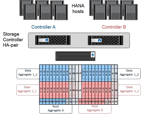
An aggregate containing the root volume for each storage controller is created during the ONTAP software setup process. To create additional aggregates, determine the aggregate name, the node on which to create it, and the number of disks it should contain.
To create new aggregates, run the following commands:
aggr create -aggregate aggr1_1 -node <clustername>-1 -diskcount 11
aggr create -aggregate aggr1_2 -node <clustername>-2 -diskcount 11
aggr create -aggregate aggr2_1 -node <clustername>-1 -diskcount 11
aggr create -aggregate aggr2_2 -node <clustername>-2 -diskcount 11
![]() Use all disks except for two spares to create the aggregates. In this example, 11 disks per aggregate were used.
Use all disks except for two spares to create the aggregates. In this example, 11 disks per aggregate were used.
![]() The aggregate cannot be created until the disk zeroing completes. Run the aggr show command to display aggregate creation status. Do not proceed until all are online.
The aggregate cannot be created until the disk zeroing completes. Run the aggr show command to display aggregate creation status. Do not proceed until all are online.
Optional: Rename the root aggregate on node 01 to match the naming convention for this aggregate on node 02. The aggregate is automatically renamed if system-guided setup is used.
aggr show
aggr rename –aggregate aggr0 –newname <node01-rootaggrname>
To confirm that storage failover is enabled, run the following commands for a failover pair:
1. Verify the status of storage failover.
storage failover show
![]() Both <clustername>_1 and <clustername>_2 must be capable of performing a takeover. Continue with step 3 if the nodes are capable of performing a takeover.
Both <clustername>_1 and <clustername>_2 must be capable of performing a takeover. Continue with step 3 if the nodes are capable of performing a takeover.
2. Enable failover on one of the two nodes.
storage failover modify -node <clustername>-1 -enabled true
![]() Enabling failover on one node enables it for both nodes.
Enabling failover on one node enables it for both nodes.
3. Verify the HA status for a two-node cluster.
![]() This step is not applicable for clusters with more than two nodes.
This step is not applicable for clusters with more than two nodes.
cluster ha show
4. Continue with step 6 if high availability is configured.
5. Only enable HA mode for two-node clusters. Do not run this command for clusters with more than two nodes because it causes problems with failover.
cluster ha modify -configured true
Do you want to continue? {y|n}: y
6. Verify that hardware assist is correctly configured and, if needed, modify the partner IP address.
storage failover hwassist show
storage failover modify –hwassist-partner-ip <node02-mgmt-ip> -node <clustername>-1
storage failover modify –hwassist-partner-ip <node01-mgmt-ip> -node <clustername>-2
Verify FCP Ports are Set to Target Ports
To change the FCP to target mode if they are configured as initiator, follow these steps:
1. Check the ports if they configured correctly:
aff_a400::system node hardware unified-connect show
Current Current Pending Pending Admin
Node Adapter Mode Type Mode Type Status
------------ ------- ------- --------- ------- --------- -----------
<clustername>-01 5a fc initiator - - online
<clustername>-01 5b fc initiator - - online
<clustername>-01 5c fc initiator - - online
<clustername>-01 5d fc initiator - - online
<clustername>-02 5a fc initiator - - online
<clustername>-02 5b fc initiator - - online
<clustername>-02 5c fc initiator - - online
<clustername>-02 5d fc initiator - - online
8 entries were displayed.
2. Disable all ports which need to be changed:
system node run -node <clustername>-01 -command storage disable adapter 5a
system node run -node <clustername>-01 -command storage disable adapter 5b
system node run -node <clustername>-01 -command storage disable adapter 5c
system node run -node <clustername>-01 -command storage disable adapter 5d
system node run -node <clustername>-02 -command storage disable adapter 5a
system node run -node <clustername>-02 -command storage disable adapter 5b
system node run -node <clustername>-02 -command storage disable adapter 5c
system node run -node <clustername>-02 -command storage disable adapter 5d
3. Change the HBAs mode to target:
ucadmin modify -node <clustername>-* -adapter 5a -type target
Warning: FC-4 type on adapter 5b will also be changed to target.
Do you want to continue? {y|n}: y
Any changes will take effect after rebooting the system. Use the "system node reboot" command to reboot.
Any changes will take effect after rebooting the system. Use the "system node reboot" command to reboot.
2 entries were modified.
ucadmin modify -node <clustername>-* -adapter 5c -type target
Warning: FC-4 type on adapter 5d will also be changed to target.
Do you want to continue? {y|n}: y
Any changes will take effect after rebooting the system. Use the "system node reboot" command to reboot.
Any changes will take effect after rebooting the system. Use the "system node reboot" command to reboot.
2 entries were modified.
4. Reboot each controller node:
node reboot -node <clustername>-01
5. Wait until the first node is back up and running and reboot the second node:
node reboot -node <clustername>-01
Disable Flow Control on 25/40/100GbE Ports
NetApp recommends disabling flow control on all the 25/40/100GbE ports that are connected to external devices. To disable flow control, follow these steps:
1. Run the following commands to configure node 1:
network port modify -node <clustername>_1 -port e0e,e0f -flowcontrol-admin none
Warning: Changing the network port settings will cause a several second interruption in carrier.
Do you want to continue? {y|n}: y
2. Run the following commands to configure node 2:
network port modify -node <clustername>_2 -port e0e,e0f -flowcontrol-admin none
Warning: Changing the network port settings will cause a several second interruption in carrier.
Do you want to continue? {y|n}: y
network port show –fields flowcontrol-admin
NetApp AutoSupport® sends support summary information to NetApp through HTTPS. To configure AutoSupport, run the following command:
system node autosupport modify -node * -state enable –mail-hosts <mailhost> -transport https -support enable -noteto <storage-admin-email>
Enable Cisco Discovery Protocol
To enable the Cisco Discovery Protocol (CDP) on the NetApp storage controllers, run the following command:
node run -node * options cdpd.enable on
![]() To be effective, CDP must also be enabled on directly connected networking equipment such as switches and routers.
To be effective, CDP must also be enabled on directly connected networking equipment such as switches and routers.
Create Broadcast Domain for NFS access
For this setup, the VLAN ID 228 has been used for NFS access which is needed for /hana/shared for SAP HANA multiple host setups.
The broadcast domains must be created with an MTU size of 9000 (jumbo frames):
broadcast-domain create -broadcast-domain NFS -mtu 9000
To create the LACP interface groups for the 25GbE data interfaces, run the following commands:
ifgrp create -node <clustername>_1 -ifgrp a0a -distr-func port -mode multimode_lacp
ifgrp add-port -node <clustername>_1 -ifgrp a0a -port e0e
ifgrp add-port -node <clustername>-_1 -ifgrp a0a -port e0f
ifgrp create -node <clustername>_2 -ifgrp a0a -distr-func port -mode multimode_lacp
ifgrp add-port -node <clustername>_2 -ifgrp a0a -port e0e
ifgrp add-port -node <clustername>_2 -ifgrp a0a -port e0f
ifgrp show
Create VLAN for NFS access
To create VLANs, follow these steps:
1. Set the MTU size of the interface groups.
network port modify –node <clustername>_1 -port a0a –mtu 9000
network port modify –node <clustername>_2 -port a0a –mtu 9000
2. Create HANA NFS VLAN ports and add them to the NFS broadcast domain.
network port vlan create –node <clustername>_1 -vlan-name a0a-<hana-sharednfs-vlan-id>
network port vlan create –node <clustername>_2 -vlan-name a0a-<hana-sharednfs-vlan-id>
broadcast-domain add-ports -broadcast-domain NFS -ports <clustername>-1:a0a-<hana-sharednfs-vlan-id>, <clustername>-02:a0a-<hana-sharednfs-vlan-id>
For each of the SVMs and the cluster node, create a certificate to allow secure communication with HTTPS. For each of the certificates, specify the individual values listed in Table 6.
Table 6. ONTAP Software Parameters Needed to Enable HTTPS
| Cluster Detail |
Cluster Detail Value |
| Certificate common name |
<cert-common-name> |
| Country code |
<cert-country> |
| State |
<cert-state> |
| Locality |
<cert-locality> |
| Organization |
<cert-org> |
| Unit |
<cert-unit> |
| |
<cert-email> |
| Number of days the certificate is valid |
<cert-days> |
To configure secure access to the storage controller, follow these steps:
1. Increase the privilege level to access the certificate commands.
set -privilege diag
Do you want to continue? {y|n}: y
2. Generally, a self-signed certificate is already in place. Verify the certificate and obtain parameters (for example the <serial-number>) by running the following command:
security certificate show
3. For each SVM shown, the certificate common name should match the DNS FQDN of the SVM. Delete the two default certificates and replace them with either self-signed certificates or certificates from a certificate authority (CA). To delete the default certificates, run the following commands:
security certificate delete -vserver hana-svm -common-name hana-svm -ca hana-svm -type server -serial <serial-number>
![]() Deleting expired certificates before creating new certificates is a best practice. Run the security certificate delete command to delete the expired certificates. In the following command, use tab completion to select and delete each default certificate.
Deleting expired certificates before creating new certificates is a best practice. Run the security certificate delete command to delete the expired certificates. In the following command, use tab completion to select and delete each default certificate.
4. To generate and install self-signed certificates, run the following commands as one-time commands. Generate a server certificate for the Infra-SVM, the HANA SVM, and the cluster SVM. Use tab completion to aid in the completion of these commands.
security certificate create -common-name <cert-common-name> -type server -size 2048 -country <cert-country> -state <cert-state> -locality <cert-locality> -organization <cert-org> -unit <cert-unit> -email-addr <cert-email> -expire-days <cert-days> -protocol SSL -hash-function SHA256 -vserver hana-svm
security certificate create -common-name <cert-common-name> -type server -size 2048 -country <cert-country> -state <cert-state> -locality <cert-locality> -organization <cert-org> -unit <cert-unit> -email-addr <cert-email> -expire-days <cert-days> -protocol SSL -hash-function SHA256 -vserver infra-svm
security certificate create -common-name <cert-common-name> -type server -size 2048 -country <cert-country> -state <cert-state> -locality <cert-locality> -organization <cert-org> -unit <cert-unit> -email-addr <cert-email> -expire-days <cert-days> -protocol SSL -hash-function SHA256 -vserver <clustername>
5. To obtain the values for the parameters required in the next step (<cert-ca> and <cert-serial>), run the security certificate show command.
6. Enable each certificate that was just created by using the –server-enabled true and –client-enabled false parameters. Use tab completion to aid in the completion of these commands.
security ssl modify -vserver <clustername> -server-enabled true -client-enabled false -ca <cert-ca> -serial <cert-serial> -common-name <cert-common-name>
security ssl modify -vserver hana-svm -server-enabled true -client-enabled false -ca <cert-ca> -serial <cert-serial> -common-name <cert-common-name>
security ssl modify -vserver infra-svm -server-enabled true -client-enabled false -ca <cert-ca> -serial <cert-serial> -common-name <cert-common-name>
7. Disable HTTP cluster management access.
system services firewall policy delete -policy mgmt -service http –vserver <clustername>
![]() It is normal for some of these commands to return an error message stating that the entry does not exist.
It is normal for some of these commands to return an error message stating that the entry does not exist.
8. Change back to the normal admin privilege level and set up the system so that SVM logs are available through the web.
set –privilege admin
vserver services web modify –name spi|ontapi|compat –vserver * -enabled true
Configure SVM for the Infrastructure
Table 7 and Figure 3 describe the infrastructure SVM together with all required storage objects (volumes and LIFs).
Figure 3. Overview of Infrastructure SVM Components
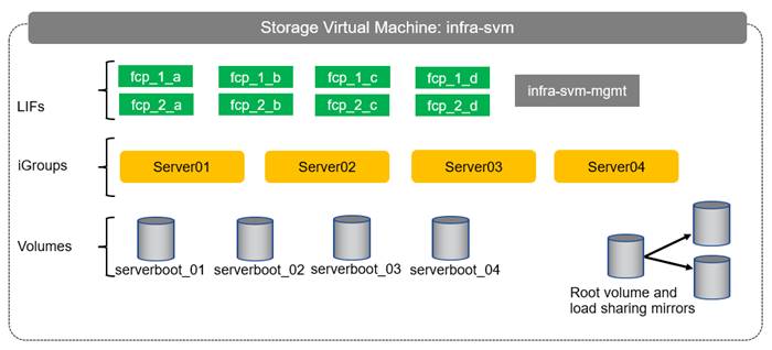
Table 7. ONTAP Software Parameters for Infrastructure SVMs
| Cluster Detail |
Cluster Detail Value |
Value used in validation setup |
| Infrastructure SVM management IP |
<infra-svm-ip> |
192.168.75.46 |
| Infrastructure SVM management IP netmask |
<infra-svm-netmask> |
255.255.255.0 |
| Infrastructure SVM default gateway |
<infra-svm-gateway> |
192.168.75.1 |
Create SVM for the Infrastructure
To create an infrastructure SVM, follow these steps:
1. Run the vserver create command.
vserver create –vserver infra-svm –rootvolume infra_rootvol –aggregate aggr2_1 –rootvolume-security-style unix
2. Select the SVM data protocols to configure, keeping iSCSI and NFS.
vserver remove-protocols –vserver infra-svm -protocols iscsi,nfs,cifs,nvme
3. Add the data aggregates to the SVM aggregate list.
vserver modify –vserver infra-svm –aggr-list aggr1_1,aggr2_1,aggr1_2,aggr2_2
4. Enable and run the NFS protocol in the SVM.
nfs create -vserver infra-svm -udp disabled
To create a load-sharing mirror of an SVM root volume, follow these steps:
1. Create a volume to be the load-sharing mirror of the infrastructure SVM root volume on each node.
volume create –vserver infra-svm –volume infra_rootvol_m01 –aggregate aggr2_1 –size 1GB –type DP
volume create –vserver infra-svm –volume infra_rootvol_m02 –aggregate aggr2_2 –size 1GB –type DP
2. Create the mirroring relationships.
snapmirror create –source-path infra-svm:infra_rootvol –destination-path
infra-svm:infra_rootvol_m01 –type LS -schedule 5min
snapmirror create –source-path infra-svm:infra_rootvol –destination-path
infra-svm:infra_rootvol_m02 –type LS -schedule 5min
3. Initialize the mirroring relationship.
snapmirror initialize-ls-set –source-path infra-svm:infra_rootvol
snapmirror show
Add Infrastructure SVM Management LIF
To add the infrastructure SVM administration LIF in the out-of-band management network, follow these steps:
1. Run the following commands:
network interface create –vserver infra-svm –lif infra-svm-mgmt -service-policy default-management –role data –data-protocol none –home-node <clustername>_2 -home-port e0M –address <infra-svm-ip> -netmask <infra-svm-mask> -status-admin up –failover-policy broadcast-domain-wide –firewall-policy mgmt –auto-revert true
![]() The SVM management IP in this step should be in the same subnet as the storage cluster management IP.
The SVM management IP in this step should be in the same subnet as the storage cluster management IP.
2. Create a default route to allow the SVM management interface to reach the outside world.
network route create –vserver infra-svm -destination 0.0.0.0/0 –gateway <infra-svm-gateway>
To create the eight FCP LIFs (four on each node), run the following commands:
net interface create -vserver infra-svm -lif fcp_2_a -data-protocol fcp -role data -home-node <clustername>-02 -home-port 5a
net interface create -vserver infra-svm -lif fcp_2_b -data-protocol fcp -role data -home-node <clustername>-02 -home-port 5b
net interface create -vserver infra-svm -lif fcp_2_c -data-protocol fcp -role data -home-node <clustername>-02 -home-port 5c
net interface create -vserver infra-svm -lif fcp_2_d -data-protocol fcp -role data -home-node <clustername>-02 -home-port 5d
net interface create -vserver infra-svm -lif fcp_1_a -data-protocol fcp -role data -home-node <clustername>-01 -home-port 5a
net interface create -vserver infra-svm -lif fcp_1_b -data-protocol fcp -role data -home-node <clustername>-01 -home-port 5b
net interface create -vserver infra-svm -lif fcp_1_c -data-protocol fcp -role data -home-node <clustername>-01 -home-port 5c
net interface create -vserver infra-svm -lif fcp_1_d -data-protocol fcp -role data -home-node <clustername>-01 -home-port 5d
Create Block Protocol (FCP) Service
Run the following command to create the FCP service. This command also starts the iSCSI service.
fcp create -vserver infra-svm
To create FlexVol volumes, run the following commands:
volume create -vserver infra-svm -volume serverboot -aggregate aggr1_1 -size 1000GB -state online -space-guarantee none -percent-snapshot-space 0
snapmirror update-ls-set -source-path infra-svm:infra_rootvol
Create Boot LUNs for Servers
To create boot LUNs, run the following commands. This example creates boot LUNs for four servers. Repeat the command with a different LUN name to create additional boot LUNs for additional servers.
lun create -vserver infra-svm -volume server_boot -lun server-01 -size 100G -ostype Linux -space-reserve disabled
lun create -vserver infra-svm -volume server_boot -lun server-02 -size 100G -ostype Linux -space-reserve disabled
lun create -vserver infra-svm -volume server_boot -lun server-03 -size 100G -ostype Linux -space-reserve disabled
lun create -vserver infra-svm -volume server_boot -lun server-04 -size 100G -ostype Linux -space-reserve disabled
Create Portset
To create a portset that includes four FCP LIFs, run the following commands:
portset create -vserver infra-svm -portset boot -protocol fcp -port-name fcp_1_a,fcp_1_c,fcp_2_a,fcp_2_c
Create igroups
![]() Use the WWPN information you defined in section Create WWPN Pools to create the igroups.
Use the WWPN information you defined in section Create WWPN Pools to create the igroups.
To create igroups, run the following commands:
igroup create –vserver infra-svm –igroup server-01 –protocol fcp –ostype linux –initiator <server-host-01-wwpns> -portset boot
igroup create –vserver infra-svm –igroup server-02 –protocol fcp –ostype linux –initiator <server-host-02-wwpns> -portset boot
igroup create –vserver infra-svm –igroup server-03 –protocol fcp –ostype linux –initiator <server-host-03-wwpns> -portset boot
igroup create –vserver infra-svm –igroup server-04 –protocol fcp –ostype linux –initiator <server-host-04-wwpns> -portset boot
Repeat the command by using the WWPNs of additional servers to create additional igroups for additional servers.
Map Boot LUNs to igroups
To map server boot LUNs to igroups, run the following commands. Repeat this command to map additional boot LUNs to additional servers.
lun map -vserver infra-svm -volume server_boot -lun server-01 -igroup server-01 -lun-id 0
lun map -vserver infra-svm -volume server_boot -lun server-02 -igroup server-02 -lun-id 0
lun map -vserver infra-svm -volume server_boot -lun server-03 -igroup server-03 -lun-id 0
lun map -vserver infra-svm -volume server_boot -lun server-04 -igroup server-04 -lun-id 0
Table 8 and Figure 4 describe the HANA SVM together with all the required storage objects (volumes, export-policies, and LIFs).
Figure 4. Overview of SAP HANA SVM Components
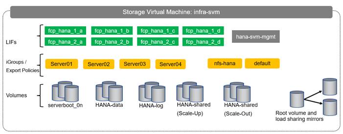
Table 8. ONTAP Software Parameter for HANA SVM
| Cluster Detail |
Cluster Detail Value |
Value used in CVD setup |
| HANA SVM management IP |
<hana-svm-ip> |
192.168.75.47 |
| HANA SVM management IP netmask |
<hana-svm-netmask> |
255.255.255.0 |
| HANA SVM default gateway |
<hana-svm-gateway> |
192.168.75.1 |
| NFS Shared CIDR |
<data-cidr> |
192.168.228.0 |
| NFS Shared netmask |
<data-netmask> |
255.255.255.0 |
| NFS shared LIF node 1 IP |
<node01-sharednfs_lif01-ip> |
192.168.228.21 |
| NFS shared LIF node 2 IP |
<node02-sharednfs_lif02-ip> |
192.168.228.22 |
To create an SVM for SAP HANA volumes, follow these steps:
1. Run the vserver create command.
vserver create –vserver hana-svm –rootvolume hana_rootvol –aggregate aggr1_2 –rootvolume-security-style unix
2. Select the SVM data protocols to configure, keeping NFS and FCP.
vserver remove-protocols –vserver hana-svm -protocols cifs,iscsi,nvme
3. Add the two data aggregates to the hana-svm aggregate list.
vserver modify –vserver hana-svm –aggr-list aggr1_1,aggr1_2,aggr2_1,aggr2_2
4. Disable any QOS policy at the vserver level
vserver modify -vserver hana-svm -qos-policy-group none
5. Enable and run the NFS protocol in the Infra-SVM.
nfs create -vserver hana-svm -v3 enabled
6. Enable a large NFS transfer size.
set advanced
vserver nfs modify –vserver hana-svm –tcp-max-transfersize 1048576
set admin
7. Set the group ID of the user root to 0.
vserver services unix-user modify -vserver hana-svm -user root -primary-gid 0
To create a load-sharing mirror of an SVM root volume, follow these steps:
1. Create a volume to be the load-sharing mirror of the HANA SVM root volume on each node.
volume create –vserver hana-svm –volume hana_rootvol_m01 –aggregate aggr2_1 –size 1GB –type DP
volume create –vserver hana-svm –volume hana_rootvol_m02 –aggregate aggr2_2 –size 1GB –type DP
2. Create the mirroring relationships.
snapmirror create –source-path hana-svm:hana_rootvol –destination-path hana-svm:hana_rootvol_m01 –type LS -schedule 5min
snapmirror create –source-path hana-svm:hana_rootvol –destination-path hana-svm:hana_rootvol_m02 –type LS -schedule 5min
3. Initialize the mirroring relationship.
snapmirror initialize-ls-set –source-path hana-svm:hana_rootvol
Create Export Policies for the Root Volumes
To configure the NFS export policies on the SVM, follow these steps:
1. Create a new rule for the infrastructure NFS subnet in the default export policy.
vserver export-policy rule create –vserver hana-svm -policyname default –ruleindex 1 –protocol nfs -clientmatch 0.0.0.0/0 -rorule sys –rwrule sys -superuser sys –allow-suid true
2. Assign the FlexPod export policy to the infrastructure SVM root volume.
volume modify –vserver hana-svm –volume hana_rootvol –policy default
Add HANA SVM Management Interface and Administrator
To add the HANA SVM administrator and SVM administration LIF in the out-of-band management network, follow these steps:
1. Run the following commands:
network interface create –vserver hana-svm –lif hana-svm-mgmt -service-policy default-management –role data –data-protocol none –home-node <clustername>-02 -home-port e0M –address <hana-svm-ip> -netmask <hana-svm-netmask> -status-admin up –failover-policy broadcast-domain-wide –firewall-policy mgmt –auto-revert true
![]() The SVM management IP in this step should be in the same subnet as the storage cluster management IP.
The SVM management IP in this step should be in the same subnet as the storage cluster management IP.
2. Create a default route to allow the SVM management interface to reach the outside world.
network route create –vserver hana-svm -destination 0.0.0.0/0 –gateway <hana-svm-gateway>
3. Set a password for the SVM vsadmin user and unlock the user.
security login password –username vsadmin –vserver hana-svm
Enter a new password: <password>
Enter it again: <password>
security login unlock –username vsadmin –vserver hana-svm
Create Export Policies for the HANA SVM
1. Create a new export policy for the HANA data and log subnet.
vserver export-policy create -vserver hana-svm -policyname nfs-hana
2. Create a rule for this policy.
vserver export-policy rule create -vserver hana-svm -policyname nfs-hana -clientmatch <data-cidr>,<log-cidr> -rorule sys -rwrule sys -allow-suid true -allow-dev true -ruleindex 1 -protocol nfs -superuser sys
Create NFS LIF for SAP HANA Shared
To create the NFS LIFs for SAP HANA data, run the following commands:
network interface create -vserver hana-svm -lif data-01 -role data -data-protocol nfs -home-node <clustername>-01 -home-port a0a-<hana-sharednfs-vlan-id> –address <node01-sharednfs_lif01-ip> -netmask <data-netmask> -status-admin up –failover-policy broadcast-domain-wide –firewall-policy data –auto-revert true
network interface create -vserver hana-svm -lif data-02 -role data -data-protocol nfs -home-node <clustername>-02 -home-port a0a-<hana-sharednfs-vlan-id> –address <node02-sharednfs_lif02-ip> -netmask <data-netmask> -status-admin up –failover-policy broadcast-domain-wide –firewall-policy data –auto-revert true
To create the eight FCP LIFs (four on each node), run the following commands:
net interface create -vserver hana-svm -lif fcp_hana_2_a -data-protocol fcp -role data -home-node <clustername>-02 -home-port 5a
net interface create -vserver hana-svm -lif fcp_hana_2_b -data-protocol fcp -role data -home-node <clustername>-02 -home-port 5b
net interface create -vserver hana-svm -lif fcp_hana_2_c -data-protocol fcp -role data -home-node <clustername>-02 -home-port 5c
net interface create -vserver hana-svm -lif fcp_hana_2_d -data-protocol fcp -role data -home-node <clustername>-02 -home-port 5d
net interface create -vserver hana-svm -lif fcp_hana_1_a -data-protocol fcp -role data -home-node <clustername>-01 -home-port 5a
net interface create -vserver hana-svm -lif fcp_hana_1_b -data-protocol fcp -role data -home-node <clustername>-01 -home-port 5b
net interface create -vserver hana-svm -lif fcp_hana_1_c -data-protocol fcp -role data -home-node <clustername>-01 -home-port 5c
net interface create -vserver hana-svm -lif fcp_hana_1_d -data-protocol fcp -role data -home-node <clustername>-01 -home-port 5d
Create Portset
To create a portset that includes all FCP LIFs, run the following commands:
portset create -vserver hana-svm -portset all_ports -protocol fcp -port-name fcp_hana_1_a,fcp_hana_1_b,fcp_hana_1_c,fcp_hana_1_d,fcp_hana_2_a,fcp_hana_2_b,fcp_hana_2_c,fcp_hana_2_d
Create igroups for SAP HANA Servers
Use the WWPN information you defined in section Create WWPN Pools to create the igroups.
To create igroups, run the following commands. Repeat this command by using the WWPNs of additional servers to create additional igroups for additional servers.
igroup create –vserver hana-svm –igroup server-01 –protocol fcp –ostype linux –initiator <server-host-01-wwpns> -portset all_ports
igroup create –vserver hana-svm –igroup server-02 –protocol fcp –ostype linux –initiator <server-host-02-wwpns> -portset all_ports
igroup create –vserver hana-svm –igroup server-03 –protocol fcp –ostype linux –initiator <server-host-03-wwpns> -portset all_ports
igroup create –vserver hana-svm –igroup server-04 –protocol fcp –ostype linux –initiator <server-host-04-wwpns> -portset all_ports
Cisco UCS Base Configuration
This FlexPod deployment explains the configuration steps for the Cisco UCS 6454 Fabric Interconnects (FI) in a design that will support Fibre Channel SAN boot.
![]() If setting up a system with iSCSI boot, the sections with (FCP) in the heading can be skipped and then complete section Cisco UCS Backup in the Appendix.
If setting up a system with iSCSI boot, the sections with (FCP) in the heading can be skipped and then complete section Cisco UCS Backup in the Appendix.
Perform Initial Setup of Cisco UCS 6454 Fabric Interconnects for FlexPod Environments
This section provides the detailed procedures for configuring the Cisco Unified Computing System (Cisco UCS) for use in a FlexPod environment. The steps are necessary to provision the Cisco UCS B-Series and C-Series servers and should be followed precisely to avoid improper configuration.
Cisco UCS Fabric Interconnect A
To configure the Cisco UCS for use in a FlexPod environment, follow these steps:
1. Connect to the console port on the first Cisco UCS fabric interconnect.
Enter the configuration method. (console/gui) ? console
Enter the setup mode; setup newly or restore from backup. (setup/restore) ? setup
You have chosen to setup a new Fabric interconnect. Continue? (y/n): y
Enforce strong password? (y/n) [y]: Enter
Enter the password for "admin": <password>
Confirm the password for "admin": <password>
Is this Fabric interconnect part of a cluster(select 'no' for standalone)? (yes/no) [n]: y
Enter the switch fabric (A/B) []: A
Enter the system name: <ucs-cluster-name>
Physical Switch Mgmt0 IP address : <ucsa-mgmt-ip>
Physical Switch Mgmt0 IPv4 netmask : <ucsa-mgmt-mask>
IPv4 address of the default gateway : <ucsa-mgmt-gateway>
Cluster IPv4 address : <ucs-cluster-ip>
Configure the DNS Server IP address? (yes/no) [n]: y
DNS IP address : <dns-server-1-ip>
Configure the default domain name? (yes/no) [n]: y
Default domain name : <ad-dns-domain-name>
Join centralized management environment (UCS Central)? (yes/no) [n]: Enter
Apply and save the configuration (select 'no' if you want to re-enter)? (yes/no): yes
Cisco UCS Fabric Interconnect B
To configure the Cisco UCS for use in a FlexPod environment, follow these steps:
1. Connect to the console port on the second Cisco UCS fabric interconnect.
Enter the configuration method. (console/gui) ? console
Installer has detected the presence of a peer Fabric interconnect. This Fabric interconnect will be added to the cluster. Continue (y/n) ? y
Enter the admin password of the peer Fabric interconnect: <password>
Connecting to peer Fabric interconnect... done
Retrieving config from peer Fabric interconnect... done
Peer Fabric interconnect Mgmt0 IPv4 Address: <ucsa-mgmt-ip>
Peer Fabric interconnect Mgmt0 IPv4 Netmask: <ucsa-mgmt-mask>
Cluster IPv4 address : <ucs-cluster-ip>
Peer FI is IPv4 Cluster enabled. Please Provide Local Fabric Interconnect Mgmt0 IPv4 Address
Physical Switch Mgmt0 IP address : <ucsb-mgmt-ip>
Local fabric interconnect model(UCS-FI-6454)
Peer fabric interconnect is compatible with the local fabric interconnect. Continuing with the installer...
Apply and save the configuration (select 'no' if you want to re-enter)? (yes/no): yes
2. Wait for the login prompt for the Cisco UCS Fabric Interconnect B before proceeding to the next section.
Cisco UCS Setup
To log into the Cisco Unified Computing System (Cisco UCS) environment, follow these steps:
1. Open a web browser and navigate to the Cisco UCS fabric interconnect cluster address.
![]() You may need to wait at least 5 minutes after configuring the second fabric interconnect for Cisco UCS Manager to open.
You may need to wait at least 5 minutes after configuring the second fabric interconnect for Cisco UCS Manager to open.
2. Click the Launch UCS Manager link to launch Cisco UCS Manager.
3. If prompted to accept security certificates, accept as necessary.
4. When prompted, enter admin for the user name and enter the administrative password.
5. Click Login to log into Cisco UCS Manager.
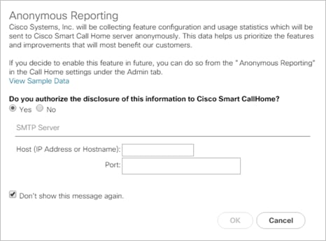
To enable anonymous reporting, follow this step:
1. In the Anonymous Reporting window, choose whether to send anonymous data to Cisco for improving future products. If you choose Yes, enter the IP address of your SMTP Server. Click OK.
Upgrade Cisco UCS Manager Software to Version 4.1(1d)
This document assumes you’re using Cisco UCS 4.1(1d). To upgrade the Cisco UCS Manager software and the Cisco UCS Fabric Interconnect software to version 4.1(1d), refer to Cisco UCS Manager Install and Upgrade Guides.
To synchronize the Cisco UCS environment to the NTP servers in the Cisco Nexus switches, follow these steps:
1. In Cisco UCS Manager, click Admin.
2. Expand All > Time Zone Management.
3. Choose Timezone.
4. In the Properties pane, choose the appropriate time zone in the Timezone menu.
5. Click Save Changes and then click OK.
6. Click Add NTP Server.
7. Enter <nexus-A-mgmt0-ip> and click OK. Click OK to confirm.
![]() We used the Cisco Nexus switch mgmt0 interface IP because it is in the same L2 domain as the UCS mgmt0 IPs. We could also use the Cisco Nexus NTP IPs, but that traffic would then have to pass through an L3 router.
We used the Cisco Nexus switch mgmt0 interface IP because it is in the same L2 domain as the UCS mgmt0 IPs. We could also use the Cisco Nexus NTP IPs, but that traffic would then have to pass through an L3 router.
8. Click Add NTP Server.
9. Enter <nexus-B-mgmt0-ip> and click OK, then click OK again.
To add one or more additional DNS servers to the UCS environment, follow these steps:
1. In Cisco UCS Manager, click Admin.
2. Expand All > Communications Management.
3. Choose DNS Management.
4. In the Properties pane, choose Specify DNS Server.
5. Enter the IP address of the additional DNS server.
6. Click OK and then click OK again. Repeat this process for any additional DNS servers.
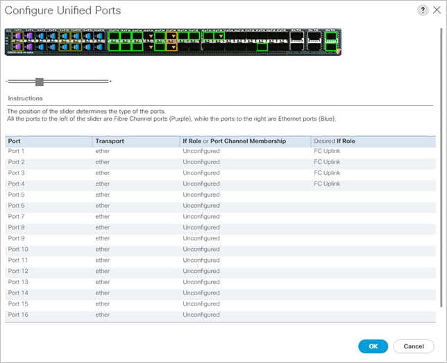
Configure Unified Ports (FCP)
Fibre Channel port configurations differ between the Cisco UCS 6454, 6332-16UP and the 6248UP fabric interconnects. All fabric interconnects have a slider mechanism within the Cisco UCS Manager GUI interface, but the fibre channel port selection options for the Cisco UCS 6454 are from the first 16 ports starting from the first port and configured in increments of 4 ports from the left. For the Cisco UCS 6332-16UP the port selection options are from the first 16 ports starting from the first port, and configured in increments of the first 6, 12, or all 16 of the unified ports. With the 6248UP, the port selection options will start from the right of the 32 fixed ports, or the right of the 16 ports of the expansion module, going down in contiguous increments of 2. The remainder of this section shows configuration of the 6454. Modify as necessary for the Cisco UCS 6332-16UP or 6248UP.
To enable the fibre channel ports, follow these steps for the Cisco UCS 6454:
1. In Cisco UCS Manager, click Equipment.
2. Choose Equipment > Fabric Interconnects > Fabric Interconnect B (subordinate).
3. Choose Configure Unified Ports.
4. Click Yes in the pop-up window warning that changes to the fixed module will require a reboot of the fabric interconnect and changes to the expansion module will require a reboot of that module.
5. Within the Configured Fixed Ports pop-up window move the gray slider bar from the left to the right to choose either 4, 8, 12, or 16 ports to be set as FC Uplinks.
6. Click OK, then click Yes, then click OK to continue.
7. Choose Equipment > Fabric Interconnects > Fabric Interconnect A (primary).
8. Choose Configure Unified Ports.
9. Click Yes on the pop-up window warning that changes to the fixed module will require a reboot of the fabric interconnect and changes to the expansion module will require a reboot of that module.
10. Within the Configured Fixed Ports pop-up window move the gray slider bar from the left to the right to choose either 4 or 8 ports to be set as FC Uplinks.
11. Click OK, then click Yes, then OK to continue.
12. Wait for both Fabric Interconnects to reboot.
13. Log back into Cisco UCS Manager.
Setting the discovery policy simplifies the addition of Cisco UCS B-Series chassis and of additional fabric extenders for further Cisco UCS C-Series connectivity. To modify the chassis discovery policy, follow these steps:
1. In Cisco UCS Manager, click Equipment and choose the Policies tab.
2. Under Global Policies, set the Chassis/FEX Discovery Policy to match the minimum number of ports that are cabled between the chassis or fabric extenders (FEXes) and the fabric interconnects.
![]() If varying numbers of links between chassis and the Fabric Interconnects will be used, set Action set to 2 Link, the minimum recommended number of links for a FlexPod.
If varying numbers of links between chassis and the Fabric Interconnects will be used, set Action set to 2 Link, the minimum recommended number of links for a FlexPod.
3. On the Cisco UCS 6454 Fabric Interconnects, the Link Grouping Preference is automatically set to Port Channel and is greyed out. On a Cisco UCS 6300 Series or Cisco UCS 6200 Series Fabric Interconnect, set the Link Grouping Preference to Port Channel. If Backplane Speed Preference appears, leave it set at 40G.
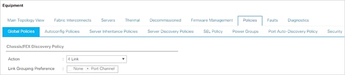
4. If any changes have been made, click Save Changes, and then click OK.
Enable Port Auto-Discovery Policy
Setting the port auto-discovery policy enables automatic discovery of Cisco UCS B-Series chassis server ports. To modify the port auto-discovery policy, follow these steps:
1. In Cisco UCS Manager, click Equipment, choose All > Equipment in the Navigation Pane, and choose the Policies tab.
2. Under Port Auto-Discovery Policy, set Auto Configure Server Port to Enabled.
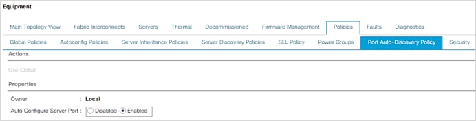
3. Click Save Changes and then click OK.
Enable Server and Uplink Ports
To enable and verify server and uplink ports, follow these steps:
1. In Cisco UCS Manager, click Equipment.
2. Expand Equipment > Fabric Interconnects > Fabric Interconnect A (primary) > Fixed Module.
3. Expand and choose Ethernet Ports.
4. Verify that all ports connected to UCS chassis are configured as Server ports and have a status of Up.
5. Click Yes to confirm server ports and click OK.
6. Verify that the ports connected to the chassis are now configured as server ports.
7. Choose the ports that are connected to the Cisco Nexus switches, right-click them, and choose Configure as Uplink Port.
8. Click Yes to confirm uplink ports and click OK.
9. Choose Equipment > Fabric Interconnects > Fabric Interconnect B (subordinate) > Fixed Module.
10. Expand and choose Ethernet Ports.
11. Verify that all ports connected to UCS chassis are configured as Server ports and have a status of Up.
12. Click Yes to confirm server ports and click OK.
13. Verify that the ports connected to the chassis are now configured as server ports.
14. Choose the ports that are connected to the Cisco Nexus switches, right-click them, and choose Configure as Uplink Port.
15. Click Yes to confirm the uplink ports and click OK.
Enable Info Policy for Neighbor Discovery
Enabling the info policy enables Fabric Interconnect neighbor information to be displayed. To modify the info policy, follow these steps:
1. In Cisco UCS Manager, click Equipment, choose All > Equipment in the Navigation Pane, and choose the Policies tab on the right.
2. Under Global Policies, scroll down to Info Policy and choose Enabled for Action.

3. Click Save Changes and then click OK.
4. Under Equipment, choose Fabric Interconnect A or B. On the right, choose the Neighbors tab. CDP information is shown under the LAN tab and LLDP information is shown under the LLDP tab.
Acknowledge Cisco UCS Chassis and FEX
To acknowledge all Cisco UCS chassis and any external FEX modules, follow these steps:
1. In Cisco UCS Manager, click Equipment.
2. Expand Chassis and choose each chassis that is listed.
3. Right-click each chassis and choose Acknowledge Chassis.
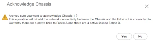
4. Click Yes and then click OK to complete acknowledging the chassis.
5. If Nexus FEXes are part of the configuration, expand Rack Mounts and FEX.
6. Right-click each FEX that is listed and choose Acknowledge FEX.
7. Click Yes and then click OK to complete acknowledging the FEX.
Now all items have been deployed at the root level in Cisco UCS Manager. To allow this Cisco UCS to be shared among different projects, UCS Organizations can be created. In this validation, the organization for this FlexPod deployment is FlexPod. To create an organization for this FlexPod deployment, follow these steps:
1. In Cisco UCS Manager, click Servers.
2. In the Navigation Pane, expand Servers > Service Profiles.
3. Right-click root under Service Profiles and choose Create Organization.
4. Provide a name for the Organization to indicate this FlexPod deployment and optionally provide a Description.
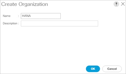
5. Click OK then click OK again to complete creating the organization.
Create a WWNN Pool for FC Boot (FCP)
In this FlexPod implementation, a WWNN pool is created at the root organization level to avoid WWNN address pool overlaps. If your deployment plan calls for different WWNN ranges in different UCS organizations, place the WWNN pool at the organizational level. To configure the necessary WWNN pool for the Cisco UCS environment, follow these steps on Cisco UCS Manager:
1. Choose SAN.
2. Choose Pools > root.
3. Right-click WWNN Pools under the root organization.
4. Choose Create WWNN Pool to create the WWNN pool.
5. Enter WWNN-Pool for the name of the WWNN pool.
6. Optional: Enter a description for the WWNN pool.
7. Choose Sequential for Assignment Order.
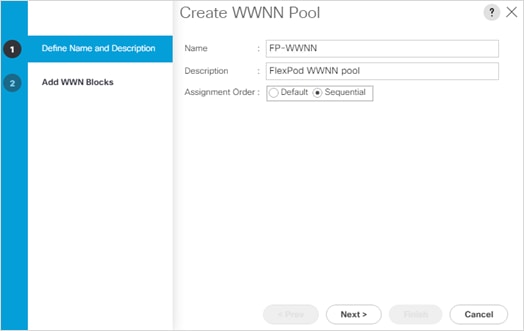
8. Click Next.
9. Click Add.
10. Modify the From field as necessary for the UCS Environment
![]() Modifications of the WWNN block, as well as the WWPN and MAC Addresses, can convey identifying information for the Cisco UCS domain. Within the From field in our example, the sixth octet was changed from 00 to FD to represent these WWNNs being in the FlexPod setup.
Modifications of the WWNN block, as well as the WWPN and MAC Addresses, can convey identifying information for the Cisco UCS domain. Within the From field in our example, the sixth octet was changed from 00 to FD to represent these WWNNs being in the FlexPod setup.
![]() When there are multiple UCS domains sitting in adjacency, it is important that these blocks; the WWNN, WWPN, and MAC, hold differing values between each set.
When there are multiple UCS domains sitting in adjacency, it is important that these blocks; the WWNN, WWPN, and MAC, hold differing values between each set.
11. Specify a size of the WWNN block sufficient to support the available server resources. In this example, with the WWNN block modification, a maximum of 128 addresses are available.
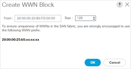
12. Click OK.
13. Click Finish and click OK to complete creating the WWNN pool.
Create WWPN Pools (FCP)
In this FlexPod implementation, WWPN address pools are created at the root organization level to avoid WWPN address pool overlaps. If your deployment plan calls for different WWPN address ranges in different UCS organizations, place the WWPN pools at the organizational level. To configure the necessary WWPN pools for the Cisco UCS environment, follow these steps:
1. In Cisco UCS Manager, click SAN.
2. Choose Pools > root.
![]() In this procedure, two WWPN pools are created, one for each switching fabric.
In this procedure, two WWPN pools are created, one for each switching fabric.
3. Right-click WWPN Pools under the root organization.
4. Choose Create WWPN Pool to create the WWPN pool.
5. Enter WWPN-Pool-A for the name of the WWPN pool.
6. Optional: Enter a description for the WWPN pool.
7. Choose Sequential for Assignment Order.
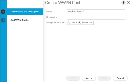
8. Click Next.
9. Click Add.
10. Specify a starting WWPN.
![]() For the FlexPod solution, the recommendation is to place AA in the next-to-last octet of the starting WWPN to identify all of the WWPNs as fabric A addresses. Merging this with the pattern we used for the WWNN we see a WWPN block starting with 20:00:00:25:B5:FD:AA:00
For the FlexPod solution, the recommendation is to place AA in the next-to-last octet of the starting WWPN to identify all of the WWPNs as fabric A addresses. Merging this with the pattern we used for the WWNN we see a WWPN block starting with 20:00:00:25:B5:FD:AA:00
11. Specify a size for the WWPN pool that is sufficient to support the available blade or server resources remembering that servers could have multiple vHBAs and unassociated service profiles could be created. In this example, with the WWPN block modification, a maximum of 128 addresses are available.
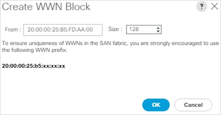
12. Click OK.
13. Click Finish.
14. In the confirmation message, click OK.
15. Right-click WWPN Pools under the root organization.
16. Choose Create WWPN Pool to create the WWPN pool.
17. Enter WWPN-Pool-B for the name of the WWPN pool.
18. Optional: Enter a description for the WWPN pool.
19. Choose Sequential for Assignment Order.
20. Click Next.
21. Click Add.
22. Specify a starting WWPN.
![]() For the FlexPod solution, the recommendation is to place B in the next-to-last octet of the starting WWPN to identify all of the WWPNs as fabric B addresses. Merging this with the pattern we used for the WWNN we see a WWPN block starting with 20:00:00:25:B5:FD:BB:00.
For the FlexPod solution, the recommendation is to place B in the next-to-last octet of the starting WWPN to identify all of the WWPNs as fabric B addresses. Merging this with the pattern we used for the WWNN we see a WWPN block starting with 20:00:00:25:B5:FD:BB:00.
23. Specify a size for the WWPN address pool that is sufficient to support the available blade or server resources remembering that servers could have multiple vHBAs and unassociated service profiles could be created. In this example, with the WWPN block modification, a maximum of 128 addresses are available.
24. Click OK.
25. Click Finish.
26. In the confirmation message, click OK.
Create VSANs (FCP)
To configure the necessary virtual storage area networks (VSANs) for the FlexPod Organization in the Cisco UCS environment, follow these steps:
1. In Cisco UCS Manager, click SAN.
![]() In this procedure, two VSANs are created, one for each SAN switching fabric.
In this procedure, two VSANs are created, one for each SAN switching fabric.
2. Choose SAN > SAN Cloud.
3. Right-click VSANs.
4. Choose Create VSAN.
5. Enter VSAN-A for the name of the VSAN to be used for Fabric A.
6. Leave FC Zoning set at Disabled.
7. Choose Fabric A.
8. Enter a unique VSAN ID and a corresponding FCoE VLAN ID that matches the configuration in the MDS switch for Fabric A. It is recommended to use the same ID for both parameters and to use something other than 1.

9. Click OK and then click OK again.
10. Under SAN Cloud, right-click VSANs.
11. Choose Create VSAN.
12. Enter VSAN-B for the name of the VSAN to be used for Fabric B.
13. Leave FC Zoning set at Disabled.
14. Choose Fabric B.
15. Enter a unique VSAN ID and a corresponding FCoE VLAN ID that matches the configuration in the MDS switch for Fabric B. It is recommended use the same ID for both parameters and to use something other than 1.
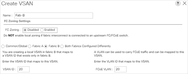
16. Click OK and then click OK again.
Create FC Uplink Port Channels (FCP)
To create the FC Uplink Port Channels and assign the appropriate VSANs to them for the Cisco UCS environment, follow these steps:
1. In Cisco UCS Manager, click SAN.
2. Choose SAN > SAN Cloud.
3. Expand Fabric A and choose FC Port Channels.
4. Right-click FC Port Channels and choose Create FC Port Channel.
5. Set a unique ID for the port channel and provide a unique name for the port channel.
6. Click Next.
7. Choose the appropriate Port Channel Admin Speed.
8. Choose the ports connected to Cisco MDS A and use >> to add them to the port channel.
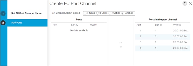
9. Click Finish to complete creating the port channel.
10. Click OK on the confirmation.
11. Under FC Port-Channels, choose the newly created port channel.
12. From the drop-down list to choose Fab-A.
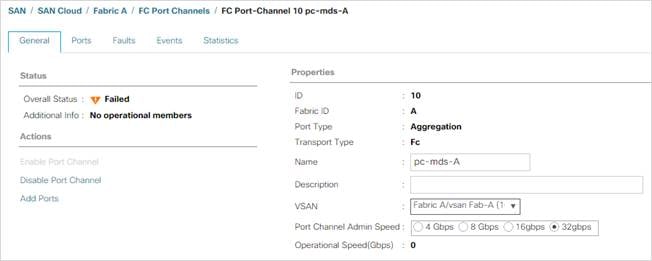
13. Click Save Changes to assign the VSAN.
14. Click OK.
![]() At this point in the deployment, since the Cisco MDS has not yet been configured, the SAN port-channel will not come up.
At this point in the deployment, since the Cisco MDS has not yet been configured, the SAN port-channel will not come up.
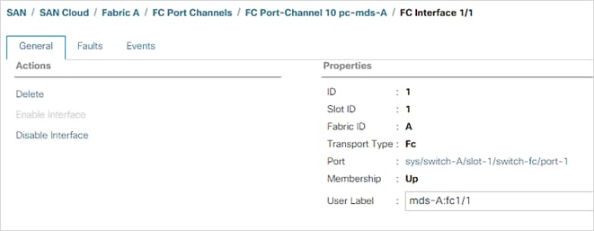
16. Expand Fabric B and choose FC Port Channels.
17. Right-click FC Port Channels and choose Create FC Port Channel.
18. Set a unique ID for the port channel and provide a unique name for the port channel.
19. Click Next.
20. Choose the ports connected to Cisco MDS B and use >> to add them to the port channel.
21. Click Finish to complete creating the port channel.
22. Click OK on the confirmation.
23. Under FC Port-Channels, choose the newly created port channel.
24. In the right pane, use the drop-down to choose Fab-B.
25. Click Save Changes to assign the VSAN.
26. Click OK.
27. Under FC Port Channels, expand FC Port-Channel 20. Under FC Port-Channel 20 choose FC Interface 1/1. Enter a User Label to indicate the connectivity on the MDS 9148T switch, such as <mds-B-hostname>:fc1/1. Click Save Changes and OK. Repeat this process for FC Interface 1/2.
Create vHBA Templates (FCP)
To create the necessary virtual host bus adapter (vHBA) templates for the Cisco UCS environment within the HANA organization, follow these steps:
1. In Cisco UCS Manager, click SAN.
2. Expand Policies > root > Sub-Organizations > HANA.
3. Right-click vHBA Templates under the HANA Organization.
4. Choose Create vHBA Template.
5. Enter vHBA-A for the vHBA template name.
6. Keep Fabric A selected.
7. Leave Redundancy Type set to No Redundancy.
8. Choose VSAN Fab-A.
9. Leave Initial Template for the Template Type.
10. Choose WWPN-Pool-A for the WWPN Pool.
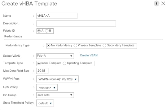
11. Click OK to create the vHBA template.
12. Click OK.
13. Right-click vHBA Templates under the HANA Organization.
14. Choose Create vHBA Template.
15. Enter vHBA-B for the vHBA template name.
16. Choose B for the Fabric ID.
17. Leave Redundancy Type set to No Redundancy.
18. Choose VSAN Fab-B.
19. Leave Initial Template for the Template Type.
20. Choose WWPN-Pool-B for the WWPN Pool.
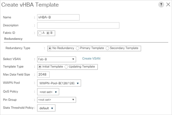
21. Click OK to create the vHBA template.
22. Click OK.
Create SAN Connectivity Policy (FCP)
To configure the necessary Infrastructure SAN Connectivity Policy within the HANA organization, follow these steps:
1. In Cisco UCS Manager, click SAN.
2. Choose SAN > Policies > root > Sub-Organizations > HANA.
3. Right-click SAN Connectivity Policies under the HANA Organization.
4. Choose Create SAN Connectivity Policy.
5. Enter FC-Boot for the name of the policy.
6. Choose the previously created WWNN-Pool for the WWNN Assignment.
7. Click Add to add a vHBA.
8. In the Create vHBA dialog box, enter vHBA-Fab-A for the name of the vHBA.
9. Choose the Use vHBA Template checkbox.
10. In the vHBA Template list, choose vHBA-A.
11. In the Adapter Policy list, choose Linux.
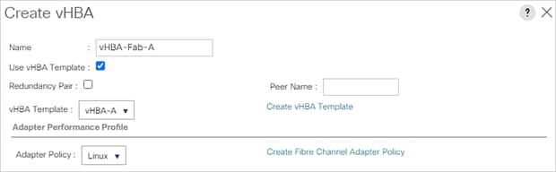
12. Click OK.
13. Click Add to add a second vHBA.
14. In the Create vHBA dialog box, enter vHBA-Fab-B for the name of the vHBA.
15. Choose the Use vHBA Template checkbox.
16. In the vHBA Template list, choose vHBA-B.
17. In the Adapter Policy list, choose Linux.
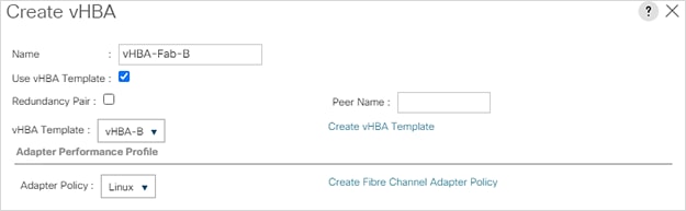
18. Click OK.
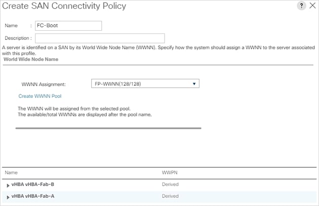
19. Click OK to create the SAN Connectivity Policy.
20. Click OK to confirm creation.
Add Block of IP Addresses for KVM Access
To create a block of IP addresses for in band server Keyboard, Video, Mouse (KVM) access in the Cisco UCS environment, follow these steps:
1. In Cisco UCS Manager, click LAN.
2. Expand Pools > root > IP Pools.
3. Right-click IP Pool ext-mgmt and choose Create Block of IPv4 Addresses.
4. Enter the starting IP address of the block, number of IP addresses required, and the subnet mask and gateway information. Optionally, enter the Primary and Secondary DNS server addresses.
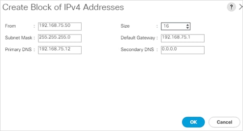
5. Click OK to create the block.
6. Click OK in the confirmation message.
Create Uplink Port Channels to Cisco Nexus Switches
To configure the necessary port channels out of the Cisco UCS environment, follow these steps:
1. In Cisco UCS Manager, click LAN.
![]() In this procedure, two port channels are created: one from fabric A to both Cisco Nexus switches and one from fabric B to both Cisco Nexus switches.
In this procedure, two port channels are created: one from fabric A to both Cisco Nexus switches and one from fabric B to both Cisco Nexus switches.
2. Under LAN > LAN Cloud, expand the Fabric A tree.
3. Right-click Port Channels under Fabric A.
4. Choose Create Port Channel.
5. Enter 41 for the unique ID of the port channel.
6. Enter Po41-Nexus for the name of the port channel.
7. Click Next.
8. Choose the uplink ports connected to the Nexus switches to be added to the port channel.
9. Click >> to add the ports to the port channel.
10. Click Finish to create the port channel.
11. Click OK.
12. In the navigation pane, under LAN > LAN Cloud > Fabric A > Port Channels, choose Port-Channel 41. Choose Auto for the Admin Speed.
13. Click Save Changes and OK. After a few minutes, verify that the Overall Status is Up, and the Operational Speed is correct.
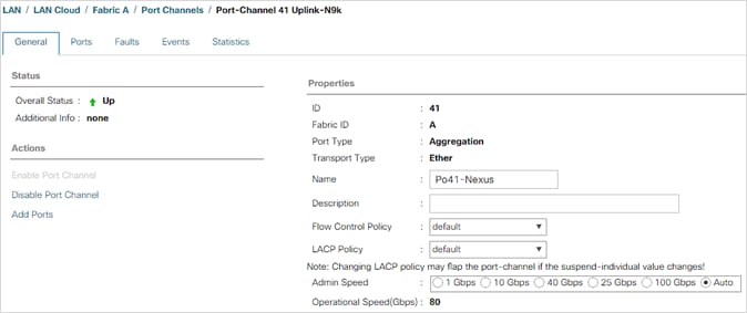
14. In the navigation pane, under LAN > LAN Cloud > Fabric A > Port Channels, expand Port-Channel 41. Under Port-Channel 41, choose Eth Interface 1/49. In the center pane under Properties, enter a User Label to indicate the port connectivity, such as <nexus-a-hostname>:Eth1/33 Click Save Changes and click OK. Repeat steps 1-14 for the remaining uplink ports.
15. In the navigation pane, under LAN > LAN Cloud, expand the Fabric B tree.
16. Right-click Port Channels under Fabric B.
17. Choose Create Port Channel.
18. Enter 42 for the unique ID of the port channel.
19. Enter Po42-Nexus for the name of the port channel.
20. Click Next.
21. Choose the ports connected to the Nexus switches to be added to the port channel:
22. Click >> to add the ports to the port channel.
23. Click Finish to create the port channel.
24. Click OK.
25. In the navigation pane, under LAN > LAN Cloud > Fabric B > Port Channels, choose Port-Channel 42. Choose Auto Gbps for the Admin Speed.
26. Click Save Changes and OK. After a few minutes, verify that the Overall Status is Up, and the Operational Speed is correct.
27. In the navigation pane, under LAN > LAN Cloud > Fabric A > Port Channels, expand Port-Channel 42. Under Port-Channel 42, choose Eth Interface 1/49. In the center pane under Properties, enter a User Label to indicate the port connectivity, such as <nexus-b-hostname>:Eth1/33 Click Save Changes and click OK. Repeat steps 1-27 for the remaining uplink ports.
Set Jumbo Frames in Cisco UCS Fabric
Jumbo Frames are used in FlexPod for the NFS storage protocols. The normal best practice in FlexPod has been to set the MTU of the Best Effort QoS System Class in Cisco UCS Manager to 9216 for Jumbo Frames. In the Cisco UCS 6454 Fabric Interconnect with UCS Manager version 4.0 software the MTU for the Best Effort QoS System Class is fixed at normal and cannot be changed. With this setting of normal in the 6454, Jumbo Frames can pass through the Cisco UCS fabric without being dropped. In UCS Manager version 4.1, the MTU for the Best Effort QoS System Class is again settable. To configure jumbo frames in the UCS fabric, follow these steps:
1. In Cisco UCS Manager, click LAN.
2. Expand LAN > LAN Cloud > QoS System Class.
3. In the right pane, click the General tab.
4. On the Best Effort row, enter 9216 in the box under the MTU column.
5. Click Save Changes.
6. Click OK.
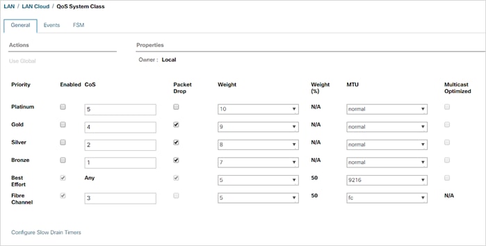
![]() Only the Fibre Channel and Best Effort QoS System Classes are enabled in this FlexPod implementation. The Cisco UCS and Cisco Nexus switches are intentionally configured this way so that all IP traffic within the FlexPod will be treated as Best Effort. Enabling the other QoS System Classes without having a comprehensive, end-to-end QoS setup in place can cause difficult to troubleshoot issues. For example, NetApp storage controllers by default mark IP-based, VLAN-tagged packets with a CoS value of 4. With the default configuration on the Cisco Nexus switches in this implementation, storage packets will pass through the switches and into the Cisco UCS Fabric Interconnects with CoS 4 set in the packet header. If the Gold QoS System Class in the Cisco UCS is enabled and the corresponding CoS value left at 4, these storage packets will be treated according to that class and if Jumbo Frames is being used for the storage protocols, but the MTU of the Gold QoS System Class is not set to Jumbo (9216), packet drops will occur. Note also that if the Platinum class is enabled, the MTU must be set to 9216 to use Jumbo Frames in that class.
Only the Fibre Channel and Best Effort QoS System Classes are enabled in this FlexPod implementation. The Cisco UCS and Cisco Nexus switches are intentionally configured this way so that all IP traffic within the FlexPod will be treated as Best Effort. Enabling the other QoS System Classes without having a comprehensive, end-to-end QoS setup in place can cause difficult to troubleshoot issues. For example, NetApp storage controllers by default mark IP-based, VLAN-tagged packets with a CoS value of 4. With the default configuration on the Cisco Nexus switches in this implementation, storage packets will pass through the switches and into the Cisco UCS Fabric Interconnects with CoS 4 set in the packet header. If the Gold QoS System Class in the Cisco UCS is enabled and the corresponding CoS value left at 4, these storage packets will be treated according to that class and if Jumbo Frames is being used for the storage protocols, but the MTU of the Gold QoS System Class is not set to Jumbo (9216), packet drops will occur. Note also that if the Platinum class is enabled, the MTU must be set to 9216 to use Jumbo Frames in that class.
Within Cisco UCS, all the network types for an SAP HANA system are manifested by defined VLANs. Network design guideline from SAP recommends seven SAP HANA related networks and two infrastructure related networks.
Even though nine VLANs are defined, VLANs for all the networks are not necessary if the solution will not use those networks. For example, if the Replication Network is not used in the solution, then VLAN ID 225 need not be created.
The VLAN IDs can be changed if required to match the VLAN IDs in the customer’s network – for example, ID 222 for backup should match the configured VLAN ID at the customer uplink network switches.
To configure the necessary VLANs for the Cisco UCS environment, follow these steps:
![]() For this deployment we created eight VLANs. Depending on the customer requirements and the SAP HANA scenario, the total number of VLANs might differ in a different environment.
For this deployment we created eight VLANs. Depending on the customer requirements and the SAP HANA scenario, the total number of VLANs might differ in a different environment.
1. In Cisco UCS Manager, click LAN.
2. Expand LAN > LAN Cloud.
3. Right-click VLANs and select Create VLANs.
4. Enter HANA-Mgmt for the name of the VLAN to be used as HANA node management network.
5. Keep the Common/Global option selected for the scope of the VLAN.
6. Enter <var_mgmt_vlan_id> for the ID of the HANA Node-to-Node network.
7. Keep the Sharing Type as None.
8. Click OK and then click OK again.
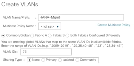
9. Create VLAN HANA-AppServer using <var_appserver_vlan_id>
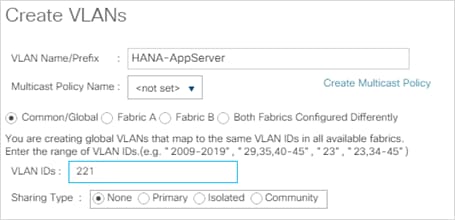
10. Create VLAN HANA-Backup using <var_backup_vlan_id>
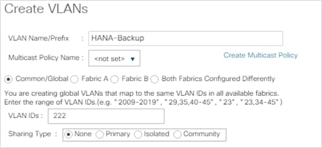
11. Create VLAN HANA-Client using <var_client_vlan_id>.
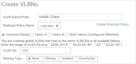
12. Create VLAN HANA-DataSource using <var_datasource_vlan_id>.
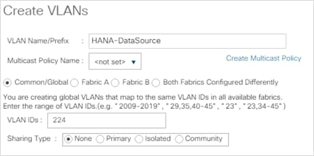
13. Create VLAN HANA-Internal Node-to-Node traffic using <var_internal_vlan_id>.
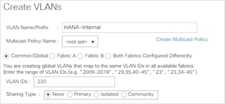
14. Create VLAN HANA-Replication using <var_replication_vlan_id>.
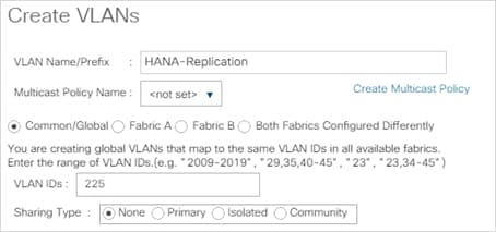
15. Create VLAN HANA-sharednfs for /hana/shared NFS network.
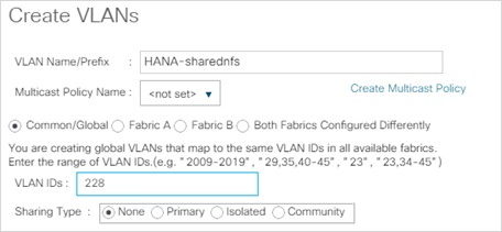
![]() Modify these VLAN names as necessary for your environment.
Modify these VLAN names as necessary for your environment.
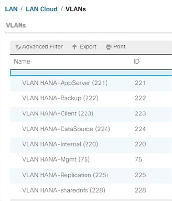
![]() With two ports in use for the uplink port channel to the Cisco Nexus Switches providing 50GbE per fabric serving the critical HANA-internal and HANA-sharednfs networks along with other HANA system networks, this validation allows traffic of all VLANs flow on all uplink ports.
With two ports in use for the uplink port channel to the Cisco Nexus Switches providing 50GbE per fabric serving the critical HANA-internal and HANA-sharednfs networks along with other HANA system networks, this validation allows traffic of all VLANs flow on all uplink ports.
![]() Depending on the customer requirements and implementation scenario you may want to simplify management and bandwidth allocation based on separate designated uplink port channels using VLAN groups.
Depending on the customer requirements and implementation scenario you may want to simplify management and bandwidth allocation based on separate designated uplink port channels using VLAN groups.
In this FlexPod deployment, MAC address pools are created at the root organization level to avoid MAC address pool overlaps. If your deployment plan calls for different MAC address ranges in different UCS organizations, place the MAC pools at the organizational level. To configure the necessary MAC address pools for the Cisco UCS environment, follow these steps:
1. In Cisco UCS Manager, click LAN.
2. Expand Pools > root.
![]() In this procedure, two MAC address pools are created, one for each switching fabric.
In this procedure, two MAC address pools are created, one for each switching fabric.
3. Right-click MAC Pools under the root organization.
4. Choose Create MAC Pool to create the MAC address pool.
5. Enter MAC-Pool-A for the name of the MAC pool.
6. Optional: Enter a description for the MAC pool.
7. Choose Sequential for the Assignment Order.
8. Click Next.
9. Click Add.
10. Specify a starting MAC address.
![]() For the FlexPod solution, the recommendation is to place AA in the next-to-last octet of the starting MAC address to identify all of the MAC addresses as fabric A addresses. In our example, we have carried forward the example of also embedding the Platform information giving us 00:25:B5:FD:AA:00 as our first MAC address.
For the FlexPod solution, the recommendation is to place AA in the next-to-last octet of the starting MAC address to identify all of the MAC addresses as fabric A addresses. In our example, we have carried forward the example of also embedding the Platform information giving us 00:25:B5:FD:AA:00 as our first MAC address.
11. Specify a size for the MAC address pool that is sufficient to support the available blade or server resources remembering that a server may contain multiple vNICs and that multiple unassociated Service Profiles can be created. In this example, with the MAC block modification, a maximum of 256 addresses are available.
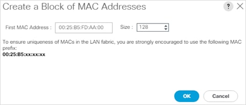
12. Click OK.
13. Click Finish.
14. In the confirmation message, click OK.
15. Right-click MAC Pools under the root organization.
16. Choose Create MAC Pool to create the MAC address pool.
17. Enter MAC-Pool-B for the name of the MAC pool.
18. Optional: Enter a description for the MAC pool.
19. Choose Sequential for the Assignment Order.
20. Click Next.
21. Click Add.
22. Specify a starting MAC address.
![]() For the FlexPod solution, it is recommended to place BB in the next to last octet of the starting MAC address to identify all the MAC addresses in this pool as fabric B addresses. Once again, we have carried forward our example of also embedding platform information giving us 00:25:B5:FD:BB:00 as our first MAC address.
For the FlexPod solution, it is recommended to place BB in the next to last octet of the starting MAC address to identify all the MAC addresses in this pool as fabric B addresses. Once again, we have carried forward our example of also embedding platform information giving us 00:25:B5:FD:BB:00 as our first MAC address.
23. Specify a size for the MAC address pool that is sufficient to support the available blade or server resources remembering that a server may contain multiple vNICs and that multiple unassociated Service Profiles can be created.
24. Click OK.
25. Click Finish.
26. In the confirmation message, click OK.
Create Network Control Policy for Cisco Discovery Protocol (CDP) and Link Layer Discovery Protocol (LLDP)
To create a network control policy that enables CDP and LLDP on the server virtual network controller (vNIC) ports, follow these steps:
1. In Cisco UCS Manager, click LAN.
2. Expand Policies > root.
3. Right-click Network Control Policies.
4. Choose Create Network Control Policy.
5. Enter Enable-CDP-LLDP for the policy name.
6. For CDP, choose the Enabled option.
7. For LLDP, scroll down and choose Enabled for both Transmit and Receive.
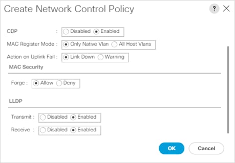
8. Click OK to create the network control policy.
9. Click OK.
Each VLAN is mapped to a vNIC template to specify the characteristic of a specific network To create multiple virtual network interface card (vNIC) templates within the HANA organization, follow these steps.
1. In Cisco UCS Manager, click LAN.
2. Expand Policies > root > Sub-Organizations > HANA
3. Under the HANA Organization, right-click vNIC Templates.
4. Choose Create vNIC Template.
5. Enter HANA-Internal for the vNIC template name.
6. Keep Fabric A selected (alter to Fabric B for the next vNIC Template).
7. Check the Enable Failover checkbox.
8. Leave the Peer Redundancy Template set to <not set>.
9. Under Target, make sure that only the Adapter checkbox is selected.
10. Choose Updating Template for the Template Type.
11. Under VLANs, choose the checkboxes for HANA-Internal VLAN.
12. Enable the native VLAN radio button for the VLAN HANA-Internal VLAN.
13. Choose vNIC Name for the CDN Source.
14. For MTU, enter 9000.
15. In the MAC Pool list, choose MAC-Pool-A (Select FI-B for the next vNIC Template).
16. In the Network Control Policy list, choose Enable-CDP-LLDP.
17. Click OK.
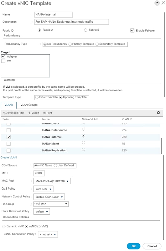
18. Continue to create a vNIC template for each VLAN altering the FI-A and FI-B assignments to distribute the traffic between the Fabrics.
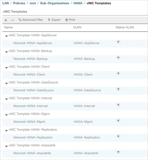
Create vNIC/vHBA Placement Policy
Cisco UCS assigns virtual network interface connections (vCons) to the PCIe adapter cards in the server. Each vCon is a virtual representation of a physical adapter that can be assigned vNICs and vHBAs.
For blade or rack servers that contain one adapter, Cisco UCS assigns all vCons to that adapter.
For blade or rack servers that contain two or three adapters, Cisco UCS assigns the vCons based on the selected virtual slot mapping scheme. This can be one of the following:
● Round Robin— In a server with two adapter cards, Cisco UCS assigns vCon1 and vCon3 to Adapter1, then assigns vCon2 and vCon4 to Adapter2. In a server with three adapter cards, Cisco UCS assigns vCon1 to Adapter1, vCon2 and vCon4 to Adapter2, and vCon3 to Adapter3. This is the default scheme.
● Linear Ordered— In a server with two adapter cards, Cisco UCS assigns vCon1 and vCon2 to Adapter1, then assigns vCon3 and vCon4 to Adapter2.In a server with three adapter cards, Cisco UCS assigns vCon1 to Adapter1 and vCon2 to Adapter2, then assigns vCon3 and vCon4 to Adapter3.
To create a vNIC/vHBA placement policy for the SAP HANA hosts, follow these steps:
1. Find the installed adapters in the system:
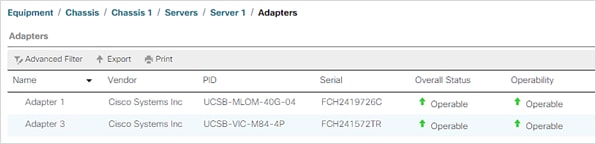
2. Choose a virtual slot mapping scheme and create a placement policy.
3. In Cisco UCS Manager, click the Servers tab in the navigation pane.
4. Select Policies > root > Sub-Organization > HANA.
5. Right-click vNIC/vHBA Placement Policies.
6. Select Create Placement Policy.
7. Enter HANA for the name of the placement policy and select Liner Ordered for Virtual Slot Mapping Scheme.
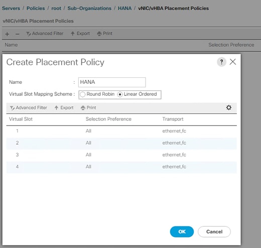
For the Placement policy, considering the installed adapters helps to be sure of what vCONs to use for vNIC assignment.
![]() In the validation setup, we used the Cisco UCS B480 M5 server configured with Cisco UCS VIC1440 and Cisco UCS VIC1480. These appear as Adpater1 and Adapter 3. The linear ordered virtual slot mapping scheme-based placement policy with two adapters suggests that we should be using the vCONs 1 and 3 for vNIC assignment.
In the validation setup, we used the Cisco UCS B480 M5 server configured with Cisco UCS VIC1440 and Cisco UCS VIC1480. These appear as Adpater1 and Adapter 3. The linear ordered virtual slot mapping scheme-based placement policy with two adapters suggests that we should be using the vCONs 1 and 3 for vNIC assignment.
Create LAN Connectivity Policy
With LAN connectivity policy, you need to define the vNICs that a system needs to have in order to cater to the specific networks the use-case demands.
For both SAP HANA scale-up and scale-out system use cases, apart from the admin/management the node may need backup and application server network connections, at a minimum. It could have other networks depending on usage.
However, for the scale-out system scenario, inter-node communication is mandatory and that is what distinguishes it from a single host system’s policy.
In the following steps, you will create separate LAN connectivity policies for the two-standard use cases. This further simplifies the service profile template creation by having the pre-determined vNICs already part of the network configuration.
SAP HANA Scale-Up System Use Case
To configure the necessary LAN Connectivity Policy within the HANA Organization, follow these steps:
1. In Cisco UCS Manager, click LAN.
2. Expand LAN > Policies > root > Sub-Organizations > HANA.
3. Right-click LAN Connectivity Policies.
4. Select Create LAN Connectivity Policy.
5. Enter scale-up for the name of the policy.
6. Click Add to add a vNIC.
7. In the Create vNIC dialog box, enter Mgmt for the name of the vNIC.
8. Select the Use vNIC Template checkbox.
9. In the vNIC Template list, select HANA-Mgmt.
10. In the Adapter Policy list, select Linux.
11. Click OK to add this vNIC to the policy.
12. Click Add to add another vNIC to the policy.
13. In the Create vNIC box, enter appserver for the name of the vNIC.
14. Select the Use vNIC Template checkbox.
15. In the vNIC Template list, select HANA-AppServer.
16. In the Adapter Policy list, select Linux.
17. Click OK to add the vNIC to the policy.
18. Click Add to add another vNIC to the policy.
19. In the Create vNIC dialog box, enter backup for the name of the vNIC.
20. Select the Use vNIC Template checkbox.
21. In the vNIC Template list, select HANA-Backup.
22. In the Adapter Policy list, select Linux.
23. Click OK to add this vNIC to the policy.
24. Click Add to add another vNIC to the policy.
25. In the Create vNIC dialog box, enter sharednfs for the name of the vNIC.
26. Select the Use vNIC Template checkbox.
27. In the vNIC Template list, select HANA-sharednfs.
28. In the Adapter Policy list, select Linux.
29. Click OK to add this vNIC to the policy.
30. Click Add to add a vNIC.
31. In the Create vNIC dialog box, enter sysrep for the name of the vNIC.
32. Select the Use vNIC Template checkbox.
33. In the vNIC Template list, select HANA-Replication.
34. In the Adapter Policy list, select Linux.
35. Click OK to add this vNIC to the policy.
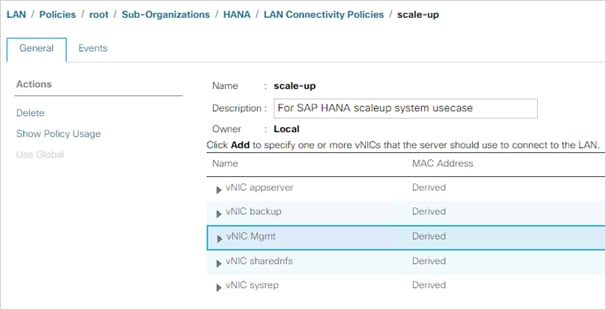
SAP HANA Scale-Out System Use Case
To configure the necessary LAN Connectivity Policy within the T01-HANA Organization, follow these steps:
1. In Cisco UCS Manager, click LAN.
2. Expand LAN > Policies > root > Sub-Organizations > HANA Organization.
3. Right-click LAN Connectivity Policies.
4. Select Create LAN Connectivity Policy.
5. Enter scale-out for the name of the policy.
6. Click Add to add a vNIC.
7. In the Create vNIC dialog box, enter Mgmt for the name of the vNIC.
8. Check the Use vNIC Template checkbox.
9. In the vNIC Template list, select HANA-Mgmt.
10. In the Adapter Policy list, select Linux.
11. Click OK to add this vNIC to the policy.
12. Click Add to add another vNIC to the policy.
13. In the Create vNIC box, enter internode for the name of the vNIC.
14. Check the Use vNIC Template checkbox.
15. In the vNIC Template list, select HANA-Internal.
16. In the Adapter Policy list, select HANA.
17. Click OK to add the vNIC to the policy.
18. Click Add to add a vNIC.
19. In the Create vNIC dialog box, enter appserver for the name of the vNIC.
20. Check the Use vNIC Template checkbox.
21. In the vNIC Template list, select HANA_AppServer.
22. In the Adapter Policy list, select Linux.
23. Click OK to add this vNIC to the policy.
24. Click Add to add a vNIC.
25. In the Create vNIC dialog box, enter sharednfs for the name of the vNIC.
26. Check the Use vNIC Template checkbox.
27. In the vNIC Template list, select HANA-sharednfs.
28. In the Adapter Policy list, select HANA.
29. Click OK to add this vNIC to the policy.
30. Click Add to add a vNIC.
31. In the Create vNIC dialog box, enter backup for the name of the vNIC.
32. Check the Use vNIC Template checkbox.
33. In the vNIC Template list, select HANA-Backup.
34. In the Adapter Policy list, select Linux.
35. Click OK to add this vNIC to the policy.
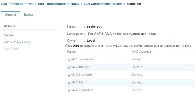
To configure the necessary universally unique identifier (UUID) suffix pool for the Cisco UCS environment, follow these steps:
1. In Cisco UCS Manager, click Servers.
2. Expand Pools > root.
3. Right-click UUID Suffix Pools.
4. Choose Create UUID Suffix Pool.
5. Enter UUID-Pool for the name of the UUID suffix pool.
6. Optional: Enter a description for the UUID suffix pool.
7. Keep the prefix at the derived option.
8. Choose Sequential for the Assignment Order.
9. Click Next.
10. Click Add to add a block of UUIDs.
11. Keep the From field at the default setting.
12. Specify a size for the UUID block that is sufficient to support the available blade or server resources and the number of Service Profiles that will be created.
13. Click OK.
14. Click Finish.
15. Click OK.
Modify Default Host Firmware Package
Firmware management policies allow the administrator to choose the corresponding packages for a given server configuration. These policies often include packages for adapter, BIOS, board controller, FC adapters, host bus adapter (HBA) option ROM, and storage controller properties.
To modify the default firmware management policy in the Cisco UCS environment, follow these steps:
1. In Cisco UCS Manager, click Servers.
2. Expand Policies > root.
3. Expand Host Firmware Packages.
4. Choose default.
5. In the Actions pane, choose Modify Package Versions.
6. Choose version 4.1(1d) for both the Blade and Rack Packages.
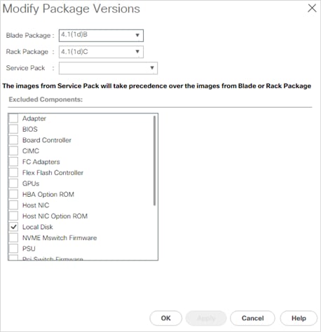
7. Click OK, then click OK again to modify the host firmware package.
Create Local Disk Configuration Policy (Optional)
A local disk configuration specifying no local disks for the Cisco UCS environment can be used to ensure that servers with no local disks are used for SAN Boot. local disks.
To create a local disk configuration policy, follow these steps:
1. In Cisco UCS Manager, click Servers.
2. Expand Policies > root.
3. Right-click Local Disk Config Policies.
4. Choose Create Local Disk Configuration Policy.
5. Enter SAN-Boot for the local disk configuration policy name.
6. Change the mode to No Local Storage.
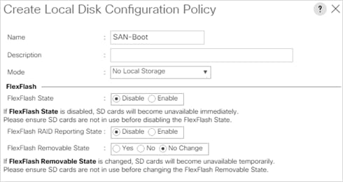
7. Click OK to create the local disk configuration policy.
8. Click OK.
To create a power control policy for the Cisco UCS environment, follow these steps:
1. In Cisco UCS Manager, click Servers.
2. Expand Policies > root.
3. Right-click Power Control Policies.
4. Choose Create Power Control Policy.
5. Enter No-Power-Cap for the power control policy name.
6. Change the power capping setting to No Cap.
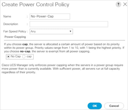
7. Click OK to create the power control policy.
8. Click OK.
Update the Default Maintenance Policy
To update the default Maintenance Policy to either require user acknowledgement before server boot when service profiles change or to make the changes on the next server reboot, follow these steps:
1. In Cisco UCS Manager, click Servers.
2. Expand Policies > root.
3. Choose Maintenance Policies > default.
4. Change the Reboot Policy to User Ack.
5. Choose “On Next Boot” to delegate maintenance windows to server administrators.
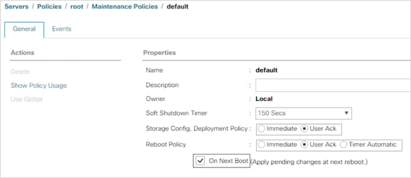
6. Click Save Changes.
7. Click OK to accept the changes.
Best performance of the SAP HANA environment requires to configure the Server BIOS accurately. Create a server BIOS policy for the Cisco UCS environment:
1. In Cisco UCS Manager, click the Servers tab in the navigation pane.
2. Select Policies > root > Sub-Organization > HANA > BIOS Policies.
3. Right-click BIOS Policies and select Create BIOS Policy.
4. Enter HANA-BIOS as BIOS policy name.
5. Select Reboot on BIOS Settings Change.
6. Click OK and confirm the new BIOS Policy with OK.
7. Select the HANA-BIOS policy in the navigation pane.
8. On the Main sub tab, change the Quiet Boot setting from Platform Default to Disabled.
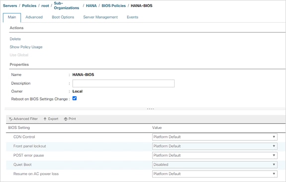
9. Click the Advanced tab.
10. Click the Processor tab and change CPU Performance from Platform Default to Enterprise:
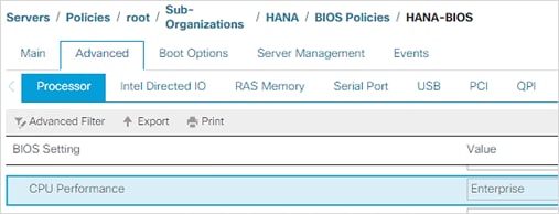
a. Keep processor C State on platform default.
b. Keep Processor C1E on Platform Default.
c. Change Processor C3, C6 and C7 Report to disabled.
d. Change Power Technology from Platform Default to Performance.
e. Change Energy Performance from Platform Default to Performance.
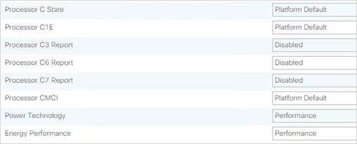
11. In the RAS Memory tab change the LV DDR Mode to performance mode and enable NUMA. Keep the memory RAS configuration on platform default.
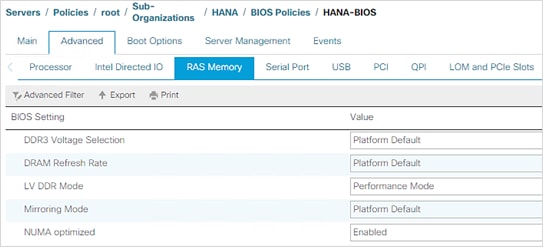
12. Enable Serial Port A in the Serial Port tab.
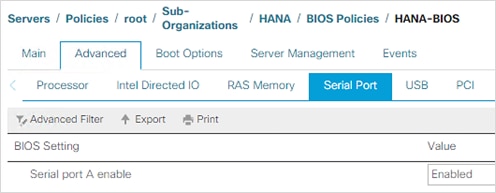
13. In the Server Management tab, configure the Console Redirection to serial-port-a with the BAUD Rate 115200 and enable the feature Legacy OS redirect. This is used for Serial Console Access over LAN to all SAP HANA servers.
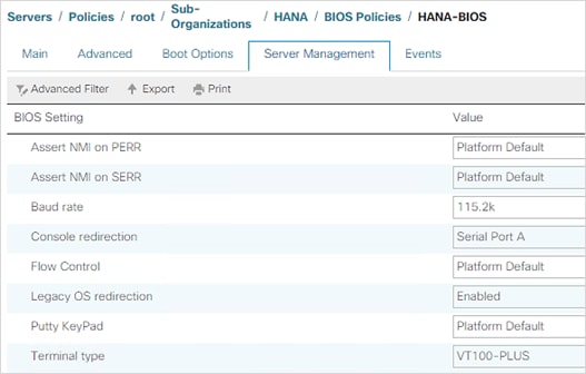
14. Click Save Changes to update the BIOS Policy.
15. Click OK.
Create FC Boot Policy (FCP)
This procedure applies to a Cisco UCS environment in which at least two Fibre Channel logical interfaces (LIFs) are on cluster node 1 (fcp-1a and fcp-1b) and two Fibre Channel LIFs are on cluster node 2 (fcp-2a and fcp-2b). Also, it is assumed that the A LIFs are connected to Fabric A (Cisco UCS Fabric Interconnect A) and the B LIFs are connected to Fabric B (Cisco UCS Fabric Interconnect B).
To create the FC boot policy, follow these steps:
1. Make sure the NetApp array for the LIFs is configured for infra SVM:
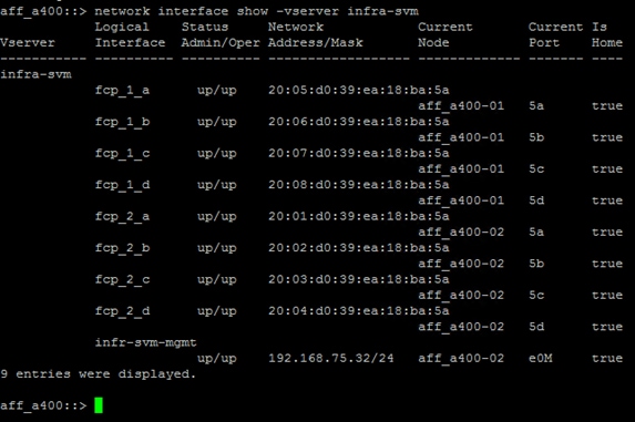
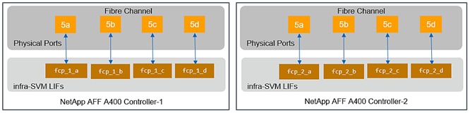
2. Make a note of the FC ports and their physical WWPN IDs from the ONTAP system manager Network > FC Ports page, as shown below:
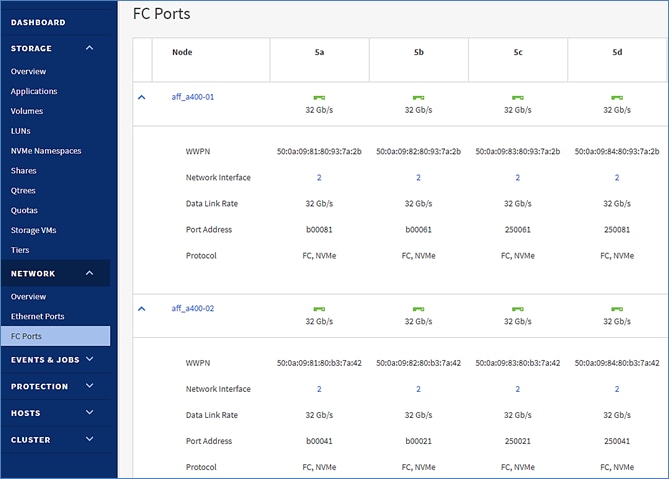
3. Log into MDS A and B and verify the fabric logins:
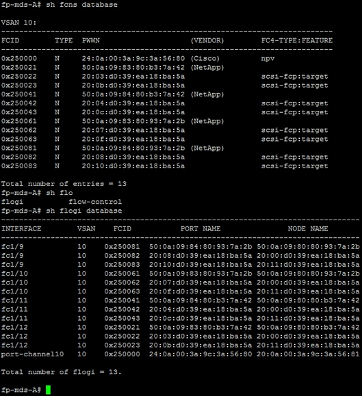
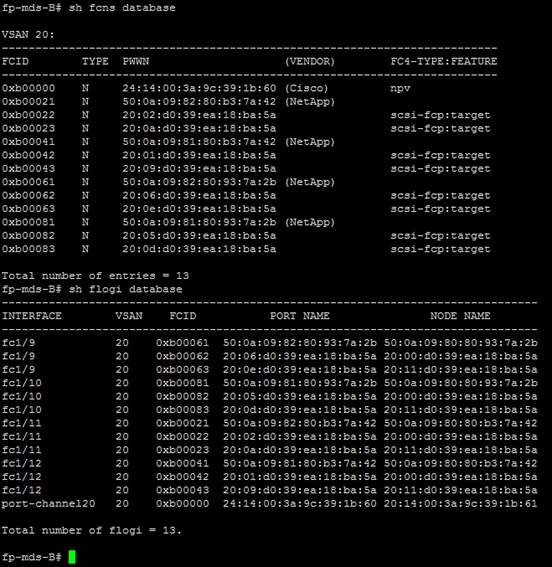
![]() For each fabric login from the NetApp array, the WWPN starting at 50 corresponds to the WWPN of the physical port. The WWPNs that start at 20 correspond to LIFs WWPN configured one each for infra and HANA SVMs.
For each fabric login from the NetApp array, the WWPN starting at 50 corresponds to the WWPN of the physical port. The WWPNs that start at 20 correspond to LIFs WWPN configured one each for infra and HANA SVMs.
4. Based on the port mappings, make a reference connection diagram for easy visualization as shown below:
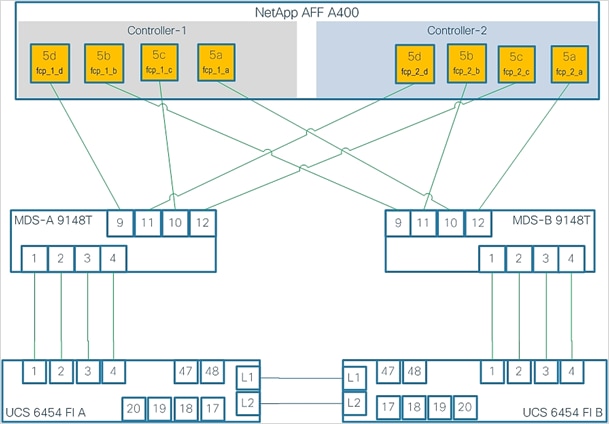
We chose the WWPNs corresponding to infra SVM for the boot policy as targets. In this example, we used LIFs fcp_1_c and fcp_2_c, such as 20:07:d0:39:ea:18:ba:5a and 20:03:d0:39:ea:18:ba:5a for SAN Primary and Secondary targets. LIFs fcp_2_a and fcp_1_a, such as 20:01:d0:39:ea:18:ba:5a and 20:05:d0:39:ea:18:ba:5a are used as SAN Secondary’s primary and secondary targets.
![]() ONTAP command network fcp topology show displays the details of the MDS; what each FC port is connected to and the created LIFs, as well as the physical ports’ WWPN information.
ONTAP command network fcp topology show displays the details of the MDS; what each FC port is connected to and the created LIFs, as well as the physical ports’ WWPN information.
To create a boot policy for the within the HANA organization, follow these steps:
1. In Cisco UCS Manager, click Servers.
2. Expand Policies > root > Sub-Organizations > HANA.
3. Under the HANA Organization, right-click Boot Policies.
4. Choose Create Boot Policy.
5. Enter Boot-FCP for the name of the boot policy.
6. Optional: Enter a description for the boot policy.
7. Do not select the Reboot on Boot Order Change checkbox.
8. Choose the Uefi Boot Mode.
9. Do not choose the Boot Security checkbox.
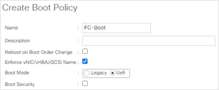
10. Expand Local Devices and choose Add Remote CD/DVD.
11. Expand vHBAs and choose Add SAN Boot.
12. Choose Primary for the type field.
13. Enter vHBA-Fab-A in the vHBA field.
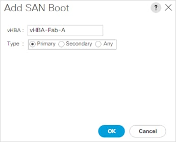
14. Click OK.
15. From vHBAs, choose Add SAN Boot Target.
16. Keep 0 for the value for Boot Target LUN.
17. Enter the WWPN for LIF fcp_1_c.
![]() To obtain this information, log into the storage cluster and run the network interface show -vserver infra-svm command.
To obtain this information, log into the storage cluster and run the network interface show -vserver infra-svm command.
18. Choose Primary for the SAN boot target type.
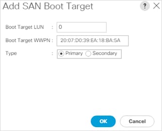
19. Click OK to add the SAN boot target.
20. From vHBAs, choose Add SAN Boot Target.
21. Enter 0 for the value for Boot Target LUN.
22. Enter the WWPN for LIF fcp_2_c.
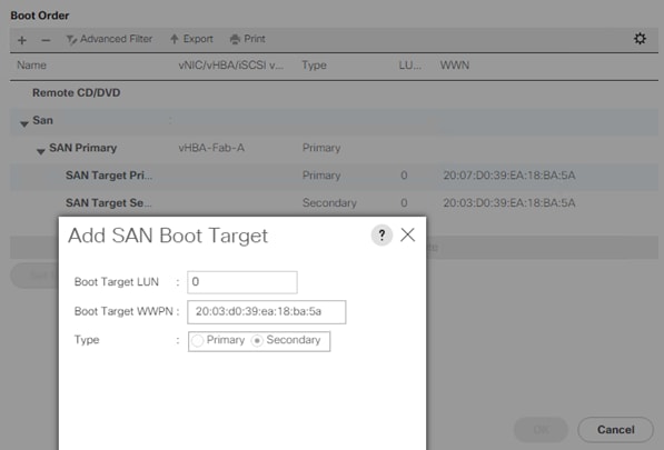
23. Click OK to add the SAN boot target.
24. Add SAN Secondary. Add its primary and secondary targets. We chose controllers fcp_1_a and fcp_2_a for this deployment.
25. From vHBAs, choose Add SAN Boot.
26. In the Add SAN Boot dialog box, enter FCP-Fabric-B in the vHBA box.
27. The SAN boot type should automatically be set to Secondary.
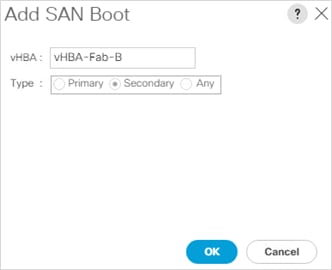
28. Click OK.
29. From vHBAs, choose Add SAN Boot Target.
30. Keep 0 for the value for Boot Target LUN.
31. Enter the WWPN for LIF fcp_2_a.
32. Choose Primary for the SAN boot target type.
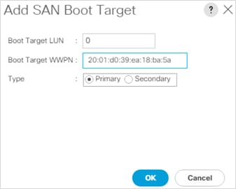
33. Click OK to add the SAN boot target.
34. From vHBAs, choose Add SAN Boot Target.
35. Keep 0 for the value for Boot Target LUN.
36. Enter the WWPN for LIF fcp_1_a.
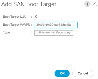
37. Click OK to add the SAN boot target.
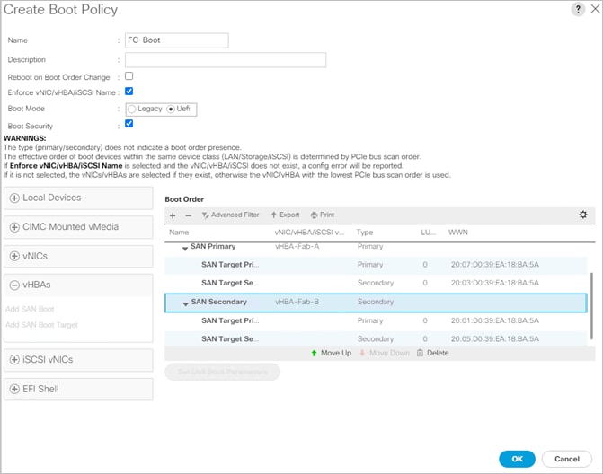
38. Click OK, then click OK again to create the boot policy.
Create Service Profile Template (FCP)
In this procedure, one service profile template for HANA nodes is created with FC boot within the HANA organization. The steps to create service profile template to instantiate HANA nodes for SAP HANA scale-up or scale-out use case depends on the LAN connectivity policy you select and corresponding placement of vNICs per vCONs.
To create the service profile template, follow these steps:
1. In Cisco UCS Manager, click Servers.
2. Expand Service Profile Templates > root > Sub-Organizations > HANA.
3. Right-click the HANA Organization.
4. Choose Create Service Profile Template to open the Create Service Profile Template wizard.
5. Enter HANA-node for the name of the service profile template.
6. Choose the Updating Template option.
7. Under UUID, choose UUID-Pool for the UUID pool.
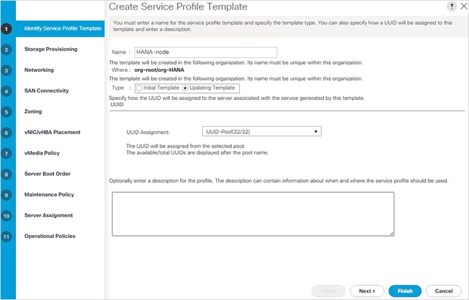
8. Click Next.
Configure Storage Provisioning
To configure storage provisioning, follow these steps:
1. If you have servers with no physical disks, click the Local Disk Configuration Policy tab and choose the SAN-Boot Local Storage Policy. Otherwise, choose the default Local Storage Policy.
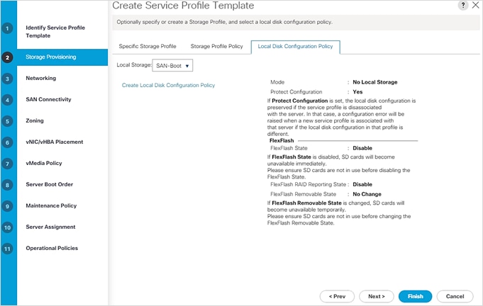
2. Click Next.
To configure the network options for HANA node intended to be scale-up system, follow these steps:
1. Keep the default setting for Dynamic vNIC Connection Policy.
2. Choose the “Use Connectivity Policy” option to configure the LAN connectivity.
3. Choose ‘scale-up’ from the LAN Connectivity Policy drop-down list.
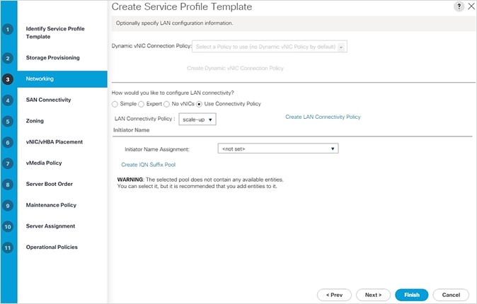
4. Click Next.
OR
To configure the network options for the HANA node that is intended to be part of the scale-out cluster, follow these steps:
1. Keep the default setting for Dynamic vNIC Connection Policy.
2. Select the “Use Connectivity Policy” option to configure the LAN connectivity.
3. Select scale-out from the LAN Connectivity Policy drop-down list.

4. Click Next.
To configure SAN connectivity, follow these steps:
1. Choose the Use Connectivity Policy option for the “How would you like to configure SAN connectivity?” field.
2. Choose the FC-Boot option from the SAN Connectivity Policy drop-down list.
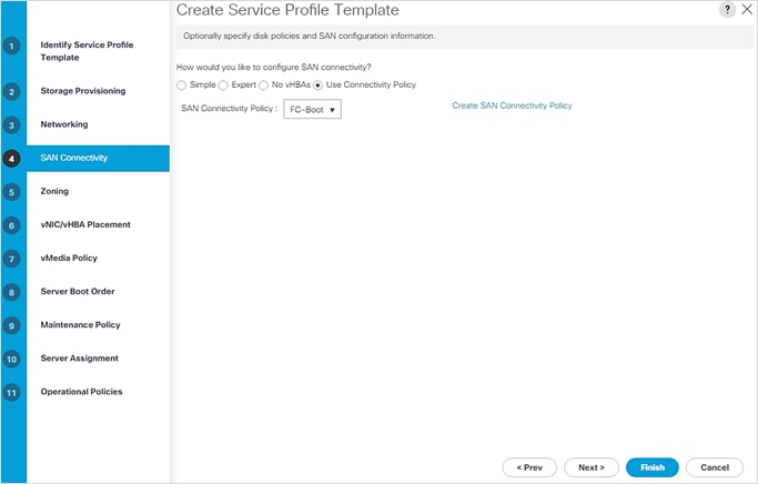
3. Click Next.
To configure zoning, follow this step:
1. Set no zoning options and click Next.
To configure the vNIC/vHBA placement in case of Scale-up system, follow these steps:
1. In the “Select Placement” list, Select HANA.
2. Manually assign the vNICs to vCon1 and vCon3 as below:
![]() Although five networks were defined, they are optional and if they are not required in your deployment, the addition of a vNIC template for that network may be omitted.
Although five networks were defined, they are optional and if they are not required in your deployment, the addition of a vNIC template for that network may be omitted.
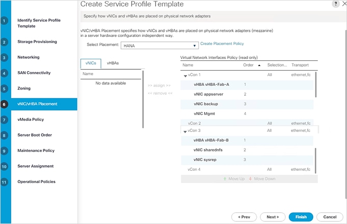
3. Click Next.
To configure the vNIC/HBA placement for a scale-out system, follow these steps:
1. In the “Select Placement” list, choose HANA.
2. Manually assign the vNICs to vCon1 and vCon3 as below:
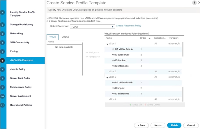
3. Click Next.
![]() Although five networks were defined, they are optional and if they are not needed in your deployment, the addition of a vNIC template for that network may be omitted.
Although five networks were defined, they are optional and if they are not needed in your deployment, the addition of a vNIC template for that network may be omitted.
To configure the vMedia policy, follow these steps:
1. Do not select a vMedia Policy.
2. Click Next.
To configure the server boot order, follow these steps:
1. Choose FC-Boot for Boot Policy.
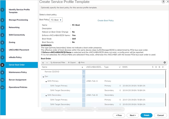
2. Click Next.
To configure the maintenance policy, follow these steps:
1. Change the Maintenance Policy to default.
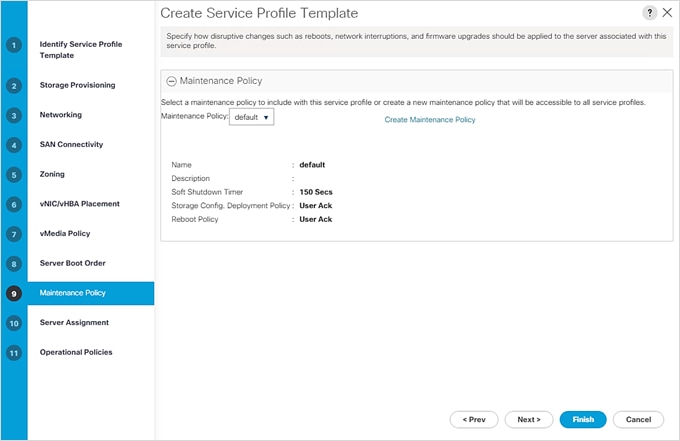
2. Click Next.
To configure the server assignment, follow this step:
1. Select defaults with Server assignment and Firmware Management. Click Next.
Configure Operational Policies
To configure the operational policies, follow these steps:
1. In the BIOS Policy list, choose HANA-BIOS.
2. Expand Management IP Address. For Outband IPV4 select ext-mgmt from the drop-down list.
3. Expand Power Control Policy Configuration and choose No-Power-Cap in the Power Control Policy list.
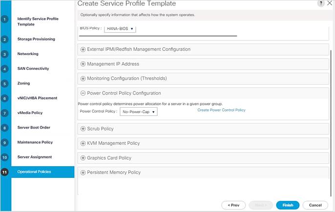
4. Click Finish to create the service profile template.
5. Click OK in the confirmation message.
Depending on the LAN connectivity policy you configured while creating the Service Profile Template, to create the Service Profiles for the number of nodes you need, follow these steps:
1. Connect to UCS Manager and click Servers.
2. Choose Service Profile Templates > root > Sub-Organizations > HANA > Service Template HANA-node.
3. Right-click HANA-node and choose Create Service Profiles from Template.
4. Enter HANA-Scaleup-0 for the service profile prefix (assuming the scale-up LAN connectivity was used, and you need to generate a service profile for a single scale-up node).
5. Enter 1 for the “Name Suffix Starting Number.”
6. Enter 1 for the “Number of Instances.”
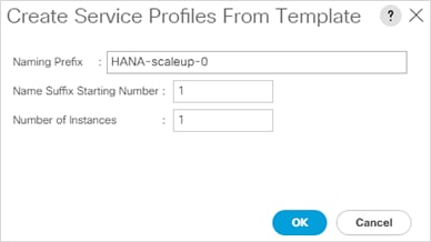
7. Click OK to create the service profiles.
8. Click OK in the confirmation message.
This section explains how to configure the Cisco MDS 9000s for use in a FlexPod environment. Follow the steps precisely because failure to do so could result in an improper configuration.
If directly connecting storage to the Cisco UCS fabric interconnects, skip this section.
Follow the physical connectivity guidelines for FlexPod as explained in the section FlexPod Cabling.
It’s useful to prepare a connectivity diagram of the FC setup for quick reference. The Cisco MDS specific connectivity in the validation setup is as shown below (the diagram shows physical and it’s infra-svm LIFs of NetApp array):
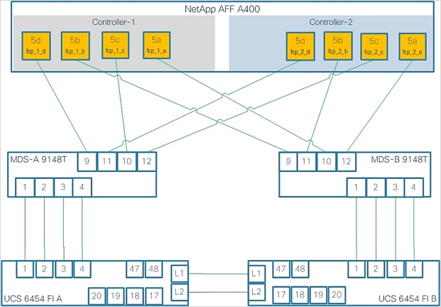
The procedures in this section describe how to configure the Cisco Nexus switches for use in a base FlexPod environment. This procedure assumes you are using the Cisco MDS 9148T with NX-OS 8.4(1).
Cisco MDS 9148T A
To set up the initial configuration for the Cisco MDS A switch, <mds-A-hostname>, follow these steps:
![]() On initial boot and connection to the serial or console port of the switch, the NX-OS setup should automatically start and attempt to enter Power on Auto Provisioning. Enter y to get to the System Admin Account Setup.
On initial boot and connection to the serial or console port of the switch, the NX-OS setup should automatically start and attempt to enter Power on Auto Provisioning. Enter y to get to the System Admin Account Setup.
1. Configure the switch using the command line.
---- System Admin Account Setup ----
Do you want to enforce secure password standard (yes/no) [y]: Enter
Enter the password for "admin": <password>
Confirm the password for "admin": <password>
Would you like to enter the basic configuration dialog (yes/no): yes
Create another login account (yes/no) [n]: Enter
Configure read-only SNMP community string (yes/no) [n]: Enter
Configure read-write SNMP community string (yes/no) [n]: Enter
Enter the switch name : <mds-A-hostname>
Continue with Out-of-band (mgmt0) management configuration? (yes/no) [y]: Enter
Mgmt0 IPv4 address : <mds-A-mgmt0-ip>
Mgmt0 IPv4 netmask : <mds-A-mgmt0-netmask>
Configure the default gateway? (yes/no) [y]: Enter
IPv4 address of the default gateway : <mds-A-mgmt0-gw>
Configure advanced IP options? (yes/no) [n]: Enter
Enable the ssh service? (yes/no) [y]: Enter
Type of ssh key you would like to generate (dsa/rsa) [rsa]: Enter
Number of rsa key bits <1024-2048> [1024]: Enter
Enable the telnet service? (yes/no) [n]: Enter
Configure congestion/no_credit drop for fc interfaces? (yes/no) [y]: Enter
Enter the type of drop to configure congestion/no_credit drop? (con/no) [c]: Enter
Enter milliseconds in multiples of 10 for congestion-drop for logical-type edge
in range (<200-500>/default), where default is 500. [d]: Enter
Enable the http-server? (yes/no) [y]: Enter
Configure clock? (yes/no) [n]: Enter
Configure timezone? (yes/no) [n]: Enter
Configure summertime? (yes/no) [n]: Enter
Configure the ntp server? (yes/no) [n]: yes
NTP server IPv4 address : <nexus-A-mgmt0-ip>
Configure default switchport interface state (shut/noshut) [shut]: Enter
Configure default switchport trunk mode (on/off/auto) [on]: auto
Configure default switchport port mode F (yes/no) [n]: yes
Configure default zone policy (permit/deny) [deny]: Enter
Enable full zoneset distribution? (yes/no) [n]: Enter
Configure default zone mode (basic/enhanced) [basic]: Enter
2. Review the configuration.
Would you like to edit the configuration? (yes/no) [n]: Enter
Use this configuration and save it? (yes/no) [y]: Enter
Cisco MDS 9148T B
To set up the initial configuration for the Cisco MDS B switch, <mds-B-hostname>, follow these steps:
On initial boot and connection to the serial or console port of the switch, the NX-OS setup should automatically start and attempt to enter Power on Auto Provisioning. Enter y to get to the System Admin Account Setup.
1. Configure the switch using the command line.
---- System Admin Account Setup ----
Do you want to enforce secure password standard (yes/no) [y]: Enter
Enter the password for "admin": <password>
Confirm the password for "admin": <password>
Would you like to enter the basic configuration dialog (yes/no): yes
Create another login account (yes/no) [n]: Enter
Configure read-only SNMP community string (yes/no) [n]: Enter
Configure read-write SNMP community string (yes/no) [n]: Enter
Enter the switch name : <mds-B-hostname>
Continue with Out-of-band (mgmt0) management configuration? (yes/no) [y]: Enter
Mgmt0 IPv4 address : <mds-B-mgmt0-ip>
Mgmt0 IPv4 netmask : <mds-B-mgmt0-netmask>
Configure the default gateway? (yes/no) [y]: Enter
IPv4 address of the default gateway : <mds-B-mgmt0-gw>
Configure advanced IP options? (yes/no) [n]: Enter
Enable the ssh service? (yes/no) [y]: Enter
Type of ssh key you would like to generate (dsa/rsa) [rsa]: Enter
Number of rsa key bits <1024-2048> [1024]: Enter
Enable the telnet service? (yes/no) [n]: Enter
Configure congestion/no_credit drop for fc interfaces? (yes/no) [y]: Enter
Enter the type of drop to configure congestion/no_credit drop? (con/no) [c]: Enter
Enter milliseconds in multiples of 10 for congestion-drop for logical-type edge
in range (<200-500>/default), where default is 500. [d]: Enter
Enable the http-server? (yes/no) [y]: Enter
Configure clock? (yes/no) [n]: Enter
Configure timezone? (yes/no) [n]: Enter
Configure summertime? (yes/no) [n]: Enter
Configure the ntp server? (yes/no) [n]: yes
NTP server IPv4 address : <nexus-A-mgmt0-ip>
Configure default switchport interface state (shut/noshut) [shut]: Enter
Configure default switchport trunk mode (on/off/auto) [on]: auto
Configure default switchport port mode F (yes/no) [n]: yes
Configure default zone policy (permit/deny) [deny]: Enter
Enable full zoneset distribution? (yes/no) [n]: Enter
Configure default zone mode (basic/enhanced) [basic]: Enter
2. Review the configuration.
Would you like to edit the configuration? (yes/no) [n]: Enter
Use this configuration and save it? (yes/no) [y]: Enter
FlexPod Cisco MDS Switch Configuration
Cisco MDS 9148T A and Cisco MDS 9148T B
To enable the correct features on the Cisco MDS switches, follow these steps:
1. Log in as admin.
2. Run the following commands:
configure terminal
feature npiv
feature fport-channel-trunk
Cisco MDS 9148T A
To configure individual ports and port-channels for switch A, follow this step:
1. From the global configuration mode, run the following commands:
switchport description <st-clustername>-1:5d
switchport speed 32000
switchport trunk mode off
no shutdown
exit
interface fc1/10
switchport description <st-clustername>-1:5c
switchport speed 32000
switchport trunk mode off
no shutdown
exit
interface fc1/11
switchport description <st-clustername>-2:5d
switchport speed 32000
switchport trunk mode off
no shutdown
exit
interface fc1/12
switchport description <st-clustername>-2:5c
switchport speed 32000
switchport trunk mode off
no shutdown
exit
interface port-channel10
switchport description <ucs-clustername>-a
channel mode active
switchport trunk allowed vsan <vsan-a-id>
no shutdown
exit
interface fc1/1
switchport description <ucs-clustername>-a:1/1
channel-group 10
no shutdown
exit
interface fc1/2
switchport description <ucs-clustername>-a:1/2
channel-group 10
no shutdown
exit
interface fc1/3
switchport description <ucs-clustername>-a:1/3
channel-group 10
no shutdown
exit
interface fc1/4
switchport description <ucs-clustername>-a:1/4
channel-group 10
no shutdown
exit
Cisco MDS 9148T B
To configure individual ports and port-channels for switch B, follow this step:
1. From the global configuration mode, run the following commands:
interface fc1/9
switchport description <st-clustername>-1:5b
switchport speed 32000
switchport trunk mode off
no shutdown
exit
interface fc1/10
switchport description <st-clustername>-1:5a
switchport speed 32000
switchport trunk mode off
no shutdown
exit
interface fc1/11
switchport description <st-clustername>-2:5b
switchport speed 32000
switchport trunk mode off
no shutdown
exit
interface fc1/12
switchport description <st-clustername>-2:5a
switchport speed 32000
switchport trunk mode off
no shutdown
exit
interface port-channel20
switchport description <ucs-clustername>-b
channel mode active
switchport trunk allowed vsan <vsan-b-id>
no shutdown
exit
interface fc1/1
switchport description <ucs-clustername>-b:1/1
channel-group 20
no shutdown
exit
interface fc1/2
switchport description <ucs-clustername>-b:1/2
channel-group 20
no shutdown
exit
interface fc1/3
switchport description <ucs-clustername>-b:1/3
channel-group 20
no shutdown
exit
interface fc1/4
switchport description <ucs-clustername>-b:1/1:1/4
channel-group 20
no shutdown
exit
![]() If VSAN trunking is not being used between the Cisco UCS Fabric Interconnects and the MDS switches, do not enter “switchport trunk allowed vsan <vsan-b-id>” for interface port-channel20. Note also that the default setting of switchport trunk mode auto is being used for the port channel.
If VSAN trunking is not being used between the Cisco UCS Fabric Interconnects and the MDS switches, do not enter “switchport trunk allowed vsan <vsan-b-id>” for interface port-channel20. Note also that the default setting of switchport trunk mode auto is being used for the port channel.
Cisco MDS 9148T A
To create the necessary VSANs for fabric A and add ports to them, follow this step:
1. From the global configuration mode, run the following commands:
vsan database
vsan <vsan-a-id>
vsan <vsan-a-id> name Fabric-A
exit
zone smart-zoning enable vsan <vsan-a-id>
vsan database
vsan <vsan-a-id> interface fc1/9
vsan <vsan-a-id> interface fc1/10
vsan <vsan-a-id> interface fc1/11
vsan <vsan-a-id> interface fc1/12
vsan <vsan-a-id> interface port-channel10
exit
Cisco MDS 9148T B
To create the necessary VSANs for fabric B and add ports to them, follow this step:
1. From the global configuration mode, run the following commands:
vsan database
vsan <vsan-b-id>
vsan <vsan-b-id> name Fabric-B
exit
zone smart-zoning enable vsan <vsan-b-id>
vsan database
vsan <vsan-b-id> interface fc1/9
vsan <vsan-b-id> interface fc1/10
vsan <vsan-b-id> interface fc1/11
vsan <vsan-b-id> interface fc1/12
vsan <vsan-b-id> interface port-channel20
exit
![]() It may be necessary to log into Cisco UCS Manager and disable and enable the FC port-channel interfaces to get the port-channels to come up.
It may be necessary to log into Cisco UCS Manager and disable and enable the FC port-channel interfaces to get the port-channels to come up.
Cisco MDS 9148T A
To create device aliases for Fabric A that will be used to create zones, follow these steps:
1. LIFs information can be acquired from the array configuration.
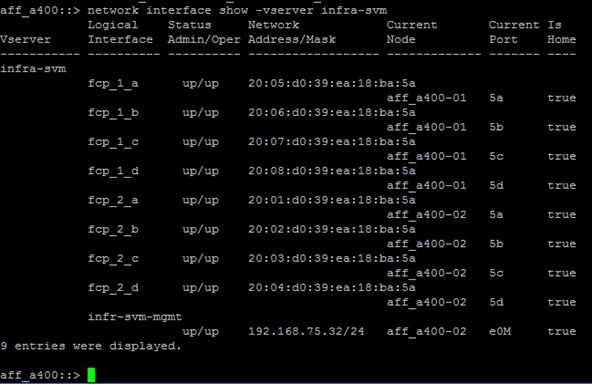
2. From the global configuration mode, run the following commands:
device-alias mode enhanced
device-alias database
device-alias name infra-svm-fcp-1-d pwwn <fcp-lif-1d-wwpn>
device-alias name infra-svm-fcp-1-c pwwn <fcp-lif-1c-wwpn>
device-alias name infra-svm-fcp-2-d pwwn <fcp-lif-2d-wwpn>
device-alias name infra-svm-fcp-2-c pwwn <fcp-lif-2c-wwpn>
device-alias name HANA-node-01-vHBA-A pwwn <HANA-01-Fab-A-wwpn>
device-alias name HANA-node-02-vHBA-A pwwn <HANA-02-Fab-A-wwpn>
device-alias name HANA-node-03-vHBA-A pwwn <HANA-03-Fab-A-wwpn>
device-alias name HANA-node-04-vHBA-A pwwn <HANA-04-Fab-A-wwpn>
device-alias commit
Cisco MDS 9148T B
To create device aliases for Fabric B that will be used to create zones, this step:
1. From the global configuration mode, run the following commands:
device-alias mode enhanced
device-alias database
device-alias name infra-svm-fcp-1-b pwwn <fcp-lif-1b-wwpn>
device-alias name infra-svm-fcp-1-a pwwn <fcp-lif-1a-wwpn>
device-alias name infra-svm-fcp-2-b pwwn <fcp-lif-2b-wwpn>
device-alias name infra-svm-fcp-2-a pwwn <fcp-lif-2a-wwpn>
device-alias name HANA-node-01-vHBA-B pwwn <HANA-01-Fab-B-wwpn>
device-alias name HANA-node-02-vHBA-B pwwn <HANA-02-Fab-B-wwpn>
device-alias name HANA-node-03-vHBA-B pwwn <HANA-03-Fab-B-wwpn>
device-alias name HANA-node-04-vHBA-B pwwn <HANA-04-Fab-B-wwpn>
device-alias commit
![]() infra-svm specific zone is solely used of boot purposes.
infra-svm specific zone is solely used of boot purposes.
To create the infra-svm specific zone that is used solely for booting purpose follow these steps:
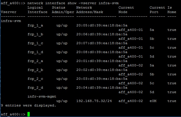
Cisco MDS 9148T A
To create the required zones and zoneset on Fabric A, run the following commands:
1. LIFs information can be acquired from the array configuration.
configure terminal
zone name infra-svm-Fabric-A vsan <vsan-a-id>
member device-alias HANA-node-01-vHBA-A init
member device-alias HANA-node-02-vHBA-A init
member device-alias HANA-node-03-vHBA-A init
member device-alias HANA-node-04-vHBA-A init
member device-alias infra-svm-fcp-1-d target
member device-alias infra-svm-fcp-1-c target
member device-alias infra-svm-fcp-2-d target
member device-alias infra-svm-fcp-2-c target
exit
zoneset name Fabric-A vsan <vsan-a-id>
member infra-svm-Fabric-A
exit
zoneset activate name Fabric-A vsan <vsan-a-id>
show zoneset active
copy r s
![]() Since Smart Zoning is enabled, a single zone is created with all host boot initiators and boot targets for the Infra-SVM instead of creating a separate zone for each host with the host initiator and boot targets. If a new host is added, its boot initiator can simply be added to the single zone in each MDS switch and then the zoneset reactivated. If another SVM is added to the FlexPod with FC targets, a new zone can be added for that SVM. Initiator groups ensure secure host level access to intended LUNs.
Since Smart Zoning is enabled, a single zone is created with all host boot initiators and boot targets for the Infra-SVM instead of creating a separate zone for each host with the host initiator and boot targets. If a new host is added, its boot initiator can simply be added to the single zone in each MDS switch and then the zoneset reactivated. If another SVM is added to the FlexPod with FC targets, a new zone can be added for that SVM. Initiator groups ensure secure host level access to intended LUNs.
Cisco MDS 9148T B
To create the required zones and zoneset on Fabric B, run the following commands:
configure terminal
zone name infra-svm-Fabric-B vsan <vsan-b-id>
member device-alias HANA-node-01-vHBA-B init
member device-alias HANA-node-02-vHBA-B init
member device-alias HANA-node-03-vHBA-B init
member device-alias HANA-node-04-vHBA-B init
member device-alias infra-svm-fcp-1-b target
member device-alias infra-svm-fcp-1-a target
member device-alias infra-svm-fcp-2-b target
member device-alias infra-svm-fcp-2-a target
exit
zoneset name Fabric-B vsan <vsan-b-id>
member infra-svm-Fabric-B
exit
zoneset activate name Fabric-B vsan <vsan-b-id>
exit
show zoneset active
copy r s
Create hana-svm Specific Zone for HANA Persistence LUNs Presentation
To create the hana-svm specific zone that is used solely for presentation of HANA persistence LUNs to designated hosts, you need the information of the logical ports it is connected to and the LIF information. The connectivity diagram helps map the LIFs corresponding to the hana-svm. The LIF information is shown in the array command line:
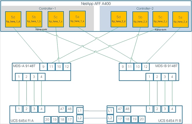
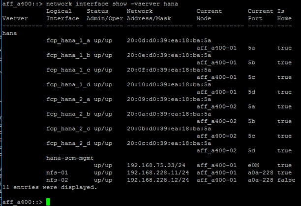
Cisco MDS 9148T A
To add device aliases for LIFs specific to hana-svm for Fabric A that will be used to create zone, follow this step:
1. From the global configuration mode, run the following commands:
device-alias mode enhanced
device-alias database
device-alias name hana-svm-fcp-1-d pwwn <lif-fcp_hana_1_d-wwpn>
device-alias name hana-svm-fcp-1-c pwwn <lif-fcp_hana_1_c-wwpn>
device-alias name hana-svm-fcp-2-d pwwn <lif-fcp_hana_2_d-wwpn>
device-alias name hana-svm-fcp-2-c pwwn <lif-fcp-hana_2_c-wwpn>
device-alias commit
Cisco MDS 9148T A
To create the required zones and zoneset on Fabric A, run the following commands:
configure terminal
zone name hana-svm-Fabric-A vsan <vsan-a-id>
member device-alias HANA-node-01-vHBA-A init
member device-alias HANA-node-02-vHBA-A init
member device-alias HANA-node-03-vHBA-A init
member device-alias HANA-node-04-vHBA-A init
member device-alias hana-svm-fcp-1-d target
member device-alias hana-svm-fcp-1-c target
member device-alias hana-svm-fcp-2-d target
member device-alias hana-svm-fcp-2-c target
exit
zoneset name Fabric-A vsan <vsan-a-id>
member hana-svm-Fabric-A
exit
zoneset activate name Fabric-A vsan <vsan-a-id>
show zoneset active
copy r s
![]() Since Smart Zoning is enabled, a single zone is created with all host boot initiators and boot targets for the hana-svm instead of creating a separate zone for each host with the host initiator and boot targets. If a new host is added, its boot initiator can simply be added to the single zone in each MDS switch and then the zoneset reactivated. If another SVM is added to the FlexPod with FC targets, a new zone can be added for that SVM.
Since Smart Zoning is enabled, a single zone is created with all host boot initiators and boot targets for the hana-svm instead of creating a separate zone for each host with the host initiator and boot targets. If a new host is added, its boot initiator can simply be added to the single zone in each MDS switch and then the zoneset reactivated. If another SVM is added to the FlexPod with FC targets, a new zone can be added for that SVM.
Cisco MDS 9148T B
To add device aliases for LIFs specific to hana-svm for Fabric B that will be used to create zone, follow this step:
1. From the global configuration mode, run the following commands:
device-alias mode enhanced
device-alias database
device-alias name hana-svm-fcp-1-b pwwn <lif-fcp_hana_1_b-wwpn>
device-alias name hana-svm-fcp-1-a pwwn <lif-fcp_hana_1_a-wwpn>
device-alias name hana-svm-fcp-2-b pwwn <lif-fcp_hana_2_b-wwpn>
device-alias name hana-svm-fcp-2-a pwwn <lif-fcp-hana_2_a-wwpn>
device-alias commit
To create the required zone and zoneset on Fabric B, run the following commands:
configure terminal
zone name hana-svm-Fabric-B vsan <vsan-b-id>
member device-alias HANA-node-01-vHBA-B init
member device-alias HANA-node-02-vHBA-B init
member device-alias HANA-node-03-vHBA-B init
member device-alias HANA-node-04-vHBA-B init
member device-alias hana-svm-fcp-1-b target
member device-alias hana-svm-fcp-1-a target
member device-alias hana-svm-fcp-2-b target
member device-alias hana-svm-fcp-2-a target
exit
zoneset name Fabric-B vsan <vsan-b-id>
member hana-svm-Fabric-B
exit
zoneset activate name Fabric-B vsan <vsan-b-id>
exit
show zoneset active
copy r s
This section details the preparation of HANA nodes based on SLES for SAP Applications 15 SP2 and RHEL 8.1 and provides the Linux Operating System installation procedure using SAN Boot and includes operating system customization to fulfill all SAP HANA requirements. If you plan to install Red Hat Enterprise Linux for SAP Solutions skip the first SUSE Linux Enterprise Server for SAP Applications installation section.
SLES for SAP Applications 15 SP2
SUSE® Linux Enterprise Server for SAP Applications is the reference platform for the software development of SAP. It is optimized for SAP applications like SAP HANA. The installation follows the installation workflow documented in chapter 3.1 of https://documentation.suse.com/sles-sap/15-SP2/html/SLES-SAP-guide/index.html and this section lists where the lab installation deviates from the installation workflow.
The supplement SUSE information available from the SAP notes system is as follows:
● SAP Note 2578899 - SUSE Linux Enterprise Server 15: Installation Note
● SAP Note 2684254 - SAP HANA DB: Recommended OS settings for SLES 15 for SAP Applications 15
● SAP Note 1275776 - Linux: Preparing SLES for SAP environments
Download the ISO image from https://download.suse.com.
To map the installation ISO image in the KVM console, follow these steps:
1. In the Navigation pane of the Cisco UCS Manager, click Servers.
2. Select Service Profile > root > Sub-Organization > HANA > HANA-Server01.
3. In the Actions section click KVM Console.
4. Choose Virtual Media > Activate Virtual Devices.
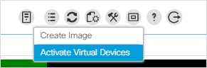
5. For Unencrypted Virtual Media Session, select Accept this Session and then click Apply.
6. Click Virtual Media and choose Map CD/DVD.
7. Click Browse to navigate to the ISO media location. Select SLE-15-SP2-Full-x86_64-GM-Media1..SO and click Open.
8. Click Map Device.
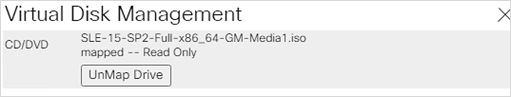
9. In the KVM Console menu, click Boot Server.
10. During the VIC FC boot driver verification at the server boot time the NetApp array target WWPN numbers are listed during the connection verification.
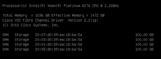
11. The System will automatically boot from the ISO image into the installation wizard.
12. Follow the SUSE Linux Enterprise installation workflow and choose SUSE Linux Enterprise Server for SAP Applications 15 SP2.
13. Language, Keyboard and Product Selection – Choose the desired Language and Keyboard layout. Select SLES for SAP Applications 15 SP2 for Product to Install. Click Next.
14. On the Agreement page, tick the agree checkbox and click Next.
15. On the network settings screen configure the management network interface:
16. Identify the Ethernet device to vNIC interface mapping first from the Cisco UCS Manager:
a. In the Navigation pane of UCSM, click Servers.
b. Select Service Profile > root > Sub-Organizations > HANA > HANA-Server01.
c. In the network tab, scroll down to the vNIC section and list the vNICs with their MAC addresses.
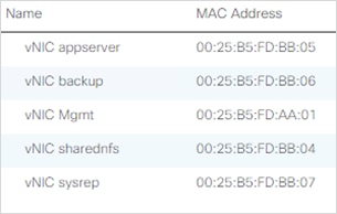
d. Note down the MAC address of the HANA-Mgmt vNIC, in this lab installation “00:25:B5:FD:AA:01”
17. In the SUSE network settings screen, find the network interface with the same MAC address, in this lab installation eth2 and click Edit.
18. Provide the IP address <var_server01_mgmt_ip>, the subnet mask <var_oob_vlan_net> and the fully qualified host name <var_server01_mgmt_hostname> in the General tab. Click Next.
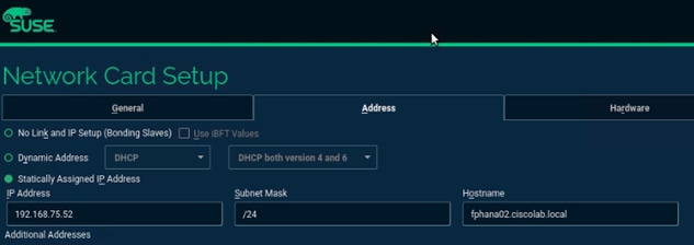
19. Select the Hostname/DNS tab.
20. Provide the server hostname: <var_server01_hostname>
21. Change the Set Hostname from the DHCP drop-down list to no.
22. Enter the name server IP: <var_nameserver_ip>
23. Enter the domain name in the domain search field: <var_dns_domain_name>
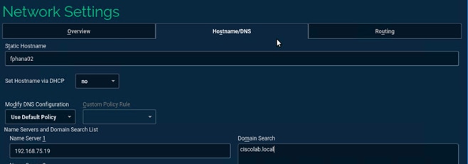
24. Choose the Routing table.
25. Enter the default IPv4 Gateway IP address: <var_os_default_IPv4_gateway> and change the device field to:
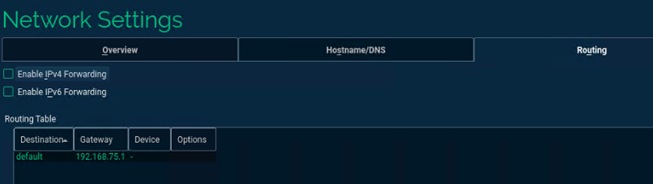
26. Configure the IP addresses for the rest of networks configured.
27. Click Next and continue with the SUSE Linux Enterprise installation workflow.
28. During the System Probing stage, for the pop-up “The system seems to have multipath hardware. Do you want to activate multipath?” click Yes.
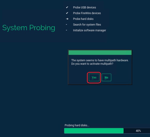
29. Skip the registration for now. Click OK and then click Next.
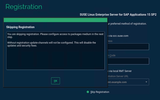
30. Extension and Module Selection. Choose as shown below and click Next.
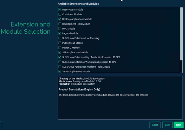
31. Add-On Product Installation – verify the selection and click Next.
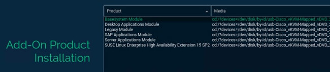
32. System Role – Select SLES for SAP Applications.
33. Choose OS Edition – uncheck both options. Click Next.
34. Suggested Partitioning:
a. On the Suggested Partitioning dialog select Expert Partitioner and start with the current proposal.
b. Under Hostname > Volume Management delete all volumes.
c. Under Hostname > Hard Disks, look for the 100G NetApp device for the boot LUN. Select the multipath device. The Used devices tab list the NetApp LUN scsi devices.
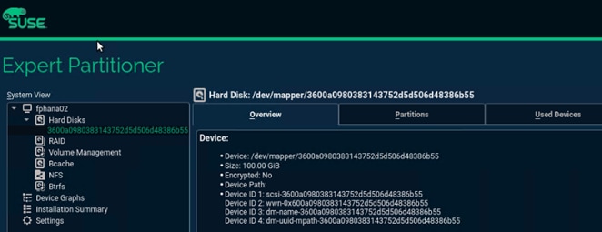
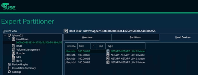
d. Click the middle Partitions tab. Under Partition Table select Create new partition table.
e. Choose GPT as new Partition Table Type and click Next.
f. Change to the Partitions tab and click Add Partition.
g. Choose 0.5 GiB as new partition custom size and click Next.
h. Choose the Role EFI Boot Partition and click Next.
i. Keep the default selections -> Format the device file system in format type FAT and mount the device mount point /boot/efi. Click Next.
j. Create another partition and click Add Partition.
k. Choose Custom Size of 2GiB and Click Next. Select Swap role and click Next. Accept the default formatting options.
l. Create another partition and click Add Partition.
m. Allocate the remaining maximum size (97.49 GiB) and click Next.
n. Choose the role Operating System and click Next.
o. For the Formatting Options, choose appropriate filesystem for root filesystem and Mount Device as / [root filesystem]. XFS was used in the validation setup.
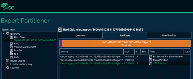
p. Accept the changes and leave the expert partitioner. Suggested Partitioning page now summarizes the configuration.
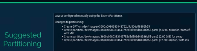
q. Click Next to accept the suggested partitioning and continue with the SUSE Linux Enterprise installation workflow.
35. Set the Clock and Timezone as required.
36. Provide the system administrator root password <var_os_root_pw> and click Next.
37. Several customization steps are recommended from the Installation Settings screen.
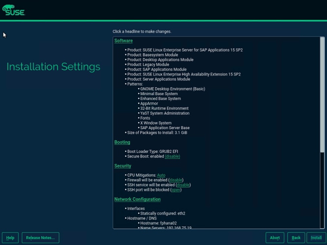
38. Click Software to apply the following changes:
a. Deselect GNOME Desktop Environment.
b. Select Fonts.
c. Select X Window System.
d. (Optional)Select Enhanced Base System.
e. Select SAP HANA Server Base.
f. Deselect primary function SAP Application Sever Base.
g. (Optional) Select primary function high availability.
39. Under Security > Firewall will be enabled click disable.
40. Click Kdump to disable kdump.
41. Set Default system target to text mode.
42. Click Install and select Install again on the Confirmation pop-up.
43. The server will reboot automatically to finish the installation. Click abort on the post-install configuration wizard.
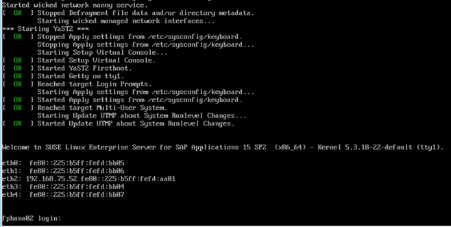
SLES for SAP 15 Post Installation
Apply the post installation steps to prepare the operating system for SAP HANA installation. Connect to the SSH server terminal.
Network Interface Configuration
To configure the network interface, follow these steps:
1. Configure any remaining network interfaces.
# yast lan
2. In the SUSE network settings screen, find the network interface with the same MAC address and click edit to provide the appropriate IP address matching to the correct VLAN and provide a fully qualified hostname.
3. Verify all interfaces come up successfully.
# ip link show | egrep 'state|eth[:digit]' | tail -n +2
2: eth0: <BROADCAST,MULTICAST,UP,LOWER_UP> mtu 9000 qdisc mq state UP mode DEFAULT group default qlen 1000
3: eth1: <BROADCAST,MULTICAST,UP,LOWER_UP> mtu 9000 qdisc mq state UP mode DEFAULT group default qlen 1000
4: eth2: <BROADCAST,MULTICAST,UP,LOWER_UP> mtu 1500 qdisc mq state UP mode DEFAULT group default qlen 1000
5: eth3: <BROADCAST,MULTICAST,UP,LOWER_UP> mtu 9000 qdisc mq state UP mode DEFAULT group default qlen 1000
6: eth4: <BROADCAST,MULTICAST,UP,LOWER_UP> mtu 9000 qdisc mq state UP mode DEFAULT group default qlen 1000
4. Verify the default gateway setting.
# vi /etc/sysconfig/network/routes
default 192.168.75.1 - -
5. Perform a network service restart to enact the updates relating to IP settings. With admin IP configuration, you would be able to SSH to the host.
# service network restart
6. Update the /etc/hosts with IP address of all networks and their alias hostnames:
fphana02:/etc/sysconfig/network # cat /etc/hosts
#
# hosts This file describes a number of hostname-to-address
# mappings for the TCP/IP subsystem. It is mostly
# used at boot time, when no name servers are running.
# On small systems, this file can be used instead of a
# "named" name server.
# Syntax:
#
# IP-Address Full-Qualified-Hostname Short-Hostname
#
127.0.0.1 localhost
# special IPv6 addresses
::1 localhost ipv6-localhost ipv6-loopback
fe00::0 ipv6-localnet
ff00::0 ipv6-mcastprefix
ff02::1 ipv6-allnodes
ff02::2 ipv6-allrouters
ff02::3 ipv6-allhosts
#
## AppServer Network
#
192.168.221.52 fphana02a.ciscolab.local fphana02a
#
## Admin Network
#
192.168.75.52 fphana02.ciscolab.local fphana02
#
## Backup Network
#
192.168.222.52 fphana02b.ciscolab.local fphana02b
#
## Replication Network
#
192.168.225.52 fphana02r.ciscolab.local fphana02r
#
## HANA -shared Network
#
192.168.228.52 fphana02s.ciscolab.local fphana02s
Proxy Configuration
To configure the proxy, follow this step:
1. Enter and test your proxy configuration.
# yast proxy
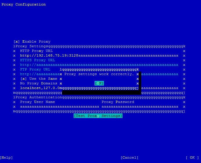
![]() Reboot the system to also (effect disabling ipv6 if applicable) before going ahead with the registration step.
Reboot the system to also (effect disabling ipv6 if applicable) before going ahead with the registration step.
SLES System Update
To update the SLES system, follow these steps:
1. Register the system with SUSE to get the latest patches. The system must have access to the Internet to proceed with this step.
# SUSEConnect -r <<reg-code>>
2. Update the system with the following command.
# zypper update
3. Follow the on-screen instructions to complete the update process. Reboot the server, as suggested, and log in to the system again.
4. Reboot the system.
Implement SAP Notes Recommendations
To optimize the HANA DB with SLES for SAP 15 SP2, follow the instructions in the SAP Note 2684254:
1. SAP Note 1275776 describes how to apply recommended operating system settings for running SAP applications on SLES. There are three ways to implement the same – sapconf, sapture or manually. It is important to note when using sapconf or saptune, verify that parameters handled by these tools are not configured elsewhere (for example, boot parameter, sysctl.conf, and so on). This can cause inconsistent system behavior and makes debugging very difficult.
2. This CVD uses the saptune (version 2) method which can prepare the operating system for SAP applications based on implementing specific SAP Notes.
3. Install saptune:
#zypper install saptune
4. Configuration – activate saptune:
#saptune daemon start
5. All available solutions and notes can be listed with:
#saptune solution list
6. Apply SAP HANA solution/notes:
#saptune solution apply HANA
7. Verify the solution applied:
# saptune solution verify HANA
Update Cisco fnic/enic Drivers
Based on the serer type/model, processor version, OS release and version information download the firmware bundle corresponding to the UCS Server firmware installed from the Cisco UCS Hardware and Software Compatibility site.
To extract the rpm files of the fnic and enic driver from the driver bundle and copy them to the server, follow these steps:
1. Verify the current driver:
# cat /sys/module/enic/version
2.3.0.53
# cat /sys/module/fnic/version
1.6.0.47
2. RPM install the drivers:
# rpm -ivh cisco-enic-usnic-kmp-default-4.0.0.8_k4.12.14_195-802.24.x86_64.rpm
# rpm -ivh cisco-fnic-kmp-default-2.0.0.60-141.0.x86_64.rpm
3. Reboot the server:
Verify the driver installation after the reboot.
# cat /sys/module/enic/version
4.0.0.8-802.24
# cat /sys/module/fnic/version
2.0.0.60-141.0
Enable System Monitoring (Optional)
To enable the system monitoring, follow these steps:
1. Enable system utilization monitoring:
# systemctl enable sysstat
# systemctl start sysstat
2. (Optional) Install rsyslog to bring the /var/log/messages file back:
# zypper in rsyslog
# systemctl enable rsyslog
# systemctl start rsyslog
Persistent Memory Configuration
Configure and manage Intel Optane DC PMM from the command line with the ipmctl and ndctl utilities. The tools are not installed by default but are required to manage the libnvdimm (non-volatile memory device) sub-system in the Linux kernel.
To install the host tools, open an SSH prompt as root and follow these steps:
1. Install the ipmctl host utility:
# zypper in ipmctl
2. Install the ndctl utility:
# zypper in ndctl
3. Verify the persistent memory modules have been discovered and the software can communicate with them:
# ipmctl show -dimm
DimmID | Capacity | HealthState | ActionRequired | LockState | FWVersion
==============================================================================
0x0011 | 252.4 GiB | Healthy | 0 | Disabled | 01.02.00.5435
0x0021 | 252.4 GiB | Healthy | 0 | Disabled | 01.02.00.5435
0x0001 | 252.4 GiB | Healthy | 0 | Disabled | 01.02.00.5435
0x0111 | 252.4 GiB | Healthy | 0 | Disabled | 01.02.00.5435
0x0121 | 252.4 GiB | Healthy | 0 | Disabled | 01.02.00.5435
0x0101 | 252.4 GiB | Healthy | 0 | Disabled | 01.02.00.5435
0x1011 | 252.4 GiB | Healthy | 0 | Disabled | 01.02.00.5435
0x1021 | 252.4 GiB | Healthy | 0 | Disabled | 01.02.00.5435
0x1001 | 252.4 GiB | Healthy | 0 | Disabled | 01.02.00.5435
0x1111 | 252.4 GiB | Healthy | 0 | Disabled | 01.02.00.5435
0x1121 | 252.4 GiB | Healthy | 0 | Disabled | 01.02.00.5435
0x1101 | 252.4 GiB | Healthy | 0 | Disabled | 01.02.00.5435
0x2011 | 252.4 GiB | Healthy | 0 | Disabled | 01.02.00.5435
0x2021 | 252.4 GiB | Healthy | 0 | Disabled | 01.02.00.5435
0x2001 | 252.4 GiB | Healthy | 0 | Disabled | 01.02.00.5435
0x2111 | 252.4 GiB | Healthy | 0 | Disabled | 01.02.00.5435
0x2121 | 252.4 GiB | Healthy | 0 | Disabled | 01.02.00.5435
0x2101 | 252.4 GiB | Healthy | 0 | Disabled | 01.02.00.5435
0x3011 | 252.4 GiB | Healthy | 0 | Disabled | 01.02.00.5435
0x3021 | 252.4 GiB | Healthy | 0 | Disabled | 01.02.00.5435
0x3001 | 252.4 GiB | Healthy | 0 | Disabled | 01.02.00.5435
0x3111 | 252.4 GiB | Healthy | 0 | Disabled | 01.02.00.5435
0x3121 | 252.4 GiB | Healthy | 0 | Disabled | 01.02.00.5435
0x3101 | 252.4 GiB | Healthy | 0 | Disabled | 01.02.00.5435
4. Add a UDEV rule:
# vi /etc/udev/rules.d/60-persistent-storage.rules
# PMEM devices
KERNEL=="pmem*", ENV{DEVTYPE}=="disk", ATTRS{uuid}=="?*", SYMLINK+="disk/by-id/pmem-$attr{uuid}"
5. Create the goal:
# ipmctl create -goal MemoryMode=0 PersistentMemoryType=AppDirect Reserved=0
The following configuration will be applied:
SocketID | DimmID | MemorySize | AppDirect1Size | AppDirect2Size
==================================================================
0x0000 | 0x0011 | 0.0 GiB | 252.0 GiB | 0.0 GiB
0x0000 | 0x0021 | 0.0 GiB | 252.0 GiB | 0.0 GiB
0x0000 | 0x0001 | 0.0 GiB | 252.0 GiB | 0.0 GiB
0x0000 | 0x0111 | 0.0 GiB | 252.0 GiB | 0.0 GiB
0x0000 | 0x0121 | 0.0 GiB | 252.0 GiB | 0.0 GiB
0x0000 | 0x0101 | 0.0 GiB | 252.0 GiB | 0.0 GiB
0x0001 | 0x1011 | 0.0 GiB | 252.0 GiB | 0.0 GiB
0x0001 | 0x1021 | 0.0 GiB | 252.0 GiB | 0.0 GiB
0x0001 | 0x1001 | 0.0 GiB | 252.0 GiB | 0.0 GiB
0x0001 | 0x1111 | 0.0 GiB | 252.0 GiB | 0.0 GiB
0x0001 | 0x1121 | 0.0 GiB | 252.0 GiB | 0.0 GiB
0x0001 | 0x1101 | 0.0 GiB | 252.0 GiB | 0.0 GiB
0x0002 | 0x2011 | 0.0 GiB | 252.0 GiB | 0.0 GiB
0x0002 | 0x2021 | 0.0 GiB | 252.0 GiB | 0.0 GiB
0x0002 | 0x2001 | 0.0 GiB | 252.0 GiB | 0.0 GiB
0x0002 | 0x2111 | 0.0 GiB | 252.0 GiB | 0.0 GiB
0x0002 | 0x2121 | 0.0 GiB | 252.0 GiB | 0.0 GiB
0x0002 | 0x2101 | 0.0 GiB | 252.0 GiB | 0.0 GiB
0x0003 | 0x3011 | 0.0 GiB | 252.0 GiB | 0.0 GiB
0x0003 | 0x3021 | 0.0 GiB | 252.0 GiB | 0.0 GiB
0x0003 | 0x3001 | 0.0 GiB | 252.0 GiB | 0.0 GiB
0x0003 | 0x3111 | 0.0 GiB | 252.0 GiB | 0.0 GiB
0x0003 | 0x3121 | 0.0 GiB | 252.0 GiB | 0.0 GiB
0x0003 | 0x3101 | 0.0 GiB | 252.0 GiB | 0.0 GiB
Do you want to continue? [y/n]
6. Confirm with Y and reboot the server to apply the new memory allocations.
7. Verify the regions have been created:
# ipmctl show -region
SocketID | ISetID | Persistent | Capacity | FreeCapacity | HealthState
| | MemoryType | | |
=================================================================================
0x0000 | 0xd7d..9c2ccc | AppDirect | 1512.0 GiB | 1512.0 GiB | Healthy
0x0001 | 0xfba..9b2ccc | AppDirect | 1512.0 GiB | 1512.0 GiB | Healthy
0x0002 | 0xc67..af2ccc | AppDirect | 1512.0 GiB | 1512.0 GiB | Healthy
0x0003 | 0x685..9f2ccc | AppDirect | 1512.0 GiB | 1512.0 GiB | Healthy
8. Create a name space for each region; on a 4-socket server invoke the command four times:
# ndctl create-namespace
9. Verify the namespace have been created successfully:
# ndctl list
[
{
"dev":"namespace1.0",
"mode":"fsdax",
"map":"dev",
"size":1598128390144,
"uuid":"81257c85-4410-4def-8dba-3c120943c6b7",
"sector_size":512,
"align":2097152,
"blockdev":"pmem1"
},
{
"dev":"namespace3.0",
"mode":"fsdax",
"map":"dev",
"size":1598128390144,
"uuid":"197dc10f-cd0d-4a84-bba3-f104df3e70be",
"sector_size":512,
"align":2097152,
"blockdev":"pmem3"
},
{
"dev":"namespace0.0",
"mode":"fsdax",
"map":"dev",
"size":1598128390144,
"uuid":"23526924-74bf-4bab-8fd9-27be6190ce56",
"sector_size":512,
"align":2097152,
"blockdev":"pmem0"
},
{
"dev":"namespace2.0",
"mode":"fsdax",
"map":"dev",
"size":1598128390144,
"uuid":"5847f6d4-4a3d-447c-b299-7d0e38c1dcdd",
"sector_size":512,
"align":2097152,
"blockdev":"pmem2"
}
]
10. Construct an XFS file system on the block devices:
# for i in {0..3}; do mkfs.xfs -f -d su=2m,sw=1 -m reflink=0 /dev/pmem$i; done
11. Create directories and mount the block devices using the DAX file system option:
# for i in {0..3}; do mkdir -p /hana/pmem/nvmem$i; done
# for i in {0..3}; do mount -t xfs -o dax,lazytime /dev/pmem0 /hana/pmem/nvmem$i; done
12. Change the permission of the mount points:
# chmod 755 /hana/pmem/nvmem*
# chown <SID>adm:sapsys /hana/pmem/nvmem*
13. Finally add the mount points to /etc/fstab to persist them:
# vi /etc/fstab
/dev/pmem0 /hana/pmem/nvmem0 xfs dax,lazytime 1 2
/dev/pmem1 /hana/pmem/nvmem1 xfs dax,lazytime 1 2
/dev/pmem2 /hana/pmem/nvmem2 xfs dax,lazytime 1 2
/dev/pmem3 /hana/pmem/nvmem3 xfs dax,lazytime 1 2
14. The device names chosen by the kernel are subject to creation order and discovery. For static configuration they usually don’t change, alternatively consider using persistent naming instead to mount the pmem namespace.
# ls -l /dev/disk/by-id/pmem*
lrwxrwxrwx 1 root root 11 Oct 29 15:34 /dev/disk/by-id/pmem-39afa860-5b33-4956-a1ec-1c176cf34608 -> ../../pmem2
lrwxrwxrwx 1 root root 11 Oct 29 15:34 /dev/disk/by-id/pmem-76c312d8-86e0-4f3d-b630-b816f95f4ff8 -> ../../pmem1
lrwxrwxrwx 1 root root 11 Oct 29 15:34 /dev/disk/by-id/pmem-af000a5b-14ac-4f49-a919-c89bc462944d -> ../../pmem3
lrwxrwxrwx 1 root root 11 Oct 29 15:34 /dev/disk/by-id/pmem-df203ae8-13ef-4b65-bd2e-c7f95979493a -> ../../pmem0
The persistent name for a pmem namespace in /etc/fstab will look like the following:
/dev/disk/by-id/pmem-df203ae8-13ef-4b65-bd2e-c7f95979493a /hana/pmem/nvmem0 xfs dax,lazytime 1 2
Red Hat Enterprise Linux 8 (RHEL) is the reference platform for the software deployment of SAP. It is optimized for SAP applications like SAP HANA. Install the operating system as described in the standard RHEL installation guide. This section lists where the lab installation deviates from the installation workflow.
The following is the supplement RHEL information available from the SAP notes system:
● SAP Note 2526952 - Red Hat Enterprise Linux for SAP Solutions
● SAP Note 2772999 - Red Hat Enterprise Linux 8.x: Installation and Configuration
● SAP Note 2777782 - SAP HANA DB: Recommended OS Settings for RHEL 8
![]() RHEL 8 must be installed and configured according to SAP note https://launchpad.support.sap.com/#/notes/2772999
RHEL 8 must be installed and configured according to SAP note https://launchpad.support.sap.com/#/notes/2772999
Download the standard RHEL ISO image from https://access.redhat.com/downloads. To map the installation ISO image in the KVM console, follow these steps:
1. In the Navigation pane of the Cisco UCS Manager, click Servers.
2. Select Service Profile > root > Sub-Organization > HANA > HANA-Server01.
3. In the Actions section click KVM Console.
4. Choose Virtual Media > Activate Virtual Devices.
5. For Unencrypted Virtual Media Session, select Accept this Session and then click Apply.
6. Click Virtual Media and choose Map CD/DVD.
7. Click Browse to navigate to the ISO media location. Select rhel-8.1-x86_64.ISO. Click Open.
8. Click Map Device.

9. In the KVM Console menu, click Boot Server.
10. During the VIC FC boot driver verification at the server boot time the FlexPod target WWPN numbers are listed during the connection verification.
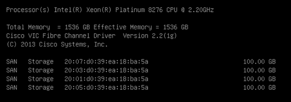
11. The system will automatically boot from the ISO image into the installation wizard.
12. Select Install Red Hat Enterprise Linux 8.1.0 to start the interactive installation process using the server base installation option.
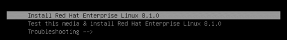
13. At the welcome screen select the language and click Continue.
14. The installation summary page appears. Complete all items before starting the installation.
15. Click Software Selection and use the “Server” Base Environment. No Add-Ons are required during installation. Click Done to return to the main screen.
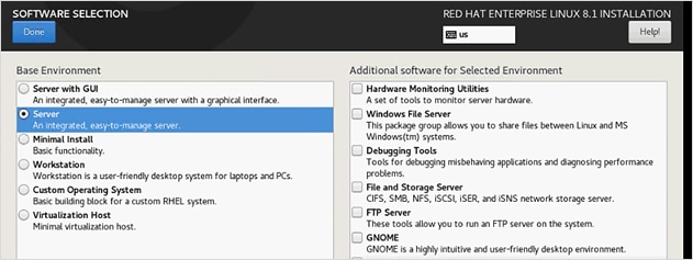
16. Click Time & Date. Select the timezone of your choice and ensure the date and time are set correct.
17. Click Installation Destination and Add a disk.
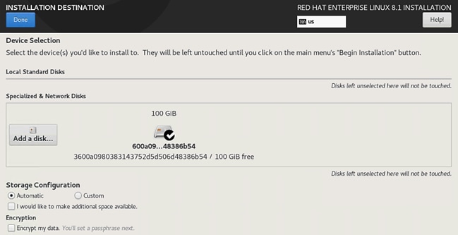
18. Choose the 100 GB boot LUN created before. Click Done.
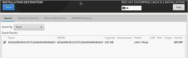
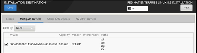
19. Change the radio button Storage Configuration to Custom. Click Done.
20. Change the selection to Standard Partition for “New mount points will use the following partition scheme:” and Click the link to create the file system layout automatically.
21. Delete the home filesystem from the list pressing the minus (-) button.
22. Select the root volume and resize to 94.4 GiB. Click Done.
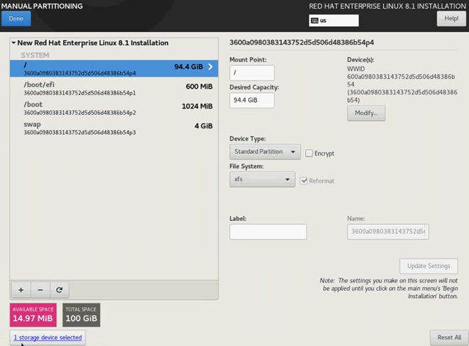
23. Uncheck Enable KDump.
24. Select Network & Host Name:
a. Enter a short host name (cishana01) and click Apply.
b. Identify the Ethernet device to vNIC interface mapping first from the Cisco UCS Manager.
i. In the Navigation pane of UCSM, click Servers.
ii. Select Service Profile > root > Sub-Organizations > HANA > HANA-Server01.
iii. In the network tab, scroll down to the vNIC section and list the vNICs with their MAC addresses.
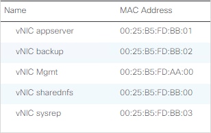
c. Compare the Ethernet hardware addresses and configure the network interfaces.
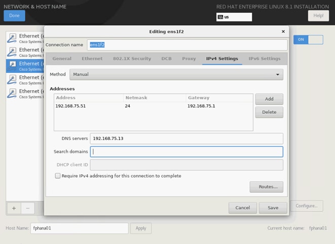
d. Switch the interfaces On and click Done. Repeat the above steps of network configuration for the remaining interfaces.
25. Select System Purpose Role: Red Hat Enterprise Linux Server and the appropriate SLA and usage information. Click Done.
26. Click Begin Installation and provide a root password while the installation is running in the background. Set the Root user password.
27. Before rebooting, unmap the ISO image from the KVM console.
Verify the network configuration; that all networks have been assigned the IP addresses and that they are up. Ensure the network devices configured during installation will be enabled during boot. The following command will change the ONBOOT variable in line 15 of the network configuration file to yes. Verify the successful change. If needed, restart the network to effect any changes and verify the interfaces are up.
# sed -i "15s/no/yes/" /etc/sysconfig/network-scripts/ifcfg-ens*
# grep ONBOOT /etc/sysconfig/network-scripts/ifcfg-ens*
# systemctl restart NetworkManager
# ip addr
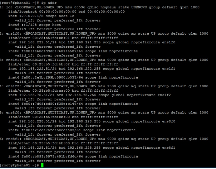
To configure the network, follow these steps:
1. Update the hostname with hostnamectl command:
#hostnamectl set-hostname <hana-node-hostname>
2. Disable Firewall:
#systemctl stop firewalld
#systemctl disable firewalld
3. Disable SELinux:
#sed -i 's/\(SELINUX=enforcing\|SELINUX=permissive\)/SELINUX=disabled/g' /etc/selinux/config
4. Update the /etc/hosts with IP address of all networks and their alias hostnames:
fphana01:~ # vi /etc/hosts
127.0.0.1 localhost localhost.localdomain localhost4 localhost4.localdomain4
::1 localhost localhost.localdomain localhost6 localhost6.localdomain6
#
## AppServer Network
#
192.168.223.51 fphana11a.ciscolab.local fphana01a
#
## Admin Network
#
192.168.75.51 fphana11m.ciscolab.local fphana01m
#
## Backup Network
#
192.168.222.51 fphana11b.ciscolab.local fphana01b
#
## HANA SysRep Network
#
192.168.225.51 fphana11r.ciscolab.local fphana01r
#
## HANA -shared Network
#
192.168.228.51 fphana11s.ciscolab.local fphana01s
5. Add any additional full qualified hostname to the /etc/hosts file as well, like for the client, datasource or internode network based on the use-case.
Review Network Time and Date Configuration
To review the network time and date configuration, follow these steps:
1. During the installation a local NTP server was configured. Review the configuration is working:
# vi /etc/chrony.conf
# Use public servers from the pool.ntp.org project.
# Please consider joining the pool (http://www.pool.ntp.org/join.html).
# pool 2.rhel.pool.ntp.org iburst
server 192.168.75.19 iburst
2. Restart the chronyd service:
# systemctl restart chronyd
# systemctl enable chronyd
3. Validate the service is running and connected to the local time server:
# chronyc sources
Number of sources = 1
MS Name/IP address Stratum Poll Reach LastRx Last sample
===============================================================================
^* 192.168.75.19 2 6 17 36 +607ns[ -113us] +/- 1649us
4. Perform a system reboot to effect SELinux setting:
#reboot
Update the Red Hat System
To update the Red Hat system, follow these steps:
1. Configure a proxy for the subscription-manager:
# vi /etc/rhsm/rhsm.conf
proxy_hostname=proxy.example.com
proxy_port=3128
2. Configure a proxy for the rhn-register and up2date services:
# vi /etc/sysconfig/rhn/up2date
enableProxy=1
httpProxy=proxy.example.com:3128
Refer to the Red Hat KB article https://access.redhat.com/solutions/65300 for more information about how to prepare the system to access the Red Hat Subscription Manager through proxy.
To register the system to the Red Hat portal and attach the SAP HANA subscription, follow the instructions in the Red Hat KB article https://access.redhat.com/solutions/4714781.
To update the Red Hat System, follow these steps:
1. Set the release to the minor release and clear the yum cache and subscribe to the channels:
subscription-manager register --username <username> --password <password>
subscription-manager list --available --all
subscription-manager attach --pool=<<Pool-ID>>
subscription-manager release --set=8.1
subscription-manager repos --disable="*"
subscription-manager repos --enable="rhel-8-for-x86_64-baseos-e4s-rpms" --enable="rhel-8-for-x86_64-appstream-e4s-rpms" --enable="rhel-8-for-x86_64-sap-solutions-e4s-rpms" --enable="rhel-8-for-x86_64-sap-netweaver-e4s-rpms"
subscription-manager repos --enable="rhel-8-for-x86_64-highavailability-e4s-rpms"
2. Check for the available repositories:
[root@fphana01 ~]# yum repolist
Updating Subscription Management repositories.
Last metadata expiration check: 0:00:16 ago on Mon 23 Nov 2020 11:19:52 AM PST.
repo id repo name status
rhel-8-for-x86_64-appstream-e4s-rpms Red Hat Enterprise Linux 8 for x86_64 - AppStream - Updat 9,024
rhel-8-for-x86_64-baseos-e4s-rpms Red Hat Enterprise Linux 8 for x86_64 - BaseOS - Update S 4,060
rhel-8-for-x86_64-highavailability-e4s-rpms Red Hat Enterprise Linux 8 for x86_64 - High Availability 171
rhel-8-for-x86_64-sap-netweaver-e4s-rpms Red Hat Enterprise Linux 8 for x86_64 - SAP NetWeaver - U 15
rhel-8-for-x86_64-sap-solutions-e4s-rpms Red Hat Enterprise Linux 8 for x86_64 - SAP Solutions - U 13
3. Update all packages (including kernel and glibc) to the latest version available in the official RHEL 8 repositories after the initial OS installation:
yum -y update
4. Install other additional required packages required for running SAP HANA on RHEL 8:
yum -y install uuidd libnsl tcsh psmisc nfs-utils bind-utils expect graphviz iptraf-ng krb5-workstation libatomic libcanberra-gtk2 libibverbs libicu libpng12 libssh2 lm_sensors numactl PackageKit-gtk3-module xorg-x11-xauth bind-utils cairo libaio krb5-libs net-tools openssl rsyslog sudo xfsprogs python2 compat-sap-c++-9
5. Reboot the system to effect kernel switch.
reboot
6. Python configuration:
![]() The SAP HANA installer fails to execute the python interpreter if the alternatives are not set.
The SAP HANA installer fails to execute the python interpreter if the alternatives are not set.
alternatives --set python /usr/bin/python2
Optimize the System for SAP HANA Database
To optimize the system for the SAP HANA database, follow these steps:
![]() RHEL 8.1 system must be optimized based on the recommendations to SAP note https://launchpad.support.sap.com/#/notes/2777782
RHEL 8.1 system must be optimized based on the recommendations to SAP note https://launchpad.support.sap.com/#/notes/2777782
7. Configure tuned to use profile “sap-hana:”
a. Install and activate the tuned profile "sap-hana" and check if it is active. With sap-hana profile, the THP is disabled, CPU Governor as well as EPB are set to performance.
b. Install tuned-profiles-sap-hana:
#yum -y install tuned-profiles-sap-hana
c. Start and enable the tuned:
#systemctl start tuned
#systemctl enable tuned
d. Apply the profile for sap-hana:
#tuned-adm profile sap-hana
e. Verify the solution applied:
#tuned-adm active
8. Disable ABRT, Core Dumps and kdump:
![]() The Automatic Bug Reporting Tool (ABRT), which handles application crashes, is not installed by default when installing RHEL 8 with the Server environment group. The corresponding packages are (for example) abrt and abrt-addon-ccpp. If installed, they can be disabled with the following commands:
The Automatic Bug Reporting Tool (ABRT), which handles application crashes, is not installed by default when installing RHEL 8 with the Server environment group. The corresponding packages are (for example) abrt and abrt-addon-ccpp. If installed, they can be disabled with the following commands:
# systemctl stop abrtd
# systemctl stop abrt-ccpp
# systemctl disable abrtd
# systemctl disable abrt-ccp
9. To disable the core file creation for all users, open or create the file /etc/security/limits.d/99-sap.conf and add the following lines:
* soft core 0
* hard core 0
10. Turn off auto-numa balancing. In RHEL 8, auto-numa balancing is switched off by default. To verify, use the following command:
# sysctl kernel.numa_balancing
kernel.numa_balancing = 0
11. To disable automatic NUMA balancing, use the following command:
# echo 0 > /proc/sys/kernel/numa_balancing
12. If package numad is installed on your server, please make sure that it is switched off and disabled:
# systemctl stop numad
# systemctl disable numad
13. Configure C-Stares for lower latency. Append processor.max_cstate=1 intel_idle.max_cstate=1 to the Kernel command line starting with GRUB_CMDLINE_LINUX in /etc/default/grub.
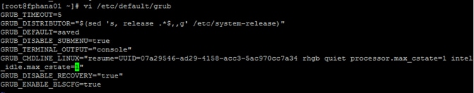
14. Update the GRUB2 configuration file:
# grub2-mkconfig -o /boot/efi/EFI/redhat/grub.cfg
15. Increase kernel.pid_max -> Add the following line to /etc/sysctl.d/sap.conf (create the file if it doesn't already exist): kernel.pid_max=4194304
16. Reboot the system to affect this parameter change.
Update Cisco fnic/enic Drivers
Based on the server type/model, processor version, OS release, and version information, download the firmware bundle corresponding to the Cisco UCS Server firmware installed from the Cisco UCS Hardware and Software Compatibility site.
To extract the rpm files of the fnic and enic driver from the driver bundle and copy them to the server, follow these steps:
1. Verify the current driver:
# cat /sys/module/enic/version
2.3.0.53
# cat /sys/module/fnic/version
1.6.0.47
2. RPM install the drivers:
rpm -ivh kmod-enic-4.0.0.8-802.24.rhel8u1.x86_64.rpm
rpm -ivh kmod-fnic-2.0.0.60-141.0.rhel8u1.x86_64.rpm
3. Reboot the server.
4. Verify the driver installation after the reboot:
# cat /sys/module/enic/version
4.0.0.8-802.24
# cat /sys/module/fnic/version
2.0.0.60-141.0
Persistent Memory Configuration
To configure and manage the Intel Optane DC PMM from the command line with the ipmctl and ndctl utilities, follow these steps. The tools are not installed by default but are required to manage the libnvdimm (non-volatile memory device) sub-system in the Linux kernel.
1. Open an SSH prompt as root to install the host tools.
2. EPEL packages assume that the 'codeready-builder' repository is enabled.
# subscription-manager repos --enable "codeready-builder-for-rhel-8-$(arch)-rpms"
3. Enable the EPEL 8 repository or download the required rpm file from https://dl.fedoraproject.org/pub/epel/8/Everything/x86_64/Packages/.
# yum install https://dl.fedoraproject.org/pub/epel/epel-release-latest-8.noarch.rpm
# yum info ipmctl
# yum -y install ipmctl
4. Install the ndctl utility:
# yum -y install ndctl
5. Verify the persistent memory modules have been discovered and the software can communicate with them:
# ipmctl show -dimm
DimmID | Capacity | LockState | HealthState | FWVersion
===============================================================
0x0001 | 252.454 GiB | Disabled | Healthy | 01.02.00.5435
0x0011 | 252.454 GiB | Disabled | Healthy | 01.02.00.5435
0x0021 | 252.454 GiB | Disabled | Healthy | 01.02.00.5435
0x0101 | 252.454 GiB | Disabled | Healthy | 01.02.00.5435
0x0111 | 252.454 GiB | Disabled | Healthy | 01.02.00.5435
0x0121 | 252.454 GiB | Disabled | Healthy | 01.02.00.5435
0x1001 | 252.454 GiB | Disabled | Healthy | 01.02.00.5435
0x1011 | 252.454 GiB | Disabled | Healthy | 01.02.00.5435
0x1021 | 252.454 GiB | Disabled | Healthy | 01.02.00.5435
0x1101 | 252.454 GiB | Disabled | Healthy | 01.02.00.5435
0x1111 | 252.454 GiB | Disabled | Healthy | 01.02.00.5435
0x1121 | 252.454 GiB | Disabled | Healthy | 01.02.00.5435
0x2001 | 252.454 GiB | Disabled | Healthy | 01.02.00.5435
0x2011 | 252.454 GiB | Disabled | Healthy | 01.02.00.5435
0x2021 | 252.454 GiB | Disabled | Healthy | 01.02.00.5435
0x2101 | 252.454 GiB | Disabled | Healthy | 01.02.00.5435
0x2111 | 252.454 GiB | Disabled | Healthy | 01.02.00.5435
0x2121 | 252.454 GiB | Disabled | Healthy | 01.02.00.5435
0x3001 | 252.454 GiB | Disabled | Healthy | 01.02.00.5435
0x3011 | 252.454 GiB | Disabled | Healthy | 01.02.00.5435
0x3021 | 252.454 GiB | Disabled | Healthy | 01.02.00.5435
0x3101 | 252.454 GiB | Disabled | Healthy | 01.02.00.5435
0x3111 | 252.454 GiB | Disabled | Healthy | 01.02.00.5435
0x3121 | 252.454 GiB | Disabled | Healthy | 01.02.00.5435
6. Add a UDEV rule:
# vi /etc/udev/rules.d/60-persistent-storage.rules
# PMEM devices
KERNEL=="pmem*", ENV{DEVTYPE}=="disk", ATTRS{uuid}=="?*", SYMLINK+="disk/by-id/pmem-$attr{uuid}"
7. Create the goal:
# ipmctl create -goal
The following configuration will be applied:
SocketID | DimmID | MemorySize | AppDirect1Size | AppDirect2Size
==================================================================
0x0000 | 0x0001 | 0.000 GiB | 252.000 GiB | 0.000 GiB
0x0000 | 0x0011 | 0.000 GiB | 252.000 GiB | 0.000 GiB
0x0000 | 0x0021 | 0.000 GiB | 252.000 GiB | 0.000 GiB
0x0000 | 0x0101 | 0.000 GiB | 252.000 GiB | 0.000 GiB
0x0000 | 0x0111 | 0.000 GiB | 252.000 GiB | 0.000 GiB
0x0000 | 0x0121 | 0.000 GiB | 252.000 GiB | 0.000 GiB
0x0001 | 0x1001 | 0.000 GiB | 252.000 GiB | 0.000 GiB
0x0001 | 0x1011 | 0.000 GiB | 252.000 GiB | 0.000 GiB
0x0001 | 0x1021 | 0.000 GiB | 252.000 GiB | 0.000 GiB
0x0001 | 0x1101 | 0.000 GiB | 252.000 GiB | 0.000 GiB
0x0001 | 0x1111 | 0.000 GiB | 252.000 GiB | 0.000 GiB
0x0001 | 0x1121 | 0.000 GiB | 252.000 GiB | 0.000 GiB
0x0002 | 0x2001 | 0.000 GiB | 252.000 GiB | 0.000 GiB
0x0002 | 0x2011 | 0.000 GiB | 252.000 GiB | 0.000 GiB
0x0002 | 0x2021 | 0.000 GiB | 252.000 GiB | 0.000 GiB
0x0002 | 0x2101 | 0.000 GiB | 252.000 GiB | 0.000 GiB
0x0002 | 0x2111 | 0.000 GiB | 252.000 GiB | 0.000 GiB
0x0002 | 0x2121 | 0.000 GiB | 252.000 GiB | 0.000 GiB
0x0003 | 0x3001 | 0.000 GiB | 252.000 GiB | 0.000 GiB
0x0003 | 0x3011 | 0.000 GiB | 252.000 GiB | 0.000 GiB
0x0003 | 0x3021 | 0.000 GiB | 252.000 GiB | 0.000 GiB
0x0003 | 0x3101 | 0.000 GiB | 252.000 GiB | 0.000 GiB
0x0003 | 0x3111 | 0.000 GiB | 252.000 GiB | 0.000 GiB
0x0003 | 0x3121 | 0.000 GiB | 252.000 GiB | 0.000 GiB
Do you want to continue? [y/n]
8. Confirm with Y and reboot the server to apply the new memory allocations.
9. Verify regions had been created:
# ipmctl show -region
SocketID | ISetID | Persistent | Capacity | FreeCapacity | HealthState
| | MemoryType | | |
=================================================================================
0x0000 | 0xd7d..9c2ccc | AppDirect | 1512.0 GiB | 1512.0 GiB | Healthy
0x0001 | 0xfba..9b2ccc | AppDirect | 1512.0 GiB | 1512.0 GiB | Healthy
0x0002 | 0xc67..af2ccc | AppDirect | 1512.0 GiB | 1512.0 GiB | Healthy
0x0003 | 0x685..9f2ccc | AppDirect | 1512.0 GiB | 1512.0 GiB | Healthy
10. Create a name space for each region; on a 4-socket server invoke the command four times:
# ndctl create-namespace
11. Verify the namespace have been created successfully:
# ndctl list
[
{
"dev":"namespace1.0",
"mode":"fsdax",
"map":"dev",
"size":1598128390144,
"uuid":"81257c85-4410-4def-8dba-3c120943c6b7",
"sector_size":512,
"align":2097152,
"blockdev":"pmem1"
},
{
"dev":"namespace3.0",
"mode":"fsdax",
"map":"dev",
"size":1598128390144,
"uuid":"197dc10f-cd0d-4a84-bba3-f104df3e70be",
"sector_size":512,
"align":2097152,
"blockdev":"pmem3"
},
{
"dev":"namespace0.0",
"mode":"fsdax",
"map":"dev",
"size":1598128390144,
"uuid":"23526924-74bf-4bab-8fd9-27be6190ce56",
"sector_size":512,
"align":2097152,
"blockdev":"pmem0"
},
{
"dev":"namespace2.0",
"mode":"fsdax",
"map":"dev",
"size":1598128390144,
"uuid":"5847f6d4-4a3d-447c-b299-7d0e38c1dcdd",
"sector_size":512,
"align":2097152,
"blockdev":"pmem2"
}
]
12. Construct an XFS file system on the block devices:
# for i in {0..3}; do mkfs.xfs -f -d su=2m,sw=1 -m reflink=0 /dev/pmem$i; done
13. Create directories and mount the block devices using the DAX file system option:
# for i in {0..3}; do mkdir -p /hana/pmem/nvmem$i; done
# for i in {0..3}; do mount -t xfs -o dax,lazytime /dev/pmem0 /hana/pmem/nvmem$i; done
14. Change the permission of the mount points:
# chmod 755 /hana/pmem/nvmem*
# chown <SID>adm:sapsys /hana/pmem/nvmem*
15. Add the mount points to /etc/fstab to persist them:
# vi /etc/fstab
/dev/pmem0 /hana/pmem/nvmem0 xfs dax,lazytime 1 2
/dev/pmem1 /hana/pmem/nvmem1 xfs dax,lazytime 1 2
/dev/pmem2 /hana/pmem/nvmem2 xfs dax,lazytime 1 2
/dev/pmem3 /hana/pmem/nvmem3 xfs dax,lazytime 1 2
![]() The device names chosen by the kernel are subject to creation order and discovery. For static configurations they usually don’t change, alternatively consider using persistent naming instead to mount the pmem namespace.
The device names chosen by the kernel are subject to creation order and discovery. For static configurations they usually don’t change, alternatively consider using persistent naming instead to mount the pmem namespace.
# ls -l /dev/disk/by-id/pmem*
lrwxrwxrwx 1 root root 11 Oct 29 15:34 /dev/disk/by-id/pmem-39afa860-5b33-4956-a1ec-1c176cf34608 -> ../../pmem2
lrwxrwxrwx 1 root root 11 Oct 29 15:34 /dev/disk/by-id/pmem-76c312d8-86e0-4f3d-b630-b816f95f4ff8 -> ../../pmem1
lrwxrwxrwx 1 root root 11 Oct 29 15:34 /dev/disk/by-id/pmem-af000a5b-14ac-4f49-a919-c89bc462944d -> ../../pmem3
lrwxrwxrwx 1 root root 11 Oct 29 15:34 /dev/disk/by-id/pmem-df203ae8-13ef-4b65-bd2e-c7f95979493a -> ../../pmem0
The persistent name for pmem namespace 0 in /etc/fstab will look like the following:
/dev/disk/by-id/pmem-df203ae8-13ef-4b65-bd2e-c7f95979493a /hana/pmem/nvmem0 xfs dax,lazytime 1 2
System Provisioning for SAP HANA
![]() The configuration steps are identical for SAP HANA running on bare metal servers and on VMware virtual machines.
The configuration steps are identical for SAP HANA running on bare metal servers and on VMware virtual machines.
Table 9 lists the required variables used in this section.
| Variable |
Value |
Value used in the CVD |
| IP address LIF for SAP HANA shared (on storage node1) |
<node01-sharednfs_lif01-ip> |
192.168.228.11 |
| IP address LIF for SAP HANA shared (on storage node2) |
<node02-sharednfs_lif02-ip> |
192.168.228.12 |
Each SAP HANA host uses at least two FCP ports for the data and log LUNs of the SAP HANA system and has a network interfaces connected to the storage network, which is used for the SAP HANA shared volume in case of a Scale-out SAP HANA system. The LUNs must be distributed to the storage nodes, as shown in Figure 5, so that a maximum of eight data and eight log volumes are stored on a single storage node.
The limitation of having six SAP HANA hosts per storage node is only valid for production SAP HANA systems for which the storage-performance key performance indicators defined by SAP must be fulfilled. For nonproduction SAP HANA systems, the maximum number is higher and must be determined during the sizing process.
Configure SAP HANA Scale-up Systems
Figure 5 shows the volume configuration of four scale-up SAP HANA systems. The data and log volumes of each SAP HANA system are distributed to different storage controllers. For example, volume SID1_data_mnt00001 is configured on controller A and volume SID1_log_mnt00001 is configured on controller B. Within each volume, a single LUN is configured.
Figure 5. Volume Layout for SAP HANA Scale-up Systems
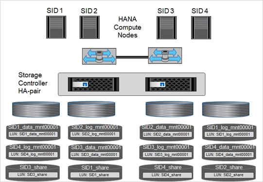
For each SAP HANA host, a data volume, a log volume, and a volume for /hana/shared are configured. Table 10 lists an example configuration with four SAP HANA scale-up systems.
Table 10. Volume Configuration for SAP HANA Scale-up Systems
| Aggregate 1 at |
Aggregate 2 at |
Aggregate 1 at |
Aggregate 2 at |
|
| Data, log, and shared volumes for system SID1 |
Data volume: SID1_data_mnt00001 |
Shared volume: SID1_shared |
– |
Log volume: SID1_log_mnt00001 |
| Data, log, and shared volumes for system SID2 |
– |
Log volume: SID2_log_mnt00001 |
Data volume: SID2_data_mnt00001 |
Shared volume: SID2_shared |
| Data, log, and shared volumes for system SID3 |
Shared volume: |
Data volume: SID3_data_mnt00001 |
Log volume: SID3_log_mnt00001 |
– |
| Data, log, and shared volumes for system SID4 |
Log volume: SID4_log_mnt00001 |
– |
Shared volume: |
Data volume: SID4_data_mnt00001 |
Table 11 lists an example mount point configuration for a scale-up system.
Table 11. Mount Points for Scale-up Systems
| LUN |
Mount Point at HANA Host |
Note |
| /hana/data/SID1/mnt00001 |
Mounted using /etc/fstab entry |
|
| SID1_log_mnt00001 |
/hana/log/SID1/mnt00001 |
Mounted using /etc/fstab entry |
| SID1_shared |
/hana/shared/SID1 |
Mounted using /etc/fstab entry |
Configuration Example for an SAP HANA Scale-up System
The following examples show an SAP HANA database with SID=FCS and a server RAM size of 1TB. For different server RAM sizes, the required volume sizes are different.
For a detailed description of the capacity requirements for SAP HANA, see the SAP HANA Storage Requirements white paper.
Create Volumes and Adjust Volume Options
To create a data, log, and shared volume and adjust the volume options, run the following commands:
volume create -vserver hana-svm -volume FCS_data_mnt00001 -aggregate aggr1_1 -size 1250GB -state online -snapshot-policy none -percent-snapshot-space 0 -space-guarantee none
volume create -vserver hana-svm -volume FCS_log_mnt00001 -aggregate aggr1_2 -size 700GB -state online -snapshot-policy none -percent-snapshot-space 0 -space-guarantee none
volume create -vserver hana-svm -volume FCS_shared -aggregate aggr2_1 -size 1250GB -state online -snapshot-policy none -percent-snapshot-space 0 -space-guarantee none
vol modify -vserver hana-svm -volume FCS* -snapdir-access false
Create the LUNs
To create a data, log and shared LUNS run the following commands:
lun create -vserver hana-svm -volume FCS_data_mnt00001 -lun FCS_data_mnt00001 -size 1TB -ostype Linux -space-reserve disabled
lun create -vserver hana-svm -volume FCS_log_mnt00001 -lun FCS_log_mnt00001 -size 512G -ostype Linux -space-reserve disabled
lun create -vserver hana-svm -volume FCS_shared -lun FCS_shared -size 1TB -ostype Linux -space-reserve disabled
To create a map the LUNs to the host server-01, run the following commands:
lun map -vserver hana-svm -volume FCS_data_mnt00001 -lun FCS_data_mnt00001 -igroup server-01
lun map -vserver hana-svm -volume FCS_log_mnt00001 -lun FCS_log_mnt00001 -igroup server-01
lun map -vserver hana-svm -volume FCS_shared -lun FCS_shared -size 1TB -igroup server-01
Update the Load-Sharing Mirror Relation
To update the load-sharing mirror relation, run the following command:
snapmirror update-ls-set -source-path hana-svm:hana_rootvol
Before setting up the host, NetApp SAN host utilities must be downloaded from the NetApp Support site and installed on the HANA servers. The host utility documentation includes information about additional software that must be installed depending on the FCP HBA used.
The documentation also contains information on multipath configurations that are specific to the Linux version used. This document covers the required configuration steps for SLES 12 SP1 or higher and RHEL 7.2 or later, as described in the Linux Host Utilities 7.1 Installation and Setup Guide.
Configure Multipathing
![]() Steps 1 through 6 must be executed on all worker and standby hosts in an SAP HANA scale-out configuration.
Steps 1 through 6 must be executed on all worker and standby hosts in an SAP HANA scale-out configuration.
To configure multipathing, follow these steps:
1. Run the Linux rescan-scsi-bus.sh -a command on each server to discover new LUNs.
2. Run the sanlun lun show command and verify that all required LUNs are visible. The following example shows the sanlun lun show command output for scale-up HANA system with one data LUN, one LOG LUN, and a LUN for /hana/shared. The output shows the LUNs and the corresponding device files, such as LUN FCS_data_mnt00001 and the device file /dev/sdag Each LUN has eight FC paths from the host to the storage controllers.
controller(7mode/E-Series)/ device host lun
vserver(cDOT/FlashRay) lun-pathname filename adapter protocol size product
-------------------------------------------------------------------------------------------------------------------------
controller(7mode/E-Series)/ device host lun
vserver(cDOT/FlashRay) lun-pathname filename adapter protocol size product
-------------------------------------------------------------------------------------------------------------------------
hana /vol/FCS_shared_01/FCS_shared_01 /dev/sdae host8 FCP 1.2t cDOT
hana /vol/FCS_shared_01/FCS_shared_01 /dev/sdad host8 FCP 1.2t cDOT
hana /vol/FCS_shared_01/FCS_shared_01 /dev/sdac host8 FCP 1.2t cDOT
hana /vol/FCS_shared_01/FCS_shared_01 /dev/sdab host8 FCP 1.2t cDOT
hana /vol/FCS_shared_01/FCS_shared_01 /dev/sdaa host7 FCP 1.2t cDOT
hana /vol/FCS_shared_01/FCS_shared_01 /dev/sdz host7 FCP 1.2t cDOT
hana /vol/FCS_shared_01/FCS_shared_01 /dev/sdy host7 FCP 1.2t cDOT
hana /vol/FCS_shared_01/FCS_shared_01 /dev/sdx host7 FCP 1.2t cDOT
hana /vol/FCS_data_mnt00001/FCS_data_mnt00001 /dev/sdw host8 FCP 1.2t cDOT
hana /vol/FCS_log_mnt00001/FCS_log_mnt00001 /dev/sdv host8 FCP 512.0g cDOT
hana /vol/FCS_data_mnt00001/FCS_data_mnt00001 /dev/sdu host8 FCP 1.2t cDOT
hana /vol/FCS_log_mnt00001/FCS_log_mnt00001 /dev/sdt host8 FCP 512.0g cDOT
hana /vol/FCS_data_mnt00001/FCS_data_mnt00001 /dev/sds host8 FCP 1.2t cDOT
hana /vol/FCS_log_mnt00001/FCS_log_mnt00001 /dev/sdr host8 FCP 512.0g cDOT
hana /vol/FCS_data_mnt00001/FCS_data_mnt00001 /dev/sdq host8 FCP 1.2t cDOT
hana /vol/FCS_log_mnt00001/FCS_log_mnt00001 /dev/sdp host8 FCP 512.0g cDOT
infra-svm /vol/server_boot/server-01 /dev/sdo host8 FCP 100g cDOT
infra-svm /vol/server_boot/server-01 /dev/sdn host8 FCP 100g cDOT
hana /vol/FCS_data_mnt00001/FCS_data_mnt00001 /dev/sdm host7 FCP 1.2t cDOT
hana /vol/FCS_log_mnt00001/FCS_log_mnt00001 /dev/sdl host7 FCP 512.0g cDOT
hana /vol/FCS_data_mnt00001/FCS_data_mnt00001 /dev/sdk host7 FCP 1.2t cDOT
hana /vol/FCS_log_mnt00001/FCS_log_mnt00001 /dev/sdj host7 FCP 512.0g cDOT
hana /vol/FCS_data_mnt00001/FCS_data_mnt00001 /dev/sdi host7 FCP 1.2t cDOT
hana /vol/FCS_log_mnt00001/FCS_log_mnt00001 /dev/sdh host7 FCP 512.0g cDOT
hana /vol/FCS_data_mnt00001/FCS_data_mnt00001 /dev/sdg host7 FCP 1.2t cDOT
hana /vol/FCS_log_mnt00001/FCS_log_mnt00001 /dev/sdf host7 FCP 512.0g cDOT
infra-svm /vol/server_boot/server-01 /dev/sde host7 FCP 100g cDOT
infra-svm /vol/server_boot/server-01 /dev/sdd host7 FCP 100g cDOT
3. Run the multipath -ll command to get the worldwide identifiers (WWIDs) for the device file names:
![]() In this example, there are four LUNs.
In this example, there are four LUNs.
3600a0980383143752d5d506d48386b54 dm-0 NETAPP,LUN C-Mode
size=100G features='3 queue_if_no_path pg_init_retries 50' hwhandler='1 alua' wp=rw
|-+- policy='service-time 0' prio=50 status=active
| |- 7:0:0:0 sdd 8:48 active ready running
| `- 8:0:2:0 sdn 8:208 active ready running
`-+- policy='service-time 0' prio=10 status=enabled
|- 7:0:1:0 sde 8:64 active ready running
`- 8:0:3:0 sdo 8:224 active ready running
3600a0980383143752d5d506d48386b61 dm-7 NETAPP,LUN C-Mode
size=1.2T features='3 queue_if_no_path pg_init_retries 50' hwhandler='1 alua' wp=rw
|-+- policy='service-time 0' prio=50 status=active
| |- 7:0:4:2 sdx 65:112 active ready running
| |- 7:0:7:2 sdaa 65:160 active ready running
| |- 8:0:5:2 sdac 65:192 active ready running
| `- 8:0:7:2 sdae 65:224 active ready running
`-+- policy='service-time 0' prio=10 status=enabled
|- 7:0:5:2 sdy 65:128 active ready running
|- 7:0:6:2 sdz 65:144 active ready running
|- 8:0:4:2 sdab 65:176 active ready running
`- 8:0:6:2 sdad 65:208 active ready running
3600a098038314375463f506c79694171 dm-5 NETAPP,LUN C-Mode
size=512G features='3 queue_if_no_path pg_init_retries 50' hwhandler='1 alua' wp=rw
|-+- policy='service-time 0' prio=50 status=active
| |- 7:0:5:0 sdh 8:112 active ready running
| |- 7:0:6:0 sdj 8:144 active ready running
| |- 8:0:4:0 sdp 8:240 active ready running
| `- 8:0:6:0 sdt 65:48 active ready running
`-+- policy='service-time 0' prio=10 status=enabled
|- 7:0:4:0 sdf 8:80 active ready running
|- 7:0:7:0 sdl 8:176 active ready running
|- 8:0:5:0 sdr 65:16 active ready running
`- 8:0:7:0 sdv 65:80 active ready running
3600a0980383143752d5d506d48386b58 dm-6 NETAPP,LUN C-Mode
size=1.2T features='3 queue_if_no_path pg_init_retries 50' hwhandler='1 alua' wp=rw
|-+- policy='service-time 0' prio=50 status=active
| |- 7:0:4:1 sdg 8:96 active ready running
| |- 7:0:7:1 sdm 8:192 active ready running
| |- 8:0:5:1 sds 65:32 active ready running
| `- 8:0:7:1 sdw 65:96 active ready running
`-+- policy='service-time 0' prio=10 status=enabled
|- 7:0:5:1 sdi 8:128 active ready running
|- 7:0:6:1 sdk 8:160 active ready running
|- 8:0:4:1 sdq 65:0 active ready running
`- 8:0:6:1 sdu 65:64 active ready running
4. Edit the /etc/multipath.conf file and add the WWIDs and alias names.
server-01:/ # cat /etc/multipath.conf
multipath {
wwid 3600a0980383143752d5d506d48386b58
alias hana-svm-FCS_data_mnt00001
}
multipath {
wwid 3600a098038314375463f506c79694171
alias hana-svm-FCS_log_mnt00001
}
multipath {
wwid 3600a0980383143752d5d506d48386b61
alias hana-svm-FCS_shared
}
}
5. Run the multipath -r command to reload the device map.
6. Verify the configuration by running the multipath -ll command to list all the LUNs, alias names, and active and standby paths.
![]() The multipath device dm-0 is the boot LUN from the infra-svm.
The multipath device dm-0 is the boot LUN from the infra-svm.
server-01:~ # multipath -ll
3600a0980383143752d5d506d48386b54 dm-0 NETAPP,LUN C-Mode
size=100G features='3 queue_if_no_path pg_init_retries 50' hwhandler='1 alua' wp=rw
|-+- policy='service-time 0' prio=50 status=enabled
| |- 7:0:0:0 sdd 8:48 active ready running
| `- 8:0:2:0 sdn 8:208 active ready running
`-+- policy='service-time 0' prio=10 status=enabled
|- 7:0:1:0 sde 8:64 active ready running
`- 8:0:3:0 sdo 8:224 active ready running
hana-svm-FCS_log_mnt00001 (3600a098038314375463f506c79694171) dm-5 NETAPP,LUN C-Mode
size=512G features='3 queue_if_no_path pg_init_retries 50' hwhandler='1 alua' wp=rw
|-+- policy='service-time 0' prio=50 status=active
| |- 7:0:5:0 sdh 8:112 active ready running
| |- 7:0:6:0 sdj 8:144 active ready running
| |- 8:0:4:0 sdp 8:240 active ready running
| `- 8:0:6:0 sdt 65:48 active ready running
`-+- policy='service-time 0' prio=10 status=enabled
|- 7:0:4:0 sdf 8:80 active ready running
|- 7:0:7:0 sdl 8:176 active ready running
|- 8:0:5:0 sdr 65:16 active ready running
`- 8:0:7:0 sdv 65:80 active ready running
hana-svm-FCS_shared (3600a0980383143752d5d506d48386b61) dm-7 NETAPP,LUN C-Mode
size=1.2T features='3 queue_if_no_path pg_init_retries 50' hwhandler='1 alua' wp=rw
|-+- policy='service-time 0' prio=50 status=active
| |- 7:0:4:2 sdx 65:112 active ready running
| |- 7:0:7:2 sdaa 65:160 active ready running
| |- 8:0:5:2 sdac 65:192 active ready running
| `- 8:0:7:2 sdae 65:224 active ready running
`-+- policy='service-time 0' prio=10 status=enabled
|- 7:0:5:2 sdy 65:128 active ready running
|- 7:0:6:2 sdz 65:144 active ready running
|- 8:0:4:2 sdab 65:176 active ready running
`- 8:0:6:2 sdad 65:208 active ready running
hana-svm-FCS_data_mnt00001 (3600a0980383143752d5d506d48386b58) dm-6 NETAPP,LUN C-Mode
size=1.2T features='3 queue_if_no_path pg_init_retries 50' hwhandler='1 alua' wp=rw
|-+- policy='service-time 0' prio=50 status=active
| |- 7:0:4:1 sdg 8:96 active ready running
| |- 7:0:7:1 sdm 8:192 active ready running
| |- 8:0:5:1 sds 65:32 active ready running
| `- 8:0:7:1 sdw 65:96 active ready running
`-+- policy='service-time 0' prio=10 status=enabled
|- 7:0:5:1 sdi 8:128 active ready running
|- 7:0:6:1 sdk 8:160 active ready running
|- 8:0:4:1 sdq 65:0 active ready running
`- 8:0:6:1 sdu 65:64 active ready running
Create File Systems
To create the XFS file system on each LUN belonging to the HANA system, take the following actions:
server-01:/ # mkfs.xfs -f /dev/mapper/hana-svm-FCS_data_mnt00001
server-01:/ # mkfs.xfs -f /dev/mapper/hana-svm-FCS_log_mnt00001
server-01:/ # mkfs.xfs -f /dev/mapper/hana-svm-FCS_shared
Create Mount Points
To create the required mount-point directories, take one of the following actions:
mkdir -p /hana/data/FCS/mnt00001
mkdir -p /hana/log/FCS/mnt00001
mkdir -p /hana/shared
mkdir -p /usr/sap/FCS
chmod 777 -R /hana/log/FCS
chmod 777 -R /hana/data/FCS
chmod 777 -R /hana/shared
chmod 777 -R /usr/sap/FCS
Mount File Systems
To mount file systems during system boot using the /etc/fstab configuration file, follow these steps:
1. Add the required file systems to the /etc/fstab configuration file.
![]() The XFS file systems for the data and log LUNs must be mounted with the relatime and inode64 mount options.
The XFS file systems for the data and log LUNs must be mounted with the relatime and inode64 mount options.
server-01:/ # cat /etc/fstab
/dev/mapper/hana-svm-FCS_shared /hana/shared xfs defaults 0 0
/dev/mapper/hana-svm-FCS_log_mnt00001 /hana/log/FCS/mnt00001 xfs relatime,inode64 0 0
/dev/mapper/hana-svm-FCS_data_mnt00001 /hana/data/FCS/mnt00001 xfs relatime,inode64 0 0
2. Run mount –a to mount the file systems on the host.
Configure SAP HANA Scale-out Systems
Volume and LUN Configuration for SAP HANA Scale-out Systems
Figure 6 shows the volume configuration of a 4+1 scale-out SAP HANA system. The data volumes and log volumes of each SAP HANA host are distributed to different storage controllers. For example, the volume SID_data_mnt00001 is configured on controller A and the volume SID_log_mnt00001 is configured on controller B. One LUN is configured within each volume.
The /hana/shared volume must be accessible by all HANA hosts and is therefore exported by using NFS. Even though there are no specific performance KPIs for the /hana/shared file system, NetApp recommends using a 10Gb Ethernet connection.
![]() If only one storage controller of high availability pair is used for the SAP HANA system, data and log volumes can also be stored on the same storage controller.
If only one storage controller of high availability pair is used for the SAP HANA system, data and log volumes can also be stored on the same storage controller.
Figure 6. Volume Layout for SAP HANA Scale-out Systems
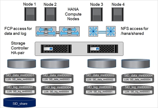
For each SAP HANA host, a data volume and a log volume are created. The /hana/shared volume is used by all hosts of the SAP HANA system. Table 12 lists an example configuration for a 4+1 scale-out SAP HANA system.
Table 12. Volume Configuration for SAP HANA Scale-out Systems
| Aggregate 1 at Controller A |
Aggregate 2 at Controller A |
Aggregate 1 at Controller B |
Aggregate 2 at Controller B |
|
| Data and log volumes for node 1 |
Data volume: SID_data_mnt00001 |
– |
Log volume: SID_log_mnt00001 |
– |
| Data and log volumes for node 2 |
Log volume: SID_log_mnt00002 |
– |
Data volume: SID_data_mnt00002 |
– |
| Data and log volumes for node 3 |
– |
Data volume: SID_data_mnt00003 |
– |
Log volume: SID_log_mnt00003 |
| Data and log volumes for node 4 |
– |
Log volume: SID_log_mnt00004 |
– |
Data volume: SID_data_mnt00004 |
| Shared volume for all hosts |
Shared volume: SID_shared |
– |
– |
– |
Table 13 lists the configuration and the mount points of a scale-out system with four active SAP HANA hosts.
Table 13. Mount Points for Scale-out Systems
| LUN or Volume |
Mount Point at SAP HANA Host |
Note |
| LUN: SID_data_mnt00001 |
/hana/data/SID/mnt00001 |
Mounted using storage connector |
| LUN: SID_log_mnt00001 |
/hana/log/SID/mnt00001 |
Mounted using storage connector |
| LUN: SID_data_mnt00002 |
/hana/data/SID/mnt00002 |
Mounted using storage connector |
| LUN: SID_log_mnt00002 |
/hana/log/SID/mnt00002 |
Mounted using storage connector |
| LUN: SID_data_mnt00003 |
/hana/data/SID/mnt00003 |
Mounted using storage connector |
| LUN: SID_log_mnt00003 |
/hana/log/SID/mnt00003 |
Mounted using storage connector |
| LUN: SID_data_mnt00004 |
/hana/data/SID/mnt00004 |
Mounted using storage connector |
| LUN: SID_log_mnt00004 |
/hana/log/SID/mnt00004 |
Mounted using storage connector |
| Volume: SID_shared |
/hana/shared |
Mounted at all hosts using NFS and /etc/fstab entry |
Configuration Example for SAP HANA Scale-out Systems
The following examples show a 4+1 SAP HANA scale-out database with SID=FLX and a server with a RAM size of 2TB. For different server RAM sizes, the required volume sizes are different.
For a detailed description of the capacity requirements for SAP HANA, see the SAP HANA Storage Requirements white paper.
Creating LUNs, Volumes, and Mapping LUNs to Initiator Groups
You can use NetApp ONTAP System Manager and CLI to create storage volumes and LUNs and map them to the servers.
NetApp offers an automated application wizard for SAP HANA within ONTAP System Manager, which simplifies the volume and LUN provisioning process significantly. It creates and configures the volumes and LUNs automatically according to NetApp best practices for SAP HANA.
Using the sanlun tool, run the following command to obtain the worldwide port names (WWPNs) of each SAP HANA host:
server-01:~ # sanlun fcp show adapter
/sbin/udevadm
/sbin/udevadm
host0 ...... WWPN:2100000e1e163700
host1 ...... WWPN:2100000e1e163701
![]() The sanlun tool is part of the NetApp Host Utilities and must be installed on each SAP HANA host. For more information, see section “Host Setup.”
The sanlun tool is part of the NetApp Host Utilities and must be installed on each SAP HANA host. For more information, see section “Host Setup.”
To configure a 4+1 scale-out HANA system with the SID FLX, follow these steps:
1. Start the Application Provisioning wizard for SAP HANA in System Manager and provide the required information. All initiators (WWPNs) from all hosts need to be added.
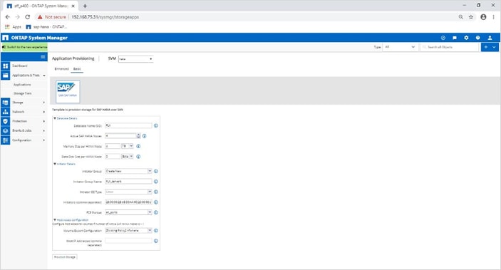
2. Confirm that storage is successfully provisioned.
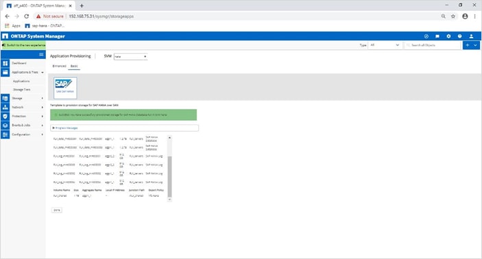
SAP HANA Storage Connector API
A storage connector is required in scale-out environments that have failover capabilities. In scale-out setups, SAP HANA provides high-availability functionality so that an SAP HANA database host can fail over to a standby host. In this case, the LUNs of the failed host is accessed and used by the standby host. The storage connector is used to make sure that a storage partition can be actively accessed by only one database host at a time.
In SAP HANA scale-out configurations with NetApp storage, the standard storage connector delivered by SAP is used. The “SAP HANA Fibre Channel Storage Connector Admin Guide” can be found as an attachment to SAP note 1900823.
Before setting up the host, NetApp SAN host utilities must be downloaded from the NetApp Support site and installed on the HANA servers. The host utility documentation includes information about additional software that must be installed depending on the FCP HBA used.
The documentation also contains information on multipath configurations that are specific to the Linux version used. This document covers the required configuration steps for SLES 12 SP1 or higher and RHEL 7.2 or later, as described in the Linux Host Utilities 7.1 Installation and Setup Guide.
Configure Multipathing
![]() Steps 1 through 6 must be executed on all worker and standby hosts in an SAP HANA scale-out configuration.
Steps 1 through 6 must be executed on all worker and standby hosts in an SAP HANA scale-out configuration.
To configure multipathing, follow these steps:
1. Run the Linux rescan-scsi-bus.sh -a command on each server to discover new LUNs.
2. Run the sanlun lun show command and verify that all required LUNs are visible. The following example shows the sanlun lun show command output for a 2+1 scale-out HANA system with two data LUNs and two log LUNs. The output shows the LUNs and the corresponding device files, such as LUN SS3_data_mnt00001 and the device file /dev/sdag Each LUN has eight FC paths from the host to the storage controllers.
server-01:~ # sanlun lun show
controller(7mode/E-Series)/ device host lun
vserver(cDOT/FlashRay) lun-pathname filename adapter protocol size product
-------------------------------------------------------------------------------------------------------------------------
hana-svm /vol/FLX_log_mnt00002/FLX_log_mnt00002 /dev/sdah host11 FCP 512.0g cDOT
hana-svm /vol/FLX_data_mnt00001/FLX_data_mnt00001 /dev/sdag host11 FCP 1.2t cDOT
hana-svm /vol/SS3_data_mnt00002/FLX_data_mnt00002 /dev/sdaf host11 FCP 1.2t cDOT
hana-svm /vol/FLX_log_mnt00002/FLX_log_mnt00002 /dev/sdae host11 FCP 512.0g cDOT
hana-svm /vol/FLX_data_mnt00001/FLX_data_mnt00001 /dev/sdad host11 FCP 1.2t cDOT
hana-svm /vol/FLX_data_mnt00002/FLX_data_mnt00002 /dev/sdac host11 FCP 1.2t cDOT
hana-svm /vol/FLX_log_mnt00002/FLX_log_mnt00002 /dev/sdab host11 FCP 512.0g cDOT
hana-svm /vol/FLX_data_mnt00001/FLX_data_mnt00001 /dev/sdaa host11 FCP 1.2t cDOT
hana-svm /vol/FLX_data_mnt00002/FLX_data_mnt00002 /dev/sdz host11 FCP 1.2t cDOT
hana-svm /vol/FLX_log_mnt00002/FLX_log_mnt00002 /dev/sdy host11 FCP 512.0g cDOT
hana-svm /vol/FLX_data_mnt00001/FLX_data_mnt00001 /dev/sdx host11 FCP 1.2t cDOT
hana-svm /vol/FLX_data_mnt00002/FLX_data_mnt00002 /dev/sdw host11 FCP 1.2t cDOT
hana-svm /vol/FLX_log_mnt00001/FLX_log_mnt00001 /dev/sdv host11 FCP 512.0g cDOT
hana-svm /vol/FLX_log_mnt00001/FLX_log_mnt00001 /dev/sdu host11 FCP 512.0g cDOT
hana-svm /vol/FLX_log_mnt00001/FLX_log_mnt00001 /dev/sdt host11 FCP 512.0g cDOT
hana-svm /vol/FLX_log_mnt00001/FLX_log_mnt00001 /dev/sds host11 FCP 512.0g cDOT
hana-svm /vol/FLX_log_mnt00002/FLX_log_mnt00002 /dev/sdr host10 FCP 512.0g cDOT
hana-svm /vol/FLX_data_mnt00001/FLX_data_mnt00001 /dev/sdq host10 FCP 1.2t cDOT
hana-svm /vol/FLX_data_mnt00002/FLX_data_mnt00002 /dev/sdp host10 FCP 1.2t cDOT
hana-svm /vol/FLX_log_mnt00002/FLX_log_mnt00002 /dev/sdo host10 FCP 512.0g cDOT
hana-svm /vol/FLX_data_mnt00001/FLX_data_mnt00001 /dev/sdn host10 FCP 1.2t cDOT
hana-svm /vol/FLX_data_mnt00002/FLX_data_mnt00002 /dev/sdm host10 FCP 1.2t cDOT
hana-svm /vol/FLX_log_mnt00002/FLX_log_mnt00002 /dev/sdl host10 FCP 512.0g cDOT
hana-svm /vol/FLX_data_mnt00001/FLX_data_mnt00001 /dev/sdk host10 FCP 1.2t cDOT
hana-svm /vol/FLX_data_mnt00002/FLX_data_mnt00002 /dev/sdj host10 FCP 1.2t cDOT
hana-svm /vol/FLX_log_mnt00002/FLX_log_mnt00002 /dev/sdi host10 FCP 512.0g cDOT
hana-svm /vol/FLX_data_mnt00001/FLX_data_mnt00001 /dev/sdh host10 FCP 1.2t cDOT
hana-svm /vol/FLX_data_mnt00002/FLX_data_mnt00002 /dev/sdg host10 FCP 1.2t cDOT
hana-svm /vol/FLX_log_mnt00001/FLX_log_mnt00001 /dev/sdf host10 FCP 512.0g cDOT
hana-svm /vol/FLX_log_mnt00001/FLX_log_mnt00001 /dev/sde host10 FCP 512.0g cDOT
hana-svm /vol/FLX_log_mnt00001/FLX_log_mnt00001 /dev/sdd host10 FCP 512.0g cDOT
hana-svm /vol/FLX_log_mnt00001/FLX_log_mnt00001 /dev/sdc host10 FCP 512.0g cDOT
hana-svm /vol/FLX_log_mnt00004/FLX_log_mnt00004 /dev/sdbh host11 FCP 512.0g cDOT
hana-svm /vol/FLX_data_mnt00003/FLX_data_mnt00003 /dev/sdbg host11 FCP 1.2t cDOT
hana-svm /vol/FLX_data_mnt00004/FLX_data_mnt00004 /dev/sdbf host11 FCP 1.2t cDOT
hana-svm /vol/FLX_log_mnt00004/FLX_log_mnt00004 /dev/sdbe host11 FCP 512.0g cDOT
hana-svm /vol/FLX_data_mnt00003/FLX_data_mnt00003 /dev/sdbd host11 FCP 1.2t cDOT
hana-svm /vol/FLX_data_mnt00004/FLX_data_mnt00004 /dev/sdbc host11 FCP 1.2t cDOT
hana-svm /vol/FLX_log_mnt00003/FLX_log_mnt00003 /dev/sdbb host11 FCP 512.0g cDOT
hana-svm /vol/FLX_data_mnt00003/FLX_data_mnt00003 /dev/sdba host11 FCP 1.2t cDOT
hana-svm /vol/FLX_data_mnt00004/FLX_data_mnt00004 /dev/sdbz host11 FCP 1.2t cDOT
hana-svm /vol/FLX_log_mnt00004/FLX_log_mnt00004 /dev/sdby host11 FCP 512.0g cDOT
hana-svm /vol/FLX_data_mnt00003/FLX_data_mnt00003 /dev/sdbx host11 FCP 1.2t cDOT
hana-svm /vol/FLX_data_mnt00004/FLX_data_mnt00004 /dev/sdbw host11 FCP 1.2t cDOT
hana-svm /vol/FLX_log_mnt00003/FLX_log_mnt00003 /dev/sdbv host11 FCP 512.0g cDOT
hana-svm /vol/FLX_log_mnt00003/FLX_log_mnt00003 /dev/sdbu host11 FCP 512.0g cDOT
hana-svm /vol/FLX_log_mnt00003/FLX_log_mnt00003 /dev/sdbt host11 FCP 512.0g cDOT
hana-svm /vol/FLX_log_mnt00003/FLX_log_mnt00003 /dev/sdbs host11 FCP 512.0g cDOT
hana-svm /vol/FLX_log_mnt00004/FLX_log_mnt00004 /dev/sdbr host10 FCP 512.0g cDOT
hana-svm /vol/FLX_data_mnt00003/FLX_data_mnt00003 /dev/sdbq host10 FCP 1.2t cDOT
hana-svm /vol/FLX_data_mnt00004/FLX_data_mnt00004 /dev/sdbp host10 FCP 1.2t cDOT
hana-svm /vol/FLX_log_mnt00004/FLX_log_mnt00004 /dev/sdbo host10 FCP 512.0g cDOT
hana-svm /vol/FLX_data_mnt00003/FLX_data_mnt00003 /dev/sdbn host10 FCP 1.2t cDOT
hana-svm /vol/FLX_data_mnt00004/FLX_data_mnt00004 /dev/sdbm host10 FCP 1.2t cDOT
hana-svm /vol/FLX_log_mnt00004/FLX_log_mnt00004 /dev/sdbl host10 FCP 512.0g cDOT
hana-svm /vol/FLX_data_mnt00003/FLX_data_mnt00003 /dev/sdbk host10 FCP 1.2t cDOT
hana-svm /vol/FLX_data_mnt00004/FLX_data_mnt00004 /dev/sdbj host10 FCP 1.2t cDOT
hana-svm /vol/FLX_log_mnt00004/FLX_log_mnt00004 /dev/sdbi host10 FCP 512.0g cDOT
hana-svm /vol/FLX_data_mnt00003/FLX_data_mnt00003 /dev/sdch host10 FCP 1.2t cDOT
hana-svm /vol/FLX_data_mnt00004/FLX_data_mnt00004 /dev/sdcg host10 FCP 1.2t cDOT
hana-svm /vol/FLX_log_mnt00003/FLX_log_mnt00003 /dev/sdcf host10 FCP 512.0g cDOT
hana-svm /vol/FLX_log_mnt00003/FLX_log_mnt00003 /dev/sdce host10 FCP 512.0g cDOT
hana-svm /vol/FLX_log_mnt00003/FLX_log_mnt00003 /dev/sdcd host10 FCP 512.0g cDOT
hana-svm /vol/FLX_log_mnt00003/FLX_log_mnt00003 /dev/sdcc host10 FCP 512.0g cDOT
3. Run the multipath -r command to get the worldwide identifiers (WWIDs) for the device file names:
![]() In this example, result is truncated to show four LUNs.
In this example, result is truncated to show four LUNs.
server-01:~ # multipath -r
create: 3600a098038304436375d4d442d753878 undef NETAPP,LUN C-Mode
size=512G features='3 pg_init_retries 50 queue_if_no_path' hwhandler='0' wp=undef
|-+- policy='service-time 0' prio=50 status=undef
| |- 10:0:1:0 sdd 8:48 undef ready running
| |- 10:0:3:0 sdf 8:80 undef ready running
| |- 11:0:0:0 sds 65:32 undef ready running
| `- 11:0:2:0 sdu 65:64 undef ready running
`-+- policy='service-time 0' prio=10 status=undef
|- 10:0:0:0 sdc 8:32 undef ready running
|- 10:0:2:0 sde 8:64 undef ready running
|- 11:0:1:0 sdt 65:48 undef ready running
`- 11:0:3:0 sdv 65:80 undef ready running
create: 3600a098038304436375d4d442d753879 undef NETAPP,LUN C-Mode
size=1.2T features='3 pg_init_retries 50 queue_if_no_path' hwhandler='0' wp=undef
|-+- policy='service-time 0' prio=50 status=undef
| |- 10:0:1:1 sdj 8:144 undef ready running
| |- 10:0:3:1 sdp 8:240 undef ready running
| |- 11:0:0:1 sdw 65:96 undef ready running
| `- 11:0:2:1 sdac 65:192 undef ready running
`-+- policy='service-time 0' prio=10 status=undef
|- 10:0:0:1 sdg 8:96 undef ready running
|- 10:0:2:1 sdm 8:192 undef ready running
|- 11:0:1:1 sdz 65:144 undef ready running
`- 11:0:3:1 sdaf 65:240 undef ready running
create: 3600a098038304436392b4d442d6f534f undef NETAPP,LUN C-Mode
size=1.2T features='3 pg_init_retries 50 queue_if_no_path' hwhandler='0' wp=undef
|-+- policy='service-time 0' prio=50 status=undef
| |- 10:0:0:2 sdh 8:112 undef ready running
| |- 10:0:2:2 sdn 8:208 undef ready running
| |- 11:0:1:2 sdaa 65:160 undef ready running
| `- 11:0:3:2 sdag 66:0 undef ready running
`-+- policy='service-time 0' prio=10 status=undef
|- 10:0:1:2 sdk 8:160 undef ready running
|- 10:0:3:2 sdq 65:0 undef ready running
|- 11:0:0:2 sdx 65:112 undef ready running
`- 11:0:2:2 sdad 65:208 undef ready running
create: 3600a098038304436392b4d442d6f5350 undef NETAPP,LUN C-Mode
size=512G features='3 pg_init_retries 50 queue_if_no_path' hwhandler='0' wp=undef
|-+- policy='service-time 0' prio=50 status=undef
| |- 10:0:0:3 sdi 8:128 undef ready running
| |- 10:0:2:3 sdo 8:224 undef ready running
| |- 11:0:1:3 sdab 65:176 undef ready running
| `- 11:0:3:3 sdah 66:16 undef ready running
`-+- policy='service-time 0' prio=10 status=undef
|- 10:0:1:3 sdl 8:176 undef ready running
|- 10:0:3:3 sdr 65:16 undef ready running
|- 11:0:0:3 sdy 65:128 undef ready running
`- 11:0:2:3 sdae 65:224 undef ready running
…
4. Edit the /etc/multipath.conf file and add the WWIDs and alias names.
![]() The example output shows the content of the /etc/multipath.conf file, which includes alias names for the four LUNs of a 2+1 scale-out system. If there is no multipath.conf file available, you can create one by running the following command: multipath -T > /etc/multipath.conf.
The example output shows the content of the /etc/multipath.conf file, which includes alias names for the four LUNs of a 2+1 scale-out system. If there is no multipath.conf file available, you can create one by running the following command: multipath -T > /etc/multipath.conf.
server-01:/ # cat /etc/multipath.conf
multipaths {
multipath {
wwid 3600a098038304436392b4d442d6f534f
alias hana-svm-FLX_data_mnt00001
}
multipath {
wwid 3600a098038304436375d4d442d753879
alias hana-svm-FLX_data_mnt00002
}
multipath {
wwid 3600a098038304436375d4d442d753878
alias hana-svm-FLX_log_mnt00001
}
multipath {
wwid 3600a098038304436392b4d442d6f5350
alias hana-svm-FLX_log_mnt00002
}
multipath {
wwid 3600a098038304436392b4d442d6f5352
alias hana-svm-FLX_data_mnt00003
}
multipath {
wwid 3600a098038304436375d4d442d753881
alias hana-svm-FLX_data_mnt00004
}
multipath {
wwid 3600a098038304436375d4d442d753880
alias hana-svm-FLX_log_mnt00003
}
multipath {
wwid 3600a098038304436392b4d442d6f5351
alias hana-svm-FLX_log_mnt00004
}
}
5. Run the multipath -r command to reload the device map.
6. Verify the configuration by running the multipath -ll command to list all the LUNs, alias names, and active and standby paths.
![]() The following example output shows the output of a 4+1 scale-out HANA system with 4 data and 4 log LUNs.
The following example output shows the output of a 4+1 scale-out HANA system with 4 data and 4 log LUNs.
server-01:~ # multipath -ll
hana-svm-FLX_data_mnt00002 (3600a098038304436375d4d442d753879) dm-1 NETAPP,LUN C-Mode
size=1.2T features='4 queue_if_no_path pg_init_retries 50 retain_attached_hw_handler' hwhandler='1 alua' wp=rw
|-+- policy='service-time 0' prio=50 status=enabled
| |- 10:0:1:1 sdj 8:144 active ready running
| |- 10:0:3:1 sdp 8:240 active ready running
| |- 11:0:0:1 sdw 65:96 active ready running
| `- 11:0:2:1 sdac 65:192 active ready running
`-+- policy='service-time 0' prio=10 status=enabled
|- 10:0:0:1 sdg 8:96 active ready running
|- 10:0:2:1 sdm 8:192 active ready running
|- 11:0:1:1 sdz 65:144 active ready running
`- 11:0:3:1 sdaf 65:240 active ready running
hana-svm-FLX_data_mnt00001 (3600a098038304436392b4d442d6f534f) dm-2 NETAPP,LUN C-Mode
size=1.2T features='4 queue_if_no_path pg_init_retries 50 retain_attached_hw_handler' hwhandler='1 alua' wp=rw
|-+- policy='service-time 0' prio=50 status=enabled
| |- 10:0:0:2 sdh 8:112 active ready running
| |- 10:0:2:2 sdn 8:208 active ready running
| |- 11:0:1:2 sdaa 65:160 active ready running
| `- 11:0:3:2 sdag 66:0 active ready running
`-+- policy='service-time 0' prio=10 status=enabled
|- 10:0:1:2 sdk 8:160 active ready running
|- 10:0:3:2 sdq 65:0 active ready running
|- 11:0:0:2 sdx 65:112 active ready running
`- 11:0:2:2 sdad 65:208 active ready running
hana-svm-FLX_log_mnt00002 (3600a098038304436392b4d442d6f5350) dm-3 NETAPP,LUN C-Mode
size=512G features='4 queue_if_no_path pg_init_retries 50 retain_attached_hw_handler' hwhandler='1 alua' wp=rw
|-+- policy='service-time 0' prio=50 status=enabled
| |- 10:0:0:3 sdi 8:128 active ready running
| |- 10:0:2:3 sdo 8:224 active ready running
| |- 11:0:1:3 sdab 65:176 active ready running
| `- 11:0:3:3 sdah 66:16 active ready running
`-+- policy='service-time 0' prio=10 status=enabled
|- 10:0:1:3 sdl 8:176 active ready running
|- 10:0:3:3 sdr 65:16 active ready running
|- 11:0:0:3 sdy 65:128 active ready running
`- 11:0:2:3 sdae 65:224 active ready running
hana-svm-FLX_log_mnt00001 (3600a098038304436375d4d442d753878) dm-0 NETAPP,LUN C-Mode
size=512G features='4 queue_if_no_path pg_init_retries 50 retain_attached_hw_handler' hwhandler='1 alua' wp=rw
|-+- policy='service-time 0' prio=50 status=enabled
| |- 10:0:1:0 sdd 8:48 active ready running
| |- 10:0:3:0 sdf 8:80 active ready running
| |- 11:0:0:0 sds 65:32 active ready running
| `- 11:0:2:0 sdu 65:64 active ready running
`-+- policy='service-time 0' prio=10 status=enabled
|- 10:0:0:0 sdc 8:32 active ready running
|- 10:0:2:0 sde 8:64 active ready running
|- 11:0:1:0 sdt 65:48 active ready running
`- 11:0:3:0 sdv 65:80 active ready running
…
Create File Systems
To create the XFS file system on each LUN belonging to the HANA system, take one of the following actions:
![]() For a scale-out system, create the XFS file system on all data and log LUNs.
For a scale-out system, create the XFS file system on all data and log LUNs.
server-01:~ # mkfs.xfs /dev/mapper/hana-svm-FLX_log_mnt00001
server-01:~ # mkfs.xfs /dev/mapper/hana-svm-FLX_log_mnt00002
server-01:~ # mkfs.xfs /dev/mapper/hana-svm-FLX_log_mnt00003
server-01:~ # mkfs.xfs /dev/mapper/hana-svm-FLX_log_mnt00004
server-01:~ # mkfs.xfs /dev/mapper/hana-svm-FLX_data_mnt00001
server-01:~ # mkfs.xfs /dev/mapper/hana-svm-FLX_data_mnt00002
server-01:~ # mkfs.xfs /dev/mapper/hana-svm-FLX_data_mnt00003
server-01:~ # mkfs.xfs /dev/mapper/hana-svm-FLX_data_mnt00004
Create Mount Points
Set permissions and create mount points on all worker and standby hosts.
![]() The example commands show a 4+1 scale-out HANA system.
The example commands show a 4+1 scale-out HANA system.
server-01:/ # mkdir -p /hana/data/FLX/mnt00001
server-01:/ # mkdir -p /hana/log/FLXmnt00001
server-01:/ # mkdir -p /hana/data/FLX/mnt00002
server-01:/ # mkdir -p /hana/log/FLX/mnt00002
server-01:/ # mkdir -p /hana/data/FLX/mnt00003
server-01:/ # mkdir -p /hana/log/FLXmnt00003
server-01:/ # mkdir -p /hana/data/FLX/mnt00004
server-01:/ # mkdir -p /hana/log/FLX/mnt00004
server-01:/ # mkdir -p /hana/shared
server-01:/ # chmod 777 -R /hana/log/FLX
server-01:/ # chmod 777 -R /hana/data/FLX
server-01:/ # chmod 777 /hana/shared
Mount File Systems
To mount file systems during system boot using the /etc/fstab configuration file, follow these steps:
1. Add the /hana/shared file system to the /etc/fstab configuration file of each host.
![]() All the data and log file systems are mounted through the SAP HANA storage connector.
All the data and log file systems are mounted through the SAP HANA storage connector.
server-01:/ # cat /etc/fstab
<storage-ip>:/hana_shared /hana/shared nfs rw,vers=3,hard,timeo=600,intr,noatime,nolock 0 0
2. To mount the file systems, run the mount –a command at each host.
3. A sample global.ini file from the installed Scale-out SAP HANA system is shown below:
[communication]
listeninterface = .global
[persistence]
basepath_datavolumes = /hana/data/FLX
basepath_logvolumes = /hana/log/FLX
[storage]
ha_provider = hdb_ha.fcClient
partition_*_*__prtype = 5
partition_*_data__mountoptions = -o relatime,inode64
partition_*_log__mountoptions = -o relatime,inode64,nobarrier
partition_1_data__wwid = hana-svm-FLX_data_mnt00001
partition_1_log__wwid = hana-svm-FLX_log_mnt00001
partition_2_data__wwid = hana-svm-FLX_data_mnt00002
partition_2_log__wwid = hana-svm-FLX_log_mnt00002
partition_3_data__wwid = hana-svm-FLX_data_mnt00003
partition_3_log__wwid = hana-svm-FLX_log_mnt00003
partition_4_data__wwid = hana-svm-FLX_data_mnt00004
partition_4_log__wwid = hana-svm-FLX_log_mnt00004
[system_information]
usage = custom
[trace]
ha_fcclient = info
For information about the SAP HANA installation, please use the official SAP documentation, which describes the installation process with and without the SAP unified installer.
![]() Read the SAP Notes before you start the installation (see Important SAP Notes) These SAP Notes contain the latest information about the installation, as well as corrections to the installation documentation.
Read the SAP Notes before you start the installation (see Important SAP Notes) These SAP Notes contain the latest information about the installation, as well as corrections to the installation documentation.
SAP HANA Server Installation Guide
All other SAP installation and administration documentation is available here: http://service.sap.com/instguides.
Read the following SAP Notes before you start the installation. These SAP Notes contain the latest information about the installation, as well as corrections to the installation documentation.
The latest SAP Notes can be found here: https://service.sap.com/notes.
SAP Note 1514967 - SAP HANA: Central Note
SAP Note 1523337 - SAP HANA Database: Central Note
SAP Note 2000003 - FAQ: SAP HANA
SAP Note 1730999![]() - Configuration changes in SAP HANA appliance
- Configuration changes in SAP HANA appliance
SAP Note 1514966![]() - SAP HANA 1.0: Sizing SAP In-Memory Database
- SAP HANA 1.0: Sizing SAP In-Memory Database
SAP Note 1743225![]() - SAP HANA: Potential failure of connections with scale out nodes
- SAP HANA: Potential failure of connections with scale out nodes
SAP Note 1681092 - Support for multiple SAP HANA databases on a single SAP HANA appliance
SAP Note 1514966 - SAP HANA: Sizing SAP HANA Database
SAP Note 1637145 - SAP BW on HANA: Sizing SAP HANA Database
SAP Note 1793345 - Sizing for Suite on HANA
SAP Note 2235581 - SAP HANA: Supported Operating Systems
2578899 - SUSE Linux Enterprise Server 15: Installation Note
SAP Note 2009879 - SAP HANA Guidelines for Red Hat Enterprise Linux (RHEL)
SAP Note 1731000![]() - Non-recommended configuration changes
- Non-recommended configuration changes
SAP Note 2382421 - Optimizing the Network Configuration on HANA- and OS-Level
SAP Note 1829651![]() - Time zone settings in SAP HANA scale out landscapes
- Time zone settings in SAP HANA scale out landscapes
SAP Note 1658845![]() - SAP HANA DB hardware check
- SAP HANA DB hardware check
SAP Note 1637145![]() - SAP BW on SAP HANA: Sizing SAP In-Memory Database
- SAP BW on SAP HANA: Sizing SAP In-Memory Database
SAP Note 1661202![]() - Support for multiple applications on SAP HANA
- Support for multiple applications on SAP HANA
SAP Note 1681092![]() - Support for multiple SAP HANA databases one HANA aka Multi SID
- Support for multiple SAP HANA databases one HANA aka Multi SID
SAP Note 1577128![]() - Supported clients for SAP HANA 1.0
- Supported clients for SAP HANA 1.0
SAP Note 1808450![]() - Homogenous system landscape for on BW-HANA
- Homogenous system landscape for on BW-HANA
SAP Note 1976729 - Application Component Hierarchy for SAP HANA
SAP Note 1927949 - Standard Behavior for SAP Logon Tickets
SAP Note 1577128 - Supported clients for SAP HANA
SAP Note 2186744 - FAQ: SAP HANA Parameters
SAP Note 2267798 - Configuration of the SAP HANA Database during Installation Using hdbparam
SAP Note 2156526 - Parameter constraint validation on section indices does not work correctly with hdbparam
SAP Note 2399079 - Elimination of hdbparam in HANA 2
SAP Note 1730928![]() - Using external software in an SAP HANA appliance
- Using external software in an SAP HANA appliance
SAP Note 1730929![]() - Using external tools in an SAP HANA appliance
- Using external tools in an SAP HANA appliance
SAP Note 1730930![]() - Using antivirus software in an SAP HANA appliance
- Using antivirus software in an SAP HANA appliance
SAP Note 1730932![]() - Using backup tools with Backint for SAP HANA
- Using backup tools with Backint for SAP HANA
TR-4436-SAP HANA on NetApp AFF Systems with FCP
TR-4614-SAP HANA Backup and Recovery with SnapCenter
TR-4646-SAP HANA Disaster Recovery with Storage Replication
High-Availability Configuration for Scale-out Systems
Before beginning the installation, create a global.ini file to enable use of the SAP storage connector during the installation process. The SAP storage connector mounts the required file systems at the worker hosts during the installation process. The global.ini file must be available in a file system that is accessible from all hosts, such as the /hana/shared file system.
Before installing SAP HANA software on a scale-out system, the following steps must be completed:
1. Add the following mount options for the data LUNs and the log LUNs to the global.ini file:
a. relatime and inode64 for the data file system
b. relatime and inode64 for the log file system
2. Add the WWIDs of the data and log partitions. The WWIDs must match the alias names configured in the /etc/multipath.conf file.
3. Prepare global.ini file for the installation of a Scale-out SAP HANA system. Example is shown below:
[communication]
listeninterface = .global
[persistence]
basepath_datavolumes = /hana/data/FLX
basepath_logvolumes = /hana/log/FLX
[storage]
ha_provider = hdb_ha.fcClient
partition_*_*__prtype = 5
partition_*_data__mountoptions = -o relatime,inode64
partition_*_log__mountoptions = -o relatime,inode64
partition_1_data__wwid = hana-svm-FLX_data_mnt00001
partition_1_log__wwid = hana-svm-FLX_log_mnt00001
partition_2_data__wwid = hana-svm-FLX_data_mnt00002
partition_2_log__wwid = hana-svm-FLX_log_mnt00002
partition_3_data__wwid = hana-svm-FLX_data_mnt00003
partition_3_log__wwid = hana-svm-FLX_log_mnt00003
partition_4_data__wwid = hana-svm-FLX_data_mnt00004
partition_4_log__wwid = hana-svm-FLX_log_mnt00004
[system_information]
usage = custom
[trace]
ha_fcclient = info
4. Using the SAP hdblcm installation tool, start the installation by running the following command at one of the worker hosts. Use the addhosts option to add the further worker and the standby hosts
![]() The directory where the prepared global.ini file is stored is included with the storage_cfg CLI option (--storage_cfg=/hana/shared). Depending on the OS version being used, it might be necessary to install phyton 2.7 before installing the SAP HANA database. For example, zypper in python for SuSe SLES 15SP1.
The directory where the prepared global.ini file is stored is included with the storage_cfg CLI option (--storage_cfg=/hana/shared). Depending on the OS version being used, it might be necessary to install phyton 2.7 before installing the SAP HANA database. For example, zypper in python for SuSe SLES 15SP1.
A default SAP HANA instance uses only one data volume per SAP HANA service. Due to the max file size limitation of the file system, NetApp recommends limiting max data volume size.
To automatically limit the max data volume size, set the following parameter in the global.ini within section (persistence):
datavolume_striping = true
datavolume_striping_size_gb = 8000
This creates a new data volume when the limit of 8000GB is reached.
SAP Note 240005 question 15 provides more information: https://launchpad.support.sap.com/#/notes/2400005
Cisco Intersight is an intelligent Software-as-a-Service (SaaS) platform for IT staff to manage and get support for their Intersight-connected environment when and where they need it. It simplifies the infrastructure management and provides proactive support for the FlexPod environment.
Cisco Intersight Assist helps to add endpoint devices Cisco UCS Domain, Hypervisors (in case of virtual implementations) and more to Cisco Intersight and provides the connection mechanism to claim the device in Cisco Intersight.
Cisco Intersight Assist is available as part of the Cisco Intersight Virtual Appliance, which is distributed as a deployable virtual machine contained within an Open Virtual Appliance (OVA) file format. Install the appliance on an ESXi server on-premise. For more information see the Cisco Intersight Assist Getting Started Guide.
The Cisco Intersight Help Center provides an overview and information on how to get started with Cisco Intersight. The Help Center is available from https://intersight.com/help/home.
Requirements
The following prerequisites are necessary to setup access to Cisco Intersight and to connect the core FlexPod components to Intersight:
● A valid Cisco Intersight account. Navigate to https://intersight.com to create an account and follow the account creation instructions. The account creation requires at least one device to be registered in Intersight including its Device ID and Claim ID information.
● Valid Advanced or Premier License for Cisco Intersight.
● Cisco UCS Fabric Interconnects must be able to do a DNS lookup to access Cisco Intersight.
● External endpoints registration messages to be routed to Cisco Intersight.
● Calls from non-registered endpoints (or other infrastructure devices) to be routed to Cisco Intersight.
Table 14. Connectivity Requirements (direct or through HTTP proxy)
| Name |
Service |
Protocol |
Port |
Target Host |
| expe.example.com |
Smart Licensing |
TCP/UDP |
443 |
tools.cisco.com |
| expe.example.com |
Software download |
TCP/UDP |
443 |
api.cisco.com |
| expe.example.com |
Intersight Cloud Services |
TCP/UDP |
443 |
svc.intersight.com |
Cisco Intersight Virtual Assist Installation
Cisco Intersight Assist helps to add endpoint devices to Cisco Intersight which do not connect directly with Cisco Intersight. The NetApp array doesn’t connect directly with Cisco Intersight and requires a connection mechanism. Cisco Intersight Assist provides that connection mechanism which helps to add the NetApp array into Cisco Intersight.
![]() Cisco Intersight Virtual Assist can connect multiple NetApp arrays at the same time.
Cisco Intersight Virtual Assist can connect multiple NetApp arrays at the same time.
Requirements
The following are the Cisco Intersight requirements:
● VMWare ESXi 6.0 and higher
● VMWare vSphere WebClient 6.5 and higher
● System Requirements are 8 to 23 vCPU and 16 to 64 GB of main memory.
● DNS Setup
◦ myhost.example.com (A record and PTR record) with a valid IP address
◦ dc-myhost.example.com (CNAME record of myhost.example.com)
Deploy Cisco Intersight Virtual Appliance
The Getting Started Guide provides an overview of the Cisco Intersight Virtual Appliances and details the required installation steps.
![]() This deployment guide uses the Intersight Virtual Appliance 1.0.9-148 OVA template.
This deployment guide uses the Intersight Virtual Appliance 1.0.9-148 OVA template.
To deploy the Cisco Intersight Virtual Appliance, follow these steps:
1. Log into the VMWare vSphere VCenter via Web Client with administrator credentials.
2. Select the creation type – Deploy OVF template.
3. Select the name of the OVF and deployment location.
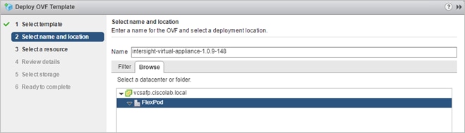
4. Select the destination compute resource and go to the next page.
5. Review the details and go to the next page.
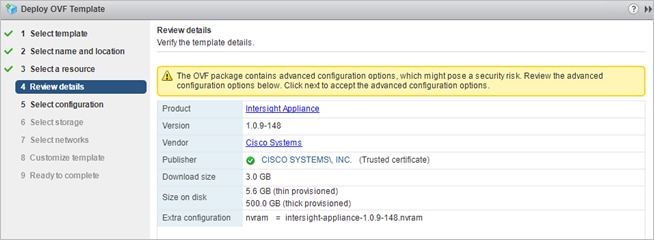
6. Select the appropriate deployment size.
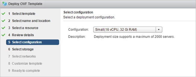
7. Select a destination and thin provision to optimize disk usage on the select storage page.
8. Select a source network and map it to the destination network. This could be the VM management network which has access to all infrastructure elements management.
9. On the Customize Template page, customize the deployment properties of the OVF template and provide network details, an admin password, and NTP and DNS domain/server information. Click Next.
10. Click Finish on the Ready to complete page.
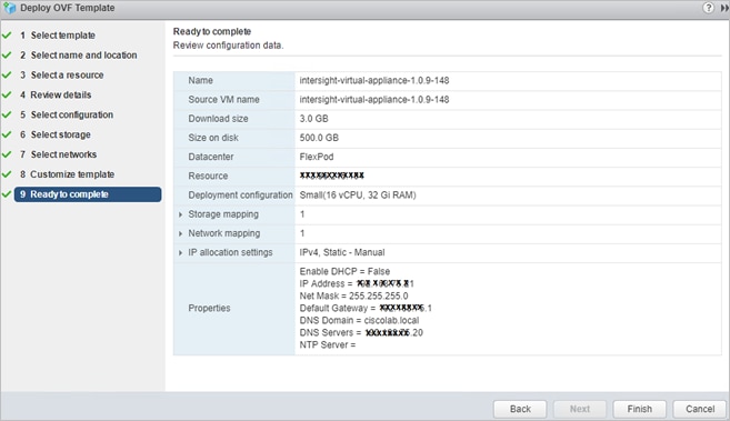
Set Up Cisco Intersight Assist
To set up Cisco Intersight Assist, follow these steps:
1. After installing Cisco Intersight Virtual Appliance, start the VM host in vCenter. After a short period of time, connect to the host using your web browser to proceed with the configuration. Provide your proxy configuration in the settings section to connect the installer to the Internet.
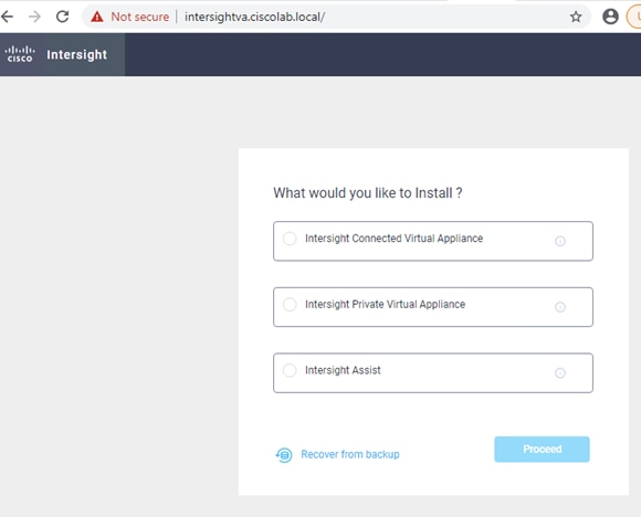
2. Select Intersight Assist and click Proceed to start the two-step approach installation:
a. Connect Intersight Virtual Appliance.
b. Software Download.
The first step provides the Device ID and Claim Code to claim the Virtual Appliance like a standard device in Cisco Intersight.
3. Once connected click Continue to move to the second setup step and wait for the download to complete which can take some time.
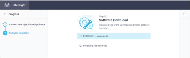
Claim the Fabric Interconnects
To connect and access Cisco Intersight, follow these steps:
1. In Cisco UCS Manager, click the Admin tab in the navigation pane.
2. Choose Device Connector from the drop-down list.
3. Click Settings and provide the DNS, NTP and proxy configuration. Click Save.
4. Enable Intersight Management.
5. In Cisco Intersight, click the Admin > Targets tab in the navigation pane.
6. Click Claim a Net Target.
7. Copy & Paste the Device ID and Claim Code from Cisco USCM.

8. Click Claim to connect the fabric interconnects to Cisco Intersight.
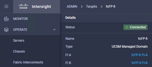
9. Click one of the Fabric Interconnects to review the chassis and server status. From the tool menu it is possible to open a TAC support case from Intersight by uploading the technical support information for further troubleshooting.
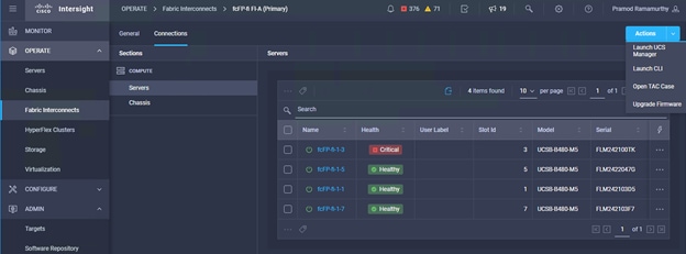
Monitor SAP HANA with AppDynamics
AppDynamics is an Application Performance Monitoring (APM) Platform that helps you to understand and optimize the performance of your business, from its software to infrastructure to business journeys.
The AppDynamics APM Platform enables you to monitor and manage your entire application-delivery ecosystem, from the mobile app or browser client request through your network, backend databases and application servers and more. AppDynamics APM gives you a single view across your application landscape, letting you quickly navigate from the global perspective of your distributed application right down to the call graphs or exception reports generated on individual hosts.
AppDynamics has an agent-based architecture. Once our agents are installed it gives you a dynamic flow map or topography of your application. It uses the concept of traffic lights to indicate the health of your application (green is good, yellow is slow, and red indicates potential issues) with dynamic baselining. AppDynamics measures application performance based on business transactions which essentially are the key functionality of the application. When the application deviates from the baseline AppDynamics captures and provides deeper diagnostic information to help be more proactive in troubleshooting and reduce the MTTR (mean time to resolution).
AppDynamics has a one of its kind ABAP agent for monitoring SAP ABAP systems. We have comprehensive coverage of the SAP landscape with our ABAP, Java, .net and Server visibility agents. In addition, Datavard Insights extends the AppDynamics for SAP solution with system-level monitoring for the overall SAP systems and SAP HANA databases. While AppDynamics agents provides transaction-level visibility, Datavard Insights collects performance metrics, logs, and events, including processes outside of the user business transactions, such as background jobs or IDocs processing.
The complex and proprietary nature of SAP applications makes it difficult to diagnose issues. AppDynamics allows enterprises to instrument SAP applications, monitor performance, and understand the root cause of performance bottlenecks.

To register for a free trial, follow these steps:
1. Connect to https://www.appdynamics.com/free-trial/.
2. Provide the details to sign up for a free trial utilizing an AppDynamics SaaS controller.
3. Once the AppDynamics SaaS Controller has been provisioned, you will receive an email with the information you need for you to login to the Controller.
4. You can download the Java Agent and the Server Visibility Agent directly from the Controller
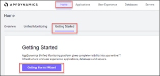
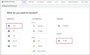
5. You can use the email and password you provided to sign up for the trial to login to the agent download site at the URL listed below and download the ABAP Agent: https://download.appdynamics.com
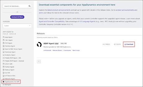
AppDynamics has several types of agents to monitor different language applications to user Experience to Infrastructure monitoring. Based on the SAP landscape and the underlying technology of the SAP systems the agents are installed.
The most frequently installed agents are:
● Java Agent - For Java based SAP Systems
● ABAP Agent - For ABAP based SAP systems
● Server Visibility Agent - Provides extended hardware metrics and Service Availability Monitoring
Please see the link below to verify the supported SAP environments:
https://docs.appdynamics.com/display/SAP/SAP+Supported+Environments
The Java Agent must be installed on SAP Java application servers (for example, Enterprise Portal and PO application servers).
The high-level steps for installing the Java Agent are listed below:
1. Ensure you are logged into the host server as the appropriate <SID>adm OS user.
2. Create the permanent installation directory for the agent.
3. Unzip the file in the permanent directory (such as /usr/sap/appdyn/app).
4. Change the permissions on the contents of the agents' installation directory to give full read/write privileges at the owner and group levels.
5. Edit the configuration file in the agent installation directory to configure the agent to connect to the controller, provide the identity of the JVM, and so on.
7. Use the SAP NetWeaver Administrator or the AS Java Config Tool (depending on your SAP system) to edit the JVM startup parameters. For more detailed information, see: Configuring AppDynamics Java Agent in SAP
8. Restart the SAP JVM for the settings to take effect
9. Validate the Java Agent is reporting to the controller by logging into the controller UI
For detailed information, see: Install the AppDynamics Java Agent
The ABAP Agent needs to be installed on the SAP servers utilizing the ABAP stack.
There are 4 primary steps to perform, each with secondary steps involved. The four primary steps are as follows:
1. Copy and unzip the ABAP Agent.
2. Import the ABAP Agent Transports.
3. Configure ABAP Agent and Install HTTP SDK.
4. Activate Datavard Insight Collectors.
Copy and Unzip ABAP Agent
The high-level steps to copy and unzip the ABAP Agent are listed below:
1. Ensure you are logged into the host server as the appropriate <SID>adm OS user.
2. Copy the agent binary to a temporary directory on the server.
3. Unzip the file into a temporary directory.
4. Change the permissions on the contents of the agents' installation directory to give full read/write privileges at the owner and group levels.
Import the ABAP Agent Transports
![]() There are different versions of data files and cofiles within the ABAP agents’ unzipped directory structure. The specific location of the appropriate files in the agents’ directory structure to use will depend on the version of NetWeaver in use. For more information see: Install on SAP NetWeaver Systems.
There are different versions of data files and cofiles within the ABAP agents’ unzipped directory structure. The specific location of the appropriate files in the agents’ directory structure to use will depend on the version of NetWeaver in use. For more information see: Install on SAP NetWeaver Systems.
The high-level steps to import the ABAP agent transports are listed below:
1. The ABAP Agents data files and cofiles should be copied from the temporary directories where they were unzipped over to the appropriate transport directories for the SAP module in question. For example, for ECC we would copy the transports to "/usr/sap/trans/ECC2/cofiles" and "/usr/sap/trans/ECC2/data."
2. Set the permissions on the cofiles and data files to allow read/write access at the owner and group levels.
3. Log into the SAP system, execute transaction STMS:
a. Go to the import queue of the system where you want to install the ABAP agent.
b. Select "Extras > Other Requests > Add" from the menu bar and add the vendor transports to the import queue one at a time.
4. Import the transports in the appropriate order
The order of the transports is critical and is specified in the “readme.txt” file of the ABAP Agent subdirectory that is specific to the version of NetWeaver in use. For more information please see: Install on SAP NetWeaver Systems
Make sure that when selecting the "Execution" tab in the "Import Transport Request" pop-up dialog box to select the option "Synchronous". When selecting the "Options" tab, put a checkmark next to "Ignore Invalid Component Version".
Configure ABAP Agent / Install HTTP SDK
![]() The steps below assume that your Linux hosts have glibc 2.5+ installed to allow for the automatic HTTP SDK installation. For more information, see: Supported SAP Operating Systems and Installing HTTP SDK Automatically.
The steps below assume that your Linux hosts have glibc 2.5+ installed to allow for the automatic HTTP SDK installation. For more information, see: Supported SAP Operating Systems and Installing HTTP SDK Automatically.
The high-level steps to configure the ABAP agent and install the HTTP SDK are listed below:
1. Log into the SAP system and execute transaction "/DVD/APPD_CUST".
2. Switch to edit mode.
3. Fill in the fields on the screen to configure the agent to connect to the controller, SDK settings, and Analytics API settings.
4. Click Activate integration.
5. Click SDK Installation. This will take you to the "AppDynamics HTTP SDK Installation Manager" screen.
6. Go to Edit > Change Directory:
a. Enter the path that was used for the agents' permanent base install directory (i.e. /usr/sap/appdyn) in the field displayed in the pop-up dialog box shown below, and then click OK.
b. Click Install SDK.
c. Click the green checkmark to exit the screen and return to the "AppDynamics settings" screen.
d. Click Status. This will take you to the "AppDynamics status check" screen.
e. Click Start to start the HTTP SDK proxy on each SAP app server.
Activate Datavard Insight Collectors
Datavard Insights collect detailed performance data for an SAP system. It uses collector jobs that run as periodic background processes in the SAP system. These jobs must be scheduled to run.
Refer to the following links to the related documentation:
Performance Collector Settings
Mapping Between AppDynamics Metrics and Datavard Insights KPIs
Server Visibility Agent Installation
The Server Visibility Agent must be installed on every application server and central services server that will be monitored.
The high-level steps for installing the Server Visibility agent are listed below:
1. Ensure you are logged into the host server as the appropriate <SID>adm OS user.
2. Create the permanent installation directory for the agent.
3. Unzip the file in the permanent directory (such as /usr/sap/appdyn/machine).
4. Change the permissions on the contents of the agents' installation directory to give full read/write privileges at the owner and group levels.
5. Edit the configuration files in the agent installation directory to configure the agent to connect to the controller, provide the identity of the host, and so on.
6. Start the server visibility agent with the script provided in the agents’ bin directory.
7. Validate the server visibility is reporting to the controller by logging into the controller UI.
Automated backup of the UCS domain is important for recovery of the UCS Domain from issues ranging catastrophic failure to human error. There is a native backup solution within Cisco UCS that allows local or remote backup using FTP/TFTP/SCP/SFTP as options.
Backups created can be a binary file containing the Full State, which can be used for a restore to the original or a replacement pair of fabric interconnects. Alternately create the XML configuration file consisting of All configurations, just System configurations, or just Logical configurations of the UCS Domain. For scheduled backups, options will be Full State or All Configuration, backup of just the System or Logical configurations can be manually initiated.
To configure the backup, using the Cisco UCS Manager GUI, follow these steps:
1. Choose Admin within the Navigation pane and choose All.
2. Click the Policy Backup & Export tab within All.
3. For a Full State Backup, All Configuration Backup, or both, specify the following:
a. Hostname: <IP or FQDN of host that will receive the backup>
b. Protocol: [FTP/TFTP/SCP/SFTP]
c. User: <account on host to authenticate>
d. Password: <password for account on host>
e. Remote File: <full path and filename prefix for backup file>
![]() Admin State must be Enabled to fill in the Remote File field.
Admin State must be Enabled to fill in the Remote File field.
f. Admin State: <choose Enable to activate the schedule on save, Disable to disable schedule on Save>
g. Schedule: (Daily/Weekly/Bi Weekly)
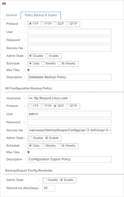
4. Click Save Changes to create the Policy.
The configuration of the Cisco Nexus 9000 and Cisco MDS 9148T switches can be backed up manually at any time with the copy command, but automated backups can be put in place with the NX-OS feature scheduler. An example of setting up automated configuration backups of one of the FlexPod 9336C-FX2 switches is shown below:
conf t
feature scheduler
scheduler logfile size 1024
scheduler job name backup-cfg
copy running-config tftp://<server-ip>/$(SWITCHNAME)-cfg.$(TIMESTAMP) vrf management
exit
scheduler schedule name daily
job name backup-cfg
time daily 2:00
end
![]() On the Cisco MDS 9148T, remove “vrf management” from the copy command.
On the Cisco MDS 9148T, remove “vrf management” from the copy command.
Show the job that has been setup:
show scheduler job
Job Name: backup-cfg
--------------------
copy running-config tftp://10.1.156.150/$(SWITCHNAME)-cfg.$(TIMESTAMP) vrf management
==============================================================================
show scheduler schedule
Schedule Name : daily
---------------------------
User Name : admin
Schedule Type : Run every day at 2 Hrs 0 Mins
Last Execution Time : Yet to be executed
-----------------------------------------------
Job Name Last Execution Status
-----------------------------------------------
backup-cfg -NA-
==============================================================================
The documentation for the feature scheduler can be found here: http://www.cisco.com/c/en/us/td/docs/switches/datacenter/nexus9000/sw/7-x/system_management/configuration/guide/b_Cisco_Nexus_9000_Series_NX-OS_System_Management_Configuration_Guide_7x/b_Cisco_Nexus_9000_Series_NX-OS_System_Management_Configuration_Guide_7x_chapter_01010.html
Pramod Ramamurthy, Technical Marketing Engineer, Cisco Systems, Inc.
Pramod is a Technical Marketing Engineer with Cisco UCS Solutions and Performance Group. Pramod has more than 15 years of experience in the IT industry focusing on SAP technologies. Pramod is currently focusing on the Converged Infrastructure Solutions design, validation and associated collaterals build for SAP HANA.
Marco Schoen, Technical Marketing Engineer, NetApp, Inc.
Marco is a Technical Marketing Engineer with NetApp and has over 20 years of experience in the IT industry focusing on SAP technologies. His specialization areas include SAP NetWeaver Basis technology and SAP HANA. He is currently focusing on the SAP HANA infrastructure design, validation and certification on NetApp Storage solutions and products including various server technologies.
For their support and contribution to the validation of this Cisco Validated Design, we would like to thank:
● Shailendra Mruthunjaya, Cisco Systems Inc.
For comments and suggestions about this guide and related guides, join the discussion on Cisco Community at https://cs.co/en-cvds.