FlexPod Datacenter with Red Hat Enterprise Linux OpenStack Platform Design Guide
Available Languages
FlexPod Datacenter with Red Hat Enterprise Linux OpenStack Platform Design Guide
Last Updated: October 21, 2015

The CVD program consists of systems and solutions designed, tested, and documented to facilitate faster, more reliable, and more predictable customer deployments. For more information visit
http://www.cisco.com/go/designzone.
ALL DESIGNS, SPECIFICATIONS, STATEMENTS, INFORMATION, AND RECOMMENDATIONS (COLLECTIVELY, "DESIGNS") IN THIS MANUAL ARE PRESENTED "AS IS," WITH ALL FAULTS. CISCO AND ITS SUPPLIERS DISCLAIM ALL WARRANTIES, INCLUDING, WITHOUT LIMITATION, THE WARRANTY OF MERCHANTABILITY, FITNESS FOR A PARTICULAR PURPOSE AND NONINFRINGEMENT OR ARISING FROM A COURSE OF DEALING, USAGE, OR TRADE PRACTICE. IN NO EVENT SHALL CISCO OR ITS SUPPLIERS BE LIABLE FOR ANY INDIRECT, SPECIAL, CONSEQUENTIAL, OR INCIDENTAL DAMAGES, INCLUDING, WITHOUT LIMITATION, LOST PROFITS OR LOSS OR DAMAGE TO DATA ARISING OUT OF THE USE OR INABILITY TO USE THE DESIGNS, EVEN IF CISCO OR ITS SUPPLIERS HAVE BEEN ADVISED OF THE POSSIBILITY OF SUCH DAMAGES.
THE DESIGNS ARE SUBJECT TO CHANGE WITHOUT NOTICE. USERS ARE SOLELY RESPONSIBLE FOR THEIR APPLICATION OF THE DESIGNS. THE DESIGNS DO NOT CONSTITUTE THE TECHNICAL OR OTHER PROFESSIONAL ADVICE OF CISCO, ITS SUPPLIERS OR PARTNERS. USERS SHOULD CONSULT THEIR OWN TECHNICAL ADVISORS BEFORE IMPLEMENTING THE DESIGNS. RESULTS MAY VARY DEPENDING ON FACTORS NOT TESTED BY CISCO.
CCDE, CCENT, Cisco Eos, Cisco Lumin, Cisco Nexus, Cisco StadiumVision, Cisco TelePresence, Cisco WebEx, the Cisco logo, DCE, and Welcome to the Human Network are trademarks; Changing the Way We Work, Live, Play, and Learn and Cisco Store are service marks; and Access Registrar, Aironet, AsyncOS, Bringing the Meeting To You, Catalyst, CCDA, CCDP, CCIE, CCIP, CCNA, CCNP, CCSP, CCVP, Cisco, the Cisco Certified Internetwork Expert logo, Cisco IOS, Cisco Press, Cisco Systems, Cisco Systems Capital, the Cisco Systems logo, Cisco Unity, Collaboration Without Limitation, EtherFast, EtherSwitch, Event Center, Fast Step, Follow Me Browsing, FormShare, GigaDrive, HomeLink, Internet Quotient, IOS, iPhone, iQuick Study, IronPort, the IronPort logo, LightStream, Linksys, MediaTone, MeetingPlace, MeetingPlace Chime Sound, MGX, Networkers, Networking Academy, Network Registrar, PCNow, PIX, PowerPanels, ProConnect, ScriptShare, SenderBase, SMARTnet, Spectrum Expert, StackWise, The Fastest Way to Increase Your Internet Quotient, TransPath, WebEx, and the WebEx logo are registered trademarks of Cisco Systems, Inc. and/or its affiliates in the United States and certain other countries.
All other trademarks mentioned in this document or website are the property of their respective owners. The use of the word partner does not imply a partnership relationship between Cisco and any other company. (0809R)
© 2015 Cisco Systems, Inc. All rights reserved.
FlexPod: Cisco and NetApp Verified Architecture
Out of the Box Infrastructure High Availability
Cisco Unified Computing System (UCS)
Cisco UCS 6248UP Fabric Interconnects
Cisco UCS 5108 Blade Server Chassis
Cisco Nexus 9000 Series Switch
Cisco Nexus 1000v for KVM - OpenStack
Cisco Nexus 1000V for OpenStack Solution Offers
ML2 Mechanism Driver for Cisco Nexus 1000v
NetApp Clustered Data ONTAP 8.3 Fundamentals
NetApp Advanced Data Management Capabilities
NetApp E-Series Storage Controllers
NetApp SANtricity Operating System Fundamentals
Domain and Management Software
NetApp OnCommand System Manager
NetApp SANtricity Storage Manager
Red Hat Enterprise Linux OpenStack Platform Installer
Red Hat Enterprise Linux OpenStack Platform
Other OpenStack Supporting Technologies
Hardware and Software Specifications
FlexPod with Red Hat Enterprise Linux OpenStack Platform Physical Topology
FlexPod with Red Hat Enterprise Linux OpenStack Platform Physical Design
MLOM Virtual Interface Card (VIC)
Validated I/O Components and Servers
Fabric Failover for Ethernet: Highly Available vNIC
Cisco UCS Physical Connectivity to Nexus 9000
Cisco UCS QoS and Jumbo Frames
Cisco Nexus 9000 Series Modes of Operation
Cisco Nexus 9000 Standalone Mode Design
IP Based Storage and Boot from iSCSI
Link Aggregation and Virtual Port Channel
Cisco Nexus 1000v for KVM Solution Design
Network and Storage Physical Connectivity
Clustered Data ONTAP Logical Topology Diagram
Clustered Data ONTAP Configuration for OpenStack
Storage Virtual Machine Layout
NetApp E-Series Storage Design
Network and Storage Physical Connectivity
SANtricity OS Configuration for OpenStack
Cisco UCS and NetApp Storage OpenStack Deployment Topology
Hosts Roles and OpenStack Service Placement in Cisco UCS
Red Hat Enterprise Linux OpenStack Platform Installer Network Traffic Types
Cisco Validated Designs consist of systems and solutions that are designed, tested, and documented to facilitate and improve customer deployments. These designs incorporate a wide range of technologies and products into a portfolio of solutions that have been developed to address the business needs of our customers.
The purpose of this document is to describe the Cisco and NetApp® FlexPod® solution, which is a validated approach for deploying Cisco and NetApp technologies as shared cloud infrastructure. This validated design provides a framework of deploying Red Hat Enterprise Linux OpenStack platform on FlexPod.
FlexPod is a leading converged infrastructure supporting broad range of enterprise workloads and use cases. With the growing interest, continuous evolution, and popular acceptance of OpenStack there has been an increased customer demand to have OpenStack platform validated on FlexPod, and be made available for Enterprise private cloud, as well as other OpenStack based Infrastructure as a Service (IaaS) cloud deployments. To accelerate this process and simplify the evolution to a shared cloud infrastructure, Cisco, NetApp, and Red Hat have developed a validated solution, FlexPod with Red Hat Enterprise Linux OpenStack Platform 6.0. This solution enables customers to quickly and reliably deploy OpenStack based private and hybrid cloud on converged infrastructure while offering FlexPod Cooperative Support Model that provides both OpenStack and FlexPod support.
The recommended solution architecture is built on Cisco UCS B200 M4 Blade Servers, Cisco Nexus 9000 Series switches, and NetApp FAS8000 Series and E5000 Series storage arrays. In addition to that, it includes Red Hat Enterprise Linux 7.1, Red Hat Enterprise Linux OpenStack Platform 6.0, and the Red Hat Enterprise Linux OpenStack platform installer.
Introduction
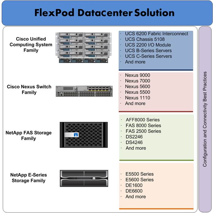
FlexPod is a pre-validated datacenter architecture followed by best practices that is built on the Cisco Unified Computing System (UCS), the Cisco Nexus® family of switches, and NetApp unified storage systems as shown in Figure 1 FlexPod has been a trusted platform for running a variety of virtualization hypervisors as well as bare metal operating systems. The FlexPod architecture is highly modular, delivers a baseline configuration, and also has the flexibility to be sized and optimized to accommodate many different use cases and requirements. The FlexPod architecture can both scale up (adding additional resources within a FlexPod unit) and scale out (adding additional FlexPod units). FlexPod with Red Hat Enterprise Linux OpenStack Platform 6.0 validated design is an extension to FlexPod validated design portfolio to provide OpenStack solution.
OpenStack is a massively scalable open source architecture that controls compute, network, and storage resources through a web user interface. The OpenStack development community operates on a six-month release cycle with frequent updates. Their code base is composed of many loosely coupled OpenStack projects. However, Red Hat’s OpenStack technology addresses these challenges and uses upstream OpenStack open source architecture and enhances it for Enterprise and service provider customers with better quality, stability, installation procedure, and support structure.
Red Hat Enterprise Linux OpenStack Platform 6.0, engineered with Red Hat hardened OpenStack Juno code delivers a stable release for production scale environment. Red Hat Enterprise Linux OpenStack Platform 6.0 adopters have an advantage of immediate access to bug fixes and critical security patches, tight integration with Red Hat’s enterprise security features including SELinux, and a steady release cadence between OpenStack versions.
Cisco Unified Computing System (UCS) is a next-generation datacenter platform that unifies computing, networking, storage access, and virtualization into a single cohesive system, which makes Cisco UCS an ideal platform for OpenStack architecture. Combination of Cisco UCS platform and Red Hat Enterprise Linux OpenStack Platform architecture accelerates your IT transformation by enabling faster deployments, greater flexibility of choice, efficiency, and lower risk. Furthermore, Cisco Nexus family of switches provides the network foundation for next-generation datacenter.
In FlexPod with Red Hat Enterprise Linux OpenStack Platform 6.0, OpenStack block storage (Cinder) is provided by a highly available enterprise-class NetApp FAS array. From a storage standpoint, NetApp Clustered Data ONTAP® provides the means of scale up or scale out, iSCSI boot for all the infrastructure hosts, and non-disruptive operations and upgrade capabilities. For more improved performance, operational efficiency, and reduced data-center footprint, NetApp E-Series provides OpenStack object storage (Swift).
Figure 1 FlexPod Component Families
Audience
The audience of this document includes, but is not limited to, sales engineers, field consultants, professional services, IT managers, partner engineers, and customers who want to take advantage of an infrastructure that is built to deliver IT efficiency and enable IT innovation.
Purpose of this Document
This document describes Red Hat Enterprise Linux OpenStack Platform 6.0, which is based on “Juno” OpenStack release, built on the FlexPod from Cisco and NetApp. This document discusses design choices and best practices of deploying the shared infrastructure.
Solution Summary
The FlexPod® solution portfolio combines NetApp® storage systems, Cisco® Unified Computing System servers, and Cisco Nexus fabric into a single, flexible architecture. FlexPod datacenter can scale up for greater performance and capacity or scale out for environments that require consistent, multiple deployments. FlexPod provides:
· Converged infrastructure of compute, network, and storage components from Cisco and NetApp
· Is a validated enterprise-class IT platform
· Rapid deployment for business critical applications
· Reduces cost, minimizes risks, and increases flexibility and business agility
· Scales up or out for future growth
This solution is based on OpenStack “Juno” release hardened and streamlined by Red Hat Enterprise Linux OpenStack Platform 6.0. The advantages of Cisco Unified Computing System, NetApp, and Red Hat Enterprise Linux OpenStack Platform combine to deliver OpenStack Infrastructure as a Service (IaaS) deployment that is quick and easy to deploy.
FlexPod with Red Hat Enterprise Linux OpenStack Platform helps IT organizations accelerate cloud deployments while retaining control and choice over their environments with open and inter-operable cloud solutions. FlexPod with Red Hat Enterprise Linux OpenStack Platform 6.0 offers fully redundant architecture from compute, network, and storage perspective. Furthermore, it includes OpenStack HA through redundant controller nodes. In this solution, OpenStack storage is provided by highly available NetApp storage sub-systems. The solution comprises of the following key components:
· Cisco Unified Computing System (UCS)
— Cisco UCS 6200 Series Fabric Interconnect
— Cisco VIC 1340
— Cisco UCS 2204XP IO Module or Fabric Extender
— Cisco UCS B200 M4 Blade Server
· Cisco Nexus 9300 Series switch
· Cisco Nexus 1000v switch for KVM
· NetApp Storage
— NetApp FAS8040
— NetApp E-5560
· Red Hat Enterprise Linux 7.1
· Red Hat Enterprise Linux Platform Installer
· Red Hat Enterprise Linux OpenStack Platform 6.0
FlexPod System Overview
FlexPod is a best practice datacenter architecture that includes these components:
· Cisco Unified Computing System (Cisco UCS)
· Cisco Nexus switches
· NetApp fabric-attached storage (FAS) and/or NetApp E-Series storage systems
These components are connected and configured according to best practices of both Cisco and NetApp, and provide the ideal platform for running a variety of enterprise workloads with confidence. As previously mentioned, the reference architecture covered in this document leverages the Cisco Nexus 9000 Series switch. One of the key benefits of FlexPod is the ability to maintain consistency at scaling, including scale up and scale out. Each of the component families shown in Figure 1 (Cisco Unified Computing System, Cisco Nexus, and NetApp storage systems) offers platform and resource options to scale the infrastructure up or down, while supporting the same features and functionality that are required under the configuration and connectivity best practices of FlexPod.
FlexPod Benefits
As customers transition toward shared infrastructure or cloud computing they face a number of challenges such as initial transition hiccups, return on investment (ROI) analysis, infrastructure management and future growth plan. The FlexPod architecture is designed to help with proven guidance and measurable value. By introducing standardization, FlexPod helps customers mitigate the risk and uncertainty involved in planning, designing, and implementing a new datacenter infrastructure. The result is a more predictive and adaptable architecture capable of meeting and exceeding customers' IT demands.
FlexPod: Cisco and NetApp Verified Architecture
Cisco and NetApp have thoroughly validated and verified the FlexPod solution architecture and its many use cases while creating a portfolio of detailed documentation, information, and references to assist customers in transforming their datacenters to this shared infrastructure model. This portfolio includes, but is not limited to the following items:
· Best practice architectural design
· Workload sizing and scaling guidance
· Implementation and deployment instructions
· Technical specifications (rules for FlexPod configuration dos and don’ts)
· Frequently asked questions (FAQs)
· Cisco Validated Designs (CVDs) and NetApp Verified Architectures (NVAs) focused on a variety of use cases
Cisco and NetApp have also built a robust and experienced support team focused on FlexPod solutions, from customer account and technical sales representatives to professional services and technical support engineers. The Co-operative Support Program extended by NetApp, Cisco and Redhat provides customers and channel service partners with direct access to technical experts who collaborate with cross vendors and have access to shared lab resources to resolve potential issues. FlexPod supports tight integration with virtualized and cloud infrastructures, making it a logical choice for long-term investment. The following IT initiatives are addressed by the FlexPod solution.
Integrated System
FlexPod is a pre-validated infrastructure that brings together compute, storage, and network to simplify, accelerate, and minimize the risk associated with datacenter builds and application rollouts. These integrated systems provide a standardized approach in the datacenter that facilitates staff expertise, application onboarding, and automation as well as operational efficiencies relating to compliance and certification.
Out of the Box Infrastructure High Availability
FlexPod is a highly available and scalable infrastructure that IT can evolve over time to support multiple physical and virtual application workloads. FlexPod has no single point of failure at any level, from the server through the network, to the storage. The fabric is fully redundant and scalable, and provides seamless traffic failover, should any individual component fail at the physical or virtual layer.
FlexPod Design Principles
FlexPod addresses four primary design principles:
· Application availability: Makes sure that services are accessible and ready to use.
· Scalability: Addresses increasing demands with appropriate resources.
· Flexibility: Provides new services or recovers resources without requiring infrastructure modifications.
· Manageability: Facilitates efficient infrastructure operations through open standards and APIs.
![]() Performance and comprehensive security are key design criteria that are not directly addressed in this solution but have been addressed in other collateral, benchmarking, and solution testing efforts. This design guide validates the functionality and basic security elements.
Performance and comprehensive security are key design criteria that are not directly addressed in this solution but have been addressed in other collateral, benchmarking, and solution testing efforts. This design guide validates the functionality and basic security elements.
Cisco Unified Computing System (UCS)
The Cisco Unified Computing System is a next-generation solution for blade and rack server computing. The system integrates a low-latency; lossless 10 Gigabit Ethernet unified network fabric with enterprise-class, x86-architecture servers. The system is an integrated, scalable, multi-chassis platform in which all resources participate in a unified management domain. The Cisco Unified Computing System accelerates the delivery of new services simply, reliably, and securely through end-to-end provisioning and migration support for both virtualized and non-virtualized systems. The Cisco Unified Computing System consists of the following components:
· Compute - The system is based on an entirely new class of computing system that incorporates rack mount and blade servers based on Intel Xeon 2600 v2 Series Processors.
· Network - The system is integrated onto a low-latency, lossless, 10-Gbps unified network fabric. This network foundation consolidates LANs, SANs, and high-performance computing networks which are separate networks today. The unified fabric lowers costs by reducing the number of network adapters, switches, and cables, and by decreasing the power and cooling requirements. Virtualization - The system unleashes the full potential of virtualization by enhancing the scalability, performance, and operational control of virtual environments. Cisco security, policy enforcement, and diagnostic features are now extended into virtualized environments to better support changing business and IT requirements. Storage access - The system provides consolidated access to both SAN storage and Network Attached Storage (NAS) over the unified fabric. By unifying the storage access the Cisco Unified Computing System can access storage over Ethernet (SMB 3.0 or iSCSI), Fibre Channel, and Fibre Channel over Ethernet (FCoE). This provides customers with storage choices and investment protection. In addition, the server administrators can pre-assign storage-access policies to storage resources, for simplified storage connectivity and management leading to increased productivity.
· Management - the system uniquely integrates all system components to enable the entire solution to be managed as a single entity by the Cisco UCS Manager. The Cisco UCS Manager has an intuitive graphical user interface (GUI), a command-line interface (CLI), and a powerful scripting library module for Microsoft PowerShell built on a robust application programming interface (API) to manage all system configuration and operations.
Cisco Unified Computing System (Cisco UCS) fuses access layer networking and servers. This high-performance, next-generation server system provides a datacenter with a high degree of workload agility and scalability.
Cisco UCS 6248UP Fabric Interconnects
· The Cisco UCS Fabric interconnects provide a single point for connectivity and management for the entire system. Typically deployed as an active-active pair, the system’s fabric interconnects integrate all components into a single, highly-available management domain controlled by Cisco UCS Manager. The fabric interconnects manage all I/O efficiently and securely at a single point, resulting in deterministic I/O latency regardless of a server or virtual machine’s topological location in the system.
· Cisco UCS 6200 Series Fabric Interconnects support the system’s 80 Gbps unified fabric with low-latency, lossless, cut-through switching that supports IP, storage, and management traffic using a single set of cables. The fabric interconnects feature virtual interfaces that terminate both physical and virtual connections equivalently, establishing a virtualization-aware environment in which blade, rack servers, and virtual machines are interconnected using the same mechanisms. The Cisco UCS 6248UP is a 1-RU Fabric Interconnect that features up to 48 universal ports that can support 80 Gigabit Ethernet, Fiber Channel over Ethernet, or native Fiber Channel connectivity.
For more information, see: http://www.cisco.com/c/en/us/products/servers-unified-computing/ucs-6200-series-fabric-interconnects/index.html
Figure 2 Cisco Fabric Interconnect – Front and Rear

![]()
Cisco UCS 5108 Blade Server Chassis
The Cisco UCS 5100 Series Blade Server Chassis is a crucial building block of the Cisco Unified Computing System, delivering a scalable and flexible blade server chassis. The Cisco UCS 5108 Blade Server Chassis is six rack units (6RU) high and can mount in an industry-standard 19-inch rack. A single chassis can house up to eight half-width Cisco UCS B-Series Blade Servers and can accommodate both half-width and full-width blade form factors. Four single-phase, hot-swappable power supplies are accessible from the front of the chassis. These power supplies are 92 percent efficient and can be configured to support non-redundant, N+ 1 redundant and grid-redundant configurations. The rear of the chassis contains eight hot-swappable fans, four power connectors (one per power supply), and two I/O bays for Cisco UCS 2204XP or 2208XP Fabric Extenders. A passive mid-plane provides up to 40 Gbps of I/O bandwidth per server slot and up to 80 Gbps of I/O bandwidth for two slots. The chassis is capable of supporting future 80 Gigabit Ethernet standards. For more information, see: http://www.cisco.com/c/en/us/products/servers-unified-computing/ucs-5100-series-blade-server-chassis/index.html
Figure 3 Cisco UCS 5108 Blade Chassis
|
Front view |
Back View |
Cisco UCS Fabric Extenders
The Cisco UCS 2204XP Fabric Extender (Figure 4) has four 10 Gigabit Ethernet, FCoE-capable, SFP+ ports that connect the blade chassis to the fabric interconnect. Each Cisco UCS 2204XP has sixteen 10 Gigabit Ethernet ports connected through the mid-plane to each half-width slot in the chassis. Typically configured in pairs for redundancy, two fabric extenders provide up to 80 Gbps of I/O to the chassis.
The Cisco UCS 2208XP Fabric Extender (Figure 4) has eight 10 Gigabit Ethernet, FCoE-capable, Enhanced Small Form-Factor Pluggable (SFP+) ports that connect the blade chassis to the fabric interconnect. Each Cisco UCS 2208XP has thirty-two 10 Gigabit Ethernet ports connected through the midplane to each half-width slot in the chassis. Typically configured in pairs for redundancy, two fabric extenders provide up to 160 Gbps of I/O to the chassis.
Figure 4 Cisco UCS 2204XP/2208XP Fabric Extender
|
Cisco UCS 2204XP FEX |
Cisco UCS 2208XP FEX |
Cisco UCS B200 M4 Servers
The enterprise-class Cisco UCS B200 M4 Blade Server extends the capabilities of Cisco’s Unified Computing System portfolio in a half-width blade form factor. The Cisco UCS B200 M4 uses the power of the latest Intel® Xeon® E5-2600 v3 Series processor family CPUs with up to 768 GB of RAM (using 32 GB DIMMs), two solid-state drives (SSDs) or hard disk drives (HDDs), and up to 80 Gbps throughput connectivity. The UCS B200 M4 Blade Server mounts in a Cisco UCS 5100 Series blade server chassis or UCS Mini blade server chassis. It has 24 total slots for registered ECC DIMMs (RDIMMs) or load-reduced DIMMs (LR DIMMs) for up to 768 GB total memory capacity (B200 M4 configured with two CPUs using 32 GB DIMMs). It supports one connector for Cisco’s VIC 1340 or 1240 adapter, which provides Ethernet and FCoE. For more information, see: http://www.cisco.com/c/en/us/products/servers-unified-computing/ucs-b200-m4-blade-server/index.html
Figure 5 Cisco UCS B200 M4 Blade Server

Cisco VIC 1340
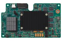
The Cisco UCS Virtual Interface Card (VIC) 1340 is a 2-port 40-Gbps Ethernet or dual 4 x 10-Gbps Ethernet, FCoE-capable modular LAN on motherboard (mLOM) designed exclusively for the M4 generation of Cisco UCS B-Series Blade Servers. When used in combination with an optional port expander, the Cisco UCS VIC 1340 capabilities is enabled for two ports of 40-Gbps Ethernet. The Cisco UCS VIC 1340 enables a policy-based, stateless, agile server infrastructure that can present over 256 PCIe standards-compliant interfaces to the host that can be dynamically configured as either network interface cards (NICs) or host bus adapters (HBAs). In addition, the Cisco UCS VIC 1340 supports Cisco® Virtual Machine Fabric Extender (VM-FEX) technology, which extends the Cisco UCS Fabric interconnect ports to virtual machines, simplifying server virtualization deployment and management. For more information, see: http://www.cisco.com/c/en/us/products/interfaces-modules/ucs-virtual-interface-card-1340/index.html
Figure 6 Cisco VIC 1340
Cisco UCS Differentiators
Cisco’s Unified Compute System is revolutionizing the way servers are managed in data-center. Following are the unique differentiators of Cisco Unified Computing System and Cisco UCS Manager.
1. Embedded Management —In Cisco UCS, the servers are managed by the embedded firmware in the Fabric Interconnects, eliminating need for any external physical or virtual devices to manage the servers.
2. Unified Fabric —In Cisco UCS, from blade server chassis or rack servers to FI, there is a single Ethernet cable used for LAN, SAN and management traffic. This converged I/O results in reduced cables, SFPs and adapters – reducing capital and operational expenses of overall solution.
3. Auto Discovery —By simply inserting the blade server in the chassis or connecting rack server to the fabric interconnect, discovery and inventory of compute resource occurs automatically without any management intervention. The combination of unified fabric and auto-discovery enables the wire-once architecture of UCS, where compute capability of UCS can be extended easily while keeping the existing external connectivity to LAN, SAN and management networks.
4. Policy Based Resource Classification —Once a compute resource is discovered by UCS Manager, it can be automatically classified to a given resource pool based on policies defined. This capability is useful in multi-tenant cloud computing. This CVD showcases the policy based resource classification of UCS Manager.
5. Combined Rack and Blade Server Management —Cisco UCS Manager can manage Cisco UCS B-series blade servers and C-series rack server under the same Cisco UCS domain. This feature, along with stateless computing makes compute resources truly hardware form factor agnostic.
6. Model based Management Architecture —Cisco UCS Manager architecture and management database is model based and data driven. An open XML API is provided to operate on the management model. This enables easy and scalable integration of Cisco UCS Manager with other management systems.
7. Policies, Pools, Templates —The management approach in Cisco UCS Manager is based on defining policies, pools and templates, instead of cluttered configuration, which enables a simple, loosely coupled, data driven approach in managing compute, network and storage resources.
8. Loose Referential Integrity —In Cisco UCS Manager, a service profile, port profile or policies can refer to other policies or logical resources with loose referential integrity. A referred policy cannot exist at the time of authoring the referring policy or a referred policy can be deleted even though other policies are referring to it. This provides different subject matter experts to work independently from each-other. This provides great flexibility where different experts from different domains, such as network, storage, security, server and virtualization work together to accomplish a complex task.
9. Policy Resolution —In Cisco UCS Manager, a tree structure of organizational unit hierarchy can be created that mimics the real life tenants and/or organization relationships. Various policies, pools and templates can be defined at different levels of organization hierarchy. A policy referring to another policy by name is resolved in the organization hierarchy with closest policy match. If no policy with specific name is found in the hierarchy of the root organization, then special policy named “default” is searched. This policy resolution practice enables automation friendly management APIs and provides great flexibility to owners of different organizations.
10. Service Profiles and Stateless Computing —A service profile is a logical representation of a server, carrying its various identities and policies. This logical server can be assigned to any physical compute resource as far as it meets the resource requirements. Stateless computing enables procurement of a server within minutes, which used to take days in legacy server management systems.
11. Built-in Multi-Tenancy Support —The combination of policies, pools and templates, loose referential integrity, policy resolution in organization hierarchy and a service profiles based approach to compute resources makes UCS Manager inherently friendly to multi-tenant environment typically observed in private and public clouds.
12. Extended Memory — The enterprise-class Cisco UCS B200 M4 blade server extends the capabilities of Cisco’s Unified Computing System portfolio in a half-width blade form factor. The Cisco UCS B200 M4 harnesses the power of the latest Intel® Xeon® E5-2600 v3 Series processor family CPUs with up to 1536 GB of RAM (using 64 GB DIMMs) – allowing huge VM to physical server ratio required in many deployments, or allowing large memory operations required by certain architectures like big data.
13. Virtualization Aware Network —Cisco VM-FEX technology makes the access network layer aware about host virtualization. This prevents domain pollution of compute and network domains with virtualization when virtual network is managed by port-profiles defined by the network administrators’ team. VM-FEX also off-loads hypervisor CPU by performing switching in the hardware, thus allowing hypervisor CPU to do more virtualization related tasks. VM-FEX technology is well integrated with VMware vCenter, Linux KVM and Hyper-V SR-IOV to simplify cloud management.
14. Simplified QoS —Even though Fiber Channel and Ethernet are converged in Cisco UCS fabric, built-in support for QoS and lossless Ethernet makes it seamless. Network Quality of Service (QoS) is simplified in Cisco UCS Manager by representing all system classes in one GUI panel.
Cisco UCS for OpenStack
Cloud-enabled applications can run on organization premises, in public clouds, or on a combination of the two (hybrid cloud) for greater flexibility and business agility. Finding a platform that supports all these scenarios is essential. With Cisco UCS, IT departments can take advantage of technological advancements and lower the cost of their OpenStack deployments.
1. Open Architecture—A market-leading, open alternative to expensive, proprietary environments, the simplified architecture of Cisco UCS running OpenStack software delivers greater scalability, manageability, and performance at a significant cost savings compared to traditional systems, both in the datacenter and the cloud. Using industry-standard x86-architecture servers and open source software, IT departments can deploy cloud infrastructure today without concern for hardware or software vendor lock-in.
2. Accelerated Cloud Provisioning—Cloud infrastructure must be able to flex on demand, providing infrastructure to applications and services on a moment’s notice. Cisco UCS simplifies and accelerates cloud infrastructure deployment through automated configuration. The abstraction of Cisco Unified Compute System Integrated Infrastructure for Red Hat Enterprise Linux server identity, personality, and I/O connectivity from the hardware allows these characteristics to be applied on demand. Every aspect of a server’s configuration, from firmware revisions and BIOS settings to network profiles, can be assigned through Cisco UCS Service Profiles. Cisco service profile templates establish policy-based configuration for server, network, and storage resources and can be used to logically preconfigure these resources even before they are deployed in the cloud infrastructure.
3. Simplicity at Scale—With IT departments challenged to deliver more applications and services in shorter time frames, the architectural silos that result from an ad hoc approach to capacity scaling with traditional systems poses a barrier to successful cloud infrastructure deployment. Start with the computing and storage infrastructure needed today and then scale easily by adding components. Because servers and storage systems integrate into the unified system, they do not require additional supporting infrastructure or expert knowledge. The system simply, quickly, and cost-effectively presents more computing power and storage capacity to cloud infrastructure and applications.
4. Virtual Infrastructure Density—Cisco UCS enables cloud infrastructure to meet ever-increasing guest OS memory demands on fewer physical servers. The system’s high-density design increases consolidation ratios for servers, saving the capital, operating, physical space, and licensing costs that would be needed to run virtualization software on larger servers. With Cisco UCS B200 M4 latest Intel Xeon E5-2600 v3 Series processor up to 1536 GB of RAM (using 64 GB DIMMs), OpenStack deployments can host more applications using less-expensive servers without sacrificing performance.
5. Simplified Networking—In OpenStack environments, underlying infrastructure can become sprawling complex of networked systems. Unlike traditional server architecture, Cisco UCS provides greater network density with less cabling and complexity. Cisco’s unified fabric integrates Cisco UCS servers with a single high-bandwidth, low-latency network that supports all system I/O. This approach simplifies the architecture and reduces the number of I/O interfaces, cables, and access-layer switch ports compared to the requirements for traditional cloud infrastructure deployments. This unification can reduce network complexity by up to a factor of three, and the system’s wire-once network infrastructure increases agility and accelerates deployment with zero-touch configuration.
6. Installation Confidence—Organizations that choose OpenStack for their cloud can take advantage of the Red Hat Enterprise Linux OpenStack Platform Installer. This software performs the work needed to install a validated OpenStack deployment. Unlike other solutions, this approach provides a highly available, highly scalable architecture for OpenStack services.
7. Easy Management—Cloud infrastructure can be extensive, so it must be easy and cost effective to manage. Cisco UCS Manager provides embedded management of all software and hardware components in Cisco UCS. Cisco UCS Manager resides as embedded software on the Cisco UCS fabric interconnects, fabric extenders, servers, and adapters. No external management server is required, simplifying administration and reducing capital expenses for the management environment.
Cisco Nexus 9000 Series Switch
The Cisco Nexus 9000 Series delivers proven high performance and density, low latency, and exceptional power efficiency in a broad range of compact form factors. Operating in Cisco NX-OS Software mode or in Application Centric Infrastructure (ACI) mode, these switches are ideal for traditional or fully automated datacenter deployments.
Figure 7 Cisco Nexus 9000 Series

The Cisco Nexus 9000 Series Switches offer both modular and fixed 10/40/100 Gigabit Ethernet switch configurations with scalability up to 30 Gbps of non-blocking performance with less than five-microsecond latency, 1152 10 Gbps or 288 40 Gbps non-blocking Layer 2 and Layer 3 Ethernet ports and wire speed VXLAN gateway, bridging, and routing support. For more information, see: http://www.cisco.com/c/en/us/products/switches/nexus-9000-series-switches/index.html
Cisco Nexus 1000v for KVM - OpenStack
Cisco Nexus 1000V OpenStack solution is an enterprise-grade virtual networking solution, which offers Security, Policy control and Visibility all with Layer2/Layer 3 switching at the hypervisor, layer. Cisco Nexus 1000V provides state-full firewall functionality within your infrastructure to isolate tenants and enables isolation of virtual machines with policy-based VM attributes. Cisco Nexus 1000V’s robust policy framework enables centralized enterprise-compliant policy management, pre-provisioning of policies on a network-wide basis and simplifies policy additions and modifications across the virtual infrastructure. When it comes to application visibility, Cisco Nexus 1000V provides insight into live and historical VM migrations and advanced automated troubleshooting capabilities to identify problems in seconds. It also enables you to use your existing monitoring tools to provide rich analytics and auditing capabilities across your physical and virtual infrastructure.
Layer2/Layer3 Switching – Cisco Nexus 1000V offers the capability to route East-West traffic within the tenant without having to go to an external router. This capability reduces sub-optimal traffic patterns within the network and increases the network performance.
East-West Security – Cisco Nexus 1000V comes with Cisco Virtual Security Gateway (VSG) which provides layer 2 zone based firewall capability. Using VSG, Nexus 1000V can secure east west machine to machine traffic by providing stateful firewall functionality. VSG also enables the users to define security attributes based on VM attributes along with network attributes.
Policy Frame Work – Cisco Nexus 1000V provides an extremely power policy frame work to define polices per tenant and make these policies available to the end user via Horizon Dashboard or via Neutron API. This policy framework consists of the popular port profiles and the network policy (For example, VLAN, VxLAN). All these polices can be centrally managed which makes it easier to roll out new business polices or modify existing business polices instantaneously
Application Visibility – Nexus 1000V brings in a slew of industry proven monitoring features that exist in the physical Nexus infrastructure to virtual networking. To name few of them, Nexus 1000V provides remote-monitoring capabilities by using SPAN/ERSPAN, provides visibility into VM motion by using vTacker and provides consolidated interface status, traffic statistics using Virtual Supervisor Module (VSM)
All the monitoring, management and functionality features offered on the Nexus 1000V are consentient with the physical Nexus infrastructure. This enables customer to reuse the existing tool chains to manage the new virtual networking infrastructure as well. Also, customers can experience a seamless functionality in the virtual network homogenous to the physical network.
Cisco Nexus 1000V for OpenStack Solution Offers
Table 1 Use Cases
| Use Case |
Description |
| Micro-Segmentation |
· Stateful firewall functionality for East – West traffic (Layer 2 Zone based firewall) · VM isolation in a common layer 2 segment (tenant) with no additional security group’s |
| VM Visibility |
· Monitoring of live application traffic and collect user statistics · Insight into live and past VM migrations |
| Policy Control |
· Centralized location for policy management · Flexible and powerful frame work that enables organizations to pre provision network wide policies · Policies available via Horizon and Neutron API |
Cisco Nexus 1000V Components
Cisco Nexus 1000v brings the same robust architecture associated with traditional Cisco physical modular switches and with other virtualization environments (for example, VMware vSphere and Microsoft Hyper-V) to OpenStack deployments.
The Cisco Nexus1000v has the following main components:
· The Cisco Nexus® 1000V Virtual Ethernet Module (VEM) is a software component that is deployed on each Kernel-based Virtual Machine (KVM) host. Each virtual machine on the host is connected to the VEM through virtual Ethernet (vEth) ports.
· The Cisco Nexus 1000V Virtual Supervisor Module (VSM) is the management component that controls multiple VEMs and helps in the definition of virtual machine-focused network policies. It is deployed either as a virtual appliance on any KVM host or on the CiscoCloud Services Platform appliance.
· The Cisco Virtual Extensible LAN (VXLAN) Gateway is a gateway appliance to facilitate communication between a virtual machine located on a VXLAN with other entities (bare-metal servers, physical firewalls etc.) that are connected to traditional VLANs. It can be deployed as a virtual appliance on any KVM host.
· The OpenStack Neutron plug-in is used for communication between the VSM and OpenStack Neutron service and is deployed as part of the OpenStack Neutron service.
· The OpenStack Horizon integration for policy profile.
Each of these components are tightly integrated with the OpenStack environment:
· The VEM is a hypervisor-resident component and is tightly integrated with the KVM architecture.
· The VSM is integrated with OpenStack using the OpenStack Neutron plug-in.
· The OpenStack Neutron API has been extended to include two additional user-defined resources:
— Network profiles are logical groupings of network segments.
— Policy profiles group port policy information, including security, monitoring, and quality-of-service (QoS) policies.
![]() In Cisco Nexus 1000v for KVM Release 5.2(1) SK3 (2.2a), network profiles are created automatically for each network type. Network profile creation by administrators is not supported.
In Cisco Nexus 1000v for KVM Release 5.2(1) SK3 (2.2a), network profiles are created automatically for each network type. Network profile creation by administrators is not supported.
ML2 Mechanism Driver for Cisco Nexus 1000v
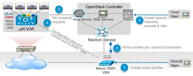
In Red Hat Enterprise Linux OpenStack Platform 6.0, The Cisco Nexus 1000v plugin added support for accepting REST API responses in JSON format from Virtual Supervisor Module (VSM) as well as control for enabling Policy Profile visibility across tenants. Figure 8 shows the operational workflow in OpenStack environment.
Figure 8 Cisco Nexus 1000v ML2 Driver Workflow
NetApp FAS8000
This FlexPod datacenter solution includes the NetApp fabric-attached storage (FAS) 8040 series unified scale-out storage system for both the OpenStack Block Storage Service (Cinder) and the OpenStack Image Service (Glance). Powered by NetApp Clustered Data ONTAP, the FAS8000 series unifies the SAN and NAS storage infrastructure. Systems architects can choose from a range of models representing a spectrum of cost-versus-performance points. Every model, however, provides the following core benefits:
· HA and fault tolerance. Storage access and security are achieved through clustering, high availability (HA) pairing of controllers, hot-swappable components, NetApp RAID DP® disk protection (allowing two independent disk failures without data loss), network interface redundancy, support for data mirroring with NetApp SnapMirror® software, application backup integration with the NetApp SnapManager® storage management software, and customizable data protection with the NetApp Snap Creator® framework and SnapProtect® products.
· Storage efficiency. Users can store more data with less physical media. This is achieved with thin provisioning (unused space is shared among volumes), NetApp Snapshot® copies (zero-storage, read-only clones of data over time), NetApp FlexClone® volumes and LUNs (read/write copies of data in which only changes are stored), deduplication (dynamic detection and removal of redundant data), and data compression.
· Unified storage architecture. Every model runs the same software (clustered Data ONTAP); supports all popular storage protocols (CIFS, NFS, iSCSI, FCP, and FCoE); and uses SATA, SAS, or SSD storage (or a mix) on the back end. This allows freedom of choice in upgrades and expansions, without the need for re-architecting the solution or retraining operations personnel.
· Advanced clustering. Storage controllers are grouped into clusters for both availability and performance pooling. Workloads can be moved between controllers, permitting dynamic load balancing and zero-downtime maintenance and upgrades. Physical media and storage controllers can be added as needed to support growing demand without downtime.
NetApp Storage Controllers
A storage system running Data ONTAP (also known as a storage controller) is the hardware device that receives and sends data from the host. Controller nodes are deployed in HA pairs, with these HA pairs participating in a single storage domain or cluster. This unit detects and gathers information about its own hardware configuration, the storage system components, the operational status, hardware failures, and other error conditions. A storage controller is redundantly connected to storage through disk shelves, which are the containers or device carriers that hold disks and associated hardware such as power supplies, connectivity interfaces, and cabling.
The NetApp FAS8000 features a multicore Intel chipset and leverages high-performance memory modules, NVRAM to accelerate and optimize writes, and an I/O-tuned PCIe gen3 architecture that maximizes application throughput. The FAS8000 series come with integrated unified target adapter (UTA2) ports that support 16 GB Fibre Channel, 10GbE, or FCoE. Figure 9 shows a front and rear view of the FAS8040/8060 controllers.
Figure 9 NetApp FAS8040/8060 (6U) - Front and Rear View

If storage requirements change over time, NetApp storage offers the flexibility to change quickly as needed without expensive and disruptive forklift upgrades. This applies to different types of changes:
· Physical changes, such as expanding a controller to accept more disk shelves and subsequently more hard disk drives (HDDs) without an outage
· Logical or configuration changes, such as expanding a RAID group to incorporate these new drives without requiring any outage
· Access protocol changes, such as modification of a virtual representation of a hard drive to a host by changing a logical unit number (LUN) from FC access to iSCSI access, with no data movement required, but only a simple dismount of the FC LUN and a mount of the same LUN, using iSCSI
In addition, a single copy of data can be shared between Linux and Windows systems while allowing each environment to access the data through native protocols and applications. In a system that was originally purchased with all SATA disks for backup applications, high-performance solid-state disks can be added to the same storage system to support Tier-1 applications, such as Oracle®, Microsoft Exchange, or Microsoft SQL Server.
For more NetApp FAS8000 information, see: http://www.netapp.com/us/products/storage-systems/fas8000/
NetApp Clustered Data ONTAP 8.3 Fundamentals
NetApp provides enterprise-ready, unified scale out storage with clustered Data ONTAP 8.3, the operating system physically running on the storage controllers in the NetApp FAS storage appliance. Developed from a solid foundation of proven Data ONTAP technology and innovation, clustered Data ONTAP is the basis for large virtualized shared-storage infrastructures that are architected for non-disruptive operations over the system lifetime.
![]() Clustered Data ONTAP 8.3 is the first Data ONTAP release to support clustered operation only. The previous version of Data ONTAP, 7-Mode, is not available as a mode of operation in version 8.3.
Clustered Data ONTAP 8.3 is the first Data ONTAP release to support clustered operation only. The previous version of Data ONTAP, 7-Mode, is not available as a mode of operation in version 8.3.
Data ONTAP scale-out is one way to respond to growth in a storage environment. All storage controllers have physical limits to their expandability; the number of CPUs, memory slots, and space for disk shelves dictate maximum capacity and controller performance. If more storage or performance capacity is needed, it might be possible to add CPUs and memory or install additional disk shelves, but ultimately the controller becomes completely populated, with no further expansion possible. At this stage, the only option is to acquire another controller. One way to do this is to scale up; that is, to add additional controllers in such a way that each is an independent management entity that does not provide any shared storage resources. If the original controller is completely replaced by a newer, larger controller, data migration is required to transfer the data from the old controller to the new one. This is time consuming and potentially disruptive and most likely requires configuration changes on all of the attached host systems.
If the newer controller can coexist with the original controller, then the two storage controllers must be individually managed, and there are no native tools to balance or reassign workloads across them. The situation becomes worse as the number of controllers increases. If the scale-up approach is used, the operational burden increases consistently as the environment grows, and the end result is a very unbalanced and difficult-to-manage environment. Technology refresh cycles require substantial planning in advance, lengthy outages, and configuration changes, which introduce risk into the system.
In contrast, when using a scale-out approach, additional controllers are added seamlessly to the resource pool residing on a shared storage infrastructure as the storage environment grows. Host and client connections as well as volumes can move seamlessly and non-disruptively anywhere in the resource pool, so that existing workloads can be easily balanced over the available resources, and new workloads can be easily deployed. Technology refreshes (replacing disk shelves, adding or completely replacing storage controllers) are accomplished while the environment remains online and continues serving data.
Although scale-out products have been available for some time, these were typically subject to one or more of the following shortcomings:
· Limited protocol support. NAS only.
· Limited hardware support. Supported only a particular type of storage controller or a very limited set.
· Little or no storage efficiency. Thin provisioning, de-duplication, compression.
· Little or no data replication capability.
Therefore, while these products are well positioned for certain specialized workloads, they are less flexible, less capable, and not robust enough for broad deployment throughout the enterprise.
Data ONTAP is the first product to offer a complete scale-out solution, and it offers an adaptable, always-available storage infrastructure for today’s highly virtualized environment.
Scale Out
Datacenters require agility. In a datacenter, each storage controller has CPU, memory, and disk shelf limits. Scale-out means that as the storage environment grows, additional controllers can be added seamlessly to the resource pool residing on a shared storage infrastructure. Host and client connections as well as volumes can be moved seamlessly and non-disruptively anywhere within the resource pool. The benefits of scale-out include:
· Non-disruptive operations
· The ability to add tenants, instances, volumes, networks, and so on without downtime in OpenStack
· Operational simplicity and flexibility
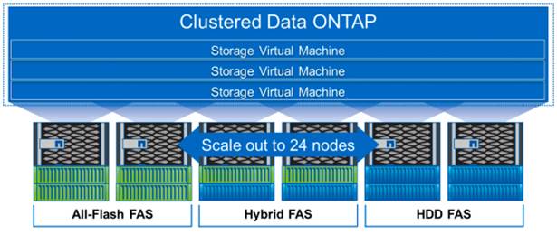
As Figure 10 shows, NetApp Clustered Data ONTAP offers a way to solve the scalability requirements in a storage environment. A NetApp Clustered Data ONTAP system can scale up to 24 nodes, depending on platform and protocol, and can contain different disk types and controller models in the same storage cluster with up to 101PB of capacity.
Figure 10 NetApp Clustered Data ONTAP
Non-disruptive Operations
The move to shared infrastructure has made it nearly impossible to schedule downtime for routine maintenance. NetApp clustered Data ONTAP is designed to eliminate the need for planned downtime for maintenance operations and lifecycle operations as well as the unplanned downtime caused by hardware and software failures. NetApp storage solutions provide redundancy and fault tolerance through clustered storage controllers and redundant, hot-swappable components, such as cooling fans, power supplies, disk drives, and shelves. This highly available and flexible architecture enables customers to manage all data under one common infrastructure while meeting mission-critical uptime requirements.
Three standard tools that eliminate the possible downtime:
· NetApp DataMotion™ data migration software for volumes (vol move). Allows you to move data volumes from one aggregate to another on the same or a different cluster node.
· Logical interface (LIF) migration. Allows you to virtualize the physical Ethernet interfaces in clustered Data ONTAP. LIF migration allows the administrator to move these virtualized LIFs from one network port to another on the same or a different cluster node.
· Aggregate relocate (ARL). Allows you to transfer complete aggregates from one controller in an HA pair to the other without data movement.
Used individually and in combination, these tools allow you to non-disruptively perform a full range of operations, from moving a volume from a faster to a slower disk all the way up to a complete controller and storage technology refresh.
As storage nodes are added to the system, all physical resources (CPUs, cache memory, network I/O bandwidth, and disk I/O bandwidth) can be easily kept in balance. NetApp Data ONTAP enables users to:
· Move data between storage controllers and tiers of storage without disrupting users and applications
· Dynamically assign, promote, and retire storage, while providing continuous access to data as administrators upgrade or replace storage
· Increase capacity while balancing workloads and reduce or eliminate storage I/O hot spots without the need to remount shares, modify client settings, or stop running applications.
These features allow a truly non-disruptive architecture in which any component of the storage system can be upgraded, resized, or re-architected without disruption to the private cloud infrastructure.
Availability
Shared storage infrastructure provides services to many different tenants in an OpenStack deployment. In such environments, downtime produces disastrous effects. The NetApp FAS eliminates sources of downtime and protects critical data against disaster through two key features:
· High Availability (HA). A NetApp HA pair provides seamless failover to its partner in the event of any hardware failure. Each of the two identical storage controllers in the HA pair configuration serves data independently during normal operation. During an individual storage controller failure, the data service process is transferred from the failed storage controller to the surviving partner.
· RAID-DP®. During any OpenStack deployment, data protection is critical because any RAID failure might disconnect and/or shutoff hundreds or potentially thousands of end users from their virtual machines, resulting in lost productivity. RAID-DP provides performance comparable to that of RAID 10 and yet it requires fewer disks to achieve equivalent protection. RAID-DP provides protection against double-disk failure, in contrast to RAID 5, which can protect against only one disk failure per RAID group, in effect providing RAID 10 performance and protection at a RAID 5 price point.
For more information, see: Clustered Data ONTAP 8.3 High-Availability Configuration Guide
NetApp Advanced Data Management Capabilities
This section describes the storage efficiencies, advanced storage features, and multiprotocol support capabilities of the NetApp FAS8000 storage controller.
Storage Efficiencies
NetApp FAS includes built-in thin provisioning, data deduplication, compression, and zero-cost cloning with FlexClone that offers multilevel storage efficiency across OpenStack instances, installed applications, and user data. This comprehensive storage efficiency enables a significant reduction in storage footprint, with a capacity reduction of up to 10:1, or 90% (based on existing customer deployments and NetApp solutions lab validation). Four features make this storage efficiency possible:
· Thin provisioning. Allows multiple applications to share a single pool of on-demand storage, eliminating the need to provision more storage for one application if another application still has plenty of allocated but unused storage.
· De-duplication. Saves space on primary storage by removing redundant copies of blocks in a volume that hosts hundreds of instances. This process is transparent to the application and the user, and it can be enabled and disabled on the fly or scheduled to run at off-peak hours.
· Compression. Compresses data blocks. Compression can be run whether or not deduplication is enabled and can provide additional space savings whether it is run alone or together with deduplication.
· FlexClone. Offers hardware-assisted rapid creation of space-efficient, writable, point-in-time images of individual VM files, LUNs, or flexible volumes. The use of FlexClone technology in OpenStack deployments provides high levels of scalability and significant cost, space, and time savings. The NetApp Cinder driver provides the flexibility to rapidly provision and redeploys thousands of instances.
Advanced Storage Features
NetApp Data ONTAP provides a number of additional features, including:
· NetApp Snapshot™ copy. A manual or automatically scheduled point-in-time copy that writes only changed blocks, with no performance penalty. A Snapshot copy consumes minimal storage space because only changes to the active file system are written. Individual files and directories can easily be recovered from any Snapshot copy, and the entire volume can be restored back to any Snapshot state in seconds. A NetApp Snapshot incurs no performance overhead. Users can comfortably store up to 255 NetApp Snapshot copies per NetApp FlexVol® volume, all of which are accessible as read-only and online versions of the data.
![]() NetApp Snapshots are taken at the FlexVol level, so they cannot be directly leveraged within an OpenStack user context. This is because a Cinder user requests that a Snapshot be taken of a particular Cinder volume, not the containing FlexVol volume. Because a Cinder volume is represented as either a file in the NFS or as a LUN (in the case of iSCSI or Fibre Channel), Cinder snapshots can be created by using FlexClone, which allows you to create many thousands of Cinder snapshots of a single Cinder volume.
NetApp Snapshots are taken at the FlexVol level, so they cannot be directly leveraged within an OpenStack user context. This is because a Cinder user requests that a Snapshot be taken of a particular Cinder volume, not the containing FlexVol volume. Because a Cinder volume is represented as either a file in the NFS or as a LUN (in the case of iSCSI or Fibre Channel), Cinder snapshots can be created by using FlexClone, which allows you to create many thousands of Cinder snapshots of a single Cinder volume.
NetApp Snapshots are however available to OpenStack administrators to do administrative backups, create and/or modify data protection policies, etc.
· LIF. A logical interface that is associated with a physical port, interface group, or VLAN interface. More than one LIF may be associated with a physical port at the same time. There are three types of LIFs: NFS LIFs, iSCSI LIFs, and Fibre Channel LIFs. LIFs are logical network entities that have the same characteristics as physical network devices but are not tied to physical objects. LIFs used for Ethernet traffic are assigned specific Ethernet-based details such as IP addresses and iSCSI qualfied names and then are associated with a specific physical port capable of supporting Ethernet. LIFs used for FC-based traffic are assigned specific FC-based details such as worldwide port names (WWPNs) and then are associated with a specific physical port capable of supporting FC or FCoE. NAS LIFs can be non-disruptively migrated to any other physical network port throughout the entire cluster at any time, either manually or automatically (by using policies), whereas SAN LIFs rely on MPIO and ALUA to notify clients of any change in the network topology.
· Storage Virtual Machines (SVMs). An SVM is a secure virtual storage server that contains data volumes and one or more LIFs, through which it serves data to the clients. An SVM securely isolates the shared, virtualized data storage and network and appears as a single dedicated server to its clients. Each SVM has a separate administrator authentication domain and can be managed independently by an SVM administrator.
Unified Storage Architecture and Multiprotocol Support
NetApp also offers the NetApp Unified Storage Architecture as well. The term “unified” refers to a family of storage systems that simultaneously support SAN (through FCoE, Fibre Channel (FC), and iSCSI) and network-attached storage (NAS) (through CIFS and NFS) across many operating environments, including OpenStack, VMware®, Windows, Linux, and UNIX. This single architecture provides access to data by using industry-standard protocols, including NFS, CIFS, iSCSI, FCP, SCSI, and NDMP.
Connectivity options include standard Ethernet (10/100/1000Mb or 10GbE) and Fibre Channel (4, 8, or 16 Gb/sec). In addition, all systems can be configured with high-performance solid-state drives (SSDs) or serial-attached SCSI (SAS) disks for primary storage applications, low-cost SATA disks for secondary applications (backup, archive, and so on), or a mix of the different disk types. By supporting all common NAS and SAN protocols on a single platform, NetApp FAS enables:
· Direct access to storage for each client
· Network file sharing across different platforms without the need for protocol-emulation products such as SAMBA, NFS Maestro, or PC-NFS
· Simple and fast data storage and data access for all client systems
· Fewer storage systems
· Greater efficiency from each system deployed
NetApp Clustered Data ONTAP can support several protocols concurrently in the same storage system and data replication and storage efficiency features are supported across all protocols. The following are supported:
· NFS v3, v4, and v4.1, including pNFS
· iSCSI
· Fibre Channel
· FCoE
· SMB 1, 2, 2.1, and 3
Storage Virtual Machines
The secure logical storage partition through which data is accessed in clustered Data ONTAP is known as an SVM. A cluster serves data through at least one and possibly multiple SVMs. An SVM is a logical abstraction that represents a set of physical resources of the cluster. Data volumes and logical network LIFs are created and assigned to an SVM and can reside on any node in the cluster to which the SVM has been given access. An SVM can own resources on multiple nodes concurrently, and those resources can be moved non-disruptively from one node to another. For example, a flexible volume can be non-disruptively moved to a new node, and an aggregate, or a data LIF, can be transparently reassigned to a different physical network port. The SVM abstracts the cluster hardware and is not tied to specific physical hardware.
An SVM is capable of supporting multiple data protocols concurrently. Volumes within the SVM can be combined together to form a single NAS namespace, which makes all of an SVM’s data available to NFS and CIFS clients through a single share or mount point. For example, a 24-node cluster licensed for UNIX and Windows File Services that has a single SVM configured with thousands of volumes can be accessed from a single network interface on one of the nodes. SVMs also support block-based protocols, and LUNs can be created and exported by using iSCSI, FC, or FCoE. Any or all of these data protocols can be configured for use within a given SVM.
An SVM is a secure entity. Therefore, it is aware of only the resources that have been assigned to it and has no knowledge of other SVMs and their respective resources. Each SVM operates as a separate and distinct entity with its own security domain. Tenants can manage the resources allocated to them through a delegated SVM administration account. An SVM is effectively isolated from other SVMs that share the same physical hardware, and as such, is uniquely positioned to align with OpenStack tenants for a truly comprehensive multi-tenant environment. Each SVM can connect to unique authentication zones, such as AD, LDAP, or NIS.
From a performance perspective, maximum IOPS and throughput levels can be set per SVM by using QoS policy groups, which allow the cluster administrator to quantify the performance capabilities allocated to each SVM.
Clustered Data ONTAP is highly scalable, and additional storage controllers and disks can easily be added to existing clusters to scale capacity and performance to meet rising demands. Because these are virtual storage servers within the cluster, SVMs are also highly scalable. As new nodes or aggregates are added to the cluster, the SVM can be non-disruptively configured to use them. New disk, cache, and network resources can be made available to the SVM to create new data volumes or to migrate existing workloads to these new resources to balance performance.
This scalability also enables the SVM to be highly resilient. SVMs are no longer tied to the lifecycle of a given storage controller. As new replacement hardware is introduced, SVM resources can be moved non-disruptively from the old controllers to the new controllers, and the old controllers can be retired from service while the SVM is still online and available to serve data.
SVMs have three main components:
· Logical interfaces. All SVM networking is done through LIFs created within the SVM. As logical constructs, LIFs are abstracted from the physical networking ports on which they reside.
· Flexible volumes. A flexible volume is the basic unit of storage for an SVM. An SVM has a root volume and can have one or more data volumes. Data volumes can be created in any aggregate that has been delegated by the cluster administrator for use by the SVM. Depending on the data protocols used by the SVM, volumes can contain either LUNs for use with block protocols, files for use with NAS protocols, or both concurrently. For access using NAS protocols, the volume must be added to the SVM namespace through the creation of a client-visible directory called a junction.
· Namespaces. Each SVM has a distinct namespace through which all of the NAS data shared from that SVM can be accessed. This namespace can be thought of as a map to all of the junctioned volumes for the SVM, regardless of the node or the aggregate on which they physically reside. Volumes can be junctioned at the root of the namespace or beneath other volumes that are part of the namespace hierarchy. For more information about namespaces, see: NetApp TR-4129: Namespaces in Clustered Data ONTAP.
For more information on Data ONTAP, see: NetApp Data ONTAP 8.3 Operating System.
NetApp E5000 Series
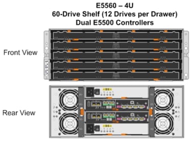
This FlexPod Datacenter solution also makes use of the NetApp E-Series E5560 storage system, primarily for the OpenStack Object Storage service (Swift). An E5560 is comprised of dual E5500 controllers mated with the 4U 60 drive DE6600 chassis. The NetAppÒ E5500 storage system family is designed to meet the most demanding and data-intensive applications and provide continuous access to data. It is from the E-Series line, which offers zero-scheduled downtime systems, redundant hot-swappable components, automated path failover, and online administration capabilities.
The E5560 is shown in Figure 11.
Figure 11 NetApp E-Series E5560
NetApp E-Series Storage Controllers
The E5000 Series hardware delivers an enterprise level of availability with:
· Dual-active controllers, fully redundant I/O paths, and automated failover
· Battery-backed cache memory that is destaged to flash upon power loss
· Extensive monitoring of diagnostic data that provides comprehensive fault isolation, simplifying analysis of unanticipated events for timely problem resolution
· Proactive repair that helps get the system back to optimal performance in minimum time
This storage system additionally provides the following high-level benefits:
· Flexible Interface Options. The E-Series supports a complete set of host or network interfaces designed for either direct server attachment or network environments. With multiple ports per interface, the rich connectivity provides ample options and bandwidth for high throughput. The interfaces include quad-lane SAS, iSCSI, FC, and InfiniBand to connect with and protect investments in storage networking.
· High Availability and Reliability. The E-Series simplifies management and maintains organizational productivity by keeping data accessible through redundant components, automated path failover, and online administration, including online SANtricity® OS and drive firmware updates. Advanced protection features and extensive diagnostic capabilities deliver high levels of data integrity, including Data Assurance (T10-PI) to protect against silent drive errors.
· Maximum Storage Density and Modular Flexibility. The E-Series offers multiple form factors and drive technology options to best meet your storage requirements. The ultra-dense 60-drive system shelf supports up to 360TB in just 4U of space. It is perfect for environments with large amounts of data and limited floor space. Its high-efficiency power supplies and intelligent design can lower power use up to 40% and cooling requirements by up to 39%.
· Intuitive Management. NetApp SANtricity Storage Manager software offers extensive configuration flexibility, optimal performance tuning, and complete control over data placement. With its dynamic capabilities, SANtricity software supports on-the-fly expansion, reconfigurations, and maintenance without interrupting storage system I/O.
For more information on the NetApp E5560, see: NetApp E5500 Storage System.
NetApp SANtricity Operating System Fundamentals
With over 20 years of storage development behind it, and approaching nearly one million systems shipped, the E-Series platform is based on a field-proven architecture that uses the SANtricity storage management software on the controllers. This OS is designed to provide high reliability and greater than 99.999% availability, data integrity, and security. The SANtricity OS:
· Delivers best-in-class reliability with automated features, online configuration options, state-of-the-art RAID, proactive monitoring, and NetApp AutoSupport™ capabilities.
· Extends data protection through FC- and IP-based remote mirroring, NetApp SANtricity Dynamic Disk Pools (DDPs), enhanced Snapshot copies, data-at-rest encryption, data assurance to ensure data integrity, and advanced diagnostics.
· Includes plug-ins for application-aware deployments of Oracle®, VMware®, Microsoft®, and Splunk® applications.
For more information, see the NetApp SANtricity Operating System product page.
Dynamic Disk Pools
DDPs increase the level of data protection, provide more consistent transactional performance, and improve the versatility of E-Series systems. DDP dynamically distributes data, spare capacity, and parity information across a pool of drives. An intelligent algorithm (seven patents pending) determines which drives are used for data placement, and data is dynamically recreated and redistributed as needed to maintain protection and uniform distribution.
Consistent Performance during Rebuilds
DDP minimizes the performance drop that can occur during a disk rebuild, allowing rebuilds to complete up to eight times faster than with traditional RAID. Therefore, your storage spends more time in an optimal performance mode that maximizes application productivity. Shorter rebuild times also reduce the possibility of a second disk failure occurring during a disk rebuild and protects against unrecoverable media errors. Stripes with several drive failures receive priority for reconstruction.
Overall, DDP provides a significant improvement in data protection; the larger the pool, the greater the protection. A minimum of 11 disks is required to create a disk pool.
How DDP Works
When a disk fails with traditional RAID, data is recreated from parity on a single hot spare drive, creating a bottleneck. All volumes using the RAID group suffer. DDP distributes data, parity information, and spare capacity across a pool of drives. Its intelligent algorithm based on CRUSH defines which drives are used for segment placement, ensuring full data protection. DDP dynamic rebuild technology uses every drive in the pool to rebuild a failed drive, enabling exceptional performance under failure. Flexible disk-pool sizing optimizes utilization of any configuration for maximum performance, protection, and efficiency.
When a disk fails in a Dynamic Disk Pool, reconstruction activity is spread across the pool and the rebuild is completed eight times faster.
Figure 12 Dynamic Disk Pool

NetApp Storage for OpenStack
Most options for OpenStack integrated storage solutions aspire to offer scalability, but often lack the features and performance needed for efficient and cost-effective cloud deployment at scale.
NetApp has developed OpenStack interfaces to provide FAS and E-Series value to enterprise customers and thus provides them with a choice in cloud infrastructure deployment, including open-source options that provide lower cost, faster innovation, unmatched scalability, and the promotion of standards. As OpenStack abstracts the underlying hardware from customer applications and workloads, NetApp enterprise storage features and functionality can be exposed through unique integration capabilities built for OpenStack. Features are passed through the interfaces such that standard OpenStack management tools (CLI, Horizon, etc.) can be used to access NetApp value proposition for simplicity and automation.
Once exposed through the abstraction of the OpenStack API set, NetApp technology features are now accessible, such as data deduplication, thin provisioning, cloning, Snapshots, DDPs, mirroring, and so on. Customers can be confident that the storage infrastructure underlying their OpenStack Infrastructure as a Service (IaaS) environment is highly available, flexible, and performant.
Because NetApp technology is integrated with
· OpenStack Block Storage Service (Cinder)
· OpenStack Object Storage Service (Swift)
· OpenStack Image Service (Glance)
· OpenStack Compute Service (Nova)
· OpenStack File Share Service (Manila)
Users can build on this proven and highly scalable storage platform not only with greenfield deployments as illustrated in this CVD, and also with brownfield deployments for customers who wish to optimize their existing NetApp storage infrastructure.
Cinder
The OpenStack Block Storage service provides management of persistent block storage resources. In addition to acting as secondarily attached persistent storage, you can write images into a Cinder volume for Nova to utilize as a bootable, persistent root volume for an instance.
In this Cisco Validated Design, Cinder volumes are stored on the NetApp FAS8040 storage array and accessed using the pNFS (NFS version 4.1) protocol. The pNFS protocol has a number of advantages at scale in a large, heterogeneous hybrid cloud, including dynamic failover of network paths, high performance through parallelization, and an improved NFS client.
Red Hat Enterprise Linux OpenStack Platform Installer Integration
The Cinder service configurations (and pertinent configuration files on the resulting Controller hosts) are handled automatically as a part an OpenStack Deployment from within the Red Hat Enterprise Linux OpenStack Platform Installer. Customers can select NetApp within the Services Configuration plane of a deployment. (Figure 13)
Figure 13 Red Hat Enterprise Linux OpenStack Platform Installer Cinder NetApp Integration
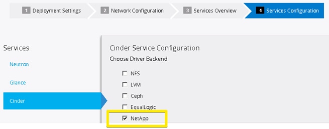
Selectable options include support for NetApp Clustered Data ONTAP, Data ONTAP 7-mode, and E-Series platforms. In this reference architecture, NetApp Clustered Data ONTAP is selected, and pertinent details are filled in that are representative for a NetApp FAS8040 storage subsystem.
NetApp Unified Driver for Clustered Data ONTAP with NFS
A Cinder driver is a particular implementation of a Cinder backend that maps the abstract APIs and primitives of Cinder to appropriate constructs within the particular storage solution underpinning the Cinder backend.
The NetApp Unified Driver for clustered Data ONTAP with NFS is a driver interface from OpenStack block storage to a Data ONTAP cluster system. This software provisions and manages OpenStack volumes on NFS exports provided by the Data ONTAP cluster system. The NetApp Unified Driver for the Data ONTAP cluster does not require any additional management software to achieve the desired functionality because it uses NetApp APIs to interact with the Data ONTAP cluster. It also does not require additional configuration in addition to selecting NetApp during an OpenStack Deployment in the Red Hat Enterprise Linux OpenStack Platform installer.
In this Cisco Validated Design, we take advantage of the NetApp Unified Driver using the NetApp driver backend through the Red Hat Enterprise Linux OpenStack Platform Installer. All of the resulting UCS blades that are provisioned with Red Hat Enterprise Linux 7.1 mount the appropriately designated NetApp FlexVols on the FAS8040 at the highest protocol level possible for the instance volumes (NFS version 4.1 or Parallelized NFS [pNFS]).
![]() A FlexVol volume is a logical container for one or more Cinder volumes.
A FlexVol volume is a logical container for one or more Cinder volumes.
NetApp’s contribution strategy involves adding all new capabilities directly into the upstream OpenStack repositories, so that all of the features are available in Red Hat Enterprise Linux OpenStack Platform 6.0 out of the box. More information regarding the NetApp Unified Driver (including other protocols available) can be found in the following location: NetApp Data ONTAP Drivers for OpenStack Block Storage (Cinder).
More information as to why NFS was chosen over iSCSI in this CVD can be found in the following location: Deployment Choice: NFS versus iSCSI.
More information regarding Clustered Data ONTAP with NFSv4 features can be found in the following location: TR-4067: Clustered Data ONTAP NFS Implementation Guide.
Storage Service Catalog
The Storage Service Catalog (SSC) enables efficient, repeated, and consistent use and management of storage resources by the definition of policy-based services and the mapping of those services to the backend storage technology. It is meant to abstract away the actual technical implementations of the features at a storage backend into a set of simplified configuration options.
These storage features are organized or combined into groups based on a customer’s particular scenario or use case. Based on this catalog of storage features, intelligent provisioning decisions are made by infrastructure or software enabling the SSC. In OpenStack, this is achieved by both the Cinder filter scheduler and the NetApp driver by making use of volume type extra-specs support together with the filter scheduler. There are some prominent features that are exposed in the NetApp driver, including mirroring, deduplication, compression, and thin provisioning. Workloads can be tied to Cinder volume types in an OpenStack context, which then have inherent NetApp technology enabled on the storage system. Examples needing functionality include:
· Transactional databases that require high IOPS with SSD disks, and data protection
· Test and development workloads that would benefit from thin provisioning and compression
· Disaster recovery processes that need a SnapMirror relationship to another NetApp storage system
When you use the NetApp Unified Driver with a clustered Data ONTAP storage system, you can leverage extra specs with Cinder volume types to ensure that Cinder volumes are created on storage backends that have certain properties configured (for example, QoS, mirroring, and compression). Extra specifications are associated with Cinder volume types, so that when users request volumes of a particular volume type, they are created on storage backends that meet the list of requirements (for example, available space, extra specs, and so on).
In this Cisco Validated Design, we create five different OpenStack-specific NetApp flexible volumes on the FAS8040 with different features enabled that can be selected intelligently based on the Cinder scheduler and the NetApp Cinder driver.
More information regarding available extra-specs are available in the following location: Using Cinder Volume Types to Create a Storage Service Catalog.
Swift
OpenStack Object Storage provides a fully distributed, scale-out, API-accessible storage platform that can be integrated directly into applications or used for backup, archiving and data retention. Object storage does not present a traditional file system, but rather a distributed storage system for static data such as: virtual machine images, photo storage, email storage, backups, and archives.
Customers can start with the ultra-dense 60 drive enclosure as demonstrated in this Cisco Validated Design, and then can scale horizontally with multiple controller pairs as the size of the object storage needs grow. Swift data is hosted on the NetApp E5560 storage array using the iSCSI protocol. Three of the UCS servers are used as Swift nodes and handle account, container, and object services. In addition, these three nodes also serve as Proxy servers for the Swift service.
E-Series Resiliency
E-Series storage can effectively serve as the storage medium for Swift. The data reconstruction capabilities associated with DDP eliminates the need for data replication within zones in Swift. DDP reconstruction provides RAID-6 “like” data protection against multiple simultaneous drive failures within the storage subsystem. Data that resides on multiple failed drives is given top priority during reconstruction. This data has the highest potential for being lost if a third drive failure occurs and is thus reconstructed first on the remaining optimal drives in the storage subsystem. After this critical data is reconstructed, all other data on the failed drives is reconstructed. This prioritized data reconstruction dramatically reduces the possibility of data loss due to drive failure.
As disk sizes increase, the rebuild time after failure also increases. The time taken by the traditional RAID systems to rebuild after a failure to an idle spare becomes more longer. This is because the idle spare in the traditional RAID receives all of the write traffic during a rebuild, slowing down the system and data access during this process. One of the main goals of DDP is to spread the workload around if a disk fails and its data must be rebuilt. This provides consistent performance, keeps you in the green zone, and maintains a non-disruptive level of performance. DDP has shown the ability that provide up to eight times faster reconstruction of a failed disk’s data throughout the pool when compared to an equivalent standard RAID-configuration disk rebuild.
The dynamic process of redistributing the data occurs in the background in a non-disruptive, minimal-impact manner so that the I/O continues to flow.
Scalability on NetApp E-Series
Swift uses zoning to isolate the cluster into separate partitions and isolate the cluster from failures. Swift data is replicated across the cluster in as unique-as-possible zones. Typically, zones are established using physical attributes of the cluster, including geographical locations, separate networks, equipment racks, storage subsystems, or even single drives. Zoning allows the cluster to function and tolerate equipment failures without data loss or loss of connectivity to the remaining cluster.
By default, Swift replicates data 3 times across the cluster. Swift replicates data across zones in a unique way that promotes high availability and high durability. Swift chooses a server in an unused zone before it chooses an unused server in a zone that already has a replica of the data. E-Series data reconstruction makes sure that clients always have access to data regardless of drive or other component failures within the storage subsystem. When E-Series storage is used, Swift data replication counts that are specified when rings are built can be reduced from 3 to 2. This dramatically reduces the replication traffic normally sent on the standard IPv4 datacenter networks.
Reduction in Physical Resources using Swift on NetApp E-Series
In addition to the previously discussed issues, using Swift on NetApp E-Series enables:
· Reduced Swift node hardware requirements. Internal drive requirements for storage nodes are reduced, and only operating system storage is required. Disk space for Swift object data, and optionally the operating system itself, is supplied by the E-Series storage array.
· Reduced rack space, power, cooling and footprint requirements. Because a single storage subsystem provides storage space for multiple Swift nodes, smaller and possibly lower power 1U nodes can be used in the cluster.
Red Hat Enterprise Linux OpenStack Platform 6.0 Installer Integration
Swift is not installed through the Red Hat Enterprise Linux OpenStack Platform Installer. Instructions on installing Swift after an OpenStack deployment are provided in the deployment guide.
For more information regarding Swift on NetApp is available in the following location: OpenStack Object Storage Service (Swift).
Glance
The OpenStack Image Service provides discovery, registration and delivery services for virtual machine, disk, and server images. Glance provides a RESTful API that allows the querying of VM image metadata as well as the retrieval of the actual image. A stored image can be used as a template to start up new servers quickly and consistently as opposed to provisioning multiple servers, installing a server operating system, and individually configuring additional services. Such an image can also be used to store and catalog an unlimited number of backups.
In this Cisco Validated Design, Glance is utilized using NFS version 4.0 back to the NetApp FAS8040 storage array. Glance can store disk and server images in a variety of backends (called stores), which are featured as NFS in this CVD.
Red Hat Enterprise Linux OpenStack Platform Installer Integration
Glance configuration like Cinder is handled through an intuitive menu-based interface from within the Red Hat Enterprise Linux OpenStack Platform Installer. Before an OpenStack Deployment is launched, Glance is configured in the Red Hat Enterprise Linux OpenStack Platform Installer to utilize an already configured NetApp FlexVol through NFS with deduplication enabled.
![]() Because there is a high probability of duplicate blocks in a repository of virtual machine images, NetApp highly recommends enabling deduplication on the FlexVol volume(s) where the images are stored.
Because there is a high probability of duplicate blocks in a repository of virtual machine images, NetApp highly recommends enabling deduplication on the FlexVol volume(s) where the images are stored.
Image Formats: QCOW and Raw
Glance supports a variety of image formats, but raw and QCOW2 are the most common. QCOW2 does provide some advantages over the raw format (for example, the support of copy-on-write, snapshots, and dynamic expansion), However, when images are copied into Cinder volumes, they are automatically converted into the raw format once stored on a NetApp backend. Therefore:
· The QCOW2 image format is recommended for ephemeral disks due to its inherent benefits when taking instance snapshots.
· The raw image format can be advantageous when Cinder volumes are used as persistent boot disks, as a conversion from an alternate format to raw that would be performed by Cinder can be avoided.
Both the raw and QCOW2 formats respond well to NetApp deduplication technology, which is often utilized with Glance deployments.
QCOW2 is not Live Migration safe on NFS when the cache=writeback setting is enabled, which is commonly used for performance improvement of QCOW2. If space savings are the desired outcome for the Image Store, raw format files are actually created as sparse files on the NetApp storage system. Deduplication within NetApp FlexVol volumes happens globally rather than only within a particular file, resulting in much better aggregate space efficiency than QCOW2 can provide. Deduplication processing can be finely controlled to run at specific times of day (off peak).
Copy Offload Tool
The NetApp Copy Offload tool was added in the Icehouse release to enable the efficient copying of Glance images to a destination Cinder volume. When Cinder and Glance are configured to use the NetApp NFS Copy Offload tool, a controller-side copy is attempted before reverting to downloading the image from Glance through a normal network copy. This improves image provisioning times while reducing the consumption of bandwidth and CPU cycles on the host(s) running Glance and Cinder. This is due to the copy operation being performed completely within the storage cluster.
![]() If Cinder and Glance share the same NetApp FlexVol, the Copy Offload tool is not necessary. Rather, a direct API call to the NetApp storage system is utilized through the NetApp Unified driver that facilitates a controller-side copy relative to a network copy.
If Cinder and Glance share the same NetApp FlexVol, the Copy Offload tool is not necessary. Rather, a direct API call to the NetApp storage system is utilized through the NetApp Unified driver that facilitates a controller-side copy relative to a network copy.
For more information on this functionality, including a helpful process flowchart, see: NetApp Copy Offload tool.
Rapid Cloning
NetApp provides two capabilities that enhance instance booting by using persistent disk images in the shortest possible time and in the most storage-capacity-efficient manner possible: the NetApp Copy Offload tool and instance caching.
This Enhanced Persistent Instance Creation feature (sometimes referred to as rapid cloning) uses NetApp FlexClone technology and the NetApp Copy Offload tool. The Enhanced Persistent Instance Creation feature can significantly decrease the time needed for the Nova service to fulfill image provisioning and boot requests. It also allows for much larger images with no noticeable degradation of boot time.
One feature that facilitates rapid cloning in an NFS/pNFS setup within the NetApp Unified Driver is instance caching. Whenever a Cinder volume is created out of a Glance template, it is cached locally on the NetApp FlexVol that hosts the Cinder volume instance. Later, when you want to create the same OS instance again, Cinder creates a space-efficient file clone. This clone does not take up any more space because it shares the same blocks as the cached image. Only deltas take up new blocks on the disk. Figure 14 illustrates this concept.
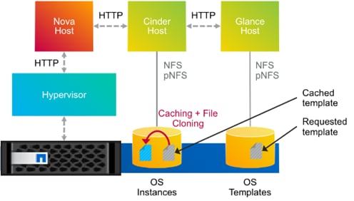
This not only makes the instance/Cinder volume create operation faster, but it also reduces the CPU load on the Cinder/Glance hosts and reduces the network traffic almost completely. The cache also provides a time-to-live option, which invalidates old cache entries automatically after a specified period of time.
For more information regarding Glance on NetApp, see: OpenStack Image Service (Glance).
Nova
The OpenStack Compute Service (Nova) is a cloud computing fabric controller that is the primary part of an IaaS system. You can use the OpenStack Compute service to host and manage cloud instances (virtual machines).
Root and Ephemeral Disks
Each instance requires at least one root disk containing the bootloader and core operating system files, and each instance might also have optional ephemeral disks that use the definition of the flavor selected at instance creation time. The content for the root disk comes either from an image stored within the Glance repository, which is copied to storage attached to the destination hypervisor, or from a persistent block storage volume through Cinder.
By selecting the Boot from Image (Creates a New Volume) option in Nova, you can leverage the enhanced instance creation capabilities described previously. Normally volumes created as a result of this option are persistent beyond the life of the instance. However, you can select the Delete on Terminate option in combination with the Boot from Image (Creates a New Volume) option to create an ephemeral volume while still leveraging the Rapid Cloning capabilities described in the section Rapid Cloning. This can provide a significantly faster provisioning and boot sequence relative to the normal way that ephemeral disks are provisioned. In the normal way, a copy of the disk image is made from Glance to local storage on the hypervisor node where the instance resides. A Glance instance image of 20GB can, for example, be cloned in 300ms using NetApp FlexClone technology.
For more information on using the Nova service in conjunction with NetApp, see: OpenStack Compute Service (Nova).
Manila
NetApp has developed a new OpenStack module called Manila to provide a shared file-system service. Much of the total storage shipped worldwide is based on shared file systems, and, with help from the OpenStack community, NetApp is delivering these capabilities to the OpenStack environment. Before Manila, OpenStack only had the Cinder module for block files. NetApp designed, prototyped, and built the Manila module, which is the equivalent of Cinder for shared or distributed file systems. Manila has emerged as an official, independent project in the Grizzly release of OpenStack.
![]() Manila is not included in the official Red Hat package repositories for Red Hat Enterprise Linux OpenStack Platform 6.0, and is thus not featured in this CVD.
Manila is not included in the official Red Hat package repositories for Red Hat Enterprise Linux OpenStack Platform 6.0, and is thus not featured in this CVD.
RPM Packages exist for Manila on Red Hat Enterprise Linux 7 at the following location, but are unsupported: https://repos.fedorapeople.org/repos/openstack/openstack-kilo/el7/
Support for Manila will be in future releases of Red Hat Enterprise Linux OpenStack Platform.
NetApp Storage platforms integrated with OpenStack provide a unique combination of advanced storage efficiency, integrated data protection, and non-disruptive operations combined with the ability to scale while preserving performance.
For more information on NetApp Storage for OpenStack, see:
· NetApp OpenStack Deployment and Operations Guide
· Highly Available OpenStack Deployments Built on NetApp Storage Systems.
Domain and Management Software
FlexPod with Red Hat Enterprise Linux OpenStack Platform 6.0 leverages the following domain and management software:
Cisco UCS Manager
Cisco Unified Computing System (UCS) Manager provides unified, embedded management for all software and hardware components in the Cisco UCS. Using SingleConnect technology, it manages, controls, and administers multiple chassis for thousands of virtual machines. Administrators use the software to manage the entire Cisco Unified Computing System as a single logical entity through an intuitive GUI, a command-line interface (CLI), or an XML API. The Cisco UCS Manager resides on a pair of Cisco UCS 6200 Series Fabric Interconnects using a clustered, active-standby configuration for high availability.
UCS Manager offers unified embedded management interface that integrates server, network, and storage. UCS Manger performs auto-discovery to detect inventory, manage, and provision system components that are added or changed. It offers comprehensive set of XML API for third part integration, exposes 9000 points of integration and facilitates custom development for automation, orchestration, and to achieve new levels of system visibility and control.
Service profiles benefit both virtualized and non-virtualized environments and increase the mobility of non-virtualized servers, such as when moving workloads from server to server or taking a server offline for service or upgrade. Profiles can also be used in conjunction with virtualization clusters to bring new resources online easily, complementing existing virtual machine mobility. For more Cisco UCS Manager information, see: http://www.cisco.com/c/en/us/products/servers-unified-computing/ucs-manager/index.html
NetApp OnCommand System Manager
NetApp OnCommand System Manager is a simple, versatile GUI management product that enables administrators to easily configure and manage clustered NetApp storage systems. System Manager is designed with wizards and workflows that simplify common storage tasks such as creating volumes, LUNs, qtrees, shares, and exports, which saves time and helps prevent errors. OnCommand System manager manages the entire NetApp FAS line, from the entry-level FAS2200 series to the enterprise-class FAS8000 series, including systems running NetApp FlexArray storage virtualization software.
![]() OnCommand System Manager is now bundled “on-box” with Data ONTAP 8.3 as a web service using HTML5. System Manager is enabled by default with Data ONTAP 8.3, and is accessible by a web browser pointed at the cluster management interface through HTTPS using the cluster administrator credentials.
OnCommand System Manager is now bundled “on-box” with Data ONTAP 8.3 as a web service using HTML5. System Manager is enabled by default with Data ONTAP 8.3, and is accessible by a web browser pointed at the cluster management interface through HTTPS using the cluster administrator credentials.
OnCommand System Manager has some of the following key features:
· An intuitive browser-based GUI
· A wizard-driven configuration to get up and running quickly
· An automated non-disruptive (Data ONTAP) upgrade
· Storage provisioning and disk aggregate management
· CIFS, NFS, iSCSI, FC, and FCoE configuration
· Snapshot and SnapMirror management
· SnapVault support
· Storage virtual machine management
· Monitoring of HA pairs
· Support for all NetApp FAS systems and FlexArray software
· Support for NetApp All Flash FAS
· Support for up to 24 nodes
For more information, see: NetApp OnCommand System Manager
NetApp SANtricity Storage Manager
NetApp SANtricity Storage Manager offers a powerful, easy-to-use interface for administering E-Series storage systems. With SANtricity software, your storage administrators can achieve maximum performance and utilization of storage through extensive configuration flexibility and custom performance tuning. The online administration, advanced data protection features, and extensive diagnostic capabilities of the SANtricity operating system mean your data is always available and fully protected on the storage system.
· Intuitive GUI. Blending robust functionality and ease of use, SANtricity Storage Manager is well suited for both full-time storage administrators who want complete control over their storage configuration, and part-time system administrators who prefer an intuitive interface and wizards that are designed to simplify storage management
· Multi-platform Client Support. Supported operating systems for the SANtricity Storage Manager client are Windows (32 and 64-bit); Linux (32 and 64-bit x86, 64-bit PowerPC, and 64-bit PowerPC Little Endian); IBM AIX; and Solaris (x86 and SPARC).
For more information, see: SANtricity Storage Manager 11.20, or Introduction to NetApp E-Series E5500 with SANtricity 11.20.
Red Hat Enterprise Linux OpenStack Platform Installer
Red Hat Enterprise Linux OpenStack Platform installer manages the provisioning of Red Hat Enterprise Linux OpenStack Platform components on a set of machines. Red Hat Enterprise Linux OpenStack Platform installer provides web-based graphical user interface for managing the installation, configuration, and scalability of OpenStack environments. The application achieves this through discovering bootable hosts and mapping OpenStack services to them via web interface. Installer uses DHCP, DNS, and PXE services to perform OpenStack deployment on remote hosts.
Red Hat Enterprise Linux
Red Hat Enterprise Linux 7.1 lays the foundation for the open hybrid cloud and serves enterprise workloads across converged infrastructure. Red Hat Enterprise Linux 7.1 works on four platforms: Bare metal servers, virtual machines (VM), OpenStack based Infrastructure-as-a-Service (IaaS), and Platform-as-a-Service (PaaS) clouds. These, in turn, can be used together to form a robust, powerful datacenter and cloud environment for business. While Red Hat Enterprise Linux 7.1 still uses Kernel Virtual Machine (KVM) for datacenter and cloud virtualization, it also adopts container technology so that users can get even more applications working on the same server hardware. Red Hat Enterprise Linux 7.1 provides many stability and performance upgrades.
Red Hat Enterprise Linux OpenStack Platform
Red Hat Enterprise Linux OpenStack Platform provides Infrastructure-as-a-Service (IaaS) foundation for public, private or hybrid cloud computing environment on top of Red Hat Enterprise Linux. Red Hat Enterprise Linux OpenStack Platform meets enterprise requirements with ability to extensively scale and provide a fault tolerant and highly available environment.
OpenStack is made up of many different moving parts. Because of its open nature, anyone can add additional components to OpenStack to meet their requirements. The Red Hat Enterprise Linux OpenStack Platform IaaS cloud is implemented by a collection of interacting services that control its computing, storage, and networking resources.
OpenStack Services
OpenStack has modular architecture with various services as its components.
Nova – Compute Service
Nova is the primary computing engine behind OpenStack and provides the base for OpenStack IaaS functionality. It can scale out horizontally on standard hardware in a distributed and asynchronous fashion, imparting fault tolerant and cost effective computing environment for virtual machines. The compute resources access can be controlled by virtual hardware profiles and tenants. They are used for deploying and managing large numbers of virtual machines and other instances that handle computing tasks.
Keystone – Identity Service
Keystone provides identity services for OpenStack. Identity Service provides a central directory of users mapped to the OpenStack services they can access. It acts as a common authentication system across the cloud operating system and can integrate with existing backend directory services. The Identity Service is comprised of the Keystone service, which responds to service requests, places messages in queue, grants access tokens, and updates the state database.
Cinder – Block Storage Service
OpenStack Cinder service provides compute instances with persistent block storage. Block storage is appropriate for performance sensitive scenarios such as databases, expandable file systems, or providing a server with access to raw block level storage. Persistent block storage can survive instance termination and can also be moved across instances like any external storage device. Cinder has volume snapshots capability for backing up the volumes.
Cinder allows for a variety of (pluggable) storage backend including both open source and proprietary. This solution uses storage systems from NetApp as the storage backend.
Neutron – Networking Service
OpenStack Networking is a scalable API-driven service for managing networks and IP addresses. OpenStack Networking gives users self-service control over their network configurations. Users can define, separate, and join networks on demand. Neutron API includes support for Layer 2 (L2) networking as well as an extension for layer 3 (L3) router constructions that enables routing between L2 networks and gateways to external networks. This allows for flexible network models to fit the requirements of different applications. OpenStack Networking has a pluggable architecture that supports numerous virtual networking technologies as well as native Linux networking mechanisms including Open vSwitch and Linux Bridge.
Horizon – Dashboard
Horizon is the dashboard behind OpenStack that provides administrators and users a graphical interface to access, provision and automate cloud- based resources. Developers can access all of the components of OpenStack individually through an application programming interface (API) The dashboard provides system administrators a view of what is going on in the cloud, and to manage it as necessary. The dashboard runs through an HTTP service.
Glance – Image Service
Glance provides image services to OpenStack. Glance allows these images to be used as templates when deploying new virtual machine instances. OpenStack Image Service (Glance) provides discovery, registration, and delivery services for disk and server images. It can also be used to store and catalog multiple backups. The Image Service can store disk and server images in a variety of back-ends, including OpenStack object storage. The Image Service API provides a standard rest interface for querying information about disk images and lets clients stream the images to new servers.
Swift – Object Storage
Swift is OpenStack’s object service. Swift is a distributed scale-out that is highly available and provides for eventual consistency of data. Swift can be used to store lots of data efficiently, safely, and cheaply. Swift is also OpenStack’s default backup store.
Heat – Orchestration Service
OpenStack Heat is an orchestration service that manages the life-cycle of applications within an OpenStack environment using templates. Heat is capable of deploying multi- instance applications called stacks and managing application lifecycle.
Ceilometer – Telemetry Service
Ceilometer provides telemetry services for billing services to individual users of the cloud. It keeps a verifiable count of each user’s system usage of various components of an OpenStack cloud. The delivery of counters is traceable and auditable.
Heat Templates
Heat templates are written in a declarative format. A template defines what resources to deploy rather than how to deploy those resources. This is similar to the approach used by popular configuration tools such as Puppet, Ansible, and Chef. Configuration tools focus on the configuration of a system, whereas Heat focuses on resource provision and relies on cloud-init scripting to handle system configuration. A template may create and configure a large list of resources thus supporting complex application stacks
OpenStack High Availability
OpenStack Environment consists of stateless, shared-nothing services such as Keystone, Glance, Swift, Nova, Neutron, Horizon, Heat, Ceilometer, etc. and underlying infrastructure components that OpenStack services use for inter-service communication and to save persistent data such as MariaDB database, and a message broker called RabbitMQ.
Building a scale-out controller would require setting the services and infrastructure components (database and message broker) in Active-Active configuration. You need to confirm that they are capable of adding more nodes to the cluster as the load increases, and load balancing, the API can request among the nodes. While most of the services are Active-Active, there are some services still in Active-Passive mode.
Red Hat Enterprise Linux OpenStack Platform is now fully integrated with the Red Hat Enterprise Linux High Availability Add-On, to support highly available environments for customer deployments. This means that a cloud infrastructure can now be set up so that if one of its controller nodes/service fails, the machine/service can be brought back up with no or minimal impact.
Memcached
Memcached is fast in-memory key-value cache software that is used by OpenStack components for caching data and increasing performance.
Galera
Galera Cluster is a synchronous multi-master cluster for MariaDB with a valuable availability and scaling features required for OpenStack services.
HAProxy
HAProxy is a software layer-7 load balancer used to cater to all clustered OpenStack API components and perform SSL terminations. HAProxy can be added as a resource to the Pacemaker software that runs on the Controller nodes where HAProxy is situated.
Pacemaker
Pacemaker is the clustering software used to ensure the availability of services and systems running on the controller nodes and handles high availability leveraging ‘corosync’ underneath. Pacemaker manages the Galera nodes and HAProxy.
Fencing
Fencing is an operation that completely isolates a failed node preventing split brain situation of clusters. Pacemaker has a built in integration with fencing.
High Availability Modes
The following HA Modes are supported:
Active-Active:
In an Active-Active configuration, all system components are kept online; if a component fails, its load is passed to the next active component. The majority of OpenStack services are configured to run in active/active configuration through the Pacemaker resource manager.
Active-Passive:
In this configuration, only one instance of the service runs in the cluster at a time and get started if pacemaker detects the service is offline. A small number of OpenStack services use an active/passive configuration for high availability.
Figure 15 describes the services that are Active-Active or Active-Passive in the current Red Hat Enterprise Linux OpenStack Platform 6.0 version deployed through current version of Installer.
Figure 15 High Availability by Pacemaker
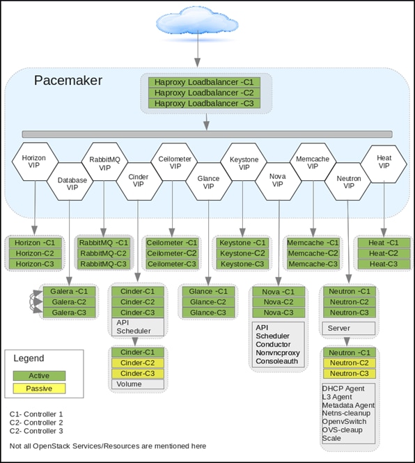
Other OpenStack Supporting Technologies
RabbitMQ
OpenStack services use enterprise messaging to communicate tasks and state changes between clients, service endpoints, service schedulers, and instances. RabbitMQ is open source message broker software that implements the Advanced Message Queuing Protocol (AMQP)
![]() RabbitMQ is default and recommended message broker service on Red Hat Enterprise Linux OpenStack Platform 6.0.
RabbitMQ is default and recommended message broker service on Red Hat Enterprise Linux OpenStack Platform 6.0.
MariaDB
A community developed fork of the MySQL relational database management system. This database stores most of the build-time and run-time state information for the cloud infrastructure including available instance types, networks, and the state of running instances in the compute fabric. Although OpenStack theoretically supports any SQL-Alchemy compliant database, MariaDB is the database shipped with Red Hat Enterprise Linux 7 and used by Red Hat Enterprise Linux OpenStack Platform 6.0 as default.
KVM
Kernel-based Virtual Machine (KVM) is a full virtualization solution for Linux on x86 and x86_64 hardware containing virtualization extensions for both Intel and AMD processors. It consists of a loadable kernel module that provides the core virtualization infrastructure. Red Hat Enterprise Linux OpenStack Platform Compute uses KVM as its underlying hypervisor to launch and control virtual machine instances.
OpenStack Networking
An overview of networking basics for OpenStack deployment are covered in this section
Modular Layer 2 (ML2) core
The Modular Layer 2 (ml2) plug-in is a framework that provides more flexibility in terms of providing simultaneous access to various networking technologies. Rather than rewrite code for huge monolithic core plugins associated with L2 agents like Open vSwitch, Linux Bridge etc., Mechanism Drivers can be written to the much simpler ML2 framework for these plugins.
ML2 Network Types:
· Flat: All instances reside on the same network, which can also be shared with the hosts. No VLAN tagging or other network segregation takes place.
· Local: Instances reside on the local compute host and are effectively isolated from any external networks.
· VLAN: Networking allows users to create multiple provider or tenant networks using VLAN IDs (802.1Q tagged) that correspond to VLANs present in the physical network. This allows instances to communicate with each other across the environment. They can also communicate with dedicated servers, firewalls, load balancers and other networking infrastructure on the same layer 2 VLAN.
· VXLAN: Virtual Extensible Local Area Network helps create a logical network for virtual machines across different networks. In other words one can create a Layer 2 network on top of layer 3 through encapsulation. The basic use case for VXLAN is to connect two or more Layer 3 networks and makes them look like they share the same Layer 2 domain. This allows for virtual machines to live in two disparate networks yet still operate as if they were attached to the same L2 thus enhancing scalability. The VXLAN networks are broken-down as segments and same IP address can exist across different segments. A combination of Machine Address Control (MAC) and VXLAN Network Identifier (VNI) makes each VM connection unique.
· GRE: Generic Routing Encapsulation (GRE) segmentation. A network layout in which tunnels are used to segregate and carry network traffic over individual tenant networks.
Hardware and Software Specifications
Below Table 2 and Table 3 describes solution components and the hardware and software releases used for solution validation.
![]() It is important to read Cisco and NetApp interoperability matrix and should be referenced to determine support for any specific implementation of FlexPod. For more information, please refer to the following links:
It is important to read Cisco and NetApp interoperability matrix and should be referenced to determine support for any specific implementation of FlexPod. For more information, please refer to the following links:
NetApp Interoperability Matrix Tool: http://support.netapp.com/matrix/
Cisco UCS Hardware and Software Interoperability Tool: http://www.cisco.com/web/techdoc/ucs/interoperability/matrix/matrix.html
Table 2 Validated Hardware Versions
| Layers |
Hardware |
Firmware Versions |
| Compute |
Cisco UCS Fabric Interconnects 6248UP |
2.2(3g) |
| Cisco UCS B200 M4 Server |
2.2(3g) |
|
| Cisco UCS Manager |
2.2(3g) |
|
| Cisco eNIC Driver |
2.1.1.75 |
|
| Network |
Cisco Nexus 9372 NX-OS |
6.1(2) I3(2) |
| Storage |
NetApp FAS8040 |
Dual Controller HA Pair |
| NetApp DS2246 |
SAS Disk Shelf |
|
| NetApp E-Series E5560 |
Dual Controller HA Pair |
Table 3 Validated Software Versions
| Layers |
Software |
Versions |
| Operating System |
Red Hat Enterprise Linux |
7.1 |
| OpenStack Platform |
Red Hat Enterprise Linux OpenStack Platform |
6.0 Juno Based |
|
|
Red Hat Enterprise Linux OpenStack Platform Installer |
6.0 |
| Software |
NetApp Cluster Data ONTAP |
8.3.0 |
| NetApp SANtricity OS |
8.20.08.00 |
|
| NetApp OnCommand System Manager |
8.3.0 |
|
| NetApp SANtricity Storage Manager |
11.20.0X00.0010 |
|
| Red Hat Enterprise Linux Cinder |
Drivers distributed with Red Hat Enterprise Linux OpenStack Platform 6.0 |
|
| Red Hat Enterprise Linux Swift |
Packagers distributed with Red Hat Enterprise Linux OpenStack Platform 6.0 |
|
| Cisco Nexus 1000v VSM for KVM |
5.2(1) SK3 (2.2a) |
|
| Cisco Nexus 1000v VEM module for each compute and controller node |
5.2(1) SK3 (2.2a) |
FlexPod with Red Hat Enterprise Linux OpenStack Platform Physical Topology
FlexPod with Red Hat Enterprise Linux OpenStack Platform 6.0 physical topology is made up of the following components. Figure 16 is the high-level diagram showing all the devices connected.
Table 4 List of Components
| Components |
Quantity |
Comments |
| Cisco UCS B200 M4 Blade Servers |
8 |
4 per Chassis |
| Cisco UCS 5108 Chassis |
2 |
|
| Cisco UCS 2104XP IO Modules |
4 |
2 Per Chassis |
| Cisco UCS 6248UP Fabric Interconnect |
2 |
|
| Cisco Nexus 9372PX |
2 |
|
| Cisco Nexus 1000v for KVM |
2 |
Virtual Appliance |
| NetApp FAS8040 System |
1 |
Two Nodes for HA |
| NetApp DS2246 with 24 900GB SAS drives |
1 |
|
| NetApp E5560 Storage System |
1 |
Dual Controllers for HA |
Figure 16 FlexPod with Red Hat Enterprise Linux OpenStack Platform Physical Topology
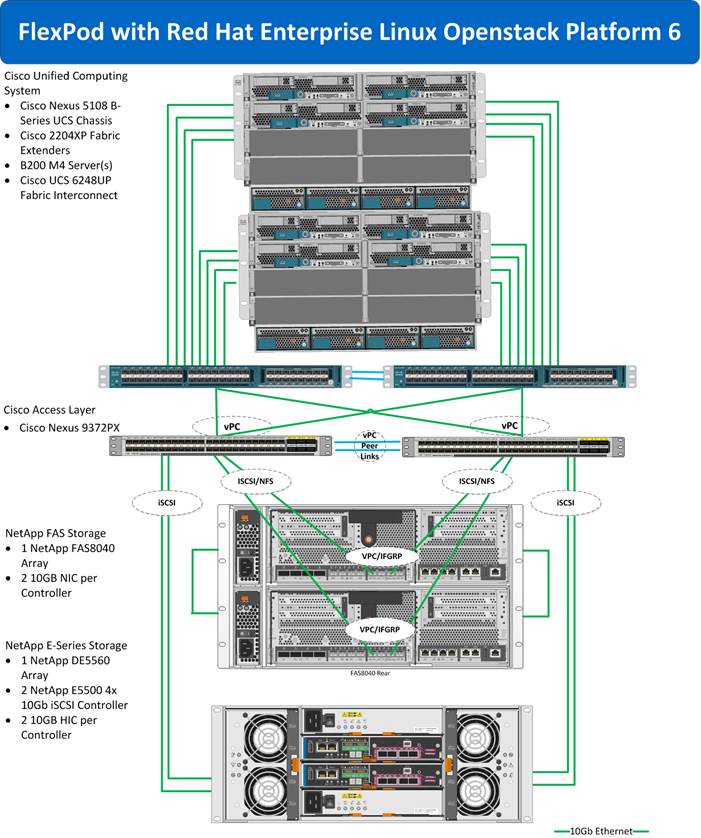
FlexPod with Red Hat Enterprise Linux OpenStack Platform Physical Design
Figure 17 demonstrates the FlexPod with Red Hat Enterprise Linux OpenStack Platform 6.0 compute, network, and storage design overview. The infrastructure is fully redundant and highly available end-to-end. The solution also incorporates NetApp technologies and feature to further enhance design efficiencies.
Figure 17 FlexPod with Red Hat Enterprise Linux OpenStack Platform Physical Design
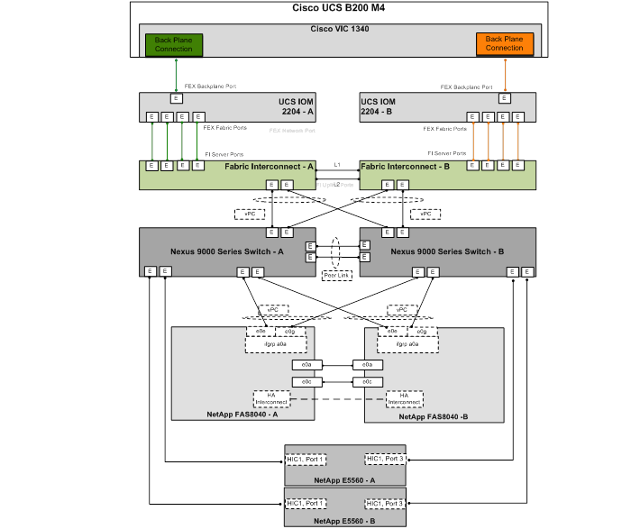
Cisco UCS Design
MLOM Virtual Interface Card (VIC)
FlexPod solution is typically validated using Cisco VIC 1240 or Cisco VIC 1280; with the addition of the Cisco UCS B200 M4 servers to FlexPod, VIC 1340 is validated on these new B200 M4 blade servers. Cisco VIC 1240 is a 4-port 10 Gigabit Ethernet, Fibre Channel over Ethernet (FCoE)-capable modular LAN on motherboard (mLOM) designed exclusively for the M3 generation of Cisco UCS B-Series Blade Servers. The Cisco VIC 1340, the next generation 2-port, 40 Gigabit Ethernet, Fibre Channel over Ethernet (FCoE)-capable modular LAN on motherboard (mLOM) mezzanine adapter is designed for both B200 M3 and M4 generation of Cisco UCS B-Series Blade Servers. When used in combination with an optional Port Expander, the Cisco UCS VIC 1340 capabilities can be expanded to eight ports of 10 Gigabit Ethernet with the use of Cisco UCS 2208XP fabric extender. VIC 1340 provides a redundant path to the fabric interconnect using hardware-based fabric failover. For more information, see: http://www.cisco.com/c/en/us/products/interfaces-modules/ucs-virtual-interface-card-1340/index.html
Cisco UCS Fabric Extender
Cisco UCS Fabric Extender also knows as IO Modules operates as a remote line card to the Fabric Interconnect. Each Cisco UCS chassis is equipped with a pair of Cisco UCS Fabric Extenders. The IO-Module has Network facing interfaces (NIF), which connect the IOM to the Fabric Interconnect, and host facing interfaces (HIF), which connect the IOM to the adapters on the blades. All interfaces are 10Gb DCE (Datacenter Ethernet). There are two different IOMs, each providing a different number of interfaces, 2208XP and 2204XP. Cisco UCS 2208XP has eight 10 Gigabit Ethernet, FCoE-capable ports that connect the blade chassis to the fabric interconnect. The Cisco UCS 2204 has four external ports with identical characteristics to connect to the fabric interconnect. Each Cisco UCS 2208XP has thirty-two 10 Gigabit Ethernet ports connected through the mid-plane to the eight half-width slots (4 per slot) in the chassis, while the 2204XP has 16 such ports (2 per slot).
Table 5 Fabric Extender Model Comparison
| Fabric Extender Module |
Network Facing Interface (NIF) |
Host Facing Interface (HIF) |
HIF/Slot |
| 2204XP |
4 |
16 |
2 |
| 2208XP |
8 |
32 |
4 |
Server Traffic Aggregation
Selection of the FEX, VIC and Mezzanine cards plays an important role in determining the aggregate traffic throughput to and from a server. Figure 18 shows an overview of backplane connectivity of Cisco VIC 1340 architecture. The number of KR lanes indicates the 10GbE paths available to the chassis and therefore blades. As shown in Figure 18, depending on the models of I/O modules and VICs, traffic aggregation differs. 2204XP enables 2 KR lanes per half-width blade slot whereas the 2208XP enables all four. Similarly number of KR lanes varies based on selection of VIC 1240/1340, VIC 1240/1340 with Port Expander and VIC 1280/1380.
Figure 18 Cisco UCS VIC 1340 Architecture
|
|
|
Validated I/O Components and Servers
In this FlexPod design, validated IO components are:
Table 6 I/O Components
| Server |
VIC |
FEX |
| B200M4 |
1340 |
2204 |
![]() In FlexPod with Red Hat Enterprise Linux OpenStack Platform 6.0, Cisco UCS B200 M4 servers have been validated with Cisco VIC 1340 and Cisco 2204XP Fabric Extender.
In FlexPod with Red Hat Enterprise Linux OpenStack Platform 6.0, Cisco UCS B200 M4 servers have been validated with Cisco VIC 1340 and Cisco 2204XP Fabric Extender.
Fabric Failover for Ethernet: Highly Available vNIC
Each adapter in Cisco UCS is a dual-port adapter that connects to both fabrics (A and B). The two fabrics in Cisco UCS provide failover protection in the event of planned or unplanned component downtime in one of the fabrics. Typically, host software such as NIC teaming for Ethernet or multipath I/O (MPIO) for Fibre Channel provides failover across the two fabrics (Figure 19). A vNIC in Cisco UCS is a host-presented PCI device that is centrally managed by Cisco UCS Manager. The fabric-based failover feature, which you enable by selecting the high-availability vNIC option in the service profile definition, allows network interface virtualization (NIV)-capable adapters and the fabric interconnects to provide active-standby failover for Ethernet vNICs without any NIC-teaming software on the host. For unicast traffic failover, the fabric interconnect in the new path sends Gratuitous Address Resolution Protocols (GARPs). This process refreshes the forwarding tables on the upstream switches.
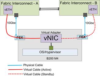
For multicast traffic, the new active fabric interconnect sends an Internet Group Management Protocol (IGMP) Global Leave message to the upstream multicast router. The upstream multicast router responds by sending an IGMP query that is flooded to all vNICs. The host OS responds to these IGMP queries by rejoining all relevant multicast groups. This process forces the hosts to refresh the multicast state in the network in a timely manner.
Cisco UCS fabric failover is an important feature because it reduces the complexity of defining NIC teaming software for failover on the host. It does this transparently in the fabric based on the network property that is defined in the service profile.
Cisco UCS Physical Connectivity to Nexus 9000
Cisco UCS Fabric Interconnects are connected with Nexus 9372 as shown in the Figure 20. It is configured with two port-channels, one from each Cisco UCS Fabric Interconnect to Cisco Nexus 9372. These port channels carry all the storage and data traffic. In this validated design, two uplinks from each fabric interconnect to the leaf switches have been utilized for an aggregate bandwidth of 40Gbe (4x10Gbe). However, the number of links can be increased based on the customer’s throughput requirements.
Figure 20 Cisco UCS Physical Connectivity to Cisco Nexus 9372PX
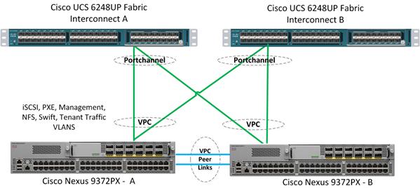
Chassis/FEX discovery
Cisco Unified Computing System can be configured to discover a chassis using Discrete Mode or the Port-Channel mode (Figure 21). In Discrete Mode each FEX KR connection and therefore server connection is tied or pinned to a network fabric connection homed to a port on the Fabric Interconnect. In the presence of a failure on the external "link" all KR connections are disabled within the FEX I/O module. In Port-Channel mode, the failure of a network fabric link allows for redistribution of flows across the remaining port channel members. Port-Channel mode therefore is less disruptive to the fabric and hence recommended in the FlexPod designs.
Figure 21 Chassis Discovery Policy – Discrete vs. Port Channel
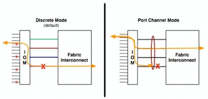
Cisco UCS QoS and Jumbo Frames
FlexPod accommodates a myriad of traffic types (iSCSI, NFS, VM traffic, etc.) and is capable of absorbing traffic spikes and protect against traffic loss. Cisco Unified Computing System and Nexus QoS system classes and policies deliver this functionality. In this validation effort the FlexPod was configured to support jumbo frames with an MTU size of 9000. Enabling jumbo frames allows the FlexPod environment to optimize throughput between devices while simultaneously reducing the consumption of CPU resources.
![]() When setting jumbo frames, it is mandatory that MTU settings are applied uniformly across the stack to prevent packet drops and adverse performance.
When setting jumbo frames, it is mandatory that MTU settings are applied uniformly across the stack to prevent packet drops and adverse performance.
Cisco Nexus 9000 Series Modes of Operation
The Cisco Nexus 9000 family of switches also supports two modes of operation: NxOS standalone mode and Application Centric Infrastructure (ACI) fabric mode. In standalone mode, the switch performs as a typical Cisco Nexus switch with increased port density, low latency and 40Gbe connectivity. In fabric mode, the administrator can take advantage of Cisco ACI. The Cisco Nexus 9000 stand-alone mode FlexPod design consists of a pair of Cisco Nexus 9000 Series top of rack switches. When leveraging ACI fabric mode, the Cisco Nexus 9500 and 9300 switches are deployed in a spine-leaf architecture. Although the reference architecture covered in this document does not leverage ACI, it lays the foundation for customers to migrate to Cisco ACI by leveraging the Cisco Nexus 9000 switches. Cisco ACI is a holistic architecture with centralized automation and policy-driven application profiles. Cisco ACI delivers software flexibility with the scalability of hardware performance. Key characteristics of ACI include:
· Simplified automation by an application-driven policy model
· Centralized visibility with real-time, application health monitoring
· Open software flexibility for DevOps teams and ecosystem partner integration
· Scalable performance and multi-tenancy in hardware
The future of networking with Cisco ACI is about providing a network that is deployed, monitored, and managed in a fashion that supports DevOps and rapid application change. Cisco ACI does so through the reduction of complexity and a common policy framework that can automate provisioning and managing of resources.
![]() In FlexPod with Red Hat Enterprise Linux OpenStack Platform 6.0, a pair of Cisco Nexus 9000 series switch is used in standalone NX-OS mode
In FlexPod with Red Hat Enterprise Linux OpenStack Platform 6.0, a pair of Cisco Nexus 9000 series switch is used in standalone NX-OS mode
Cisco Nexus 9000 Standalone Mode Design
In this validated architecture, a pair of Cisco Nexus 9000 is deployed in NxOS standalone mode. Cisco Nexus 9000 related best practices are used in the validation of the FlexPod with Red Hat Enterprise Linux OpenStack Platform 6.0 architecture. It is summarized as listed below:
· Cisco Nexus 9000 features enabled
— Link Aggregation Control Protocol (LACP part of 802.3ad)
— Cisco Virtual Port Channeling (vPC) for link and device resiliency
— Enable Cisco Discovery Protocol (CDP) for infrastructure visibility and troubleshooting
— Interface VLAN for configuring the Layer-3 SVI interfaces for the VLANs designated for forwarding.
· vPC considerations
— Define a unique domain ID
— Set the priority of the intended vPC primary switch lower than the secondary (default priority is 32768)
— Establish peer keepalive connectivity. It is recommended to use the out-of-band management network (mgmt0) or a dedicated switched virtual interface (SVI)
— Enable vPC auto-recovery feature
— Enable peer-gateway. Peer-gateway allows a vPC switch to act as the active gateway for packets that are addressed to the router MAC address of the vPC peer allowing vPC peers to forward traffic
— Enable IP arp synchronization to optimize convergence across the vPC peer link. Note: Cisco Fabric Services over Ethernet (CFSoE) is responsible for synchronization of configuration, Spanning Tree, MAC and VLAN information, which removes the requirement for explicit configuration. The service is enabled by default.
— A minimum of two 10 Gigabit Ethernet connections are required for vPC
— All port channels should be configured in LACP active mode
· Spanning tree considerations
— The spanning tree priority was not modified. Peer-switch (part of vPC configuration) is enabled which allows both switches to act as root for the VLANs
— Loopguard is disabled by default
— BPDU guard and filtering are enabled by default
— Bridge assurance is only enabled on the vPC Peer Link.
— Ports facing the NetApp storage controller and UCS are defined as "edge" trunk ports
For configuration details, see the Cisco Nexus 9000 series switches configuration guide: http://www.cisco.com/c/en/us/support/switches/nexus-9000-series-switches/products-installation-andconfiguration-guides-list.html
IP Based Storage and Boot from iSCSI
FlexPod Cisco Nexus 9000 standalone design is an end-to-end IP-Based storage solution that supports SAN access using iSCSI. The solution provides a 10GbE-enabled, 40G capable, fabric defined by Ethernet uplinks from the Cisco UCS Fabric Interconnects and NetApp storage devices connected to the Cisco Nexus switches, as The Cisco Nexus 9000 standalone design does not employ a dedicated SAN switching environment and requires no direct Fibre Channel connectivity as iSCSI is the SAN protocol leveraged.
There are no local disks in this architecture. Red Hat Enterprise Linux 7.1 is deployed on boot LUNs provided by NetApp FAS through the iSCSI protocol.
Link Aggregation and Virtual Port Channel
As illustrated in Figure 23, link aggregation technologies play an important role, providing improved aggregate bandwidth and link resiliency across the solution stack. The NetApp storage controllers, Cisco Unified Computing System, and Cisco Nexus 9000 platforms support active port channeling using 802.3ad standard Link Aggregation Control Protocol (LACP). Port channeling is a link aggregation technique offering link fault tolerance and traffic distribution (load balancing) for improved aggregate bandwidth across member ports. In addition, the Cisco Nexus 9000 series features virtual PortChannel (vPC) capabilities. vPC allows links that are physically connected to two different Cisco Nexus 9000 Series devices to appear as a single "logical" port channel to a third device, essentially offering device fault tolerance. vPC addresses aggregate bandwidth, link, and device resiliency. The Cisco UCS Fabric Interconnects and NetApp FAS controllers benefit from the Cisco Nexus vPC abstraction, gaining link and device resiliency as well as full utilization of a non-blocking Ethernet fabric.
This dedicated uplink design leverages IP-based storage-capable NetApp FAS controllers. From a storage traffic perspective, both standard LACP and the Cisco vPC link aggregation technologies play an important role in the FlexPod distinct uplink design. Figure 23 illustrates the use of dedicated 10GbE uplinks between the Cisco UCS Fabric Interconnects and the Cisco Nexus 9000 unified switches. vPC links between the Cisco Nexus 9000 and the NetApp storage controllers' 10GbE provide a robust connection between host and storage.
vPC Peer Link
vPC requires a "peer link" which is documented as port channel 10 Figure 23. In addition to the vPC peer-link, vPC peer keepalive link is a required component of a vPC configuration. The peer keepalive link allows each vPC enabled switch to monitor the health of its peer. This link accelerates convergence and reduces the occurrence of split-brain scenarios.
Cisco Nexus 1000v for KVM Solution Design
In FlexPod with Red Hat Enterprise Linux OpenStack Platform 6.0, Cisco Nexus 1000v for KVM is deployed with OpenStack in high-availability mode. In HA mode, two VSM module in active/standby are deployed in two controller hosts. Figure 22 illustrates the deployment methodology.
Figure 22 Cisco Nexus 1000v Logical Topology
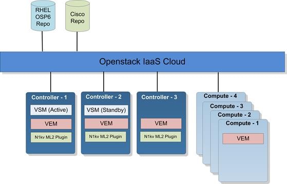
· Cisco Nexus 1000v is deployed using Red Hat Enterprise Linux OpenStack Platform installer by specifying Cisco repo, which is an external repo for access to Cisco Nexus 1000v packages. It includes Cisco Nexus 1000v VSM and VEM packages along with Cisco Nexus 1000v ML2 driver.
· VSM is deployed as a virtual appliance on KVM hypervisor in two of the three controllers in active/standby configuration.
· VEM module is deployed in all controllers and compute hosts.
· Neutron Nexus 1000v ML2 driver is deployed in all controller nodes through host groups in Red Hat Enterprise Linux OpenStack Platform installer.
NetApp FAS Solution Design
This Cisco Validated Design leverages NetApp FAS8040 controllers, deployed with NetApp Clustered Data ONTAP 8.3.
In the NetApp Clustered Data ONTAP architecture, all data is accessed through SVMs. It is possible to have a single SVM that represents the resources of the entire cluster, or multiple SVMs that are assigned specific subsets of cluster resources for given applications, tenants or workloads. The SVM can serve as the storage basis for each tenant with Red Hat Enterprise Linux 7 hosts booted from SAN by using iSCSI and for hosting data presented as NFS traffic to the hypervisor hosts.
Network and Storage Physical Connectivity
NetApp FAS8000 storage controllers are configured with two port channels connected to the Cisco Nexus 9000 switches as shown in Figure 23. These port channels carry all of the ingress and egress data traffic for the NetApp controllers. This validated design uses two physical ports from each NetApp controller, configured as an LACP interface group (ifgrp). The number of ports used can be easily modified depending on the application requirements.
This solution makes use of the following fundamental connections or network types on the NetApp FAS8040:
· Cluster interconnect. A dedicated high-speed, low-latency, private network, used for communication between nodes. This network can be implemented through the deployment of a switchless cluster or by leveraging dedicated cluster interconnect switches.
· Management network. A network used for the administration of nodes, the cluster, and SVMs.
· Data network. A network used by clients to access data.
· Ports. A physical port such as e0a or e1a, a logical port such as a virtual LAN (VLAN), or an interface group.
· Interface groups. - A collection of physical ports that create one logical port. The NetApp interface group is a link aggregation technology that can be deployed in single (active/passive), multiple ("always on"), or dynamic (active LACP) mode.
This validation uses two storage nodes configured as a two-node storage failover-pair through an HA interconnect direct connection. This FlexPod design uses the following port and interface assignments:
· Ethernet ports e0e and e0g on each node are members of a multimode LACP interface group (a0a) for Ethernet data. This design leverages an interface group that has LIFs associated with it on 802.1Q VLAN tagged interfaces to support NFS and iSCSI traffic.
· Ports e0M on each node support a LIF dedicated to node management.
· Port e0M supports cluster management data traffic through the cluster management LIF. This port and LIF allow for administration of the cluster from the failover port and LIF if necessary.
· Ports e0a and e0c are cluster interconnect ports for cluster traffic. These ports are connected directly to the other node’s corresponding physical port (e0a à e0a, and e0c à e0c).
Figure 23 Network and Storage Physical Connectivity for NetApp FAS8040
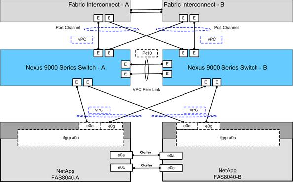
![]() If an expansion is required beyond two nodes, a cluster interconnect network can be implemented non-disruptively by adding a Cisco Nexus 5596 pair as cluster interconnect switches. For more information, see: Migrating to a two-node switched cluster with Cisco® cluster switches.
If an expansion is required beyond two nodes, a cluster interconnect network can be implemented non-disruptively by adding a Cisco Nexus 5596 pair as cluster interconnect switches. For more information, see: Migrating to a two-node switched cluster with Cisco® cluster switches.
Clustered Data ONTAP Logical Topology Diagram
Figure 24 details the logical configuration of the NetApp Clustered Data ONTAP environment used for validation of the FlexPod solution. The physical cluster consists of two NetApp storage controllers (nodes) configured as an HA pair with a switchless cluster.
LIFs used for Ethernet traffic are assigned specific Ethernet-based details such as IP addresses and iSCSI-qualified names and then are associated with a specific physical port capable of supporting Ethernet traffic. NAS LIFs can be non-disruptively migrated to any other physical network port throughout the entire cluster at any time, either manually or automatically by using policies.
Figure 24 NetApp Data ONTAP Logical Topology Layout
Clustered Data ONTAP Configuration for OpenStack
This solution defines two SVMs to own and export the data necessary to run the Red Hat Enterprise Linux OpenStack Platform infrastructure. First, we create an Infrastructure SVM. This SVM is responsible for containing the data that allows our Cisco UCS servers to boot through an iSCSI volume and hold necessary infrastructure related data for the resulting OpenStack cloud. No virtual machine or client data is housed in this special SVM in order to separate tenant data from infrastructure related data. It has the following flexible volumes:
· Root volume. A flexible volume that contains the root of the SVM namespace.
· Root volume load-sharing mirrors. Mirrored volume of the root volume to accelerate read throughput. In this instance, they are labeled rootvol_m01 and rootvol_m02.
· Boot volume. A flexible volume that contains Red Hat Enterprise Linux 7 boot LUNs for each UCS server. These boot LUNs are exported through iSCSI.
Second, we create an OpenStack tenant SVM. This SVM is responsible for containing the Cinder volumes that represent client instances (virtual machines) that are used to store persistent data for application workloads in the cloud. It has the following flexible volumes:
· Root volume. A flexible volume that contains the root of the SVM namespace.
· Root volume load-sharing mirrors. Mirrored volume of the root volume to accelerate read throughput. In this instance, they are labeled rootvol_m01 and rootvol_m02.
· archived_data volume. A flexible volume that has NetApp deduplication, thin provisioning, and compression enabled at the volume level. It is used as the infrastructure NFS volume for a tenant that wishes to use NetApp space-efficiency technology for any resulting Cinder volumes.
· glance volume. A flexible volume that has NetApp deduplication enabled at the volume level. It is used as the image repository for the OpenStack Glance image service to store template images for provisioning into eventual Cinder volumes.
· cinder1 volume. A flexible volume that has NetApp thick provisioning enabled at the volume level.
· cinder2 volume. An additional flexible volume that has NetApp thick provisioning enabled at the volume level. This represents additional storage for OpenStack cinder volumes.
· cinder3 volume. An additional flexible volume that has NetApp thick provisioning enabled at the volume level. This represents additional storage for OpenStack cinder volumes..
![]() Additional volumes can be created in order to accommodate customer or workload requirements. The examples described previously in which different flexible volumes accommodate instance Cinder volumes are only used as an example to illustrate the Cinder volume-type functionalities “Extra-Specs” able to be leveraged by the NetApp Cinder driver. NetApp refers to this functionality as a Storage Service Catalog so that NetApp technology is exposed using volume types in Cinder.
Additional volumes can be created in order to accommodate customer or workload requirements. The examples described previously in which different flexible volumes accommodate instance Cinder volumes are only used as an example to illustrate the Cinder volume-type functionalities “Extra-Specs” able to be leveraged by the NetApp Cinder driver. NetApp refers to this functionality as a Storage Service Catalog so that NetApp technology is exposed using volume types in Cinder.
NetApp recommends a minimum of four flexible volumes for OpenStack cinder volume creation. This provides additional scalability and higher performance for the overall deployment.
The NFS volumes are mounted on each Red Hat Enterprise Linux 7 host in the environment and are provided by NetApp clustered Data ONTAP through NFS over the 10GbE network. Each node has an NFS LIF in order to accommodate features of parallel NFS.
The SVM has a minimum of one LIF per protocol per node to maintain volume availability across the cluster nodes. The LIFs use failover groups, which are network polices defining the ports or interface groups available to support a single LIF migration or a group of LIFs migrating within or across nodes in a cluster. Multiple LIFs may be associated with a network port or interface group. In addition to failover groups, the clustered Data ONTAP system uses failover policies. Failover polices define the order in which the ports in the failover group are prioritized. Failover policies define migration policy in the event of port failures, port recoveries, or user-initiated requests.
The most basic possible storage failover scenarios in this cluster are as follows:
· Node A fails, and Node B takes over Node A's storage.
· Node B fails, and Node A takes over Node B's storage.
The remaining node network connectivity failures are addressed through the redundant port, interface groups, and logical interface abstractions afforded by the clustered Data ONTAP system.
Storage Virtual Machine Layout
Figure 25 highlights the storage topology showing SVM and associated LIFs. There are two storage nodes and the SVM's are layered across both controller nodes. Each SVM has its own LIFs configured to support SVM-specific storage protocols.
Figure 25 Storage Virtual Machine Layout
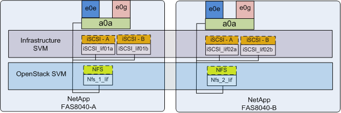
The Infrastructure SVM is providing iSCSI boot LUNs to all the hosts for boot from SAN, and the OpenStack SVM is providing Cinder and Glance services.
NetApp E-Series Storage Design
This Cisco Validated Design leverages NetApp E5500 Controllers, deployed with SANtricity OS 8.20.08.
In the SANtricity OS architecture, all data is accessed through individual LUNs exposed to hosts that are backed by DDPs through one of the following - Fibre Channel Protocol (FCP), iSCSI, SAS, or Infiniband. It is a NetApp best practice to have one DDP per host that communicates with the storage system. The OpenStack Object Storage Service (Swift) is the exclusive consumer of the storage provided by the NetApp E5560.
Network and Storage Physical Connectivity
The NetApp E5500 controllers are configured with (4) individual 10Gb connections to the Cisco Nexus 9000 switches as shown in Figure 26. These interfaces carry all the ingress and egress data traffic for the NetApp controllers. This validated design uses two physical ports (called host interface cards, or HICs) from each NetApp E5500 controller for a total of four ports. The number of ports used can be easily modified depending on the application requirements.
This solution makes use of the following fundamental connections or network types on the NetApp E5500:
· Management network. A network used for the administration of the controllers through SANtricity.
· Data network. A network used by clients to access Swift related data.
· Ports. A physical port such as Controller A, HIC1, Port 1.
This validation uses two NetApp E5500 controllers configured as a High Availability pair. This FlexPod design uses the following port and interface assignments:
· Four HIC ports are used for Ethernet data across both controllers. They are Controller A, HIC1, Port 1, Controller A, HIC1, Port3, Controller B, HIC1, Port1, and Controller B, HIC1, Port3. This design leverages ports that not only encompass both controllers, but different ASICs on the controllers themselves.
· One of the Ethernet management ports on each controller to support management operations using the SANtricity Storage Manager application.
Figure 26 Network and Storage Physical Connectivity for NetApp E5560
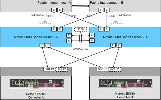
SANtricity OS Configuration for OpenStack
This solution defines three DDPs as the overarching abstraction of the physical storage resources to own and export the data necessary to house the OpenStack Object Storage Service (Swift).
From within each DDP, three volumes are created that house the following:
· Account Data. Account services manage accounts defined with the object storage service.
· Container Data. Container services manage a mapping of containers (for example, folders) within the object store service.
· Object Data. Object services manage actual objects (for example, files) on the storage nodes.
Typically, each Swift node handles account, container, and object services. In this solution, each controller system hosts account, container, object, and proxy services. HAproxy and Pacemaker are configured to monitor availability and keep necessary Swift services active and online for high availability.
Each DDP’s volumes are exposed through iSCSI LUNs to the controller systems through the SANtricity Storage Manager application. The Controller systems are then configured for network access on both an iSCSI-A and iSCSI-B network, which allows them all to log into the E5560 system through the iSCSI protocol and mount their own LUNs and format them with the XFS file system to be used by Swift daemons and services. Swift itself is then deployed and configured by the administrator and is then available for usage by users and tenants.
Cisco UCS and NetApp Storage OpenStack Deployment Topology
Red Hat Enterprise Linux installer deploys OpenStack services to hosts and maps it to the selected roles such as controllers and compute hosts. The Figure 27 outlines the OpenStack deployment topology and different networks used in this solution.
Figure 27 OpenStack Deployment Topology
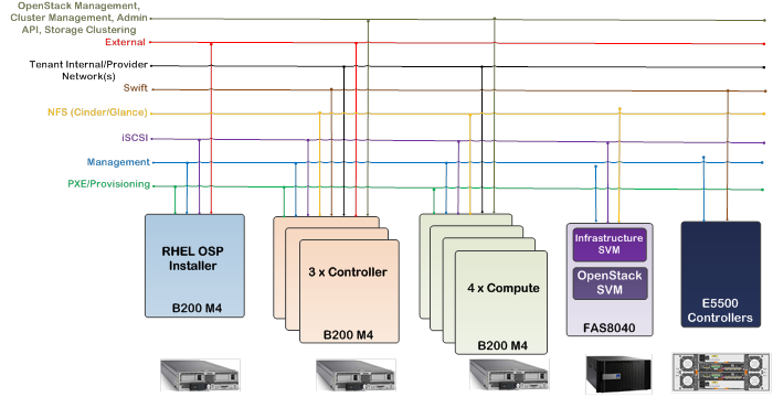
Below are the details of the above mentioned networks:
· iSCSI network provides boot LUN to all the hosts to boot from SAN for stateless booting(no local drive necessary). There are multiple paths to the boot LUN.
· PXE/Provisioning network is used by Red Hat Enterprise Linux OpenStack Platform installer for provisioning and configuring controller and compute hosts. Installer uses this network to boot hosts using PXE it is also used for deploying and configuring hosts.
· In this validated design, separate dedicated network is used to carry OpenStack Management, Cluster Management, Admin API, and Storage Clustering traffic. OpenStack admin and OpenStack private virtual IP addresses will be created on this network. This network must be assigned to all hosts in the deployment. Details of these OpenStack networks will be covered in the later sections.
· Management network is used for host management, storage devices, and it also carries OpenStack public API traffic.
· NFS network carries traffic for Cinder and Glance. NetApp FAS8040 is providing Cinder volumes to guest instances and so is the Glance image repository.
· Swift carries OpenStack swift storage traffic. NetApp E5560 is providing Swift storage.
· Tenant network carries tenant’s VM traffic and provides traffic segmentation among tenants.
· External network represents a public network. Installer node uses this network during the deployment process. This network also provides external connectivity to tenant’s VMs.
![]() PXE/Provisioning is the default subnet in Red Hat Enterprise Linux OpenStack Platform Installer. It is recommended NOT to share this network with any other traffic types for production grade deployment. It is recommended to separate different traffic types through different subnets/VLANs.
PXE/Provisioning is the default subnet in Red Hat Enterprise Linux OpenStack Platform Installer. It is recommended NOT to share this network with any other traffic types for production grade deployment. It is recommended to separate different traffic types through different subnets/VLANs.
Hosts Roles and OpenStack Service Placement in Cisco UCS
Red Hat Enterprise Linux Platform is installed on Cisco UCS B200 M4 servers based on FlexPod topology shown in Figure 16. Red Hat Enterprise Linux OpenStack Platform installer is using two roles in the solution:
Controller: Provide key services such MySQL database for storing data about the overall environment, message queue, horizon, cinder, keystone, and etc.
Compute: Hosts under compute role act as a hypervisor for guest virtual machines. Additional compute nodes can be added as needed within the environment at any time by assigning the hosts to this deployment role and repeating the provisioning process. Installer will install the new hosts ignoring all that have been deployed before.
As mentioned in Figure 27, one host is dedicated to run Red Hat Enterprise Linux OpenStack Platform installer; three nodes are used for running OpenStack controller nodes, and four nodes for OpenStack compute. All OpenStack nodes are running Red Hat Enterprise Linux 7.1 as shown in Table 7.
Table 7 OpenStack Service Placement
| Host |
Servers |
Role |
Services |
Type |
| Red Hat Enterprise Linux 7.1 (1) |
B200 M4 |
Admin Node |
Red Hat Enterprise Linux OpenStack Platform Installer |
|
| Red Hat Enterprise Linux 7.1 (3) |
B200 M4 |
Controller |
Horizon, Keystone, Glance-API, Glance registry, Cinder-API, Swift, Nova-API, Nova-Schedular, Nova-Conductor, Neutron-Server, Heat, Ceilometer, Ml2-Plugin-agent, Neutron-L2-agent, Neutron L3-agent, Neutron-DHCP-agent, RabbitMQ, MariaDB, Galera, HAProxy, Pacemaker cluster, Nexus 1000v VSM and VEM, and more |
HA – Clone Nexus 1000v VSM pair in two of the three controller nodes. Two controllers in Chassis 1 and one controller in chassis 2
|
| Red Hat Enterprise Linux 7.1 (4) |
B200 M4 |
Compute |
Nova-compute, Neutron L2 agent, Ceilometer-agent, Cisco Nexus 1000v VEM, and more |
Single Server Node (HA Proxy and pacemaker service does not run in compute node) |
Figure 28 Hosts Roles and OpenStack Service Placement
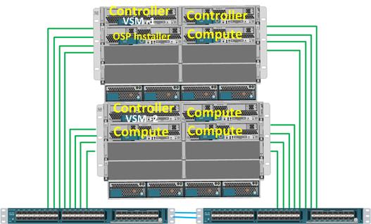
By design a single Cisco UCS Chassis is highly redundant with redundant hot-swappable power supplies and fans and hot pluggable fabric extenders and servers. However, for extra level of redundancy at the OpenStack controller level, two controllers are placed in one chassis and one controller is placed in another chassis. Furthermore, one of the two Cisco Nexus 1000v Virtual Supervisor Module (VSM) is placed in one chassis in the controller host and the other VSM module is place in the second chassis controller host (Figure 28). This allows operational efficiency and resiliency.
![]() More compute nodes can be added depending on the requirements, if additional scale is desired.
More compute nodes can be added depending on the requirements, if additional scale is desired.
Red Hat Enterprise Linux OpenStack Platform Installer Network Traffic Types
Red Hat Enterprise Linux OpenStack Platform Installer uses the following network traffic types for deployment. All of the below network traffic types except “external” and “tenant” get assigned to the “default” traffic type. At a minimum, besides default, two additional subnets are ideal for “external” and “tenant” networks. If there is capacity to add additional network interfaces, the traffic types can be further isolated by creating additional subnets.
· Provisioning/PXE - Used for PXE/provisioning of hosts. This one is set to the default subnet in foreman which is mapped to the boot/PXE interface on the hosts and cannot be changed. Foreman manages DHCP for this network.
· External - Used for external connectivity/bridges for instances. The IP addresses on this network should be reachable outside the intranet.
· Tenant - For tenant network traffic internally among virtual Instances.
· Management - Private API for services. Provides internal communication between OpenStack components. IP addresses on this network should be reachable only within the datacenter.
· Public API - Sets up access to the RESTFUL API, and the Horizon GUI, exposes all OpenStack APIs, including the Networking API, to tenants. IP addresses on this network should be reachable by anyone on the intranet.
· Admin API – For admin access for various services.
· Cluster Management – Used by Pacemaker and Galera for cluster communications.
· Storage – For connectivity between Controller, Compute, and storage nodes for storage traffic.
Table 8 describes the network traffic types used in each host group. Ideally network separation is a good practice where possible. This helps in handling performance, scalability and isolation requirements.
| Network Traffic Type |
Controller |
Compute |
Red Hat Enterprise Linux OpenStack Platform Installer |
| Provisioning |
√ |
√ |
√ |
| Admin API |
√ |
|
|
| Management |
√ |
√ |
|
| External |
√ |
√ |
√ |
| Tenant |
√ |
√ |
|
| Public API |
√ |
√ |
|
| Storage |
√ |
√ |
|
| Storage Clustering |
|
|
|
| Cluster Management |
√ |
|
|
In FlexPod with Red Hat Enterprise Linux OpenStack Platform 6.0 design,
· Public API and OpenStack Management, Cluster Management, Admin API, and Storage Clustering network is separated for traffic isolation, security, and enhanced performance.
· In this FlexPod design, OpenStack Management, Cluster Management, Admin API, and Storage Clustering traffic share the same subnet.
· NetApp NFS Storage traffic for Cinder and Glance OpenStack services is on a dedicated network.
· PXE network is created for setting up Red Hat Enterprise Linux OpenStack Platform controller and compute nodes. This network is used for discovering hosts by the installer. PXE is a dedicated network and is not shared by any other network types in the design. This network is only reachable within the datacenter.
· External network is used for outside world connectivity by the OpenStack instances and also by the installer node during the provisioning process of controller and compute hosts.
· Tenant networks are created for instances to communicate with each other across the stack and provides VLAN segmentation among tenant’s instances.
VLAN Configuration
Network data within the cluster is segmented logically using VLANs. The entire range of VLANs assigned for the topology as needed to be configured ahead of time on both the Cisco Nexus 9000 Series switch as well as the UCS Fabric Interconnect. In this FlexPod with Red Hat Enterprise Linux OpenStack Platform design, VLANs are divided into: management, PXE, MCAS (OpenStack Management, Cluster Management, Admin API, and Storage Clustering), NFS, iSCSI, Swift, external or public, provider, and tenants. Port channels connecting Cisco Nexus 9000 Series to Cisco UCS Fabric Interconnect are configured to allow those VLANs. When configuring NetApp FAS8040 for Cisco Nexus 9000 Series connectivity, port channel connecting Nexus 9000 to NetApp FAS is configured with iSCSI and NFS VLANs.
Cisco VIC 1340 allows for the creation of virtual NICs (vNIC) presented to the operating system and also provides dynamic failover for redundancy. These VLANs are then subsequently added to appropriate vNICs of Red Hat Enterprise Linux OpenStack Platform installer, controller, and compute hosts as shown in Figure 29.
OpenStack storage specific VLANs (NFS and Swift), OpenStack Management, Cluster Management, Admin API, and Storage Clustering VLAN, and tenant data VLANs are not needed for the installer host. Installer host has management, PXE, iSCSI, and external VLANs
![]() Tenant VM data VLANs are pre-provisioned in Cisco Nexus 9000 and Fabric Interconnect.
Tenant VM data VLANs are pre-provisioned in Cisco Nexus 9000 and Fabric Interconnect.
Figure 29 Logical Topology with vNICs
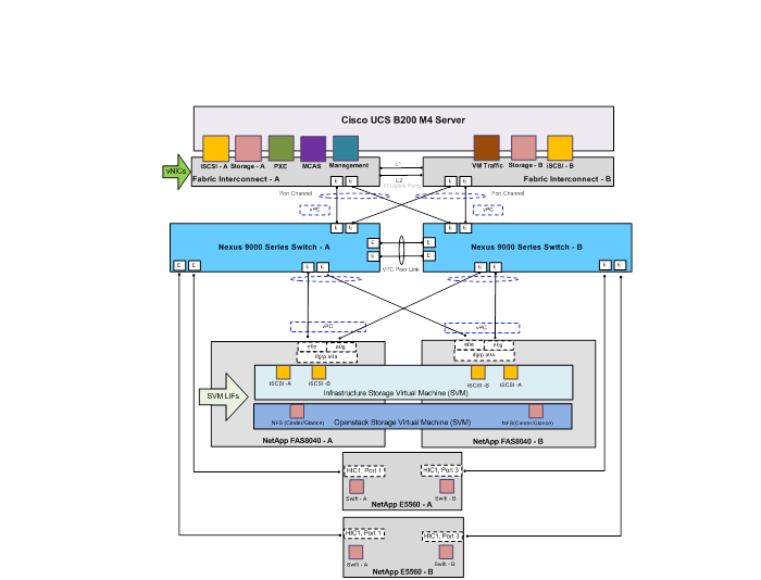
FlexPod is the optimal shared infrastructure foundation to deploy a variety of IT workloads. It is built on leading computing, networking, storage, and infrastructure software components. FlexPod Datacenter with Red Hat Enterprise Linux OpenStack Platform 6.0 is a single platform built from unified computing, fabric, and storage technologies from Cisco and NetApp that is both flexible and scalable. FlexPod with Red Hat Enterprise Linux OpenStack Platform 6.0 validated design provides production grade OpenStack deployment with ease supported by industry leaders to meet the unique needs of your business. With this solution, we are responding to the increased customer demand for OpenStack on validated converged infrastructure.
To summarize, these are the major benefits of implementing FlexPod with Red Hat Enterprise Linux OpenStack Platform 6.0:
· Converged Infrastructure based on Cisco Unified Datacenter
· Investment protection in high density, flexible and high performance datacenter environments.
· Non-disruptive scale up or out infrastructure.
· Highly available and supported OpenStack platform on Red Hat optimized distribution.
· End to end hardware level redundancy using Cisco UCS, Cisco Nexus switches, and NetApp high availability features.
· Pre-validated design based on best practices to achieve timely, repeatable, and consistent deployments.
Muhammad Afzal, Architect Engineering, Cisco UCS Datacenter Solutions Engineering, Cisco Systems Inc.
Muhammad Afzal is an Engineering Architect at Cisco Systems in Cisco UCS Datacenter solution engineering. He is currently responsible for producing and designing validated converged architectures while working collaboratively with product partners. Previously, Afzal had been a lead architect for various cloud and datacenter solutions including UCSO in Solution Development Unit at Cisco. Prior to this, Afzal has been a Solutions Architect in Cisco’s Advanced Services group, where he worked closely with Cisco's large enterprise and service provider customers delivering datacenter and cloud solutions. Afzal holds an MBA in finance and a BS in computer engineering.
Dave Cain, Reference Architect, Converged Infrastructure Engineering, NetApp
Dave is a Reference Architect and Technical Marketing Engineer with NetApp’s Converged Infrastructure Engineering organization. He focuses on producing validated reference architectures that promote the benefits of NetApp storage and software into datacenter and cloud environments. Prior to joining NetApp, he spent 10 years in various roles at IBM focused on Network, Storage, and Virtualization IT infrastructure. Dave holds a Bachelor of Science degree in Computer Science from North Carolina State University. He coauthored Five IBM Redbooks publications, and holds two US patents and various invention disclosures in the computer networking field.
Tushar Katarki, Integration Architect, Red Hat
Tushar Katarki is a technology professional with experience in datacenter, cloud and storage technologies. He is currently an Integration Architect at Red Hat driving cross product architecture and integration across Red Hat and partner products. Prior to the current role, Tushar has been a product manager and a developer at Red Hat, Oracle (Sun Microsystems), Polycom, Sycamore Networks and Percona. Tushar has an MBA from Babson College and MS in Computer Science from University at Buffalo.
Acknowledgements
For their support in developing this Cisco Validated Design, the authors would like to acknowledge:
· Vijay Durairaj, Cisco Systems, Inc.
· Jeff Applewhite, Bob Callaway, Rob Bradbury, John George, Eric Railine, Alex Rossetto, and Matt Tangvald.

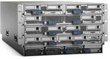
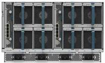
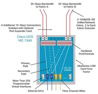
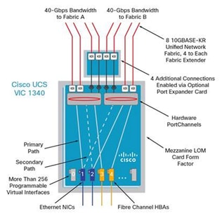
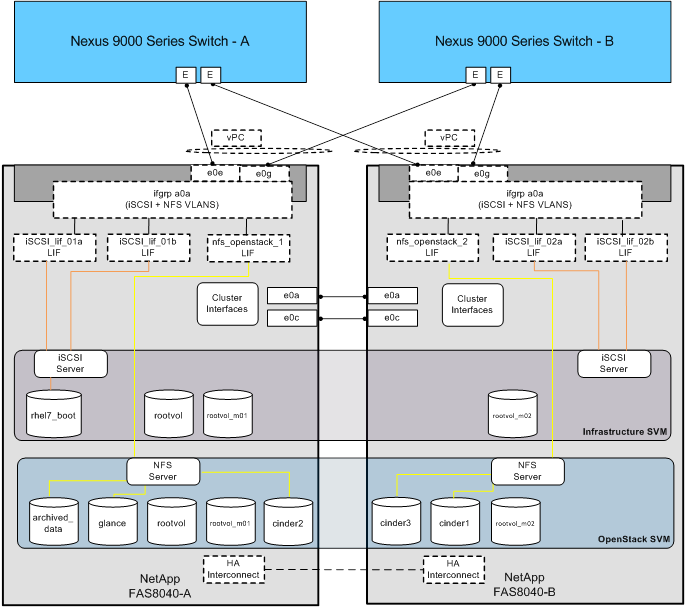
 Feedback