Cisco Data Intelligence Platform on Cisco UCS C240 M5 with Cloudera Data Platform Running Apache Ozone
Available Languages
Bias-Free Language
The documentation set for this product strives to use bias-free language. For the purposes of this documentation set, bias-free is defined as language that does not imply discrimination based on age, disability, gender, racial identity, ethnic identity, sexual orientation, socioeconomic status, and intersectionality. Exceptions may be present in the documentation due to language that is hardcoded in the user interfaces of the product software, language used based on RFP documentation, or language that is used by a referenced third-party product. Learn more about how Cisco is using Inclusive Language.
- US/Canada 800-553-2447
- Worldwide Support Phone Numbers
- All Tools
 Feedback
 Feedback

Cisco Data Intelligence Platform on Cisco UCS C240 M5 with Cloudera Data Platform Running Apache Ozone
Deployment Guide for Cisco Data Intelligence Platform on Cisco UCS C240 M5 with Cloudera Data Platform Private Cloud Base 7.1.5 Running Apache Ozone
Published: May 2021

In partnership with:
![]()
About the Cisco Validated Design Program
The Cisco Validated Design (CVD) program consists of systems and solutions designed, tested, and documented to facilitate faster, more reliable, and more predictable customer deployments. For more information, go to:
http://www.cisco.com/go/designzone.
ALL DESIGNS, SPECIFICATIONS, STATEMENTS, INFORMATION, AND RECOMMENDATIONS (COLLECTIVELY, "DESIGNS") IN THIS MANUAL ARE PRESENTED "AS IS," WITH ALL FAULTS. CISCO AND ITS SUPPLIERS DISCLAIM ALL WARRANTIES, INCLUDING, WITHOUT LIMITATION, THE WARRANTY OF MERCHANTABILITY, FITNESS FOR A PARTICULAR PURPOSE AND NONINFRINGEMENT OR ARISING FROM A COURSE OF DEALING, USAGE, OR TRADE PRACTICE. IN NO EVENT SHALL CISCO OR ITS SUPPLIERS BE LIABLE FOR ANY INDIRECT, SPECIAL, CONSEQUENTIAL, OR INCIDENTAL DAMAGES, INCLUDING, WITHOUT LIMITATION, LOST PROFITS OR LOSS OR DAMAGE TO DATA ARISING OUT OF THE USE OR INABILITY TO USE THE DESIGNS, EVEN IF CISCO OR ITS SUPPLIERS HAVE BEEN ADVISED OF THE POSSIBILITY OF SUCH DAMAGES.
THE DESIGNS ARE SUBJECT TO CHANGE WITHOUT NOTICE. USERS ARE SOLELY RESPONSIBLE FOR THEIR APPLICATION OF THE DESIGNS. THE DESIGNS DO NOT CONSTITUTE THE TECHNICAL OR OTHER PROFESSIONAL ADVICE OF CISCO, ITS SUPPLIERS OR PARTNERS. USERS SHOULD CONSULT THEIR OWN TECHNICAL ADVISORS BEFORE IMPLEMENTING THE DESIGNS. RESULTS MAY VARY DEPENDING ON FACTORS NOT TESTED BY CISCO.
CCDE, CCENT, Cisco Eos, Cisco Lumin, Cisco Nexus, Cisco StadiumVision, Cisco TelePresence, Cisco WebEx, the Cisco logo, DCE, and Welcome to the Human Network are trademarks; Changing the Way We Work, Live, Play, and Learn and Cisco Store are service marks; and Access Registrar, Aironet, AsyncOS, Bringing the Meeting To You, Catalyst, CCDA, CCDP, CCIE, CCIP, CCNA, CCNP, CCSP, CCVP, Cisco, the Cisco Certified Internetwork Expert logo, Cisco IOS, Cisco Press, Cisco Systems, Cisco Systems Capital, the Cisco Systems logo, Cisco Unified Computing System (Cisco UCS), Cisco UCS B-Series Blade Servers, Cisco UCS C-Series Rack Servers, Cisco UCS S-Series Storage Servers, Cisco UCS Manager, Cisco UCS Management Software, Cisco Unified Fabric, Cisco Application Centric Infrastructure, Cisco Nexus 9000 Series, Cisco Nexus 7000 Series. Cisco Prime Data Center Network Manager, Cisco NX-OS Software, Cisco MDS Series, Cisco Unity, Collaboration Without Limitation, EtherFast, EtherSwitch, Event Center, Fast Step, Follow Me Browsing, FormShare, GigaDrive, HomeLink, Internet Quotient, IOS, iPhone, iQuick Study, LightStream, Linksys, MediaTone, MeetingPlace, MeetingPlace Chime Sound, MGX, Networkers, Networking Academy, Network Registrar, PCNow, PIX, PowerPanels, ProConnect, ScriptShare, SenderBase, SMARTnet, Spectrum Expert, StackWise, The Fastest Way to Increase Your Internet Quotient, TransPath, WebEx, and the WebEx logo are registered trademarks of Cisco Systems, Inc. and/or its affiliates in the United States and certain other countries. (LDW_UP).
All other trademarks mentioned in this document or website are the property of their respective owners. The use of the word partner does not imply a partnership relationship between Cisco and any other company. (0809R)
© 2021 Cisco Systems, Inc. All rights reserved.
Deployment Hardware and Software
Cloudera Data Platform (CDP) Private Cloud is built for cloud-native speed, scale, and economics for the connected data lifecycle. CDP is faster than traditional on-premise data management solutions and cloud services, and responds faster to changing business requirements, providing a quicker adoption of innovation.
The CDP private cloud base is built on Hadoop 3.x distribution. Hadoop developed several capabilities since its inception. However, Hadoop 3.0 had been an eagerly awaited major release with many new features and optimizations. Upgrading from Hadoop 2.x to 3.0 is a paradigm shift since it enables diverse computing resources, such as CPU, GPU, and FPGA ,to work on data and leverage AI/ML methodologies. It supports flexible and elastic containerized workloads managed either by Hadoop scheduler such as YARN or Kubernetes, distributed deep learning, GPU enabled Spark workloads, and so on. Also, Hadoop 3.0 offers better reliability and availability of metadata through multiple standby name nodes, disk balancing for evenly utilized data nodes, enhanced workloads scheduling with YARN, and overall improved operational efficiency.
Apache Ozone 1.0 was released as a part of CDP Private Cloud Base 7.1.4 and it provides an optimized and shared storage compute infrastructure across the entire data lifecycle, increasing efficiency and lowering cost by reducing compute infrastructure requirements for analytics.
Apache Ozone provides the foundation for the next generation of storage architecture for Hadoop, where data blocks are organized in storage containers for higher scale and handling of small objects. This has been a major architectural enhancement in how storage was managed in Hadoop with HDFS to how Apache Ozone manages it, removing limitation of HDFS while supporting features such as:
● Apache Ozone is an object store for Hadoop supporting both HDFS API and S3 API allowing for several new use cases
● Supports 10s of billions of files
● Supports 400 TB / server with potential 1PB/server support in the future
● Supports 16TB hard disks (HDD/Flash) with potential to support larger drives in the future
● Continue to support data locality and separation of storage and compute like HDFS
In this reference architecture, Cisco Data Intelligence Platform (CDIP) is thoughtfully designed, supports data intensive workloads with Cloudera Data Platform Private cloud base, and Storage dense nodes with Apache Ozone.
This CVD is based on Cisco Data Intelligence Platform Private cloud base on Cisco UCS C240 M5 Rack Server with Cloudera Data Platform Private Cloud Base (CDP PvC) 7.1.5 with Apache Ozone as the distributed Filesystem for CDP on-premise. Cisco UCS C240 M5 Rack Servers deliver a highly dense, cost-optimized, on-premises storage with broad infrastructure flexibility for object storage, Hadoop, and Big Data analytics solutions.
This CVD offers customers the ability to consolidate their data lake further with larger storage per data node with Apache Ozone helping with the following savings:
● Infrastructure cost
● Software licensing cost
● Smaller datacenter footprint
● Support for HDFS and S3 and billions of objects supporting both large and small files in a similar fashion.
CDIP with Cloudera Data Platform enables the customer to independently scale storage and computing resources as needed while offering an exabyte scale architecture with low total cost of ownership (TCO) and future-proof architecture with the latest technology offered by Cloudera.
Furthermore, CDIP offers a single pane of glass management with Cisco Intersight.
Big Data and machine learning have progressed to the point where they are being implemented in production systems running 24x7. There exists a very clear need for a proven, dependable, high-performance platform for the ingestion, processing, storage, and analysis of data, as well as the seamless dissemination of the output, results, and insights of the analysis.
This solution implements Cloudera Data Platform Private Cloud Base (CDP PvC Base) with Apache Ozone on Cisco Data Intelligence Platform (CDIP) architecture, a world-class platform specifically designed for demanding workloads that is both easy to scale and easy to manage, even as the requirements grow to thousands of servers and petabytes of storage.
Many companies, recognizing the immense potential of big data and machine learning technology, are gearing up to leverage these new capabilities, building out departments and increasing hiring. However, these efforts have a new set of challenges:
● Making data available to the diverse set of users (data engineers, analysts, data scientists) who need it
● Management and processing of Exabyte scale storage
● Supporting Objects (S3) and different variety of data and file types
● Reduce data center footprint with better consolidation of storage
● Enabling access to high-performance computing resources, GPUs, that also scale with the data growth
● Allowing people to work with the data using the environments in which they are familiar
● Enabling the automated production of those results
● Managing the data for compliance and governance
● Scaling the system as the data grows
● Managing and administering the system in an efficient, cost-effective way
This solution is based on the Cisco Data Intelligence Platform that includes computing, storage, connectivity, capabilities built on Cisco Unified Computing System (Cisco UCS) infrastructure, using Cisco UCS C-Series and S-Series Rack Servers and unified management with Cisco Intersight to help companies manage the entire infrastructure from a single pane of glass along with Cloudera Data Platform to provide the software for fast ingest of data and managing and processing exabyte scale data being collected. This architecture is specifically designed for performance and linear scalability for big data and machine learning workload.
The intended audience of this document includes sales engineers, field consultants, professional services, IT managers, partner engineering and customers who want to deploy the Cloudera Data Platform Private Cloud base with Apache Ozone on the Cisco Data Intelligence Platform (Cisco UCS M5 Rack-Mount servers).
This document describes the architecture, design choices, and deployment procedures for Cisco Data Intelligence Platform using Cloudera Data Platform Private Cloud Base with Apache Ozone on Cisco UCS C240 M5.
This document also serves as a step-by-step guide on how to deploy Cloudera Data Platform on a 27-node cluster of Cisco UCS C240 M5 Rack Server.
This solution extends the portfolio of Cisco Data Intelligence Platform (CDIP) architecture with Cloudera Data Platform Private Cloud base with Apache Ozone, a state-of-the-art distributed storage which is the successor to Hadoop Filesystem (HDFS). Apache Ozone overcomes some of the storage limitations of HDFS while providing a richer support natively for Objects and S3 API support, higher consolidation of storage per node and a better lab footprint. Furthermore, as the enterprise’s requirements and needs change over time, the platform can grow to thousands of servers, at exabytes of storage, and tens of thousands of cores to process this data.
The following will be implemented in this validated design:
● Cisco Intersight to configure and manage Cisco Infrastructure
● Data lake provided by Cloudera Data Platform Private Cloud Base on Cisco UCS servers
● Next-generation data storage with Apache Ozone providing both HDFS and S3 API support storage for a data lake
● Intel Based 3.8TB SATA SSDs as storage drives for Apache Ozone
This CVD details the process of installing Cloudera Data Platform Private Cloud Base including the installation of Apache Ozone, the prerequisites for Cloudera Data Platform Private Cloud base, and the configuration details of the cluster.
Apache Ozone Brings the Best of HDFS and Object Store
● Overcomes HDFS limitations
◦ Can support billions of files (unlike HDFS which only supports up to 500 million files).
◦ Can currently support 400 TB/ node with potential of supporting 1PB /node at a later point in time unlike HDFS which only supports up to 100 TB/node.
◦ Supports 16TB drives unlike HDFS which only supports up to 8TB drives.
◦ Can scale to Exabyte scale.
● Overcome Object Store limitations
◦ Can support large files with linear performance. Like HDFS, Apache Ozone breaks files into smaller chunks (Object stores fail to do this and don’t perform linearly with large files), solving the large file problems often hit in object stores.
◦ Separates control and data plane enabling high performance. Supports very fast reads out of any of the three replicas.
● Apache Ozone fully migrates a HDFS cluster to Apache Ozone cluster.
● Supports data locality similar to HDFS and disaggregate architecture.
● Applications like Apache Spark, Hive and YARN, work without any modifications when using Ozone. Ozone comes with a Java client library, S3 protocol support, and a command line interface which makes it easy to use and administer.
Benefits of Apache Ozone to Customers
Apache Ozone brings storage consolidation in a data lake and provides customers with the following:
● Lower Infrastructure cost
● Better TCO and ROI on their investment
● Lower datacenter footprint
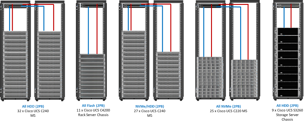
Figure 1. Data Lake Storage Consolidation with Apache Ozone
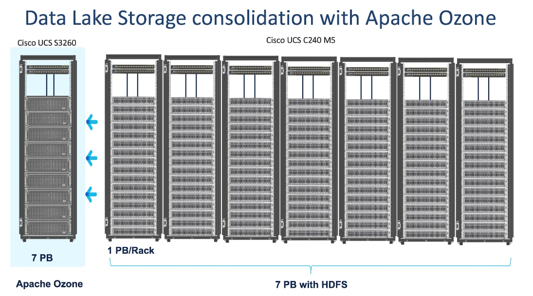
Figure 2. Data Lake Storage Consolidation with Apache ozone and Intel 3.8TB SATA SSD Drives
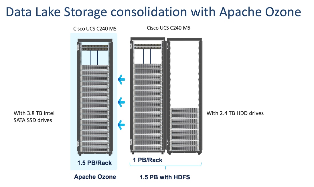
![]() The focus of this CVD will be the 3.8TB Intel SATA SSD 1x DWPD EV drives.
The focus of this CVD will be the 3.8TB Intel SATA SSD 1x DWPD EV drives.
Cisco Data Intelligence Platform
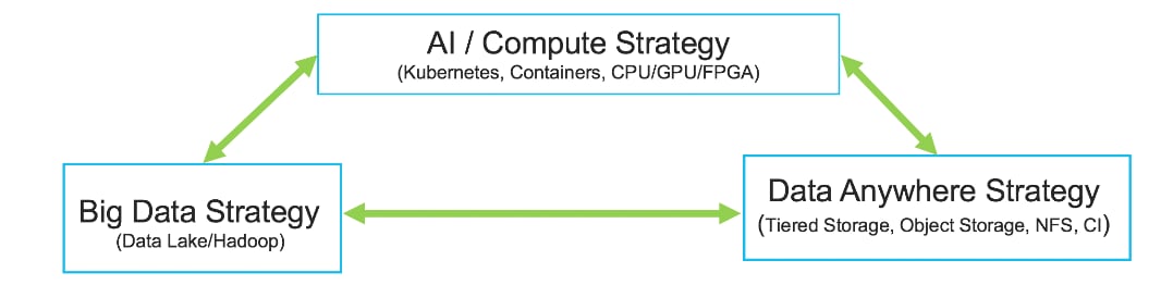
Cisco Data Intelligence Platform (CDIP) is a cloud-scale architecture which brings together big data, AI/compute farm, and storage tiers to work together as a single entity while also being able to scale independently to address the IT issues in the modern data center. This architecture provides the following:
● Extremely fast data ingest, and data engineering done at the data lake.
● AI compute farm allowing for different types of AI frameworks and compute types (GPU, CPU, FPGA) to work on this data for further analytics.
![]() GPU and FPGA are not supported in this release of Cloudera Private Cloud Experiences 1.0.2.
GPU and FPGA are not supported in this release of Cloudera Private Cloud Experiences 1.0.2.
● Seamlessly scale the architecture to thousands of nodes with a single pane of glass management using Cisco Intersight and Cisco Application Centric Infrastructure (ACI).
● Cisco Data Intelligence Platform caters to the evolving architecture bringing together a fully scalable infrastructure with centralized management and fully supported software stack (in partnership with industry leaders in the space) to each of these three independently scalable components of the architecture including data lake, AI/ML and Object stores.
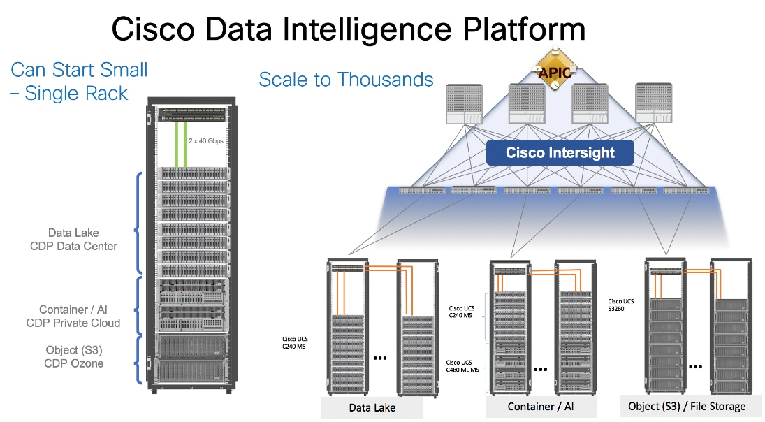
Figure 3. Cisco Data Intelligent Platform
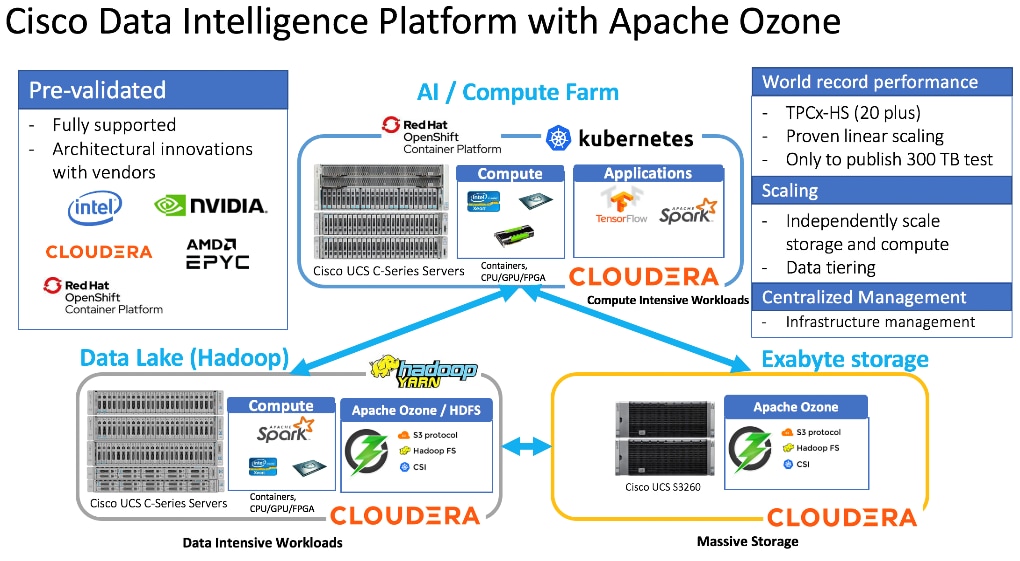
Cisco Data Intelligence Platform with Cloudera Data Platform
Cisco developed numerous industry leading Cisco Validated Designs (reference architectures) in the area of Big Data, compute farm with Kubernetes (CVD with RedHat OpenShift Container Platform) and Object store.
A CDIP architecture can be fully enabled by the Cloudera Data Platform with the following components:
● Data lake enabled through CDP PvC Base with Apache Ozone
● Private Cloud with compute on Kubernetes can be enabled through CDP Private Cloud Experiences
● Exabyte storage enabled through Apache Ozone
Figure 4. Cisco Data Intelligence Platform with Apache Ozone
This architecture can start from a single rack and scale to thousands of nodes with a single pane of glass management with Cisco Application Centric Infrastructure (ACI).
Figure 5. Cisco Data Intelligent Platform at Scale
Cisco Data Intelligence Platform reference architectures are carefully designed, optimized, and tested with the leading big data and analytics software distributions to achieve a balance of performance and capacity to address specific application requirements. You can deploy these configurations as is or use them as templates for building custom configurations. You can scale your solution as your workloads demand, including expansion to thousands of servers through the use of Cisco Nexus 9000 Series Switches. The configurations vary in disk capacity, bandwidth, price, and performance characteristics.
Data Lake Reference Architecture
Figure 6. Cisco UCS Integrated Infrastructure for Big Data and Analytics – Modernize Hadoop Infrastructure
Dense Storage Apache Ozone Reference Architecture
Table 1 lists the CDIP Apache Ozone reference architecture.
Table 1. Cisco Data Intelligence Platform Apache Ozone Reference Architecture for Data Lake
|
|
High Performance |
High Capacity |
Extreme Capacity |
| Server |
16 x Cisco UCS C240 M5 Rack Servers with small-form-factor (SFF) drives |
Cisco UCS S3260 with Single Node
|
Cisco UCS S3260 with Dual Node |
| CPU |
2 x 2nd Gen Intel® Xeon® Scalable Processors 5218R processors (2 x 20 cores, at 2.1 GHz) |
2 x 2nd Gen Intel Xeon Scalable Processor 6230R (2 x 26 cores, 2.1 GHz) |
2 x 2nd Gen Intel Xeon Scalable Processor 6230R (2 x 26 cores, 2.1 GHz) |
| Memory |
12 x 32GB DDR4 (384 GB) |
12 x 32GB 2666 MHz (384 GB) |
12 x 32GB 2666 MHz (192 GB) per Node |
| Boot |
2 x 960GB M.2 SATA Boot SSDs |
2 x 960GB SATA Boot SSDs |
2 x 960GB SATA Boot SSDs |
| Storage |
24 x 3.8TB Intel SATA SSD (1x DWPD Enterprise Value) + 2 x 3.2TB Intel P4610 NVMe |
48x8TB drives + 2 x 3.2TB Intel P4610 NVMe |
24x16TB drives + 2 x 3.2TB Intel P4610 NVMe |
| VIC |
25 Gigabit Ethernet (Cisco UCS VIC 1457) or 40/100 Gigabit Ethernet (Cisco UCS VIC 1497 recommended) |
25 Gigabit Ethernet (Cisco UCS VIC 1455) or 40/100 Gigabit Ethernet (Cisco UCS VIC 1495) |
25 Gigabit Ethernet (Cisco UCS VIC 1455) or 40/100 Gigabit Ethernet (Cisco UCS VIC 1495) |
| Storage controller |
Cisco 12-Gbps modular SAS host bus adapter (HBA) |
Cisco UCS S3260 dual RAID controller |
Cisco UCS S3260 dual RAID controller |
| Network connectivity |
Cisco UCS 6332 Fabric Interconnect or Cisco UCS 6454/64108 Fabric Interconnect |
Cisco UCS 6332 Fabric Interconnect or Cisco UCS 6454/64108 Fabric Interconnect |
Cisco UCS 6332 Fabric Interconnect or Cisco UCS 6454/64108 Fabric Interconnect |
Table 2 lists the data lake, private cloud, and dense storage with HDFS reference architecture for Cisco Data Intelligence Platform.
Table 2. Cisco Data Intelligence Platform Data Lake Configuration with HDFS
|
|
High Performance |
Performance |
Capacity |
High Capacity |
| Servers |
16 x Cisco UCS C220 M5SN Rack Servers with small-form-factor (SFF) drives (UCSC-C220-M5SN) |
16 x Cisco UCS C240 M5 Rack Servers with small-form-factor (SFF) drives |
16 x Cisco UCS C240 M5 Rack Servers with large-form-factor (LFF) drives |
8 x Cisco UCS S3260 Storage Servers each with dual nodes |
| CPU |
2 x 2nd Gen Intel® Xeon® Scalable Processors 6230R (2 x 26 cores, at 2.1 GHz) |
2 x 2nd Gen Intel® Xeon® Scalable Processors 5218R processors (2 x 20 cores, at 2.1 GHz) |
2 x 2nd Gen Intel Xeon Scalable Processors 5218R (2 x 20 cores, at 2.1 GHz) |
2 x 2nd Gen Intel Xeon Scalable Processors 6230R (2 x 26 cores, 2.1 GHz) |
| Memory |
12 x 32GB DDR4 (384 GB) |
12 x 32GB DDR4 (384 GB) |
12 x 32GB DDR4 (384 GB) |
12 x 32GB DDR4 (384 GB) |
| Boot |
2 x 240GB M.2 SATA Boot SSDs |
2 x 240GB M.2 SATA Boot SSDs |
2 x 240GB M.2 SATA Boot SSDs |
2 x 480GB SATA SSDs |
| Storage |
10 x 8TB 2.5in U.2 Intel P4510 NVMe High Perf. Value Endurance |
26 x 2.4TB 10K rpm SFF SAS HDDs or 26 x 3.8TB Intel SATA SSD (1x DWPD Enterprise Value) |
12 x 8-TB 7.2K rpm LFF SAS HDDs |
28 x 4TB 7.2K rpm LFF SAS HDDs per server node |
| Virtual interface card (VIC) |
25 Gigabit Ethernet (Cisco UCS VIC 1457) or 40/100 Gigabit Ethernet (Cisco UCS VIC 1497) |
25 Gigabit Ethernet (Cisco UCS VIC 1457) or 40/100 Gigabit Ethernet (Cisco UCS VIC 1497) |
25 Gigabit Ethernet (Cisco UCS VIC 1457) or 40/100 Gigabit Ethernet (Cisco UCS VIC 1497) |
40 Gigabit Ethernet (Cisco UCS VIC 1387) or 25 Gigabit Ethernet (Cisco UCS VIC 1455) or 40/100 Gigabit Ethernet (Cisco UCS VIC 1495) |
| Storage controller |
NVMe Switch included in the optimized server |
Cisco 12-Gbps SAS modular RAID controller with 4-GB flash-based write cache (FBWC) or Cisco 12-Gbps modular SAS host bus adapter (HBA) |
Cisco 12-Gbps SAS modular RAID controller with 2-GB FBWC or Cisco 12-Gbps modular SAS host bus adapter (HBA) |
Cisco 12-Gbps SAS Modular RAID Controller with 4-GB flash-based write cache (FBWC) |
| Network connectivity |
Cisco UCS 6332 Fabric Interconnect or Cisco UCS 6454/64108 Fabric Interconnect |
Cisco UCS 6332 Fabric Interconnect or Cisco UCS 6454/64108 Fabric Interconnect |
Cisco UCS 6332 Fabric Interconnect or Cisco UCS 6454/64108 Fabric Interconnect |
Cisco UCS 6332 Fabric Interconnect or Cisco UCS 6454/64108 Fabric Interconnect |
| GPU (optional) |
Up to 2 x NVIDIA Tesla T4 with 16 GB memory each |
Up to 2 x NVIDIA Tesla V100 with 32 GB memory each Or Up to 6 x NVIDIA Tesla T4 with 16 GB memory each |
2 x NVIDIA Tesla V100 with 32 GB memory each Or Up to 6 x NVIDIA Tesla T4 with 16 GB memory each |
|
Private Cloud Reference Architecture
Table 3 lists the CDIP private cloud configuration for master and worker nodes.
Table 3. Cisco Data Intelligence Platform Private Cloud configuration (Master and worker nodes)
|
|
High Core Option |
| Servers |
8 x Cisco UCS C240 M5 Rack Servers |
| CPU |
2 x 2nd Gen Intel Xeon Scalable Processor 6230R (2 x 26 cores, 2.1 GHz) |
| Memory |
12 x 32GB DDR4 (384 GB) |
| Boot |
M.2 with 2 x 960GB SSDs |
| Storage |
4 x 2.4TB 10K rpm SFF SAS HDDs or 4 x 1.6TB Enterprise Value SATA SSDs or 4x 3.8TB Intel SATA SSD (1x DWPD Enterprise Value) |
| VIC |
25 Gigabit Ethernet (Cisco UCS VIC 1457) or 40/100 Gigabit Ethernet (Cisco UCS VIC 1497) |
| Storage controller |
Cisco 12-Gbps SAS modular RAID controller with 4-GB FBWC or Cisco 12-Gbps modular SAS HBA |
| Network connectivity |
Cisco UCS 6332 Fabric Interconnect or Cisco UCS 6454/64108 Fabric Interconnect |
| GPU (optional) |
2 x NVIDIA TESLA V100 with 32-GB memory each or up to 6 x NVIDIA T4
|
As illustrated in Figure 4, this CVD was designed with the following:
● 27 x Cisco UCS C240 M5 running Cloudera Data Platform Private Cloud Base with Apache Ozone
Refer to http://www.cisco.com/go/bigdata_design to build a fully supported CDP Private Cloud Base on CDIP reference architecture with HDFS. This CVD does not provide the details to build a CDP Private Cloud Base with HDFS but only with Apache Ozone. For detailed instruction to deploy CDP Private Cloud Base with HDFS, click the following links:
Cisco Data Intelligence Platform with All NVMe Storage, Cisco Intersight, and Cloudera Data Platform
Cisco Data Intelligence Platform on Cisco UCS S3260 with Cloudera Data Platform
Cisco Data Intelligence Platform with Cloudera Data Platform
To deploy CDP Private Cloud Experiences on Red Hat OpenShift Container Platform, see: Cisco Data Intelligence Platform with Cloudera Data Platform Private Cloud Experiences
16 node cluster with Rack#1 hosting 16 Cisco UCS C240 M5 and 11 node Cisco UCS C240 M5 in Rack#2. Each link in Figure 7 represents a 40 Gigabit Ethernet link from each of the 16-server connected to a pair of Cisco Fabric Interconnect switches.
Figure 7. Cisco Data Intelligence Platform with Cloudera Data Platform Private Cloud Base running Apache Ozone
![]() The Cisco UCS VIC 1457 provides 10/25Gbps, and the Cisco UCS VIC 1497 provides 40/100Gbps connectivity for the Cisco UCS C-series rack server. For more information see: Cisco UCS C-Series Servers Managing Network Adapters.
The Cisco UCS VIC 1457 provides 10/25Gbps, and the Cisco UCS VIC 1497 provides 40/100Gbps connectivity for the Cisco UCS C-series rack server. For more information see: Cisco UCS C-Series Servers Managing Network Adapters.
![]() In this solution we configured quad-port mLOM VIC 1457 installed in Cisco UCS C240 M5 server with link 1-2 connected to Fabric A and link 3-4 connected to Fabric B to achieve 50GbE per server.
In this solution we configured quad-port mLOM VIC 1457 installed in Cisco UCS C240 M5 server with link 1-2 connected to Fabric A and link 3-4 connected to Fabric B to achieve 50GbE per server.
NVMe for Apache Ozone metadata is configured in RAID1 to provide business continuity if there is a hardware failure. This is not needed on pure compute nodes which only use them for caching. Master Nodes and Data Nodes uses NVMe to store Ozone metadata. The Compute Nodes use NVMe for shuffle and can be in JBOD. The mixed Compute Data Nodes use NVMe for both Apache Ozone metadata and shuffle which requires mount Ozone partitions across both drives as RAID1 (800GB), with the remaining space used for shuffle/cache as independent JBOD partitions. Scaling the Solution
Figure 5 illustrates how to scale the solution. Each pair of Cisco UCS 6332 Fabric Interconnects has 24 Cisco UCS C240 M5 servers connected to it. This allows for eight uplinks from each Fabric Interconnect to the Cisco Nexus 9332 switch. Six pairs of 6332 FIs can connect to a single switch with four uplink ports each. With 24 servers per FI, a total of 144 servers can be supported. Additionally, this solution can scale to thousands of nodes with the Cisco Nexus 9500 series family of switches.
In this reference architectures, each of the components is scaled separately, and for the purposes of this example, scaling is uniform. Two scale scenarios are as follows:
● Scaled architecture with 3:1 oversubscription with Cisco fabric interconnects and Cisco ACI
● Scaled architecture with 2:1 oversubscription with Cisco ACI
In the following scenarios, the goal is to populate up to a maximum of 200 leaf nodes in a Cisco ACI domain. Not all cases reach that number because they use the Cisco Nexus 9508 Switch for this sizing and not the Cisco Nexus 9516 Switch.
Scaled Architecture with 3:1 Oversubscription with Cisco Fabric Interconnects and Cisco ACI
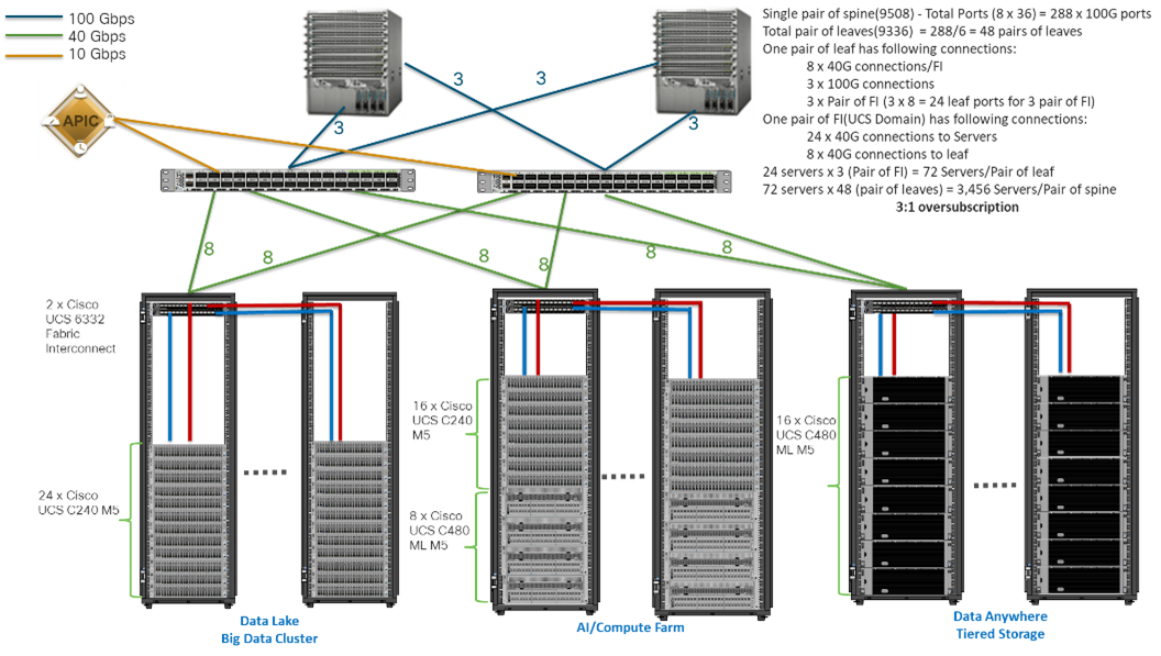
The architecture discussed here and shown in Figure 8 supports 3:1 network oversubscription from every node to every other node across a multidomain cluster (nodes in a single domain within a pair of Cisco fabric interconnects are locally switched and not oversubscribed).
From the viewpoint of the data lake, 24 Cisco UCS C240 M5 Rack Servers are connected to a pair of Cisco UCS 6332 Fabric Interconnects (with 24 x 40-Gbps throughput). From each fabric interconnect, 8 x 40-Gbps links connect to a pair of Cisco Nexus 9336 Switches. Three pairs of fabric interconnects can connect to a single pair of Cisco Nexus 9336 Switches (8 x 40-Gbps links per Fabric Interconnect to a pair of Cisco Nexus switches). Each of these Cisco Nexus 9336 Switches connects to a pair of Cisco Nexus 9508 Cisco ACI switches with 6 x 100-Gbps uplinks (connecting to a Cisco N9K-X9736C-FX line card). the Cisco Nexus 9508 Switch with the Cisco N9K-X9736C-FX line card can support up to 36 x 100-Gbps ports, each and 8 such line cards.
Figure 8. Scaled Architecture with 3:1 Oversubscription with Cisco Fabric Interconnects and Cisco ACI
Scaled Architecture with 2:1 Oversubscription with Cisco ACI
In this scenario as shown in Figure 9, the Cisco Nexus 9508 Switch with the Cisco N9K-X9736C-FX line card can support up to 36 x 100-Gbps ports, each and 8 such line cards.
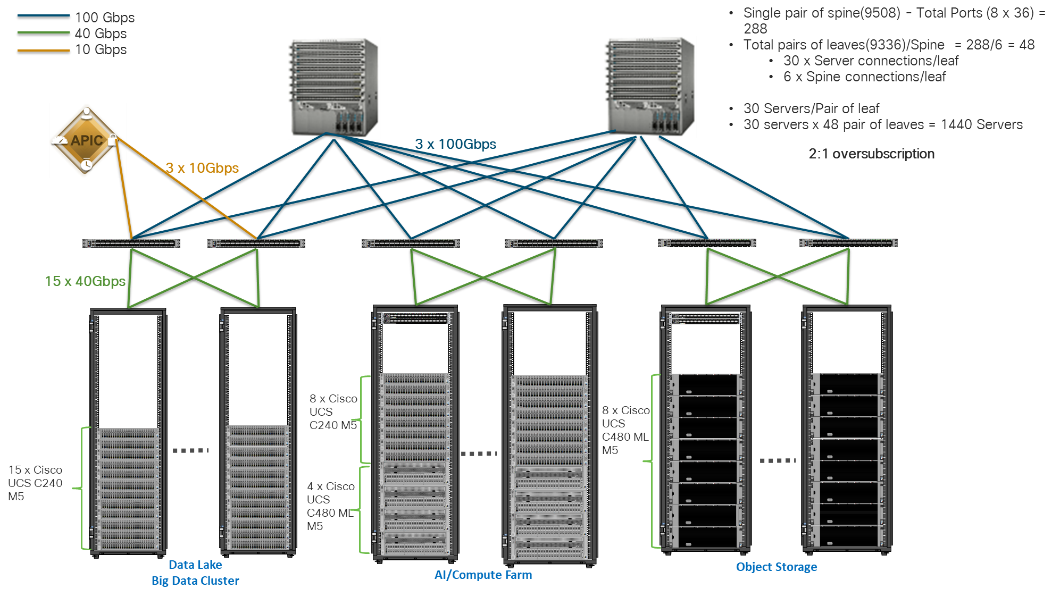
For the 2:1 oversubscription, 30 Cisco UCS C240 M5 Rack Servers are connected to a pair of Cisco Nexus 9336 Switches, and each Cisco Nexus 9336 connects to a pair of Cisco Nexus 9508 Switches with three uplinks each. A pair of Cisco Nexus 9336 Switches can support 30 servers and connect to a spine with 6 x 100-Gbps links on each spine. This single pod (pair of Cisco Nexus 9336 Switches connecting to 30 Cisco UCS C240 M5 servers and 6 uplinks to each spine) can be repeated 48 times (288/6) for a given Cisco Nexus 9508 Switch and can support up to1440 servers.
To reduce the oversubscription ratio (to get 1:1 network subscription from any node to any node), you can use just 15 servers under a pair of Cisco Nexus 9336 Switches and then move to Cisco Nexus 9516 Switches (the number of leaf nodes would double).
To scale beyond this number, multiple spines can be aggregated.
Figure 9. Scaled Architecture with 2:1 Oversubscription with Cisco ACI
![]() In a 5-rack system, 80 percent of traffic is expected to go upstream.
In a 5-rack system, 80 percent of traffic is expected to go upstream.
Cisco Data Intelligence Platform
This section describes the components used to build Cisco Data Intelligence Platform, a highly scalable architecture designed to meet a variety of scale-out application demands with seamless data integration and management integration capabilities.
Cisco Data Intelligence Platform powered by Cloudera Data Platform delivers:
● Latest generation of CPUs from Intel (2nd generation Intel Scalable family, with Cascade Lake CLXR).
● Cloud scale and fully modular architecture where big data, AI/compute farm, and massive storage tiers work together as a single entity and each CDIP component can also scale independently to address the IT issues in the modern data center.
● World record Hadoop performance both for MapReduce and Spark frameworks published at TPCx-HS benchmark.
● AI compute farm offers different types of AI frameworks and compute types (GPU, CPU, FPGA) to work data for analytics.
● A massive storage tier enables to gradually retire data and quick retrieval when needed on a storage dense sub-systems with a lower $/TB providing a better TCO.
● Data compression with FPGA, offload compute-heavy compression tasks to FPGA, relieve CPU to perform other tasks, and gain significant performance.
● Seamlessly scale the architecture to thousands of nodes.
● Single pane of glass management with Cisco Intersight.
● ISV Partner ecosystem – Top notch ISV partner ecosystem, offering best of the breed end-to-end validated architectures.
● Pre-validated and fully supported platform.
● Disaggregate Architecture – Supporting separation of storage and compute for a data lake.
● Container Cloud – Kubernetes – Compute farm backed by the industry leading container orchestration engine and offers the very first container cloud plugged with data lake and object store.
Cloudera Data Platform – Private Cloud Base (PvC)
With the merger of Cloudera and Hortonworks, a new Cloudera software named Cloudera Data Platform (CDP) combined the best of Hortonwork’s and Cloudera’s technologies to deliver the industry leading first enterprise data cloud. CDP Private Cloud Base is the on-prem version of CDP and CDP Private Cloud Experiences is the on-prem version of Private Cloud to enable compute on Kubernetes with Red Hat OpenShift Container Platform. This unified distribution is a scalable and customizable platform where workloads can be securely provisioned. CDP gives a clear path for extending or refreshing your existing HDP and CDH deployments and set the stage for cloud-native architecture.
CDP Private Cloud Base can be deployed either with Hadoop Filesystem (HDFS) or Apache Ozone or both as the underlying distributed storage. However, this CVD primarily focuses on Apache Ozone as the underlying distributed filesystem for Hadoop.
Apache Ozone is a scalable, redundant, and distributed object store for Hadoop. Apart from scaling to billions of objects of varying sizes, Ozone can function effectively in containerized environments such as Kubernetes and YARN. Applications using frameworks like Apache Spark, YARN and Hive work natively without any modifications. Apache Ozone is built on a highly available, replicated block storage layer called Hadoop Distributed Data Store (HDDS).
Ozone consists of volumes, buckets, and keys:
● Volumes are similar to user accounts. Only administrators can create or delete volumes.
● Buckets are similar to directories. A bucket can contain any number of keys, but buckets cannot contain other buckets.
● Keys are similar to files. Each key is part of a bucket, which, in turn, belongs to a volume. Ozone stores data as keys inside these buckets.
● A hierarchical directory tree can be created inside a bucket using directory separators in
Apache Ozone is a distributed key-value store that can manage both small and large files alike. While HDFS provides POSIX-like semantics, Ozone looks and behaves like an Object Store.
When a key is written to Apache Ozone, the associated data is stored on the DataNodes in chunks called blocks. Therefore, each key is associated with one or more blocks. Within the DataNodes, a series of unrelated blocks is stored in a container, allowing many blocks to be managed as a single entity.
Apache Ozone separates management of namespaces and storage, helping it to scale effectively. Ozone Manager manages the namespaces while Storage Container Manager handles the containers.
Figure 10. Basic Architecture for Ozone
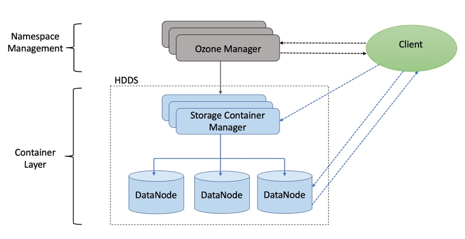
Apache Ozone is a scale-out architecture with minimal operational overheads and long-term maintenance efforts. Ozone can be co-located with HDFS with single security and governance policies for easy data exchange or migration and also offers seamless application portability. Ozone enables separation of compute and storage via the S3 API as well as similar to HDFS, it also supports data locality for applications that choose to use it.
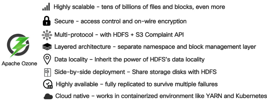
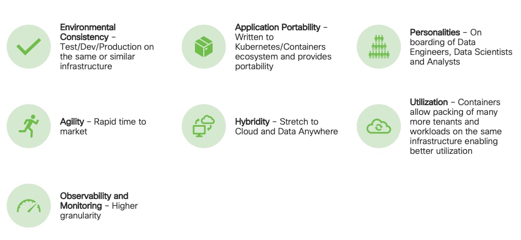
The design of Ozone was guided by the key principles listed in Figure 11.
Figure 11. Ozone Design Principle
Cisco Unified Computing System
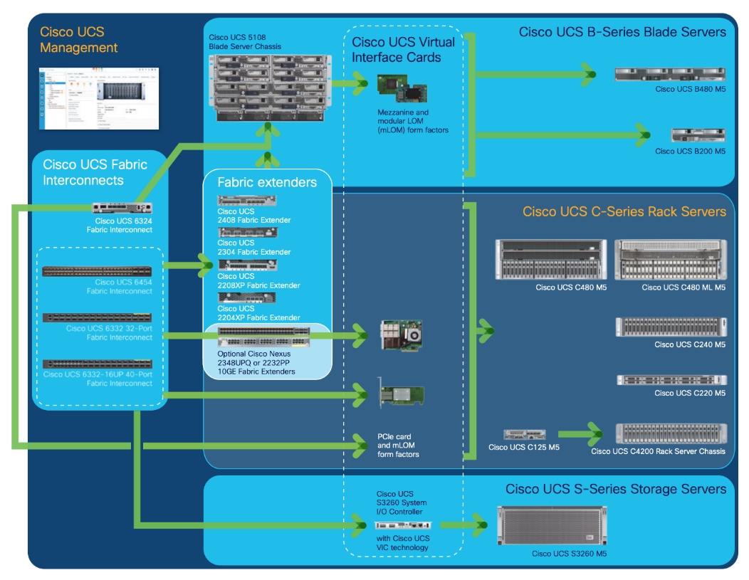
Cisco Unified Computing System (Cisco UCS) is a next-generation data center platform that unites computing, networking, storage access, and virtualization resources into a cohesive system designed to reduce Total Cost of Ownership (TCO) and increase business agility. The system integrates a low-latency, lossless 10/25/40/100 Gigabit Ethernet unified network fabric with enterprise-class, x86-architecture servers. The system is an integrated, scalable, multi-chassis platform in which all resources participate in a unified management domain (Figure 12).
Figure 12. Cisco UCS Component Hierarchy
Cisco UCS Manager (UCSM) resides within the Cisco UCS Fabric Interconnect. It makes the system self-aware and self-integrating, managing all the system components as a single logical entity. Cisco UCS Manager can be accessed through an intuitive GUI, a CLI, or an XML API. Cisco UCS Manager uses service profiles to define the personality, configuration, and connectivity of all resources within Cisco UCS, radically simplifying provisioning of resources so that the process takes minutes instead of days. This simplification allows IT departments to shift their focus from constant maintenance to strategic business initiatives.
Key Features
The following are some of the key feature of Cisco UCS Manager:
● Supports Cisco UCS B-Series Blade and Cisco UCS C-Series Rack Servers, the Cisco UCS C3260 storage server, Cisco UCS Mini, and the Cisco HyperFlex hyperconverged infrastructure.
● Programmatically controls server, network, and storage resources, with a unified, policy-driven management, so they can be efficiently managed at scale through software.
● Works with HTML 5, Java, or CLI graphical user interfaces.
● Can automatically detect, inventory, manage, and provision system components that are added or changed.
● Facilitates integration with third-party systems management tools.
● Builds on existing skills and supports collaboration across disciplines through role-based administration.
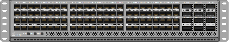
Cisco UCS 6300 Series Fabric Interconnects
Cisco UCS 6300 Series Fabric Interconnects provide high-bandwidth, low-latency connectivity for servers, with integrated, unified management provided for all connected devices by Cisco UCS Manager. Deployed in redundant pairs, Cisco fabric interconnects offer the full active-active redundancy, performance, and exceptional scalability needed to support the large number of nodes that are typical in clusters serving big data applications. Cisco UCS Manager enables rapid and consistent server configuration using service profiles, automating ongoing system maintenance activities such as firmware updates across the entire cluster as a single operation. Cisco UCS Manager also offers advanced monitoring with options to raise alarms and send notifications about the health of the entire cluster.
The Cisco UCS 6300 Series Fabric Interconnect is a One-Rack-Unit (1RU) providing low-latency, lossless 10 and 40 Gigabit Ethernet, Fiber Channel over Ethernet (FCoE), and Fiber Channel functions with management capabilities for the entire system. All servers attached to Fabric interconnects become part of a single, highly available management domain.
Figure 13. Cisco UCS 6332UP 32 -Port Fabric Interconnect

For more information, go to: https://www.cisco.com/c/en/us/products/collateral/servers-unified-computing/ucs-6300-series-fabric-interconnects/datasheet-c78-736682.html?cachemode=refresh
Cisco UCS 6400 Series Fabric Interconnect
The Cisco UCS 6400 Series Fabric Interconnects are a core part of the Cisco Unified Computing System, providing both network connectivity and management capabilities for the system. The Cisco UCS 6400 Series offer line-rate, low-latency, lossless 10/25/40/100 Gigabit Ethernet, Fibre Channel over Ethernet (FCoE), and Fibre Channel functions. (Figure 14 and Figure 15).
The Cisco UCS 6454 54-Port Fabric Interconnect (Figure 14) is a One-Rack-Unit (1RU) 10/25/40/100 Gigabit Ethernet, FCoE, and Fibre Channel switch offering up to 3.82 Tbps throughput and up to 54 ports. The switch has 28 10/25-Gbps Ethernet ports, 4 1/10/25- Gbps Ethernet ports, 6 40/100-Gbps Ethernet uplink ports, and 16 unified ports that can support 10/25-Gbps Ethernet ports or 8/16/32-Gbps Fibre Channel ports. All Ethernet ports are capable of supporting FCoE.
Figure 14. Cisco UCS 6454 Fabric Interconnect

The Cisco UCS 64108 Fabric Interconnect (Figure 15) is a 2-RU top-of-rack switch that mounts in a standard 19-inch rack such as the Cisco R Series rack. The 64108 is a 10/25/40/100 Gigabit Ethernet, FCoE and Fiber Channel switch offering up to 7.42 Tbps throughput and up to 108 ports. The switch has 16 unified ports (port numbers 1-16) that can support 10/25-Gbps SFP28 Ethernet ports or 8/16/32-Gbps Fibre Channel ports, 72 10/25-Gbps Ethernet SFP28 ports (port numbers 17-88), 8 1/10/25-Gbps Ethernet SFP28 ports (port numbers 89-96), and 12 40/100-Gbps Ethernet QSFP28 uplink ports (port numbers 97-108). All Ethernet ports are capable of supporting FCoE.
Figure 15. Cisco UCS 64108 Fabric Interconnect
Cisco UCS C-Series Rack-Mount Servers
It is designed to operate both in standalone environments and as part of Cisco UCS managed configuration, these servers enable organizations to deploy systems incrementally—using as many or as few servers as needed—on a schedule that best meets the organization’s timing and budget. Cisco UCS C-Series servers offer investment protection through the capability to deploy them either as standalone servers or as part of Cisco UCS. One compelling reason that many organizations prefer rack-mount servers is the wide range of I/O options available in the form of PCIe adapters. Cisco UCS C-Series servers support a broad range of I/O options, including interfaces supported by Cisco and adapters from third parties.
Cisco UCS 240M5 Storage Servers
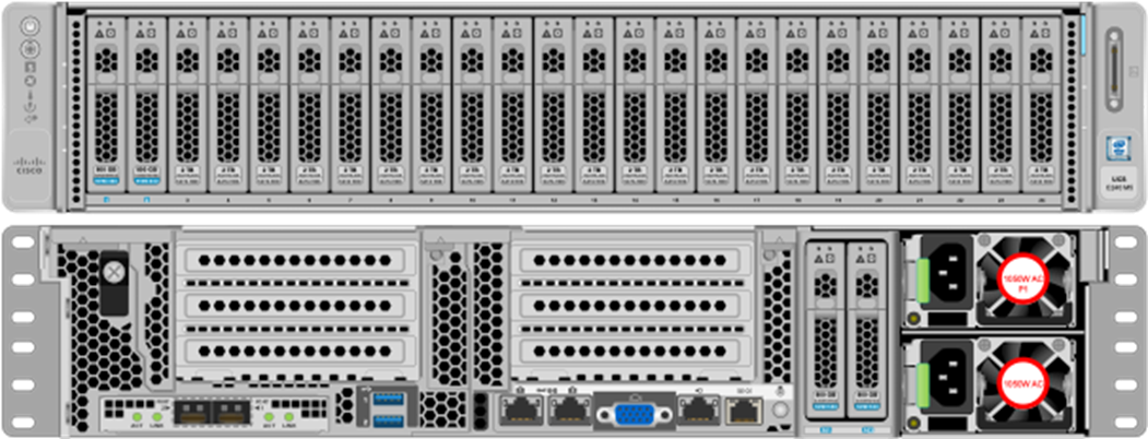
The Cisco UCS C240 M5 Rack-Mount Server (Figure 16) is a 2-socket, 2-Rack-Unit (2RU) rack server offering industry-leading performance and expandability. It supports a wide range of storage and I/O-intensive infrastructure workloads, from big data and analytics to collaboration. Cisco UCS C-Series Rack Servers can be deployed as standalone servers or as part of a Cisco Unified Computing System managed environment to take advantage of Cisco’s standards-based unified computing innovations that help reduce customers’ Total Cost of Ownership (TCO) and increase their business agility.
The latest update includes support for 2nd Generation Intel Xeon Scalable Processors, 2933-MHz DDR4 memory, and the new 512GB Intel OptaneTM DC Persistent Memory Modules (DCPMMs). With this combination of features, up to 9 TB of memory is possible (using 12 x 256 GB DDR4 DIMMs and 12 x 512 GB DCPMMs).
![]() Optane DCPMMs are not used in this architecture or CVD with Apache Ozone but highlights the capabilities of Cisco UCS C240 M5.
Optane DCPMMs are not used in this architecture or CVD with Apache Ozone but highlights the capabilities of Cisco UCS C240 M5.
The Cisco UCS C240 M5 Rack-Mount Server has the following features:
● Latest 2nd Generation Intel Xeon Scalable CPUs with up to 28 cores per socket
● Up to 24 DDR4 DIMMs for improved performance
● Up to 26 Small-Form-Factor (SFF) 2.5-inch drives, (up to 10 NVMe PCIe SSDs on the NVMe-optimized chassis version), or 12 Large-Form- Factor (LFF) 3.5-inch drives
● Support for 12-Gbps SAS modular RAID controller in a dedicated slot, leaving the remaining PCIe Generation 3.0 slots available for other expansion cards
● Modular LAN-On-Motherboard (mLOM) slot that can be used to install a Cisco UCS Virtual Interface Card (VIC) without consuming a PCIe slot, supporting dual 10/25/40-Gbps network connectivity
● Dual embedded Intel x550 10GBASE-T LAN-On-Motherboard (LOM) ports
● Modular M.2 or Secure Digital (SD) cards that can be used for boot
Figure 16. Cisco UCS C240M5 Rack-Mount Server
Cisco UCS Virtual Interface Cards (VICs)
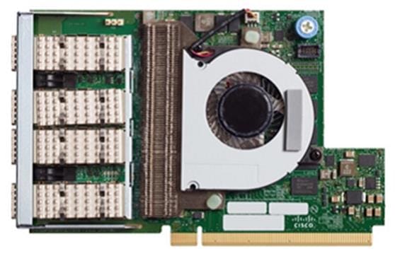
Cisco UCS VIC 1457
The Cisco UCS VIC 1457 (Figure 17) is a quad-port Small Form-Factor Pluggable (SFP28) mLOM card designed for the M5 generation of Cisco UCS C-Series Rack Servers. The card supports 10/25-Gbps Ethernet or FCoE. The card can present PCIe standards-compliant interfaces to the host, and these can be dynamically configured as either NICs or HBAs.
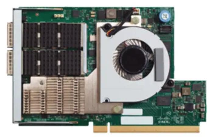
Cisco UCS VIC 1497
The Cisco VIC 1497 (Figure 18) is a dual-port Small Form-Factor (QSFP28) mLOM card designed for the M5 generation of Cisco UCS C-Series Rack Servers. The card supports 40/100-Gbps Ethernet and FCoE. The card can present PCIe standards-compliant interfaces to the host, and these can be dynamically configured as NICs and HBAs.
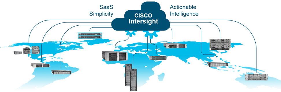
Cisco Intersight is Cisco’s systems management platform that delivers intuitive computing through cloud-powered intelligence. This platform offers a more intelligent level of management that enables IT organizations to analyze, simplify, and automate their environments in ways that were not possible with prior generations of tools. This capability empowers organizations to achieve significant savings in Total Cost of Ownership (TCO) and to deliver applications faster, so they can support new business initiatives.
Cisco Intersight is a Software as a Service (SaaS) infrastructure management which provides a single pane of glass management of CDIP infrastructure in the data center. Cisco Intersight scales easily, and frequent updates are implemented without impact to operations. Cisco Intersight Essentials enables customers to centralize configuration management through a unified policy engine, determine compliance with the Cisco UCS Hardware Compatibility List (HCL), and initiate firmware updates. Enhanced capabilities and tight integration with Cisco TAC enables more efficient support. Cisco Intersight automates uploading files to speed troubleshooting. The Intersight recommendation engine provides actionable intelligence for IT operations management. The insights are driven by expert systems and best practices from Cisco.
Cisco Intersight offers flexible deployment either as Software as a Service (SaaS) on Intersight.com or running on your premises with the Cisco Intersight virtual appliance. The virtual appliance provides users with the benefits of Cisco Intersight while allowing more flexibility for those with additional data locality and security requirements.
Cisco Intersight provides the following features for ease of operations and administration for the IT staff:
● Connected TAC
● Security Advisories
● Hardware Compatibility List (HCL)
To learn more about all the features of Intersight go to: https://www.cisco.com/c/en/us/products/servers-unified-computing/intersight/index.html
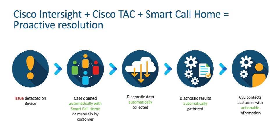
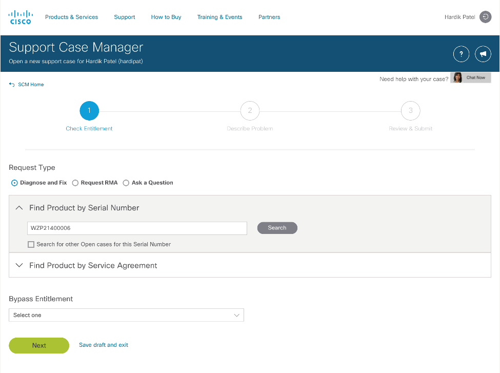
Connected TAC is an automated transmission of technical support files to the Cisco Technical Assistance Center (TAC) for accelerated troubleshooting.
Cisco Intersight enables Cisco TAC to automatically generate and upload Tech Support Diagnostic files when a Service Request is opened. If you have devices that are connected to Intersight but not claimed, Cisco TAC can only check the connection status and will not be permitted to generate Tech Support files. When enabled, this feature works in conjunction with the Smart Call Home service and with an appropriate service contract. Devices that are configured with Smart Call Home and claimed in Intersight can use Smart Call Home to open a Service Request and have Intersight collect Tech Support diagnostic files.
Figure 20. Cisco Intersight: Connected TAC
To enable Connected TAC, follow these steps:
1. Log into Intersight.com.
2. Click the Servers tab. Go to Server > Actions tab. From the drop-down list, click Open TAC Case.
3. Clicking Open TAC Case launches the Cisco URL for Support case manager where associated service contracts for Server or Fabric Interconnect is displayed.
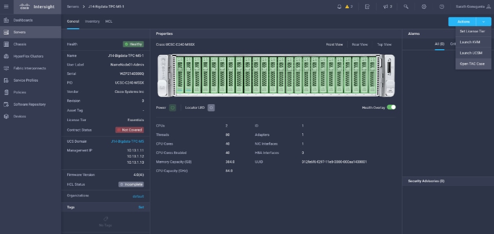
4. Click Continue.
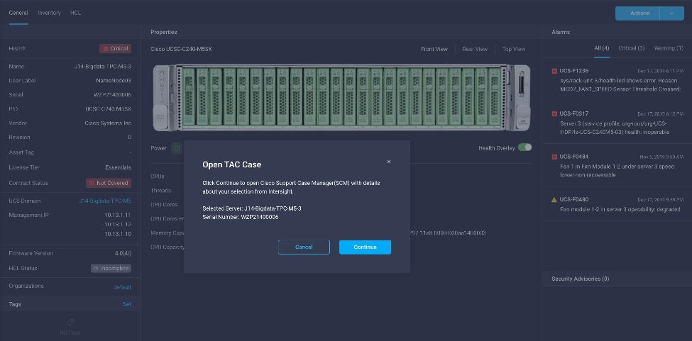
5. Follow the procedure to Open TAC Case.
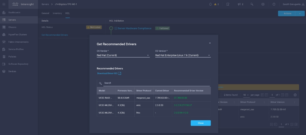
Cisco Intersight Integration for HCL
Cisco Intersight evaluates the compatibility of your Cisco UCS and Cisco HyperFlex systems to check if the hardware and software have been tested and validated by Cisco or Cisco partners. Cisco Intersight reports validation issues after checking the compatibility of the server model, processor, firmware, adapters, operating system, and drivers, and displays the compliance status with the Hardware Compatibility List (HCL).
You can use Cisco UCS Tools, a host utility vSphere Installation Bundle (VIB), or OS Discovery Tool, an open source script to collect OS and driver information to evaluate HCL compliance.
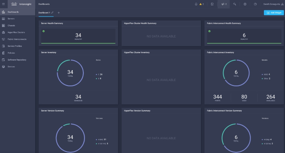
In Cisco Intersight, you can view the HCL compliance status in the dashboard (as a widget), the Servers table view, and the Server details page.
![]() For more information, go to: https://www.intersight.com/help/features#compliance_with_hardware_compatibility_list_(hcl)
For more information, go to: https://www.intersight.com/help/features#compliance_with_hardware_compatibility_list_(hcl)
Figure 21. Example of HCL Status and Driver Recommendation for RHEL 7.6
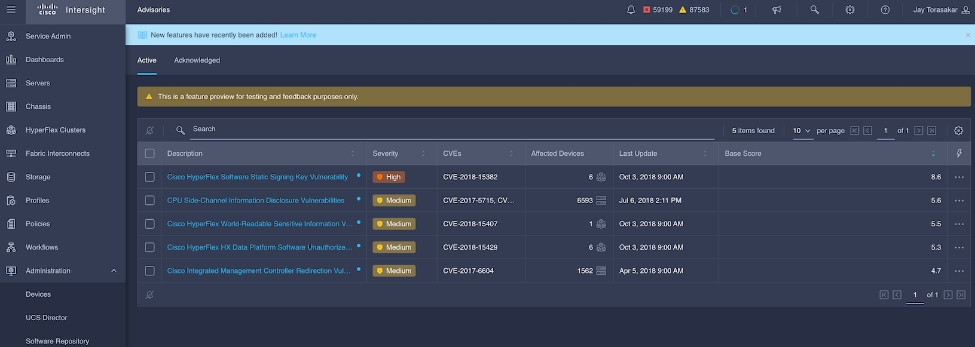
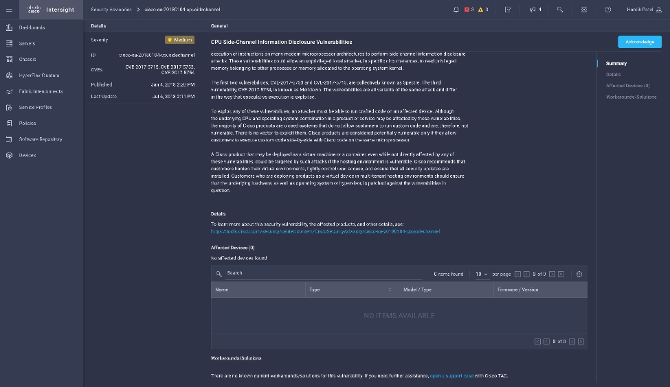
Cisco Intersight sources critical security advisories from the Cisco Security Advisory service to alert users about the endpoint devices that are impacted by the advisories and deferrals. These alerts are displayed as Advisories in Intersight. The Cisco Security Advisory service identifies and monitors and updates the status of the advisories to provide the latest information on the impacted devices, the severity of the advisory, the impacted products, and any available workarounds. If there are no known workarounds, you can open a support case with Cisco TAC for further assistance. A list of the security advisories is shown in Intersight under Advisories.
Figure 22. Intersight Dashboard
![]()
Figure 23. Example: List of PSIRTs Associated with Sample Intersight Account
CDP is an integrated data platform that is easy to deploy, manage, and use. By simplifying operations, CDP reduces the time to onboard new use cases across the organization. It uses machine learning to intelligently auto scale workloads up and down for more cost-effective use of cloud infrastructure.
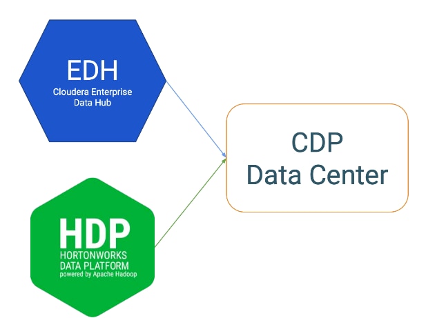
Cloudera Data Platform Private Cloud Base (CDP PvC Base) is the on-premises version of Cloudera Data Platform. This new product combines the best of both world, Cloudera Enterprise Data Hub and Hortonworks Data Platform Enterprise along with new features and enhancements across the stack. This unified distribution is a scalable and customizable platform where you can securely run many types of workloads.
Figure 24. Cloudera Data Platform – Unity Release
Cloudera Data Platform provides:
● Unified Distribution: Whether you are coming from CDH or HDP, CDP caters both. It offers richer feature sets and bug fixes with concentrated development and higher velocity.
● Hybrid and On-prem: Hybrid and multi-cloud experience, on-prem it offers best performance, cost, and security. It is designed for data centers with optimal infrastructure.
● Management: It provides consistent management and control points for deployments.
● Consistency: Security and governance policies can be configured once and applied across all data and workloads.
● Portability: Policies stickiness with data, even if it moves across all supported infrastructure.
Cloudera Data Platform Private Cloud Base (CDP PvC Base)
CDP Private Cloud Base is the on-premises version of Cloudera Data Platform. This new product combines the best of Cloudera Enterprise Data Hub and Hortonworks Data Platform Enterprise along with new features and enhancements across the stack. This unified distribution is a scalable and customizable platform where you can securely run many types of workloads.
CDP Private Cloud Base supports a variety of hybrid solutions where compute tasks are separated from data storage and where data can be accessed from remote clusters, including workloads created using CDP Private Cloud Experiences. This hybrid approach provides a foundation for containerized applications by managing storage, table schema, authentication, authorization, and governance.
CDP Private Cloud Base is comprised of a variety of components such as Apache HDFS, Apache Hive 3, Apache HBase, and Apache Impala, along with many other components for specialized workloads. You can select any combination of these services to create clusters that address your business requirements and workloads. Several pre-configured packages of services are also available for common workloads.
Cloudera Data Platform Private Cloud Experiences (CDP PVC Experiences)
Cloudera Data Platform (CDP) Private Cloud is the newest on-prem offering of CDP that brings many of the benefits of the public cloud deployments to the on-prem CDP deployments.
CDP Private Cloud provides a disaggregation of compute and storage and allows independent scaling of compute and storage clusters. Through the use of containerized applications deployed on Kubernetes, CDP Private Cloud brings both agility and predictable performance to analytic applications. CDP Private Cloud gets unified security, governance, and metadata management through Cloudera Shared Data Experience (SDX), which is available on a CDP Private Cloud Base cluster.
CDP Private Cloud users can rapidly provision and deploy Cloudera Data Warehousing and Cloudera Machine Learning services through the Management Console, and easily scale them up or down as required.
Shadow IT can now be eliminated when the CDP Private Cloud is implemented in Cisco Data Intelligence Platform. CDP Private Cloud offers cloud-like experience in customer’s on-prem environment. With disaggregated compute and storage, complete self-service analytics environment can be implemented, thereby, offering better infrastructure utilization.
Also, CDP Private Cloud offers personas driven approach such as Data Scientist, Data Engineer, and Data Analyst, thus providing the right tools to the users and improving time-to-value.
![]() This CVD doesn’t include Cloudera Data Platform Private Cloud Experiences; it’s explained in detail here: Cisco Data Intelligence Platform with Cloudera Data Platform Private Cloud Experiences
This CVD doesn’t include Cloudera Data Platform Private Cloud Experiences; it’s explained in detail here: Cisco Data Intelligence Platform with Cloudera Data Platform Private Cloud Experiences
Containerization
Hadoop 3.0 introduced production-ready Docker container support on YARN with GPU isolation and scheduling. This provided a plethora of opportunities for modern applications, such as micro-services and distributed applications frameworks comprised of 1000s of containers to run AI/ML algorithms on peta bytes of data quickly and easily.
With Cloudera Data Platform Private Cloud Experiences, Hadoop workloads can be run as containers on Kubernetes (powered by Red Hat OpenShift Container Platform) allowing disaggregated architecture and cloud native architecture in Hadoop.
![]() This CVD doesn’t include Containerization; it’s explained in detail here: Cisco Data Intelligence Platform with Cloudera Data Platform Private Cloud Experiences
This CVD doesn’t include Containerization; it’s explained in detail here: Cisco Data Intelligence Platform with Cloudera Data Platform Private Cloud Experiences
Distributed Deep Learning with Apache Submarine
Hadoop community initiated the Apache Submarine project to make distributed deep learning/machine learning applications easily launched, managed, and monitored. These improvements make distributed deep learning/machine learning applications (such as TensorFlow) run on Apache Hadoop YARN, Kubernetes, or just a container service. It enables data scientists to focus on algorithms instead of worrying about underlying infrastructure. Apache Submarine Workbench (work in progress) is a WEB system for data scientists where they can interactively access notebooks, submit/manage jobs, manage models, create model training workflows, access data sets, and more.
![]() This CVD doesn’t include Distributed Deep Learning. AI workloads on GPU are expected to be supported in future releases of Cloudera Data Platform.
This CVD doesn’t include Distributed Deep Learning. AI workloads on GPU are expected to be supported in future releases of Cloudera Data Platform.
Apache Spark 3.0
Apache Spark 3.0 is a highly anticipated release. To meet this expectation, Spark is no longer limited just to CPU for its workload, it now offers GPU isolation and pooling GPUs from different servers to accelerate compute. To easily manage the deep learning environment, YARN launches the Spark 3.0 applications with GPU. This prepares the other workloads, such as Machine Learning and ETL, to be accelerated by GPU for Spark Workloads. Cisco Blog on Apache Spark 3.0
![]() GPU support isn’t included in this release of Cloudera Data Platform. It is expected to be supported in future releases.
GPU support isn’t included in this release of Cloudera Data Platform. It is expected to be supported in future releases.
Red Hat OpenShift Container Platform (RHOCP) Cluster
Cloudera has selected Red Hat OpenShift as the preferred container platform for CDP Private Cloud. With Red Hat OpenShift, CDP Private Cloud delivers powerful, self-service analytics and enterprise-grade performance with the granular security and governance policies that IT leaders demand.
To keep pace in the digital era, businesses must modernize their data strategy for increased agility, ease-of-use, and efficiency. Together, Red Hat OpenShift and CDP Private Cloud help create an essential hybrid, multi-cloud data architecture, enabling teams to rapidly onboard mission-critical applications and run them anywhere, without disrupting existing ones.
![]() This CVD doesn’t include Cloudera Data Platform Private Cloud Experiences and the required Red Hat OpenShift Container Platform to power the Kubernetes. This is explained here: Cisco Data Intelligence Platform with Cloudera Data Platform Private Cloud Experiences
This CVD doesn’t include Cloudera Data Platform Private Cloud Experiences and the required Red Hat OpenShift Container Platform to power the Kubernetes. This is explained here: Cisco Data Intelligence Platform with Cloudera Data Platform Private Cloud Experiences
Kubernetes
Extracting intelligence from data lake in a timely and speedy fashion is an absolute necessity in finding emerging business opportunities, accelerating time to market efforts, gaining market share, and by all means, increasing overall business agility.
In today’s fast-paced digitization, Kubernetes enables enterprises to rapidly deploy new updates and features at scale while maintaining environmental consistency across test/dev/prod. Kubernetes provides the foundation for cloud-native apps which can be packaged in container images and can be ported to diverse platforms. Containers with microservice architecture managed and orchestrated by Kubernetes help organizations embark on a modern development pattern. Moreover, Kubernetes has become in fact, the standard for container orchestration and offers the core for on-prem container cloud for enterprises. it's a single cloud-agnostic infrastructure with a rich open-source ecosystem. It allocates, isolates, and manages resources across many tenants at scale as needed in elastic fashion, thereby, giving efficient infrastructure resource utilization. Figure 25 illustrates how Kubernetes is transforming the use of compute and becoming the standard for running applications.
Figure 25. Compute on Kubernetes is exciting!!!
![]() Not all features mentioned above are available as a generally available product for a data lake but holds the potential for the above capabilities.
Not all features mentioned above are available as a generally available product for a data lake but holds the potential for the above capabilities.
Spark on Kubernetes
With Spark 2.4.5 along with YARN as a scheduler, comes full support for Apache Spark on Kubernetes as a scheduler. This enables a Kubernetes cluster act as compute layer running Spark workloads for the data lake much of which is used in Cloudera Private Cloud applications.
Spark on Kubernetes has considerably advanced the Hadoop ecosystem, since it made it easier for many public cloud-specific applications and framework use cases to be deployed on-prem; thus, providing hybridity to stretch to cloud anywhere. Kubernetes address gaps that existed in YARN such as lack of isolation and reproducibility and allows workloads to be packaged in docker images. Spark on Kubernetes also inherit all other in-built features such as auto-scaling, detailed metrics, advanced container networking, security, and so on.
Hybrid Architecture
Red Hat OpenShift, container cloud platform for CDP private cloud and, is the market leading Kubernetes powered container platform. This combination is the first enterprise data cloud with a powerful hybrid architecture that decouples compute and storage for greater agility, ease-of-use, and more efficient use of private and multi-cloud infrastructure resources. With Cloudera’s Shared Data Experience (SDX), security and governance policies can be easily and consistently enforced across data and analytics in private as well as multi-cloud deployments. This hybridity will open myriad opportunities for multi-function integration with other frameworks such as streaming data, batch workloads, analytics, data pipelining/engineering, and machine learning.
Cloud Native Architecture for Data Lake and AI
Cisco Data Intelligence Platform with CDP private cloud accelerates the process of becoming cloud-native for your data lake and AI/ML workloads. By leveraging Kubernetes powered container cloud, enterprises can now quickly break the silos in monolithic application frameworks and embrace a continuous innovation of micro-services architecture with CI/CD approach. With cloud-native ecosystem, enterprises can build scalable and elastic modern applications that extends the boundaries from private cloud to hybrid.
Infrastructure and Software Requirements
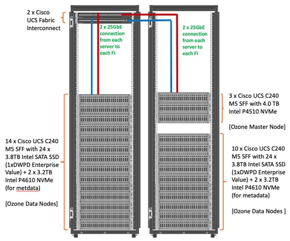
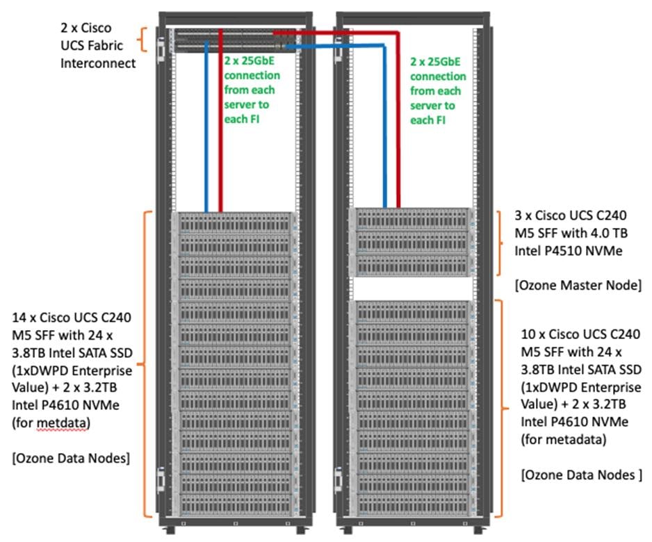
As illustrated in Figure 26, this CVD was designed with 27 x Cisco UCS C240 M5 running Cloudera Data Platform Private Cloud Base with Apache Ozone.
The cluster configuration consists of the following:
● 2 Cisco UCS 6454 Fabric Interconnects
● 27 Cisco UCS C240 M5 Rack servers
● 2 Cisco R42610 standard racks
● 4 Vertical Power distribution units (PDUs) (Country Specific)
The single-rack consists of two vertical PDUs and two Cisco UCS Fabric Interconnect with 16 Cisco UCS C240 M5 Rack Servers connected to each of the vertical PDUs for redundancy. This ensures availability during power source failure. Figure 26 illustrates a 2x25 Gigabit Ethernet link from each server is connected to both Fabric Interconnects.
Figure 26. Cisco Data Intelligence Platform with Cloudera Data Platform Private Base Running Apache Ozone
![]() Please contact your Cisco representative for country-specific information.
Please contact your Cisco representative for country-specific information.
![]() The Cisco UCS VIC 1457 provides 10/25Gbps, and the Cisco UCS VIC 1497 provides 40/100Gbps connectivity for the Cisco UCS C-series rack server. For more information see: Cisco UCS C-Series Servers Managing Network Adapters.
The Cisco UCS VIC 1457 provides 10/25Gbps, and the Cisco UCS VIC 1497 provides 40/100Gbps connectivity for the Cisco UCS C-series rack server. For more information see: Cisco UCS C-Series Servers Managing Network Adapters.
![]() In this solution, we configure quad-port mLOM VIC 1457 installed in Cisco UCS C240 M5 server with link 1-2 connected to Fabric A and link 3-4 connected to Fabric B to achieve 50GbE per server.
In this solution, we configure quad-port mLOM VIC 1457 installed in Cisco UCS C240 M5 server with link 1-2 connected to Fabric A and link 3-4 connected to Fabric B to achieve 50GbE per server.
![]() NVMe for Apache Ozone metadata is configured in RAID1 to provide business continuity in case of hard-ware failure. This is not needed on pure compute nodes which only use them for caching. Master Nodes and Data Nodes uses NVMe to store Ozone metadata. The Compute Nodes uses NVMe for shuffle and can be in JBOD. The mixed Compute Data Nodes uses NVMe for both Apache Ozone metadata and shuffle which requires mount Ozone partitions across both drives as RAID1 (800GB), with the remaining space used for shuffle/cache as independent JBOD partitions.
NVMe for Apache Ozone metadata is configured in RAID1 to provide business continuity in case of hard-ware failure. This is not needed on pure compute nodes which only use them for caching. Master Nodes and Data Nodes uses NVMe to store Ozone metadata. The Compute Nodes uses NVMe for shuffle and can be in JBOD. The mixed Compute Data Nodes uses NVMe for both Apache Ozone metadata and shuffle which requires mount Ozone partitions across both drives as RAID1 (800GB), with the remaining space used for shuffle/cache as independent JBOD partitions.
Port Configuration on Cisco UCS Fabric Interconnect 6454
Table 4 lists the port configuration on Cisco UCS Fabric Interconnect 6454.
Table 4. Port Configuration on Cisco UCS Fabric Interconnect 6454
| Port Type |
Port Number |
| Server |
1 - 48 |
| Network |
49 - 54 |
Server Configuration and Cabling for Cisco UCS C240 M5
The Cisco UCS C240 M5 Rack Server is equipped with two 2nd Gen Intel Xeon Scalable Family Processor 6230R (2 x 26 cores, 2.1 GHz), 384 GB of memory (12 x 32GB @ 2933MHz), Cisco UCS Virtual Interface Card 1497, 4 x 3.8TB 2.5-inch Enterprise Value 6G SATA SSD (Intel S4500/S4150), M.2 with 2 x 960GB SSDs for Boot.
Figure 27 illustrates the port connectivity between the Cisco UCS Fabric Interconnect 6454 and Cisco UCS C240 M5 Rack Server with mLOM VIC 1457. Sixteen Cisco UCS C240 M5 servers are installed in this configuration.
For information on physical connectivity and single-wire management, go to: https://www.cisco.com/c/en/us/td/docs/unified_computing/ucs/c-series_integration/ucsm4-0/b_C-Series-Integration_UCSM4-0/b_C-Series-Integration_UCSM4-0_chapter_01.html
Figure 27. Network Connectivity for Cisco UCS C240 M5 Rack Server
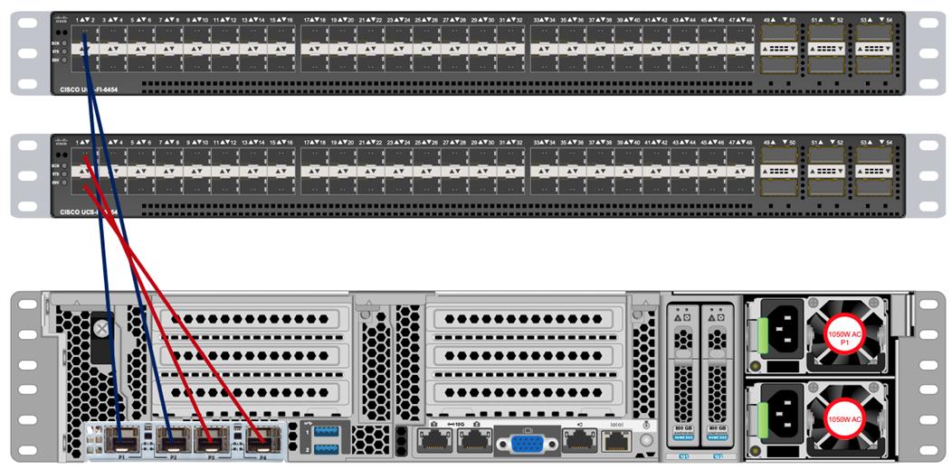
![]() With Cisco UCS VIC 1455 and 1457, by default a port-channel is turned on between port 1-2 and port-channel between port 3-4. Up to 14 additional vHBAs or vNICs can be created.
With Cisco UCS VIC 1455 and 1457, by default a port-channel is turned on between port 1-2 and port-channel between port 3-4. Up to 14 additional vHBAs or vNICs can be created.
![]() When port-channel mode is set to enabled, the ports on the Cisco Nexus switch should be configured as channel group members.
When port-channel mode is set to enabled, the ports on the Cisco Nexus switch should be configured as channel group members.
![]() The Cisco UCS 1455 and 1457 Virtual Interface Cards, in non-port channel mode, provide four vHBAs and four vNICs by default. Up to 10 additional vHBAs or vNICs can be created.
The Cisco UCS 1455 and 1457 Virtual Interface Cards, in non-port channel mode, provide four vHBAs and four vNICs by default. Up to 10 additional vHBAs or vNICs can be created.
![]() As a best practice, select port 1 and 3 to connect to a pair of Cisco Nexus switch, port 2 and 4 can be added without the need for any additional changes if desired.
As a best practice, select port 1 and 3 to connect to a pair of Cisco Nexus switch, port 2 and 4 can be added without the need for any additional changes if desired.
![]() Switching between port-channel mode on/off requires server reboot.
Switching between port-channel mode on/off requires server reboot.
![]() For detailed configuration through Intersight see https://www.intersight.com/help/resources/creating_network_policies
For detailed configuration through Intersight see https://www.intersight.com/help/resources/creating_network_policies
Software Distributions and Firmware Versions
The software distributions required versions are listed in Table 5.
Table 5. Software Distribution and Version
| Layer |
Component |
Version or Release |
| Compute |
Cisco UCS C240 M5 |
4.1(3b) |
| Network |
Cisco UCS Fabric Interconnect |
4.1(3b) |
| Cisco UCS VIC1497 Firmware |
5.1(3a) |
|
| Storage |
Cisco 12G Modular RAID Controller |
51.10.0-3612 |
| SAS Expander |
65.11.20.00 |
|
| LSI MegaRAID SAS Driver |
07.710.50.00-rh1 |
|
| Software |
Red Hat Enterprise Linux Server |
7.8 |
| Cloudera CDP Private Cloud Base |
7.1.5 |
|
| Hadoop |
3.1.1 |
|
| Spark |
2.4.5 |
![]() The latest drivers can be downloaded from here: https://software.cisco.com/download/home/283862063/type/283853158/release/4.1(3b)
The latest drivers can be downloaded from here: https://software.cisco.com/download/home/283862063/type/283853158/release/4.1(3b)
![]() The latest drivers can be downloaded from the link below: https://software.cisco.com/download/home/283862063/type/283853158/release/4.1(3b)
The latest drivers can be downloaded from the link below: https://software.cisco.com/download/home/283862063/type/283853158/release/4.1(3b)
Deployment Hardware and Software
Cisco Unified Computing System Configuration
This section details the Cisco Unified Computing System (Cisco UCS) configuration that was done as part of the infrastructure build out. The racking, power, and installation of the Cisco UCS Rack Server is described in the physical topology section earlier in this document. Please refer to the Cisco UCS Manager Getting Started Guide. For more information about each step, see the Cisco UCS Manager - Configuration Guides.
Configure Cisco UCS Fabric Interconnect
This document assumes you are using Cisco UCS Manager Software version 4.1(3b). To upgrade the Cisco UCS Manager software and the Cisco UCS 6454 Fabric Interconnect software to a higher version of the firmware, see the Cisco UCS Manager Install and Upgrade Guides.
Alternatively, if you intend to clear the existing Cisco UCS Manager configuration, follow these steps:
1. Connect a console cable to the console port on what will become the primary fabric interconnect.
2. If the fabric interconnects were previously deployed and you want to erase it to redeploy, follow these steps:
3. Login with the existing username and password.
4. #connect local-mgmt
5. #erase config
6. #yes (to confirm)
7. After the fabric interconnect restarts, the out-of-box first time installation prompt appears, type console and press Enter.
8. Follow the Initial Configuration steps as outlined in Cisco UCS Manager Getting Started Guide. When configured, log into UCSM IP Address via the web interface to perform the base Cisco UCS configuration.
Configure Fabric Interconnects for a Cluster Setup
To configure the Cisco UCS Fabric Interconnects, follow this step:
1. Verify the following physical connections on the fabric interconnect:
● The management Ethernet port (mgmt0) is connected to an external hub, switch, or router.
● The L1 ports on both fabric interconnects are directly connected to each other.
● The L2 ports on both fabric interconnects are directly connected to each other
Configure Fabric Interconnect A
To configure Fabric Interconnect A, follow these steps:
1. Connect to the console port on the first Cisco UCS 6454 Fabric Interconnect.
At the prompt to enter the configuration method, enter console to continue.
If asked to either perform a new setup or restore from backup, enter setup to continue.
Enter y to continue to set up a new Fabric Interconnect.
Enter y to enforce strong passwords.
2. Enter the password for the admin user.
3. Enter the same password again to confirm the password for the admin user.
When asked if this fabric interconnect is part of a cluster, answer y to continue.
Enter A for the switch fabric.
4. Enter the cluster name for the system name.
5. Enter the Mgmt0 IPv4 address.
6. Enter the Mgmt0 IPv4 netmask.
7. Enter the IPv4 address of the default gateway.
8. Enter the cluster IPv4 address.
To configure DNS, answer y.
9. Enter the DNS IPv4 address.
Answer y to set up the default domain name.
10. Enter the default domain name.
Review the settings that were printed to the console, and if they are correct, answer yes to save the configuration.
11. Wait for the login prompt to make sure the configuration has been saved.
Configure Fabric Interconnect B
To configure Fabric Interconnect B, follow these steps:
1. Connect to the console port on the second Cisco UCS 6454 Fabric Interconnect.
When prompted to enter the configuration method, enter console to continue.
The installer detects the presence of the partner Fabric Interconnect and adds this fabric interconnect to the cluster. Enter y to continue the installation.
2. Enter the admin password that was configured for the first Fabric Interconnect.
3. Enter the Mgmt0 IPv4 address.
4. Answer yes to save the configuration.
5. Wait for the login prompt to confirm that the configuration has been saved.
For more information about configuring Cisco UCS 6454 Series Fabric Interconnect, go to: https://www.cisco.com/c/en/us/td/docs/unified_computing/ucs/ucs-manager/GUI-User-Guides/Getting-Started/4-0/b_UCSM_Getting_Started_Guide_4_0.html
To log into Cisco UCS Manager, follow these steps:
1. Open a Web browser and navigate to the Cisco UCS 6454 Fabric Interconnect cluster address.
2. Click the Launch link to download the Cisco UCS Manager software.
3. If prompted to accept security certificates, accept as necessary.
4. When prompted, enter admin for the username and enter the administrative password.
5. Click Login to log into the Cisco UCS Manager.
Upgrade Cisco UCS Manager Software to Version 4.1(3b)
This document assumes you’re using Cisco UCS 4.1(3b). Refer to the Cisco UCS 4.1 Release (upgrade Cisco UCS Manager software and Cisco UCS 6454 Fabric Interconnect software to version 4.1(3b). Also, make sure the Cisco UCS C-Series version 4.1(3b) software bundles are installed on the Fabric Interconnects.
![]() Upgrading Cisco UCS firmware is beyond the scope of this document. However for complete Cisco UCS Install and Upgrade Guides, go to: https://www.cisco.com/c/en/us/support/servers-unified-computing/ucs-manager/products-installation-guides-list.html
Upgrading Cisco UCS firmware is beyond the scope of this document. However for complete Cisco UCS Install and Upgrade Guides, go to: https://www.cisco.com/c/en/us/support/servers-unified-computing/ucs-manager/products-installation-guides-list.html
To register UCSM with Intersight, follow these steps:
1. Login WebUI for Cisco UCS Manager, go to admin tab. Select Device Connector from the drop-down list. Click Settings.
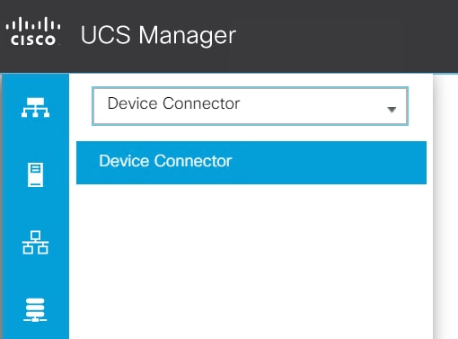
2. Enable Device Connector. Select Allow Control in Access Mode.
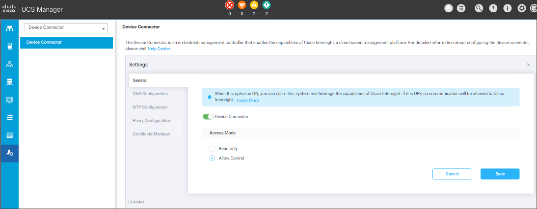
3. Complete steps for DNS configuration, NTP Configuration and Proxy Configuration as applicable. Click Save.
4. Make sure UCSM can communicate to Intersight.
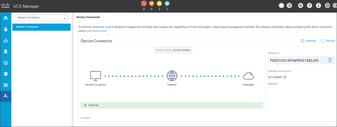
5. Copy Device Claim ID from right side of Device Connector screen.
6. Log into Intersight.com
7. Select Devices tab on the left side menu; click Claim a New Device.
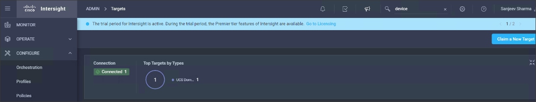
8. Enter Device ID and Device Claim Code copied from UCS Manager. Click Claim.
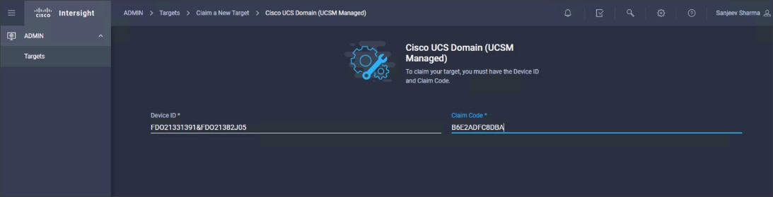
9. When Claimed, UCSM can be launched directly from Intersight.
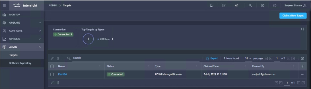
10. Click Launch UCSM.
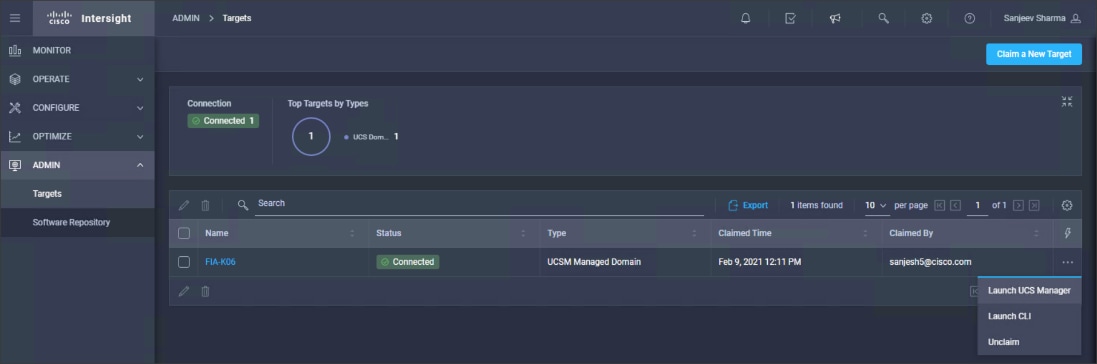
For more information, go to: Claiming a Device
![]() For this study, we launched UCSM through Intersight. UCSM WebUI can also be accessed the traditional way which is by entering the IP address of Cisco UCS Manager in a Web Browser. For more information, go to: https://www.cisco.com/c/en/us/td/docs/unified_computing/ucs/UCS_CVDs/Cisco_UCS_Data_Intelligence_Platform_with_Cloudera_and_CDSW.html
For this study, we launched UCSM through Intersight. UCSM WebUI can also be accessed the traditional way which is by entering the IP address of Cisco UCS Manager in a Web Browser. For more information, go to: https://www.cisco.com/c/en/us/td/docs/unified_computing/ucs/UCS_CVDs/Cisco_UCS_Data_Intelligence_Platform_with_Cloudera_and_CDSW.html
Configure Cisco UCS Manager through Intersight
To configure Cisco UCS Manager, follow these high-level steps:
1. Configure Fabric Interconnects for a Cluster Setup.
2. Set Fabric Interconnects to Fiber Channel End Host Mode.
3. Synchronize Cisco UCS to NTP.
4. Configure Fabric Interconnects for Rack or Chassis and Blade Server Discovery.
5. Configure Global Policies.
6. Configure Server Ports.
7. Configure LAN on Cisco UCS Manager.
8. Configure Ethernet LAN Uplink Ports.
9. Set QoS system class and Jumbo Frames in both the Cisco Fabric Interconnect.
10. Create Uplink Port Channels to Cisco Nexus Switches.
11. Configure FC SAN Uplink Ports
12. Configure VLAN
13. Configure IP, UUID, Server, MAC Pool and policy:
a. IP Pool Creation
b. UUID Suffix Pool Creation
c. Server Pool Creation
d. Configure Server BIOS Policy.
e. Create Adapter Policy.
f. Configure Default Maintenance Policy.
g. Configure vNIC Template
h. Create Server Boot Policy
Details for each step are discussed in the following sections.
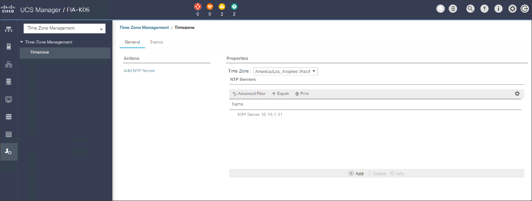
Synchronize Cisco UCSM to NTP
To synchronize the Cisco UCS environment to the NTP server, follow these steps:
1. In Cisco UCS Manager, in the navigation pane, click the Admin tab.
2. Select All > Time zone Management.
3. In the Properties pane, select the appropriate time zone in the Time zone menu.
4. Click Save Changes and then click OK.
5. Click Add NTP Server.
6. Enter the NTP server IP address and click OK.
7. Click OK to finish.
8. Click Save Changes.
Figure 28. Synchronize Cisco UCS Manager to NTP
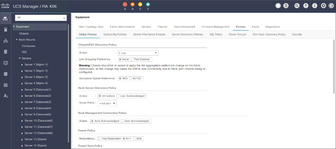
Configure Global Policies
The rack server and chassis discovery policy determine how the system reacts when you add a new rack server or chassis. We recommend using the platform max value as shown. Using platform max helps ensure that Cisco UCS Manager uses the maximum number of IOM uplinks available.
To configure the global policies, follow this step:
1. In Cisco UCS Manager; Configure Global Policy. Go to Equipment > Policies (right pane) > Global Policies.
Figure 29. Global Policies in UCSM
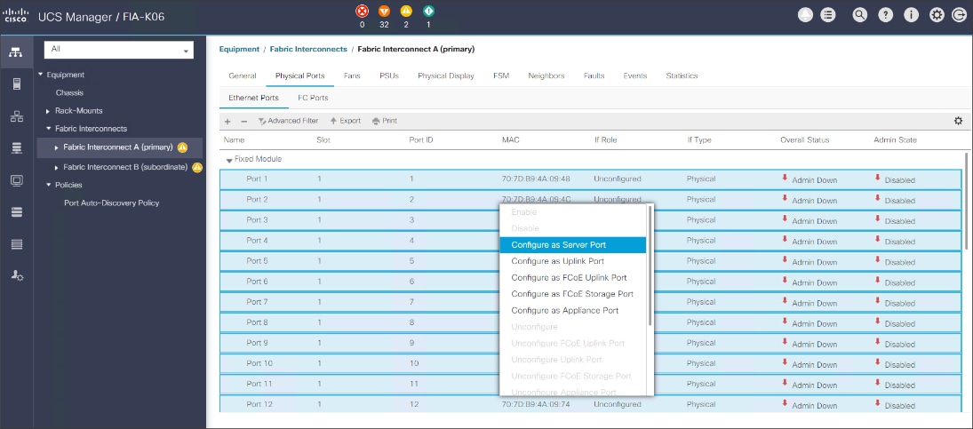
Configure Server Ports
Configure Server Ports to initiate Chassis and Blade discovery. To configure server ports, follow these steps:
1. Go to Equipment > Fabric Interconnects > Fabric Interconnect A > Fixed Module > Ethernet Ports.
2. Select the ports (for this solution ports are 1-28) which are connected to the Cisco UCS VIC 1457 on Cisco UCS C240 M5 rack server.
3. Right-click and select Configure as Server Port.
Figure 30. Configure Server Port on Cisco UCS Manager Fabric Interconnect for Server/Chassis Discovery
Configure Uplink Ports
Configure Network Ports to connect to the data center network switch.
![]() In our solution study, we connected to a Cisco Nexus 9000 series switch.
In our solution study, we connected to a Cisco Nexus 9000 series switch.
To configure Network ports, follow these steps:
1. Go to Equipment > Fabric Interconnects > Fabric Interconnect A > Fixed Module > Ethernet Ports.
2. Select the ports (for this solution ports are 49-54) which are connected to the Cisco Nexus 9000 series switch for northbound network connectivity.
3. Right-click and select Configure as Network Port.
Figure 31. Configure Network Port on Cisco UCS Manager Fabric Interconnect
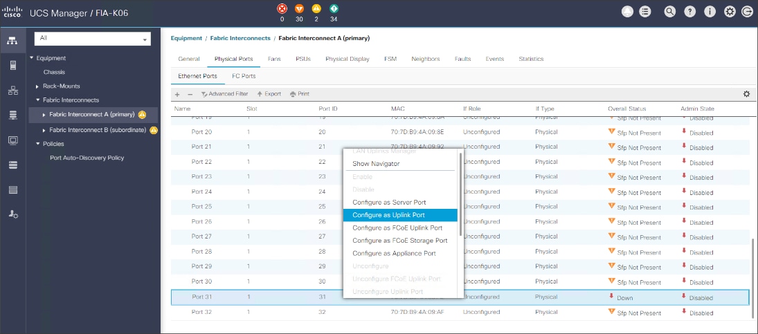
Create New Organization
To configure the necessary Organization for the Cisco UCS environment, follow these steps:
1. In Cisco UCS Manager, click the Servers tab in the navigation pane.
2. Select root > Sub-Organization.
3. Right-click, select Create Sub-Organization.
4. Enter the name of the Organization.
5. Click OK.
Figure 32. Create New Organization
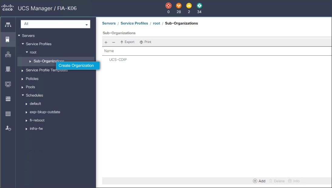
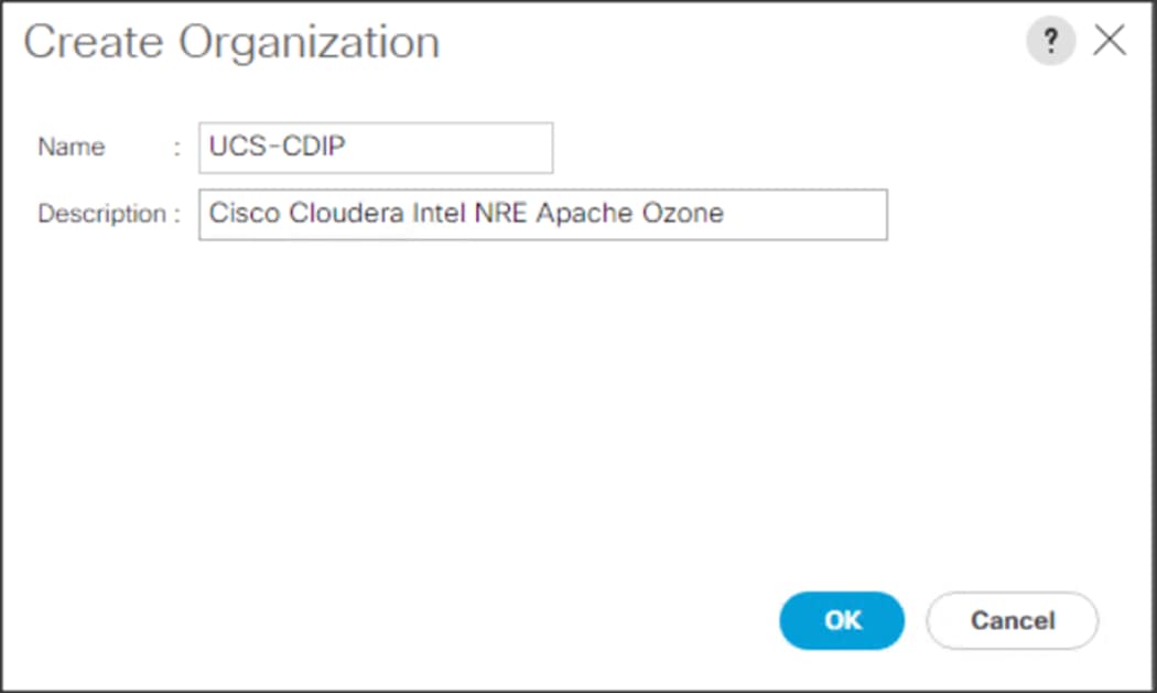
![]() Cisco UCS Manager pools and policies required for this solution were created under new CDIP-CDP Organization created.
Cisco UCS Manager pools and policies required for this solution were created under new CDIP-CDP Organization created.
Configure IP, UUID, Server and MAC Pools
IP Pool Creation
An IP address pool on the out-of-band management network must be created to facilitate KVM access to each compute node in the Cisco UCS domain. To create a block of IP addresses for server KVM access in the Cisco UCS environment, follow these steps:
1. In Cisco UCS Manager, in the navigation pane, click the LAN tab.
2. Select Pools > root > Sub-Organizations > CDIP-CDP> IP Pools > click Create IP Pool.
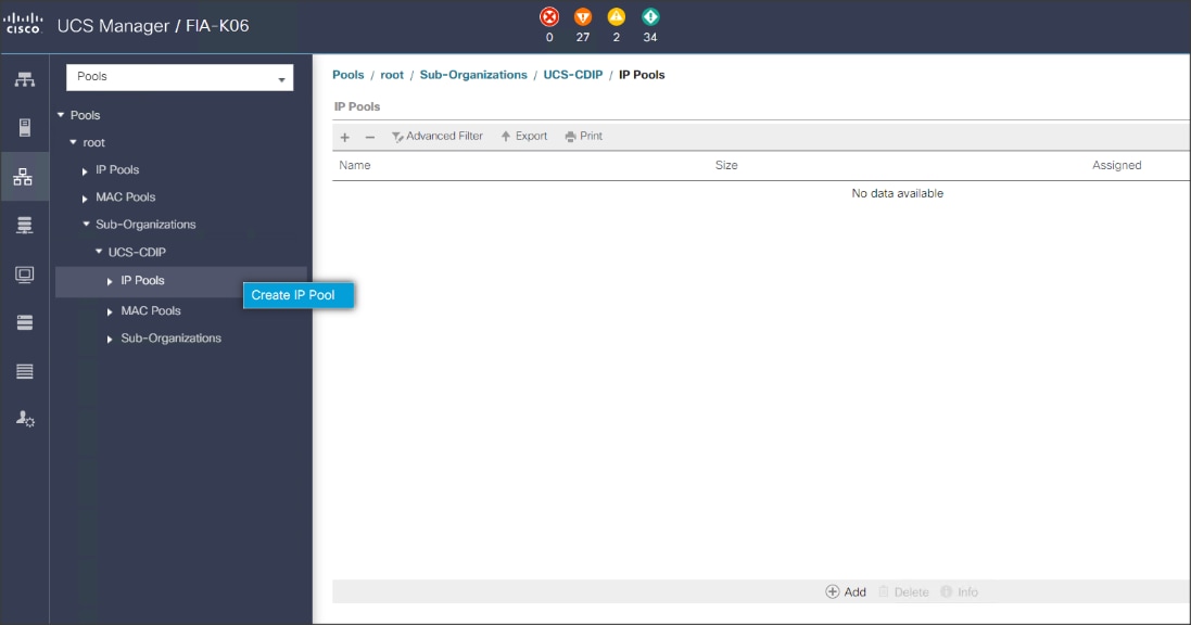
3. Enter name for the IP Pool, select option Sequential to assign IP in sequential order then click Next.
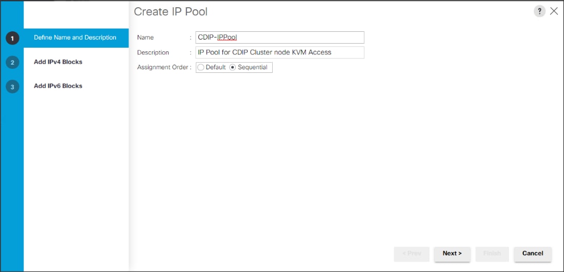
4. Click Add IPv4 Block.
5. Enter the starting IP address of the block and the number of IP addresses required, and the subnet and gateway information as shown below.
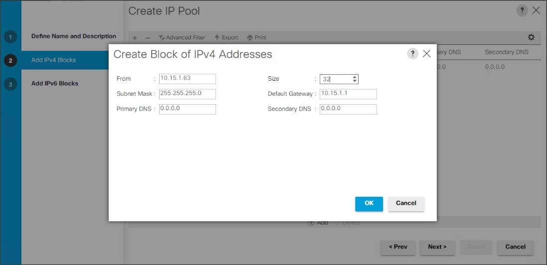
UUID Suffix Pool Creation
To configure the necessary universally unique identifier (UUID) suffix pool for the Cisco UCS environment, follow these steps:
1. In Cisco UCS Manager, click the Servers tab in the navigation pane.
2. Select Pools > root > Sub-Organization > CDIP-CDP.
3. Right-click UUID Suffix Pools and then select Create UUID Suffix Pool.
4. Enter the name of the UUID name.
5. Optional: Enter a description for the UUID pool.
6. Keep the prefix at the derived option and select Sequential in as Assignment Order then click Next.
Figure 33. UUID Suffix Pool Creation
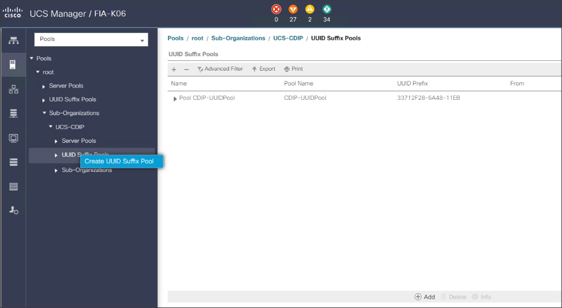
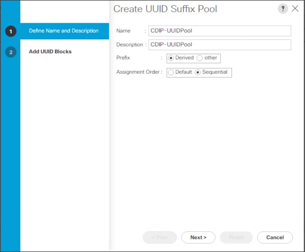
Figure 34. Create a Block of UUID Suffixes

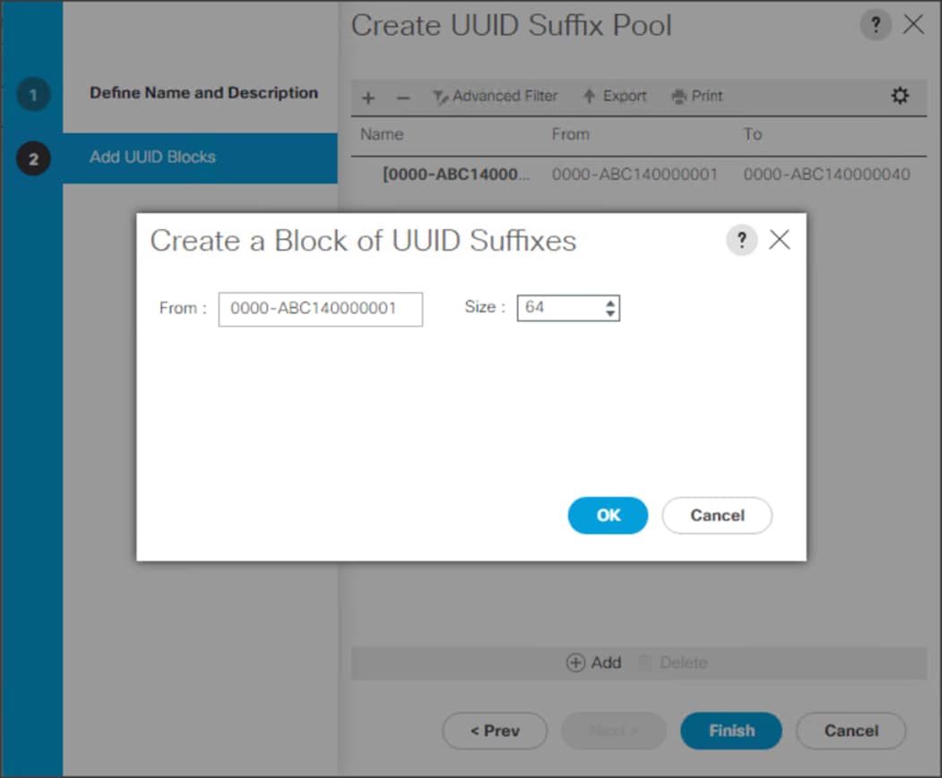
Server Pool Creation
To configure the necessary server pool for the Cisco UCS environment, follow these steps:
![]() Consider creating unique server pools to achieve the granularity that is required in your environment.
Consider creating unique server pools to achieve the granularity that is required in your environment.
1. In Cisco UCS Manager, click the Servers tab in the navigation pane.
2. Select Pools > root > Sub-Organization > CDIP-CDP > right-click Server Pools > Select Create Server Pool.
3. Enter name of the server pool.
4. Optional: Enter a description for the server pool then click Next.
Figure 35. Create Server Pool
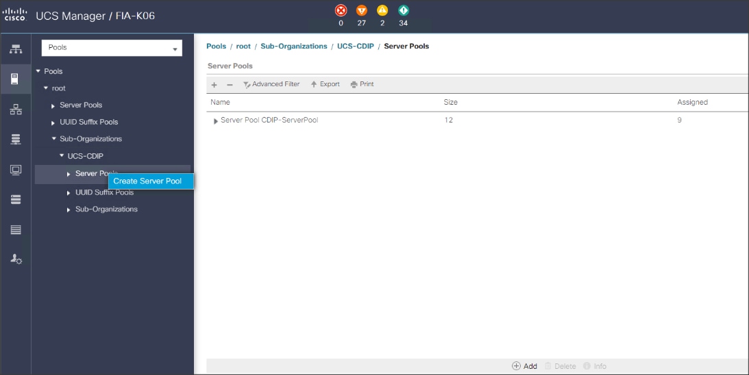
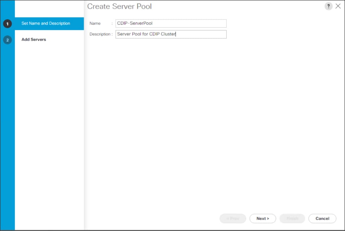
5. Select servers to be used for the deployment and click > to add them to the server pool. In our case we added thirty servers in this server pool.
6. Click Finish and then click OK.
Figure 36. Add Server in the Server Pool
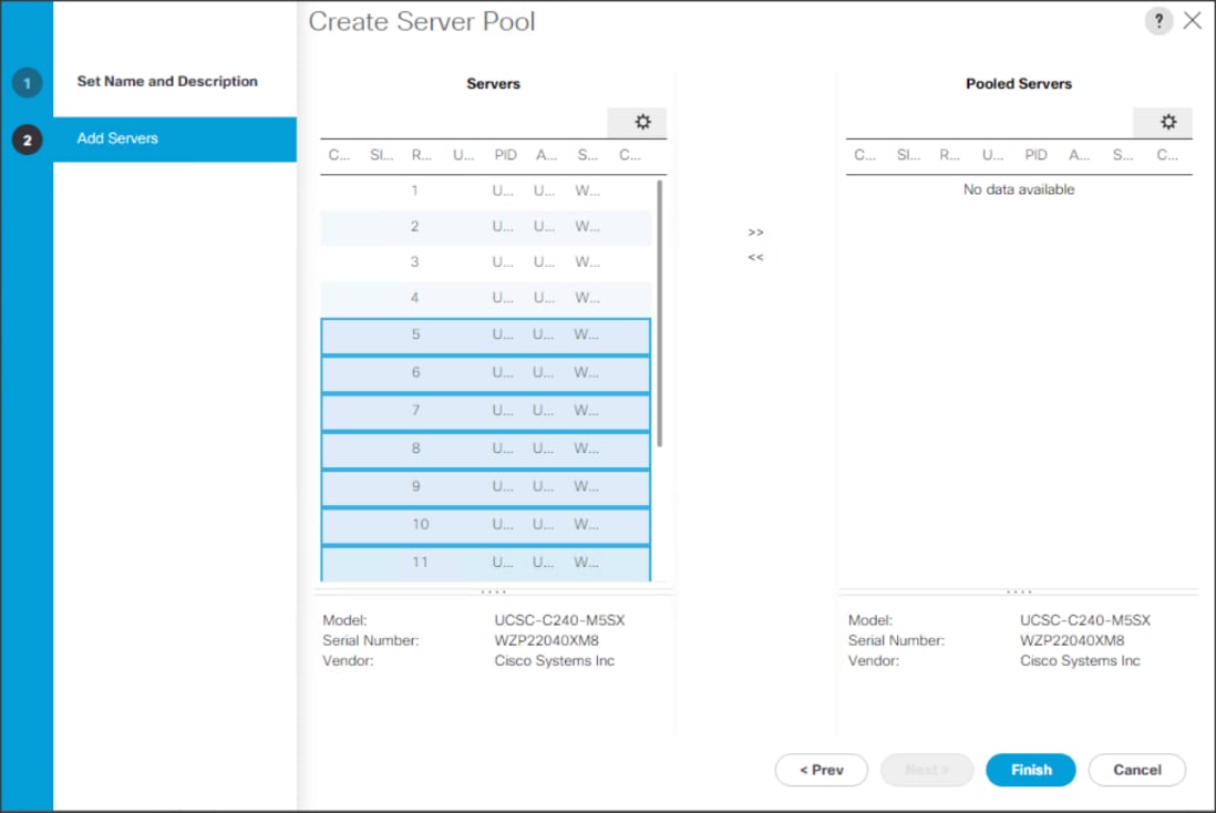
7. When the added Servers are in the Pooled servers, click Finish.
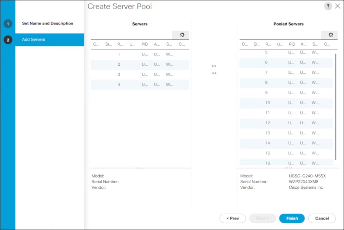
MAC Pool Creation
To configure the necessary MAC address pools for the Cisco UCS environment, follow these steps:
1. In Cisco UCS Manager, click the LAN tab in the navigation pane.
2. Select Pools > root > Sub-Organization > CDIP-CDP> right-click MAC Pools.
3. Select Create MAC Pool to create the MAC address pool.
4. Enter name for MAC pool. Select Assignment Order as Sequential.
5. Enter the seed MAC address and provide the number of MAC addresses to be provisioned.
6. Click OK and then click Finish.
7. In the confirmation message, click OK.
Figure 37. Creating a Block of MAC Addresses
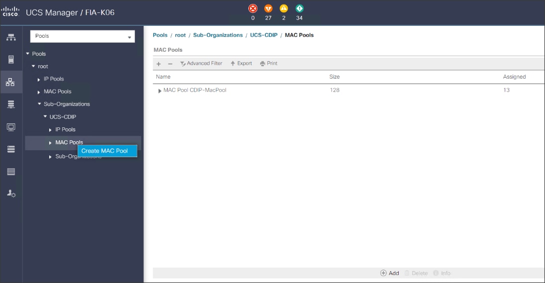
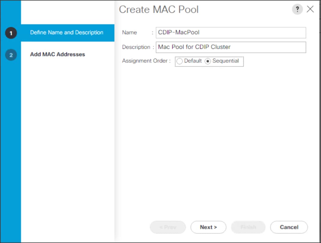
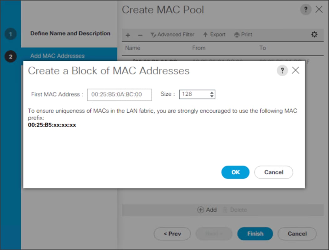
Configure VLAN
To configure the necessary virtual local area networks (VLANs) for the Cisco UCS environment, follow these steps:
1. In Cisco UCS Manager, click the LAN tab in the navigation pane.
2. Select LAN > LAN Cloud.
3. Right-click VLANs
4. Select Create VLANs
5. Enter the name of the VLAN to be used.
6. Keep the Common/Global option selected for the scope of the VLAN.
7. Enter <VLAN Number> as the ID of the VLAN ID.
8. Keep the Sharing Type as None.
Figure 38. Create VLAN
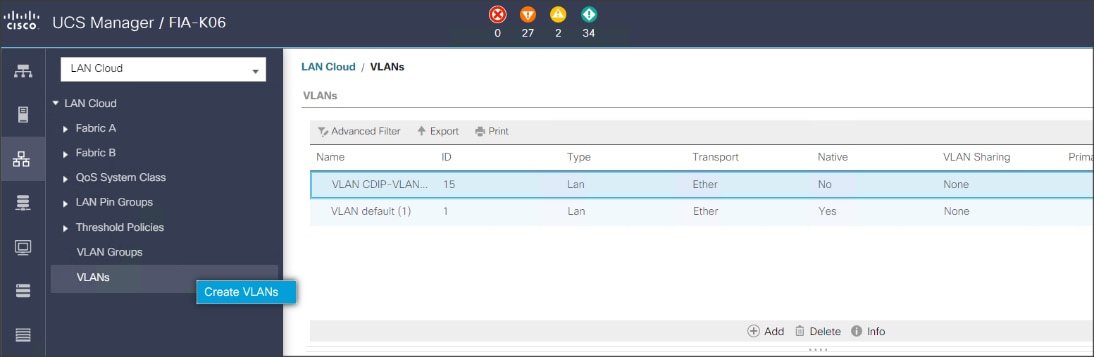
The NIC will carry the data traffic from VLAN13. A single vNIC is used in this configuration and the Fabric Failover feature in Fabric Interconnects will take care of any physical port down issues. It will be a seamless transition from an application perspective.
Figure 39. Create VLANs
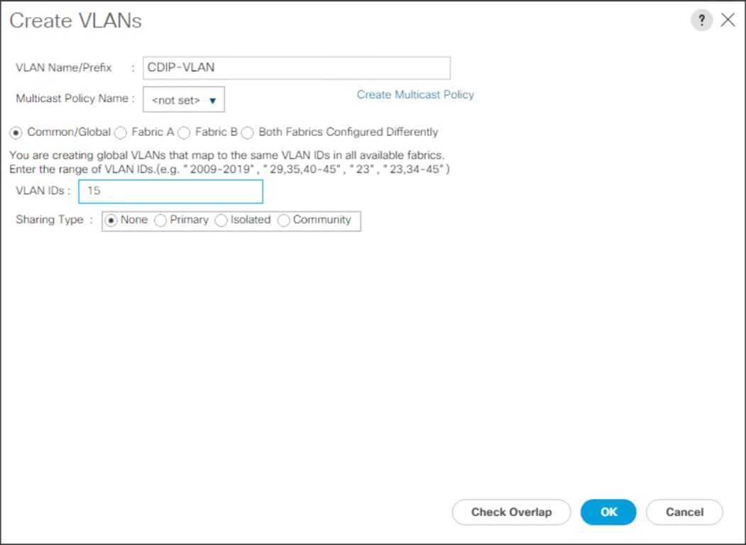
Set System Class QoS and Jumbo Frame in Both Cisco Fabric Interconnects
To configure jumbo frames and enable quality of service in the Cisco UCS fabric, follow these steps:
1. In Cisco UCS Manager, click the LAN tab in the navigation pane.
2. Select LAN > LAN Cloud > QoS System Class.
3. In the right pane, click the General tab.
4. On the Platinum row, enter 9216 in the box under the MTU column.
5. Click Save Changes.
6. Click OK.
![]() Changing the QoS system class MTU requires a reboot of Cisco UCS Fabric Interconnect for changes to be effective.
Changing the QoS system class MTU requires a reboot of Cisco UCS Fabric Interconnect for changes to be effective.
Figure 40. Configure System Class QoS on Cisco UCS Fabric Interconnects
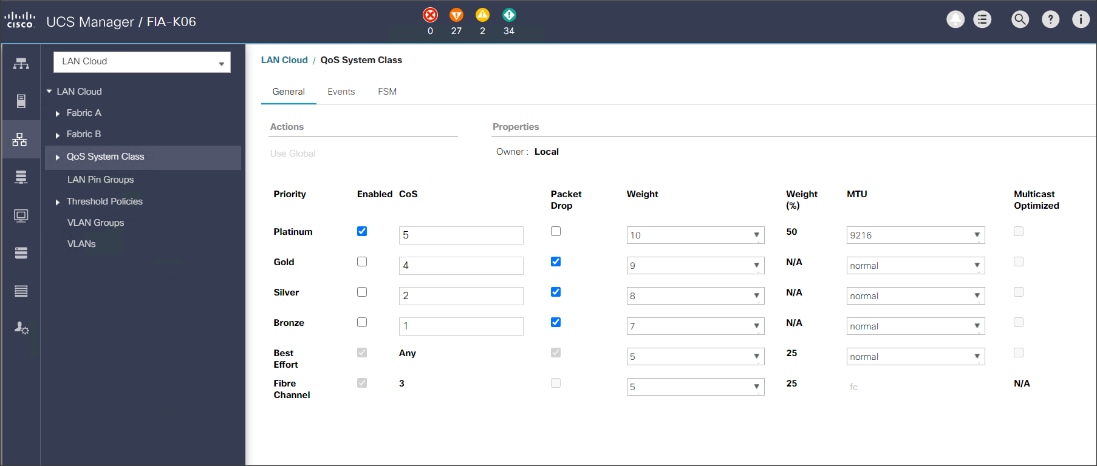
To create the QoS policy to assign priority based on the class using the Cisco UCS Manager GUI, follow these steps:
1. Select LAN tab in the left pane in the Cisco UCS Manager GUI.
2. Select LAN > Policies > root > CDIP-CDP> QoS Policies.
3. Right-click QoS Policies.
4. Select Create QoS Policy.
Figure 41. Create QoS Policy
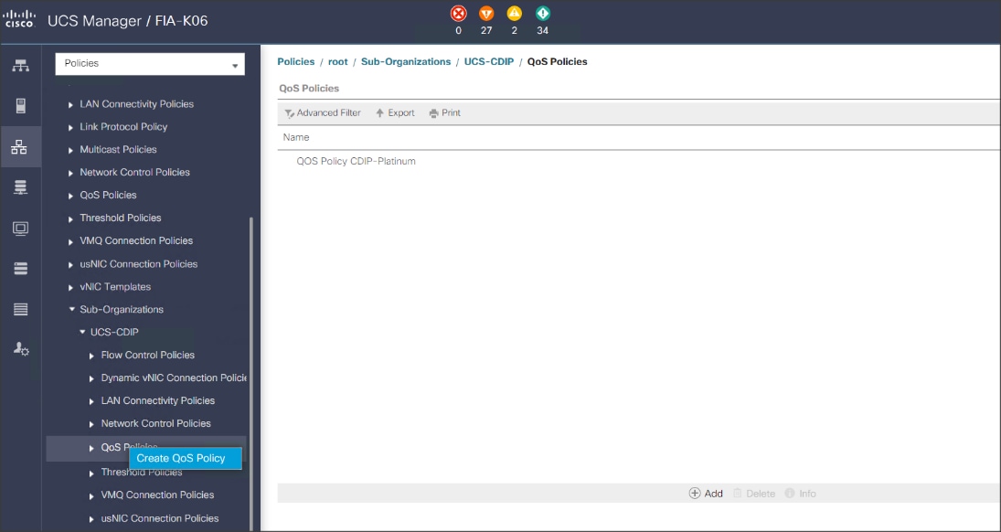
![]() We created a Platinum class QoS policy for this solution.
We created a Platinum class QoS policy for this solution.
Figure 42. Platinum QoS Policy
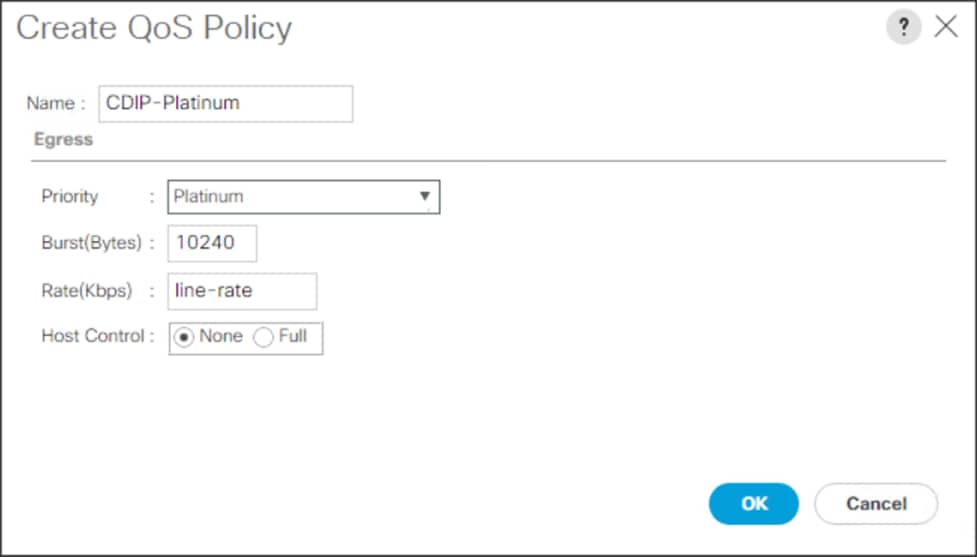
To create multiple virtual network interface card (vNIC) templates for the Cisco UCS environment, follow these steps:
1. In Cisco UCS Manager, click the LAN tab in the navigation pane.
2. Select Policies > root > Sub-Organization > CDIP-CDP> vNIC Template.
3. Right-click vNIC Templates.
4. Select Create vNIC Template.
5. Enter name for vNIC template.
6. Keep Fabric A selected. Select the Enable Failover checkbox.
7. Select Updating Template as the Template Type.
8. Under VLANs, select the checkboxes for desired VLANs to add as part of the vNIC Template.
9. Set Native-VLAN as the native VLAN.
10. For MTU, enter 9000.
11. In the MAC Pool list, select MAC Pool configured.
12. Select QOS policy created earlier.
13. Select default Network Control Policy.
14. Click OK to create the vNIC template.
Figure 43. Create the vNIC Template
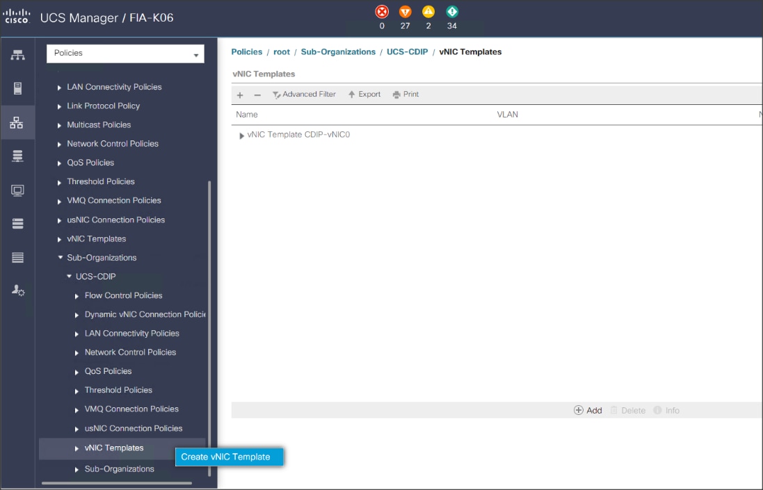
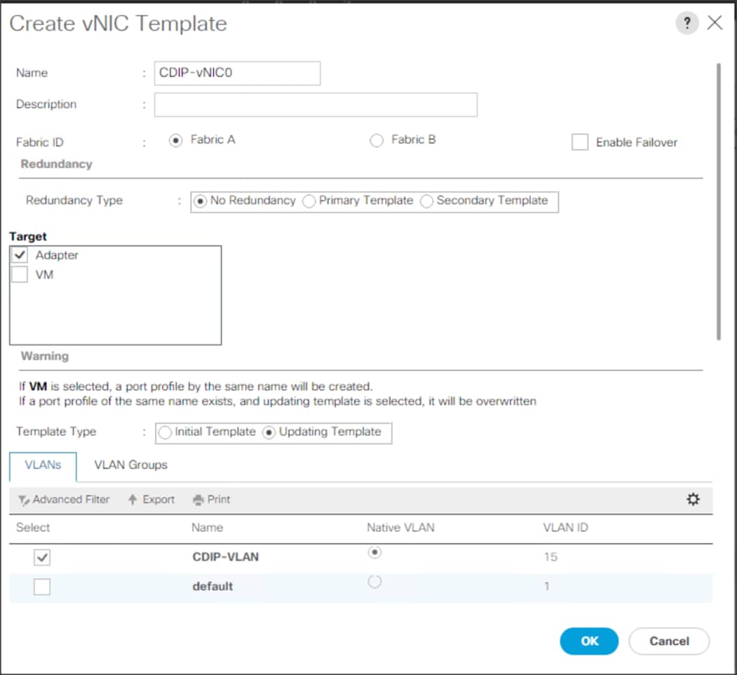
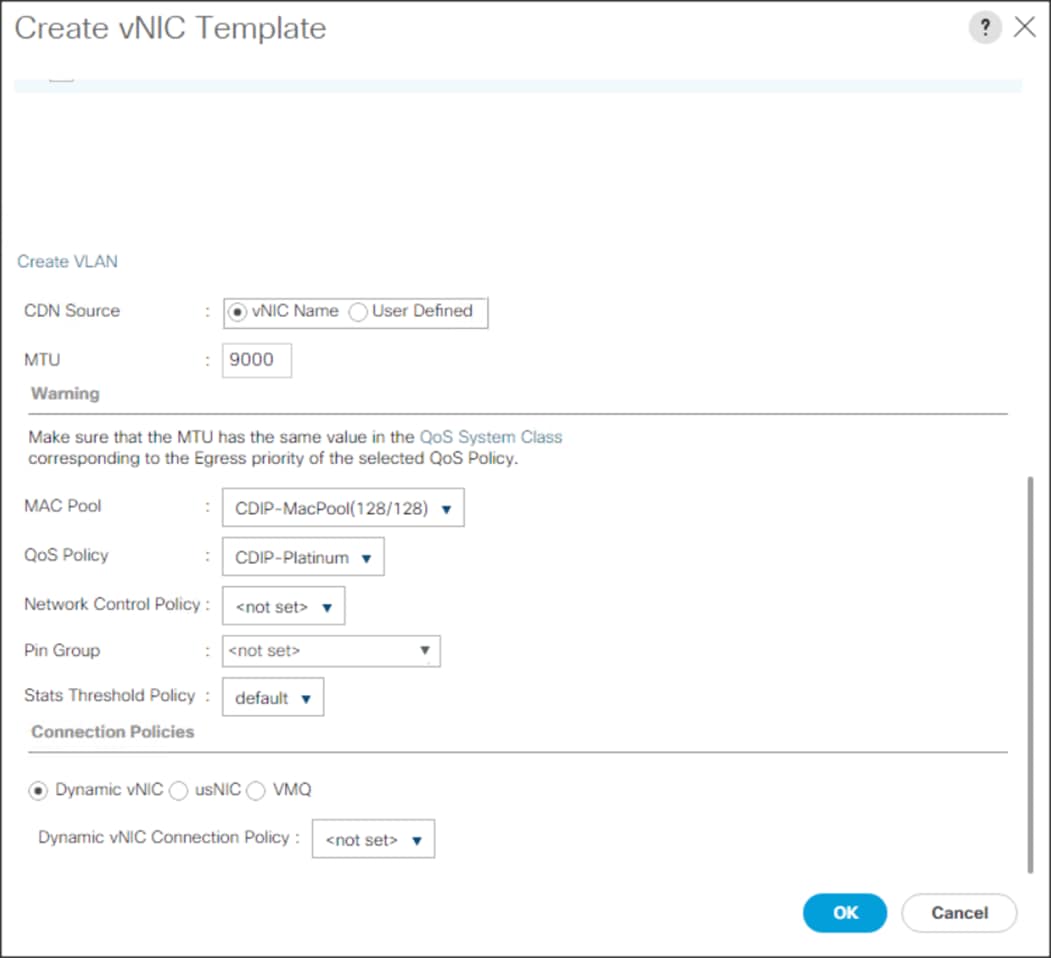
Firmware management policies allow the administrator to select the corresponding packages for a given server configuration. These policies often include packages for adapter, BIOS, board controller, FC adapters, host bus adapter (HBA) option ROM, and storage controller properties.
To create a firmware management policy for a given server configuration in the Cisco UCS environment, follow these steps:
1. In Cisco UCS Manager, click the Servers tab in the navigation pane.
2. Select Policies > root > Sub-Organization > CDIP-CDP> Host Firmware Packages.
3. Right-click Host Firmware Packages.
4. Select Create Host Firmware Package.
5. Enter name of the host firmware package.
6. Leave Simple selected.
7. Select the version.
8. Click OK to create the host firmware package.
Figure 44. Host Firmware Package
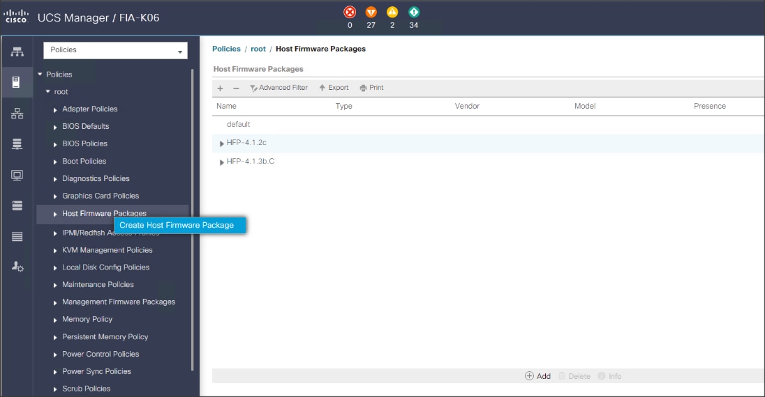
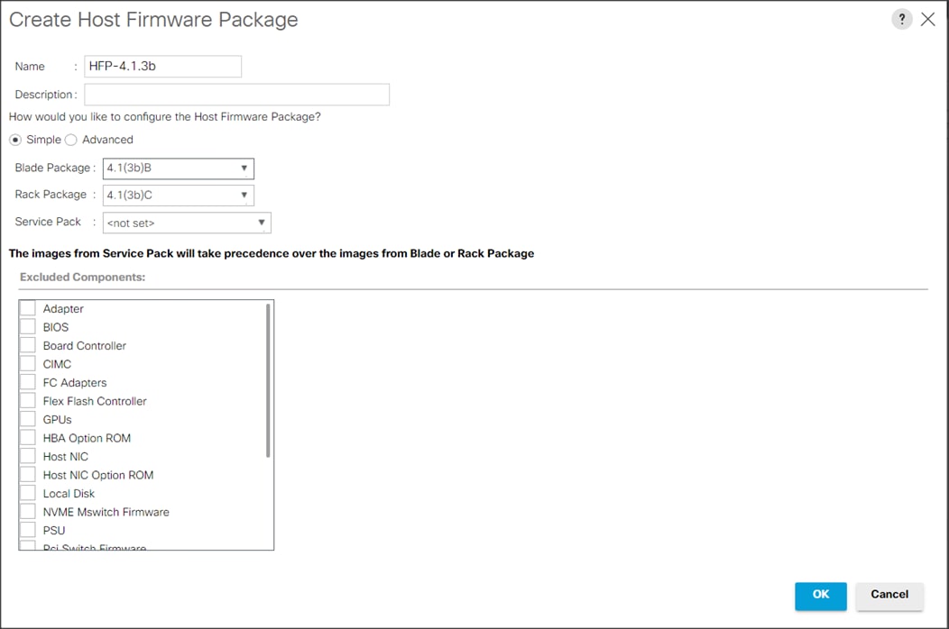
To create a power control policy for the Cisco UCS environment, follow these steps:
1. In Cisco UCS Manager, click the Servers tab in the navigation pane.
2. Select Policies > root > Sub-Organization > CDIP-CDP> Power Control Policies.
3. Right-click Power Control Policies.
4. Select Create Power Control Policy.
5. Select Fan Speed Policy as Max Power.
6. Enter NoPowerCap as the power control policy name.
7. Change the power capping setting to No Cap.
8. Click OK to create the power control policy.
Figure 45. Create Power Control Policy
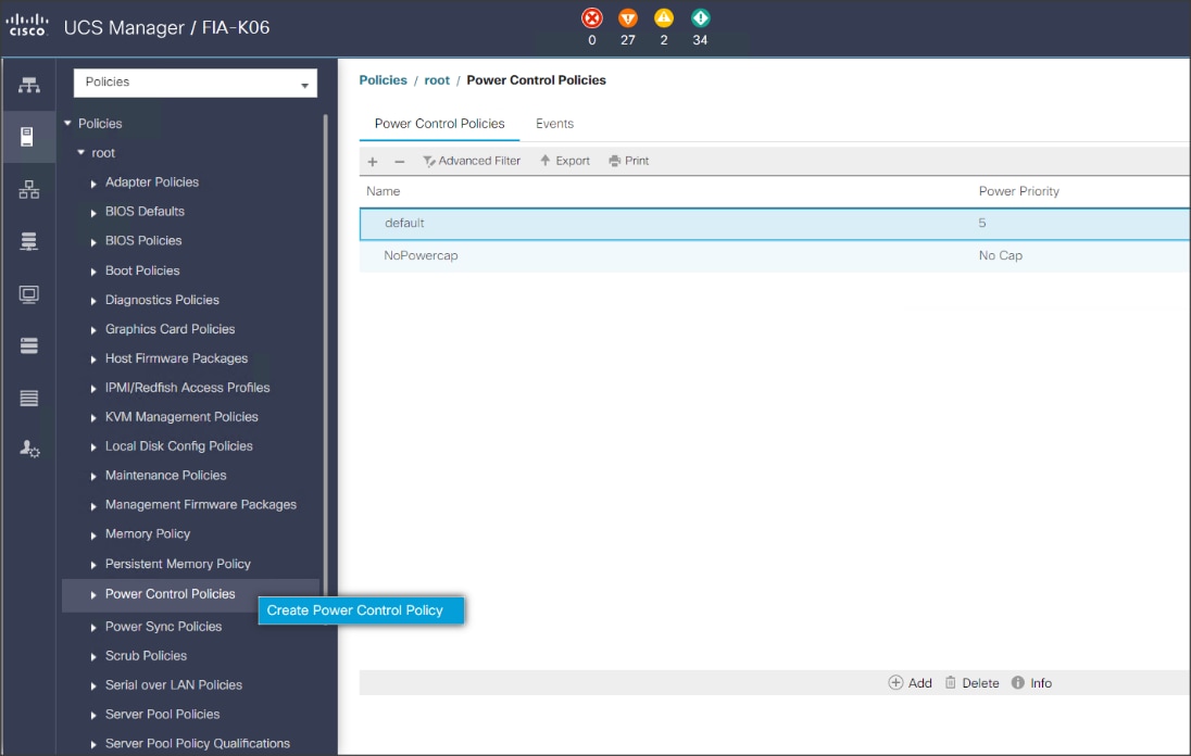
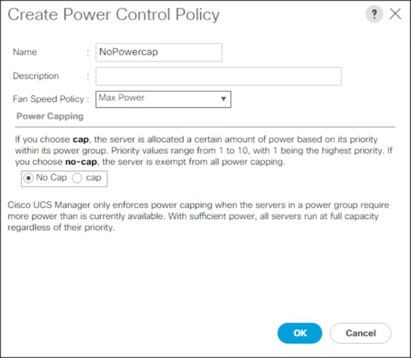
To create a server BIOS policy for the Cisco UCS environment, follow these steps:
1. In Cisco UCS Manager, click the Servers tab in the navigation pane.
2. Select Policies > root > Sub-Organization > CDIP-CDP> BIOS Policies.
3. Right-click BIOS Policies.
4. Select Create BIOS Policy.
5. Enter the BIOS policy name.
Figure 46. BIOS Configuration
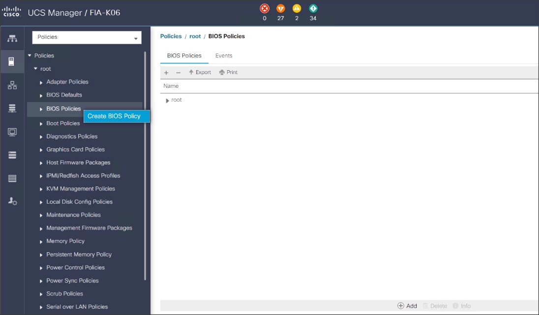
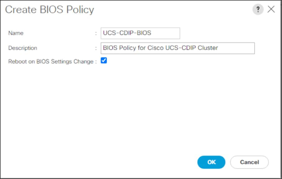
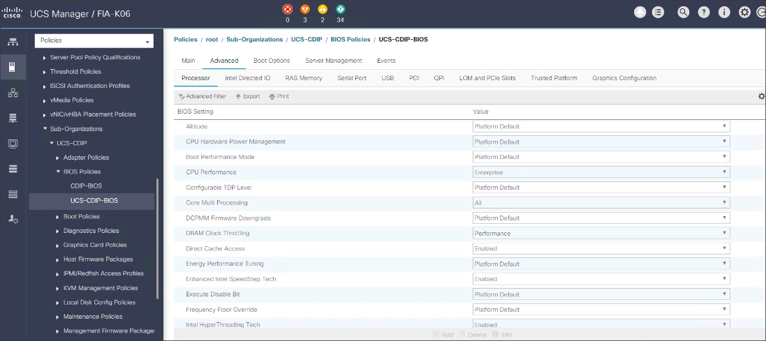
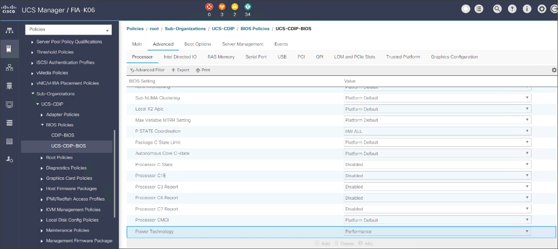
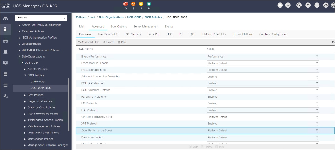
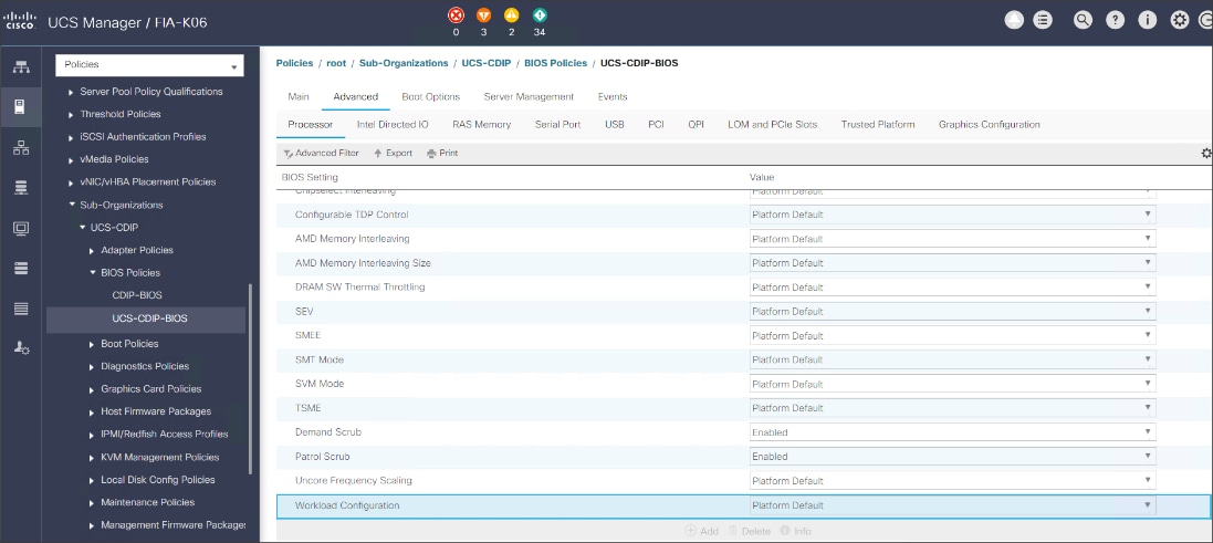
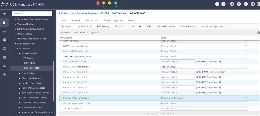
![]() For more information, go to: Performance Tuning Guide.
For more information, go to: Performance Tuning Guide.
![]() BIOS settings can have a significant performance impact, depending on the workload and the applications. The BIOS settings listed in this section is for configurations optimized for best performance which can be adjusted based on the application, performance, and energy efficiency requirements.
BIOS settings can have a significant performance impact, depending on the workload and the applications. The BIOS settings listed in this section is for configurations optimized for best performance which can be adjusted based on the application, performance, and energy efficiency requirements.
To update the default Maintenance Policy, follow these steps:
1. In Cisco UCS Manager, click the Servers tab in the navigation pane.
2. Select Policies > root > Sub-Organization > CDIP-CDP> Maintenance Policies.
3. Right-click Maintenance Policies to create a new policy.
4. Enter name for Maintenance Policy.
5. Change the Reboot Policy to User Ack.
6. Click Save Changes.
7. Click OK to accept the change.
Figure 47. Create Server Maintenance Policy
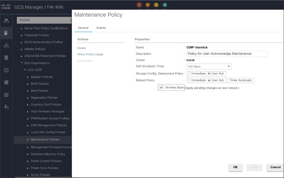
Create the Local Disk Configuration Policy
To create local disk configuration in the Cisco UCS Manager GUI, follow these steps:
1. Select the Servers tab in the Cisco UCS Manager GUI.
2. Select Policies > root > Sub-Organization > CDIP-CDP> Local Disk Config Policies.
3. Right-click Local Disk Config Policies and Select Create Local Disk Config Policies.
4. Enter UCS-Boot as the local disk configuration policy name.
5. Change the Mode to Any Configuration. Check the Protect Configuration box.
6. Keep the FlexFlash State field as default (Disable).
7. Keep the FlexFlash RAID Reporting State field as default (Disable).
8. Click OK to complete the creation of the Local Disk Configuration Policy.
9. Click OK.
Figure 48. Create the Local Disk Configuration Policy
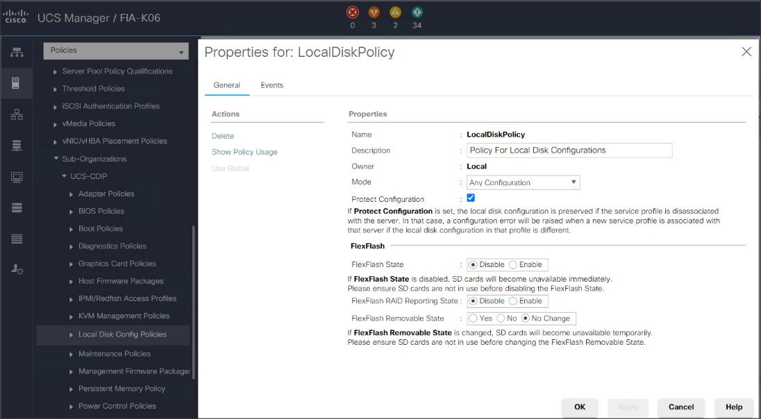
To create boot policies within the Cisco UCS Manager GUI, follow these steps:
1. Select the Servers tab in the Cisco UCS Manager GUI.
2. Select Policies > root.
3. Right-click the Boot Policies.
4. Select Create Boot Policy.
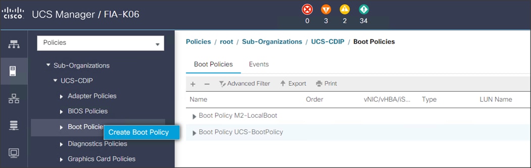
5. Enter ucs for the boot policy name.
6. (Optional) enter a description for the boot policy.
7. Keep the Reboot on Boot Order Change check box unchecked.
8. Keep Enforce vNIC/vHBA/iSCSI Name check box checked.
9. Keep Boot Mode Default (Legacy).
10. Expand Local Devices > Add CD/DVD and select Add Local CD/DVD.
11. Expand Local Devices and select Add Local Disk.
12. Expand vNICs and select Add LAN Boot and enter eth0.
13. Click OK to add the Boot Policy.
14. Click OK.
Figure 49. Create Boot Policy for Cisco UCS Server(s)
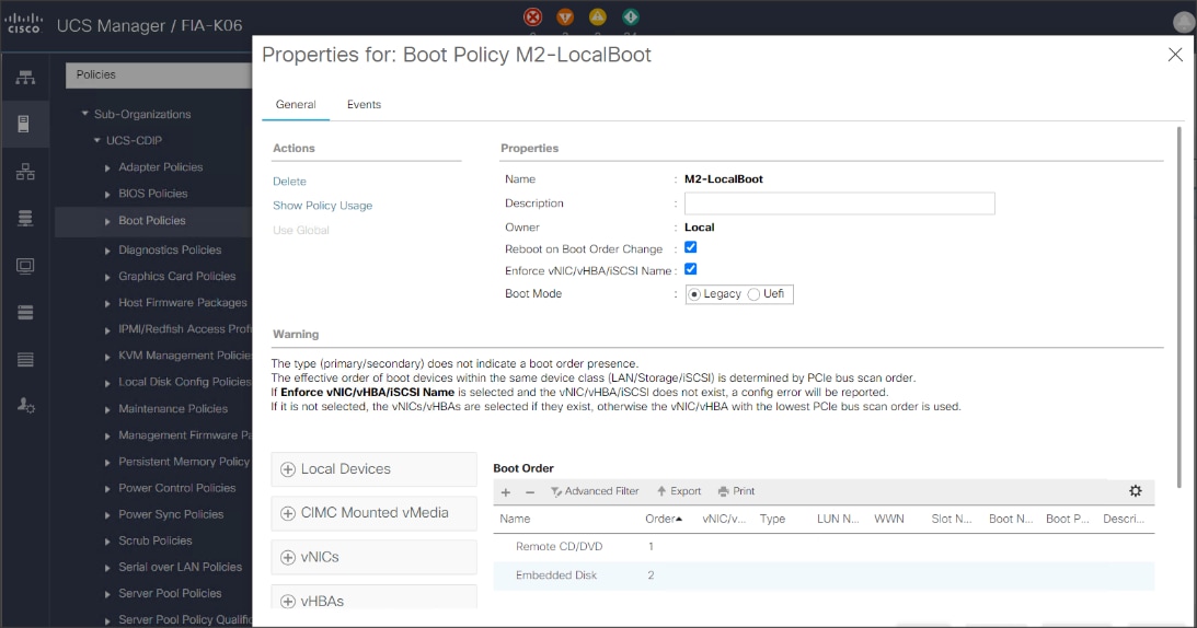
Create Storage Profile for Individual RAID0
To create the storage profile for the individual RAIDP, follow these steps:
1. On the UCSM navigation page, select the Storage tab.
2. From the Storage Profiles drop-down list, right-click and select Create Storage Profile.
Figure 50. Create Storage Profile
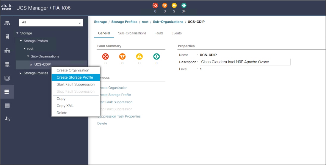
3. Enter a name for the Storage Profile and click the LUN Set tab.
4. Click Add.
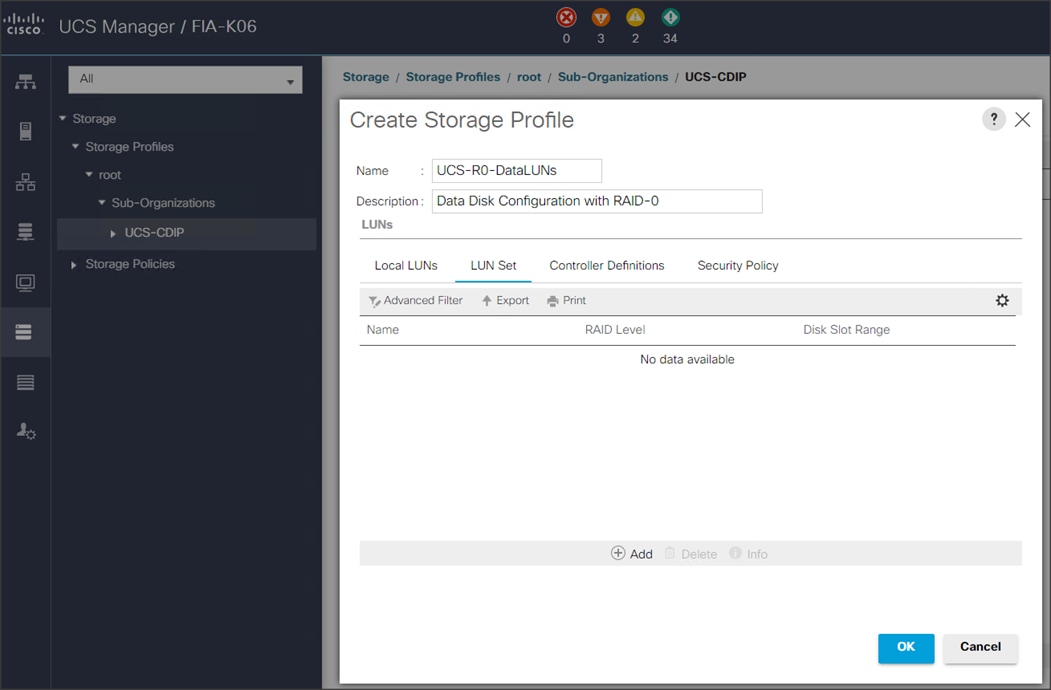
![]() The LUN Set policy configures all disks managed through Cisco UCS 240M5 Dual Raid Controller on 240M5 and Cisco 12G Modular Raid controller to individual disk RAID0.
The LUN Set policy configures all disks managed through Cisco UCS 240M5 Dual Raid Controller on 240M5 and Cisco 12G Modular Raid controller to individual disk RAID0.
5. Select the properties for the LUN set for HDD drives:
a. Enter a name for LUN set.
b. Disk Slot Range – 1 – 24/26/56 (Depends on number of drives installed in a server).
c. Enter Virtual Drive configuration:
§ Strip Size(kb) – 1024KB
§ Access Policy – Read Write
§ Read Policy – Read Ahead
§ Write Cache Policy – Write Back Good Bbu
§ IO Policy – Direct
§ Drive Cache – Disable
6. Select the properties for the LUN set for SDD drives:
a. Enter a name for LUN set.
◦ Disk Slot Range – 1 – 24/26/56 (Depends on number of drives installed in a server).
◦ Enter Virtual Drive configuration:
§ Strip Size(kb) – 1024KB
§ Access Policy – Read Write
§ Read Policy – Normal
§ Write Cache Policy – Write Through
§ IO Policy – Direct
§ Drive Cache – Platform Default
![]() For a LUN set based configuration, set the JBOD disks to unconfigured by selecting all JBOD disk in Server > Inventory > Disks, right-click and select Set JBOD to Unconfigured Good.
For a LUN set based configuration, set the JBOD disks to unconfigured by selecting all JBOD disk in Server > Inventory > Disks, right-click and select Set JBOD to Unconfigured Good.
Figure 51. Set JBOD Disks to Unconfigured Good
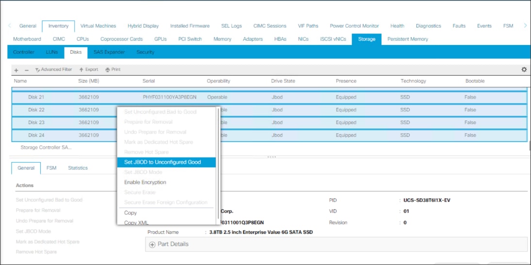
Create Storage Policy and Storage Profile
To create a Storage Profile with multiple RAID LUNs, create Storage Policies and attach them to a Storage Profile.
Configure Disk Group Policy for Cisco Boot Optimized M.2 RAID controller
To configure the disk group policy, follow these steps:
1. In the UCSM WebUI, Go to storage tab. In the Storage Policy section, right-click Disk Group Policies. Click Create Disk Group Policy.
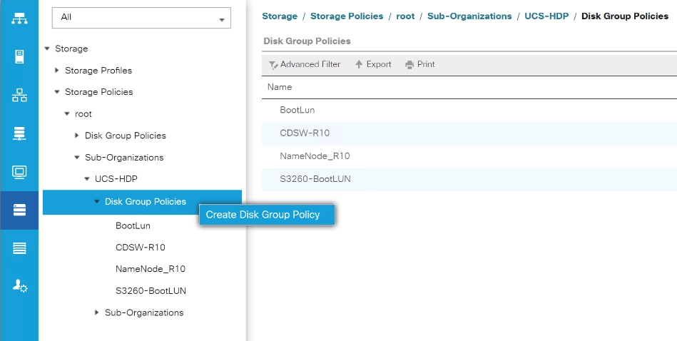
2. Enter a name and description for the new Disk Group Policy. Select Manual Disk Group Configuration. Click Add.
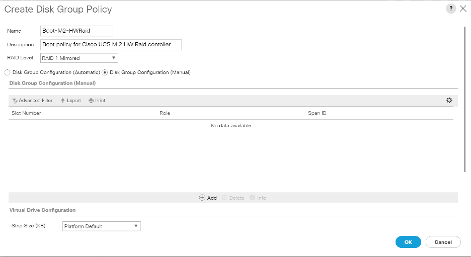
![]() M.2 disks are allocated Disk slot Number 253 and 254.
M.2 disks are allocated Disk slot Number 253 and 254.
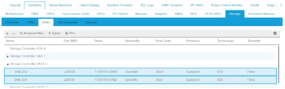
3. Enter Slot Number 253 for the first disk. Click OK.
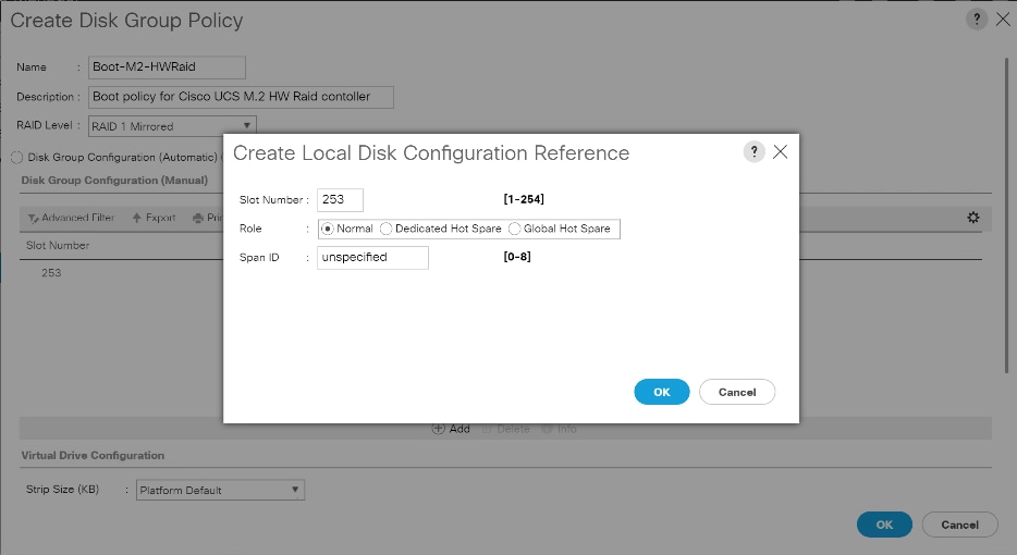
4. Click Add to add second disk, enter Slot Number 254.
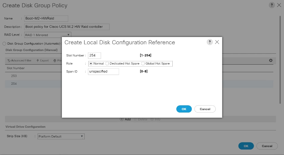
5. In Virtual Drive Configuration section leave all option as Platform Default. Click OK.
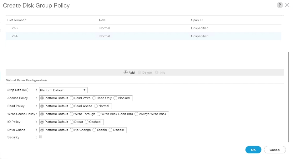
To configure the storage profile, follow these steps:
1. In the Storage Profiles section, select Storage Profiles. Right-click and select Create Storage Profile.
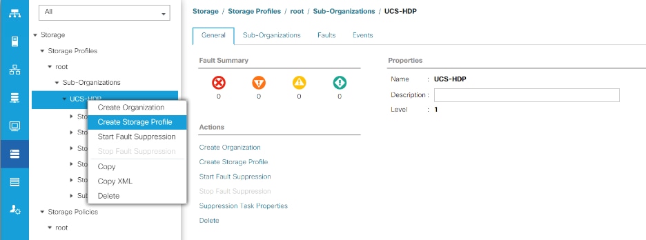
2. Enter a name for the Storage Profile. Click Add.
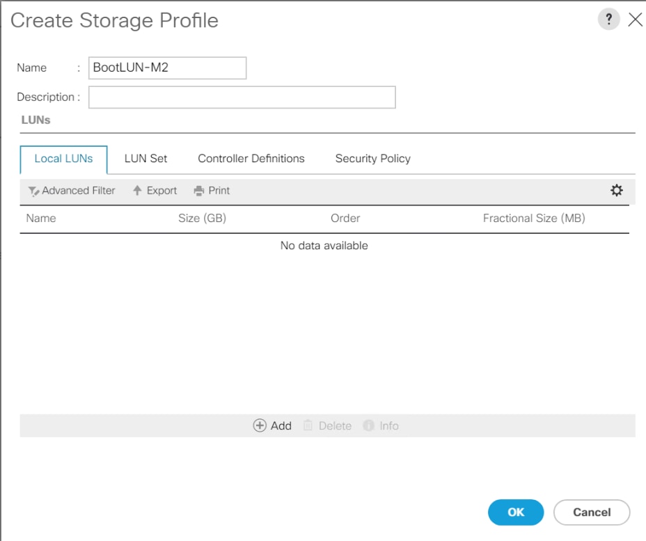
3. Enter a name for the Local LUN to be created, click Auto Deploy, check the box for Expand to Available, and from the drop-down list for Disk Group Configuration, select RAID 1 Disk Group Policy created for M.2 SATA Disks. Click OK.
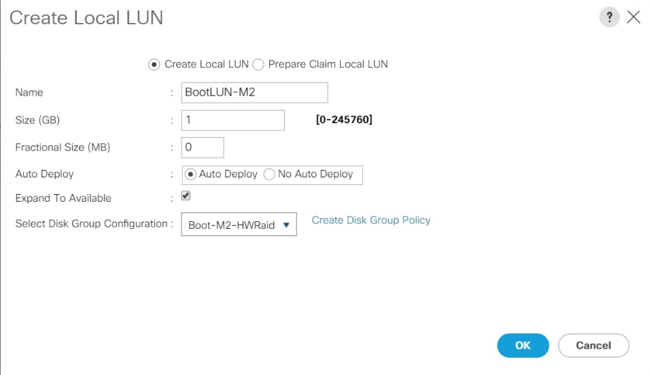
4. Attach a Storage Profile created to a Service profile or create a new Service Profile.
5. Go to the Storage tab on the Service Profile, select Storage Profile. Select Modify Storage Profile. Select Storage Profile created for M.2 SATA Disks.
Figure 52. Example of the Service Profile Associated to a Cisco UCS C240 M5 Server with Cisco UCS-M2-HWRAID and 2 240GB M.2 SATA SSD Installed
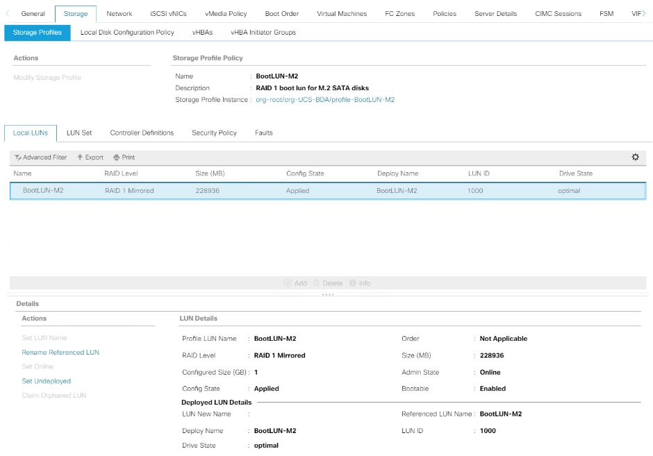
Figure 53. Example of Virtual Drive Created from 2 M.2 SATA SSD
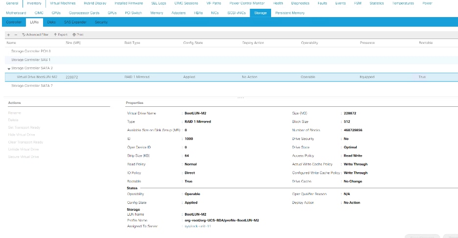
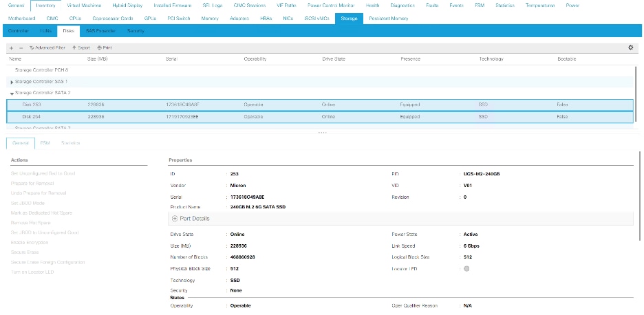
6. Go to the Storage tab on the left side panel selection, select Storage Policies.
7. From the Storage Policies drop-down list, select and right-click Disk Group Policies. Select Create Disk Group Policy.
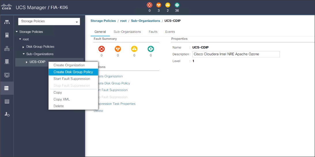
8. Enter name for Disk Group Policy, Select RAID level.
9. Select Disk Group Configuration (Automatic/Manual).
10. Disk Group Configuration.
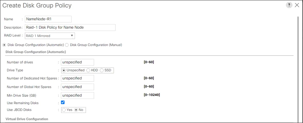
Virtual Drive Configuration.
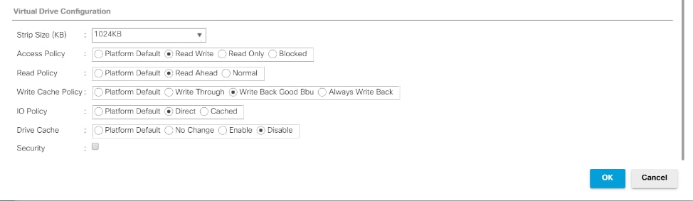
11. Select Storage Profiles, right-click and select Create Storage Profile.
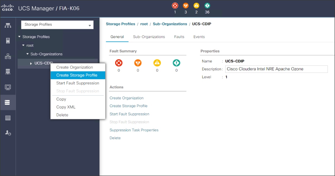
12. Enter a name for the Storage profile and click Add.
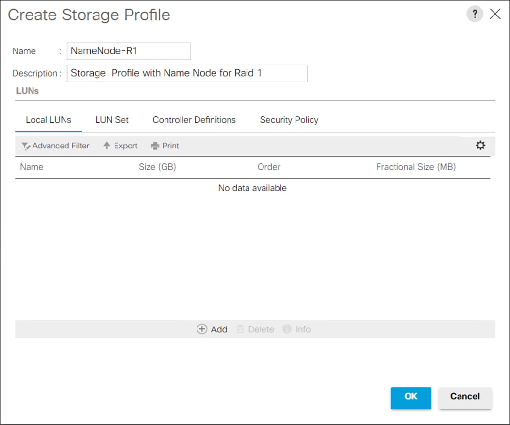
13. Enter a Local LUN name and select Auto Deploy.
14. Check the box for Expand to Available and from the drop-down list select the storage policy you want to attach with the Storage Profile. Click OK.
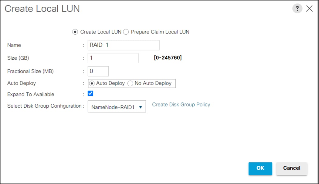
![]() For Cisco UCS 240M5, we created a Storage Profile with a Storage Policy to create a Boot LUN and attached it to a Storage Profile as shown above. The LUN set policy for an individual server node (server node 1 and server node 2) to create an individual RAID0.
For Cisco UCS 240M5, we created a Storage Profile with a Storage Policy to create a Boot LUN and attached it to a Storage Profile as shown above. The LUN set policy for an individual server node (server node 1 and server node 2) to create an individual RAID0.
Table 6. Storage Configuration
| Disk Slot (RAID configuration) |
Disk Type and Assigned Role (Node type) |
| Slot 253-254 (Raid 1) |
M.2 SATA SSD for OS boot (Apache Ozone Master and Data Node) |
| Slot 1-2 (Raid 1) |
NVMe Disks for Apache Ozone Metadata boot (Apache Ozone Master and Data Node) |
| Slot 3-12 (Raid 1) |
SSD/HDD Disks (Apache Ozone Master Node) |
| Slot 3-26 (JBOD/Raid 0) |
SSD/ HDD Data Disks (Apache Ozone Data Node) |
![]() For HDD drives its recommended to build Raid 0 with virtual drive properties set as highlighted in the Disk group policy creation. SSD drives recommended to set as JBOD. On Cisco UCS C240 M5SX Rack Server two NVMe can be installed in slot 1-2 and/or Rear slot 25-26 for metadata Disks which requires Riser 2B or Riser 2C based on Front and/or Rear NVMe connection and are managed by CPU 2. There is no RAID controller support for NVMe drives.
For HDD drives its recommended to build Raid 0 with virtual drive properties set as highlighted in the Disk group policy creation. SSD drives recommended to set as JBOD. On Cisco UCS C240 M5SX Rack Server two NVMe can be installed in slot 1-2 and/or Rear slot 25-26 for metadata Disks which requires Riser 2B or Riser 2C based on Front and/or Rear NVMe connection and are managed by CPU 2. There is no RAID controller support for NVMe drives.
Create Service Profile Template
To create a service profile template, follow these steps:
1. In the Cisco UCS Manager, go to Servers > Service Profile Templates > root Sub Organization > CDIP-CDP> and right-click Create Service Profile Template as shown below.
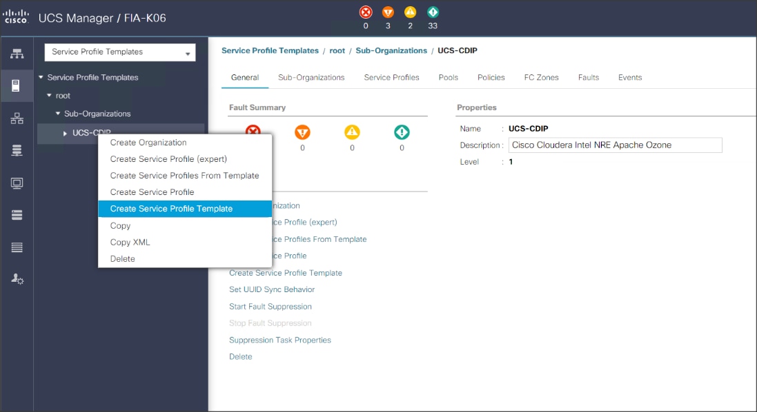
2. Enter the Service Profile Template name, Updating Template as type of template and select the UUID Pool that was created earlier. Click Next.
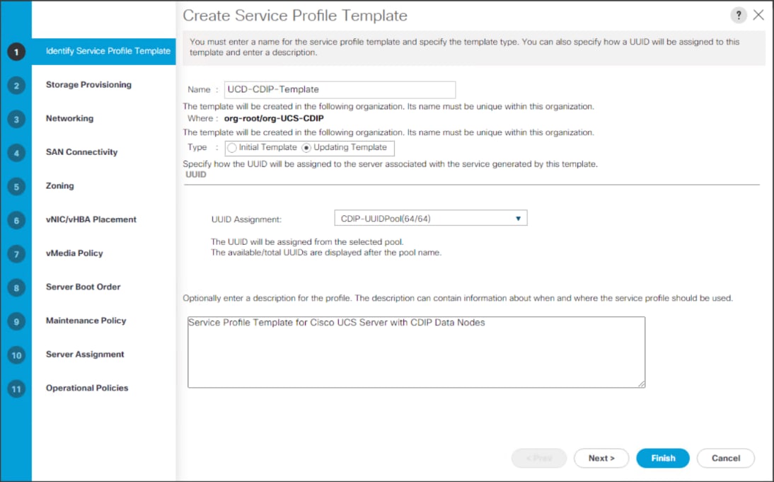
3. On Storage Profile Policy, select the Storage Profile to attach with the server.
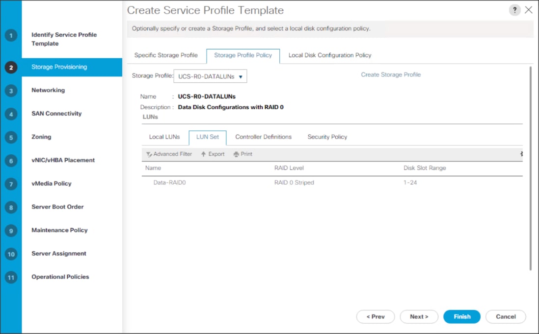
![]() Based on the server model or the role of the server, we created and attached a Storage Profile for NameNode(s), DataNode(s) and Cisco UCS 240M5 Storage server in different Service Profile Template for each.
Based on the server model or the role of the server, we created and attached a Storage Profile for NameNode(s), DataNode(s) and Cisco UCS 240M5 Storage server in different Service Profile Template for each.
4. In the networking window, select Expert and click Add to create vNICs. Add one or more vNICs that the server should use to connect to the LAN.
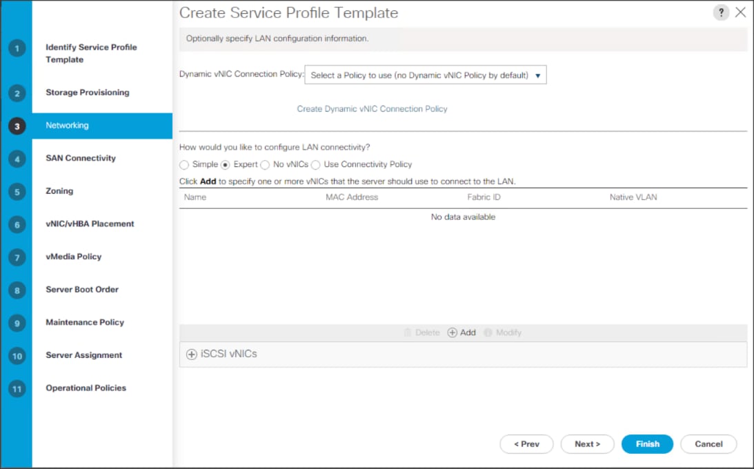
5. In the create vNIC menu as vNIC name.
6. Select vNIC Template as vNIC0 and Adapter Policy as Linux.
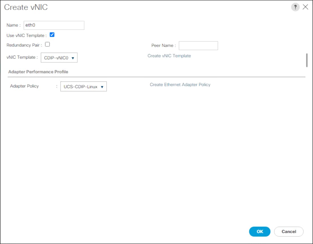

![]() Optionally, Network Bonding can be setup on the vNICs for each host for redundancy as well as for increased throughput.
Optionally, Network Bonding can be setup on the vNICs for each host for redundancy as well as for increased throughput.
7. In the SAN Connectivity menu, select no vHBAs.
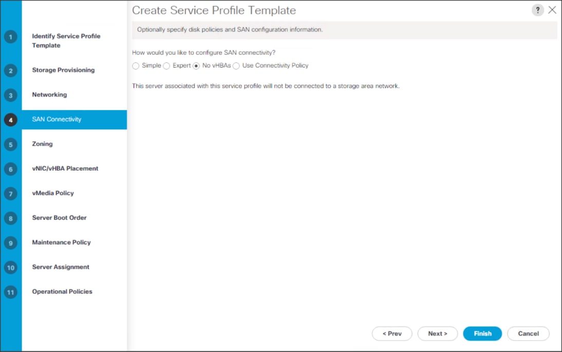
8. Click Next in the Zoning tab.
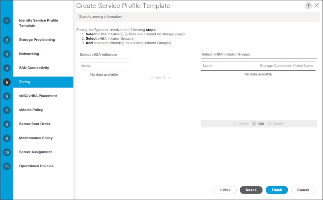
9. Select Let System Perform Placement for vNIC/vHBA Placement. Click Next.
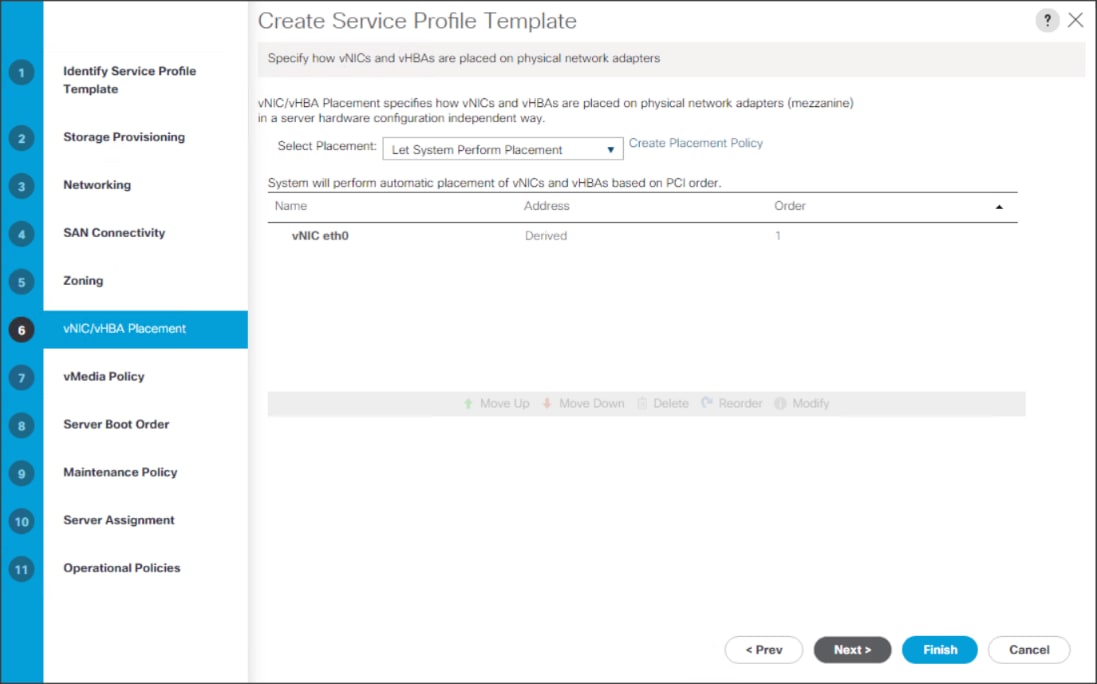
10. Click Next in the vMedia Policy tab.
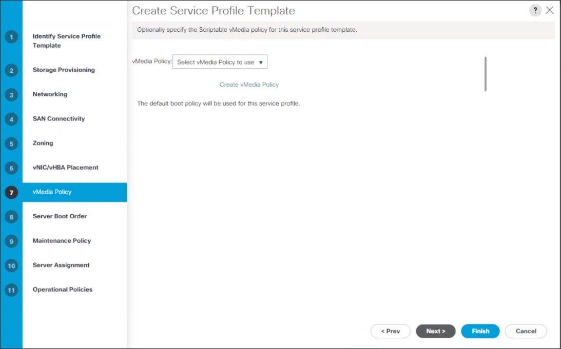
11. Select Boot Policy in the Server Boot Order tab.
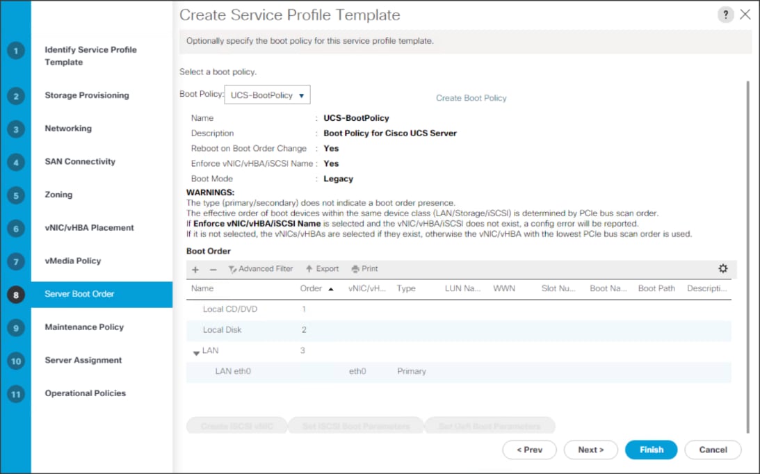
12. Select UserAck maintenance policy, which requires user acknowledgement prior rebooting server when making changes to policy or pool configuration tied to a service profile.
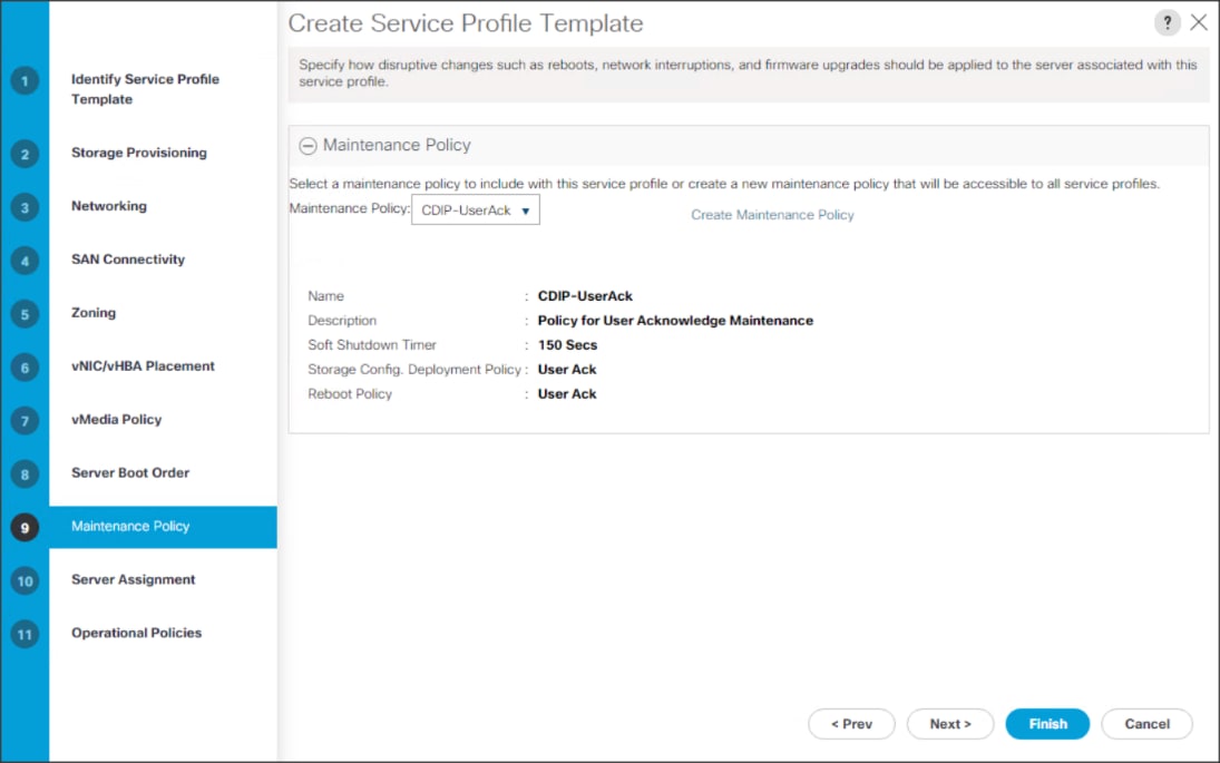
13. Select the Server Pool policy to automatically assign a service profile to a server that meets the requirements for server qualification based on the pool configuration. Select Power state when the Service Profile is associated to server
14. On the same page you can configure Host firmware Package Policy which helps to keep the firmware in sync when associated to server.
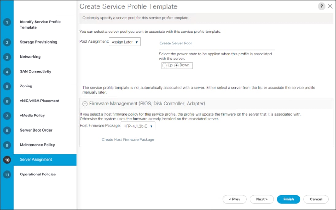
![]() On the Operational Policy page, we configured the BIOS policy for a Cisco UCS C240 M5 Rack server with the Power Control Policy set to NoPowerCap for maximum performance.
On the Operational Policy page, we configured the BIOS policy for a Cisco UCS C240 M5 Rack server with the Power Control Policy set to NoPowerCap for maximum performance.
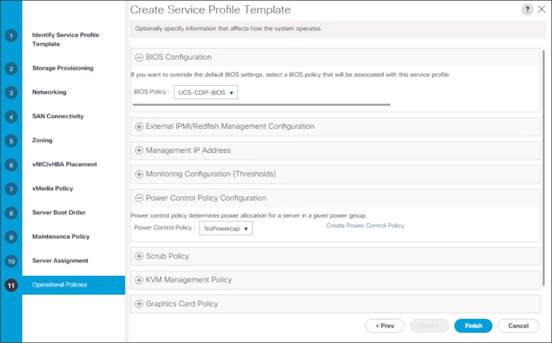
15. Click Finish to create the Service Profile template.
Create Service Profiles from Template
To create a Service Profile from a template, follow these steps:
1. Right-click the Service Profile Template and select Create Service profile from Template.
Figure 54. Create Service Profile from Template
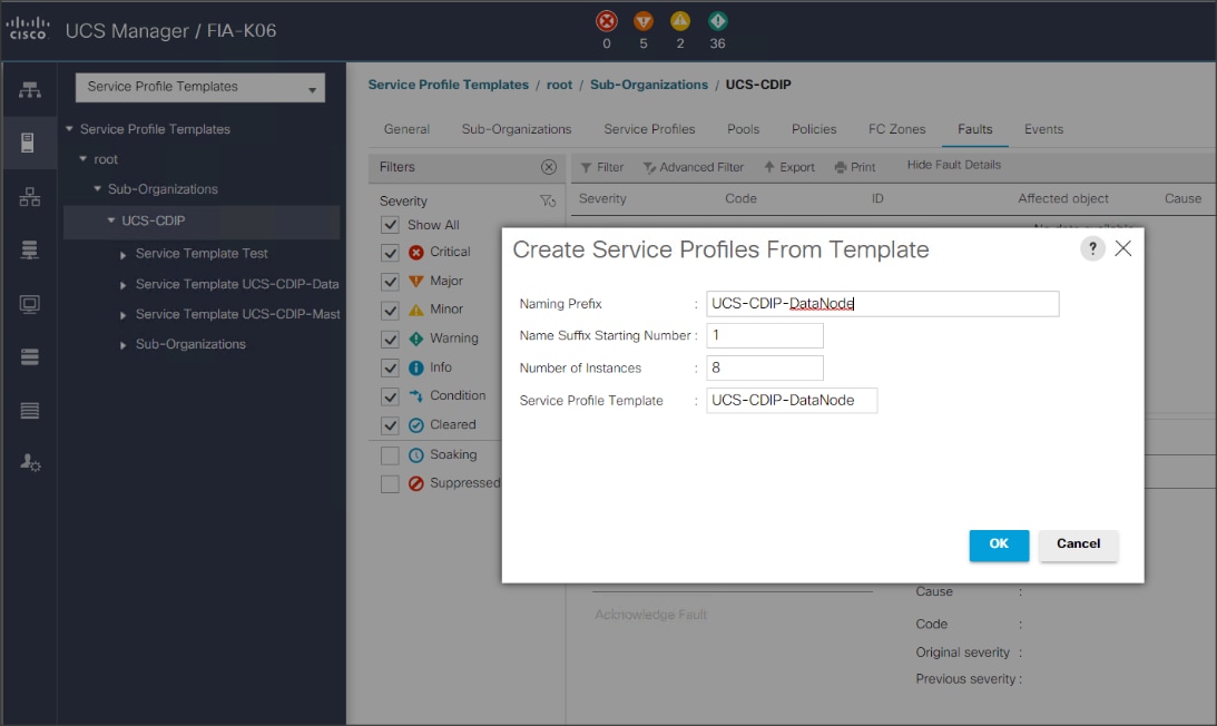
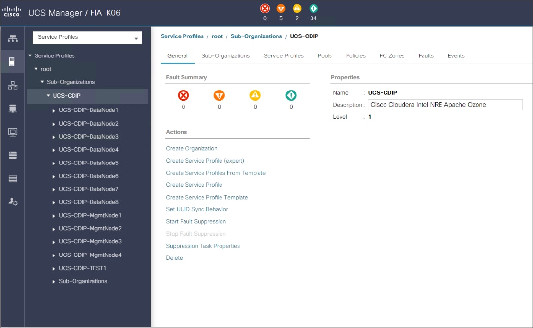
![]() The Service profile will automatically assign to servers discovered and meets the requirement of Server Pool.
The Service profile will automatically assign to servers discovered and meets the requirement of Server Pool.
2. Repeat this step to create service profile template(s) and service profile(s) according to different deployment scenario.
Configure RAID 1 on PCIe NVMe Drives using Intel Volume Management Device
![]() This requires that BIOS Boot Mode option be set to UEFI and Enable VMD Enable BIOS token. For detailed information on enabling Intel® Volume Management Device refer to: https://www.cisco.com/c/en/us/td/docs/unified_computing/ucs/ucs-manager/GUI-User-Guides/Storage-Mgmt/4-1/b_UCSM_GUI_Storage_Management_Guide_4_1/b_UCSM_GUI_Storage_Management_Guide_4_1_chapter_01001.html#id_123876
This requires that BIOS Boot Mode option be set to UEFI and Enable VMD Enable BIOS token. For detailed information on enabling Intel® Volume Management Device refer to: https://www.cisco.com/c/en/us/td/docs/unified_computing/ucs/ucs-manager/GUI-User-Guides/Storage-Mgmt/4-1/b_UCSM_GUI_Storage_Management_Guide_4_1/b_UCSM_GUI_Storage_Management_Guide_4_1_chapter_01001.html#id_123876
NVMe drives can be installed in slot 1-2 and/or slot 25-26 in Cisco UCS C240 M5 Rack Server. For more details: https://www.cisco.com/c/dam/en/us/products/collateral/servers-unified-computing/ucs-c-series-rack-servers/c240m5-sff-specsheet.pdf
To configure RAID 1 on PCIe NVMe drives, follow these steps:
1. To configure RAID 1 on NVMe drives the Intel® Volume Management Device (Intel® VMD) features must be enabled in BIOS.
Figure 55. Intel VMD BIOS Configuration
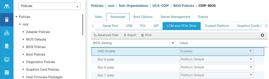
2. Boot server press F2 option when prompted to enter in to BIOS setup.
3. Go to Advance menu. Select Intel Virtual RAID on CPU. Press Enter.
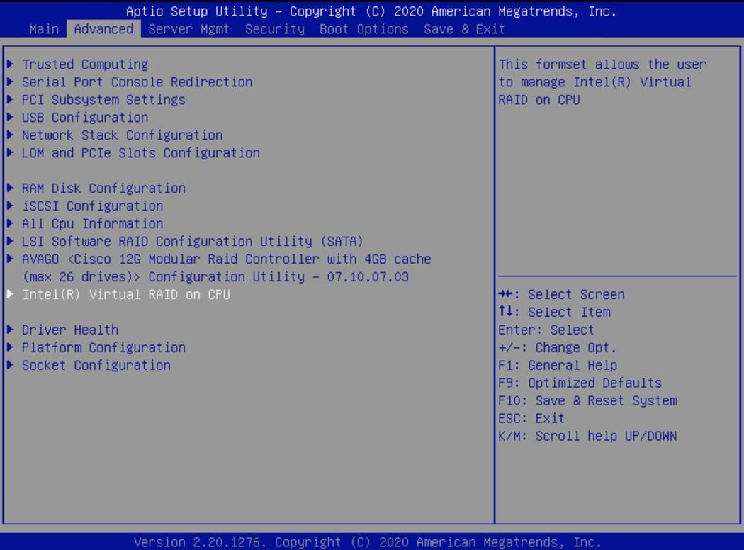
4. Select All Intel VMD Controllers. Press Enter.
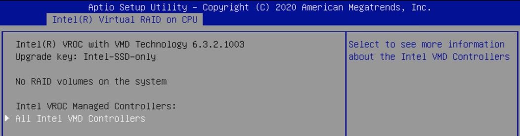
5. Select Create RAID Volume. Press Enter.
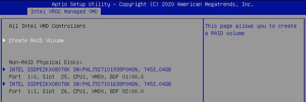
6. Enter or select properties under Create RAID Volume as shown below. Select Create Volume and press Enter:
● Name
● RAID Level
● Enable RAID spanned over VMD Controllers
● Select Disk(s)
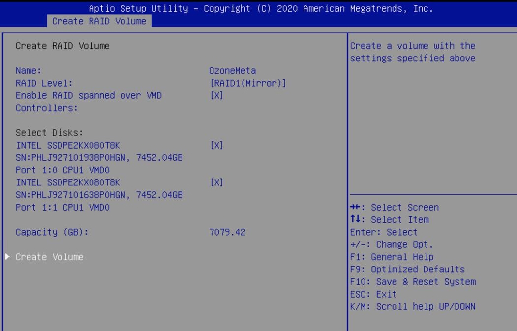
![]() We create RAID 1 from two Intel P4510 8TB NVMe installed in slot 25-26 in Cisco UCS C240 M5 Rack Server.
We create RAID 1 from two Intel P4510 8TB NVMe installed in slot 25-26 in Cisco UCS C240 M5 Rack Server.
7. Details of the RAID volume(s) created will be displayed under Intel VROC Managed VMD page.
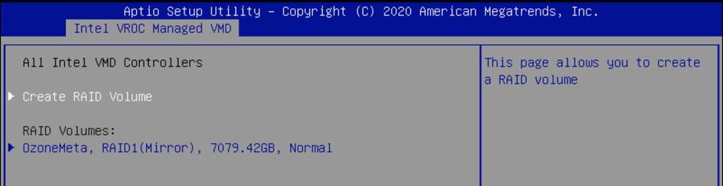
8. Press F10 to save and exit.
Install Red Hat Enterprise Linux 7.8
This section provides detailed procedures for installing Red Hat Enterprise Linux Server using Software RAID (OS based Mirroring) on Cisco UCS C240 M5 servers. There are multiple ways to install the RHEL operating system. The installation procedure described in this deployment guide uses KVM console and virtual media from Cisco UCS Manager.
![]() In this study, RHEL version 7.8 DVD/ISO was utilized for OS the installation on Cisco UCS C240 M5 Rack Servers.
In this study, RHEL version 7.8 DVD/ISO was utilized for OS the installation on Cisco UCS C240 M5 Rack Servers.
To install the Red Hat Enterprise Linux 7.8 operating system, follow these steps:
1. Log into the Cisco UCS Manager.
2. Select the Equipment tab.
3. In the navigation pane expand Rack-Mounts and then Servers.
4. Right-click the server and select KVM console.
5. In the right pane, click the KVM Console >>.
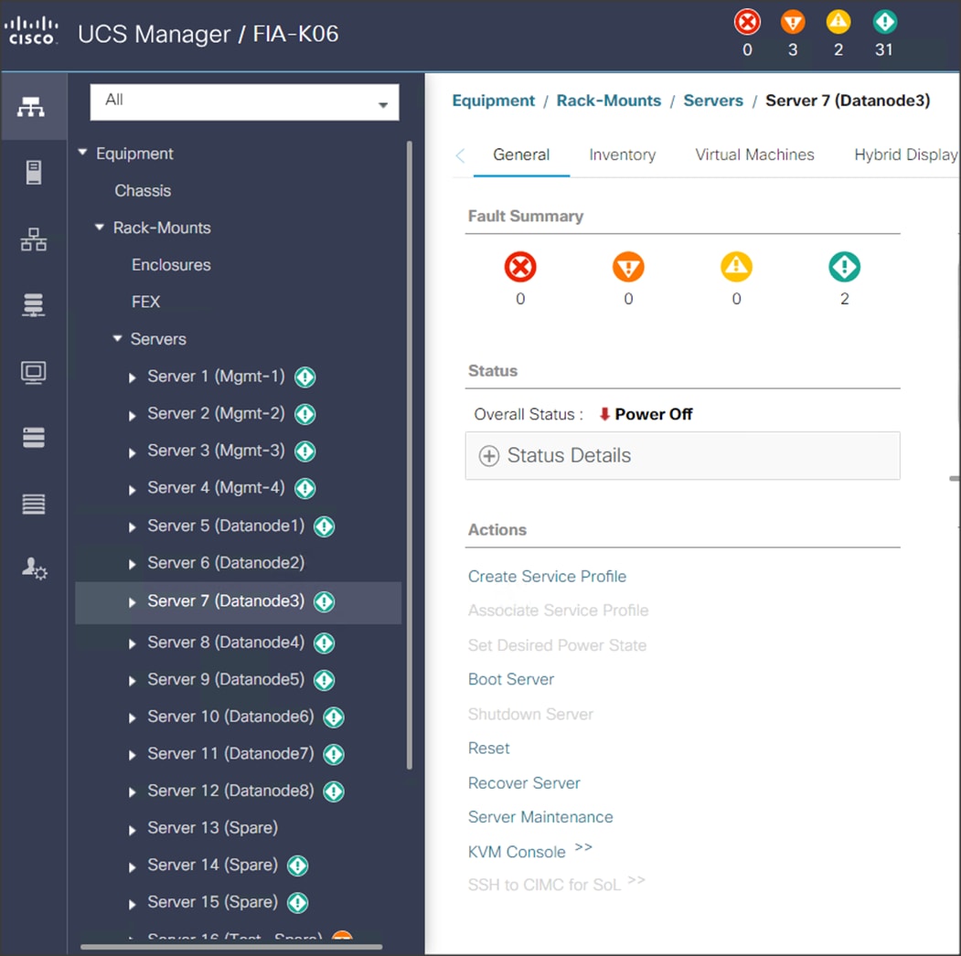
6. Click the link to launch the KVM console.
7. Point the cursor over the top right corner and select the Virtual Media tab.
8. Click the Activate Virtual Devices found in Virtual Media tab.

9. Click the Virtual Media tab to select CD/DVD.
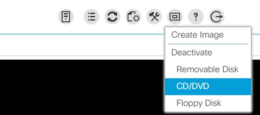
10. Select Map Drive in the Virtual Disk Management windows.
11. Browse to the Red Hat Enterprise Linux 7.8 installer ISO image file.
![]() The Red Hat Enterprise Linux 7.8 Server DVD is assumed to be on the client machine.
The Red Hat Enterprise Linux 7.8 Server DVD is assumed to be on the client machine.
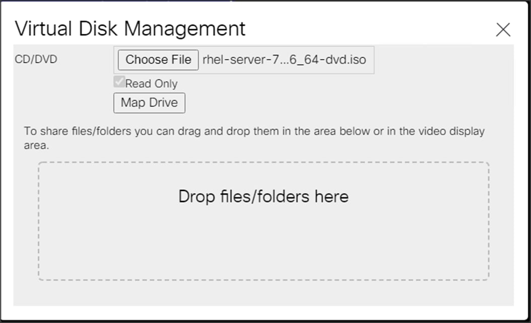
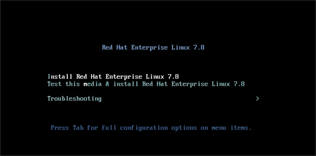
12. Click Open to add the image to the list of virtual media.
13. Select the Installation option from Red Hat Enterprise Linux 7.8
14. Select the language for the installation and click Continue.
15. Select date and time, which pops up another window as shown below.
16. Select the location on the map, set the time, and click Done.
17. Click Installation Destination.
18. This opens a new window with the boot disks. Make the selection and choose I will configure partitioning. Click Done. We selected ATA Cisco VD (RAID 1 virtual disk created via Storage profile from two M.2 Boot SATA SSDs).
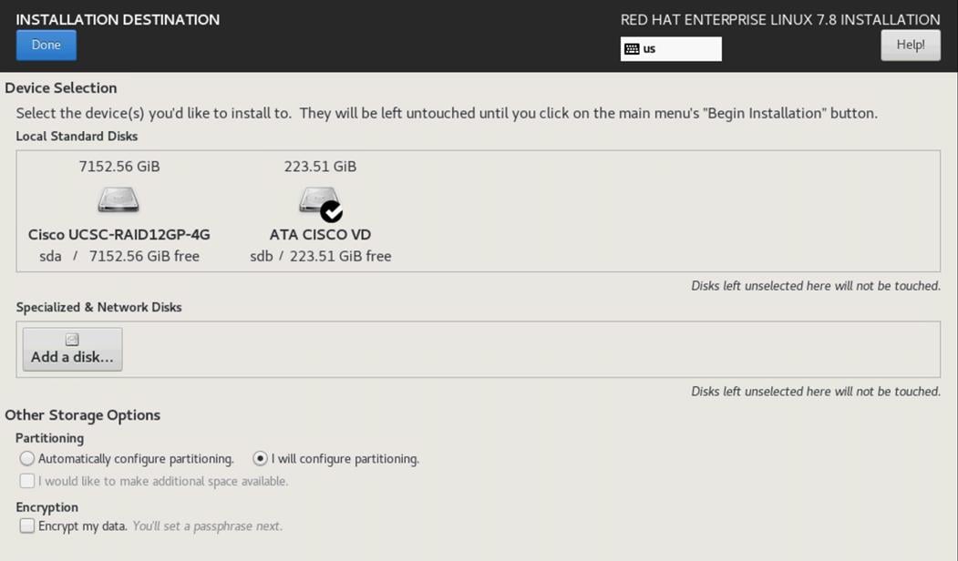
19. This opens a window to create the partitions. Click the + sign to add a new partition as shown below with a /boot/efi boot partition size 2048 MB. Click Add Mount Point to add the partition.
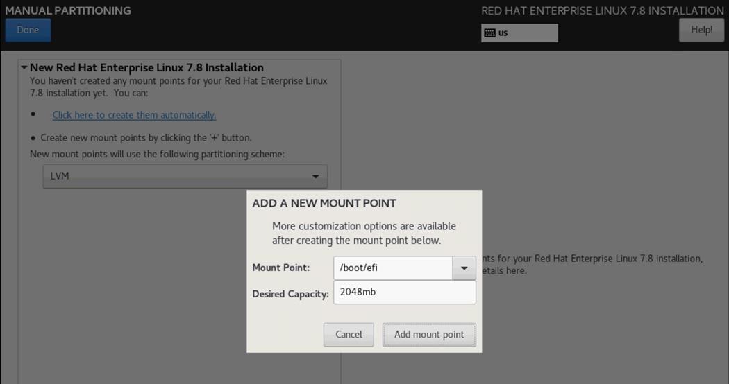
20. Click the + sign to create the /boot partition of size 2048 MB. Click Add Mount Point.
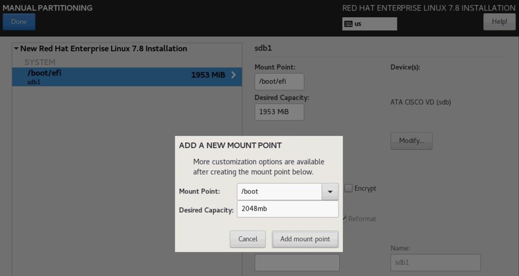
21. Click the + sign to create the swap partition of size 2048 MB. Click Add Mount Point.
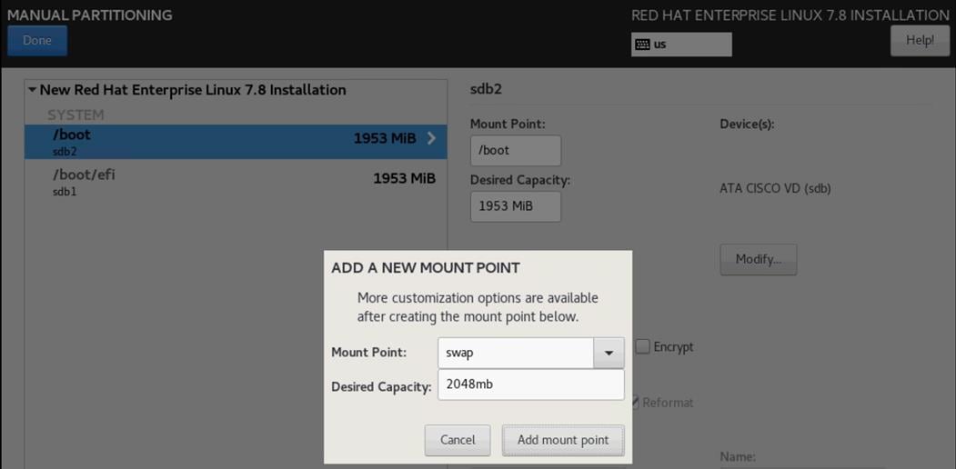
22. Click + to add the / partition. The size can be left empty so it will use the remaining capacity. Click Add Mountpoint.
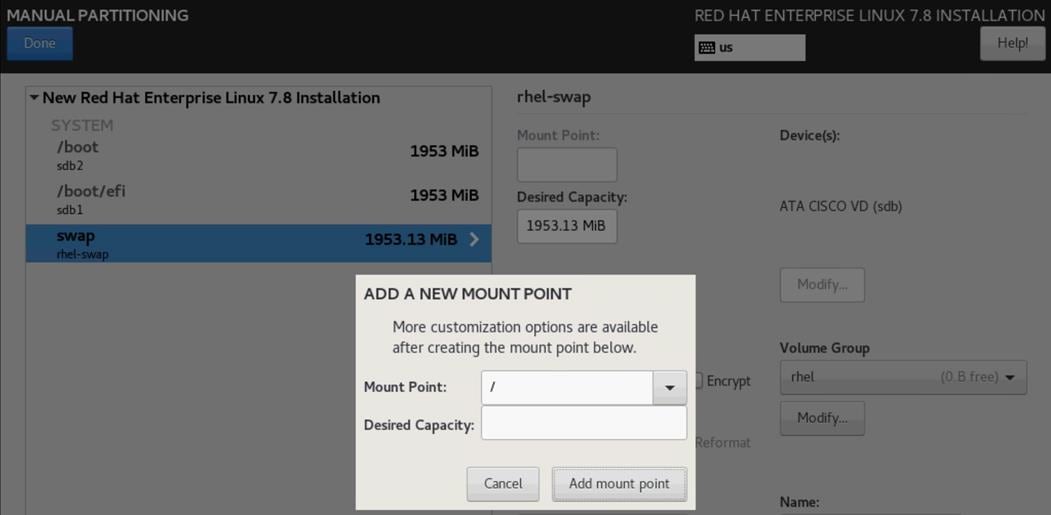
23. Click Done.
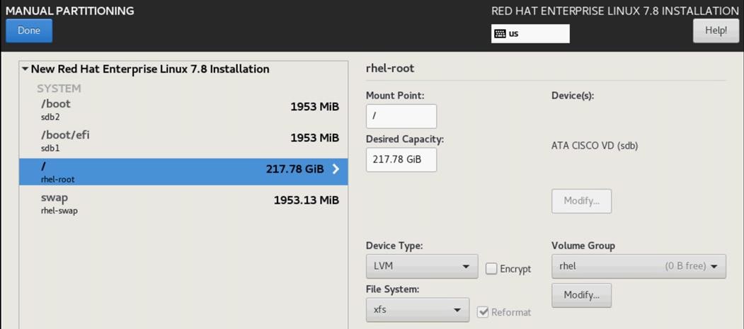
24. Accept Changes.
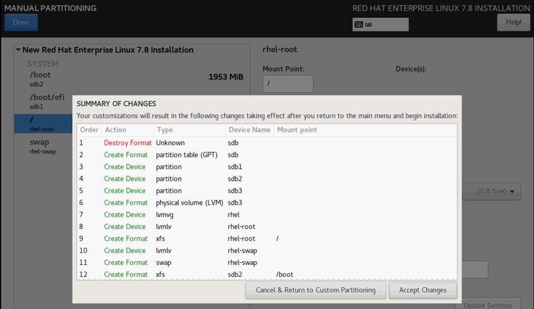
25. Click Software Selection.
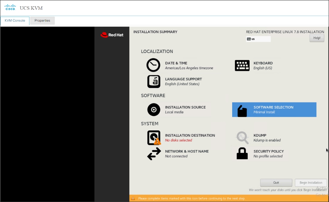
26. Select Infrastructure Server and select the Add-Ons as noted below, then click Done:
a. Network File System Client:
◦ Performance Tools
◦ Compatibility Libraries
◦ Development Tools
◦ Security Tools
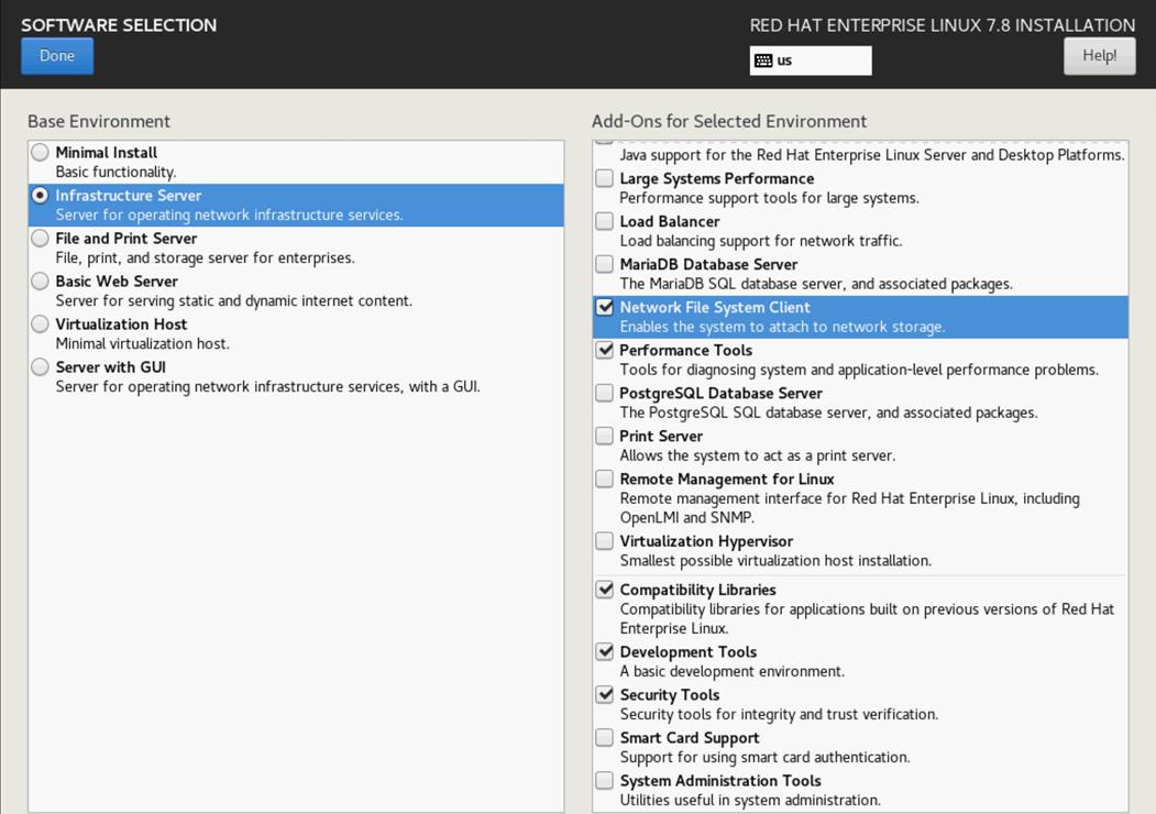
27. Click Network and Hostname and configure Hostname and Networking for the Host.
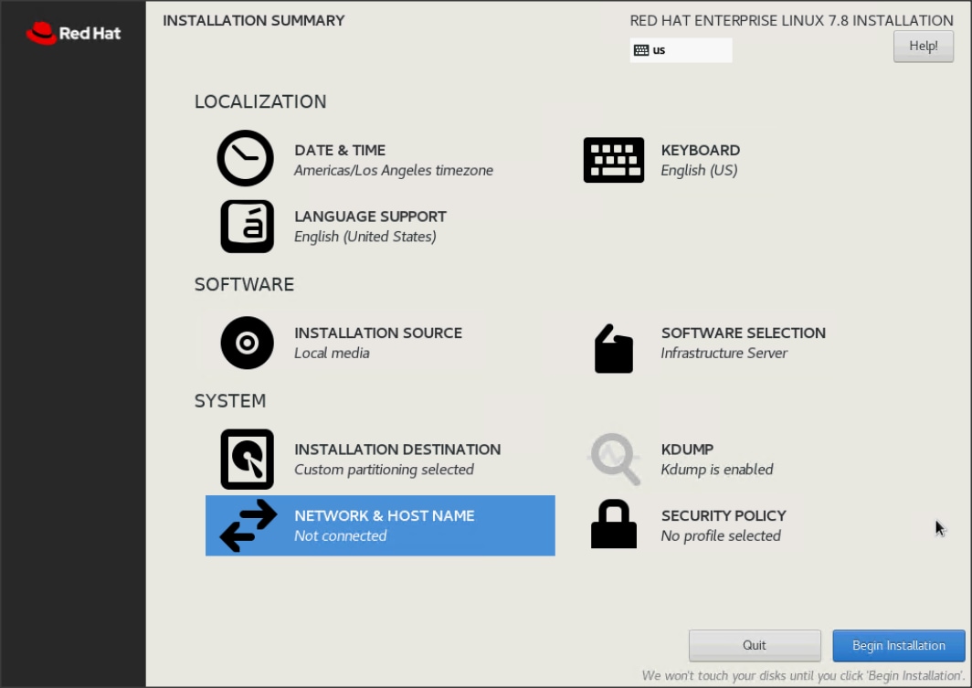
28. Type in the hostname as shown below.
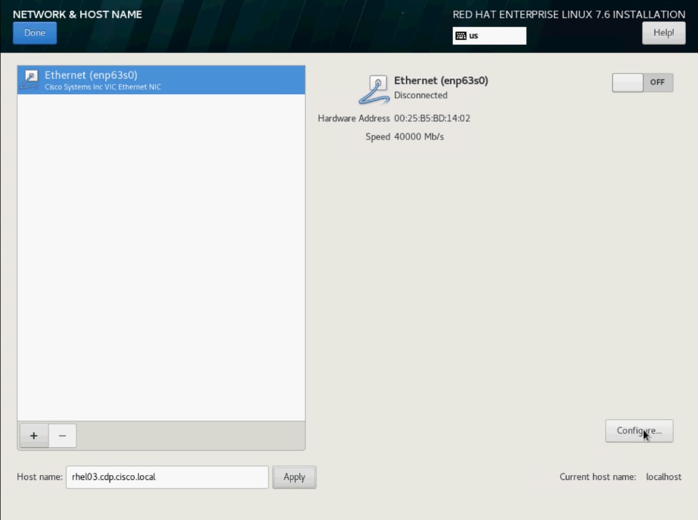
29. Click Configure to open the Network Connectivity window. Click IPv4 Settings.
30. Change the Method to Manual and click Add to enter the IP Address, Netmask and Gateway details.
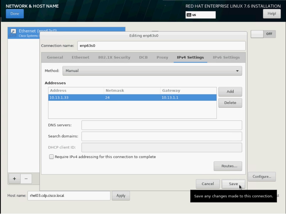
31. Click Save, update the hostname, and turn Ethernet ON. Click Done to return to the main menu.
32. Click Begin Installation in the main menu.
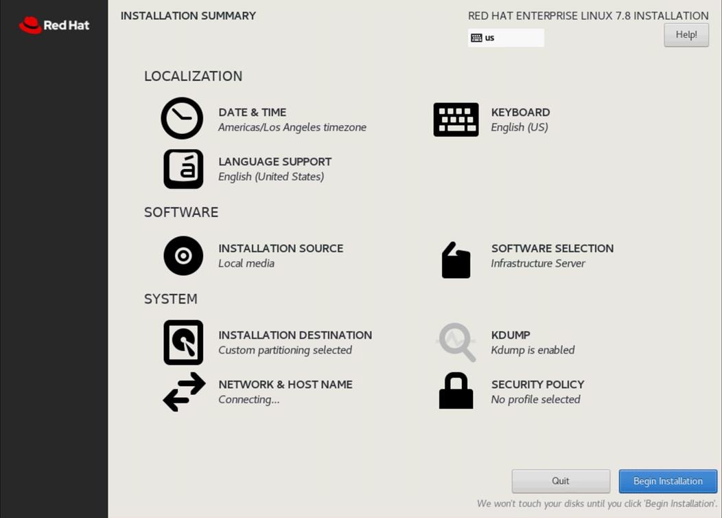
33. Select Root Password in the User Settings.
34. Enter the Root Password and click Done.
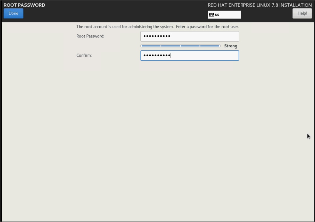
35. When the installation is complete, reboot the system.
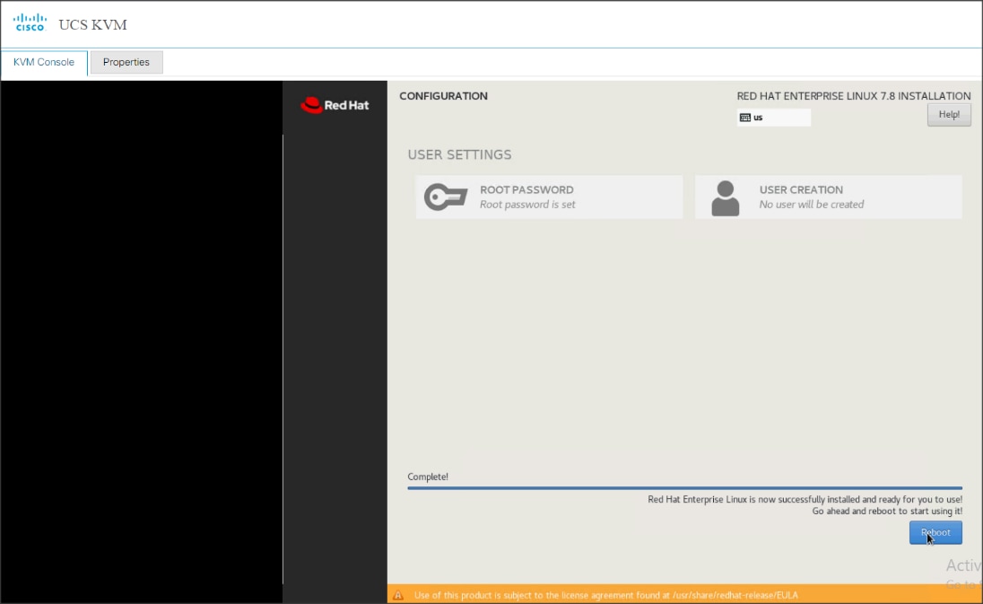
36. Repeat steps 1 to 36 to install Red Hat Enterprise Linux 7.8 on remaining servers.
![]() The OS installation and configuration of the nodes that is mentioned above can be automated through PXE boot or third-party tools.
The OS installation and configuration of the nodes that is mentioned above can be automated through PXE boot or third-party tools.
The hostnames and their corresponding IP addresses are shown in Table 7.
Table 7. Hostname and IP address
| Hostname |
Eth0 |
| rhelnn01 |
10.15.1.101 |
| ……… |
………… |
| rhelnn04 |
10.15.1.104 |
| rhel01 |
10.15.1.105 |
| rhel02 |
10.15.1.106 |
| ……… |
………… |
| Rhel07 |
10.15.1.111 |
| Rhel08 |
10.15.1.112 |
![]() Multi-homing configuration is not recommended in this design, so please assign only one network interface on each host.
Multi-homing configuration is not recommended in this design, so please assign only one network interface on each host.
![]() For simplicity, outbound NATing is configured for internet access when desired, such as accessing public repos and/or accessing Red Hat Content Delivery Network. However, configuring outbound NAT is beyond the scope of this document.
For simplicity, outbound NATing is configured for internet access when desired, such as accessing public repos and/or accessing Red Hat Content Delivery Network. However, configuring outbound NAT is beyond the scope of this document.
Choose one of the nodes of the cluster or a separate node as the Admin Node for management, such as CDP PvC Base installation, Ansible, creating a local Red Hat repo, and others. In this document, we used rhelnn01 for this purpose.
Setup /etc/hosts on the Admin node; this is a pre-configuration to setup DNS as shown in the next section.
![]() For the purpose of simplicity, /etc/hosts file is configured with hostnames in all the nodes. However, in large scale production grade deployment, DNS server setup is highly recommended. Furthermore, /etc/hosts file is not copied into containers running on the platform.
For the purpose of simplicity, /etc/hosts file is configured with hostnames in all the nodes. However, in large scale production grade deployment, DNS server setup is highly recommended. Furthermore, /etc/hosts file is not copied into containers running on the platform.
Below are the sample A records for DNS configuration within Linux environment:
ORIGIN cdpdc.cisco.local
rhel01 A 10.15.1.105
rhel02 A 10.15.1.106
rhel03 A 10.15.1.107
…
…
Rhel07 A 10.15.1.111
Rhel08 A 10.15.1.112
rhelnn01 A 10.15.1.101
rhelnn02 A 10.15.1.102
rhelnn03 A 10.15.1.103
rhelnn04 A 10.15.1.104
To create the host file on the admin node, follow these steps:
1. Log into the Admin Node (rhelnn01).
#ssh 10.15.1.101
2. Populate the host file with IP addresses and corresponding hostnames on the Admin node (rhelnn01) and other nodes as follows:
On Admin Node (rhelnn01):
[root@rhelnn01 ~]# cat /etc/hosts
127.0.0.1 localhost localhost.localdomain localhost4 localhost4.localdomain4
10.15.1.101 rhelnn01.cisco.local rhelnn01
10.15.1.102 rhelnn02.cisco.local rhelnn02
10.15.1.103 rhelnn03.cisco.local rhelnn03
10.15.1.104 rhelnn04.cisco.local rhelnn04
10.15.1.105 rhel01.cisco.local rhel01
10.15.1.106 rhel02.cisco.local rhel02
10.15.1.107 rhel03.cisco.local rhel03
10.15.1.108 rhel04.cisco.local rhel04
10.15.1.109 rhel05.cisco.local rhel05
10.15.1.110 rhel06.cisco.local rhel06
10.15.1.111 rhel07.cisco.local rhel07
10.15.1.112 rhel08.cisco.local rhel08
[root@rhelnn01 ~]#
To manage all the nodes in a cluster from the admin node password-less login needs to be setup. It assists in automating common tasks with Ansible, and shell-scripts without having to use passwords.
To enable passwordless login across all the nodes when Red Hat Linux is installed across all the nodes in the cluster, follow these steps:
1. Log into the Admin Node (rhelnn01).
#ssh 10.15.1.101
2. Run the ssh-keygen command to create both public and private keys on the admin node.
# ssh-keygen -N '' -f ~/.ssh/id_rsa
Figure 56. Ssh-keygen
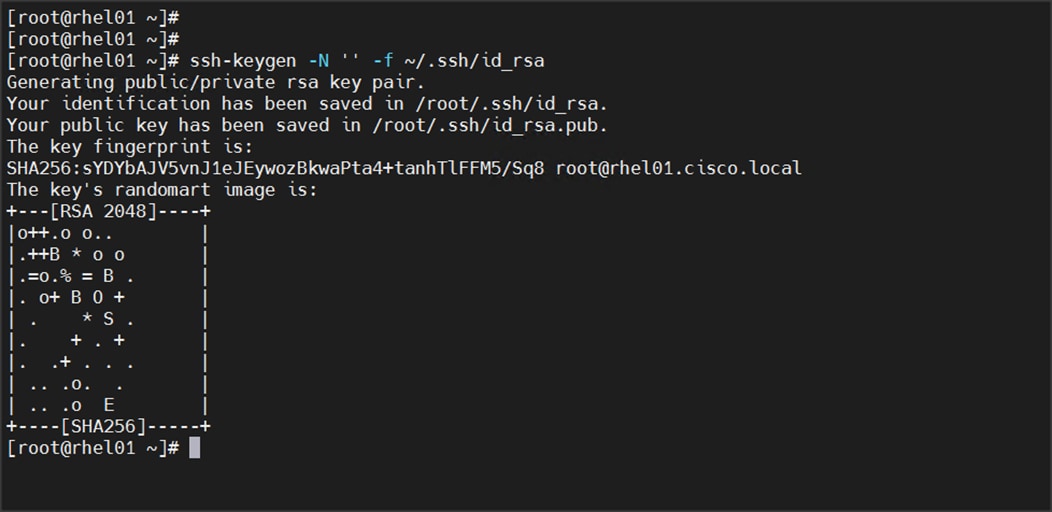
3. Run the following command from the admin node to copy the public key id_rsa.pub to all the nodes of the cluster. ssh-copy-id appends the keys to the remote-hosts .ssh/authorized_keys.
# for i in {01..04}; do echo "copying rhelnn$i.cisco.local"; ssh-copy-id -i ~/.ssh/id_rsa.pub root@rhelnn$i.cisco.local; done;
# for i in {01..08}; do echo "copying rhel$i.cisco.local"; ssh-copy-id -i ~/.ssh/id_rsa.pub root@rhel$i.cisco.local; done;
4. Enter yes for Are you sure you want to continue connecting (yes/no)?
5. Enter the password of the remote host.
Create a Red Hat Enterprise Linux (RHEL) 7.8 Local Repository
To create a repository using RHEL DVD or ISO on the admin node (in this deployment rhelnn01 is used for this purpose), create a directory with all the required RPMs, run the createrepo command and then publish the resulting repository.
To create a RHEL 7.8 local repository, follow these steps:
1. Log into rhelnn01. Create a directory that would contain the repository.
# mkdir -p /var/www/html/rhelrepo
2. Copy the contents of the Red Hat DVD to /var/www/html/rhelrepo
3. Alternatively, if you have access to a Red Hat ISO Image, Copy the ISO file to rhelnn01.
4. Log back into rhelnn01 and create the mount directory.
# scp rhel-server-7.8-x86_64-dvd.iso rhelnn01:/root/
# mkdir -p /mnt/rheliso
# mount -t iso9660 -o loop /root/rhel-server-7.8-x86_64-dvd.iso /mnt/rheliso/
5. Copy the contents of the ISO to the /var/www/html/rhelrepo directory.
# cp -r /mnt/rheliso/* /var/www/html/rhelrepo
6. On rhelnn01 create a .repo file to enable the use of the yum command.
# vi /var/www/html/rhelrepo/rheliso.repo
[rhel7.8]
name=Red Hat Enterprise Linux 7.8
baseurl=http://10.15.1.101/rhelrepo
gpgcheck=0
enabled=1
7. Copy rheliso.repo file from /var/www/html/rhelrepo to /etc/yum.repos.d on rhelnn01.
# cp /var/www/html/rhelrepo/rheliso.repo /etc/yum.repos.d/
![]() Based on this repository file, yum requires httpd to be running on rhelnn01 for other nodes to access the repository.
Based on this repository file, yum requires httpd to be running on rhelnn01 for other nodes to access the repository.
8. To make use of repository files on rhelnn01 without httpd, edit the baseurl of repo file /etc/yum.repos.d/rheliso.repo to point repository location in the file system.
![]() This step is required to install software on Admin Node (rhelnn01) using the repo (such as httpd, create-repo, and so on.)
This step is required to install software on Admin Node (rhelnn01) using the repo (such as httpd, create-repo, and so on.)
# vi /etc/yum.repos.d/rheliso.repo
[rhel7.8]
name=Red Hat Enterprise Linux 7.8
baseurl=file:///var/www/html/rhelrepo
gpgcheck=0
enabled=1
Create the Red Hat Repository Database
To create the Red Hat repository database, follow these steps:
1. Install the createrepo package on admin node (rhelnn01). Use it to regenerate the repository database(s) for the local copy of the RHEL DVD contents.
# yum -y install createrepo
2. Run createrepo on the RHEL repository to create the repo database on admin node.
# cd /var/www/html/rhelrepo
# createrepo .
Figure 57. createrepo

To set up Ansible, follow these steps:
1. Download Ansible rpm from the following link: https://releases.ansible.com/ansible/rpm/release/epel-7-x86_64/ansible-2.9.18-1.el7.ans.noarch.rpm
# wget https://releases.ansible.com/ansible/rpm/release/epel-7-x86_64/ansible-2.9.18-1.el7.ans.noarch.rpm
2. Run the following command to install ansible:
# yum localinstall -y ansible-2.9.18-1.el7.ans.noarch.rpm
3. Verify Ansible installation by running the following commands:
# [root@rhelnn01 ~]# ansible --version
ansible 2.9.18
config file = /etc/ansible/ansible.cfg
configured module search path = [u'/root/.ansible/plugins/modules', u'/usr/share/ansible/plugins/modules']
ansible python module location = /usr/lib/python2.7/site-packages/ansible
executable location = /usr/bin/ansible
python version = 2.7.5 (default, Aug 13 2020, 02:51:10) [GCC 4.8.5 20150623 (Red Hat 4.8.5-39)]
[root@rhelnn01 ~]#
[root@rhelnn01 pkg]#
# ansible localhost -m ping
localhost | SUCCESS => {
"changed": false,
"ping": "pong"
}
4. Prepare the host inventory file for Ansible as shown below. Various host groups have been created based on any specific installation requirements of certain hosts.
[root@rhelnn01 ~]# cat /etc/ansible/hosts
[admin]
rhelnn01.cdpdc.cisco.local
[namenodes]
rhelnn01.cisco.local
rhelnn02.cisco.local
rhelnn03.cisco.local
rhelnn04.cisco.local
[datanodes]
rhel01.cisco.local
rhel02.cisco.local
rhel03.cisco.local
rhel04.cisco.local
rhel05.cisco.local
rhel06.cisco.local
rhel07.cisco.local
rhel08.cisco.local
[nodes]
rhel01.cisco.local
rhel02.cisco.local
rhel03.cisco.local
rhel04.cisco.local
rhel05.cisco.local
rhel06.cisco.local
rhel07.cisco.local
rhel08.cisco.local
rhelnn01.cisco.local
rhelnn02.cisco.local
rhelnn03.cisco.local
rhelnn04.cisco.local
5. Verify host group by running the following commands.
# ansible datanodes -m ping
Setting up the RHEL repository on the admin node requires httpd. To set up RHEL repository on the admin node, follow these steps:
1. Install httpd on the admin node to host repositories:
![]() The Red Hat repository is hosted using HTTP on the admin node; this machine is accessible by all the hosts in the cluster.
The Red Hat repository is hosted using HTTP on the admin node; this machine is accessible by all the hosts in the cluster.
# yum –y install httpd
2. Add ServerName and make the necessary changes to the server configuration file:
# vi /etc/httpd/conf/httpd.conf
ServerName 10.15.1.101:80
Start httpd:
# service httpd start
# chkconfig httpd on
![]() The default Linux firewall settings are too restrictive for any Hadoop deployment. Since the Cisco UCS Big Data deployment will be in its own isolated network there is no need for that additional firewall.
The default Linux firewall settings are too restrictive for any Hadoop deployment. Since the Cisco UCS Big Data deployment will be in its own isolated network there is no need for that additional firewall.
# ansible all -m command -a "firewall-cmd --zone=public --add-port=80/tcp --permanent"
# ansible all -m command -a "firewall-cmd --reload"
# ansible all -m command -a "systemctl disable firewalld"
Set Up All Nodes to use the RHEL Repository
To set up all noes to use the RHEL repository, follow these steps:
![]() Based on this repository file, yum requires httpd to be running on rhelnn01 for other nodes to access the repository.
Based on this repository file, yum requires httpd to be running on rhelnn01 for other nodes to access the repository.
1. Copy the rheliso.repo to all the nodes of the cluster:
# ansible nodes -m copy -a "src=/var/www/html/rhelrepo/rheliso.repo dest=/etc/yum.repos.d/."
2. Copy the /etc/hosts file to all nodes:
# ansible nodes -m copy -a "src=/etc/hosts dest=/etc/hosts"
3. Purge the yum caches:
# ansible nodes -a “yum clean all”
# ansible nodes -a “yum repolist”
![]() While the suggested configuration is to disable SELinux as shown below, if for any reason SELinux needs to be enabled on the cluster, run the following command to make sure that the httpd can read the Yum repofiles.
While the suggested configuration is to disable SELinux as shown below, if for any reason SELinux needs to be enabled on the cluster, run the following command to make sure that the httpd can read the Yum repofiles.
#chcon -R -t httpd_sys_content_t /var/www/html/
![]() SELinux must be disabled during the install procedure and cluster setup. SELinux can be enabled after installation and while the cluster is running.
SELinux must be disabled during the install procedure and cluster setup. SELinux can be enabled after installation and while the cluster is running.
SELinux can be disabled by editing /etc/selinux/config and changing the SELINUX line to SELINUX=disabled.
To disable SELinux, follow these steps:
1. The following command will disable SELINUX on all nodes:
# ansible nodes -m shell -a "sed –i 's/SELINUX=enforcing/SELINUX=disabled/g' /etc/selinux/config"
# ansible nodes -m shell -a "setenforce 0"
![]() The above command may fail if SELinux is already disabled. This requires reboot to take effect.
The above command may fail if SELinux is already disabled. This requires reboot to take effect.
2. Reboot the machine, if needed for SELinux to be disabled in case it does not take effect. It can be checked using the following command:
# [root@rhelnn01 ~]# ansible nodes -a "sestatus"
rhel01.cisco.local | CHANGED | rc=0 >>
SELinux status: disabled
rhel05.cisco.local | CHANGED | rc=0 >>
SELinux status: disabled
rhel03.cisco.local | CHANGED | rc=0 >>
SELinux status: disabled
rhel02.cisco.local | CHANGED | rc=0 >>
SELinux status: disabled
rhel04.cisco.local | CHANGED | rc=0 >>
SELinux status: disabled
rhelnn01.cisco.local | CHANGED | rc=0 >>
SELinux status: disabled
rhel06.cisco.local | CHANGED | rc=0 >>
SELinux status: disabled
rhel07.cisco.local | CHANGED | rc=0 >>
SELinux status: disabled
rhel08.cisco.local | CHANGED | rc=0 >>
SELinux status: disabled
rhelnn02.cisco.local | CHANGED | rc=0 >>
SELinux status: disabled
rhelnn03.cisco.local | CHANGED | rc=0 >>
SELinux status: disabled
rhelnn04.cisco.local | CHANGED | rc=0 >>
SELinux status: disabled
[root@rhelnn01 ~]#
Upgrade the Cisco Network Driver for VIC1457
The latest Cisco Network driver is required for performance and updates. The latest drivers can be downloaded from the link below:
https://software.cisco.com/download/home/286318800/type/283853158/release/4.1(3b)
In the ISO image, the required driver kmod-enic-4.0.0.14-802.74.rhel7u8.x86_64.rpm can be located at \Network\Cisco\VIC\RHEL\RHEL7.8\.
To upgrade the Cisco Network Driver for VIC1457, follow these steps:
1. From a node connected to the Internet, download, extract, and transfer kmod-enic-.rpm to rhelnn01 (admin node).
2. Copy the rpm on all nodes of the cluster using the following Ansible commands. For this example, the rpm is assumed to be in present working directory of rhelnn01:
[root@rhelnn01 ~]# ansible all -m copy -a "src=/root/kmod-enic-4.0.0.14-802.74.rhel7u8.x86_64.rpm dest=/root/."
3. Use the yum module to install the enic driver rpm file on all the nodes through Ansible:
[root@rhelnn01 ~]# ansible all –m yum –a “name=/root/ kmod-enic-4.0.0.14-802.74.rhel7u8.x86_64.rpm state=present”
4. Make sure that the above installed version of kmod-enic driver is being used on all nodes by running the command "modinfo enic" on all nodes:
[root@rhelnn01 rhel]# ansible all -m shell -a "modinfo enic | head -5"
rhelnn01.cisco.local | CHANGED | rc=0 >>
filename: /lib/modules/3.10.0-1127.el7.x86_64/extra/enic/enic.ko
version: 4.0.0.14-802.74
license: GPL v2
author: Scott Feldman <scofeldm@cisco.com>
description: Cisco VIC Ethernet NIC Driver
rhelnn04.cisco.local | CHANGED | rc=0 >>
filename: /lib/modules/3.10.0-1127.el7.x86_64/extra/enic/enic.ko
version: 4.0.0.14-802.74
license: GPL v2
author: Scott Feldman <scofeldm@cisco.com>
description: Cisco VIC Ethernet NIC Driver
rhel01.cisco.local | CHANGED | rc=0 >>
filename: /lib/modules/3.10.0-1127.el7.x86_64/extra/enic/enic.ko
version: 4.0.0.14-802.74
license: GPL v2
author: Scott Feldman <scofeldm@cisco.com>
description: Cisco VIC Ethernet NIC Driver
![]() It is recommended to download the kmod-megaraid driver for higher performance on Name nodes. The RPM can be found in the same package at: \Storage\LSI\Cisco_Storage_12G_SAS_RAID_controller\RHEL\RHEL7.7\ kmod-megaraid_sas-07.710.06.00_el7.7-1.x86_64.rpm:
It is recommended to download the kmod-megaraid driver for higher performance on Name nodes. The RPM can be found in the same package at: \Storage\LSI\Cisco_Storage_12G_SAS_RAID_controller\RHEL\RHEL7.7\ kmod-megaraid_sas-07.710.06.00_el7.7-1.x86_64.rpm:
5. Copy the rpm on all nodes of the cluster using the following Ansible commands. For this example, the rpm is assumed to be in present working directory of rhelnn01:
[root@rhelnn01 ~]# ansible namenodes -m copy -a "src=/root/kmod-megaraid_sas-07.710.06.00_el7.7-1.x86_64.rpm dest=/root/."
6. Use the yum module to install the enic driver rpm file on all the nodes through Ansible:
[root@rhelnn01 ~]# ansible namenodes –m yum –a “name=/root/ kmod-megaraid_sas-07.710.06.00_el7.7-1.x86_64.rpm state=present”
7. Make sure that the above installed version of kmod-megaraid driver is being used on all nodes by running the command "modinfo megaraid_sas" on all nodes:
[root@rhelnn01 ~]# ansible all -m shell -a "modinfo megaraid_sas | head -5"
To setup JAVA, follow these steps:
![]() Cloudera Data Platform Private Cloud Base 7 requires JAVA 8 or 11.
Cloudera Data Platform Private Cloud Base 7 requires JAVA 8 or 11.
1. Download jdk-11.0.10_linux-x64_bin.rpm and copy the rpm to admin node (rhelnn01) from the link: https://www.oracle.com/java/technologies/javase-jdk11-downloads.html#license-lightbox
2. Copy JDK rpm to all nodes:
# ansible nodes -m copy -a "src=/root/jdk-11.0.10_linux-x64_bin.rpm dest=/root/."
3. Extract and Install JDK all nodes:
# ansible all -m command -a "rpm -ivh jdk-11.0.10_linux-x64_bin.rpm"
rhelnn03.cisco.local | CHANGED | rc=0 >>
warning: jdk-11.0.10_linux-x64_bin.rpm: Header V3 RSA/SHA256 Signature, key ID ec551f03: NOKEY
Preparing... ################################# [100%]
Updating / installing...
1:jdk-11.0.10-2000:11.0.10-ga ################################# [100%]
ec551f03: NOKEY
4. Create the following files java-set-alternatives.sh and java-home.sh on admin node (rhelnn01):
# vi java-set-alternatives.sh
#!/bin/bash
for item in java javac javaws jar jps javah javap jcontrol jconsole jdb; do
rm -f /var/lib/alternatives/$item
alternatives --install /usr/bin/$item $item /usr/java/jdk-11.0.10/bin/$item 9
alternatives --set $item /usr/java/jdk-11.0.10/bin/$item
done
# vi java-home.sh
export JAVA_HOME=/usr/java/jdk-11.0.10
5. Make the two java scripts created above executable:
chmod 755 ./java-set-alternatives.sh ./java-home.sh
6. Copying java-set-alternatives.sh to all nodes.
ansible nodes -m copy -a "src=/root/java-set-alternatives.sh dest=/root/."
ansible nodes -m file -a "dest=/root/java-set-alternatives.sh mode=755"
ansible nodes -m copy -a "src=/root/java-home.sh dest=/root/."
ansible nodes -m file -a "dest=/root/java-home.sh mode=755"
7. Setup Java Alternatives:
[root@rhelnn01 ~]# ansible all -m shell -a "/root/java-set-alternatives.sh"
8. Make sure correct java is setup on all nodes (should point to newly installed java path).
# ansible all -m shell -a "alternatives --display java | head -2"
rhelnn01.cisco.local | CHANGED | rc=0 >>
java - status is manual.
link currently points to /usr/java/jdk1.8.0_281-amd64/bin/java
rhelnn04.cisco.local | CHANGED | rc=0 >>
java - status is manual.
link currently points to /usr/java/jdk1.8.0_281-amd64/bin/java
rhel01.cisco.local | CHANGED | rc=0 >>
java - status is manual.
link currently points to /usr/java/jdk1.8.0_281-amd64/bin/java
9. Setup JAVA_HOME on all nodes.
# ansible all -m copy -a "src=/root/java-home.sh dest=/etc/profile.d"
10. Display JAVA_HOME on all nodes.
# ansible all -m command -a "echo $JAVA_HOME"
rhel19.cdpdc.cisco.local | CHANGED | rc=0 >>
/usr/java/jdk1.8.0_281-amd64
11. Display current java –version.
# ansible all -m command -a "java -version"
rhelnn04.cdip-ozone.cisco.local | CHANGED | rc=0 >>
java version "11.0.10" 2021-01-19 LTS
Java(TM) SE Runtime Environment 18.9 (build 11.0.10+8-LTS-162)
Java HotSpot(TM) 64-Bit Server VM 18.9 (build 11.0.10+8-LTS-162, mixed mode)
rhelnn01.cdip-ozone.cisco.local | CHANGED | rc=0 >>
java version "11.0.10" 2021-01-19 LTS
Java(TM) SE Runtime Environment 18.9 (build 11.0.10+8-LTS-162)
Java HotSpot(TM) 64-Bit Server VM 18.9 (build 11.0.10+8-LTS-162, mixed mode)
Syslog must be enabled on each node to preserve logs regarding killed processes or failed jobs. Modern versions such as syslog-ng and rsyslog are possible, making it more difficult to be sure that a syslog daemon is present.
Use one of the following commands to confirm that the service is properly configured:
# ansible all -m command -a "rsyslogd –v"
# ansible all -m command -a "service rsyslog status"
On each node, ulimit -n specifies the number of inodes that can be opened simultaneously. With the default value of 1024, the system appears to be out of disk space and shows no inodes available. This value should be set to 64000 on every node.
Higher values are unlikely to result in an appreciable performance gain.
To set ulimit, follow these steps:
1. For setting the ulimit on Redhat, edit /etc/security/limits.conf on admin node rhelnn01 and add the following lines:
# vi /etc/security/limits.conf
* soft nofile 1048576
* hard nofile 1048576
2. Copy the /etc/security/limits.conf file from admin node (rhelnn01) to all the nodes using the following command:
# ansible nodes -m copy -a "src=/etc/security/limits.conf dest=/etc/security/limits.conf"
3. Make sure that the /etc/pam.d/su file contains the following settings:
# cat /etc/pam.d/su
#%PAM-1.0
auth sufficient pam_rootok.so
# Uncomment the following line to implicitly trust users in the "wheel" group.
#auth sufficient pam_wheel.so trust use_uid
# Uncomment the following line to require a user to be in the "wheel" group.
#auth required pam_wheel.so use_uid
auth include system-auth
auth include postlogin
account sufficient pam_succeed_if.so uid = 0 use_uid quiet
account include system-auth
password include system-auth
session include system-auth
session include postlogin
session optional pam_xauth.so
![]() The ulimit values are applied on a new shell, running the command on a node on an earlier instance of a shell will show old values.
The ulimit values are applied on a new shell, running the command on a node on an earlier instance of a shell will show old values.
Adjusting the tcp_retries parameter for the system network enables faster detection of failed nodes. Given the advanced networking features of UCS, this is a safe and recommended change (failures observed at the operating system layer are most likely serious rather than transitory).
To set TCP retries, follow these steps:
![]() On each node, set the number of TCP retries to 5 can help detect unreachable nodes with less latency.
On each node, set the number of TCP retries to 5 can help detect unreachable nodes with less latency.
1. Edit the file /etc/sysctl.conf and on admin node rhelnn01 and add the following lines:
net.ipv4.tcp_retries2=5
Copy the /etc/sysctl.conf file from admin node (rhelnn01) to all the nodes using the following command:
# ansible nodes -m copy -a "src=/etc/sysctl.conf dest=/etc/sysctl.conf"
2. Load the settings from default sysctl file /etc/sysctl.conf by running the following command:
# ansible nodes -m command -a "sysctl -p"
To disable IPv6 defaults, follow these steps:
1. Run the following command:
# ansible all -m shell -a "echo 'net.ipv6.conf.all.disable_ipv6 = 1' >> /etc/sysctl.conf"
# ansible all -m shell -a "echo 'net.ipv6.conf.default.disable_ipv6 = 1' >> /etc/sysctl.conf"
# ansible all -m shell -a "echo 'net.ipv6.conf.lo.disable_ipv6 = 1' >> /etc/sysctl.conf"
2. Load the settings from default sysctl file /etc/sysctl.conf:
# ansible all -m shell -a "sysctl –p"
To disable swapping, follow these steps:
1. Run the following on all nodes. Variable vm.swappiness defines how often swap should be used, 60 is default:
# ansible all -m shell -a "echo 'vm.swappiness=0' >> /etc/sysctl.conf"
2. Load the settings from default sysctl file /etc/sysctl.conf and verify the content of sysctl.conf:
# ansible all -m shell -a "sysctl –p"
# ansible all -m shell -a "cat /etc/sysctl.conf"
To disable Memory Overcommit, follow these steps:
1. Run the following on all nodes. Variable vm.overcommit_memory=0
# ansible all -m shell -a "echo 'vm.overcommit_memory=0' >> /etc/sysctl.conf"
2. Load the settings from default sysctl file /etc/sysctl.conf and verify the content of sysctl.conf:
# ansible all -m shell -a "sysctl –p"
# ansible all -m shell -a "cat /etc/sysctl.conf"
rhel05.cisco.local | CHANGED | rc=0 >>
# sysctl settings are defined through files in
# /usr/lib/sysctl.d/, /run/sysctl.d/, and /etc/sysctl.d/.
#
# Vendors settings live in /usr/lib/sysctl.d/.
# To override a whole file, create a new file with the same in
# /etc/sysctl.d/ and put new settings there. To override
# only specific settings, add a file with a lexically later
# name in /etc/sysctl.d/ and put new settings there.
#
# For more information, see sysctl.conf(5) and sysctl.d(5).
net.ipv4.tcp_retries2=5
net.ipv6.conf.all.disable_ipv6 = 1
net.ipv6.conf.default.disable_ipv6 = 1
net.ipv6.conf.lo.disable_ipv6 = 1
vm.swappiness=0
vm.overcommit_memory=0
Disable Transparent Huge Pages
Disabling Transparent Huge Pages (THP) reduces elevated CPU usage caused by THP.
To disable Transparent Huge Pages, follow these steps:
1. You must run the following commands for every reboot; copy this command to /etc/rc.local so they are executed automatically for every reboot:
# ansible all -m shell -a "echo never > /sys/kernel/mm/transparent_hugepage/enabled”
# ansible all -m shell -a "echo never > /sys/kernel/mm/transparent_hugepage/defrag"
2. On the Admin node, run the following commands:
#rm –f /root/thp_disable
#echo "echo never > /sys/kernel/mm/transparent_hugepage/enabled" >>
/root/thp_disable
#echo "echo never > /sys/kernel/mm/transparent_hugepage/defrag " >>
/root/thp_disable
3. Copy file to each node:
# ansible nodes -m copy -a "src=/root/thp_disable dest=/root/thp_disable"
Append the content of file thp_disable to /etc/rc.d/rc.local:
# ansible nodes -m shell -a "cat /root/thp_disable >> /etc/rc.d/rc.local"
# ansible nodes -m shell -a "chmod +x /etc/rc.d/rc.local"
The Network Time Protocol (NTP) is used to synchronize the time of all the nodes within the cluster. The Network Time Protocol daemon (ntpd) sets and maintains the system time of day in synchronism with the timeserver located in the admin node (rhelnn01). Configuring NTP is critical for any Hadoop Cluster. If server clocks in the cluster drift out of sync, serious problems will occur with HBase and other services.
To configure NTP, follow these steps:
# ansible all -m yum -a "name=ntp state=present"
![]() Installing an internal NTP server keeps your cluster synchronized even when an outside NTP server is inaccessible.
Installing an internal NTP server keeps your cluster synchronized even when an outside NTP server is inaccessible.
1. Configure /etc/ntp.conf on the admin node only with the following contents:
# vi /etc/ntp.conf
driftfile /var/lib/ntp/drift
restrict 127.0.0.1
restrict -6 ::1
server 127.127.1.0
fudge 127.127.1.0 stratum 10
includefile /etc/ntp/crypto/pw
keys /etc/ntp/keys
2. Create /root/ntp.conf on the admin node and copy it to all nodes:
# vi /root/ntp.conf
server 10.15.1.101
driftfile /var/lib/ntp/drift
restrict 127.0.0.1
restrict -6 ::1
includefile /etc/ntp/crypto/pw
keys /etc/ntp/keys
3. Copy ntp.conf file from the admin node to /etc of all the nodes by executing the following commands in the admin node (rhelnn01):
# ansible nodes -m copy -a “src=/root/ntp.conf dest=/etc/ntp.conf”
4. Run the following to synchronize the time and restart NTP daemon on all nodes:
# ansible all -m service -a “name=ntpd state=stopped"
# ansible all -m command -a "ntpdate rhelnn01.cdpdc.cisco.local"
# ansible all -m service -a “name=ntpd state=started”
5. Make sure to restart of NTP daemon across reboots:
# ansible all -a "systemctl enable ntpd"
6. Verify NTP is up and running in all nodes by running the following commands:
# ansible all -a "systemctl status ntpd"
![]() Alternatively, the new Chrony service can be installed, which is quicker to synchronize clocks in mobile and virtual systems.
Alternatively, the new Chrony service can be installed, which is quicker to synchronize clocks in mobile and virtual systems.
7. Install the Chrony service:
# ansible all -m yum -a "name=chrony state=present"
8. Activate the Chrony service at boot:
# ansible all -a "systemctl enable chronyd"
9. Start the Chrony service:
# ansible all -m service -a "name=chronyd state=started"
# systemctl start chronyd
The Chrony configuration is in the /etc/chrony.conf file, configured similar to /etc/ntp.conf.
This section explains the steps needed to install StorCLI (Storage Command Line Tool) which is a command line interface designed to be easy to use, consistent, and script. For more details, go to: https://docs.broadcom.com/docs/12352476
To install StorCLI, follow these steps:
1. Download StorCLI: https://www.broadcom.com/support/download-search/?pg=&pf=&pn=&po=&pa=&dk=storcli.
2. Extract the .zip file and copy storcli-1.23.02-1.noarch.rpm from the linux directory.
3. Download StorCLI and its dependencies and transfer to Admin node:
#scp storcli-1.23.02-1.noarch.rpm rhelnn01:/root/
4. Copy storcli rpm to all the nodes using the following commands:
# ansible all -m copy -a "src=/root/storcli-1.23.02-1.noarch.rpm dest=/root/."
5. Run this command to install storcli on all the nodes:
# ansible all -m shell -a "rpm -ivh storcli-1.23.02-1.noarch.rpm"
6. Run this command to copy storcli64 to root directory:
# ansible all -m shell -a "cp /opt/MegaRAID/storcli/storcli64 /root/."
7. Run this command to check the state of the disks:
# ansible all -m shell -a "./storcli64 /c0 show all"
![]() The Cisco UCS Manager configuration explains the steps to deploy the required storage configuration via Storage Policy and Storage Profile attached to Service Profile Template for NameNode(s), Management Node(s), GPU Node(s) and DataNode(s).
The Cisco UCS Manager configuration explains the steps to deploy the required storage configuration via Storage Policy and Storage Profile attached to Service Profile Template for NameNode(s), Management Node(s), GPU Node(s) and DataNode(s).
Configure the Filesystem for NameNodes and DataNodes
The following script formats and mounts the available volumes on each node whether it is NameNode or Data node. OS boot partition will be skipped. All drives are mounted based on their UUID as /data/disk1, /data/disk2, etc. To configure the filesystem for NameNodes and DataNodes, follow these steps:
1. On the Admin node, create a file containing the following script:
#vi /root/driveconf.sh
To create partition tables and file systems on the local disks supplied to each of the nodes, run the following script as the root user on each node:
![]() This script assumes there are no partitions already existing on the data volumes. If there are partitions, delete them before running the script. This process is in section Delete Partitions.
This script assumes there are no partitions already existing on the data volumes. If there are partitions, delete them before running the script. This process is in section Delete Partitions.
![]() Cloudera recommends two NVMe drives for the Ozone master nodes and Ozone data nodes in Raid 1 but in case of SSDs are installed for Ozone metadata which will require the run partition script below with edits so that Raid 1 based virtual drive volume created out of two SSDs can be presented separately as /ozone/metadata partition for example.
Cloudera recommends two NVMe drives for the Ozone master nodes and Ozone data nodes in Raid 1 but in case of SSDs are installed for Ozone metadata which will require the run partition script below with edits so that Raid 1 based virtual drive volume created out of two SSDs can be presented separately as /ozone/metadata partition for example.
#vi /root/driveconf.sh
#!/bin/bash
[[ "-x" == "${1}" ]] && set -x && set -v && shift 1
count=1
for X in /sys/class/scsi_host/host?/scan
do
echo '- - -' > ${X}
done
for X in /dev/sd?
do
list+=$(echo $X " ")
done
for X in /dev/sd??
do
list+=$(echo $X " ")
done
for X in $list
do
echo "========"
echo $X
echo "========"
if [[ -b ${X} && `/sbin/parted -s ${X} print quit|/bin/grep -c boot` -
ne 0
]]
then
echo "$X bootable - skipping."
continue
else
Y=${X##*/}1
echo "Formatting and Mounting Drive => ${X}"
166
/sbin/mkfs.xfs –f ${X}
(( $? )) && continue
#Identify UUID
UUID=`blkid ${X} | cut -d " " -f2 | cut -d "=" -f2 | sed 's/"//g'`
/bin/mkdir -p /data/disk${count}
(( $? )) && continue
echo "UUID of ${X} = ${UUID}, mounting ${X} using UUID on
/data/disk${count}"
/bin/mount -t xfs -o inode64,noatime,nobarrier -U ${UUID}
/data/disk${count}
(( $? )) && continue
echo "UUID=${UUID} /data/disk${count} xfs inode64,noatime,nobarrier 0
0" >> /etc/fstab
((count++))
fi
done
2. Create and run following script on each node to partition NVMe drives for Ozone metadata:
echo "Formatting and Mounting Drive => /dev/nvme0n1"
/sbin/mkfs.xfs -f /dev/nvme0n1
(( $? )) && continue
#Identify UUID
UUID=`blkid /dev/nvme0n1 | cut -d " " -f2 | cut -d "=" -f2 | sed 's/"//g'`
echo "Make Directory /ozone/metata"
/bin/mkdir -p /ozone/metata
(( $? )) && continue
echo "UUID of /dev/nvme0n1 = ${UUID}, mounting nvme0n1 using UUID on /ozone/metadata"
/bin/mount -t xfs -o inode64,noatime -U ${UUID} /temp/nvme1
(( $? )) && continue
echo "Creating fstab entry ${UUID} /ozone/metata xfs inode64,noatime 0 0"
echo "UUID=${UUID} /ozone/metata xfs inode64,noatime 0 0" >> /etc/fstab
done
3. Run the following command to copy driveconf.sh to all the nodes:
# chmod 755 /root/driveconf.sh
# ansible datanodes -m copy -a src=/root/driveconf.sh dest=/root/.”
# ansible nodes -m file -a "dest=/root/driveconf.sh mode=755"
4. Run the following command from the admin node to run the script across all data nodes:
# ansible datanodes -m shell -a “/root/driveconf.sh”
5. Run the following from the admin node to list the partitions and mount points:
# ansible datanodes -m shell -a “df –h”
# ansible datanodes -m shell -a “mount”
# ansible datanodes -m shell -a “cat /etc/fstab”
To delete a partition, follow this step:
1. Run the mount command (‘mount’) to identify which drive is mounted to which device /dev/sd<?> and umount the drive for which partition is to be deleted and run fdisk to delete as shown below.
![]() Be sure not to delete the OS partition since this will wipe out the OS.
Be sure not to delete the OS partition since this will wipe out the OS.
# mount
# umount /data/disk1 (disk1 shown as example)
#(echo d; echo w;) | sudo fdisk /dev/sd<?>
This section explains the steps to create the script cluster_verification.sh that helps to verify the CPU, memory, NIC, and storage adapter settings across the cluster on all nodes. This script also checks additional prerequisites such as NTP status, SELinux status, ulimit settings, JAVA_HOME settings and JDK version, IP address and hostname resolution, Linux version and firewall settings.
To verify a cluster, follow these steps:
![]() The following script uses cluster shell (clush) which needs to be installed and configured.
The following script uses cluster shell (clush) which needs to be installed and configured.
1. Create the script cluster_verification.sh as shown, on the Admin node (rhelnn01).
#vi cluster_verification.sh
#!/bin/bash
shopt -s expand_aliases,
# Setting Color codes
green='\e[0;32m'
red='\e[0;31m'
NC='\e[0m' # No Color
echo -e "${green} === Cisco UCS Integrated Infrastructure for Big Data and Analytics \ Cluster Verification === ${NC}"
echo ""
echo ""
echo -e "${green} ==== System Information ==== ${NC}"
echo ""
echo ""
echo -e "${green}System ${NC}"
clush -a -B " `which dmidecode` |grep -A2 '^System Information'"
echo ""
echo ""
echo -e "${green}BIOS ${NC}"
clush -a -B " `which dmidecode` | grep -A3 '^BIOS I'"
echo ""
echo ""
echo -e "${green}Memory ${NC}"
clush -a -B "cat /proc/meminfo | grep -i ^memt | uniq"
echo ""
echo ""
echo -e "${green}Number of Dimms ${NC}"
clush -a -B "echo -n 'DIMM slots: '; `which dmidecode` |grep -c \ '^[[:space:]]*Locator:'"
clush -a -B "echo -n 'DIMM count is: '; `which dmidecode` | grep \ "Size"| grep -c "MB""
clush -a -B " `which dmidecode` | awk '/Memory Device$/,/^$/ {print}' |\ grep -e '^Mem' -e Size: -e Speed: -e Part | sort -u | grep -v -e 'NO \ DIMM' -e 'No Module Installed' -e Unknown"
echo ""
echo ""
# probe for cpu info #
echo -e "${green}CPU ${NC}"
clush -a -B "grep '^model name' /proc/cpuinfo | sort -u"
echo ""
clush -a -B "`which lscpu` | grep -v -e op-mode -e ^Vendor -e family -e\ Model: -e Stepping: -e BogoMIPS -e Virtual -e ^Byte -e '^NUMA node(s)'"
echo ""
echo ""
# probe for nic info #
echo -e "${green}NIC ${NC}"
clush -a -B "`which ifconfig` | egrep '(^e|^p)' | awk '{print \$1}' | \ xargs -l `which ethtool` | grep -e ^Settings -e Speed"
echo ""
clush -a -B "`which lspci` | grep -i ether"
echo ""
echo ""
# probe for disk info #
echo -e "${green}Storage ${NC}"
clush -a -B "echo 'Storage Controller: '; `which lspci` | grep -i -e \ raid -e storage -e lsi"
echo ""
clush -a -B "dmesg | grep -i raid | grep -i scsi"
echo ""
clush -a -B "lsblk -id | awk '{print \$1,\$4}'|sort | nl"
echo ""
echo ""
echo -e "${green} ================ Software ======================= ${NC}"
echo ""
echo ""
echo -e "${green}Linux Release ${NC}"
clush -a -B "cat /etc/*release | uniq"
echo ""
echo ""
echo -e "${green}Linux Version ${NC}"
clush -a -B "uname -srvm | fmt"
echo ""
echo ""
echo -e "${green}Date ${NC}"
clush -a -B date
echo ""
echo ""
echo -e "${green}NTP Status ${NC}"
clush -a -B "ntpstat 2>&1 | head -1"
echo ""
echo ""
echo -e "${green}SELINUX ${NC}"
clush -a -B "echo -n 'SElinux status: '; grep ^SELINUX= \ /etc/selinux/config 2>&1"
echo ""
echo ""
clush -a -B "echo -n 'CPUspeed Service: '; `which service` cpuspeed \ status 2>&1"
clush -a -B "echo -n 'CPUspeed Service: '; `which chkconfig` --list \ cpuspeed 2>&1"
echo ""
echo ""
echo -e "${green}Java Version${NC}"
clush -a -B 'java -version 2>&1; echo JAVA_HOME is ${JAVA_HOME:-Not \ Defined!}'
echo ""
echo ""
echo -e "${green}Hostname LoOKup${NC}"
clush -a -B " ip addr show"
echo ""
echo ""
echo -e "${green}Open File Limit${NC}"
clush -a -B 'echo -n "Open file limit(should be >32K): "; ulimit -n'
2. Change permissions to executable:
# chmod 755 cluster_verification.sh
3. Run the Cluster Verification tool from the admin node. This can be run before starting Hadoop to identify any discrepancies in Post OS Configuration between the servers or during troubleshooting of any cluster / Hadoop issues:
#./cluster_verification.sh
Install Cloudera Data Platform Private Cloud Base
This section provides instructions for installing Cloudera software, including Cloudera Manager, Cloudera Runtime, and other managed services, in a production environment.
Review the Cloudera Production Installation: Before You Install steps prior to the production installation of Cloudera Manager, Cloudera Runtime, and other managed services, review the Cloudera Data Platform version 7 Requirements and Supported Versions, in addition to the Cloudera Data Platform Release Notes.
Prerequisites for CDP PvC Base Installation
This section details the prerequisites for the CDP PvC Base installation, such as setting up Cloudera Repo.
Cloudera Manager Repository
To setup the Cloudera Manager Repository, follow these steps:
1. From a host connected to the Internet, download the Cloudera’s repositories as shown below and transfer it to the admin node:
#mkdir -p /tmp/cloudera-repos/
2. Download Cloudera Manager Repository:
#cd /tmp/cloudera-repos/
# wget https://archive.cloudera.com/p/cm7/7.2.6/redhat7/yum/cloudera-manager-trial.repo
# reposync --config=./cloudera-manager-trial.repo --repoid=cloudera-manager
# wget https://archive.cloudera.com/ /p/cm7/7.2.6/allkeys.asc
![]() This downloads the Cloudera Manager RPMs needed for the Cloudera repository.
This downloads the Cloudera Manager RPMs needed for the Cloudera repository.
3. Run the following command to move the RPMs:
4. Copy the repository directory to the admin node (rhelnn01):
# scp -r /tmp/cloudera-repos/ rhelnn01:/var/www/html/
# mkdir -p /var/www/html/cloudera-repos/cloudera-manager (On admin node rhelnn01)
# scp allkeys.asc rhelnn01:/var/www/html/cloudera-repos/cloudera-manager/
5. On admin node (rhelnn01) run create repo command:
#cd /var/www/html/cloudera-repos/
#createrepo --baseurl http://10.15.1.101/cloudera-repos/cloudera-manager/ /var/www/html/cloudera-repos/cloudera-manager/
![]() Go to: http://10.15.1.101/cloudera-repos/cloudera-manager/ to verify the files.
Go to: http://10.15.1.101/cloudera-repos/cloudera-manager/ to verify the files.
6. Create the Cloudera Manager repo file with following contents:
# vi /var/www/html/cloudera-repos/cloudera-manager/cloudera-manager.repo
# cat /var/www/html/cloudera-repos/cloudera-manager/cloudera-manager.repo
[cloudera-repo]
name=Cloudera Manager 7.2.6
baseurl=http://10.15.1.101/cloudera-repos/cloudera-manager/
gpgcheck=0
enabled=1
Copy the file cloudera-repo.repo into /etc/yum.repos.d/ on the admin node to enable it to find the packages that are locally hosted:
#cp /var/www/html/cloudera-repos/cloudera-manager/cloudera-manager.repo /etc/yum.repos.d/
From the admin node copy the repo files to /etc/yum.repos.d/ of all the nodes of the cluster:
# ansible all -m copy -a "src=/etc/yum.repos.d/cloudera-manager.repo dest=/etc/yum.repos.d/."
Set Up the Local Parcels for CDP PvC Base 7.1.5
From a host connected the internet, download CDP PvC Base 7.1.5 parcels that are meant for RHEL7.8 from the URL: https://archive.cloudera.com/cdh7/7.1.5.0/parcels/ and place them in the directory /var/www/html/cloudera-repos/ " of the Admin node.
The following are the required files for RHEL7.8:
● CDH-7.1.5-1.cdh7.1.5.p0.7431829-el7.parcel
● CDH-7.1.5-1.cdh7.1.5.p0.7431829-el7.parcel.sha256
● manifest.json
To download parcels, follow these steps:
1. From a host connected to the Internet, download the Cloudera’s parcels as shown below and transfer it to the admin node:
#mkdir -p /tmp/cloudera-repos/CDH7.1.5.0parcels
2. Download parcels:
#cd /tmp/cloudera-repos/CDH7.1.5.0parcels
# wget https://archive.cloudera.com/p/cdh7/7.1.5.0/parcels/CDH-7.1.5-1.cdh7.1.5.p0.7431829-el7.parcel
# wget https://archive.cloudera.com/p/cdh7/7.1.5.0/parcels/CDH-7.1.5-1.cdh7.1.5.p0.7431829-el7.parcel.sha256
# wget https://archive.cloudera.com/p/cdh7/7.1.5.0/parcels/manifest.json
3. Copy /tmp/cloudera-repos/CDH7.1.5.0parcels to the admin node (rhelnn01):
# mkdir -p /var/www/html/cloudera-repos/cdh7/7.1.5.0/parcels/ (on rhelnn01)
# scp -r /tmp/cloudera-repos/CDH7.1.5.0parcels/ rhelnn01:/var/www/html/cloudera-repos/cdh7/7.1.5.0/parcels/
# chmod -R ugo+rX /var/www/html/cloudera-repos/cdh7
4. Verify that these files are accessible by visiting the URL http://10.15.1.101/cloudera-repos/cdh7/7.1.5.0/parcels/CDH7.1.5.0parcels/ in admin node.
5. Download Sqoop Connectors.
# mkdir -p /tmp/cloudera-repos/sqoop-connectors
# wget --recursive --no-parent --no-host-directories http://archive.cloudera.com/sqoop-connectors/parcels/latest/ -P /tmp/cloudera-repos/
6. Copy /tmp/cloudera-repos/sqoop-connectors to the admin node (rhelnn01).
# scp -r /tmp/cloudera-repos/sqoop-connectors rhelnn01:/var/www/html/cloudera-repos/
# sudo chmod -R ugo+rX /var/www/html/cloudera-repos/sqoop-connectors
Install and Configure Database for Cloudera Manager
You will set up the following for Cloudera Manager:
● Install the PostgreSQL Server
● Installing the psycopg2 Python Package
● Configure and Start the PostgreSQL Server
Install PostgreSQL Server
To install the PostgreSQL packages on the PostgreSQL server, follow these steps:
1. In the admin node where Cloudera Manager will be installed, use the following command to install PostgreSQL server.
#yum –y install postgresql12-server postgresql12-server
2. Install psycopg2 Python package 2.7.5 or higher if the lower version is installed.
# yum install -y python3-pip
# pip3 install psycopg2==2.7.5 --ignore-installed
![]() To check the installing dependencies for hue, go to: https://docs.cloudera.com/documentation/enterprise/upgrade/topics/ug_cdh_upgrade_hue_psycopg2.html
To check the installing dependencies for hue, go to: https://docs.cloudera.com/documentation/enterprise/upgrade/topics/ug_cdh_upgrade_hue_psycopg2.html
Configure and Start PostgreSQL Server
To configure and start the PostgreSQL server, follow these steps:
1. To configure and start the PostgreSQL Server, stop PostgreSQL server if it is running.
# systemctl stop postgresql-10.service
![]() Backup the existing database.
Backup the existing database.
![]() By default, PostgreSQL only accepts connections on the loopback interface. You must reconfigure PostgreSQL to accept connections from the fully qualified domain names (FQDN) of the hosts hosting the services for which you are configuring databases. If you do not make these changes, the services cannot connect to and use the database on which they depend.
By default, PostgreSQL only accepts connections on the loopback interface. You must reconfigure PostgreSQL to accept connections from the fully qualified domain names (FQDN) of the hosts hosting the services for which you are configuring databases. If you do not make these changes, the services cannot connect to and use the database on which they depend.
2. Make sure that LC_ALL is set to en_US.UTF-8 and initialize the database as follows:
# echo 'LC_ALL="en_US.UTF-8"' >> /etc/locale.conf
# sudo su -l postgres -c "postgresql-setup initdb"
3. To enable MD5 authentication, edit /var/lib/pgsql/data/pg_hba.conf by adding the following line:
# host all all 127.0.0.1/32 md5
![]() The host line specifying md5 authentication shown above must be inserted before this ident line:
The host line specifying md5 authentication shown above must be inserted before this ident line:
# host all all 127.0.0.1/32 ident
Failure to do so may cause an authentication error when running the scm_prepare_database.sh script. You can modify the contents of the md5 line shown above to support different configurations. For example, if you want to access PostgreSQL from a different host, replace 127.0.0.1 with your IP address and update postgresql.conf, which is typically found in the same place as pg_hba.conf, to include:
# listen_addresses = '*'
4. Configure settings to ensure your system performs as expected. Update these settings in the /var/lib/pgsql/data/postgresql.conf file. Settings vary based on cluster size and resources as follows:
max_connection – 500
shared_buffers - 1024 MB
wal_buffers - 16 MB
max_wal_size – 6GB (checkpoint_segments – 128)
checkpoint_completion_target - 0.9
![]() Refer to section Configuration and Starting the PostgreSQL Server, in the Cloudera Data Platform Private Cloud Base (CDP PvC Base) Installation guide: https://docs.cloudera.com/cdp-private-cloud-base/7.1.6/installation/topics/cdpdc-install-configure-databases.html
Refer to section Configuration and Starting the PostgreSQL Server, in the Cloudera Data Platform Private Cloud Base (CDP PvC Base) Installation guide: https://docs.cloudera.com/cdp-private-cloud-base/7.1.6/installation/topics/cdpdc-install-configure-databases.html
5. Start the PostgreSQL Server and configure to start at boot.
# systemctl start postgresql-10.service
# systemctl enable postgresql-10.service
Create databases and service accounts for components that require a database.
Create databases for the following components:
● Cloudera Manager Server
● Cloudera Management Service Roles: Activity Monitor, Reports Manager, Hive Metastore Server, Data Analytics Studio, Ranger, hue, and oozie.
The databases must be configured to support the PostgreSQL UTF8 character set encoding.
Record the values you enter for database names, usernames, and passwords. The Cloudera Manager installation wizard requires this information to correctly connect to these databases.
To create databases for CDP, follow these steps:
1. In the admin node, connect to PostgreSQL:
# sudo -u postgres psql
2. Create databases using the following command:
CREATE ROLE scm LOGIN PASSWORD 'password';
CREATE DATABASE scm OWNER scm ENCODING 'UTF8';
CREATE ROLE amon LOGIN PASSWORD 'password';
CREATE DATABASE amon OWNER amon ENCODING 'UTF8';
CREATE ROLE rman LOGIN PASSWORD 'password';
CREATE DATABASE rman OWNER rman ENCODING 'UTF8';
CREATE ROLE hue LOGIN PASSWORD 'password';
CREATE DATABASE hue OWNER hue ENCODING 'UTF8';
CREATE ROLE hive LOGIN PASSWORD 'password';
CREATE DATABASE metastore OWNER hive ENCODING 'UTF8';
CREATE ROLE nav LOGIN PASSWORD 'password';
CREATE DATABASE nav OWNER nav ENCODING 'UTF8';
CREATE ROLE navms LOGIN PASSWORD 'password';
CREATE DATABASE navms OWNER navms ENCODING 'UTF8';
CREATE ROLE oozie LOGIN PASSWORD 'password';
CREATE DATABASE oozie OWNER oozie ENCODING 'UTF8';
CREATE ROLE rangeradmin LOGIN PASSWORD 'password';
CREATE DATABASE ranger OWNER rangeradmin ENCODING 'UTF8';
CREATE ROLE das LOGIN PASSWORD 'password';
CREATE DATABASE das OWNER das ENCODING 'UTF8';
ALTER DATABASE metastore SET standard_conforming_strings=off;
ALTER DATABASE oozie SET standard_conforming_strings=off;
![]() For Apache Ranger specific configuration for PostgreSQL, see: Configuring a PostgreSQL Database for Ranger
For Apache Ranger specific configuration for PostgreSQL, see: Configuring a PostgreSQL Database for Ranger
The following sections describe how to install Cloudera Manager and then using Cloudera Manager to install CDP PvC Base 7.1.5.
Cloudera Manager, an end-to-end management application, is used to install and configure CDP PvC Base. During CDP Installation, Cloudera Manager's Wizard will help to install Hadoop services and any other role(s)/service(s) on all nodes using the following procedure:
● Discovery of the cluster nodes
● Configure the Cloudera parcel or package repositories
● Install Hadoop, Cloudera Manager Agent (CMA) and Impala on all the cluster nodes.
● Install the Oracle JDK or Open JDK if it is not already installed across all the cluster nodes.
● Assign various services to nodes.
● Start the Hadoop services
![]() Please see the JAVA requirements for CDP PvC Base.
Please see the JAVA requirements for CDP PvC Base.
To install Cloudera Manager, follow these steps:
1. Update the repo files to point to local repository.
#rm -f /var/www/html/clouderarepo/*.repo
#cp /etc/yum.repos.d/c*.repo /var/www/html/clouderarepo/
2. Install the Oracle Java Development Kit on the Cloudera Manager Server host.
# ansible nodes -m shell -a "yum install -y jdk-11.0.10_linux-x64_bin.rpm"
![]() Please see the CDP PvC Base documentation for more information: Manually Installing OpenJDK and Manually Installing Oracle JDK
Please see the CDP PvC Base documentation for more information: Manually Installing OpenJDK and Manually Installing Oracle JDK
3. Install the Cloudera Manager Server packages either on the host where the database is installed, or on a host that has access to the database:
#yum install -y cloudera-manager-agent cloudera-manager-daemons cloudera-manager-server
Set Up the Cloudera Manager Server Database
The Cloudera Manager Server Database includes a script that can create and configure a database for itself.
The script can:
● Create the Cloudera Manager Server database configuration file.
● (PostgreSQL) Create and configure a database for Cloudera Manager Server to use.
● (PostgreSQL) Create and configure a user account for Cloudera Manager Server.
The following sections describe the syntax for the script and demonstrate how to use it.
Prepare a Cloudera Manager Server External Database
To prepare a Cloudera Manager Server external database, follow this step:
1. Run the scm_prepare_database.sh script on the host where the Cloudera Manager Server package is installed (rhelnn01) admin node:
# cd /opt/cloudera/cm/schema/
# ./scm_prepare_database.sh postgresql scm scm <password>
# ./scm_prepare_database.sh postgresql amon amon <password>
# ./scm_prepare_database.sh postgresql rman rman <password>
# ./scm_prepare_database.sh postgresql hue hue <password>
# ./scm_prepare_database.sh postgresql metastore hive <password>
# ./scm_prepare_database.sh postgresql oozie oozie<password>
# ./scm_prepare_database.sh postgresql das das <password>
# ./scm_prepare_database.sh postgresql ranger rangeradmin <password>
Start the Cloudera Manager Server
To start the Cloudera Manager Server, follow these steps:
1. Start the Cloudera Manager Server:
#systemctl start cloudera-scm-server
2. Access the Cloudera Manager using the URL, http://10.15.1.101:7180 to verify that the server is up.
3. When the installation of Cloudera Manager is complete, install CDP PvC Base 7 using the Cloudera Manager Web interface.
Install Cloudera Data Platform Private Cloud Base (CDP PvC Base 7)
To install the Cloudera Data Platform Private Cloud Base, follow these steps:
1. Log into the Cloudera Manager. Enter "admin" for both the Username and Password fields.
2. Upload license file. Click Continue after successfully uploading license for CDP PvC Base.
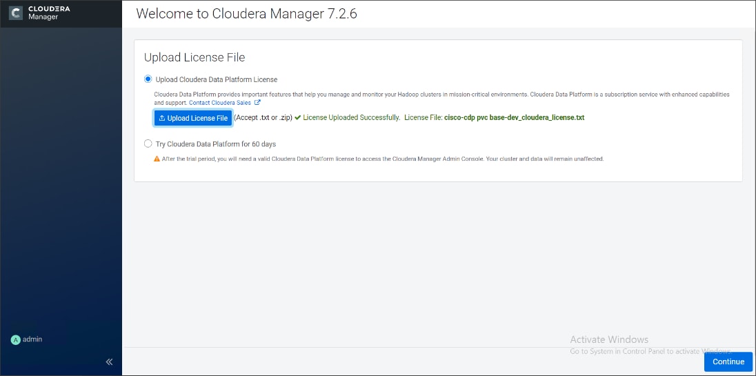
3. Click Continue on the Welcome screen.
4. Welcome screen report AutoTLS and KDC configuration pending. Follow the steps below to configuration AutoTLS and KDC.
Enable AutoTLS
Auto-TLS is managed using the certmanager utility, which is included in the Cloudera Manager Agent software, and not the Cloudera Manager Server software. You must install the Cloudera Manager Agent software on the Cloudera Manager Server host to be able to use the utility. You can use certmanager to manage auto-TLS on a new installation. For more information, go to Configuring TLS Encryption for Cloudera Manager Using Auto-TLS
1. The certmanager syntax is as follows:
/opt/cloudera/cm-agent/bin/certmanager [OPTIONS] COMMAND [ARGS]...
# export JAVA_HOME=/usr/java/jdk-11.0.9; /opt/cloudera/cm-agent/bin/certmanager setup --configure-services
2. The certificates, keystores, and password files generated by auto-TLS are stored in /var/lib/cloudera-scm-agent/agent-cert on each Cloudera Manager Agent.
# cd /var/lib/cloudera-scm-agent/agent-cert/
[root@rhelnn01 agent-cert]# ls -ll
total 12
-rw-r--r-- 1 cloudera-scm cloudera-scm 1214 Mar 4 23:50 cm-auto-global_truststore.jks
-rw------- 1 cloudera-scm cloudera-scm 4298 Mar 4 23:50 cm-auto-host_keystore.jks
3. Restart Cloudera Manager Server.
# systemctl restart cloudera-scm-server
Cloudera Manager clusters can be integrated with MIT Kerberos, Red Hat Identity Management (or the upstream FreeIPA), or Microsoft Active Directory. For more information, Enable Kerberos Authentication for CDP
![]() In our lab we configured Active-Directory based Kerberos authentication. We presume that Active Directory is pre-configured with OU, user(s) and proper authentication is setup for Kerberos Authentication.
In our lab we configured Active-Directory based Kerberos authentication. We presume that Active Directory is pre-configured with OU, user(s) and proper authentication is setup for Kerberos Authentication.
1. In Cloudera manager console select setup a KDC.
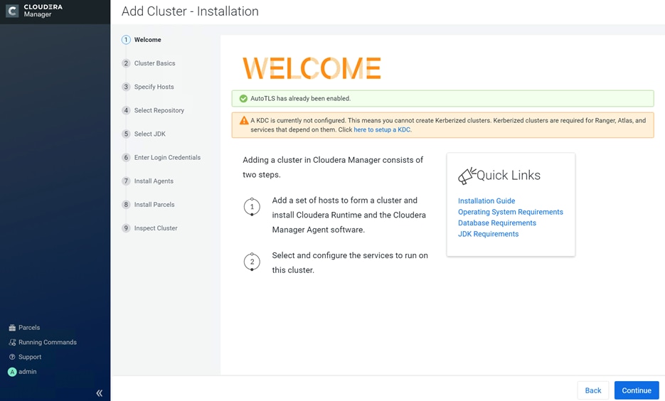
2. Select Active Directory as KDC Type.
3. Install OpenLDAP client libraries:
# ansible all -m command -a "yum install -y openldap-clients krb5-workstation krb5-libs"
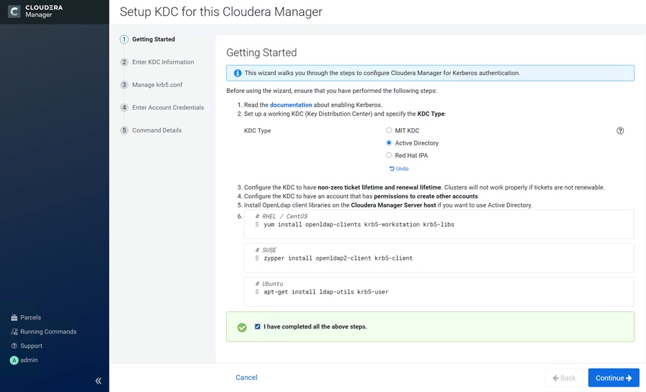
4. Enter KDC Setup details.
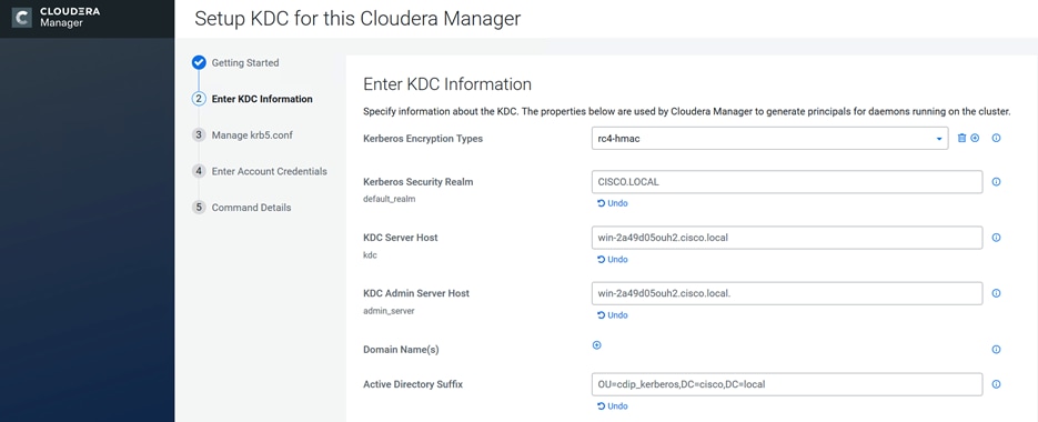
5. Check the box for Manage krb5.conf through Cloudera Manager.
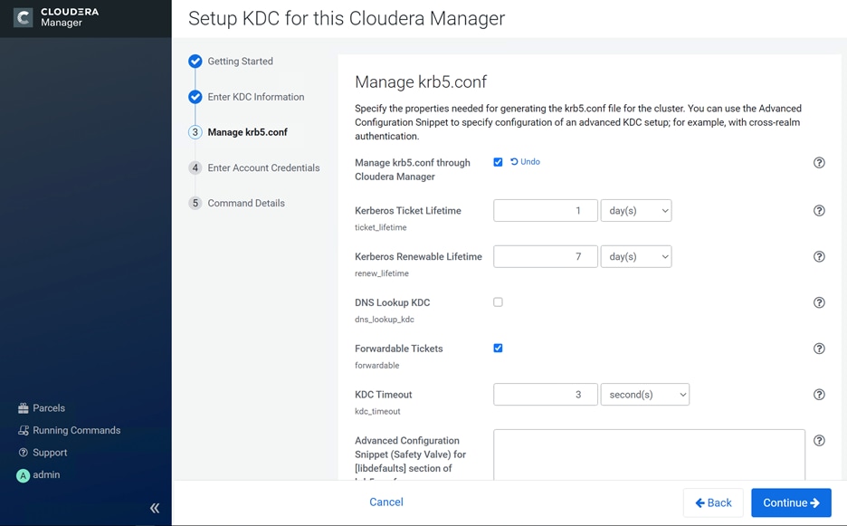
6. Enter account credentials to create other users.
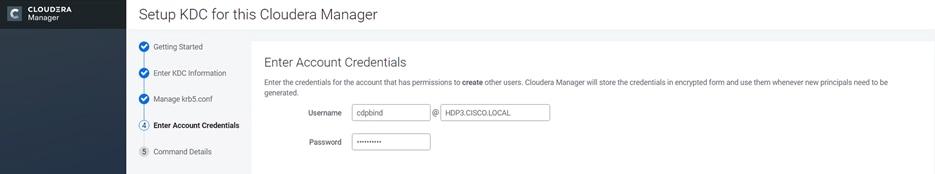
7. Click Finish.
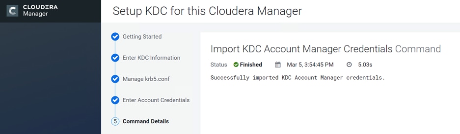
8. Sample krb5.conf created as part of the Kerberos configuration enablement.
[root@rhelnn01 ~]# cat /etc/krb5.conf
[libdefaults]
default_realm = CDIP-OZONE.CISCO.LOCAL
dns_lookup_kdc = false
dns_lookup_realm = false
ticket_lifetime = 86400
renew_lifetime = 604800
forwardable = true
default_tgs_enctypes = rc4-hmac
default_tkt_enctypes = rc4-hmac
permitted_enctypes = rc4-hmac
udp_preference_limit = 1
kdc_timeout = 3000
[realms]
CDIP-OZONE.CISCO.LOCAL = {
kdc = winjb-vlan15.cdip-ozone.cisco.local
admin_server = winjb-vlan15.cdip-ozone.cisco.local
}
[domain_realm]
The enabling Kerberos as part of the cluster configuration are shown below.
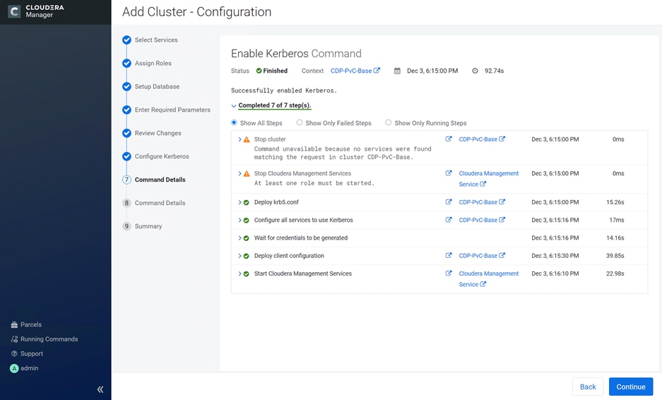
9. After the successful enablement of AutoTLS and KDC configuration, Welcome screen for Cloudera Manager reports as below:
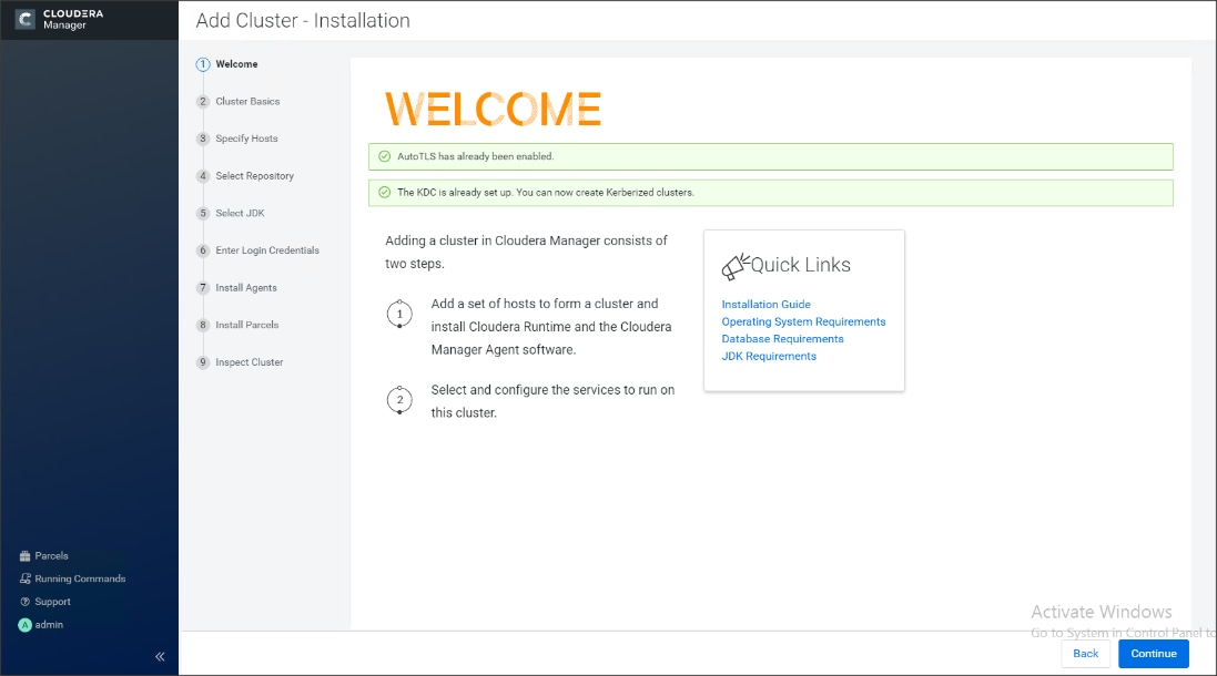
10. Enter name for the Cluster.
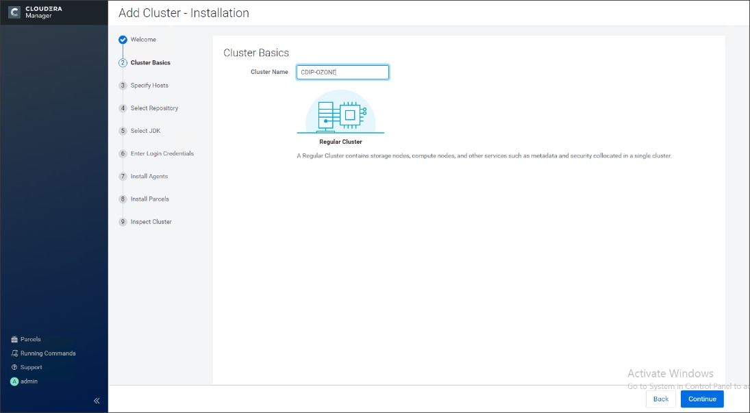
11. Specify the hosts that are part of the cluster using their IP addresses or hostname. The figure below shows a pattern that specifies the IP addresses range.
10.15.1.[101-104] or rhelnn[01-04].cdip-ozone.cisco.local
10.15.1.[105-112] or rhel[01-08].cdip-ozone.cisco.local
12. After the IP addresses or hostnames are entered, click Search.
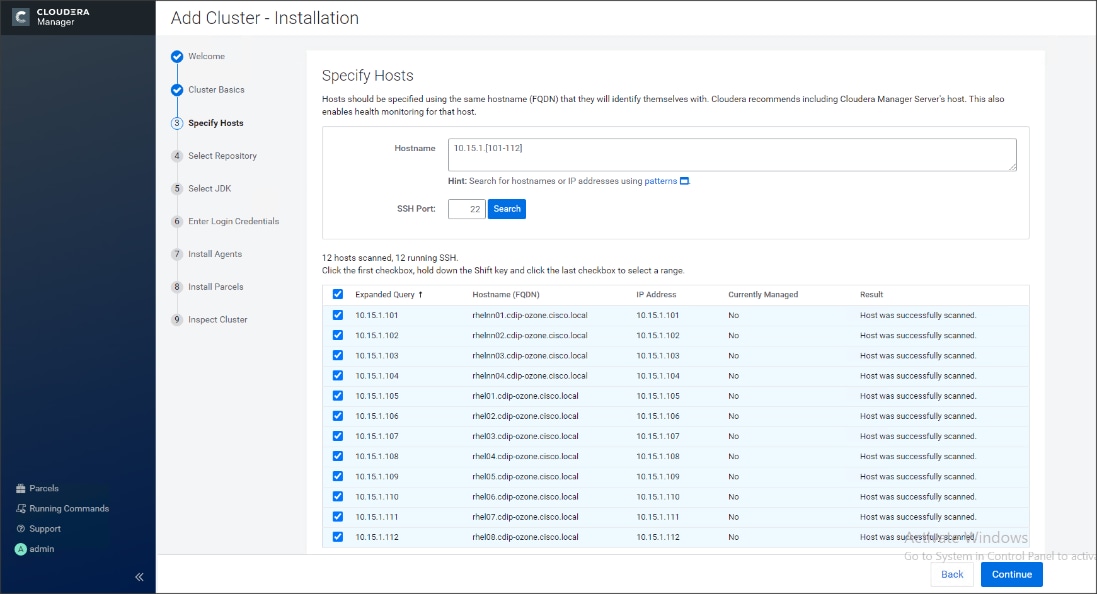
Cloudera Manager will "discover" the nodes in the cluster. Verify that all desired nodes have been found and selected for installation.
Edit the Cloudera Data Platform Private Cloud Base Parcel Settings to Use the CDP 7.1.5 Parcels
To edit the CDP PvC Base Parcel settings, follow these steps:
1. Add custom repository path for Cloudera Manager local repository created.
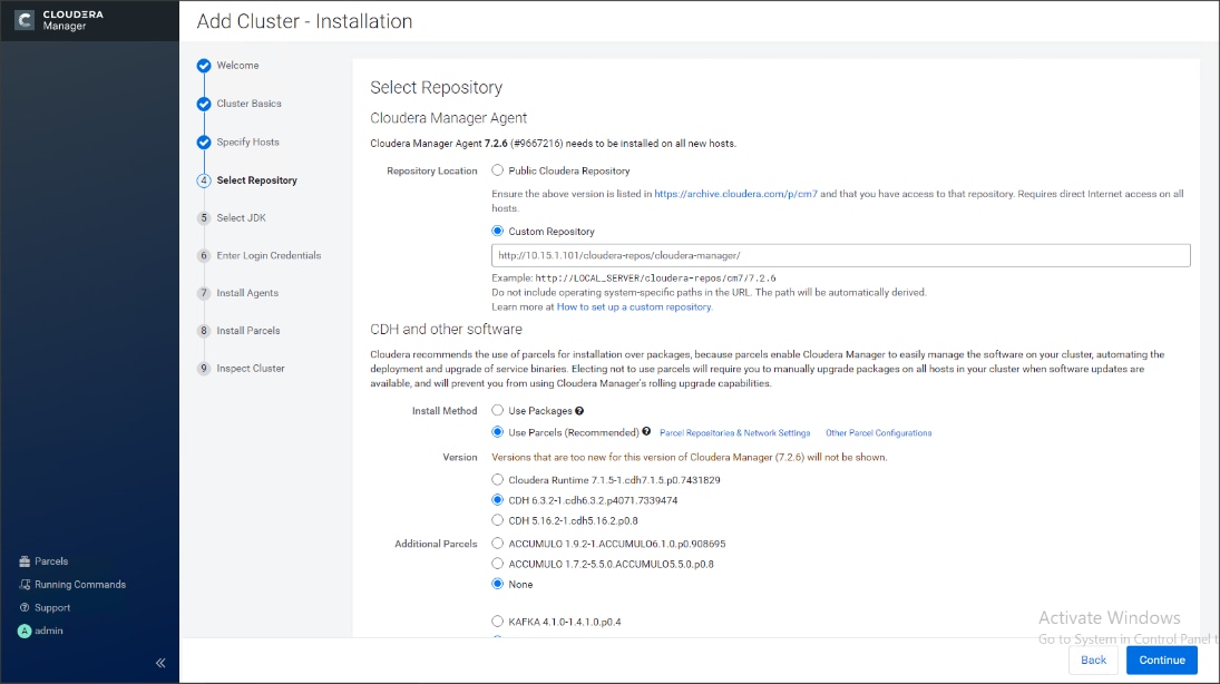
2. On the Cloudera Manager installation wizard, click Parcels.
3. Click Parcel Repositories and Network Settings.
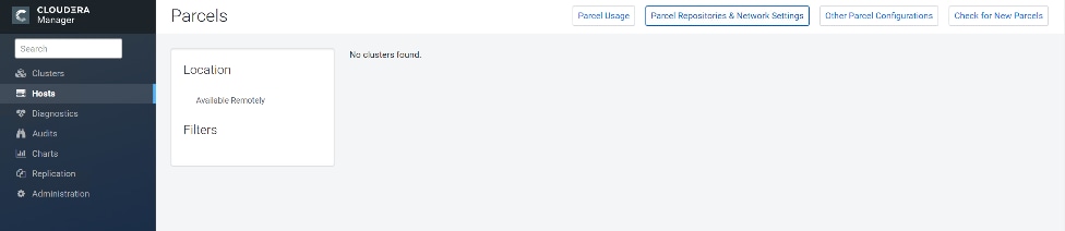
4. Click to remove the entire remote repository URLs and add the URL to the location where we kept the CDP PvC Base 7.1.5 parcels i.e. http://10.15.1.101/cloudera-repos/cdh7/7.1.5.0/parcels/CDH7.1.5.0parcels/
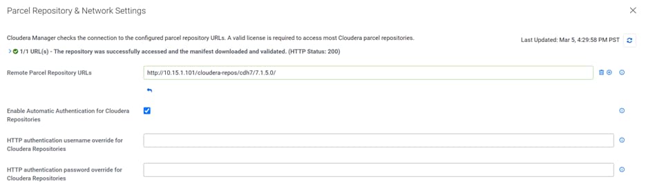
5. Click Save Changes to finish the configuration.
6. Click Continue.
7. For the method of installation, select the Use Parcels (Recommended) radio button.
8. For the CDP PvC Base 7 version, select the Cloudera Runtime 7.1.5-0.cdh7.1.5.p0.3266817 radio button.
9. For the specific release of Cloudera Manager, select the Custom Repository radio button.
10. Enter the URL for the repository within the admin node. http://10.15.1.101/cloudera-repos/cloudera-manager/ and click Continue.
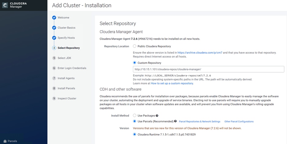
11. Select appropriate option for JDK.
![]() We selected the Manually Manager JDK option as shown below.
We selected the Manually Manager JDK option as shown below.
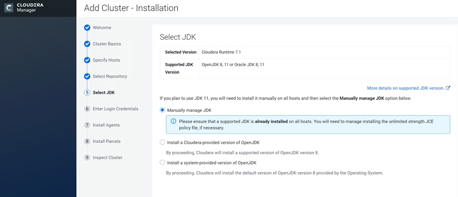
12. Provide SSH login credentials for the cluster and click Continue.
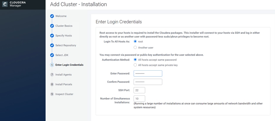
The installation of the local Cloudera repository and using parcels begins.
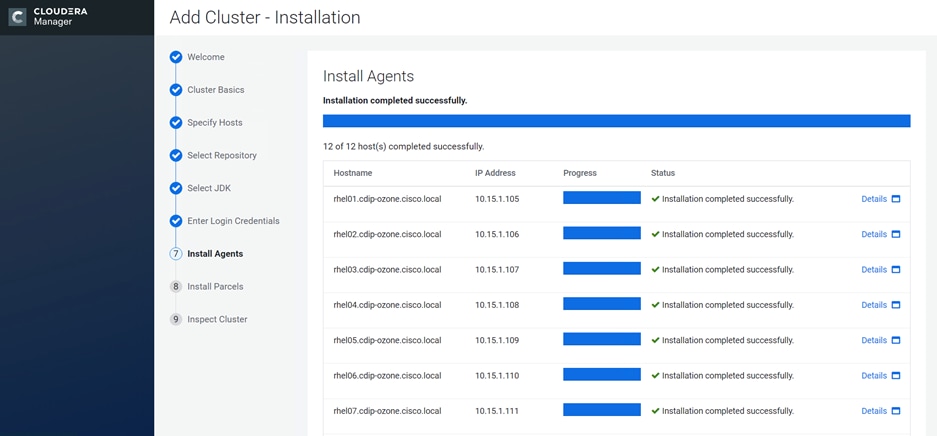
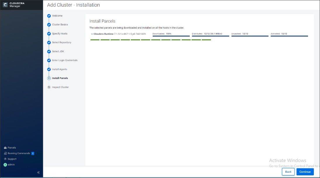
13. Run the inspect the hosts and network performance test through Cloudera Manager on which it has just performed the installation.
14. Review and verify the summary. Click Continue.
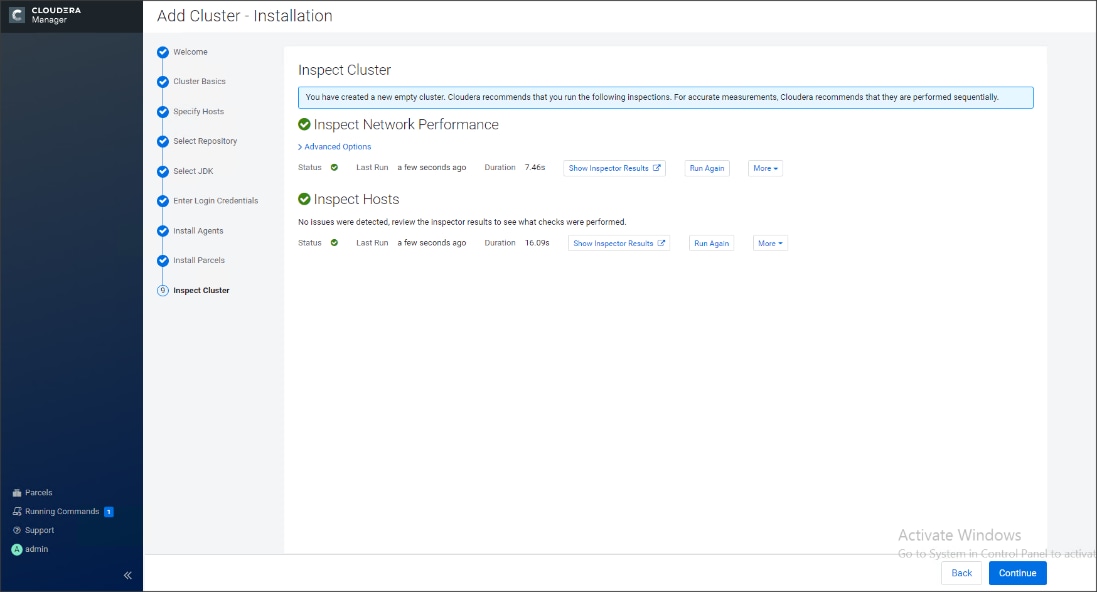
15. Select services that need to be started on the cluster.
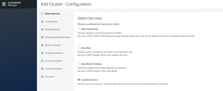
![]() We selected Custom Services for this study.
We selected Custom Services for this study.
16. This is a critical step in the installation: Inspect and customize the role assignments of all the nodes based on your requirements and click Continue.
17. Reconfigure the service assignment to match Table 8.
Table 8. Service/Role Assignment
| Service Name |
Host |
| NameNode |
rhelnn01, rhelnn02 (HA) |
| HistoryServer |
rhelnn01 |
| JournalNodes |
rhelnn01, rhelnn02, rhelnn03 |
| ResourceManager |
rhelnn02, rhelnn03 (HA) |
| Hue Server |
rhelnn02 |
| HiveMetastore Server |
rhelnn01 |
| HiveServer2 |
rhelnn02 |
| HBase Master |
rhelnn02 |
| Oozie Server |
rhelnn01 |
| ZooKeeper |
rhelnn01, rhelnn02, rhelnn03 |
| DataNode |
rhel01 to rhel16 |
| NodeManager |
rhel01 to rhel16 |
| RegionServer |
rhel01 to rhel16 |
| Sqoop Server |
rhelnn01 |
| Impala Catalog Server Daemon |
rhelnn01 |
| Impala State Store |
rhelnn02 |
| Impala Daemon |
rhel01 to rhel16 |
| Solr Server |
rhel01 (can be installed on all hosts if needed if there is a search use case) |
| Spark History Server |
rhelnn01 |
| Spark Executors |
rhel01 to rhel16 |
Figure 58. Assign Roles in Cloudera Manager; Cluster Creation Wizard Example
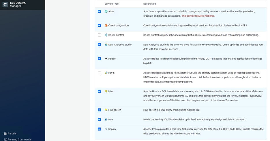
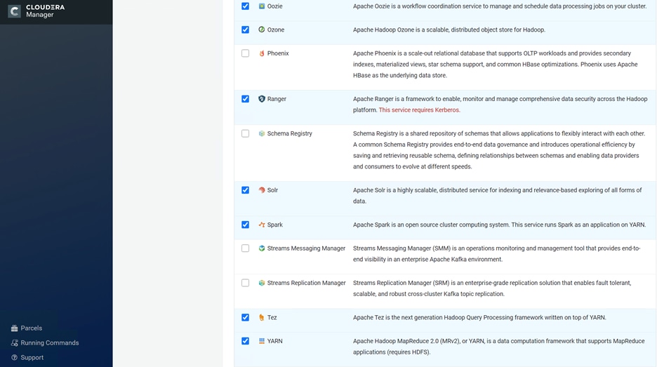
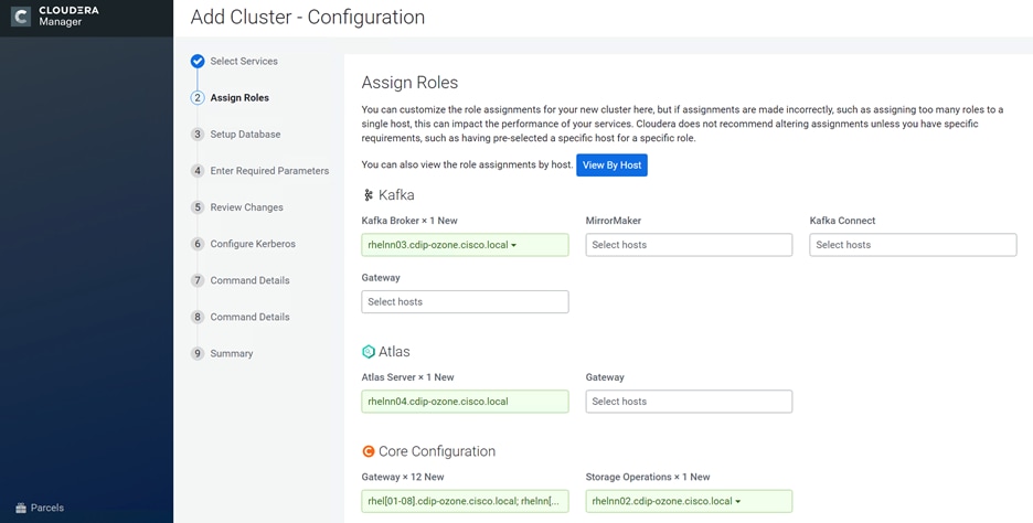
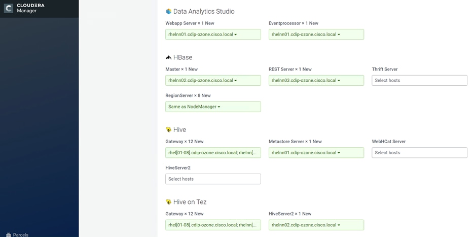
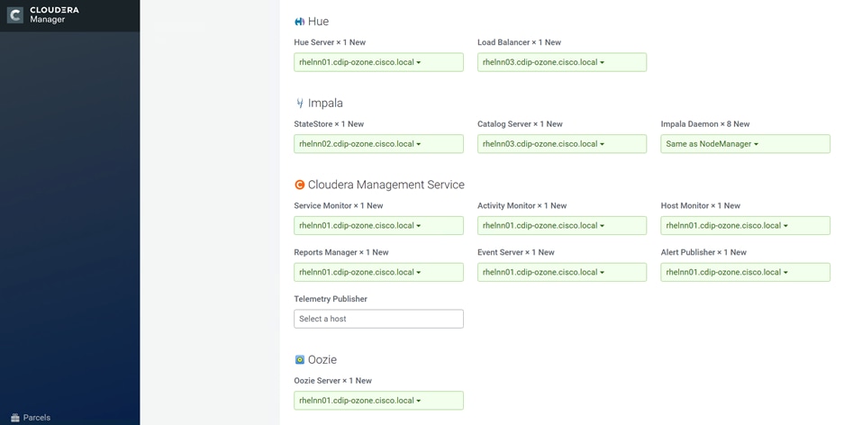
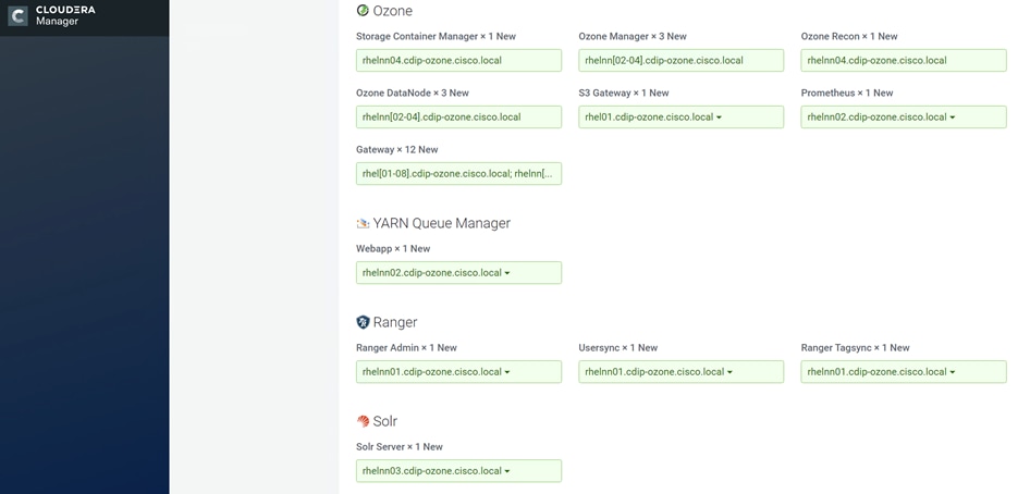
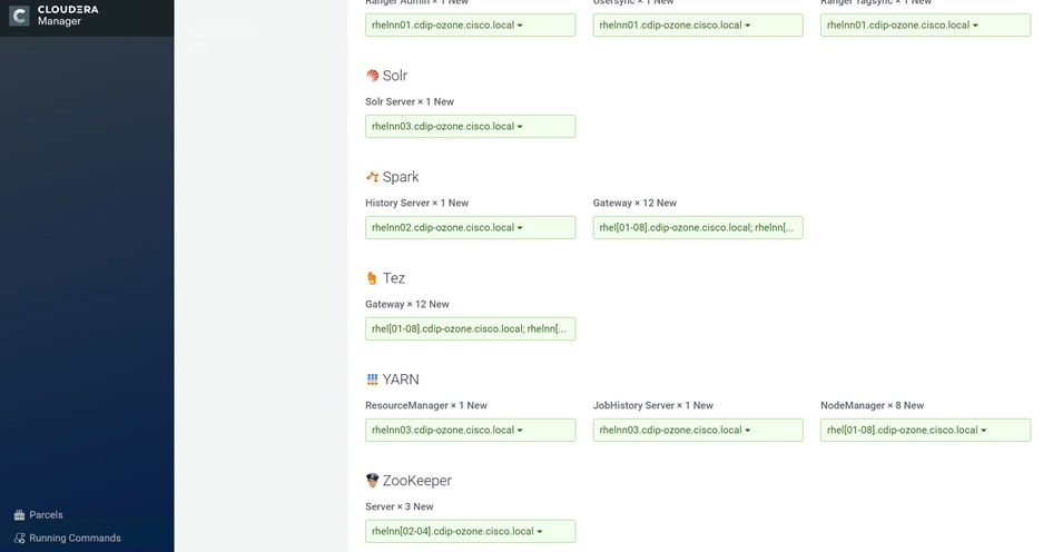
The role assignment recommendation above is for clusters of up to 64 servers. For clusters larger than 64 nodes, use the high availability recommendation defined in Table 8.
To set up the database, follow these steps:
1. In the Database Host Name sections use port 3306 for TCP/IP because connection to the remote server always uses TCP/IP.
2. Enter the Database Name, username and password that were used during the database creation stage earlier in this document.
3. Click Test Connection to verify the connection and click Continue.
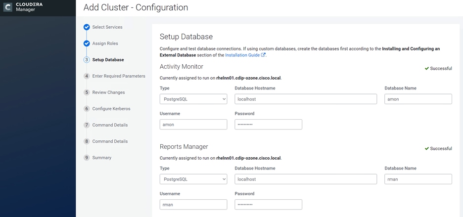
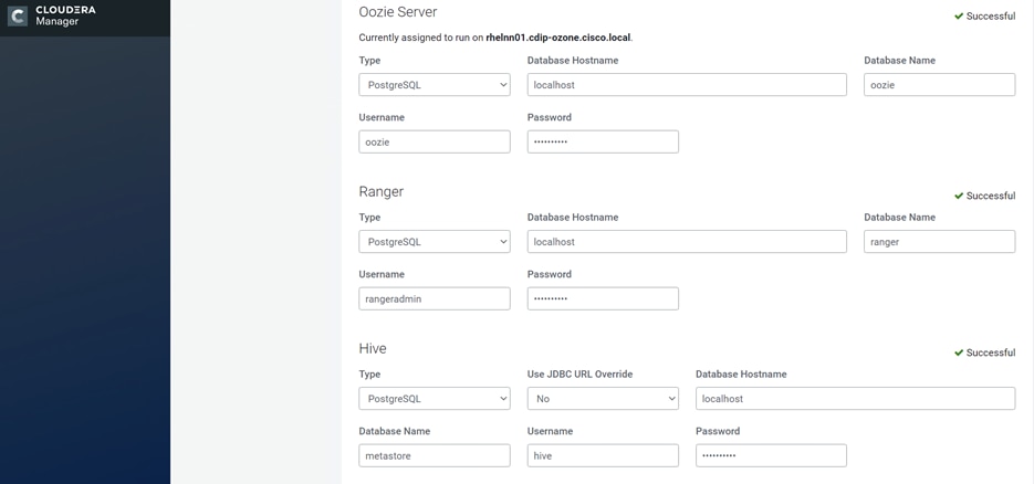
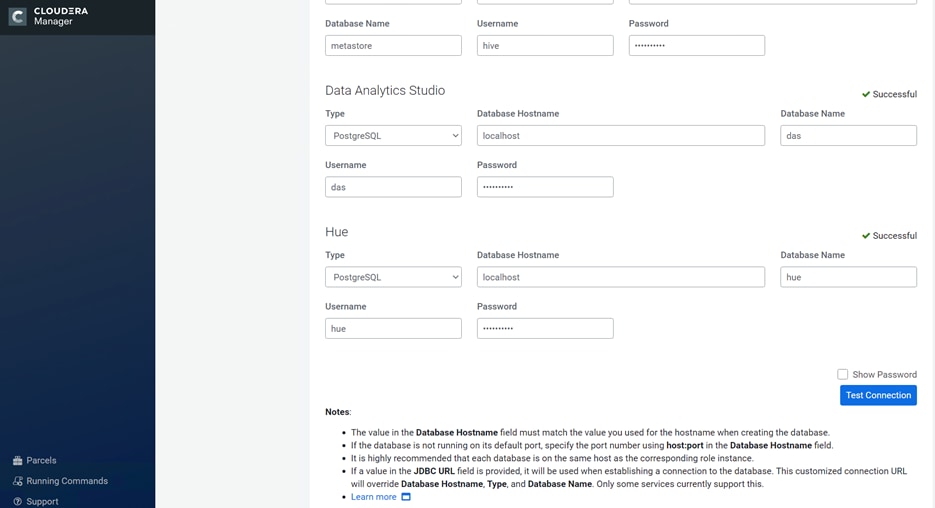
4. Enter required parameters for Data Analytics Studio.
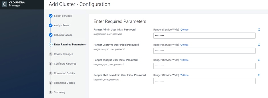
5. Review configuration, enter Ozone Service ID.
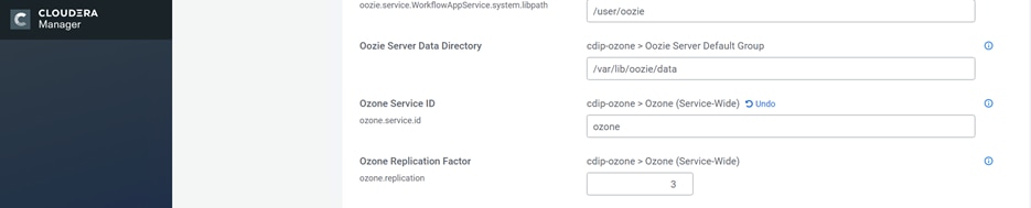
6. Configure Kerberos and Keep Review and customize the configuration changes based on your requirements.
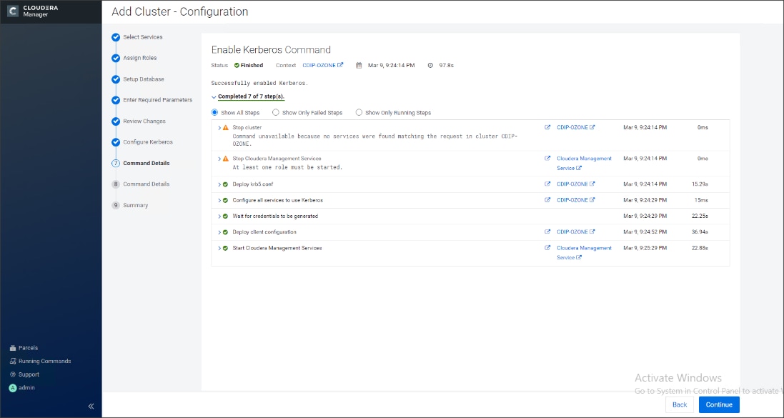
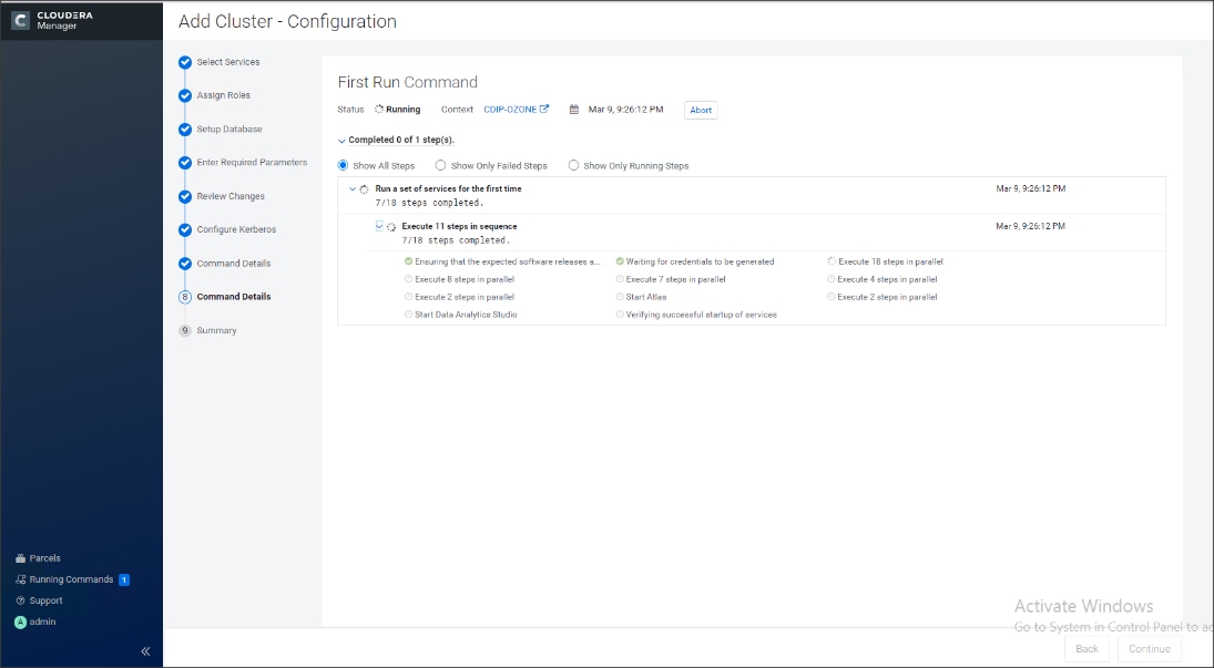
7. Click Continue to start running the cluster services.
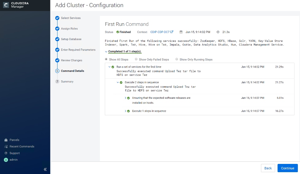
8. Hadoop services are installed, configured, and now running on all the nodes of the cluster. Click Finish to complete the installation.
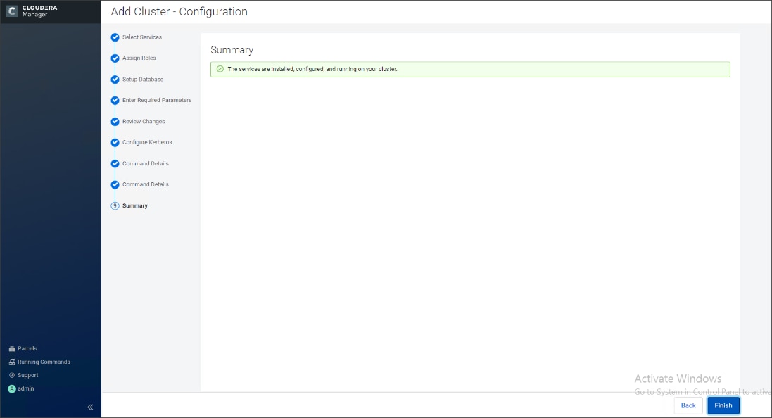
Cloudera Manager now displays the status of all Hadoop services running on the cluster.
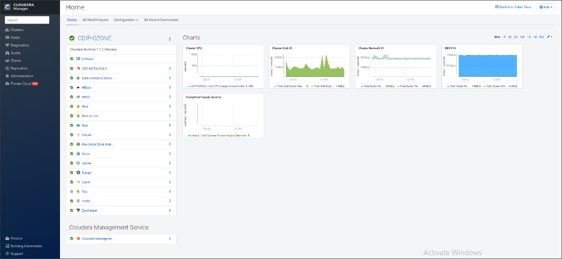
The role assignment recommendation above is for cluster with at least 64 servers and in High Availability. For smaller cluster running without High Availability the recommendation is to dedicate one server for NameNode and a second server for secondary name node and YARN Resource Manager. For larger clusters larger than 16 nodes the recommendation is to dedicate one server each for name node, YARN Resource Manager and one more for running both NameNode (High Availability) and Resource Manager (High Availability) as in the table (no Secondary NameNode when in High Availability).
![]() For production clusters, it is recommended to set up NameNode and Resource manager in High Availability mode.
For production clusters, it is recommended to set up NameNode and Resource manager in High Availability mode.
This implies that there will be at least 4 master nodes, running the NameNode, YARN Resource manager, the failover counterpart being designated to run on another node and a third node that would have similar capacity as the other two nodes.
All the three nodes will also need to run zookeeper and quorum journal node services. It is also recommended to have a minimum of 8 DataNodes in a cluster. Please refer to the next section for details on how to enable HA.
![]() Setting up High Availability is done after the Cloudera Installation is completed.
Setting up High Availability is done after the Cloudera Installation is completed.
Ozone Manager High Availability
Configuring High Availability (HA) for the Ozone Manager (OM) enables you to run redundant Ozone Managers on your Ozone cluster and prevents the occurrence of a single point of failure in the cluster from the perspective of namespace management. In addition, Ozone Manager HA ensures continued interactions with the client applications for read and write operations.
Ozone Manager HA involves a leader OM that handles read and write requests from the client applications, and at least two follower OMs, one of which can take over as the leader in situations such as the following:
● Unplanned events such as a crash involving the node that contains the leader OM.
● Planned events such as a hardware or software upgrade on the node that contains the leader OM
A High Availability (HA) configuration of the Ozone Manager (OM) involves one leader OM node and two or more follower nodes. The leader node services read and write requests from the client. The follower nodes closely keep track of the updates made by the leader so that in the event of a failure, one of the follower nodes can take over the operations of the leader
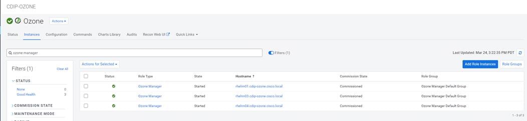
# ozone admin om getserviceroles -id=ozone
om1 : FOLLOWER (rhelnn01.cdip-ozone.cisco.local)
om2 : FOLLOWER (rhelnn03.cdip-ozone.cisco.local)
om3 : LEADER (rhelnn04.cdip-ozone.cisco.local)
![]() You cannot enable HA on a CDP cluster that already has Ozone configured. You must remove the configured Ozone service and reconfigure it with HA. Therefore, ensure that you back up your Ozone data before configuring HA. Also, ensure that there are no jobs running on the cluster before configuring HA. For more information visit, https://docs.cloudera.com/cdp-private-cloud-base/7.1.5/ozone-storing-data/topics/ozone-ha-considerations.html
You cannot enable HA on a CDP cluster that already has Ozone configured. You must remove the configured Ozone service and reconfigure it with HA. Therefore, ensure that you back up your Ozone data before configuring HA. Also, ensure that there are no jobs running on the cluster before configuring HA. For more information visit, https://docs.cloudera.com/cdp-private-cloud-base/7.1.5/ozone-storing-data/topics/ozone-ha-considerations.html
Storage Container Manager High Availability
![]() Current SCM service deployed in Apache Ozone depends on is a single point of service and has not yet implemented HA. High availability functionality for SCM has been under development and the implementation of HA solutions for SCM will be available In future CDP release.
Current SCM service deployed in Apache Ozone depends on is a single point of service and has not yet implemented HA. High availability functionality for SCM has been under development and the implementation of HA solutions for SCM will be available In future CDP release.
Recon is a centralized monitoring and management service within an Ozone cluster that provides information about the metadata maintained by different Ozone components such as the Ozone Manager (OM) and the Storage Container Manager (SCM).
Recon keeps track of the metadata as the cluster is operational and displays the relevant information through a dashboard and different views on the Recon web user interface. This information helps in understanding the overall state of the Ozone cluster.
The metadata that components such as OM and SCM maintain are quite different from one another. For example, OM maintains the mapping between keys and containers in an Ozone cluster while SCM maintains information about containers, DataNodes, and pipelines. The Recon web user interface provides a consolidated view of all these elements.
Figure 59. Example of Ozone Recon WebUI
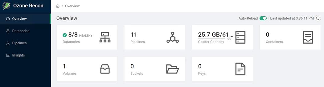
For more information, go to: https://docs.cloudera.com/cdp-private-cloud-base/7.1.5/ozone-storing-data/topics/ozone-recon-web-ui.html
Configure Ozone to Work with Prometheus
You can configure your Ozone cluster to enable Prometheus for real time monitoring of the cluster.
To enable Prometheus to work on your Ozone cluster, you must download the required binary to a specific parcel directory and use Cloudera Manager to add the Ozone Prometheus role instance.
Download the Prometheus binary from https://github.com/prometheus/prometheus/releases/tag/v2.16.0 and untar it to the following internal parcel directory on the host where you want Prometheus installed:
# /opt/cloudera/parcels/CDH/lib/hadoop-ozone/share/
Using Cloudera Manager, add the Ozone Prometheus role instance to the Ozone service.
For more information about adding role instances using Cloudera Manager, see Adding a role instance.
![]() If you do not see Ozone Prometheus in the list of role instances to configure, it means that the role instance is not configured correctly. In this situation, the Prometheus logs (/var/log/hadoop-ozone/ozone-prometheus.log) on the Prometheus instance host show a FileNotFound error.
If you do not see Ozone Prometheus in the list of role instances to configure, it means that the role instance is not configured correctly. In this situation, the Prometheus logs (/var/log/hadoop-ozone/ozone-prometheus.log) on the Prometheus instance host show a FileNotFound error.
Start the Ozone Prometheus Role Instance
For information, go to: https://docs.cloudera.com/cdp-private-cloud-base/7.1.5/ozone-storing-data/topics/ozone-prometheus-config.html
Change Ozone Metadata Directory
ozone.metadata.dirs allows Administrators to specify where the metadata must reside. Usually you pick your fastest disk (SSD if you have them on your nodes). OzoneManager, SCM and datanode will write the metadata to this path.
In the development/test environment, users configure all the metadata directory with a single location, also known as All-In-One location for simplicity. In production environments, individual services such as Ozone Manager, Storage Container Manager and Datanode can set up dedicated SSD disks for metadata on Rocks DB for best performance.
Figure 60. Change Directory Configuration on Cloudera Manager for Ozone Metadata
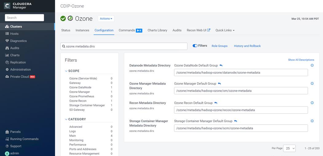
Configure Dedicated Ozone Service Metadata DB Directories
For production environments, we recommend each Ozone component to have its own metadata in RockDB stored at a dedicated location and preferably on SSD for best performance.
Figure 61. Dedicated Ozone Service Metadata DB Directories
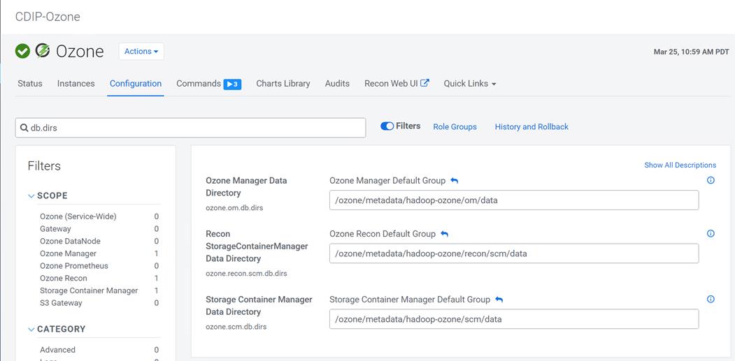
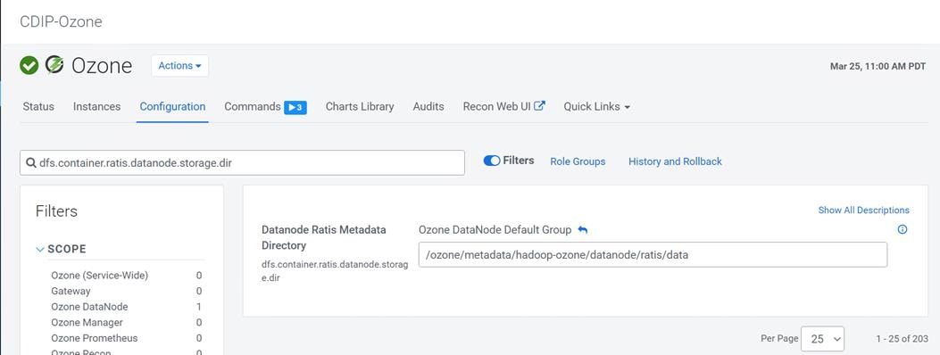
Change the Log Directory for All Applications
To change the default log from the /var prefix to /data/disk1, follow these steps:
1. Log into the cloudera home page and click My Clusters.
2. From the configuration drop-down list select All Log Directories.
3. Click Save.
To obtain a seamless operation of the application at this scale, you need the following:
● A highly scalable infrastructure with centralized management
● Deep telemetry and simplified granular troubleshooting capabilities
● Multi-tenancy for application workloads, including containers and micro-services, with the right level of security and SLA for each workload
Cisco UCS with Cisco Intersight and Cisco ACI can enable this next-generation cloud-scale architecture, deployed and managed with ease while Cloudera Data Platform Private Cloud provides the software capabilities to tie these technologies together seamlessly and securely.
For additional information, see the following resources:
● To find out more about Cisco UCS big data solutions, see http://www.cisco.com/go/bigdata.
● To find out more about Cisco Data Intelligence Platform, see https://www.cisco.com/c/dam/en/us/products/servers-unified-computing/ucs-c-series-rack-servers/solution-overview-c22-742432.pdf
● To find out more about Cisco UCS big data validated designs, see http://www.cisco.com/go/bigdata_design
● To find out more about Cisco UCS AI/ML solutions, see http://www.cisco.com/go/ai-compute
● To find out more about Cisco ACI solutions, see http://www.cisco.com/go/aci
● To find out more about Cisco validated solutions based on Software Defined Storage, see https://www.cisco.com/c/en/us/solutions/data-center-virtualization/software-defined-storage-solutions/index.html
● Cloudera Data Platform Private Cloud release note, see https://docs.cloudera.com/cdp-private-cloud/latest/release-guide/topics/cdpdc-release-notes-links.html
● CDP Private Cloud Base Requirements and Supported Versions, see https://docs.cloudera.com/cdp-private-cloud/latest/release-guide/topics/cdpdc-requirements-supported-versions.html
This section provides the BoM for the 8 240M5 Storage Server Hadoop Base Rack. See Table 9 for BOM for the Hadoop Base rack and Table 10 for Red Hat Enterprise Linux License.
Table 9. Bill of Materials for Cisco UCS C240M5SX Nodes Base Rack
| Part Number |
Description |
Qty |
| UCSC-C240-M5SX |
UCS C240 M5 24 SFF + 2 rear drives w/o CPU,mem,HD,PCIe,PS |
27 |
| CON-OSP-C240M5SX |
SNTC 24X7X4OS UCS C240 M5 24 SFF + 2 rear drives w/o CPU,mem |
27 |
| UCS-MR-X32G2RT-H |
32GB DDR4-2933-MHz RDIMM/2Rx4/1.2v |
324 |
| UCSC-RIS-1-240M5 |
Riser1 3PCIe slots(x8, x16, x8); slot3 req CPU2, For T4, RTX |
27 |
| UCSC-MLOM-C100-04 |
Cisco UCS VIC 1497 Dual Port 100G QSFP28 CNA mLOM |
27 |
| UCS-M2-960GB |
960GB SATA M.2 |
54 |
| UCS-M2-HWRAID |
Cisco Boot optimized M.2 Raid controller |
27 |
| UCSC-PSU1-1050W |
Cisco UCS 1050W AC Power Supply for Rack Server |
54 |
| CAB-N5K6A-NA |
Power Cord, 200/240V 6A North America |
54 |
| UCSC-RAILB-M4 |
Ball Bearing Rail Kit for C220 & C240 M4 & M5 rack servers |
27 |
| CIMC-LATEST |
IMC SW (Recommended) latest release for C-Series Servers. |
27 |
| UCS-SID-INFR-BD |
Big Data and Analytics Platform (Hadoop/IoT/ITOA/AI/ML) |
27 |
| UCS-SID-WKL-BD |
Big Data and Analytics (Hadoop/IoT/ITOA) |
27 |
| UCSC-HS-C240M5 |
Heat sink for UCS C240 M5 rack servers 150W CPUs & below |
54 |
| CBL-SC-MR12GM5P |
Super Cap cable for UCSC-RAID-M5HD |
27 |
| UCSC-PCIF-240M5 |
C240 M5 PCIe Riser Blanking Panel |
27 |
| UCSC-RSAS-240M5X |
C240 Rear UCS-RAID-M5HD SAS cbl(1)kitinclfan,bkpln |
27 |
| UCSC-SCAP-M5 |
Super Cap for UCSC-RAID-M5, UCSC-MRAID1GB-KIT |
27 |
| UCS-CPU-I6230R |
Intel 6230R 2.1GHz/150W 26C/35.75MB DDR4 2933MHz |
54 |
| UCSC-RAID-M5HD |
Cisco 12G Modular RAID controller with 4GB cache |
27 |
| UCS-SD38T6I1X-EV |
3.8TB 2.5 inch Enterprise Value 6G SATA SSD |
648 |
| UCS-SD19TM3X-EP |
1.9TB 2.5in Enterprise performance 6GSATA SSD(3X endurance) |
54 |
| RHEL-2S2V-3A |
Red Hat Enterprise Linux (1-2 CPU,1-2 VN); 3-Yr Support Req |
28 |
| CON-ISV1-EL2S2V3A |
ISV 24X7 RHEL Server 2Socket-OR-2Virtual; ANNUAL List Price |
28 |
| CAB-N5K6A-NA |
Power Cord, 200/240V 6A North America |
56 |
| RACK2-UCS2 |
Cisco R42612 standard rack, w/side panels |
2 |
| CON-SNT-RCK2UCS2 |
SNTC 8X5XNBD, Cisco R42612 standard rack, w side panels |
2 |
| UCS-FI-6454-U |
UCS Fabric Interconnect 6454 |
4 |
| CON-OSP-SFI6454U |
SNTC-24X7X4OS UCS Fabric Interconnect 6454 |
4 |
| UCS-PSU-6332-AC |
UCS 6332/ 6454 Power Supply/100-240VAC |
8 |
| CAB-9K12A-NA |
Power Cord, 125VAC 13A NEMA 5-15 Plug, North America |
8 |
| UCS-ACC-6332 |
UCS 6332/ 6454 Chassis Accessory Kit |
4 |
| UCS-FAN-6332 |
UCS 6332/ 6454 Fan Module |
16 |
Table 10. Red Hat Enterprise Linux License
| Part Number |
Description |
Qty |
| RHEL-2S2V-3A |
Red Hat Enterprise Linux |
27 |
| CON-ISV1-EL2S2V3A |
3-year Support for Red Hat Enterprise Linux |
27 |
![]() For Cloudera Data Platform Private Cloud Base (CDP PvC Base) software licensing requirement, contact Cloudera Data Platform software - Sales
For Cloudera Data Platform Private Cloud Base (CDP PvC Base) software licensing requirement, contact Cloudera Data Platform software - Sales
Hardik Patel, Big Data Solutions Architect, Cisco Systems, Inc.
Hardik Patel is a Technical Marketing Engineer in the Cisco UCS Product Management and Datacenter Solutions Engineering. He is currently responsible for design and development of Cisco Data Intelligence Platform architecture in collaboration with product partners. Hardik has been involved in datacenter design and deployment of compute, storage, and virtualization. Hardik holds master’s degree in computer science.
For their support and contribution to the design, validation, and creation of this Cisco Validated Design, the authors would like to thank:
● Karthik Krishna, Cisco Systems, Inc.
● Silesh Bijjahalli, Cisco Systems, Inc.
● Muhammad Afzal, Cisco Systems, Inc.
● Ali Bajwa, Cloudera
● Harsh Shah, Cloudera
● Karthik Krishnamoorthy, Cloudera
● Arpit Agarwal, Cloudera
For comments and suggestions about this guide and related guides, join the discussion on Cisco Community at https://cs.co/en-cvds.