- What's in This Guide
- Configuring Cisco Unified Communications Manager for the Cisco TelePresence System
- Configuring Cisco TelePresence Features
- Loading Cisco Options Package (COP) Files on the Cisco TelePresence System
- Verifying and Troubleshooting the Cisco TelePresence System Configuration
- Configuring and Managing the Cisco Unified IP Phone
- Satellite Licenses for the Cisco TelePresence System
- Glossary
- Index
- Contents
- Managing the Speed-Dial Directory (Favorites)
- Enabling the Directory Feature
- Configuring the BFCP over UDP Collaboration Feature
Contents
- Managing the Speed-Dial Directory (Favorites)
- Enabling the Directory Feature
- Configuring the BFCP over UDP Collaboration Feature
- T1 Support Extended Reach
- Quality Per Display - 720p (Lite)
- Self View Control
- Conference Control Protocol (CCP) VPN Security Solution
- Single Microphone Mute
- Watermark Removal
- Screen Dimming
- Installing Language Versions
- Related Information
Managing the Speed-Dial Directory (Favorites)
This section contains the following information:
- Adding Speed-Dial Numbers (Favorites) from the Unified CM Administration Page
- Adding Speed-Dial Numbers (Favorites) from the User Options Page
Adding Speed-Dial Numbers (Favorites) from the Unified CM Administration Page
To add speed-dial numbers to your Cisco TelePresence System:
Step 1 Log in to the Cisco Unified Communications Manager Administration interface.
Step 2 From the Device drop-down menu, choose Phone. The Find and List Phones Page appears.
Step 3 Enter your search criteria in the fields provided and click Find .
Step 4 Click on the phone that you want to configure with speed-dial buttons. The Phone Configuration window for that phone appears.
Step 5 Click the Related Links drop-down list box at the top right side of the window.
Step 6 Choose Add/Update Speed Dials and click Go . The Speed Dial Configuration window for this phone appears with the following configurable fields:
- Speed Dial (Button) Settings—numbers 1 through 40.
- Speed Dial (Abbreviated Dial) Settings—numbers 41 through 199. CTS does not support abbreviated dialing, so you do not need to use this field.
Step 7 Create your favorites list in these Speed Dial (Button) Settings field using the information in Table 2-1 as a guide.
Step 8 Click Save to apply your changes, then click Close to close the window.
Step 9 Click Save and then Apply Config. The phone will reboot for the changes to take effect. This will take a few minutes.

Note Do not click Reset. Doing so will cause the phone to reset and the phone could take 10 to 30 minutes to come back up.
Step 10 View your Favorites by tapping Directory and then Favorites on your Touch 12 device.
For more information about making a call using favorites, refer to the Placing and Receiving Calls chapter in the Cisco TelePresence System User Guide .
Adding Speed-Dial Numbers (Favorites) from the User Options Page
End-users can easily log in to the Cisco Personal Communications Assistant (if installed) and then choose User Options from the menu bar to navigate to User Options. When logged in and viewing User Options, you can access a User Guide, change the locale for the windows, and access additional configuration options from the Related Links drop-down list, including speed dials, phone services, and line-specific options (call forwarding, message-waiting indicators, and ring patterns).
To manage your Speed-Dials (Favorites) from User Options:
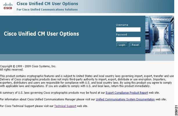
Step 1 Log in to the Cisco Unified CM User Options page, as shown in Figure 2-1.
Figure 2-1 Cisco Unified CM User Options Log In
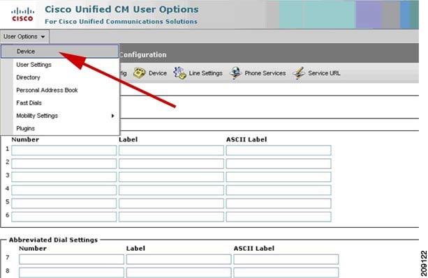
Step 2 Click User Options and select Device, as shown in Figure 2-2. The Device Configuration page appears, as shown in Figure 2-3.
Figure 2-2 User Options > Device
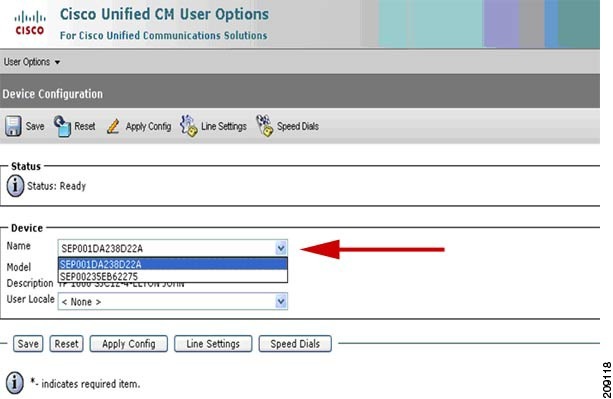
Step 3 In the Device box, click the Name drop down menu and select the phone for which you would like to create, modify, or delete speed dials, as shown in Figure 2-3. The model name will appear in the Description field, as shown in Figure 2-4.
Figure 2-3 Device Configuration
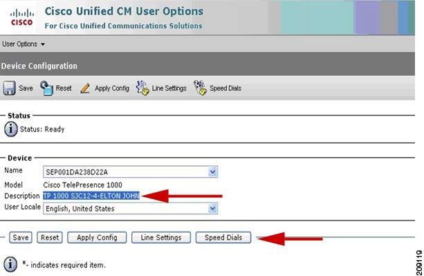
Step 5 Click Speed Dials. The Speed Dial and Abbreviated Dial Configuration page appears, as shown in Figure 2-5.
Figure 2-5 Speed Dial and Abbreviated Dial Configuration

Step 6 In the Speed Dial Settings Number field, enter the Cisco TelePresence telephone numbers (for example, 84243737). See Figure 2-5.
Step 7 In the Speed Dial Settings Label and ASCII Label fields, enter a name or friendly name. These can be a combination of letters or numbers. Hyphens and spaces are ok, but do not use any special characters (for example, % @ ! $). See Figure 2-5.
Step 8 Click Save and Apply Config when you are done. Once you save, the phone will reboot for the changes to take effect. This will take a few minutes.
Note Do not click Reset. Doing so will cause the phone to reset and the phone could take 10 to 30 minutes to come back up.
Step 9 View your Favorites by tapping Directory and then Favorites on your Touch 12 device.
For more information about making a call using favorites, refer to the Placing and Receiving Calls chapter in the Cisco TelePresence System User Guide .
Enabling the Directory Feature
The Directory button on the Cisco TelePresence Touch 12 allows a user to look up TelePresence phone numbers for co-workers. To support this feature, you must configure corporate directories. See Configuring a Corporate Directory for more information.
To set up Directory for the user from the Cisco Unified Communications Manager Administration interface:
Step 1 Log in to the Cisco Unified Communications Manager Administration interface.
Step 2 Go to System > Enterprise Parameters.
Step 3 Scroll to CCMUser Parameters.
Step 4 Locate Show Directory from the list and choose True from the drop-down menu.
This parameter determines whether or not the option Directory appears on your call control device Options web (CCMUser). If this option is enabled, the user can search directory.
Step 5 Click Save to save your settings. The change will take effect on next login to Cisco Unified Communications Manager User Options window. Default is True.
Configuring a Corporate Directory
Cisco Unified Communications Manager uses a Lightweight Directory Access Protocol (LDAP) directory to store authentication and authorization information about users of Cisco Unified Communications Manager applications that interface with Cisco Unified Communications Manager. Authentication establishes the users' rights to access the system. Authorization identifies the telephony resources that a user is permitted to use, such as a specific telephone extension.
To install and set up these features, refer to the following chapters in the Cisco Unified Communications Manager Administration Guide:
In Cisco Unified Communications Manager Administration, use the User Management > End User menu path to configure end users.
The End User Configuration window in Cisco Unified Communications Manager Administration allows the administrator to add, search, display, and maintain information about Cisco Unified Communications Manager end users. End users can control phones after you associate a phone in the End User Configuration window.
Tips About Configuring End Users
Consult the following information before you begin to configure end users:
- To verify whether the Enable Synchronizing from LDAP Server check box is checked, choose System > LDAP > LDAP System . If the check box is checked, LDAP synchronization is enabled; if not, LDAP synchronization is disabled.
- If you enable LDAP synchronization in Cisco Unified Communications Manager Administration, you thereby configure your system to use the LDAP corporate directory as the end user directory for Cisco Unified Communications Manager. In this scenario, you cannot add or delete users in Cisco Unified Communications Manager Administration. You add and remove end users in the corporate LDAP directory.
- If you enable LDAP synchronization in Cisco Unified Communications Manager Administration, you cannot change some existing user information, including user IDs, in the End User Configuration windows. Instead, you must use the corporate LDAP directory to update some user information.
- If you configure your system to authenticate users against the LDAP directory, you cannot configure or change end user passwords in Cisco Unified Communications Manager Administration. You configure and change end user passwords in the corporate LDAP directory.
After the LDAP directory configuration completes, users can use the Corporate Directory service on your Cisco Unified IP Phone 7970 Series to look up users in the corporate directory.
Cisco-Provided Default IP Phone Services
Table 2-2 displays the Cisco-provided default IP phone services that display if you specify the search parameter, IP Phone Service, and then click Find . Cisco Unified Communications Manager automatically provisions these Cisco-provided default services. To update these services, click the link in the Find and List IP Phone Service window. You can change the name of the service, where the default service displays on the phone, and the service URL. If you change the service URL for the default services, choose Both from the Service Provisioning drop-down list box, which displays in the Phone Configuration window, the Enterprise Parameter Configuration window, and the Common Phone Profile Configuration window.

Tip Some Cisco Unified IP Phone models do not support IP phone services. To determine the support for your phone model, see the Cisco Unified IP Phone Administration Guide and the Cisco Unified Communications Manager Software Compatibility Matrix on Cisco.com.
Configuring the BFCP over UDP Collaboration Feature
Binary Floor Control Protocol (BFCP) is used for controlling access to the media resources in a meeting. BFCP allows the CTS and the remote endpoint to view presentation and main display video simultaneously with improved presentation resolution for all third-party telepresence endpoints.
The CTS offers three media lines: one for audio, one for the main video, and the other for presentation or content using the session description protocol (SDP). Additionally, an application line is sent in the SDP for the BFCP control channel. The bandwidth of the presentation media line matches the capability of the CTS. For example, if the CTS is capable of 30 frames per second (fps), the presentation media line bandwidth will be 4Mbps.
The CTS uses BFCP over user datagram protocol (UDP) in both secure and non-secure BFCP modes. BFCP requires a minimum CTS Release of 1.8 and a minimum Unified CM release of 8.6(2a)SU2.
BFCP is enabled by default on all CTS endpoints beginning with CTS Release 1.8. Endpoints using CTS software prior to CTS Release 1.8 must either disable BFCP on all new SIP profiles in the Unified CM Administration interface, or upgrade all CTS endpoints to CTS Release 1.8.
Configure your system in the following order:
3. Configuring the Unified CM Trunk
Configuring the VCS Zone
Note The Cisco VCS and Unified CM must be operational before you begin.
To enable BFCP with Cisco VCS, the trunk from the Cisco VCS to Unified CM must have a custom BFCP profile configured in the Cisco Unified Communications Manager Administration interface and you must change the VCS Zone in the Cisco VCS administration interface.
For complete Cisco VCS configuration support, see the Cisco Unified Communications Manager with Cisco VCS Cisco TelePresence Deployment Guide.
To change the Zone configuration in Cisco VCS:
Step 1 Navigate to the CUCM neighbor zone VCS Configuration > Zones.
Step 2 Change the Advanced Zone profile from Cisco Unified Communications Manager to Custom.
Step 3 Set the parameters listed in Table 2-3 .
Note To use BFCP with endpoints registered to CUCM 8.6(2a)SU2 or later, select Custom for the Advanced Zone profile, configure the entries as above, then change SIP UDP/BFCP filter mode to Off.
If your system uses TLS connectivity from the Cisco VCS to Unified CM, and Cisco VCS is configured with optimal routing, either Unified CM has to trust the certificates for each Cisco VCS in the network, or you must select Custom for the Advanced Zone profile, configure the entries as above, then change Call signaling routed mode to Always. This ensures that the VCS neighbored to Unified CM will remain in the call signaling path for calls to and from Unified CM, so that Unified CM only has to trust this VCS cluster’s certificates.
Step 4 Ensure that SIP UDP/BFCP filter mode is set to Off.
For more information about the VCS, go to the Cisco TelePresence Video Communication Server (VCS) home page on Cisco.com.
Configuring BFCP For Your Cisco TelePresence Device
This section includes the steps you perform to configure BFCP and apply it to your Cisco TelePresence system and includes the following topics:
Adding a New BFCP Profile
To add a new profile for BFCP and to associate the BFCP profile to the trunk configuration on Unified CM for the trunk between VCS and CUCM, follow the steps in this section. This profile needs to be associated with every trunk and device that will use BFCP for presentation.
Step 1 Go to Device > Device Settings > SIP Profile.
Step 2 Click Add New. The SIP Profile Configuration window appears.
Step 3 Create a name for the BFCP profile. For example, “Standard BFCP SIP Profile.”
Step 4 Click to select the Allow Presentation Sharing using BFCP check box, as shown in Figure 2-6.
Figure 2-6 SIP Profile Information - Allow Presentation Sharing Using BFCP
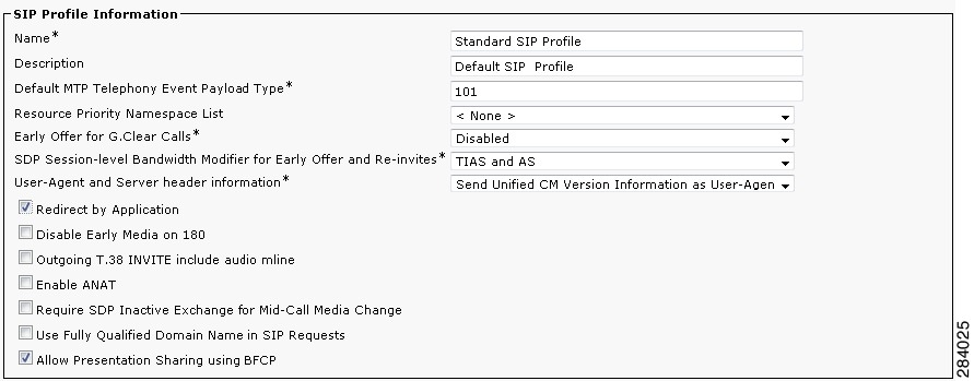
Step 5 Leave the remaining field defaults and click Apply Config and then Save.
Step 6 Configure the BFCP trunk by performing the tasks in the “Configuring the Unified CM Trunk” section.
Configuring the Unified CM Trunk
Step 2 Select the trunk for the Cisco VCS and set it to use the new BFCP profile.
Step 3 (Optional) Configure security between the Unified CM and Cisco VCS for Cisco TelePresence EX and Cisco TelePresence C Series endpoints by choosing vcs interop in the Normalization Script window (Unified CM 8.6(2a)SU2 and later releases), as shown in Figure 2-7.
Figure 2-7 Normalization Script Window - VCS Interop Security
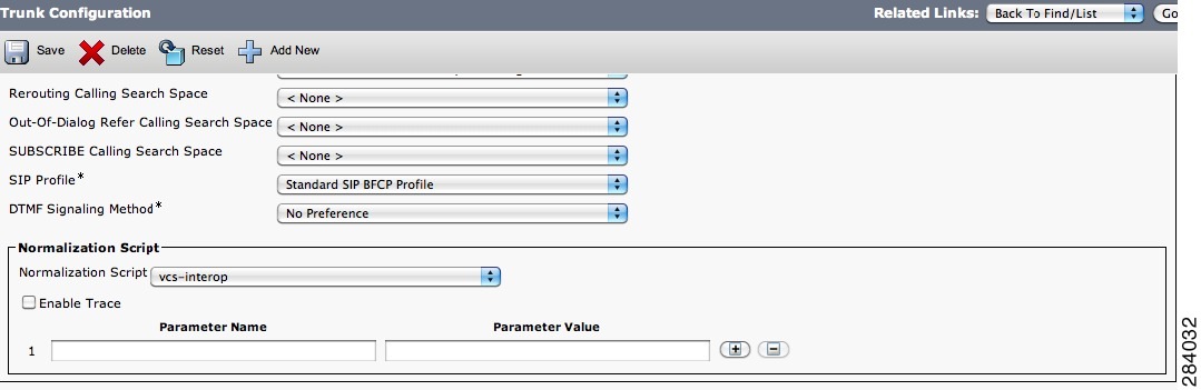
Step 4 Click Save to save your settings.
See the Cisco Unified Communications Manager with Cisco VCS Cisco TelePresence Deployment Guide for complete VCS security support information.
T1 Support Extended Reach
Note The following information applies only to single-screen systems.
The Quality per Display field in the Product Specific Configuration Layout Area window has a new setting: “High Detail, Limited Motion: 720p (Lite)” as part of the Extended Reach feature. Extended Reach users in locations where bandwidth is costly or unreliable. Because internet bandwidth is not dedicated, there may be experience issues or even call drops at certain times of the day due to a decrease in available bandwidth. Extended Reach is directly related to the quality of the call.
This feature enables the following:
- T1/E1 with QoS: 720p (Lite) and 720p (Good). See Quality Per Display - 720p (Lite). Any endpoint configured “High Detail, Limited Motion: 720p (Lite)” is in T1 mode and advertises bandwidth as appropriate.
- “Best Effort” premium broadband (Fiber-Optic Broadband Internet (FIOS), Cable).
- Sends and receives audio and video from legacy T1/E1 endpoints.
- Video output: 936Kbps.
- Presentation output: 100Kbps using 1 frame per second (FPS).
- Four jitter buffer sizes: 85ms, 125ms, 165ms, and 245ms.
- Progressive iFrames.
- Multi-point Long Term Reference Picture (LTRP) repair mechanism in H.264 codecs.
- High definition (HD) inter-operability with third-party endpoints.
- Media eXperience Engine (MXE) compatibility.
This feature disables the following:
- Audio add-in (conference) is disabled for a T1 endpoint—Only one audio or audio-video call can be made at a time.
- Backward compatibility prior to CTS Release 1.5 is not available—The endpoint displays the following message “Remote site not compatible – Contact Help Desk.”
- Standard definition (SD) interop endpoints will not see the T1 endpoint when that endpoint is detected to be the loudest endpoint speaking during a call.
Quality Per Display - 720p (Lite)
The Quality Per Display field is where you can set the bandwidth that will be used by the system. Higher bandwidth increases video quality, but may also cause packets to be dropped and video to be interrupted. The following describes expected behavior and feature limitations of the High Detail, Limited Motion: 720p (Lite) bandwidth option:
1. CTS Release 1.5.3 endpoints are not supported on an HD interop bridge; calls are dropped.
2. CTS Release 1.6.x endpoints running 720p (Lite) are supported on an HD interop bridge. All other CTS endpoints are then downgraded to 720p (Lite).
3. If a CTS Release 1.6.x endpoint running 720p (Lite) calls into a non-HD common intermediate format (CIF) interop bridge, video from legacy video endpoints will be seen on the 720p (Lite) CTS. However, video from the 720p (Lite) CTS will not be seen on the legacy endpoint. Video from other CTS endpoints in the call will be seen on both legacy and 720p (Lite) endpoints.
For configuration information, see Product Specific Configuration Layout Area.
Self View Control
The Self View feature allows you to view how you will be seen by others in a Cisco TelePresence meeting before the meeting begins. By touching the Self View softkey on your CTS Cisco Unified IP phone while the CTS is idle (not in a call), you can see a mirror image of you and your room for a specified amount of time (5 to 180 seconds), as configured in the Maximum Self View Time (in seconds) field in the Product Specific Configuration Layout Area fields for your system.
While in Self View mode, any active presentation is visible in the Presentation-in-Picture (PiP) or on the LCD display. On multi-screen systems (CTS 3000 Series and TX9000 Series), the Self View mirror image appears on all screens. On the CTS 1300, which has three cameras and a single display, the self view image is displayed from the center camera. Once you are in Self View mode, you can use the CTS Cisco Unified IP phone to select between Left, Center, and Right camera views.
Note You cannot use the Self View feature while in an active call.
See the “Product Specific Configuration Layout Area” section for information about setting the Self View time in the Maximum Self View Time (in seconds) field.
See the following sections for more information:
Shroud Lights
The lights that surround the main display screen are activated when accessing the Self View feature. When answering an incoming call in Self View mode, the lights remain on throughout the call. When you exit Self View mode, the lights remain on for a short period of time, similar to the system’s behavior at the end of a normal Cisco TelePresence call.
Answering Calls
If the CTS system is configured for Auto Answer and is in Self View mode when it receives an incoming call, the standard incoming call alert is heard and you can answer the call manually.
When a call is received while you are in Self View mode, you can exit the feature to accept the incoming video. If there is an active presentation on-screen when the call comes through, options on the CTS Cisco Unified IP phone allow you to share or hide the presentation.
Dismissing Calls
You can dismiss calls while in Self View mode without disrupting the Self View video and active presentation. Press Ignore to dismiss the call and return to the Self View page.
Pressing Ignore while in Self View mode does not divert the call. The incoming call continues to ring inaudibly until the remote end disconnects from the call. You can choose to answer the incoming call by pressing Answer, or wait until the call times out.
Note If you have voicemail configured in Unified CM, the incoming call alert is not issued because the call goes directly to voicemail.
Related Self View Feature Information
For more information about the Self View feature, refer to the Cisco TelePresence System User Guide that corresponds with your system’s software release.
Conference Control Protocol (CCP) VPN Security Solution
This feature allows an administrative domain that is hosting a Business-to-Business (B2B) conference to configure its Cisco TelePresence Multipoint Switch (CTMS) using a specific URL structure. This URL structure allows the CCP HTTP traffic of participating CTS endpoints to be routed hop by hop across one or more service provider (SP) HTTP proxies to reach the correct CTMS.
In the CCP VPN model (fixed path) solution, the Administrator configures the enterprise by adding a static (fixed path) configuration file to the Cisco Unified Communications Manager (Unified CM). When the CTS joins a CTMS meeting, it attempts to route CCP traffic based on this configuration file. All CCP HTTP traffic then attempts to go to the local CTMS. If no local CTMS matches, packet traffic is routed to the HTTP proxy.
You can verify configuration status by checking the system status messages for your system and by checking the configuration using command-line interface (CLI) commands. When configuration is complete, the Meeting Control button is active on the CTS Cisco Unified IP phone.
Note This feature is only active if the enterprise configuration file on the Cisco Unified Communications Manager TFTP server is configured. If there is no TFTP configuration file present on the system, conference control uses the Internet model (free path).
This feature cannot be configured while in an active Cisco TelePresence call.
Single Microphone Mute
On systems with multiple microphones, you can mute individual microphones by pressing and holding the Mute button for three seconds until the green LED light turns off. That microphone is now muted (no muted Microphone icon displays on the main screen). To unmute the locally muted microphone, press the Mute button once. The green LED light turns on and the microphone is active again (or muted if the room is already muted).
Note Global room muting is still available by pressing the Mute button once on any table microphone.
This feature is supported on Gen 2 and all TX series devices. To check if you are running a Gen 2 device, enter the following command:
Once you have verified that you are running a Gen 2 device, go to the Cisco Unified Communications Manager Administration interface and check the Enable Single Microphone Mute box at the bottom of the device Product Specific Configuration Layout window. This feature is disabled by default.
Single microphone mute is supported in Unified CM firmware release 8.5.1 and later releases.
Watermark Removal
Broadcast customers who want to remove the Cisco logo from their video presentations when it interferes with on-screen elements can do so in the Unified CM Administration interface by downloading a Broadcast license.
Step 1 Request a Broadcast license from your Cisco account representative.
Your license arrives in separate emails.
Step 2 Rename the license .txt file to SEPxxxxxxxxxxxx.lic (where xxx is the MAC address in all caps).
Note Be sure to keep the .lic extension in lower case.
Step 3 Upload your newly named file to the Unified CM TFTP directory and restart the TFTP.
Step 4 Restart you TelePresence system by logging in to the TelePresence system and entering the utils system restart command at the admin prompt.
Step 5 Once your broadcast license is loaded, log in as admin to check your license status using command-line interface (CLI).
Step 6 At the admin prompt enter show license status. The license status shows that it is disabled. For example:
Step 7 At the admin prompt enter set license broadcast enable.
Step 8 Reboot the system by entering the utils system restart command at the admin prompt.
Your Broadcast license is now installed and enabled.
Screen Dimming
To save power and extend the lifespan of the Cisco TelePresence Touch 12 device, the Touch 12 will dim between the hours specified in the User Preferences Area in Unified CM. For more information, see the “User Preferences Area” section.
When dimming is active, the screen is dimmed and the home button is glowing. If the Touch 12 or one of its hard buttons is touched, the device will turn back on. The device will stay on until the system has been idle for one hour. At that time, the screen will dim again.
The screen will not dim during the specified hours when the system is in a call, recording or troubleshooting. The screen will automatically wake up when an incoming call or pop-up notification appears, or when an upgrade begins.
Installing Language Versions
Note This feature is only supported on systems that use the Touch 12 device for call control, and that use software release 1.10.0 or 6.0.0 or later.
Unified CM enables you to configure devices for a specific locale, language and country. This configuration alters the text and date/time formats of the user interface (UI), as well as tones.
In order to change the UI language and tones, you must install the appropriate locale packs. These packs allow you to view and receive the chosen translated text or ringtones on your Touch 12 device.
Cisco provides a locale pack file bundle on cisco.com that 14 languages other than English. Table 2-4 contains a list of these available languages.


Understanding Locale Pack File Types and Naming Conventions
There are two types of locale files: locale installers for Unified CM and locale packs for CTS and TX systems.
Locale installer files are installed to Unified CM. They must be installed before the locale packs are installed. The locale installer files on Unified CM enable the CTS or TX system and the Touch 12 device to install and use the locale packs properly.
Note Cisco highly recommends that you install both the Combined Network locale installer and the locale installer for your preferred language and country. The Combined Network locale installer contains country-specific files for various network items, including ringtones, annunciators and gateway tones.
Locale installer files use the following naming conventions:
cm-locale-UnifiedCMLocaleCode-M.m.a.p-b.cop.sgn
UnifiedCMLocaleCode = the five-character locale identifier expressed as ll_RR or combined_network
– ll = the language, such as es (Spanish) or zh (Chinese).
– RR = the specific region to which the language is targeted, such as ES (Spanish - Spain) or TW (Chinese - Taiwan).
a = Maintenance release number
Each locale pack contains language information for a specific language and country. When installed to the CTS or TX system, the locale pack changes the language of the Touch 12 device.
The locale pack file bundle for CTS uses the following naming conventions:
po-locale-ctsmain_combo-M.m.a.p-b.cop.sgn
Installing Locale Installers for the Unified CM Server
Prior to installing the locale files to your system, you must download the locale installer for both the Combined Network and your country of preference. To install your locale installer, complete the following steps:
Step 2 Navigate to Support > All Downloads.
Step 3 Navigate to Products > Voice and Unified Communications > IP Telephony > Unified Communications Platform > Cisco Unified Communications Manager (CallManager) > Cisco Unified Communications Manager Version {your version number}.
Step 4 Click the link that says Unified Communications Manager/CallManager Locale Installer.
Step 5 Download the locale installer (*.cop.sgn file) for the Combined Network.
Step 6 Download the locale installer (*.cop.sgn file) for your language and country of choice . See Table 2-4 for a list of the Unified CM locale codes that correspond with each language and country.
Step 7 Copy the files to a TFTP server that is accessible by Unified CM.
Step 8 Log in to Unified CM and upload the locale installers to the Unified CM Server. See “Installing the Cisco TelePresence COP File to the Unified CM Server” section (Step 13 through Step 23) for instructions.
Note If the upgrade file is located on a Linux or Unix server, you must enter a forward slash at the beginning of the directory path. For example, if the upgrade file is in the "patches" directory, you must enter "/patches". If the upgrade file is located on a Windows server, check with your system administrator for the correct directory path.
Installing Locale Packs for the CTS or TX System and Touch 12 Device
Note The process to install the COP files used for locale packs on to Unified CM for Cisco TelePresence Systems is the same process as that used to install COP files for Cisco Unified IP Phones. For more information about COP files, refer to Chapter 3, “Loading Cisco Options Package (COP) Files on the Cisco TelePresence System”.
To install your locale pack, complete the following steps:
Step 2 Navigate to Support > All Downloads > Products > TelePresence > TelePresence Endpoints - Immersive > your TelePresence series > your TelePresence system.
Step 3 Download the locale pack file bundle: Cisco TelePresence Language Pack for CTS500-32, CTS1300-47, TX1310-65, TX9000, TX9200 (*.cop.sgn file).
Step 4 Copy the file bundle to a TFTP server that is accessible by Unified CM.
Step 5 Log in to Unified CM and upload the file bundle to the Unified CM server. See “Installing the Cisco TelePresence COP File to the Unified CM Server” section (Step 13 through Step 23) for instructions.
Step 6 Restart the TFTP server to activate the newly-installed locale packs.
Note Do not restart the TFTP server until you have installed the locale packs on all servers in the cluster.
Step 7 Continue to the “Configuring User Interface Language, Ringtones and Date and Time” section.
Configuring User Interface Language, Ringtones and Date and Time
After you upload the file to Unified CM and restart the TFTP server, complete the following steps to apply your preferred language settings:
Step 1 Log in to Cisco Unified CM Administration .
Step 2 Navigate to System > Device Pool (to change device dates and time settings).
Note For more information on how to set up a device pool, or how to set up your date and time format, refer to the Device Pool Setup and Date and Time Group Setup chapters of the Cisco Unified Communications Manager Administration Guide.
Step 3 Navigate to Device > Phone .
Step 4 Search for your device and click on the hyperlink under Device Name to select it.
Step 5 Navigate to Device Information to change the device language and ringtones.
- Change the User Locale field to your language and country of preference. To find the Unified CM User Locale Value that corresponds with your language, see Table 2-4 . Changing this field changes the language on the Touch 12 device. Onscreen messages also change on the following systems: CTS 500-32, CTS 1300-47, TX 1310-65, and TX 9x00 series.
Note The User Locale value that you select must correspond with the locale pack you installed. See Table 2-4 for the CTS locale codes. If you select <None>, the Touch 12 language will default to English, United States.
Step 6 Click Save, then click OK when prompted.
Step 7 Click Apply Config, then click OK when prompted.
Note If you upgrade your system to the newest software release, you must download and install the locale packs whose numbering matches your new software. For example, if you upgraded from TX 6.0.0 to 6.0.1, you would need to download both the 6.0.1 TX files and the locale pack file bundle for 6.0.1.
 Feedback