Catalyst 4948E and Catalyst 4948E-F Switch Installation Guide
Bias-Free Language
The documentation set for this product strives to use bias-free language. For the purposes of this documentation set, bias-free is defined as language that does not imply discrimination based on age, disability, gender, racial identity, ethnic identity, sexual orientation, socioeconomic status, and intersectionality. Exceptions may be present in the documentation due to language that is hardcoded in the user interfaces of the product software, language used based on RFP documentation, or language that is used by a referenced third-party product. Learn more about how Cisco is using Inclusive Language.
- Updated:
- January 4, 2012
Chapter: Power Supply Specifications
Power Supply Specifications
This appendix provides the specifications for the AC-input and DC-input power supplies supported on the Catalyst 4948E switch.

Tip ![]() For additional information about the Cisco Catalyst 4948E and the Catalyst 4948E-F switches (including configuration examples and troubleshooting information), see the documents listed on this page:
For additional information about the Cisco Catalyst 4948E and the Catalyst 4948E-F switches (including configuration examples and troubleshooting information), see the documents listed on this page:
http://www.cisco.com/en/US/products/ps6021/tsd_products_support_series_home.html
300 W AC-Input Power Supply (PWR-C49E-300AC-R)
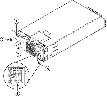
The PWR-C49E-300AC-R 300 W AC-input power supply can be installed only in the Catalyst 4948E switch chassis. This power supply is not supported on the Catalyst 4948E-F switch. Figure A-1 shows the 300 W AC-input power supply with the major features identified.
Figure A-1 AC-Input Power Supply (PWR-C49E-300AC-R) Features
|
|
AC power switch |
|
Power supply LEDs |
|
|
Captive installation screw |
|
Power supply handle |
|
|
AC power cord receptacle |
Table A-1 lists the specifications for the 300 W AC-input power supply (PWR-C49E-300AC-R).
|
|
|
|---|---|
AC-input type |
• • |
AC-input voltage |
• • |
AC-input current |
• • |
AC-input frequency |
47 to 63 Hz |
Branch circuit requirements |
Each chassis power supply should have its own dedicated, fused-branch circuit: • • • – – |
Power supply output |
25 A @+12 VDC |
Output holdup time |
20 ms minimum |
kVA rating1 |
0.375 kVA |
Power supply fan |
• • • |
Power supply LEDs |
|
INPUT OK |
• • – – • |
OUTPUT OK |
• • – – – • |
Weight |
2 lb (0.9 kg) |
1 The kVA rating listed for the power supply should be used as the sizing criteria for both UPS outputs as well as standard circuits and transformers to power a switch. |
300 W AC-Input Power Supply (PWR-C49E-300AC-F)
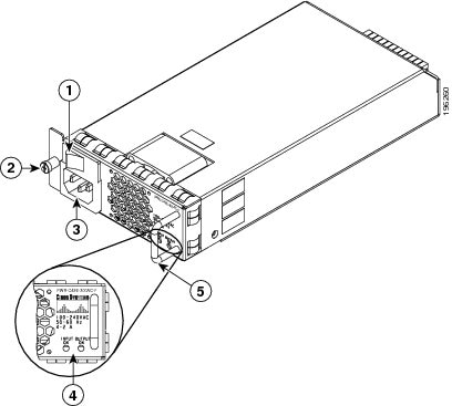
The PWR-C49E-300AC-F 300 W AC-input power supply can be installed only in the Catalyst 4948E-F switch chassis. This power supply is not supported on the Catalyst 4948E switch. Figure A-2 shows the 300 W AC-input power supply with the major features identified.
Figure A-2 AC-Input Power Supply (PWR-C49E-300AC-F) Features
|
|
AC power switch |
|
Power supply LEDs |
|
|
Captive installation screw |
|
Power supply handle |
|
|
AC power cord receptacle |
Table A-1 lists the specifications for the 300 W AC-input power supply (PWR-C49E-300AC-F).
|
|
|
|---|---|
AC-input type |
• • |
AC-input voltage |
• • |
AC-input current |
• • |
AC-input frequency |
47 to 63 Hz |
Branch circuit requirements |
Each chassis power supply should have its own dedicated, fused-branch circuit: • • • – – |
Power supply output |
25 A @+12 VDC |
Output holdup time |
20 ms minimum |
kVA rating1 |
0.4 kVA |
Power supply fan |
• • • |
Power supply LEDs |
|
INPUT OK |
• • – – • |
OUTPUT OK |
• • – – – • |
Weight |
2 lb (0.9 kg) |
1 The kVA rating listed for the power supply should be used as the sizing criteria for both UPS outputs as well as standard circuits and transformers to power a switch. |
300 W AC-Input Power Supply Power Cords
Table A-5 lists the specifications for the AC power cords that are available for both of the 300 W AC-input power supplies. The table includes references to illustrations of the AC power cords.

Note ![]() All 300 W AC-input power supply power cords have an IEC60320/C15 appliance plug at one end. This plug connects to the AC-in receptacle on the power supply faceplate.
All 300 W AC-input power supply power cords have an IEC60320/C15 appliance plug at one end. This plug connects to the AC-in receptacle on the power supply faceplate.
|
|
|
|
|
|
|---|---|---|---|---|
Argentina |
CAB-IR2073-C15-AR= (was CAB-7KACR=) |
IRAM 2073 |
10 A, 250 VAC |
|
Australia, New Zealand |
CAB-AS3112-C15-AU= (was CAB-7KACA=) |
SAA AS 3112 |
10 A, 250 VAC |
|
Continental Europe |
CAB-CEE77-C15-EU= (was CAB-7KACE=) |
CEE 7/7 |
10 A, 250 VAC |
|
Italy |
CAB-C2316-C15-IT= (was CAB-7KACI=) |
CEI 23-16/7 |
10 A, 250 VAC |
|
North America, Japan |
CAB-US515-C15-US= (was CAB-7KAC=) |
NEMA 5-151 |
13 A, 125 VAC |
|
North America |
CAB-N5K6A-NA= |
NEMA 6-15P |
10 A, 250 VAC |
|
South Africa, India |
CAB-SABS-C15-IND= |
BS 546 |
10 A, 250 VAC |
|
Switzerland |
CAB-9K10A-SW= (was CAB-7KACSW=) |
SEV 1011 |
10 A, 250 VAC |
|
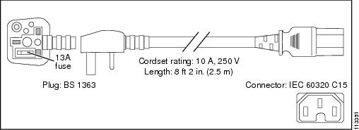
United Kingdom |
CAB-BS1363-C15-UK= (was CAB-7KACU=) |
BS 13632 |
13 A, 250 VAC |
1 For Japan, ask your local electrical contractor to prepare the NEMA 5-20 power plug. 2 Plug contains a 13 A fuse. |
Figure A-3 CAB-IR2073-C15-AR=, CAB-7KACR= (Argentina)
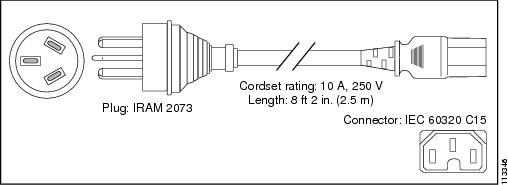
Figure A-4 CAB-AS3112-C15-AU=, CAB-7KACA= (Australia and New Zealand)
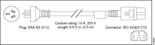
Figure A-5 CAB-CEE77-C15-EU=, CAB-7KACE= (Continental Europe)
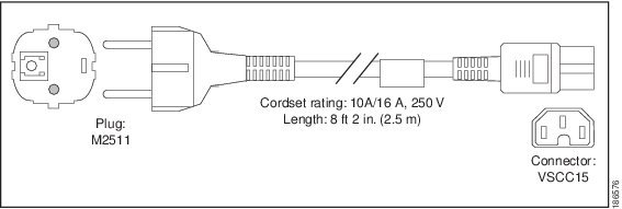
Figure A-6 CAB-C2316-C15-IT=, CAB-7KACI= (Italy)
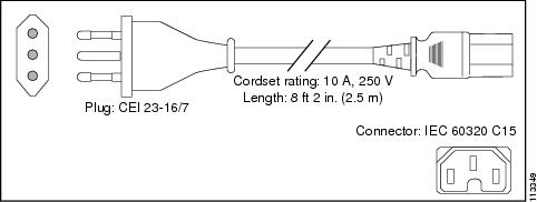
Figure A-7 CAB-US515-C15-US=, CAB-7KAC= (North America)
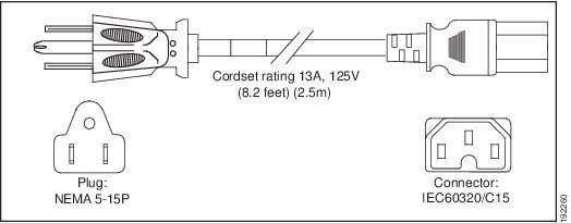
Figure A-8 CAB-N5K6A-NA (North America)
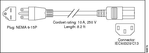
Figure A-9 CAB-SABS-C15-IND (South Africa, India)
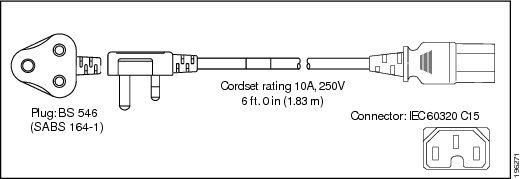
Figure A-10 CAB-9K10A-SW=, CAB-7KACSW= (Switzerland)
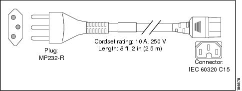
Figure A-11 CAB-BS1363-C15-UK=, CAB-7KACU= (United Kingdom)
300 W DC-Input Power Supply (PWR-C49-300DC)
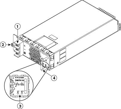
Figure A-12 shows the 300 W DC-input power supply with the major features identified. The PWR-C49-300DC DC-input power supply is supported only on the Catalyst 4948E switch chassis.
Figure A-12 300 W DC-Input Power Supply (PWR-C49-300DC)
|
|
Source DC terminal block |
|
Power supply LEDs |
|
|
Captive installation screw |
|
Power supply handle |
Table A-6 lists the specifications for the 300 W DC-input power supply (PWR-C49-300DC).
|
|
|
|---|---|
DC-input voltage |
• • |
DC-input current |
Nominal range is 6.66 A to 8.33 A |
Power supply output capacity |
300 W |
Power supply output |
25 A @ 12 VDC |
Output holdup time |
8 ms (minimum) |
Heat dissipation |
341 BTU/hour (power supply only) |
Power supply LEDs |
|
INPUT OK |
• • – – • |
OUTPUT OK |
• • – – – • |
Power supply fan |
• • • |
Weight |
2 lb (0.9 kg) |
 Feedback