Catalyst 4948E and Catalyst 4948E-F Switch Installation Guide
Bias-Free Language
The documentation set for this product strives to use bias-free language. For the purposes of this documentation set, bias-free is defined as language that does not imply discrimination based on age, disability, gender, racial identity, ethnic identity, sexual orientation, socioeconomic status, and intersectionality. Exceptions may be present in the documentation due to language that is hardcoded in the user interfaces of the product software, language used based on RFP documentation, or language that is used by a referenced third-party product. Learn more about how Cisco is using Inclusive Language.
- Updated:
- January 4, 2012
Chapter: Removal and Replacement Procedures
Removal and Replacement Procedures
This chapter describes how to perform the following removal and replacement procedures for the Catalyst 4948E and the Catalyst 4948E-F switch field-replaceable units (FRUs) and contains these sections:
•![]() Removing and Installing the DC-Input Power Supply
Removing and Installing the DC-Input Power Supply
•![]() Removing and Installing the AC-Input Power Supply
Removing and Installing the AC-Input Power Supply
•![]() Removing and Installing the Fan Tray
Removing and Installing the Fan Tray
 |
Warning |

Tip ![]() For additional information about the Cisco Catalyst 4948E switch (including configuration examples and troubleshooting information), see the documents listed on this page:
For additional information about the Cisco Catalyst 4948E switch (including configuration examples and troubleshooting information), see the documents listed on this page:
http://www.cisco.com/en/US/products/ps6021/tsd_products_support_series_home.html
The chassis FRUs and their associated part numbers are listed in Table 4-1.
Removing and Installing the DC-Input Power Supply
This section describes how to remove and install the DC-input power supplies (PWR-C49-300DC) in the Catalyst 4948E switch chassis and contains these subsections:
•![]() Removing the DC-Input Power Supply
Removing the DC-Input Power Supply
•![]() Installing the DC-Input Power Supply
Installing the DC-Input Power Supply

Note ![]() The Catalyst 4948E-F chassis does not support the PWR-C49-300DC DC-input power supply.
The Catalyst 4948E-F chassis does not support the PWR-C49-300DC DC-input power supply.

Note ![]() You can use the grounding lug to attach a wrist strap for ESD protection during servicing.
You can use the grounding lug to attach a wrist strap for ESD protection during servicing.
|
Warning |
Required Tools
To perform this procedure, you will need a Number 2 Phillips screwdriver.
Removing the DC-Input Power Supply
To remove a DC-input power supply, follow these steps:
Step 1 ![]() Set the power switch/circuit breaker to the off (0) position on the circuit that feeds the power supply that you are removing.
Set the power switch/circuit breaker to the off (0) position on the circuit that feeds the power supply that you are removing.
As an added precaution, place the appropriate safety flag and lockout devices at the source power circuit breaker, or place a piece of adhesive tape over the circuit breaker handle to prevent accidental power restoration while you are working on the circuit.
Step 2 ![]() Remove the clear plastic terminal block cover from the power supply terminal block.
Remove the clear plastic terminal block cover from the power supply terminal block.
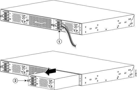
Step 3 ![]() Disconnect the DC-input cables from the power supply terminal block in this order (See Figure 4-1, top view):
Disconnect the DC-input cables from the power supply terminal block in this order (See Figure 4-1, top view):
1. ![]() Positive (+) source DC cable from the positive (+) terminal
Positive (+) source DC cable from the positive (+) terminal
2. ![]() Negative (-) source DC cable from the negative (-) terminal
Negative (-) source DC cable from the negative (-) terminal
3. ![]() Ground cable from the ground terminal
Ground cable from the ground terminal
Step 4 ![]() Loosen the captive installation screw on the power supply.
Loosen the captive installation screw on the power supply.
Step 5 ![]() Grasp the power supply handle with one hand, and slide the power supply halfway out of the chassis. Place your other hand underneath the power supply, as shown in Figure 4-1 (bottom view), and slide the power supply completely out of the chassis. Set the power supply aside.
Grasp the power supply handle with one hand, and slide the power supply halfway out of the chassis. Place your other hand underneath the power supply, as shown in Figure 4-1 (bottom view), and slide the power supply completely out of the chassis. Set the power supply aside.
Note ![]() The DC power supply is equipped with an EMI gasket on the top and bottom (on the front edge) of the power supply. When sliding the power supply into or out of the power supply bay, be careful not to damage the EMI gaskets.
The DC power supply is equipped with an EMI gasket on the top and bottom (on the front edge) of the power supply. When sliding the power supply into or out of the power supply bay, be careful not to damage the EMI gaskets.
Step 6 ![]() If the power supply bay is to remain empty, install a blank faceplate (WS-X4994) over the opening, and secure it in place with the captive installation screw.
If the power supply bay is to remain empty, install a blank faceplate (WS-X4994) over the opening, and secure it in place with the captive installation screw.
Figure 4-1 Removing the DC-Input Power Supply
|
|
Detach the power leads from the terminal block in the following order: • • • |
|
Loosen captive installation screw |
Installing the DC-Input Power Supply
|
Warning |
To install a DC-input power supply in the Catalyst 4948E switch, follow these steps:
Step 1 ![]() Ensure that the system (earth) ground chassis connection has been made.
Ensure that the system (earth) ground chassis connection has been made.
Step 2 ![]() Verify that power is off to the DC circuit that feeds the power supply that you are installing.
Verify that power is off to the DC circuit that feeds the power supply that you are installing.
As an added precaution, place the appropriate safety flag and lockout devices at the source power circuit breaker, or place a piece of adhesive tape over the circuit breaker handle to prevent accidental power restoration while you are working on the circuit.
Step 3 ![]() Remove the new DC-input power supply from its protective packaging.
Remove the new DC-input power supply from its protective packaging.
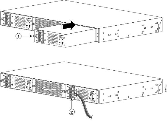
Step 4 ![]() Grasp the power supply handle with one hand, and place your other hand underneath the power supply. Slide the power supply into the power supply bay until the power supply makes contact with the chassis power connector. (See Figure 4-2.) Press firmly on the power supply faceplate to fully seat the power supply in the bay.
Grasp the power supply handle with one hand, and place your other hand underneath the power supply. Slide the power supply into the power supply bay until the power supply makes contact with the chassis power connector. (See Figure 4-2.) Press firmly on the power supply faceplate to fully seat the power supply in the bay.
Note ![]() The DC power supply is equipped with an EMI gasket on the top, bottom, and sides (on the front edge) of the power supply. When sliding the power supply into the power supply bay, be careful not to damage the EMI gaskets.
The DC power supply is equipped with an EMI gasket on the top, bottom, and sides (on the front edge) of the power supply. When sliding the power supply into the power supply bay, be careful not to damage the EMI gaskets.
Step 5 ![]() Tighten the power supply captive installation screw.
Tighten the power supply captive installation screw.
Step 6 ![]() Remove the plastic cover from the terminal block.
Remove the plastic cover from the terminal block.
Step 7 ![]() Attach the appropriate lugs to the source DC wires.
Attach the appropriate lugs to the source DC wires.
Either insulated crimp-on spade lugs or insulated crimp-on ring connectors can be used on the source DC cables. They should be sized according to local and national installation requirements and electrical codes.
Note ![]() The wire should be sized according to local and national installation requirements and electrical codes. Use only copper wire.
The wire should be sized according to local and national installation requirements and electrical codes. Use only copper wire.
Step 8 ![]() Connect the DC-input wires to the terminal block in this order:
Connect the DC-input wires to the terminal block in this order:
1. ![]() Ground cable to the ground connector on the terminal block
Ground cable to the ground connector on the terminal block
2. ![]() Negative (-) source DC cable to the negative (-) connector on the terminal block
Negative (-) source DC cable to the negative (-) connector on the terminal block
3. ![]() Positive (+) source DC cable to the positive (+) connector on the terminal block
Positive (+) source DC cable to the positive (+) connector on the terminal block
Step 9 ![]() After ensuring that all wire connections are secure, reinstall the plastic terminal block cover.
After ensuring that all wire connections are secure, reinstall the plastic terminal block cover.
Note ![]() In a system with dual power supplies, connect each power supply to a separate power source. In case of a power source failure to one supply, the second power source should still be available.
In a system with dual power supplies, connect each power supply to a separate power source. In case of a power source failure to one supply, the second power source should still be available.
Step 10 ![]() Remove any safety flag and lockout devices or any tape from the circuit breaker switch handle, and restore power by moving the circuit breaker switch handle to the on (|) position.
Remove any safety flag and lockout devices or any tape from the circuit breaker switch handle, and restore power by moving the circuit breaker switch handle to the on (|) position.
Step 11 ![]() Verify the power supply operation by ensuring that the INPUT OK and the OUTPUT OK LEDs on the power supply front panel are both green.
Verify the power supply operation by ensuring that the INPUT OK and the OUTPUT OK LEDs on the power supply front panel are both green.
Figure 4-2 Installing the DC-Input Power Supply
|
|
Secure the power supply in the chassis with the captive installation screw. |
|
Attach the source DC leads to the terminal block in the following order: • • • |
Removing and Installing the AC-Input Power Supply
This section describes how to remove and install the AC-input power supply (PWR-C49E-300AC-R) in the Catalyst 4948E switch chassis or the AC-input power supply (PWR-C49E-300AC-F) in the Catalyst 4948E-F switch chassis and contains the following subsections:
•![]() Removing the AC-Input Power Supply
Removing the AC-Input Power Supply
•![]() Installing the AC-Input Power Supply
Installing the AC-Input Power Supply
Note ![]() The two models of AC-input power supplies are not interchangeable between the two chassis. They are keyed to prevent accidental insertion into the wrong chassis.
The two models of AC-input power supplies are not interchangeable between the two chassis. They are keyed to prevent accidental insertion into the wrong chassis.
Required Tools
You might need a Number 2 Phillips screwdriver to loosen or tighten the captive installation screw.
Removing the AC-Input Power Supply
Note ![]() If you have a Catalyst 4948E-F switch chassis and you have also installed the optional Panduit ToR Switch Inlet Duct (model CDE2) to extend the chassis's air intake, you do not need to remove the air duct or the switch chassis in order to remove and replace the AC-input power supply. There is adequate working space within the air duct to perform the removal and replacement steps.
If you have a Catalyst 4948E-F switch chassis and you have also installed the optional Panduit ToR Switch Inlet Duct (model CDE2) to extend the chassis's air intake, you do not need to remove the air duct or the switch chassis in order to remove and replace the AC-input power supply. There is adequate working space within the air duct to perform the removal and replacement steps.
To remove the AC-input power supply from the chassis, follow these steps:
Step 1 ![]() Set the power switch to the off (0) position on the power supply that you are removing.
Set the power switch to the off (0) position on the power supply that you are removing.
Step 2 ![]() Disconnect the AC power cord from source AC and from the AC-in connector on the power supply. Set the power cord aside.
Disconnect the AC power cord from source AC and from the AC-in connector on the power supply. Set the power cord aside.
Step 3 ![]() Loosen the captive installation screw on the power supply.
Loosen the captive installation screw on the power supply.
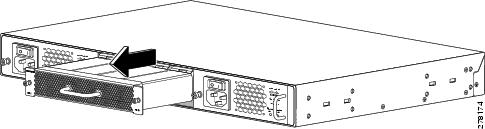
Step 4 ![]() Grasp the power supply handle with one hand, and slide the power supply halfway out of the chassis. Place your other hand underneath the power supply and slide the power supply completely out of the chassis. (See Figure 4-3.) Set the power supply aside.
Grasp the power supply handle with one hand, and slide the power supply halfway out of the chassis. Place your other hand underneath the power supply and slide the power supply completely out of the chassis. (See Figure 4-3.) Set the power supply aside.
Note ![]() The AC power supply is equipped with an EMI gasket on the top, bottom, and sides (on the front edge) of the power supply. When sliding the power supply into or out of the power supply bay, be careful not to damage the EMI gaskets.
The AC power supply is equipped with an EMI gasket on the top, bottom, and sides (on the front edge) of the power supply. When sliding the power supply into or out of the power supply bay, be careful not to damage the EMI gaskets.
Step 5 ![]() If the power supply bay is to remain empty, install a blank faceplate (WS-X4994= for the Catalyst 4948E or WS-X4994-F= for the Catalyst 4948E-F) over the opening, and secure it in place with the captive installation screw.
If the power supply bay is to remain empty, install a blank faceplate (WS-X4994= for the Catalyst 4948E or WS-X4994-F= for the Catalyst 4948E-F) over the opening, and secure it in place with the captive installation screw.
Figure 4-3 Removing and Installing an AC-Input Power Supply

Installing the AC-Input Power Supply
Note ![]() If you have a Catalyst 4948E-F switch chassis and you have also installed the optional Panduit ToR Switch Inlet Duct (model CDE2) to extend the chassis's air intake, you do not need to remove the air duct or the switch chassis in order to remove and replace the AC-input power supply. There is adequate working space within the air duct to perform the removal and replacement steps.
If you have a Catalyst 4948E-F switch chassis and you have also installed the optional Panduit ToR Switch Inlet Duct (model CDE2) to extend the chassis's air intake, you do not need to remove the air duct or the switch chassis in order to remove and replace the AC-input power supply. There is adequate working space within the air duct to perform the removal and replacement steps.
To install an AC-input power supply in the chassis, follow these steps:
Step 1 ![]() Remove the new AC-input power supply from its protective packaging and set the packaging aside.
Remove the new AC-input power supply from its protective packaging and set the packaging aside.
Step 2 ![]() Loosen the two captive installation screws and remove the blank faceplate (WS-X4994= for the Catalyst 4948E or WS-X4994-F= for the Catalyst 4948E-F) covering the empty power supply bay opening. Save the blank faceplate for possible future use.
Loosen the two captive installation screws and remove the blank faceplate (WS-X4994= for the Catalyst 4948E or WS-X4994-F= for the Catalyst 4948E-F) covering the empty power supply bay opening. Save the blank faceplate for possible future use.
Step 3 ![]() Verify that the power switch is in the off (0) position on the power supply that you are installing.
Verify that the power switch is in the off (0) position on the power supply that you are installing.
Note ![]() If the power supply is connected to source AC with the power on/off switch in the on position, the two LEDs on the power supply faceplate will be lit red. To clear this condition, cycle the power on/off switch off, then on. The LEDs should then be lit green.
If the power supply is connected to source AC with the power on/off switch in the on position, the two LEDs on the power supply faceplate will be lit red. To clear this condition, cycle the power on/off switch off, then on. The LEDs should then be lit green.
Step 4 ![]() Grasp the power supply handle with one hand, and place your other hand underneath the power supply. Slide the power supply into the power supply bay. Make sure that the power supply is fully seated in the power supply bay.
Grasp the power supply handle with one hand, and place your other hand underneath the power supply. Slide the power supply into the power supply bay. Make sure that the power supply is fully seated in the power supply bay.
Note ![]() The AC power supply is equipped with an EMI gasket on the top and the bottom front edge of the power supply. When sliding the power supply into the power supply bay, be careful not to damage the EMI gaskets.
The AC power supply is equipped with an EMI gasket on the top and the bottom front edge of the power supply. When sliding the power supply into the power supply bay, be careful not to damage the EMI gaskets.
Step 5 ![]() Tighten the power supply captive installation screw.
Tighten the power supply captive installation screw.
Step 6 ![]() Plug the AC power cord appliance connector (C15 or C13 connector) into the AC-in receptacle on the power supply.
Plug the AC power cord appliance connector (C15 or C13 connector) into the AC-in receptacle on the power supply.
Step 7 ![]() Plug the other end of the AC power cord into the source AC outlet.
Plug the other end of the AC power cord into the source AC outlet.
Step 8 ![]() Switch the power supply on/off switch to on.
Switch the power supply on/off switch to on.
Verify the power supply operation by ensuring that the corresponding power supply LED (PS1 or PS2) on the chassis front panel is lit green. Also check the LEDs on the power supply front panel. Both LEDs (INPUT OK and OUTPUT OK) should be lit green.
As an added check, verify that you can hear the power supply fan operating.
Removing and Installing the Fan Tray
This section describes how to remove and install the system fan tray (WS-X4993=) in the Catalyst 4948E switch chassis and contains these subsections:
Required Tools
You might need a flat-blade or Number 2 Phillips screwdriver to loosen or tighten the captive installation screw on the fan tray.
Removing the Fan Tray
The system fan tray (WS-X4993=) can be removed and replaced while the system is operating without presenting an electrical hazard to the user or damage to the system. A 30-second window is provided for you to remove the defective fan tray and install the replacement tray. If you exceed 30 seconds, the system starts to overheat and automatically shuts down.
Note ![]() If you have a Catalyst 4948E-F switch chassis and you have also installed the optional Panduit ToR Switch Inlet Duct (model CDE2) to extend the chassis's air intake, you do not need to remove the air duct or the switch chassis in order to remove and replace the fan tray. There is adequate working space within the air duct to perform the removal and replacement steps.
If you have a Catalyst 4948E-F switch chassis and you have also installed the optional Panduit ToR Switch Inlet Duct (model CDE2) to extend the chassis's air intake, you do not need to remove the air duct or the switch chassis in order to remove and replace the fan tray. There is adequate working space within the air duct to perform the removal and replacement steps.
|
Warning |
To remove the installed fan assembly, follow these steps:
Step 1 ![]() Remove the replacement fan tray from its shipping packaging and place it near the chassis that you are working on.
Remove the replacement fan tray from its shipping packaging and place it near the chassis that you are working on.
Step 2 ![]() Loosen the two captive installation screws on the installed fan tray.
Loosen the two captive installation screws on the installed fan tray.
Step 3 ![]() Grasp the fan assembly handle, and pull it outward; gently move the fan tray from side to side, if necessary, to unseat the fan tray power connector from the chassis connector. (See Figure 4-4.)
Grasp the fan assembly handle, and pull it outward; gently move the fan tray from side to side, if necessary, to unseat the fan tray power connector from the chassis connector. (See Figure 4-4.)
Step 4 ![]() Place your free hand under the fan tray to support it. Pull the fan assembly clear of the chassis, and set it aside. (See Figure 4-4.)
Place your free hand under the fan tray to support it. Pull the fan assembly clear of the chassis, and set it aside. (See Figure 4-4.)
Figure 4-4 Removing and Installing the Fan Tray
Installing the Fan Tray
Note ![]() You have 30 seconds to install the replacement fan tray before the system automatically shuts down.
You have 30 seconds to install the replacement fan tray before the system automatically shuts down.
To install the new fan tray, follow these steps:
Step 1 ![]() Position the replacement fan tray in front of the fan tray bay at the rear of the chassis. (See Figure 4-4.)
Position the replacement fan tray in front of the fan tray bay at the rear of the chassis. (See Figure 4-4.)
Step 2 ![]() Slide the fan tray into the fan tray bay until the power connector seats in the chassis fan connector and the captive installation screws make contact with the chassis. The fans should immediately power up.
Slide the fan tray into the fan tray bay until the power connector seats in the chassis fan connector and the captive installation screws make contact with the chassis. The fans should immediately power up.
Step 3 ![]() Tighten the two fan tray captive installation screws to secure the fan tray in the chassis.
Tighten the two fan tray captive installation screws to secure the fan tray in the chassis.
Step 4 ![]() Verify that the FAN LED on the chassis front panel is lit green.
Verify that the FAN LED on the chassis front panel is lit green.
 Feedback