Catalyst 4948E and Catalyst 4948E-F Switch Installation Guide
Bias-Free Language
The documentation set for this product strives to use bias-free language. For the purposes of this documentation set, bias-free is defined as language that does not imply discrimination based on age, disability, gender, racial identity, ethnic identity, sexual orientation, socioeconomic status, and intersectionality. Exceptions may be present in the documentation due to language that is hardcoded in the user interfaces of the product software, language used based on RFP documentation, or language that is used by a referenced third-party product. Learn more about how Cisco is using Inclusive Language.
- Updated:
- January 4, 2012
Chapter: Product Overview
Product Overview
Both the Catalyst 4948E switch and the Catalyst 4948E-F switch are 1-RU, horizontal, fixed-configuration chassis with 48 10/100/1000 downlink ports and 4 1-GB or 10-GB uplink ports. Both switches have one removable fan tray and support redundant power supplies. The primary difference between the two chassis is that the air flow in the Catalyst 4948E goes from the front of the chassis to the rear of the chassis while the air flow in the Catalyst 4948E-F goes from the rear of the chassis to the front of the chassis. Figure 1-1 shows the front view of both chassis with the major features identified and Figure 1-2 shows the rear view of both chassis with the major features identified.

Note ![]() The fan trays and the power supplies are not interchangeable between the Catalyst 4948E and the Catalyst 4948E-F switch chassis.
The fan trays and the power supplies are not interchangeable between the Catalyst 4948E and the Catalyst 4948E-F switch chassis.

Tip ![]() For additional information about the Cisco Catalyst 4948E and the Catalyst 4948E-F switches (including configuration examples and troubleshooting information), see the documents listed on this page:
For additional information about the Cisco Catalyst 4948E and the Catalyst 4948E-F switches (including configuration examples and troubleshooting information), see the documents listed on this page:
http://www.cisco.com/en/US/products/ps6021/tsd_products_support_series_home.html
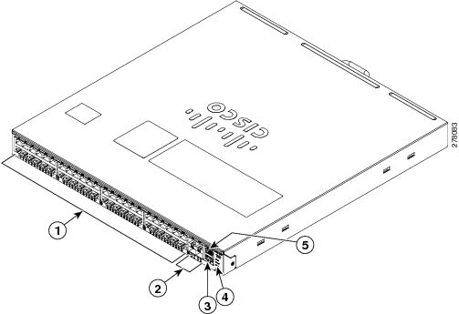
Figure 1-1 Catalyst 4948E and Catalyst 4948E-F Switches—Front View of Chassis (Catalyst 4948E Switch Shown)
|
|
48 downlink ports |
|
Status LEDs |
|
|
4 uplink ports |
|
Console port |
|
|
Management port |
Note ![]() The orientation of the Cisco logo shown in Figure 1-1 identifies the chassis as a Catalyst 4948E switch. The Cisco logo that appears on the Catalyst 4948E-F chassis top cover is rotated 180 degrees. Additional labels are placed on the Catalyst 4948E-F top cover to denote the direction of the airflow through the chassis.
The orientation of the Cisco logo shown in Figure 1-1 identifies the chassis as a Catalyst 4948E switch. The Cisco logo that appears on the Catalyst 4948E-F chassis top cover is rotated 180 degrees. Additional labels are placed on the Catalyst 4948E-F top cover to denote the direction of the airflow through the chassis.
Figure 1-2 Catalyst 4948E and Catalyst 4948E-F Switches—Rear View of Chassis

|
|
Power supply 1 (primary) |
|
Power supply 2 (redundant) |
|
|
Fan tray |
This chapter describes the Catalyst 4948E and Catalyst 4948E-F switches and includes these sections:
•![]() Physical and Environmental Specifications
Physical and Environmental Specifications
Features
Table 1-1 lists the features of the Catalyst 4948E and the Catalyst 4948E-F switch chassis.
|
|
|
|---|---|
Chassis |
1-RU, 48 10/100/1000 ports plus 4 1-GB/10-GB ports, fixed configuration switch with redundant power supplies |
Uplink ports |
The chassis has 4 1-GB or 10-GB uplink ports. An SFP or SFP+ transceiver must be installed in the chassis port socket for the port to operate. Cable type and recommended cabling distance for each port is determined by the type of SFP or SFP+ transceiver installed in the uplink port. A bicolor port link status LED is associated with each uplink port. LED colors indicate the following status: • • • • See "Transceiver, Chassis Connectors, and Cable and Adapter Specifications" for supported SFP and SFP+ transceiver descriptions, specifications, and cabling distances. |
Downlink ports |
• • • • • |
Console port |
A console serial port (RJ-45) is provided for switch management using standard console equipment. Additional information including a connector pinout table is provided in "Transceiver, Chassis Connectors, and Cable and Adapter Specifications"for the console port. Note |
Ethernet management port |
• • |
RESET switch |
• • |
Fan tray Catalyst 4948E chassis |
• Note • • • • • • – – |
Catalyst 4948E-F chassis |
• Note • • • • • • – – |
Power supplies Catalyst 4948E |
• – – Note • Note Note Note |
Catalyst 4948E-F |
• – • Note Note Note |
Physical and Environmental Specifications
Table 1-2 and Table 1-3 lists the Catalyst 4948E and Catalyst 4948E-F switch chassis environmental and physical specifications.
|
|
|
|---|---|
Environmental |
|
Temperature, operating |
Certified for operation: 32° to 104°F (0° to 40°C) Designed and tested for operation: 32° to 131°F (0° to 55°C) |
Temperature, nonoperating and storage |
Chassis unpackaged: -4° to 149°F (-20° to 65°C) Chassis in protective shipping package: -40° to 158°F (-40° to 70°C) |
Thermal transition |
0.5°C per minute (hot to cold) 0.33°C per minute (cold to hot) |
Humidity (RH), ambient (noncondensing) operating |
Operating: 5% to 90% Nonoperating and storage: 5% to 95% |
Altitude, operating |
Certified for operation: 0 to 6500 ft (0 to 2000 m) Designed and tested for operation: -200 to 10,000 ft (-60 to 3000 m) |
Heat Dissipation |
1364 BTU/hour (worst case) |
Shock and Vibration |
Refer to "Regulatory Compliance and Safety Information" for shock and vibration compliance information for the switch. |
Physical Characteristics |
|
Dimensions (H x W x D) |
• • • |
Weight |
• • |
Airflow |
• • |
Fan Tray
Both the Catalyst 4948E and the Catalyst 4948E-F switch chassis have a fan tray that is mounted in the rear of the chassis between the two power supplies. The Catalyst 4948E chassis fan tray (WS-X4993=) provides front-to-back air flow in the chassis and has a front panel that is color-coded dark grey. The Catalyst 4948E-F chassis fan tray (WS-X4993-F=) provides back-to-front air flow and has a front panel that is color-coded blue.
Note ![]() The two fan trays are not interchangeable between the Catalyst 4948E and the Catalyst 4948E-F chassis. The WS-X4993-F fan tray is keyed to prevent insertion in the Catalyst 4948E chassis.
The two fan trays are not interchangeable between the Catalyst 4948E and the Catalyst 4948E-F chassis. The WS-X4993-F fan tray is keyed to prevent insertion in the Catalyst 4948E chassis.
Individual fan speed within the fan trays is controlled by redundant temperature sensors located at the air flow inlet (in the front of the chassis for the Catalyst 4948E and in the rear of the chassis for the Catalyst 4948E-F). There are six programmable temperature thresholds that trigger fan speed change. If there is an individual fan failure, the fan speed on the remaining fans is adjusted to try to compensate for the loss of the fan.
Table 1-4 lists the fan speed settings and the associated temperature thresholds.
|
|
|
|
|---|---|---|
Speed 0 |
41% |
T2—89.6°F (32°C) Note |
Speed 1 |
56% |
• • Note |
Speed 2 |
75% |
T3—95.0°F (35°C) T6—116.6°F (47°C) Note |
Speed 32 |
100% |
T5—Greater than 109.4°F (43°C) |
1 Pulse-Width Modulation 2 Speed 3 is a fixed value and cannot be altered. |
Catalyst 4948E Fan Tray (WS-X4993=)
The Catalyst 4948E fan tray (WS-X4993) contains four variable-speed, 12 VDC fans. (See Figure 1-3.) The fan tray is mounted in the rear of the chassis between the two power supplies.
Note ![]() The WS-X4993 fan tray is not interchangeable with the WS-X4993-F fan tray.
The WS-X4993 fan tray is not interchangeable with the WS-X4993-F fan tray.
Figure 1-3 Catalyst 4948E Fan Tray

|
|
Backplane connector |
|
12 VDC fan (4X). Air is drawn in from the front of the chassis and exhausted through the rear of the chassis. |
|
|
Captive installation screw (2X) |
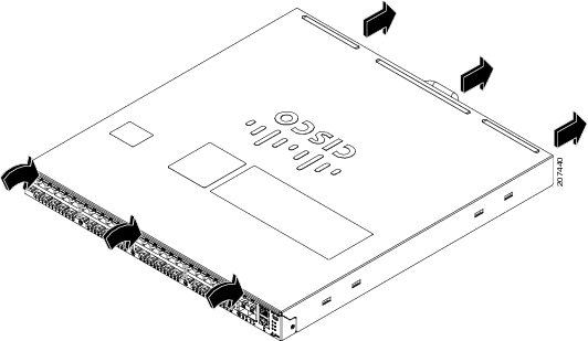
The fan tray draws in air through vents at the front of the chassis and exhausts it through the rear of the chassis as shown in Figure 1-4.
Figure 1-4 Catalyst 4948E Chassis Airflow
Catalyst 4948E-F Fan Tray (WS-X4993-F=)
The Catalyst 4948E-F chassis fan tray (WS-X4993-F=) contains four variable-speed, 12 VDC fans. (See Figure 1-5.) The fan tray is mounted in the rear of the chassis between the two power supplies.
Note ![]() The WS-X4993-F fan tray is keyed to prevent insertion into the Catalyst 4948E switch chassis.
The WS-X4993-F fan tray is keyed to prevent insertion into the Catalyst 4948E switch chassis.
Figure 1-5 Catalyst 4948E-F Fan Tray
|
|
Backplane connector |
|
12 VDC fan (4X). Air is drawn in from the rear of the chassis and exhausted through the front of the chassis. |
|
|
Captive installation screw (2X) |
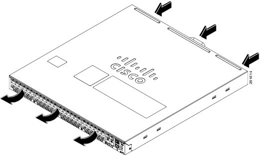
The fan tray draws in air through vents at the rear of the chassis and exhausts it through the front of the chassis as shown in Figure 1-6.
Figure 1-6 Catalyst 4948E-F Chassis Airflow
Front Panel LEDs
A set of LEDs on the chassis front panel provide visual status for the switch. (See Figure 1-7.) Table 1-5 lists the Catalyst 4948E and Catalyst 4948E-F switch chassis front panel LEDs and their meanings.
Figure 1-7 Front Panel LEDs

|
|
PS1 (power supply 1) |
|
STATUS |
|
|
PS2 (power supply 2) |
|
MGT (management port LED) |
|
|
FAN (fan tray) |
|
LINK (port status). One LED for each uplink and downlink port. |
|
|
|
|---|---|
STATUS |
Green—The system is up and running. Red—System fault. Flashing amber—Power-on self-test (POST) boot up. Off—System is not powered up. |
LINK 48 10/100/1000 downlink port LEDs and 4 SFP/SFP+ uplink port LEDs |
Green—Link is established. Amber—Administrative disabled. Off—No link is detected. |
FAN |
Green—Fan tray OK. Red—One or more fan failures. |
PS1 |
Green—AC-input or DC-input power is OK. Red—Power supply fault detected. |
PS2 |
Green—AC-input or DC-input power is OK. Red—Power supply fault detected. |
1 There are three additional LEDs mounted on the power supply front panel that provide power supply status. These LEDs are only visible from the back of the chassis. For a description of the LEDs, see the "300 W AC-Input Power Supply (PWR-C49E-300AC-R)" section. |
 Feedback